US7875029B1 - Surgical device switchable between clip application and coagulation modes - Google Patents
Surgical device switchable between clip application and coagulation modesDownload PDFInfo
- Publication number
- US7875029B1 US7875029B1US12/435,368US43536809AUS7875029B1US 7875029 B1US7875029 B1US 7875029B1US 43536809 AUS43536809 AUS 43536809AUS 7875029 B1US7875029 B1US 7875029B1
- Authority
- US
- United States
- Prior art keywords
- surgical apparatus
- effector
- clip
- coagulation
- incorporating
- Prior art date
- Legal status (The legal status is an assumption and is not a legal conclusion. Google has not performed a legal analysis and makes no representation as to the accuracy of the status listed.)
- Expired - Fee Related, expires
Links
Images


Classifications
- A—HUMAN NECESSITIES
- A61—MEDICAL OR VETERINARY SCIENCE; HYGIENE
- A61B—DIAGNOSIS; SURGERY; IDENTIFICATION
- A61B18/00—Surgical instruments, devices or methods for transferring non-mechanical forms of energy to or from the body
- A61B18/04—Surgical instruments, devices or methods for transferring non-mechanical forms of energy to or from the body by heating
- A61B18/12—Surgical instruments, devices or methods for transferring non-mechanical forms of energy to or from the body by heating by passing a current through the tissue to be heated, e.g. high-frequency current
- A61B18/14—Probes or electrodes therefor
- A61B18/1442—Probes having pivoting end effectors, e.g. forceps
- A61B18/1445—Probes having pivoting end effectors, e.g. forceps at the distal end of a shaft, e.g. forceps or scissors at the end of a rigid rod
- A61B18/1447—Probes having pivoting end effectors, e.g. forceps at the distal end of a shaft, e.g. forceps or scissors at the end of a rigid rod wherein sliding surfaces cause opening/closing of the end effectors
- A—HUMAN NECESSITIES
- A61—MEDICAL OR VETERINARY SCIENCE; HYGIENE
- A61B—DIAGNOSIS; SURGERY; IDENTIFICATION
- A61B17/00—Surgical instruments, devices or methods
- A61B17/12—Surgical instruments, devices or methods for ligaturing or otherwise compressing tubular parts of the body, e.g. blood vessels or umbilical cord
- A61B17/128—Surgical instruments, devices or methods for ligaturing or otherwise compressing tubular parts of the body, e.g. blood vessels or umbilical cord for applying or removing clamps or clips
- A61B17/1285—Surgical instruments, devices or methods for ligaturing or otherwise compressing tubular parts of the body, e.g. blood vessels or umbilical cord for applying or removing clamps or clips for minimally invasive surgery
- A—HUMAN NECESSITIES
- A61—MEDICAL OR VETERINARY SCIENCE; HYGIENE
- A61B—DIAGNOSIS; SURGERY; IDENTIFICATION
- A61B17/00—Surgical instruments, devices or methods
- A61B17/10—Surgical instruments, devices or methods for applying or removing wound clamps, e.g. containing only one clamp or staple; Wound clamp magazines
- A61B17/105—Wound clamp magazines
- A—HUMAN NECESSITIES
- A61—MEDICAL OR VETERINARY SCIENCE; HYGIENE
- A61B—DIAGNOSIS; SURGERY; IDENTIFICATION
- A61B18/00—Surgical instruments, devices or methods for transferring non-mechanical forms of energy to or from the body
- A61B18/04—Surgical instruments, devices or methods for transferring non-mechanical forms of energy to or from the body by heating
- A61B18/12—Surgical instruments, devices or methods for transferring non-mechanical forms of energy to or from the body by heating by passing a current through the tissue to be heated, e.g. high-frequency current
- A61B18/14—Probes or electrodes therefor
- A61B18/1402—Probes for open surgery
- A—HUMAN NECESSITIES
- A61—MEDICAL OR VETERINARY SCIENCE; HYGIENE
- A61B—DIAGNOSIS; SURGERY; IDENTIFICATION
- A61B18/00—Surgical instruments, devices or methods for transferring non-mechanical forms of energy to or from the body
- A61B2018/00571—Surgical instruments, devices or methods for transferring non-mechanical forms of energy to or from the body for achieving a particular surgical effect
- A61B2018/00589—Coagulation
Definitions
- the present inventionrelates generally to a surgical clip applier and a method for surgical clip application.
- Surgical clip appliershave been utilized to overcome some of the difficulties associated with suturing.
- a large subset of clip appliers known in the artare single-use devices, capable of deploying only a single clip or set of clips at one time.
- a new devicemust be utilized, or the device must be reloaded with another cartridge of clips.
- multiple clipsmust be placed at different locations in the body, such use of multiple tools is time consuming, expensive and wasteful.
- Some surgical clip appliers known in the artare capable of deploying multiple clips, one after the other, in different locations in the body. However, such tools are complex and bulky, and may be incapable of deploying clips properly sized to be useful in some minimally invasive surgical procedures.
- Coagulation-based devices for dissecting tissuealso are known and used in surgical procedures. These devices clamp tissue, deliver energy such as RF energy or ultrasound to tissue in order to cause coagulation to heat seal the tissue, then use a knife to cut the tissue.
- a surgeonmay use such a device, for example, to separate side branches from a saphenous vein during endoscopic vein harvesting in preparation for coronary artery bypass graft (CABG) surgery.
- CABGcoronary artery bypass graft
- the surgeonmay encounter blood vessels that are larger than a coagulation-based device can safely handle. Consequently, the surgeon must then set aside the coagulation device and switch to a separate clip applier.
- FIG. 1is a perspective view of an exemplary surgical clip applier.
- FIG. 2is a cutaway perspective view of the distal end of an exemplary effector of the surgical clip applier of FIG. 1 .
- FIG. 2Ais a side cutaway view of the exemplary effector of the surgical clip applier of FIG. 1 .
- FIG. 3is a perspective view of a portion of the distal end of the exemplary effector of the surgical stapler of FIG. 1 , with a clip in ready position.
- FIG. 4is a top view of the distal end of the exemplary effector of the surgical stapler of FIG. 1 , with the jaws open.
- FIG. 5is a perspective view of a portion of the distal end of the exemplary effector of the surgical stapler of FIG. 1 , with a closed clip between the jaws.
- FIG. 6is a top view of a portion of the distal end of the exemplary effector of the surgical stapler of FIG. 1 , with a closed clip between the jaws.
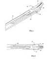
- FIG. 7is a perspective view of the exemplary effector of the surgical clip applier of FIG. 1 .
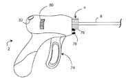
- FIG. 8is a side view of a handle of an exemplary hybrid clip applier.
- FIG. 9is a detail perspective view of the end of one of the jaws of the exemplary hybrid clip applier of FIG. 8 .
- a surgical clip applier 2includes a handle 4 connected to an effector 6 .
- the clip applier 2may be substantially as described in U.S. patent application Ser. No. 12/370,576, filed on Feb. 12, 2009, which is hereby incorporated by reference in its entirety.
- the handle 4may be connected directly to the effector 6 , or may be connected to a shaft 8 that in turn is connected to the effector 6 .
- the shaft 8may be rigid, articulated or flexible.
- the handle 4may have any suitable configuration, as described in greater detail below.
- the effector 6may be sized to pass through an access port in a patient for use in a minimally-invasive surgical procedure.
- the effector 6may be sized and shaped to allow it to be inserted through an access port in a patient of 5 mm in diameter or less. Alternately, the effector 6 may be sized and/or shaped differently.
- the effector 6may be substantially rigid, substantially flexible, or a combination of both.
- the handle 4may include one or more triggers, levers, knobs, buttons or other input features used to actuate and/or control the effector 6 .
- the effector 6may hold one or more clips 10 within a passage 12 in a housing 14 .
- the housing 14may be elongated longitudinally, and may have a longitudinal centerline.
- the passage 12 in the housing 14may itself have a longitudinal centerline that is offset from and generally parallel to the longitudinal centerline of the housing 14 .
- the passage 12may be located in and/or oriented within the housing 14 in any other suitable manner.
- the passage 12may have a lower surface 16 and an upper surface 18 .
- One or more clips 10are located within the passage 12 .
- the clips 10may be oriented at an angle to the longitudinal centerline of the passage 12 and/or the longitudinal centerline of the housing 14 .
- the clips 10may be constrained within the passage 12 by the surfaces 16 , 18 , as well as the lateral surfaces of the passage 12 .
- the clips 10may be independent from one another, and placed adjacent to one another. Alternately, the clips 10 may be connected to or associated with one another in any suitable manner.
- the clips 10may be coated with parylene such that they are held together as a single assembly, in order to facilitate manufacture of the clip applier 2 .
- one or more clips 10may be frangibly connected to a wire or backbone (not shown) from which each clip 10 may be sheared upon deployment, in order to facilitate manufacture of the clip applier 2 .
- a clip pusher 20may be located in the passage 12 , proximal to the clip or clips 10 .
- the clip pusher 20may contact the most proximal clip 10 in the passage 12 , and exert a force on that most proximal clip 10 in the distal direction.
- the distal forcemay be transmitted from each clip 10 to the clip 10 distally next in line, such that the clip pusher 20 exerts a distal force on all of the clips 10 .
- the clip pusher 20may be biased distally, or may be selectively urged distally.
- such biasmay be provided by a compression spring 22 , by a pneumatic force, by a magnetic or electromagnetic actuator, a solenoid, or any other suitable structure or mechanism.
- the distal end of the compression spring 22may abut or may be fastened to the clip pusher 20 , and the proximal end of the compression spring 22 may abut or be fixed to a wall 24 or other portion of the housing 14 such that the proximal end of the compression spring 22 is held in a substantially fixed location.
- the compression spring 22may be arranged differently relative to the housing 14 , if desired.
- the handle 4may be used to control the timing of the application of distal force to the clip pusher 20 , which may be applied by a compression spring 22 , by a pneumatic force, by a magnetic or electromagnetic actuator, a solenoid, or any other suitable structure or mechanism.
- a lower ramp 26may be located at the distal end of the passage 12 .
- the lower ramp 26advantageously is oriented at the same angle to the longitudinal centerline of the housing 16 as the clip or clips 10 .
- the distalmost clip 10 in the passagemay be pressed against the ramp 26 by the compressive force applied to that clip 10 by the clip pusher 20 .
- a upper ramp 28may be generally parallel to the lower ramp 26 , and spaced apart from the lower ramp 26 by a distance slightly greater than the thickness of the clip or clips 10 . Friction between the distalmost clip 10 and the ramps 26 , 28 holds the distalmost clip 10 in place.
- a detent or other mechanismmay be used to hold the distalmost clip in place.
- An opening 30is located between the distal ends of the ramps 26 , 28 . Clips 10 are sequentially urged through that opening 30 , as described in greater detail below.
- a pusher 32is slidable along a pusher slot 34 in the housing 14 .
- the pusher 32may be generally elongated, and may have a generally rectangular cross-section. Alternately, the pusher 32 may be shaped differently.
- the pusher slot 34may be generally parallel to and underneath the passage 12 . Alternately, the pusher slot 34 may be located and/or oriented differently.
- the distal end of the pusher slot 34includes an aperture 36 connecting the pusher slot 34 to the passage 12 .
- the aperture 36is preferably oriented such that the distal end of the pusher 32 extends out of the aperture 36 onto the lower ramp 26 . Alternately, the pusher slot 34 is omitted, and the pusher 32 is slidable along a trench or other feature in the housing 14 .
- the effector 6includes an actively-controlled crimper 40 .
- the crimper 40includes a first jaw 42 , a second jaw 44 , and a control arm 46 .
- Each jaw 42 , 44may be substantially planar, and the jaws 42 , 44 may be positioned such that the second jaw 44 rests on the upper surface of the first jaw 42 .
- at least one jaw 42 , 44may be shaped or oriented differently.
- the proximal end of each jaw 42 , 44may be configured to pivot about a post 48 within the housing 14 , where the post 48 has a substantially fixed location within the housing 14 .
- each jaw 42 , 44may include a generally circular opening 50 that receives the post 48 therein.
- an angled control slot 52is defined in each jaw 42 , 44 .
- the control slot 52 of each jaw 42 , 44is oriented such that the distal end of the control slot 52 is located laterally outward from the proximal end of the control slot 52 .
- the control slot 52 of the first jaw 42may be oriented laterally in the opposite direction as the control slot 52 of the second jaw 44 .
- each jaw 42 , 44ends in a finger 60 , where the fingers 60 are configured to receive a clip 10 therebetween.
- Each finger 60may be angled relative to the longitudinal centerline of the effector 6 approximately the same amount as the lower ramp 26 , and may extend outward from the opening 30 such that a clip 10 can slide smoothly along the lower ramp 26 , out of the opening 30 , and into the space between the fingers 60 .
- the inner surface of each finger 60may include a trench 62 defined therein.
- Each trench 62may be sized to be substantially as wide as a clip 10 .
- Each trench 62may be deep enough such that the distal end 64 of each trench 62 acts as a stop, such that a clip 10 is advanced between the fingers 60 until the distal end of the clip 10 encounters the ends 64 of the trenches 62 in the fingers 60 .
- the arm 46may extend generally parallel to the jaws 42 along at least part of its length.
- the distal tip 66 of the arm 46is bent downward or otherwise configured to enter both control slots 52 of the jaws 42 , 44 .
- the distal tip 66 of the arm 46is located at the proximal end of each slot 52 , and the fingers 60 of the jaws 42 , 44 are spaced apart from one another.
- a feature 66is located on the control arm 46 other than at its distal end, and extends downward into both control slots 52 of the jaws 42 , 44 .
- the clips 10may be generally U-shaped, or otherwise configured. Each clip 10 may lie substantially in a single plane. That is, each clip 10 is shaped such that a single plane extends through and substantially bisects the entire clip 10 . Alternately, at least one clip 10 does not lie substantially in a single plane.
- the longitudinal and lateral dimensions of the clips 10 overallmay both be substantially larger than the height of the clips 10 . Alternately, the clips 10 may be sized differently.
- the clips 10may be plastically deformable. That is, the clips 10 may undergo a permanent deformation when subjected to a stress exceeding its yield value. In other words, plastic deformation is deformation that remains after the load that caused it is removed, or that would remain if the load were removed.
- the clips 10may be fabricated from stainless steel, titanium or any other suitable plastically-deformable material. Alternately, the clips 10 may be elastically deformable. If so, the clips 10 may be fabricated from nickel-titanium alloy or any other suitable elastic or superelastic material. Each clip 10 may be fabricated from a single wire or other piece of material, having a rectangular, circular or other cross-section. However, the clips 10 may be fabricated in any suitable manner.
- the cross-section of each clip 10may be substantially constant along the entire clip 10 , or may vary at different locations along the clip 10 . For example, the cross-sectional area of the clip 10 at certain locations may be less than at other locations, in order to promote bending in those locations having a lesser cross-sectional area.
- the cross-sectional shape of the clip 10may be square, rectangular, circular, oval or any other suitable shape, and may be substantially constant along the entire clip 10 or vary at different locations along the clip 10 .
- the handle 4may include any mechanism, mechanisms, structure or structures configured to actuate the effector 6 .
- the proximal end of the pusher 32 and the proximal end of the control arm 46may extend proximally out of the effector 6 .
- the handle 4may be configured in any suitable manner to control the motion of the pusher 32 and control arm 46 .
- the pusher 32 and/or control arm 46 , or structures or mechanisms connected to themmay extend through the shaft 8 to the handle 4 .
- the handle 4may include any suitable mechanism or mechanisms that provide for control of the pusher 32 and control arm 46 , and may include a source of stored energy for actuating the effector 6 .
- the source of stored energymay be mechanical (such as a spring), electrical (such as a battery), pneumatic (such as a cylinder of pressurized gas) or any other suitable source of stored energy.
- the source of stored energy, its regulation, and its use in actuating an effector 6may be as described in U.S. patent application Ser. No. 10/392,336, filed on Mar. 19, 2003, or U.S. patent application Ser. No. 11/054,265, filed on Feb. 9, 2005, which are herein incorporated by reference in their entirety.
- the handle 4may instead, or also, include a connector or connectors suitable for receiving stored energy from an external source, such as a hose connected to a hospital utility source of pressurized gas or of vacuum, or an electrical cord connectable to a power source.
- the handle 4may be omitted, and the effector 6 may be actuated directly by a surgical robot such as the DaVinci® surgical robot of Intuitive Surgical, Inc. of Sunnyvale, Calif.
- the shaft 8may be utilized, if desired, or the effector 6 may be mounted directly on an arm of the surgical robot.
- the surgical robotmay provide all energy needed to actuate the effector 6 , and may directly control the actuation of the effector 6 .
- the effector 6may include a cutaway, trough, lumen, ring or other feature (not shown) to allow the effector 6 to follow a guidewire to a treatment site.
- FIGS. 8-9another embodiment of the clip applier 2 is configured to utilize one or more fingers 60 to coagulate tissue, as well as to close clips 10 .
- the clip applier 2is configured to either coagulate tissue in a coagulation mode or to deploy clips in a clip application mode.
- the two modesare mutually exclusive, to prevent electrical or other energy from traveling through a clip 10 that is being deployed or that has been deployed, which may result in injury to the patient and/or damage to the clip applier 2 .
- at least one coagulation surface 70may be located on an inner surface of at least one finger 60 , facing the other finger 60 .
- At least one coagulation surface 70may be located on an inner surface of at least one finger 60 , above and/or below the trench 62 defined in that finger 60 .
- at least one coagulation surface 70may be located on an inner surface of at least one finger 60 , distal to the trench 62 defined in that finger 60 .
- Each coagulation surface 70may be oriented generally longitudinally along the corresponding finger 60 .
- the entire inner surface 16 of the finger 60may be a coagulation surface 70 .
- Each coagulation surface 70is connected to an energy source in the handle 4 in any appropriate manner.
- one or more wires 72 or waveguidesmay extend from a coagulation surface 70 through the shaft 8 to the energy source in the handle 4 .
- the energy source connected to each coagulation surface 70may be different from the energy source used to deploy clips 10 , where such an energy source is utilized to deploy clips 10 .
- the handle 4may include a cylinder of pressurized gas, a spring, or other source of stored energy used to deploy clips 10 , and a connection to an electric power source for actuating the coagulation surfaces 70 .
- the energy source connected to each coagulation surface 70instead may be the same as the energy source used to deploy clips 10 .
- the energy sourceis not in the handle 4 , but rather is external to the clip applier 2 , such that energy passes from outside the clip applier 2 through the handle 4 to the coagulation surfaces 70 via a wire, wires, waveguide or waveguides 72 , or such that energy passes from a source outside the clip applier 2 directly to the coagulation surfaces 70 via a wire, wires, waveguide or waveguides 72 .
- Each coagulation surface 70may be configured in any suitable manner to deliver RF energy, ultrasound, heat, electricity or any other kind of energy to tissue.
- at least one coagulation surface 70may be a complete mechanism or other device configured to convert electrical or other energy into a different kind of energy suitable for causing coagulation.
- Such mechanisms and devicesare known in the art.
- Each coagulation surface 70may be a pole of a bipolar coagulator, or each may be unipolar. Bipolar cutting and coagulation is known in the art, and is described in, for example, U.S. Pat. No. 5,281,216 to Klicek, which is hereby incorporated by reference in its entirety.
- the coagulation surface or surfaces 70 on one finger 60form one pole, and the coagulation surface or surfaces 70 on the other finger 60 form the other pole.
- the coagulation surface or surfaces 70 on the other finger 60form the other pole.
- at least one of those coagulation surfaces 70has a different pole than at least one other coagulation surface 70 on that finger 60 .
- the clip applier 2may be configured to deploy clips 10 or to apply energy to the coagulation surfaces 70 , based on the selection of the user.
- the handle 4may include a trigger 74 used for deploying clips 10 and a switch 76 for actuating the coagulating surfaces 70 .
- the switch 76may be located elsewhere than the handle 4 , and be connected to the clip applier 2 in any suitable manner.
- the switch 76may be a foot pedal connected electrically to the coagulation surfaces 70 , whether via the handle 4 or directly to the coagulation surfaces 70 via the wires or waveguides 72 .
- Such a switch 76may be mechanical, electrical, a combination thereof, or a different kind of switch.
- motion of the switch 76may physically lock out the clips 10 from firing, such as by moving a tab into engagement with the trigger 74 to prevent actuation of the trigger 74 .
- a separate lock 78may be provided on the handle 4 , where that lock 78 is actuated (optionally or as an affirmative requirement) to lock out the clips 10 from firing prior to application of energy to the actuation surfaces.
- the switch 76is used to toggle between clip application mode and coagulation mode, and the trigger 74 is then used to actuate the clip applier 2 in each mode.
- a master switch 82is provided for toggling between clip application mode and coagulation mode, after which the trigger 74 is used to deploy clips 10 or the switch 76 is used to deliver energy to the coagulation surfaces 70 .
- the handle 8may include any other features that allow the user to selectively deploy staples and coagulate tissue.
- the clip applicator 2may be configured to deploy clips 10 and apply energy to the coagulation surfaces 70 at the same time, either at the selection of the user, or as the only mode of operation of the clip applier 2 .
- the clip applier 2may automatically toggle between clip application mode and coagulation mode based on feedback from compression of the tissue between the fingers 60 , such that the user does not select the mode of operation of the clip applier 2 .
- the handle 4may include a dial 80 for rotating the shaft 8 relative to the handle 4 .
- the shaft 8may extend into the handle 4 , and the dial 80 may be directly fixed to the shaft 8 , such that rotation of the dial 80 causes rotation of the shaft 8 .
- the dial 80may extend through an opening in the surface of the handle 4 .
- at least one gearis interposed between the dial 80 and the shaft 8 . In this way, the user can rotate the shaft 8 and thus the end effector 6 relative to the handle 4 , such that the user need not rotate the entire clip applier 2 to properly orient the effector 6 relative to tissue to be treated.
- each jaw 42 , 44may be conductive and may be a different pole of a bipolar coagulating system. Consequently, the fingers 60 at the ends of the jaws 42 , 44 are different poles of a bipolar coagulating system.
- Energymay be transmitted to the jaws 42 , 44 in substantially the same manner described above in which energy is transmitted to discrete coagulation surfaces 70 , such as through wires or waveguides 72 .
- an insulator or dielectricmay be interposed between them within the effector 6 , in order to prevent unintended energy flow between the jaws 42 , 44 .
- the post 48 and the arm 46are advantageously nonconductive for the same reason.
- the jaws 42 , 44may be actuated to coagulate tissue in substantially the same manner described above in which the coagulation surfaces 70 are actuated.
- the operation of the clip applier 2is described with regard to a generic surgical procedure.
- the clip applier 2may be used in the course of any suitable surgical procedure, whether that surgical procedure is minimally-invasive or open, and whether the clip applier 2 is configured for manual or robotic actuation.
- the surgical stapler 2may be used to staple wounds or incisions in the skin together, for cardiac surgery, for hernia repair, for abdominal wall closure, for anti-reflux or other bariatric procedures, for intestinal repair, for dura mater surgery or other brain surgery, for aneurysm closure, for anastomosis, or for any other suitable medical use.
- the distal end of the effector 6may be placed in proximity to the tissue to be clipped.
- the fingers 60may be placed around a blood vessel.
- the effector 6is in an initial state. In the initial state, the fingers 60 are spaced apart from one another in an open configuration, prepared to receive a clip 10 .
- the userthen actuates the handle 4 and/or other component of the clip applier 2 to begin the deployment sequence.
- the handle 4 or other mechanismcontrols the motion of the components of the effector 6 in any suitable manner.
- the pusher 32is advanced distally.
- the pusher 32As the pusher 32 advances, it contacts the proximal surface of the distalmost clip 10 , then pushes that clip along the lower ramp 26 and through the opening 30 . As the clip 10 moves through the opening 30 , the lateral surfaces of the clip 10 enter the trenches 62 of the fingers 60 , such that the fingers 60 can effectively hold the clip 10 therebetween. Motion of the clip 10 ceases when the pusher 32 ceases its distal motion, or when the distal end of the clip 10 encounters the distal end 64 of at least one trench 62 . The clip 10 is thereby in position for placement on tissue. This position of the clip 10 may be referred to as the “ready position.” The clip 10 may be placed around a blood vessel, onto tissue, or in any other suitable position before or after the clip 10 has reached the ready position.
- the control arm 46is then actuated to move distally; advantageously, the control arm 46 also moves substantially linearly.
- the distal tip 66 of the control arm 46moves distally as well.
- the distal tip 66is located within the control slots 52 of the jaws 42 , 44 .
- the distal tip 66moves distally, the fingers 60 move closer together, closing the clip 10 .
- the distal tip 66may travel all the way to the distal end of at least one control slot 52 , or may be controlled by the handle 4 to move a shorter distance along at least one control slot 52 .
- the distal tip 66moves distally until the clip 10 is completely closed. After that deployment, the distal tip 66 is moved proximally, causing the fingers 60 to move apart and release the clip 10 .
- the control arm 46is moved proximally until the jaws 42 , 44 return to their initial, open position in which the fingers 60 can receive another clip 10 between them.
- the jaws 42 , 44may be actively controlled at all times.
- Active controlmeans that the opening and closing of the jaws 42 is controlled solely by the control arm 46 , and is not dependent on or responsive to other input, such as contact between one or more of the fingers 60 and tissue. Alternately, the jaws 42 , 44 may be otherwise controlled.
- the pusher 32is also moved proximally to its initial position. This motion may occur at any time after the clip 10 has been pushed into its ready position between the fingers 60 .
- the pusher 32may move proximally before, during or after the distal tip 66 of the control arm 46 moves distally to close the clip 10 between the fingers 60 .
- the clip pusher 20may apply a compressive force collectively to all of the clips 10 in the passage before, during and after each distalmost clip 10 is urged into the ready position. As a result, as the pusher 32 moves proximally, the distalmost remaining clip 10 in the passage 12 is urged distally against the pusher 32 .
- the clips 10may be advanced without the need for a belt, carrier or other mechanism to engage them each individually and separately and move them distally.
- the pusher 32may then cease its proximal motion.
- the distal end of the pusher 32may be located in the passage 12 , or may be located in the pusher slot 34 .
- the effector 6is ready for another actuation at any other suitable location in the patient.
- the clip applier 2 with both clip application and coagulation modesis actuated substantially as described above with regard to clip application.
- the dial 80may be rotated to orient the shaft 8 and thus the effector 6 in the desired position.
- the trigger 74is simply squeezed.
- the master switch 82is actuated to select clip application mode prior to squeezing the trigger 74 .
- any other suitable control or controlsmay be used to deploy one or more clips 10 . If the clip applier 2 is set to coagulation mode, then the trigger 74 may be locked out as described above until clip application mode is selected.
- the clip applicator 2is placed in coagulation mode. This may be done in any suitable manner, as set forth above.
- the switch 76is simply depressed, and energy is applied to the coagulation surfaces 70 .
- the fingers 60may be moved toward one another to compress tissue therebetween as a consequence of actuating the switch 76 .
- the fingers 60may be moved together by a partial squeeze of the trigger 74 sufficient to close the jaws 42 , 44 toward one another, where motion of a clip 10 between the jaws 42 , 44 is locked out in any suitable manner.
- the energyis transmitted to the coagulation surfaces 70 via the wires or waveguides 72 , causing the tissue between the fingers that is in contact with the coagulation surfaces 70 to coagulate and seal.
- the energy transmitted to the coagulation surfaces 70may also cut through the tissue between the fingers 60 , such that application of energy to the coagulation surfaces 70 both seals and cuts tissue.
- the effector 6is then moved away from the tissue.
- the usercan then reposition the effector 6 at a different location in the patient to treat different tissue, whether than location is immediately adjacent to the previous location, or at a different location in the body altogether.
- the clip applier 2can thus be used repeatedly in the patient to treat tissue at multiple surgical sites, both with clips and with coagulation. The user may continue in this manner until the clips are exhausted or until the treatment of tissue in the body is complete. In this way, the time and material needed to treat tissue within the patient may be reduced compared to conventional medical devices.
Landscapes
- Health & Medical Sciences (AREA)
- Surgery (AREA)
- Life Sciences & Earth Sciences (AREA)
- Engineering & Computer Science (AREA)
- Heart & Thoracic Surgery (AREA)
- Veterinary Medicine (AREA)
- Nuclear Medicine, Radiotherapy & Molecular Imaging (AREA)
- Biomedical Technology (AREA)
- Public Health (AREA)
- Medical Informatics (AREA)
- Molecular Biology (AREA)
- Animal Behavior & Ethology (AREA)
- General Health & Medical Sciences (AREA)
- Reproductive Health (AREA)
- Vascular Medicine (AREA)
- Physics & Mathematics (AREA)
- Plasma & Fusion (AREA)
- Otolaryngology (AREA)
- Surgical Instruments (AREA)
Abstract
Description
Claims (17)
Priority Applications (1)
| Application Number | Priority Date | Filing Date | Title |
|---|---|---|---|
| US12/435,368US7875029B1 (en) | 2009-05-04 | 2009-05-04 | Surgical device switchable between clip application and coagulation modes |
Applications Claiming Priority (1)
| Application Number | Priority Date | Filing Date | Title |
|---|---|---|---|
| US12/435,368US7875029B1 (en) | 2009-05-04 | 2009-05-04 | Surgical device switchable between clip application and coagulation modes |
Publications (1)
| Publication Number | Publication Date |
|---|---|
| US7875029B1true US7875029B1 (en) | 2011-01-25 |
Family
ID=43479734
Family Applications (1)
| Application Number | Title | Priority Date | Filing Date |
|---|---|---|---|
| US12/435,368Expired - Fee RelatedUS7875029B1 (en) | 2009-05-04 | 2009-05-04 | Surgical device switchable between clip application and coagulation modes |
Country Status (1)
| Country | Link |
|---|---|
| US (1) | US7875029B1 (en) |
Cited By (66)
| Publication number | Priority date | Publication date | Assignee | Title |
|---|---|---|---|---|
| US20100012700A1 (en)* | 2008-07-17 | 2010-01-21 | Stanley Fastening Systems, Lp | Fastener driving device with mode selector and trigger interlock |
| US8480703B2 (en) | 2010-11-19 | 2013-07-09 | Covidien Lp | Surgical device |
| US20130282021A1 (en)* | 2011-10-19 | 2013-10-24 | Ethicon Endo-Surgery, Inc. | Clip applier adapted for use with a surgical robot |
| CN103462654A (en)* | 2013-10-08 | 2013-12-25 | 王学建 | Retaining clip for reconstructing skull base |
| CN103479433A (en)* | 2013-10-07 | 2014-01-01 | 王学建 | Double-pinhole fixator for neurosurgery department |
| CN103479432A (en)* | 2013-10-06 | 2014-01-01 | 王学建 | Single-nail skull base reconstruction device |
| US20140039478A1 (en)* | 2012-08-01 | 2014-02-06 | Caymus Medical, Inc. | Systems and methods for percutaneous intravascular access for arteriovenous fistula |
| US8701960B1 (en) | 2009-06-22 | 2014-04-22 | Cardica, Inc. | Surgical stapler with reduced clamp gap for insertion |
| USD750245S1 (en)* | 2012-03-08 | 2016-02-23 | Covidien Lp | Handle for laparoscopic device with integral rotation wheel |
| US9433417B2 (en)* | 2009-05-26 | 2016-09-06 | Joimax Gmbh | Device and method for applying a medical lockable clip in a tissue area |
| EP3195822A1 (en)* | 2016-01-23 | 2017-07-26 | Covidien LP | Devices for tissue sealing and mechanical clipping |
| US10307202B2 (en) | 2015-12-03 | 2019-06-04 | Boston Scientific Scimed, Inc. | Electrocautery hemostasis clip |
| US10639032B2 (en) | 2017-06-30 | 2020-05-05 | Covidien Lp | Endoscopic surgical clip applier including counter assembly |
| US10653429B2 (en) | 2017-09-13 | 2020-05-19 | Covidien Lp | Endoscopic surgical clip applier |
| US10660723B2 (en) | 2017-06-30 | 2020-05-26 | Covidien Lp | Endoscopic reposable surgical clip applier |
| US10660651B2 (en) | 2016-10-31 | 2020-05-26 | Covidien Lp | Endoscopic reposable surgical clip applier |
| US10675043B2 (en) | 2017-05-04 | 2020-06-09 | Covidien Lp | Reposable multi-fire surgical clip applier |
| US10675112B2 (en) | 2017-08-07 | 2020-06-09 | Covidien Lp | Endoscopic surgical clip applier including counter assembly |
| US10702280B2 (en) | 2015-11-10 | 2020-07-07 | Covidien Lp | Endoscopic reposable surgical clip applier |
| US10702279B2 (en) | 2015-11-03 | 2020-07-07 | Covidien Lp | Endoscopic surgical clip applier |
| US10722236B2 (en) | 2017-12-12 | 2020-07-28 | Covidien Lp | Endoscopic reposable surgical clip applier |
| US10722235B2 (en) | 2017-05-11 | 2020-07-28 | Covidien Lp | Spring-release surgical clip |
| US10743887B2 (en) | 2017-12-13 | 2020-08-18 | Covidien Lp | Reposable multi-fire surgical clip applier |
| US10758245B2 (en) | 2017-09-13 | 2020-09-01 | Covidien Lp | Clip counting mechanism for surgical clip applier |
| US10765431B2 (en) | 2016-01-18 | 2020-09-08 | Covidien Lp | Endoscopic surgical clip applier |
| US10786263B2 (en) | 2017-08-15 | 2020-09-29 | Covidien Lp | Endoscopic reposable surgical clip applier |
| US10786273B2 (en) | 2018-07-13 | 2020-09-29 | Covidien Lp | Rotation knob assemblies for handle assemblies |
| US10786262B2 (en) | 2017-08-09 | 2020-09-29 | Covidien Lp | Endoscopic reposable surgical clip applier |
| US10806464B2 (en) | 2016-08-11 | 2020-10-20 | Covidien Lp | Endoscopic surgical clip applier and clip applying systems |
| US10806463B2 (en) | 2011-11-21 | 2020-10-20 | Covidien Lp | Surgical clip applier |
| US10828044B2 (en) | 2015-03-10 | 2020-11-10 | Covidien Lp | Endoscopic reposable surgical clip applier |
| US10828036B2 (en) | 2017-11-03 | 2020-11-10 | Covidien Lp | Endoscopic surgical clip applier and handle assemblies for use therewith |
| US10835341B2 (en) | 2017-09-12 | 2020-11-17 | Covidien Lp | Endoscopic surgical clip applier and handle assemblies for use therewith |
| US10835260B2 (en) | 2017-09-13 | 2020-11-17 | Covidien Lp | Endoscopic surgical clip applier and handle assemblies for use therewith |
| US10849630B2 (en) | 2017-12-13 | 2020-12-01 | Covidien Lp | Reposable multi-fire surgical clip applier |
| US10881445B2 (en) | 2017-02-09 | 2021-01-05 | Covidien Lp | Adapters, systems incorporating the same, and methods for providing an electrosurgical forceps with clip-applying functionality |
| US10905425B2 (en) | 2015-11-10 | 2021-02-02 | Covidien Lp | Endoscopic reposable surgical clip applier |
| US10932791B2 (en) | 2017-11-03 | 2021-03-02 | Covidien Lp | Reposable multi-fire surgical clip applier |
| US10932793B2 (en) | 2016-01-11 | 2021-03-02 | Covidien Lp | Endoscopic reposable surgical clip applier |
| US10932790B2 (en) | 2017-08-08 | 2021-03-02 | Covidien Lp | Geared actuation mechanism and surgical clip applier including the same |
| US10945734B2 (en) | 2017-11-03 | 2021-03-16 | Covidien Lp | Rotation knob assemblies and surgical instruments including the same |
| US10959737B2 (en) | 2017-12-13 | 2021-03-30 | Covidien Lp | Reposable multi-fire surgical clip applier |
| US10993721B2 (en) | 2018-04-25 | 2021-05-04 | Covidien Lp | Surgical clip applier |
| US11026696B2 (en) | 2012-05-31 | 2021-06-08 | Covidien Lp | Endoscopic clip applier |
| US11051828B2 (en) | 2018-08-13 | 2021-07-06 | Covidien Lp | Rotation knob assemblies and surgical instruments including same |
| US11051827B2 (en) | 2018-01-16 | 2021-07-06 | Covidien Lp | Endoscopic surgical instrument and handle assemblies for use therewith |
| US11058432B2 (en) | 2015-01-15 | 2021-07-13 | Covidien Lp | Endoscopic reposable surgical clip applier |
| US11071553B2 (en) | 2016-08-25 | 2021-07-27 | Covidien Lp | Endoscopic surgical clip applier and clip applying systems |
| US11116513B2 (en) | 2017-11-03 | 2021-09-14 | Covidien Lp | Modular surgical clip cartridge |
| US11116514B2 (en) | 2017-02-06 | 2021-09-14 | Covidien Lp | Surgical clip applier with user feedback feature |
| US11147566B2 (en) | 2018-10-01 | 2021-10-19 | Covidien Lp | Endoscopic surgical clip applier |
| US11213299B2 (en) | 2010-02-25 | 2022-01-04 | Covidien Lp | Articulating endoscopic surgical clip applier |
| US11219463B2 (en) | 2018-08-13 | 2022-01-11 | Covidien Lp | Bilateral spring for surgical instruments and surgical instruments including the same |
| US11246601B2 (en) | 2018-08-13 | 2022-02-15 | Covidien Lp | Elongated assemblies for surgical clip appliers and surgical clip appliers incorporating the same |
| US11278267B2 (en) | 2018-08-13 | 2022-03-22 | Covidien Lp | Latch assemblies and surgical instruments including the same |
| US11278287B2 (en) | 2011-12-29 | 2022-03-22 | Covidien Lp | Surgical clip applier with integrated clip counter |
| US11344316B2 (en) | 2018-08-13 | 2022-05-31 | Covidien Lp | Elongated assemblies for surgical clip appliers and surgical clip appliers incorporating the same |
| US11376015B2 (en) | 2017-11-03 | 2022-07-05 | Covidien Lp | Endoscopic surgical clip applier and handle assemblies for use therewith |
| US11510682B2 (en) | 2008-08-25 | 2022-11-29 | Covidien Lp | Surgical clip applier and method of assembly |
| US11524398B2 (en) | 2019-03-19 | 2022-12-13 | Covidien Lp | Gear drive mechanisms for surgical instruments |
| US11617406B1 (en)* | 2019-08-15 | 2023-04-04 | Christopher Fiala | Handheld device for applying eyelash extensions |
| US11723669B2 (en) | 2020-01-08 | 2023-08-15 | Covidien Lp | Clip applier with clip cartridge interface |
| US20230285021A1 (en)* | 2012-06-28 | 2023-09-14 | Cilag Gmbh International | Empty clip cartridge lockout |
| US11779340B2 (en) | 2020-01-02 | 2023-10-10 | Covidien Lp | Ligation clip loading device |
| US12114866B2 (en) | 2020-03-26 | 2024-10-15 | Covidien Lp | Interoperative clip loading device |
| US12419648B2 (en) | 2022-09-26 | 2025-09-23 | Covidien Lp | Two-part fasteners for surgical clip appliers and surgical clip appliers for deploying the same |
Citations (23)
| Publication number | Priority date | Publication date | Assignee | Title |
|---|---|---|---|---|
| US4396139A (en) | 1980-02-15 | 1983-08-02 | Technalytics, Inc. | Surgical stapling system, apparatus and staple |
| US5158567A (en) | 1987-09-02 | 1992-10-27 | United States Surgical Corporation | One-piece surgical staple |
| US5207691A (en)* | 1991-11-01 | 1993-05-04 | Medical Scientific, Inc. | Electrosurgical clip applicator |
| US5389098A (en)* | 1992-05-19 | 1995-02-14 | Olympus Optical Co., Ltd. | Surgical device for stapling and/or fastening body tissues |
| US5403312A (en) | 1993-07-22 | 1995-04-04 | Ethicon, Inc. | Electrosurgical hemostatic device |
| US5624452A (en) | 1995-04-07 | 1997-04-29 | Ethicon Endo-Surgery, Inc. | Hemostatic surgical cutting or stapling instrument |
| US5688270A (en) | 1993-07-22 | 1997-11-18 | Ethicon Endo-Surgery,Inc. | Electrosurgical hemostatic device with recessed and/or offset electrodes |
| US5735848A (en) | 1993-07-22 | 1998-04-07 | Ethicon, Inc. | Electrosurgical stapling device |
| US5792094A (en) | 1991-07-16 | 1998-08-11 | Heartport, Inc. | Method of delivering cardioplegic fluid to a patient's heart |
| US5807393A (en)* | 1992-12-22 | 1998-09-15 | Ethicon Endo-Surgery, Inc. | Surgical tissue treating device with locking mechanism |
| US5810811A (en) | 1993-07-22 | 1998-09-22 | Ethicon Endo-Surgery, Inc. | Electrosurgical hemostatic device |
| US5861005A (en) | 1997-02-11 | 1999-01-19 | X-Site, L.L.C. | Arterial stapling device |
| US5972023A (en) | 1994-08-15 | 1999-10-26 | Eva Corporation | Implantation device for an aortic graft method of treating aortic aneurysm |
| US6149660A (en) | 1996-04-22 | 2000-11-21 | Vnus Medical Technologies, Inc. | Method and apparatus for delivery of an appliance in a vessel |
| US6352541B1 (en) | 1997-11-26 | 2002-03-05 | Aesculap Ag & Co. Kg | Magazine for a surgical clip applicator |
| USH2037H1 (en) | 1997-05-14 | 2002-07-02 | David C. Yates | Electrosurgical hemostatic device including an anvil |
| US6482224B1 (en) | 1996-08-22 | 2002-11-19 | The Trustees Of Columbia University In The City Of New York | Endovascular flexible stapling device |
| US6537289B1 (en) | 1999-11-29 | 2003-03-25 | General Surgical Innovations, Inc. | Blood vessel clip applicator |
| US6554829B2 (en)* | 2001-01-24 | 2003-04-29 | Ethicon, Inc. | Electrosurgical instrument with minimally invasive jaws |
| US20050090834A1 (en) | 2003-10-23 | 2005-04-28 | Aptus Endosystems, Inc. | Prosthesis delivery systems and methods |
| US20050090843A1 (en) | 2001-11-28 | 2005-04-28 | Aptus Endosystems, Inc. | Catheter-based fastener implantation apparatus and methods |
| US20050187613A1 (en) | 2001-11-28 | 2005-08-25 | Aptus Endosystems, Inc. | Systems and methods for attaching a prosthesis within a body lumen or hollow organ |
| US20080147092A1 (en) | 2006-10-23 | 2008-06-19 | Michael Rogge | Hybrid energy instrument combined with clip application capability |
- 2009
- 2009-05-04USUS12/435,368patent/US7875029B1/ennot_activeExpired - Fee Related
Patent Citations (26)
| Publication number | Priority date | Publication date | Assignee | Title |
|---|---|---|---|---|
| US4396139A (en) | 1980-02-15 | 1983-08-02 | Technalytics, Inc. | Surgical stapling system, apparatus and staple |
| US5158567A (en) | 1987-09-02 | 1992-10-27 | United States Surgical Corporation | One-piece surgical staple |
| US5792094A (en) | 1991-07-16 | 1998-08-11 | Heartport, Inc. | Method of delivering cardioplegic fluid to a patient's heart |
| US5207691A (en)* | 1991-11-01 | 1993-05-04 | Medical Scientific, Inc. | Electrosurgical clip applicator |
| US5389098A (en)* | 1992-05-19 | 1995-02-14 | Olympus Optical Co., Ltd. | Surgical device for stapling and/or fastening body tissues |
| US5807393A (en)* | 1992-12-22 | 1998-09-15 | Ethicon Endo-Surgery, Inc. | Surgical tissue treating device with locking mechanism |
| US5688270A (en) | 1993-07-22 | 1997-11-18 | Ethicon Endo-Surgery,Inc. | Electrosurgical hemostatic device with recessed and/or offset electrodes |
| US5735848A (en) | 1993-07-22 | 1998-04-07 | Ethicon, Inc. | Electrosurgical stapling device |
| US5403312A (en) | 1993-07-22 | 1995-04-04 | Ethicon, Inc. | Electrosurgical hemostatic device |
| US5810811A (en) | 1993-07-22 | 1998-09-22 | Ethicon Endo-Surgery, Inc. | Electrosurgical hemostatic device |
| US5972023A (en) | 1994-08-15 | 1999-10-26 | Eva Corporation | Implantation device for an aortic graft method of treating aortic aneurysm |
| US5624452A (en) | 1995-04-07 | 1997-04-29 | Ethicon Endo-Surgery, Inc. | Hemostatic surgical cutting or stapling instrument |
| US5716366A (en) | 1995-04-07 | 1998-02-10 | Ethicon Endo-Surgery, Inc. | Hemostatic surgical cutting or stapling instrument |
| US6149660A (en) | 1996-04-22 | 2000-11-21 | Vnus Medical Technologies, Inc. | Method and apparatus for delivery of an appliance in a vessel |
| US6482224B1 (en) | 1996-08-22 | 2002-11-19 | The Trustees Of Columbia University In The City Of New York | Endovascular flexible stapling device |
| US5861005A (en) | 1997-02-11 | 1999-01-19 | X-Site, L.L.C. | Arterial stapling device |
| USH2037H1 (en) | 1997-05-14 | 2002-07-02 | David C. Yates | Electrosurgical hemostatic device including an anvil |
| US6352541B1 (en) | 1997-11-26 | 2002-03-05 | Aesculap Ag & Co. Kg | Magazine for a surgical clip applicator |
| US6537289B1 (en) | 1999-11-29 | 2003-03-25 | General Surgical Innovations, Inc. | Blood vessel clip applicator |
| US6673083B1 (en) | 1999-11-29 | 2004-01-06 | General Surgical Innovations, Inc. | Method for blood vessel clip application |
| US6695854B1 (en) | 1999-11-29 | 2004-02-24 | General Surgical Innovations, Inc. | Blood vessel clip and applicator |
| US6554829B2 (en)* | 2001-01-24 | 2003-04-29 | Ethicon, Inc. | Electrosurgical instrument with minimally invasive jaws |
| US20050090843A1 (en) | 2001-11-28 | 2005-04-28 | Aptus Endosystems, Inc. | Catheter-based fastener implantation apparatus and methods |
| US20050187613A1 (en) | 2001-11-28 | 2005-08-25 | Aptus Endosystems, Inc. | Systems and methods for attaching a prosthesis within a body lumen or hollow organ |
| US20050090834A1 (en) | 2003-10-23 | 2005-04-28 | Aptus Endosystems, Inc. | Prosthesis delivery systems and methods |
| US20080147092A1 (en) | 2006-10-23 | 2008-06-19 | Michael Rogge | Hybrid energy instrument combined with clip application capability |
Cited By (78)
| Publication number | Priority date | Publication date | Assignee | Title |
|---|---|---|---|---|
| US20100012700A1 (en)* | 2008-07-17 | 2010-01-21 | Stanley Fastening Systems, Lp | Fastener driving device with mode selector and trigger interlock |
| US8800835B2 (en)* | 2008-07-17 | 2014-08-12 | Stanley Fastening Systems, Lp | Fastener driving device with mode selector and trigger interlock |
| US11510682B2 (en) | 2008-08-25 | 2022-11-29 | Covidien Lp | Surgical clip applier and method of assembly |
| US9433417B2 (en)* | 2009-05-26 | 2016-09-06 | Joimax Gmbh | Device and method for applying a medical lockable clip in a tissue area |
| US8701960B1 (en) | 2009-06-22 | 2014-04-22 | Cardica, Inc. | Surgical stapler with reduced clamp gap for insertion |
| US11213299B2 (en) | 2010-02-25 | 2022-01-04 | Covidien Lp | Articulating endoscopic surgical clip applier |
| US11918231B2 (en) | 2010-02-25 | 2024-03-05 | Covidien Lp | Articulating endoscopic surgical clip applier |
| US8480703B2 (en) | 2010-11-19 | 2013-07-09 | Covidien Lp | Surgical device |
| US9364224B2 (en) | 2010-11-19 | 2016-06-14 | Covidien Lp | Surgical device |
| US10039548B2 (en) | 2011-10-19 | 2018-08-07 | Ethicon Llc | Clip applier adapted for use with a surgical robot |
| US9370400B2 (en)* | 2011-10-19 | 2016-06-21 | Ethicon Endo-Surgery, Inc. | Clip applier adapted for use with a surgical robot |
| US11191544B2 (en) | 2011-10-19 | 2021-12-07 | Ethicon Endo-Surgery, Inc. | Clip applier adapted for use with a surgical robot |
| US20130282021A1 (en)* | 2011-10-19 | 2013-10-24 | Ethicon Endo-Surgery, Inc. | Clip applier adapted for use with a surgical robot |
| US10806463B2 (en) | 2011-11-21 | 2020-10-20 | Covidien Lp | Surgical clip applier |
| US11278287B2 (en) | 2011-12-29 | 2022-03-22 | Covidien Lp | Surgical clip applier with integrated clip counter |
| USD750245S1 (en)* | 2012-03-08 | 2016-02-23 | Covidien Lp | Handle for laparoscopic device with integral rotation wheel |
| US11026696B2 (en) | 2012-05-31 | 2021-06-08 | Covidien Lp | Endoscopic clip applier |
| US20230285021A1 (en)* | 2012-06-28 | 2023-09-14 | Cilag Gmbh International | Empty clip cartridge lockout |
| US20140039478A1 (en)* | 2012-08-01 | 2014-02-06 | Caymus Medical, Inc. | Systems and methods for percutaneous intravascular access for arteriovenous fistula |
| EP2879753A4 (en)* | 2012-08-01 | 2016-05-04 | Avenu Medical Inc | SYSTEMS AND METHODS FOR PERCUTANEOUS INTRAVASCULAR ACCESS FOR ARTERIOCINOUS FISTULA |
| US10238449B2 (en) | 2012-08-01 | 2019-03-26 | Avenu Medical, Inc. | Systems and methods for percutaneous intravascular access for arteriovenous fistula |
| WO2014022585A1 (en)* | 2012-08-01 | 2014-02-06 | Caymus Medical Inc. | Systems and methods for percutaneous intravascular access for arteriovenous fistula |
| CN103479432A (en)* | 2013-10-06 | 2014-01-01 | 王学建 | Single-nail skull base reconstruction device |
| CN103479433A (en)* | 2013-10-07 | 2014-01-01 | 王学建 | Double-pinhole fixator for neurosurgery department |
| CN103462654A (en)* | 2013-10-08 | 2013-12-25 | 王学建 | Retaining clip for reconstructing skull base |
| US11058432B2 (en) | 2015-01-15 | 2021-07-13 | Covidien Lp | Endoscopic reposable surgical clip applier |
| US10828044B2 (en) | 2015-03-10 | 2020-11-10 | Covidien Lp | Endoscopic reposable surgical clip applier |
| US10702279B2 (en) | 2015-11-03 | 2020-07-07 | Covidien Lp | Endoscopic surgical clip applier |
| US10905425B2 (en) | 2015-11-10 | 2021-02-02 | Covidien Lp | Endoscopic reposable surgical clip applier |
| US10702280B2 (en) | 2015-11-10 | 2020-07-07 | Covidien Lp | Endoscopic reposable surgical clip applier |
| US10307202B2 (en) | 2015-12-03 | 2019-06-04 | Boston Scientific Scimed, Inc. | Electrocautery hemostasis clip |
| US10932793B2 (en) | 2016-01-11 | 2021-03-02 | Covidien Lp | Endoscopic reposable surgical clip applier |
| US10765431B2 (en) | 2016-01-18 | 2020-09-08 | Covidien Lp | Endoscopic surgical clip applier |
| EP3195822A1 (en)* | 2016-01-23 | 2017-07-26 | Covidien LP | Devices for tissue sealing and mechanical clipping |
| US10806464B2 (en) | 2016-08-11 | 2020-10-20 | Covidien Lp | Endoscopic surgical clip applier and clip applying systems |
| US11071553B2 (en) | 2016-08-25 | 2021-07-27 | Covidien Lp | Endoscopic surgical clip applier and clip applying systems |
| US10660651B2 (en) | 2016-10-31 | 2020-05-26 | Covidien Lp | Endoscopic reposable surgical clip applier |
| US11116514B2 (en) | 2017-02-06 | 2021-09-14 | Covidien Lp | Surgical clip applier with user feedback feature |
| US10881445B2 (en) | 2017-02-09 | 2021-01-05 | Covidien Lp | Adapters, systems incorporating the same, and methods for providing an electrosurgical forceps with clip-applying functionality |
| US11464521B2 (en) | 2017-05-04 | 2022-10-11 | Covidien Lp | Reposable multi-fire surgical clip applier |
| US10675043B2 (en) | 2017-05-04 | 2020-06-09 | Covidien Lp | Reposable multi-fire surgical clip applier |
| US10722235B2 (en) | 2017-05-11 | 2020-07-28 | Covidien Lp | Spring-release surgical clip |
| US10639032B2 (en) | 2017-06-30 | 2020-05-05 | Covidien Lp | Endoscopic surgical clip applier including counter assembly |
| US10660723B2 (en) | 2017-06-30 | 2020-05-26 | Covidien Lp | Endoscopic reposable surgical clip applier |
| US10675112B2 (en) | 2017-08-07 | 2020-06-09 | Covidien Lp | Endoscopic surgical clip applier including counter assembly |
| US10932790B2 (en) | 2017-08-08 | 2021-03-02 | Covidien Lp | Geared actuation mechanism and surgical clip applier including the same |
| US10786262B2 (en) | 2017-08-09 | 2020-09-29 | Covidien Lp | Endoscopic reposable surgical clip applier |
| US10786263B2 (en) | 2017-08-15 | 2020-09-29 | Covidien Lp | Endoscopic reposable surgical clip applier |
| US10835341B2 (en) | 2017-09-12 | 2020-11-17 | Covidien Lp | Endoscopic surgical clip applier and handle assemblies for use therewith |
| US10758245B2 (en) | 2017-09-13 | 2020-09-01 | Covidien Lp | Clip counting mechanism for surgical clip applier |
| US10653429B2 (en) | 2017-09-13 | 2020-05-19 | Covidien Lp | Endoscopic surgical clip applier |
| US10835260B2 (en) | 2017-09-13 | 2020-11-17 | Covidien Lp | Endoscopic surgical clip applier and handle assemblies for use therewith |
| US10945734B2 (en) | 2017-11-03 | 2021-03-16 | Covidien Lp | Rotation knob assemblies and surgical instruments including the same |
| US11376015B2 (en) | 2017-11-03 | 2022-07-05 | Covidien Lp | Endoscopic surgical clip applier and handle assemblies for use therewith |
| US10828036B2 (en) | 2017-11-03 | 2020-11-10 | Covidien Lp | Endoscopic surgical clip applier and handle assemblies for use therewith |
| US11116513B2 (en) | 2017-11-03 | 2021-09-14 | Covidien Lp | Modular surgical clip cartridge |
| US10932791B2 (en) | 2017-11-03 | 2021-03-02 | Covidien Lp | Reposable multi-fire surgical clip applier |
| US10722236B2 (en) | 2017-12-12 | 2020-07-28 | Covidien Lp | Endoscopic reposable surgical clip applier |
| US10849630B2 (en) | 2017-12-13 | 2020-12-01 | Covidien Lp | Reposable multi-fire surgical clip applier |
| US10959737B2 (en) | 2017-12-13 | 2021-03-30 | Covidien Lp | Reposable multi-fire surgical clip applier |
| US10743887B2 (en) | 2017-12-13 | 2020-08-18 | Covidien Lp | Reposable multi-fire surgical clip applier |
| US11051827B2 (en) | 2018-01-16 | 2021-07-06 | Covidien Lp | Endoscopic surgical instrument and handle assemblies for use therewith |
| US10993721B2 (en) | 2018-04-25 | 2021-05-04 | Covidien Lp | Surgical clip applier |
| US10786273B2 (en) | 2018-07-13 | 2020-09-29 | Covidien Lp | Rotation knob assemblies for handle assemblies |
| US11344316B2 (en) | 2018-08-13 | 2022-05-31 | Covidien Lp | Elongated assemblies for surgical clip appliers and surgical clip appliers incorporating the same |
| US11278267B2 (en) | 2018-08-13 | 2022-03-22 | Covidien Lp | Latch assemblies and surgical instruments including the same |
| US11246601B2 (en) | 2018-08-13 | 2022-02-15 | Covidien Lp | Elongated assemblies for surgical clip appliers and surgical clip appliers incorporating the same |
| US11219463B2 (en) | 2018-08-13 | 2022-01-11 | Covidien Lp | Bilateral spring for surgical instruments and surgical instruments including the same |
| US11051828B2 (en) | 2018-08-13 | 2021-07-06 | Covidien Lp | Rotation knob assemblies and surgical instruments including same |
| US11147566B2 (en) | 2018-10-01 | 2021-10-19 | Covidien Lp | Endoscopic surgical clip applier |
| US11812972B2 (en) | 2018-10-01 | 2023-11-14 | Covidien Lp | Endoscopic surgical clip applier |
| US12303137B2 (en) | 2018-10-01 | 2025-05-20 | Covidien Lp | Endoscopic surgical clip applier |
| US11524398B2 (en) | 2019-03-19 | 2022-12-13 | Covidien Lp | Gear drive mechanisms for surgical instruments |
| US11617406B1 (en)* | 2019-08-15 | 2023-04-04 | Christopher Fiala | Handheld device for applying eyelash extensions |
| US11779340B2 (en) | 2020-01-02 | 2023-10-10 | Covidien Lp | Ligation clip loading device |
| US11723669B2 (en) | 2020-01-08 | 2023-08-15 | Covidien Lp | Clip applier with clip cartridge interface |
| US12114866B2 (en) | 2020-03-26 | 2024-10-15 | Covidien Lp | Interoperative clip loading device |
| US12419648B2 (en) | 2022-09-26 | 2025-09-23 | Covidien Lp | Two-part fasteners for surgical clip appliers and surgical clip appliers for deploying the same |
Similar Documents
| Publication | Publication Date | Title |
|---|---|---|
| US7875029B1 (en) | Surgical device switchable between clip application and coagulation modes | |
| US20100204717A1 (en) | Surgical Device for Multiple Clip Application | |
| US8789738B2 (en) | Surgical method for stapling tissue | |
| US10405856B2 (en) | Method for surgical stapling | |
| US20110278343A1 (en) | Clamping of Hybrid Surgical Instrument | |
| US7753250B2 (en) | Surgical stapler with splaying mechanism | |
| US9168039B1 (en) | Surgical stapler with staples of different sizes | |
| EP2353518B1 (en) | Surgical instrument for joining tissue | |
| US8066720B2 (en) | Surgical method for stapling tissue | |
| US9084600B1 (en) | Anvil-side staple trap | |
| EP2386253A2 (en) | Surgical instrument with flexible member attachment structures | |
| CN117243656A (en) | Surgical stapler end effector with multi-staple drivers across the centerline | |
| MXPA04009612A (en) | Single lumen anastomosis applier for self-deploying fastener. | |
| EP2833800A1 (en) | Surgical stapler with superelastic staples | |
| JP3867023B2 (en) | Suture device | |
| US20210128155A1 (en) | Surgical clip applier with partial clamping | |
| JP2003052703A (en) | Suturing apparatus |
Legal Events
| Date | Code | Title | Description |
|---|---|---|---|
| AS | Assignment | Owner name:CARDICA, INC., CALIFORNIA Free format text:ASSIGNMENT OF ASSIGNORS INTEREST;ASSIGNOR:HAUSEN, BERNARD A.;REEL/FRAME:022874/0276 Effective date:20090616 | |
| FEPP | Fee payment procedure | Free format text:PAT HOLDER NO LONGER CLAIMS SMALL ENTITY STATUS, ENTITY STATUS SET TO UNDISCOUNTED (ORIGINAL EVENT CODE: STOL); ENTITY STATUS OF PATENT OWNER: LARGE ENTITY | |
| STCF | Information on status: patent grant | Free format text:PATENTED CASE | |
| FPAY | Fee payment | Year of fee payment:4 | |
| AS | Assignment | Owner name:DEXTERA SURGICAL INC., CALIFORNIA Free format text:CHANGE OF NAME;ASSIGNOR:CARDICA, INC.;REEL/FRAME:040590/0152 Effective date:20160518 | |
| AS | Assignment | Owner name:AESCULAP AG, GERMANY Free format text:ASSET PURCHASE AGREEMENT;ASSIGNOR:AESDEX, LLC;REEL/FRAME:045870/0567 Effective date:20180220 Owner name:AESDEX, LLC, PENNSYLVANIA Free format text:ASSIGNMENT OF ASSIGNORS INTEREST;ASSIGNOR:DEXTERA SURGICAL INC.;REEL/FRAME:045870/0478 Effective date:20180214 | |
| MAFP | Maintenance fee payment | Free format text:PAYMENT OF MAINTENANCE FEE, 8TH YEAR, LARGE ENTITY (ORIGINAL EVENT CODE: M1552) Year of fee payment:8 | |
| FEPP | Fee payment procedure | Free format text:MAINTENANCE FEE REMINDER MAILED (ORIGINAL EVENT CODE: REM.); ENTITY STATUS OF PATENT OWNER: LARGE ENTITY | |
| LAPS | Lapse for failure to pay maintenance fees | Free format text:PATENT EXPIRED FOR FAILURE TO PAY MAINTENANCE FEES (ORIGINAL EVENT CODE: EXP.); ENTITY STATUS OF PATENT OWNER: LARGE ENTITY | |
| STCH | Information on status: patent discontinuation | Free format text:PATENT EXPIRED DUE TO NONPAYMENT OF MAINTENANCE FEES UNDER 37 CFR 1.362 | |
| FP | Lapsed due to failure to pay maintenance fee | Effective date:20230125 |