US7874997B2 - Medical product, also for sports use, and relative manufacturing method - Google Patents
Medical product, also for sports use, and relative manufacturing methodDownload PDFInfo
- Publication number
- US7874997B2 US7874997B2US11/663,195US66319505AUS7874997B2US 7874997 B2US7874997 B2US 7874997B2US 66319505 AUS66319505 AUS 66319505AUS 7874997 B2US7874997 B2US 7874997B2
- Authority
- US
- United States
- Prior art keywords
- laces
- main strap
- layer
- main
- strap
- Prior art date
- Legal status (The legal status is an assumption and is not a legal conclusion. Google has not performed a legal analysis and makes no representation as to the accuracy of the status listed.)
- Expired - Fee Related, expires
Links
Images


Classifications
- A—HUMAN NECESSITIES
- A61—MEDICAL OR VETERINARY SCIENCE; HYGIENE
- A61F—FILTERS IMPLANTABLE INTO BLOOD VESSELS; PROSTHESES; DEVICES PROVIDING PATENCY TO, OR PREVENTING COLLAPSING OF, TUBULAR STRUCTURES OF THE BODY, e.g. STENTS; ORTHOPAEDIC, NURSING OR CONTRACEPTIVE DEVICES; FOMENTATION; TREATMENT OR PROTECTION OF EYES OR EARS; BANDAGES, DRESSINGS OR ABSORBENT PADS; FIRST-AID KITS
- A61F5/00—Orthopaedic methods or devices for non-surgical treatment of bones or joints; Nursing devices ; Anti-rape devices
- A61F5/01—Orthopaedic devices, e.g. long-term immobilising or pressure directing devices for treating broken or deformed bones such as splints, casts or braces
- A61F5/0102—Orthopaedic devices, e.g. long-term immobilising or pressure directing devices for treating broken or deformed bones such as splints, casts or braces specially adapted for correcting deformities of the limbs or for supporting them; Ortheses, e.g. with articulations
- A61F5/0104—Orthopaedic devices, e.g. long-term immobilising or pressure directing devices for treating broken or deformed bones such as splints, casts or braces specially adapted for correcting deformities of the limbs or for supporting them; Ortheses, e.g. with articulations without articulation
- A61F5/0118—Orthopaedic devices, e.g. long-term immobilising or pressure directing devices for treating broken or deformed bones such as splints, casts or braces specially adapted for correcting deformities of the limbs or for supporting them; Ortheses, e.g. with articulations without articulation for the arms, hands or fingers
Definitions
- the present inventionrefers to the field of products for medical or orthopaedic use for rehabilitation and prevention of injuries. It refers in particular to joint supports, such as splints, wrist braces, straps, thigh braces, ankle braces and the like.
- the present inventionalso extends to protective products for sports use, for sports in which there is a high stress on the joint, which must be protected.
- joint supportVarious types of joint support are widely available on the market, such as, for example:
- These joint supportsgenerally include a main strap designed to surround the part of the body in which the joint to be protected is situated.
- This main strapis made of multilayer material comprising:
- the bottom and top layersare edged and sewn along the whole perimeter of the main band so as to enclose the padding on their inside.
- a plurality of eyeletsare created by cutting.
- a plurality of lacesare sewn which are inserted into the respective eyelets so as to close the strap in a tubular shape.
- Velcro type fastening elementsconsisting of a plurality of hooks able to engage with the hooked wires of the upper layer of the main strap are sewn to the free end of the main strap.
- the strapis suitably tightened around the part of the body on which it is applied and exerts an adequate pressure on the joints which are protected and immobilised.
- the Velcro fastening elementis applied to the top layer of the strap to keep it closed and suitably tightened.
- the product obtainedpresents some drawbacks. In fact it often happens that the laces come into direct contact with the skin, resulting in skin irritations due to the production material of the laces. As a result a further additional element must be provided in the support, in the form of a protective sock, which is sewn to the main strap so as to be interposed between the laces and the wearer's skin.
- joint supports of the prior artit is necessary to design the length of the laces to ensure that, when the support is suitably tightened, the Velcro fastening element is situated on the strap and not on the laces on which it has no grip.
- joint supports of the prior artare not very versatile and do not adapt well to the different sizes and shapes of the parts of the body to be protected.
- the object of the present inventionis to overcome the drawbacks of the prior art, providing a medical product also for sports use that is versatile, practical, inexpensive and easy to make.
- the medical productalso for sports use, according to the invention, comprises a main strap designed to surround the part of the body to be supported.
- the main strapcomprises: a bottom layer destined to come into contact with the wearer's skin, an intermediate layer of padding, and a top layer destined to face outwards.
- the main strapis obtained from a multilayer sheet obtained by bonding of a plurality of layers of different materials.
- the multilayer sheetis die-punched and moulded or welded or thermoformed along its outer edge.
- the multi-layer sheetcan be die-punched cold along its outer edge or part of its outer edge.
- the tightening lacescan advantageously be made in a single piece with said main strap during this stage of die-punching and moulding. Therefore, the tightening laces also have the advantage of having an undersurface of anallergic material and a top surface of material such as to allow Velcro type fastening.
- FIG. 1is a partially broken off perspective view in cross section, illustrating a multi-layer sheet used to make products according to the invention
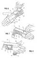
- FIGS. 2-4are three top plan views illustrating a strap spread out in three consecutive stages of processing for production of a product according to a first embodiment of the invention which provides a wrist splint;
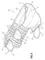
- FIG. 5is a perspective view illustrating the last stage of production of the wrist splint according to the invention.
- FIGS. 6-8are three perspective views illustrating the wrist splint of FIG. 5 in the stages of application and removal from the wearer's wrist;
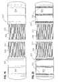
- FIGS. 9-11are three plan views illustrating a spread-out strap during three successive stages of production of a product according to a second embodiment of the invention which provides a wrist support;
- FIG. 12is a perspective view illustrating the final stage of production of the wrist support according to the invention.
- FIGS. 13-15are three perspective views illustrating the wrist support of FIG. 12 in the stages of application to a wearer's wrist;
- FIG. 16is a top plan view illustrating a spread-out strap for realization of a portion of knee support according to a third embodiment of the invention.
- FIG. 17is a perspective view illustrating the portion of knee support obtained with the strap of FIG. 16 , disposed in an open position;
- FIG. 18is a perspective view illustrating the portion of knee support in FIG. 17 , in the closed position
- FIGS. 19 and 20are top plan views illustrating respectively two spread-out straps during two stages of production of a corset according to a fourth embodiment of the invention.
- FIG. 21is a perspective view illustrating a corset obtained with the straps of FIGS. 19 and 20 .
- FIGS. 1-8a first embodiment of a product according to the invention, in the form of a wrist splint, illustrated as a whole in FIG. 5 and denoted by reference numeral 20 , will now be described.
- the multilayer sheet 1is made up of several layers of material coupled to one another. Flame bonding is preferably used.
- the multilayer sheet 1comprises:
- the bottom layer 2being in contact with the skin, must be made of anallergic material, such as cotton fabric.
- the intermediate layer 3must be made of a cushioning, breathable material, such as, for example, open-cell foamed plastic material such as polyurethane. (PU).
- PUpolyurethane.
- the top layer 4must have a top surface 40 suitable for a Velcro-type coupling. Therefore, the top surface 40 of the top layer 4 has a plurality of loops able to couple in a fastening relationship with a plurality of matching hooks of a Velcro-type fastening element, as will be described hereunder.
- the top layer 4can be made of nylon fabric suitably treated so as to obtain an upper surface 40 with a plurality of loops.
- Flame bonding of the multilayer sheet 1takes place by feeding from two respective rolls the bottom layer 2 and the intermediate layer 3 , which is made to pass near a flame which heats it on the surface facing the bottom layer 2 to allow bonding thereof. Then, the two layers 2 and 3 are made to pass through a calender which performs bonding. Subsequently, the outside of the intermediate layer 3 is heated by means of a flame and bonded by means of a calender with the top layer 4 fed from a roll.
- the intermediate layer 3made of PU, allows good adhesion with the bottom layer 2 and the top layer 4 , by means of flame bonding.
- Flame bondingis an example of the types of coupling that can be made between materials.
- Alternatively there are other methodssuch as spread or sprayed glue, hot glue, etc.
- the multi-layer sheet 1having a substantially rectangular shape, is fed through a die-punching and pressure moulding machine. Then, the multilayer sheet 1 is compressed between two mould halves which simultaneously perform die-punching and moulding along the pre-established perimeter, so as to obtain a strap 5 , as shown in FIG. 2 .
- the strap 5comprises a substantially rectangular central portion 6 .
- the longer sides of the central portion 6follow the longitudinal direction of the strap 5 ; on the contrary, the shorter sides of the central portion 6 follow the cross direction of the strap 5 .
- the side band 7 and the laces 8 , 8 ′extend in the crosswise direction of the strap 5 .
- the laces 8 , 8 ′are eight in number and the first four laces 8 starting from the side band 7 have a slightly shorter length than the other four laces 8 ′.
- a slot 9is formed by die-punching and is of such a size as to allow insertion of the thumb of a hand.
- the slot 9extends in the lengthwise direction of the strap 5 .
- pressure mouldingis performed all along the outer peripheral edge of the central portion 6 , the side band 7 and the laces 8 , 8 ′ and also all along the peripheral edge of the slot 9 .
- Hot mouldingis preferably performed, so as to obtain heat welding or thermoforming of the intermediate layer 3 to the bottom and top layers 2 and 4 , along the peripheral edge.
- the intermediate layer 3must be of heat-weldable material, such as polyurethane for example.
- ultrasound weldingusing a mould half vibrating at the frequency of ultrasound can be used.
- two longitudinal pockets 10are applied by sewing.
- a longitudinal reinforcing strip 11is sewn.
- the pockets 10 and the reinforcing strip 11are preferably made of the same material as the top layer 4 , or in any case of a material suitable to allow Velcro-type fastening.
- a plurality of eyelets 13are made in the reinforcing strip by die-punching, in a number equal to that of the laces 8 , 8 ′ and in a position coinciding with said laces 8 , 8 ′, in a crosswise direction.
- the eyelets 13are wide enough to accommodate the respective laces 8 , 8 ′.
- the laces 8 , 8 ′are inserted in the respective eyelets 13 and pulled so that the strap 5 takes on a substantially tubular shape.
- Velcro-type fastening elements 15are applied to the strap 5 , by means of sewing 14 .
- a first fastening element 15is applied to the free end of the group of four longer laces 8 ′
- a second fastening element 15is applied to the free end of the group of four shorter laces 8
- a third fastening element 15is applied to the end of the side band 7 .
- Each fastening element 15is shaped like a substantially semi-elliptical patch of such a size as to be able to be gripped easily by the wearer.
- the fastening element 15has two end flaps 17 , disposed in a substantially V-shaped configuration, to be sewn to the ends of the laces 8 , 8 ′ and of the side band 7 .
- the wrist splint 20illustrated in FIG. 5 , is obtained, ready to be worn on the wrist of a wearer.
- the splint 20is fitted on the wrist of the wearer so that the thumb of the hand enters the slot 9 of the splint. Subsequently, the wearer, with the other hand, grips the first fastening element 15 so as to tighten the group of four longer laces 8 ′ as much as possible and thus block the fastening element 15 on the upper surface 40 of the strap 5 ; then the second fastening element 15 is gripped so as to tighten the group of four shorter laces 8 as much as possible and thus block the fastening element 15 on the upper surface 40 of the strap 5 ; and lastly the third fastening element 15 is gripped so as to tighten the side band 7 as much as possible and thus block the fastening element 15 on the upper surface 40 of the strap 5 .
- the wearerdisengages the fastening elements 15 and loosens the laces 8 , 8 ′ to remove the splint 20 from the wrist.
- the undersurface of the laces 8 , 8 ′can come into contact with the wearer's skin. This is not a problem since the undersurface of the laces is made of the same anallergic material as the undersurface of the strap 5 .
- FIGS. 9-15Another product according to a second embodiment of the invention, which provides a wrist brace, illustrated as a whole in FIG. 12 and indicated with reference numeral 120 , is described with the aid of FIGS. 9-15 .
- This sheetis fed toward a die-punching and moulding machine to be die-punched and moulded along its peripheral edge so as to obtain a strap 105 having the shape illustrated in FIG. 9 .
- the strap 105comprises a substantially rectangular main portion 106 destined to surround the wearer's wrist.
- a reinforcing strip 111disposed near the opposite side to that in which the laces 108 , 108 ′ is sewn onto the main portion 106 of the strap 105 .
- a plurality of eyelets 113 , 113 ′are made, by die-punching, coinciding with the laces 108 , 108 ′ and able to accommodate said laces.
- three eyelets 113are aligned near the opposite side to the laces and another three eyelets 113 ′ are aligned slightly more towards the inside with respect to the three eyelets 113 .
- the shorter laces 108engage in the outermost eyelets 113 ; the longer laces 108 ′, on the other hand, engage in the innermost eyelets 113 ′.
- a Velcro-type fastening element 15is fixed, by means of sewing 14 , to the free ends of the laces 108 , 108 ′.
- the fastening element 15is substantially similar to that described in the first embodiment and has on one surface a plurality of hooks 16 able to engage, in a fastening relationship, with the loops 40 provided on the upper surface of the strap 105 .
- a third embodiment of the inventionwhich provides a portion of knee brace, illustrated as a whole in FIGS. 17 and 18 and denoted by reference numeral 220 , is described with the aid of FIGS. 16-18 .
- This sheetis fed toward a die-punching and moulding machine to be die-punched and moulded along its peripheral edge so as to obtain a strap 205 having the shape illustrated in FIG. 16 .
- the strap 205comprises a substantially rectangular portion 206 destined to surround a part of the wearer's knee.
- ten laces 208 which protrude toward the right and nine laces 208 ′ which protrude toward the leftare provided.
- the right and left laces 208 , 208 ′are of the same length and disposed offset from each other, so that a space 213 having a width equal to the width of the lace is formed between two adjacent laces.
- the right-hand laces 208are inserted in the spaces 213 defined between the left-hand laces 208 ′, whilst the left-hand laces 208 ′ are inserted in the spaces 213 defined between right-hand laces 208 .
- two fastening elements 15 of the Velcro typeare fixed to the free end of the right-hand laces 208 , and left-hand laces 208 ′.
- FIG. 21A fourth embodiment of the invention which provides for a corset, illustrated as a whole in FIG. 21 and denoted with reference numeral 320 , is described with the aid of FIGS. 19-21 .
- This sheetis fed toward a die-punching and moulding machine to be die-punched and moulded along its peripheral edge so as to obtain two straps 205 , 305 ′, substantially the same, having the shapes illustrated in FIG. 19 .
- Each strap 205 , 305comprises a substantially rectangular central portion 306 .
- ten laces 208are provide on each surface 305 , 305 ′.
- reinforcing strips 310are sewn onto the top surface of each strap 305 , 305 ′.
- the laces 308 of a strapare inserted into the spaces 313 of the other strap 305 ′. Subsequently, four fastening elements 15 of the Velcro type, substantially similar to those previously described, are fixed to the ends of the four groups of five laces 308 .
- a strip 315 of a Velcro-type fastening elementwhich provides a plurality of hooks 16 able to couple with the loops 40 provided on the outer surface of the top layer 4 of the strap 205 , is applied by sewing.
Landscapes
- Health & Medical Sciences (AREA)
- Nursing (AREA)
- Orthopedic Medicine & Surgery (AREA)
- Engineering & Computer Science (AREA)
- Biomedical Technology (AREA)
- Heart & Thoracic Surgery (AREA)
- Vascular Medicine (AREA)
- Life Sciences & Earth Sciences (AREA)
- Animal Behavior & Ethology (AREA)
- General Health & Medical Sciences (AREA)
- Public Health (AREA)
- Veterinary Medicine (AREA)
- Orthopedics, Nursing, And Contraception (AREA)
- Professional, Industrial, Or Sporting Protective Garments (AREA)
Abstract
Description
- thumb splints: indicated for dislocations, strains and fractures of the thumb or also for lesions of the thumb ligament in sports injuries;
- wrist splints: indicated for dislocations and sprains of the wrist and for carpal tunnel syndrome;
- wrist braces: indicated for dislocations, slight lesions and small injuries of the wrist;
- epicondylitis straps: indicated for radial and/or medial epicondylitis and tendinitis of the elbow;
- corsets: indicated for mild spinal injuries;
- thigh braces: indicated for contractures, pulls and sprains of the quadriceps muscle;
- knee braces: indicated for injuries of the knee joints;
- ankle braces: particularly indicated in control of ankle eversion and inversion of the ankle; and
- elastic ankle supports: indicated after mild tibio-tarsal injuries.
- a bottom layer, of anallegic material, destined to come into contact with the skin of the wearer,
- a top layer of material suitable for Velcro-type fastening (mutually engageable hooks and loops), and
- an intermediate layer of padding consisting of a soft, breathable material.
- a
bottom layer 2 destined to come into contact with the wearer's skin, - an intermediate layer of
padding 3, and - a
top layer 4 destined to face outward.
- a
Claims (10)
Applications Claiming Priority (4)
| Application Number | Priority Date | Filing Date | Title |
|---|---|---|---|
| ITMI2004A1810 | 2004-09-22 | ||
| IT001810AITMI20041810A1 (en) | 2004-09-22 | 2004-09-22 | "SANITARY ITEM, EVEN FOR SPORTS USE, AND RELATED PRODUCTION METHOD" |
| ITMI2004A001810 | 2004-09-22 | ||
| PCT/EP2005/008597WO2006032325A1 (en) | 2004-09-22 | 2005-08-08 | Medical product, also for sports use, and relative manufacturing method |
Publications (2)
| Publication Number | Publication Date |
|---|---|
| US20080119771A1 US20080119771A1 (en) | 2008-05-22 |
| US7874997B2true US7874997B2 (en) | 2011-01-25 |
Family
ID=35058703
Family Applications (1)
| Application Number | Title | Priority Date | Filing Date |
|---|---|---|---|
| US11/663,195Expired - Fee RelatedUS7874997B2 (en) | 2004-09-22 | 2005-08-08 | Medical product, also for sports use, and relative manufacturing method |
Country Status (3)
| Country | Link |
|---|---|
| US (1) | US7874997B2 (en) |
| IT (1) | ITMI20041810A1 (en) |
| WO (1) | WO2006032325A1 (en) |
Cited By (27)
| Publication number | Priority date | Publication date | Assignee | Title |
|---|---|---|---|---|
| US20100010407A1 (en)* | 2007-02-27 | 2010-01-14 | Sports & Supports Limited | Splint, particularly for the wrist, and production method therefor |
| US20110130694A1 (en)* | 2009-07-02 | 2011-06-02 | Djo, Llc | Adjustable wrist brace |
| US20130138734A1 (en)* | 2011-11-29 | 2013-05-30 | Frank Crivello | Interactive training method and system for developing peak user performance |
| USD687556S1 (en)* | 2012-02-14 | 2013-08-06 | Exos Corporation | BOXER'S fracture brace |
| US8597215B2 (en) | 2007-04-09 | 2013-12-03 | Covidien Lp | Compression device with structural support features |
| US8622942B2 (en) | 2007-04-09 | 2014-01-07 | Covidien Lp | Method of making compression sleeve with structural support features |
| US8632840B2 (en) | 2008-09-30 | 2014-01-21 | Covidien Lp | Compression device with wear area |
| US8721575B2 (en) | 2007-04-09 | 2014-05-13 | Covidien Lp | Compression device with s-shaped bladder |
| US8740828B2 (en) | 2007-04-09 | 2014-06-03 | Covidien Lp | Compression device with improved moisture evaporation |
| US8951217B2 (en) | 2009-02-24 | 2015-02-10 | Exos Llc | Composite material for custom fitted products |
| US9084713B2 (en) | 2007-04-09 | 2015-07-21 | Covidien Lp | Compression device having cooling capability |
| US9114052B2 (en) | 2007-04-09 | 2015-08-25 | Covidien Lp | Compression device with strategic weld construction |
| US9205021B2 (en) | 2012-06-18 | 2015-12-08 | Covidien Lp | Compression system with vent cooling feature |
| US9295748B2 (en) | 2012-07-31 | 2016-03-29 | Exos Llc | Foam core sandwich splint |
| US9364037B2 (en) | 2005-07-26 | 2016-06-14 | Covidien Ag | Limited durability fastening for a garment |
| US9387146B2 (en) | 2007-04-09 | 2016-07-12 | Covidien Lp | Compression device having weld seam moisture transfer |
| US20160213548A1 (en)* | 2015-01-28 | 2016-07-28 | Panasonic Intellectual Property Management Co., Ltd. | Assist garment, method for controlling controller of assist garment, and recording medium |
| US9408738B2 (en) | 2012-08-01 | 2016-08-09 | Exos Llc | Orthopedic brace for animals |
| US9561128B2 (en) | 2007-06-20 | 2017-02-07 | Exos Llc | Orthopedic system for immobilizing and supporting body parts |
| US9655761B2 (en) | 2012-11-12 | 2017-05-23 | Djo, Llc | Orthopedic back brace |
| US9872792B2 (en)* | 2012-02-10 | 2018-01-23 | Ossur Hf | Wrist brace and method and components for securing the same |
| US10231861B1 (en)* | 2015-03-04 | 2019-03-19 | Paul J. Stafford | Physical training device |
| US11304479B2 (en)* | 2017-02-28 | 2022-04-19 | Nike, Inc. | Footwear with laceless fastening system |
| US11490690B2 (en) | 2019-07-26 | 2022-11-08 | Nike, Inc. | Footwear upper with magnetic hold open for foot entry |
| US11523660B2 (en) | 2018-04-13 | 2022-12-13 | Nike, Inc. | Footwear fastening system |
| US11553760B2 (en) | 2019-07-26 | 2023-01-17 | Nike, Inc. | Closure strap for footwear upper with looped grab handle |
| US12403029B1 (en) | 2020-03-04 | 2025-09-02 | Preferred Prescription, Inc. | Dual-handed wrist brace with enhanced thumb support |
Families Citing this family (14)
| Publication number | Priority date | Publication date | Assignee | Title |
|---|---|---|---|---|
| US7871387B2 (en) | 2004-02-23 | 2011-01-18 | Tyco Healthcare Group Lp | Compression sleeve convertible in length |
| US8029451B2 (en) | 2005-12-12 | 2011-10-04 | Tyco Healthcare Group Lp | Compression sleeve having air conduits |
| US8016778B2 (en) | 2007-04-09 | 2011-09-13 | Tyco Healthcare Group Lp | Compression device with improved moisture evaporation |
| US8029450B2 (en) | 2007-04-09 | 2011-10-04 | Tyco Healthcare Group Lp | Breathable compression device |
| US8021388B2 (en) | 2007-04-09 | 2011-09-20 | Tyco Healthcare Group Lp | Compression device with improved moisture evaporation |
| DE202008004212U1 (en)* | 2008-03-27 | 2009-08-13 | Hallufix Ag | support bandage |
| US8235923B2 (en) | 2008-09-30 | 2012-08-07 | Tyco Healthcare Group Lp | Compression device with removable portion |
| NL1036870C2 (en)* | 2009-04-17 | 2010-10-19 | Ten Cate Itex B V | DEVICE FOR MANUFACTURING A FIBER MAT BY WEAVING. |
| US8652079B2 (en) | 2010-04-02 | 2014-02-18 | Covidien Lp | Compression garment having an extension |
| US10751221B2 (en) | 2010-09-14 | 2020-08-25 | Kpr U.S., Llc | Compression sleeve with improved position retention |
| CN104720945B (en)* | 2015-03-31 | 2018-01-16 | 泰山医学院 | A kind of ankle joint orthotic device |
| US10350104B2 (en)* | 2015-07-15 | 2019-07-16 | Scott Specialties, Inc. | Orthopedic brace and method of making the same |
| US10772753B2 (en) | 2015-11-20 | 2020-09-15 | Medical Specialties, Inc. | Universal wrist brace with enhanced lacing |
| CA2948906A1 (en) | 2015-11-20 | 2017-05-20 | Eric Lee Gaylord | Wrist brace with enhanced lacing |
Citations (14)
| Publication number | Priority date | Publication date | Assignee | Title |
|---|---|---|---|---|
| US2206404A (en)* | 1938-04-25 | 1940-07-02 | Walter J Jones | Wrist splint |
| US4176839A (en) | 1977-05-02 | 1979-12-04 | Pinkus Alan E | Wrist support |
| US4825856A (en)* | 1988-02-05 | 1989-05-02 | Nelson Ronald E | Reinforced ankle and foot brace |
| EP0368583A1 (en)* | 1988-11-05 | 1990-05-16 | Seton Healthcare Group plc | Post-operative support belt |
| US5160314A (en)* | 1991-04-26 | 1992-11-03 | Bissell Healthcare Co. | Wrist support |
| US5221252A (en)* | 1991-10-15 | 1993-06-22 | Tru-Fit Marketing Corp. | Adjustable knee support |
| US5695452A (en) | 1993-02-16 | 1997-12-09 | Grim; Tracy E. | Formed resilient orthopaedic device |
| US5769804A (en)* | 1996-07-26 | 1998-06-23 | Becton Dickinson And Company | Carpal tunnel syndrome wrist brace |
| US5865777A (en) | 1998-05-01 | 1999-02-02 | Detty; Gerald D. | Geriatric knee brace |
| US6042557A (en) | 1998-06-10 | 2000-03-28 | K.R. Ferguson Technologies, Inc. | Orthopedic splints and methods of making same |
| US6488643B1 (en)* | 1998-10-08 | 2002-12-03 | Kci Licensing, Inc. | Wound healing foot wrap |
| US6572600B1 (en) | 2000-02-15 | 2003-06-03 | The Procter & Gamble Company | Disposable article with deactivatable adhesive |
| US6893410B1 (en)* | 2002-12-04 | 2005-05-17 | Weber Orthopedic Inc. | Multi-adjustable wrist brace |
| US20050142334A1 (en)* | 2002-01-30 | 2005-06-30 | Saburo Mikata | Orthotic apparatus and sheet with laminated structure |
- 2004
- 2004-09-22ITIT001810Apatent/ITMI20041810A1/enunknown
- 2005
- 2005-08-08WOPCT/EP2005/008597patent/WO2006032325A1/enactiveApplication Filing
- 2005-08-08USUS11/663,195patent/US7874997B2/ennot_activeExpired - Fee Related
Patent Citations (14)
| Publication number | Priority date | Publication date | Assignee | Title |
|---|---|---|---|---|
| US2206404A (en)* | 1938-04-25 | 1940-07-02 | Walter J Jones | Wrist splint |
| US4176839A (en) | 1977-05-02 | 1979-12-04 | Pinkus Alan E | Wrist support |
| US4825856A (en)* | 1988-02-05 | 1989-05-02 | Nelson Ronald E | Reinforced ankle and foot brace |
| EP0368583A1 (en)* | 1988-11-05 | 1990-05-16 | Seton Healthcare Group plc | Post-operative support belt |
| US5160314A (en)* | 1991-04-26 | 1992-11-03 | Bissell Healthcare Co. | Wrist support |
| US5221252A (en)* | 1991-10-15 | 1993-06-22 | Tru-Fit Marketing Corp. | Adjustable knee support |
| US5695452A (en) | 1993-02-16 | 1997-12-09 | Grim; Tracy E. | Formed resilient orthopaedic device |
| US5769804A (en)* | 1996-07-26 | 1998-06-23 | Becton Dickinson And Company | Carpal tunnel syndrome wrist brace |
| US5865777A (en) | 1998-05-01 | 1999-02-02 | Detty; Gerald D. | Geriatric knee brace |
| US6042557A (en) | 1998-06-10 | 2000-03-28 | K.R. Ferguson Technologies, Inc. | Orthopedic splints and methods of making same |
| US6488643B1 (en)* | 1998-10-08 | 2002-12-03 | Kci Licensing, Inc. | Wound healing foot wrap |
| US6572600B1 (en) | 2000-02-15 | 2003-06-03 | The Procter & Gamble Company | Disposable article with deactivatable adhesive |
| US20050142334A1 (en)* | 2002-01-30 | 2005-06-30 | Saburo Mikata | Orthotic apparatus and sheet with laminated structure |
| US6893410B1 (en)* | 2002-12-04 | 2005-05-17 | Weber Orthopedic Inc. | Multi-adjustable wrist brace |
Cited By (45)
| Publication number | Priority date | Publication date | Assignee | Title |
|---|---|---|---|---|
| US9364037B2 (en) | 2005-07-26 | 2016-06-14 | Covidien Ag | Limited durability fastening for a garment |
| US8388563B2 (en)* | 2007-02-27 | 2013-03-05 | Sports & Supports Limited | Splint, particularly for the wrist, and production method therefor |
| US20100010407A1 (en)* | 2007-02-27 | 2010-01-14 | Sports & Supports Limited | Splint, particularly for the wrist, and production method therefor |
| US9107793B2 (en) | 2007-04-09 | 2015-08-18 | Covidien Lp | Compression device with structural support features |
| US9114052B2 (en) | 2007-04-09 | 2015-08-25 | Covidien Lp | Compression device with strategic weld construction |
| US9387146B2 (en) | 2007-04-09 | 2016-07-12 | Covidien Lp | Compression device having weld seam moisture transfer |
| US8597215B2 (en) | 2007-04-09 | 2013-12-03 | Covidien Lp | Compression device with structural support features |
| US8622942B2 (en) | 2007-04-09 | 2014-01-07 | Covidien Lp | Method of making compression sleeve with structural support features |
| US9808395B2 (en) | 2007-04-09 | 2017-11-07 | Covidien Lp | Compression device having cooling capability |
| US8721575B2 (en) | 2007-04-09 | 2014-05-13 | Covidien Lp | Compression device with s-shaped bladder |
| US8740828B2 (en) | 2007-04-09 | 2014-06-03 | Covidien Lp | Compression device with improved moisture evaporation |
| US9084713B2 (en) | 2007-04-09 | 2015-07-21 | Covidien Lp | Compression device having cooling capability |
| US8992449B2 (en) | 2007-04-09 | 2015-03-31 | Covidien Lp | Method of making compression sleeve with structural support features |
| US10463544B2 (en) | 2007-06-20 | 2019-11-05 | Djo, Llc | Orthopedic system for immobilizing and supporting body parts |
| US9561128B2 (en) | 2007-06-20 | 2017-02-07 | Exos Llc | Orthopedic system for immobilizing and supporting body parts |
| US10137052B2 (en) | 2008-04-07 | 2018-11-27 | Kpr U.S., Llc | Compression device with wear area |
| US8632840B2 (en) | 2008-09-30 | 2014-01-21 | Covidien Lp | Compression device with wear area |
| US8951217B2 (en) | 2009-02-24 | 2015-02-10 | Exos Llc | Composite material for custom fitted products |
| US9757265B2 (en) | 2009-02-24 | 2017-09-12 | Djo, Llc | Composite material for custom fitted products |
| US10940031B2 (en) | 2009-02-24 | 2021-03-09 | Djo, Llc | Composite material for custom fitted products |
| US8147438B2 (en)* | 2009-07-02 | 2012-04-03 | Djo, Llc | Adjustable wrist brace |
| US20110130694A1 (en)* | 2009-07-02 | 2011-06-02 | Djo, Llc | Adjustable wrist brace |
| US9087454B2 (en)* | 2011-11-29 | 2015-07-21 | At Peak Resources, Llc | Interactive training method and system for developing peak user performance |
| US20130138734A1 (en)* | 2011-11-29 | 2013-05-30 | Frank Crivello | Interactive training method and system for developing peak user performance |
| US9872792B2 (en)* | 2012-02-10 | 2018-01-23 | Ossur Hf | Wrist brace and method and components for securing the same |
| USD687556S1 (en)* | 2012-02-14 | 2013-08-06 | Exos Corporation | BOXER'S fracture brace |
| US9205021B2 (en) | 2012-06-18 | 2015-12-08 | Covidien Lp | Compression system with vent cooling feature |
| US10966856B2 (en) | 2012-07-31 | 2021-04-06 | Djo, Llc | Foam core sandwich splint |
| US9295748B2 (en) | 2012-07-31 | 2016-03-29 | Exos Llc | Foam core sandwich splint |
| US10285845B2 (en) | 2012-07-31 | 2019-05-14 | Djo, Llc | Foam core sandwich splint |
| US9408738B2 (en) | 2012-08-01 | 2016-08-09 | Exos Llc | Orthopedic brace for animals |
| US11191627B2 (en) | 2012-08-01 | 2021-12-07 | Djo, Llc | Orthopedic brace for animals |
| US11484429B2 (en) | 2012-11-12 | 2022-11-01 | Djo, Llc | Orthopedic back brace |
| US10517749B2 (en) | 2012-11-12 | 2019-12-31 | Djo, Llc | Orthopedic back brace |
| US9655761B2 (en) | 2012-11-12 | 2017-05-23 | Djo, Llc | Orthopedic back brace |
| US10561565B2 (en)* | 2015-01-28 | 2020-02-18 | Panasonic Intellectual Property Management Co., Ltd. | Assist garment, method for controlling controller of assist garment, and recording medium |
| US20160213548A1 (en)* | 2015-01-28 | 2016-07-28 | Panasonic Intellectual Property Management Co., Ltd. | Assist garment, method for controlling controller of assist garment, and recording medium |
| US11445769B2 (en) | 2015-01-28 | 2022-09-20 | Panasonic Intellectual Property Management Co., Ltd. | Assist garment, method for controlling controller of assist garment, and recording medium |
| US10231861B1 (en)* | 2015-03-04 | 2019-03-19 | Paul J. Stafford | Physical training device |
| US11304479B2 (en)* | 2017-02-28 | 2022-04-19 | Nike, Inc. | Footwear with laceless fastening system |
| US11523660B2 (en) | 2018-04-13 | 2022-12-13 | Nike, Inc. | Footwear fastening system |
| US11707114B2 (en) | 2018-04-13 | 2023-07-25 | Nike, Inc. | Footwear fastening system |
| US11490690B2 (en) | 2019-07-26 | 2022-11-08 | Nike, Inc. | Footwear upper with magnetic hold open for foot entry |
| US11553760B2 (en) | 2019-07-26 | 2023-01-17 | Nike, Inc. | Closure strap for footwear upper with looped grab handle |
| US12403029B1 (en) | 2020-03-04 | 2025-09-02 | Preferred Prescription, Inc. | Dual-handed wrist brace with enhanced thumb support |
Also Published As
| Publication number | Publication date |
|---|---|
| ITMI20041810A1 (en) | 2004-12-22 |
| US20080119771A1 (en) | 2008-05-22 |
| WO2006032325A1 (en) | 2006-03-30 |
Similar Documents
| Publication | Publication Date | Title |
|---|---|---|
| US7874997B2 (en) | Medical product, also for sports use, and relative manufacturing method | |
| US10940031B2 (en) | Composite material for custom fitted products | |
| US6582382B2 (en) | Orthopedic supports | |
| US7765619B2 (en) | Corset | |
| US6394971B1 (en) | Ankle brace and support and method | |
| US8007454B1 (en) | Ankle support assembly and method of supporting an ankle | |
| US20070237808A1 (en) | Therapeutic belt | |
| CN111511315B (en) | Orthotics used to immobilize joints | |
| EP0005615A1 (en) | A protective device for parts of the body | |
| AU2016347778B2 (en) | Bandage for immobilising or holding a joint | |
| JPH04120719U (en) | ankle orthosis | |
| CA2676285C (en) | Splint, particularly for the wrist, and production method therefor | |
| CA2540145C (en) | Dual tensioning health support | |
| US12318323B1 (en) | Extendable fracture orthosis | |
| US11819439B1 (en) | Wrist brace with welded thumb spica and method for making same | |
| WO2004017874A1 (en) | Orthopedic supports | |
| AU2002307834A1 (en) | Orthopedic supports |
Legal Events
| Date | Code | Title | Description |
|---|---|---|---|
| AS | Assignment | Owner name:SPORTS & SUPPORTS LTD., IRELAND Free format text:ASSIGNMENT OF ASSIGNORS INTEREST;ASSIGNOR:JACCARD, JEAN-PATRICK;REEL/FRAME:019078/0499 Effective date:20070308 | |
| STCF | Information on status: patent grant | Free format text:PATENTED CASE | |
| FPAY | Fee payment | Year of fee payment:4 | |
| AS | Assignment | Owner name:ANTARCTIC HOLDING COMPANY INC., DELAWARE Free format text:ASSIGNMENT OF ASSIGNORS INTEREST;ASSIGNOR:SPORTS & SUPPORTS LIMITED;REEL/FRAME:037159/0291 Effective date:20140930 Owner name:INDACO S.R.L., ITALY Free format text:ASSIGNMENT OF ASSIGNORS INTEREST;ASSIGNOR:ANTARCTIC HOLDING COMPANY INC.;REEL/FRAME:037476/0963 Effective date:20141027 | |
| MAFP | Maintenance fee payment | Free format text:PAYMENT OF MAINTENANCE FEE, 8TH YR, SMALL ENTITY (ORIGINAL EVENT CODE: M2552) Year of fee payment:8 | |
| FEPP | Fee payment procedure | Free format text:MAINTENANCE FEE REMINDER MAILED (ORIGINAL EVENT CODE: REM.); ENTITY STATUS OF PATENT OWNER: SMALL ENTITY | |
| LAPS | Lapse for failure to pay maintenance fees | Free format text:PATENT EXPIRED FOR FAILURE TO PAY MAINTENANCE FEES (ORIGINAL EVENT CODE: EXP.); ENTITY STATUS OF PATENT OWNER: SMALL ENTITY | |
| STCH | Information on status: patent discontinuation | Free format text:PATENT EXPIRED DUE TO NONPAYMENT OF MAINTENANCE FEES UNDER 37 CFR 1.362 | |
| FP | Lapsed due to failure to pay maintenance fee | Effective date:20230125 |