US7874743B2 - Pressure equalizing equipment housing - Google Patents
Pressure equalizing equipment housingDownload PDFInfo
- Publication number
- US7874743B2 US7874743B2US11/667,989US66798905AUS7874743B2US 7874743 B2US7874743 B2US 7874743B2US 66798905 AUS66798905 AUS 66798905AUS 7874743 B2US7874743 B2US 7874743B2
- Authority
- US
- United States
- Prior art keywords
- pressure equalizing
- enclosure
- pressure
- chamber
- sealed enclosure
- Prior art date
- Legal status (The legal status is an assumption and is not a legal conclusion. Google has not performed a legal analysis and makes no representation as to the accuracy of the status listed.)
- Expired - Fee Related, expires
Links
Images


Classifications
- H—ELECTRICITY
- H05—ELECTRIC TECHNIQUES NOT OTHERWISE PROVIDED FOR
- H05K—PRINTED CIRCUITS; CASINGS OR CONSTRUCTIONAL DETAILS OF ELECTRIC APPARATUS; MANUFACTURE OF ASSEMBLAGES OF ELECTRICAL COMPONENTS
- H05K5/00—Casings, cabinets or drawers for electric apparatus
- H05K5/06—Hermetically-sealed casings
- H05K5/068—Hermetically-sealed casings having a pressure compensation device, e.g. membrane
Definitions
- the present inventionrelates to equipment housings and more particularly, to a pressure equalizing equipment housing that prevents condensation on the inside of the housing.
- Equipmentsuch as a mechanical or electrical device may not function properly if it is subjected to moisture or condensation. Enclosures may protect such devices from dripping water on the outside but may not prevent direct condensation from forming inside the enclosure, for example, during extreme temperature cycling.
- the inside walls of the enclosuremay cool and the air inside may eventually cool.
- the relative pressure inside the enclosuremay drop, drawing external air into the enclosure (e.g., through leaks in the enclosure).
- the external airmay be near 100% relative humidity, for example, when the enclosure is rapidly cooled in a rainstorm.
- the relative humidity of the air inside the enclosuremay eventually reach the relative humidity of the air outside the enclosure, and when cooled further, may cause condensation inside of the enclosure.
- a video dome enclosuremay be mounted above an area of interest and may have an optically clear or transparent bubble forming the bottom half of the enclosure.
- An integral pan-tilt-zoom mechanismmay be used to observe the area of interest (e.g., parking lots, security gates, building entrances and etc.) usually below and to the sides of the dome.
- Existing outdoor video dome enclosuresmay have a condensation problem, especially when located in a coastal humid environment. Condensation on the inside or outside of the bubble may render the dome useless. Condensation on the inside may form a haze on the bubble that obscures the view and may also collect into droplets that run down into the bottom of the bubble to obscure the view.
- the life of the electronics and mechanical components in the enclosuremay also be shortened through corrosion caused by condensation.
- Sealed enclosureshave been designed to prevent air from entering. Sealed enclosures may leak, however, when subjected to relatively high differential pressures between the inside and outside of the enclosure. Sealed enclosures may be even more difficult to seal when cables need to be run through the walls of the enclosure. A hermetically sealed enclosure solution may work under ideal conditions, but in many cases, is too cost prohibitive and unreliable.
- FIG. 1is a partial cross-sectional view of a pressure equalizing equipment housing, consistent with one embodiment of the present invention.
- FIGS. 2A-2Care partial cross-sectional views of a pressure equalization device, consistent with one embodiment of the present invention, in various states of expansion.
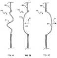
- FIGS. 3A-3Care cross-sectional views of a pressure equalization device, consistent with another embodiment of the present invention, in various states of expansion.
- a pressure equalizing equipment housing 100may be used to house equipment including one or more mechanical devices and/or electronic devices.
- the pressure equalizing equipment housing 100provides pressure equalization between an internal pressure inside of a sealed enclosure 102 and an ambient pressure outside of the housing 100 .
- the internal pressure inside of the sealed enclosure 102will not be higher or lower than the ambient pressure outside of the housing 100 . Maintaining pressure equalization with the surrounding atmosphere thus minimizes or eliminates pressure differentials that may cause leaks through the sealed enclosure 102 . Minimizing leaks into and out of the sealed enclosure 102 may thus reduce the possibility of condensation inside of the sealed enclosure 102 .
- the sealed enclosure 102 of the pressure equalizing equipment housing 100encloses equipment 104 within an interior region 106 .
- the pressure equalizing equipment housing 100may also include a pressure equalization device 110 defining a volumetrically adjustable chamber 112 configured to expand and contract to change its volume.
- the pressure equalization device 110may be coupled to the sealed enclosure 102 by way of a sealed fluid connection such that air or gas flows freely between the interior region 106 and the chamber 112 , allowing the chamber 112 to expand and contract.
- the internal gasWhen the temperature inside the sealed enclosure 102 increases, the internal gas will try to expand. If it were not permitted to expand the internal pressure would increase with respect to ambient pressure. Similarly, when the temperature inside the sealed enclosure 102 decreases, the internal gas will try to contract, lowering the relative pressure. Changes in the ambient atmospheric pressure also cause a pressure differential. Relative pressure differential caused by ambient temperature changes may be four (4) times those due to atmospheric pressure changes alone. The pressure equalizing equipment housing 100 may compensates for pressure differential caused by both ambient temperature changes and atmospheric pressure changes.
- a higher pressure outside the housing 100causes the volumetrically adjustable chamber 112 to contract and decreases the volume of the chamber 112 , causing air or gas to flow from the chamber 112 into the interior region 106 (e.g., in the direction of arrow 10 ) until the pressure is equalized.
- a higher pressure inside the sealed enclosure 102causes the volumetrically adjustable chamber 112 to expand and increases the volume of the chamber 112 , causing air or gas to flow from the interior region 106 into the chamber 112 (e.g., in the direction of arrow 12 ) until the pressure is equalized.
- the internal pressure within the sealed enclosure 102may be continually equalized with the ambient pressure, which minimizes the pressure differentials that may cause leaks.
- the same recycled air or trapped gas within the enclosure 102flows into and out of the pressure equalizing device 110 as the ambient pressure changes, instead of air or gas flowing between the sealed enclosure 102 and the surrounding environment.
- the pressure equalization device 110may be configured such that the volume of the volumetrically adjustable chamber 112 is capable of changing to a degree that will accommodate relative ambient pressure changes.
- the volumetrically adjustable chamber 112may allow enough contraction to adjust to the highest expected increases in relative ambient pressure and may allow enough expansion to adjust to the highest expected decreases in relative ambient pressure.
- the volumetrically adjustable chamber 112is designed to allow a volumetric change of about 50% to accommodate ambient pressure changes in a range of about 6% and ambient temperature changes over a range of about ⁇ 40° C. to +50° C.
- the pressure equalization device 110may be installed (e.g., coupled to the sealed enclosure 102 ) with the volumetrically adjustable chamber 112 in a non-pressurized state and with an initial volume that allows the desired expansion or contraction.
- the pressure equalization device 110may include a flexible container 114 (e.g., a flat bag type bladder) that defines the chamber 112 .
- the flexible container 114may be made of a flexible or compliant material such as a rubberized cloth or a vinyl impregnated cloth.
- the flexible container 114may have a size that allows the volumetrically adjustable chamber 112 to expand and contract to adjust to the ambient pressure changes without causing the material to stretch. If the chamber 112 is too small, the chamber 112 may not sufficiently expand or contract to accommodate larger changes in ambient temperature. Allowing the chamber 112 to expand by stretching the material may cause a pressure differential, which may force some air or gas through leaks in the enclosure.
- the flexible container 114may provide a maximum volume (i.e., in a fully expanded state without stretching) of about 50% of the compressible gas volume contained within the sealed enclosure 102 .
- the pressure equalization device 110may also include a conduit 116 , such as a breather tube, coupled to the flexible container 114 to provide the fluid connection to the sealed enclosure 102 .
- the conduit 116includes a passageway that is large enough to allow air or gas to flow freely between the chamber 112 of the flexible container 114 and the interior region 106 of the sealed enclosure 102 .
- the conduit 116may have a passageway with a diameter of at least about 2 millimeters.
- the pressure equalization device 110may be removably coupled to the sealed enclosure 102 .
- the equipment housing 100may include a connection port 120 coupled to the sealed enclosure 102 and configured to removably engage the conduit 116 extending from the flexible container 114 .
- the connection port 120may include an automatically closing valve mechanism 122 , such as a self-sealing flap, which closes upon disconnection of the pressure equalization device 110 to prevent outside air from flowing into the sealed enclosure 102 .
- the automatically closing valve mechanism 122may thus restrict the flow of humid air into the sealed enclosure 102 during installation of the housing 100 or during replacement of the pressure equalization device 110 .
- any known connections or couplingsmay be used to removable couple the pressure equalization device 110 to the sealed housing 102 .
- the sealed enclosure 102may be configured to enclose a video camera or other such equipment and may include a main enclosure portion 130 and a transparent bubble portion 132 .
- the main enclosure portion 130protects and supports the camera equipment and may be made of a metal material.
- the transparent bubble portion 132protects the camera while providing an unimpeded field of view for the camera and may be made of a transparent plastic material.
- the pressure equalization device 110is coupled to the main enclosure portion 130 .
- a ventilated shroud 134may be positioned over at least the main enclosure portion 130 and the pressure equalization device 110 . Examples of enclosures designed for cameras include the video dome housings available under the name SpeedDome® from Tyco Fire and Security.
- the pressure equalizing housing 100may be used in conjunction with a desiccant and/or nitrogen gas to absorb moisture and/or prevent trapping high humidity air during the installation process.
- the desiccantmay be located, for example, in the interior 106 of the sealed enclosure 102 or in the chamber 112 of the pressure equalization device 110 .
- the desiccantmay be provided as a desiccant bag or pouch including, for example, Silica-Gel, NatraSorb, or other materials for absorbing moisture. Because the pressure equalization minimizes leaks through the sealed enclosure 102 , the life of the desiccant may be extended.
- the pressure equalizing housing 100may also be purged with dry nitrogen gas to displace humid air within the enclosure and replace the humid air with dry nitrogen gas.
- the pressure equalizing housing 100may be purged with dry nitrogen using techniques known to those skilled in the art either before or after connecting the pressure equalization device. Because the pressure equalization minimizes leaks through the sealed enclosure 102 , the nitrogen gas may be prevented from leaking out of the sealed enclosure 102 and the nitrogen charge may be extended.
- the pressure equalizing housing 100may also include a humidity sensing device 140 to monitor and report the humidity level within the sealed enclosure 102 .
- the humidity sensing device 140include, but are not limited to, an electronic humidity sensor and a chemical coated indicator strip that changes in color with changes in humidity.
- the humidity sensing device 140may report the humidity level within the enclosure 102 without opening the enclosure 102 .
- An indicator stripfor example, may be located such that the strip may be viewed through the transparent bubble 132 or through another viewing window in the enclosure 102 .
- the humidity sensing device 140may also be located such that a video camera within the enclosure 102 captures an image of the humidity level. The image of the humidity level may then be transmitted to other locations and the humidity level may be remotely displayed and monitored. Allowing the remote monitoring of humidity level may eliminate unnecessary preventive maintenance.
- the pressure equalization device 210may include a flexible container 214 (e.g., a flat bag or bladder) located inside of a protective housing 218 .
- the flexible container 214defines a volumetrically adjustable chamber 212 and the protective housing 218 is vented to allow the flexible container 214 to expand and contract in response to changes in ambient pressure.
- the protective housing 218may be made of a material such as plastic, metal or other rigid material capable of protecting the flexible container 214 .
- the flexible container 214may not require a protective housing 218 if it is made of a durable material or is protected by another overall shroud (e.g., shroud 134 shown in FIG.
- the pressure equalization device 210may include a conduit 216 , such as a breather tube, configured to couple the pressure equalization device 210 to the sealed enclosure 102 ( FIG. 1 ).
- the pressure equalization device 210may also include a desiccant such as a desiccant bag or pouch 220 or a desiccant in the form of pellets or beads to absorb any moisture in the air passing into the chamber 212 .
- the pressure equalization device 210may be removably coupled to the sealed enclosure 102 and may be provided as a replaceable cartridge.
- the flexible container 214may be in a relaxed, non-pressurized state, as shown in FIG. 2A .
- the ambient temperature rises or the relative ambient pressure decreasese.g., after installation
- the relative ambient pressureincreases, air or gas flows out of the chamber 212 (e.g., in the direction of arrow 22 ) and the flexible container 214 contracts to equalize pressure, as shown in FIG. 2C .
- a further embodiment of a pressure equalization device 310may include a flexible sidewall 314 of a sealed enclosure 302 .
- the flexible side wall 314may be in a relaxed, non-pressurized state, as shown in FIG. 3A .
- the relative ambient pressuredecreases, air or gas-flows toward the flexible side wall 314 (e.g., in the direction of arrow 30 ) into a volumetrically adjustable chamber 312 and the flexible side wall 314 expands to equalize pressure, as shown in FIG. 3B .
- the relative ambient pressureincreases, air or gas flows away from the flexible side wall 314 (e.g., in the direction of arrow 32 ) and the flexible side wall 314 contracts to equalize pressure, as shown in FIG. 3C .
- a pressure equalizing housingmay prevent pressure differentials that cause humid air to leak into the housing and dry air or gas (e.g., nitrogen gas) to leak out of the housing.
- dry air or gase.g., nitrogen gas
- a pressure equalizing equipment housingincludes a sealed enclosure configured to enclose equipment and a pressure equalizing device defining a volumetrically adjustable chamber.
- the pressure equalizing devicemay be coupled to the sealed enclosure such that air or gas flows freely between an interior of the enclosure and the volumetrically adjustable chamber.
- the volumetrically adjustable chambermay be configured to adjust sufficiently to equalize an internal pressure inside the sealed enclosure with an ambient air pressure outside of the sealed enclosure.
- an enclosed deviceincludes equipment, a sealed enclosure enclosing the equipment, and a pressure equalizing device defining a volumetrically adjustable chamber.
- the pressure equalizing devicemay be coupled to the sealed enclosure such that air or gas flows freely between an interior of the enclosure and the volumetrically adjustable chamber.
- the volumetrically adjustable chambermay be configured to adjust sufficiently to equalize an internal pressure inside the sealed enclosure with an ambient air pressure outside of the sealed enclosure.
Landscapes
- Engineering & Computer Science (AREA)
- Microelectronics & Electronic Packaging (AREA)
- Casings For Electric Apparatus (AREA)
- Studio Devices (AREA)
- Structure And Mechanism Of Cameras (AREA)
- Measuring Fluid Pressure (AREA)
Abstract
Description
Claims (21)
Priority Applications (1)
| Application Number | Priority Date | Filing Date | Title |
|---|---|---|---|
| US11/667,989US7874743B2 (en) | 2004-11-23 | 2005-11-23 | Pressure equalizing equipment housing |
Applications Claiming Priority (3)
| Application Number | Priority Date | Filing Date | Title |
|---|---|---|---|
| US63046504P | 2004-11-23 | 2004-11-23 | |
| PCT/US2005/042824WO2006058259A2 (en) | 2004-11-23 | 2005-11-23 | Pressure equalizing equipment housing |
| US11/667,989US7874743B2 (en) | 2004-11-23 | 2005-11-23 | Pressure equalizing equipment housing |
Publications (2)
| Publication Number | Publication Date |
|---|---|
| US20080314899A1 US20080314899A1 (en) | 2008-12-25 |
| US7874743B2true US7874743B2 (en) | 2011-01-25 |
Family
ID=36498579
Family Applications (1)
| Application Number | Title | Priority Date | Filing Date |
|---|---|---|---|
| US11/667,989Expired - Fee RelatedUS7874743B2 (en) | 2004-11-23 | 2005-11-23 | Pressure equalizing equipment housing |
Country Status (8)
| Country | Link |
|---|---|
| US (1) | US7874743B2 (en) |
| EP (1) | EP1817825B1 (en) |
| JP (1) | JP4672020B2 (en) |
| CN (1) | CN101443971B (en) |
| AU (2) | AU2005309416A1 (en) |
| CA (1) | CA2588598C (en) |
| ES (1) | ES2432555T3 (en) |
| WO (1) | WO2006058259A2 (en) |
Cited By (4)
| Publication number | Priority date | Publication date | Assignee | Title |
|---|---|---|---|---|
| US20130063602A1 (en)* | 2011-09-12 | 2013-03-14 | Bruce Scapier | System and method for remote monitoring of equipment moisture exposure |
| US10766672B2 (en) | 2018-12-12 | 2020-09-08 | Yeti Coolers, Llc | Insulating container |
| USD965409S1 (en) | 2018-12-12 | 2022-10-04 | Yeti Coolers, Llc | Latch portion |
| US11970313B2 (en) | 2018-12-12 | 2024-04-30 | Yeti Coolers, Llc | Insulating container |
Families Citing this family (9)
| Publication number | Priority date | Publication date | Assignee | Title |
|---|---|---|---|---|
| GB2466966A (en)* | 2009-01-16 | 2010-07-21 | Vml Technologies Bv | Electrical housing including a pressure equalizing device |
| ES2334749B1 (en)* | 2009-06-24 | 2010-08-27 | Baraka Producciones Audiovisuales S.L | PHOTOGRAPHIC SYSTEM OF SUPERVISION. |
| GB2482904B (en)* | 2010-08-19 | 2014-09-10 | Perkinelmer Singapore Pte Ltd | Spectroscopic instruments |
| CN105042144A (en)* | 2015-08-25 | 2015-11-11 | 太仓市荣驰电机有限公司 | Sealing protection system and method for closed device |
| US10675945B2 (en)* | 2018-03-15 | 2020-06-09 | Waymo Llc | Sensor condensation prevention |
| EP3781863A1 (en) | 2018-04-19 | 2021-02-24 | Signify Holding B.V. | A lighting device comprising a housing and a bag |
| CN108692087B (en)* | 2018-06-15 | 2023-10-31 | 哈尔滨新中新电子股份有限公司 | Waterproof water accuse all-in-one in chamber divides |
| CN117319532A (en)* | 2022-06-24 | 2023-12-29 | 北京小米移动软件有限公司 | Electronic equipment and control methods |
| CN115395411A (en)* | 2022-09-29 | 2022-11-25 | 珠海康晋电气股份有限公司 | Box capable of automatically adjusting pressure |
Citations (12)
| Publication number | Priority date | Publication date | Assignee | Title |
|---|---|---|---|---|
| US2677996A (en)* | 1951-11-19 | 1954-05-11 | Jr Claude Laval | Borehole camera apparatus |
| US3717078A (en)* | 1970-04-03 | 1973-02-20 | Fuji Photo Film Co Ltd | Pressure resistant underwater casing |
| US4065894A (en)* | 1973-05-21 | 1978-01-03 | Day Ralph K | Replaceable double glazed window defogging appliance and window structure therefor |
| US4607468A (en)* | 1983-09-15 | 1986-08-26 | Vitrages Isolants De L'ouest | Element for door or window or outside-wall panel formed in particular of two flat panels separated by a gas with compensated variation of volume |
| US4771320A (en)* | 1987-08-14 | 1988-09-13 | Sea Fathoms Industries | Method and apparatus for extending the depth range of underwater equipment |
| US4771299A (en)* | 1987-10-29 | 1988-09-13 | Sea Fathoms Industries | Method and apparatus for underwater operation of non-waterproof equipment |
| US4835926A (en)* | 1988-08-18 | 1989-06-06 | King Richard T | Spacer element for multiglazed windows and windows using the element |
| US4853722A (en)* | 1987-08-14 | 1989-08-01 | Sea Fathoms Industries | Method and apparatus for extending the depth range of underwater equipment |
| US5714214A (en)* | 1992-03-19 | 1998-02-03 | Cardinal Ig Company | Multiple pane insulating glass unit with insulative spacer |
| US6061087A (en)* | 1998-07-16 | 2000-05-09 | Sensormatic Electronics Corporation | Outdoor enclosure for video surveillance system |
| US6624845B2 (en)* | 1996-11-21 | 2003-09-23 | Detection Dynamics Inc. | Apparatus within a street lamp for remote surveillance having directional antenna |
| US6735382B2 (en)* | 2000-04-04 | 2004-05-11 | Videolarm, Inc. | Pressurized camera housing |
Family Cites Families (11)
| Publication number | Priority date | Publication date | Assignee | Title |
|---|---|---|---|---|
| US3989061A (en)* | 1975-06-02 | 1976-11-02 | The Continental Group, Inc. | Cylindrical pressure regulator |
| DE3107694C2 (en)* | 1981-02-28 | 1984-02-02 | Leopold 6831 Reilingen Weinlich | Sealed device housing, in particular for electrical devices |
| JPS6033479U (en)* | 1983-08-11 | 1985-03-07 | 三菱電機株式会社 | electrical equipment |
| DE3905835A1 (en)* | 1989-02-24 | 1990-08-30 | Siemens Ag | CASING |
| JPH0470726A (en)* | 1990-07-11 | 1992-03-05 | Minolta Camera Co Ltd | Camera capable of recording humidity information |
| US6297448B1 (en)* | 1997-12-09 | 2001-10-02 | Tokai Kogyo Co., Ltd. | Inner and outer pressure equalization structure for an airtight case |
| JPH11243283A (en)* | 1998-02-26 | 1999-09-07 | Toshiba Corp | Electronic unit |
| JPH11312877A (en)* | 1998-04-30 | 1999-11-09 | Rhythm Watch Co Ltd | Waterproof case for monitor camera |
| JP2000091759A (en)* | 1998-09-16 | 2000-03-31 | Denso Corp | Electrical apparatus provided with pressure buffering mechanism |
| CN2560977Y (en)* | 2002-08-01 | 2003-07-16 | 徐凌堂 | Visible light underground television full-borehole reflecting observer |
| CN2647014Y (en)* | 2003-09-22 | 2004-10-06 | 联合汽车电子有限公司 | Electronic controller |
- 2005
- 2005-11-23ESES05852231Tpatent/ES2432555T3/enactiveActive
- 2005-11-23AUAU2005309416Apatent/AU2005309416A1/ennot_activeAbandoned
- 2005-11-23WOPCT/US2005/042824patent/WO2006058259A2/enactiveApplication Filing
- 2005-11-23CACA2588598Apatent/CA2588598C/ennot_activeExpired - Fee Related
- 2005-11-23USUS11/667,989patent/US7874743B2/ennot_activeExpired - Fee Related
- 2005-11-23EPEP05852231.9Apatent/EP1817825B1/ennot_activeNot-in-force
- 2005-11-23JPJP2007543552Apatent/JP4672020B2/ennot_activeExpired - Fee Related
- 2005-11-23CNCN2005800460659Apatent/CN101443971B/ennot_activeExpired - Fee Related
- 2010
- 2010-07-30AUAU2010206084Apatent/AU2010206084A1/ennot_activeAbandoned
Patent Citations (12)
| Publication number | Priority date | Publication date | Assignee | Title |
|---|---|---|---|---|
| US2677996A (en)* | 1951-11-19 | 1954-05-11 | Jr Claude Laval | Borehole camera apparatus |
| US3717078A (en)* | 1970-04-03 | 1973-02-20 | Fuji Photo Film Co Ltd | Pressure resistant underwater casing |
| US4065894A (en)* | 1973-05-21 | 1978-01-03 | Day Ralph K | Replaceable double glazed window defogging appliance and window structure therefor |
| US4607468A (en)* | 1983-09-15 | 1986-08-26 | Vitrages Isolants De L'ouest | Element for door or window or outside-wall panel formed in particular of two flat panels separated by a gas with compensated variation of volume |
| US4771320A (en)* | 1987-08-14 | 1988-09-13 | Sea Fathoms Industries | Method and apparatus for extending the depth range of underwater equipment |
| US4853722A (en)* | 1987-08-14 | 1989-08-01 | Sea Fathoms Industries | Method and apparatus for extending the depth range of underwater equipment |
| US4771299A (en)* | 1987-10-29 | 1988-09-13 | Sea Fathoms Industries | Method and apparatus for underwater operation of non-waterproof equipment |
| US4835926A (en)* | 1988-08-18 | 1989-06-06 | King Richard T | Spacer element for multiglazed windows and windows using the element |
| US5714214A (en)* | 1992-03-19 | 1998-02-03 | Cardinal Ig Company | Multiple pane insulating glass unit with insulative spacer |
| US6624845B2 (en)* | 1996-11-21 | 2003-09-23 | Detection Dynamics Inc. | Apparatus within a street lamp for remote surveillance having directional antenna |
| US6061087A (en)* | 1998-07-16 | 2000-05-09 | Sensormatic Electronics Corporation | Outdoor enclosure for video surveillance system |
| US6735382B2 (en)* | 2000-04-04 | 2004-05-11 | Videolarm, Inc. | Pressurized camera housing |
Cited By (20)
| Publication number | Priority date | Publication date | Assignee | Title |
|---|---|---|---|---|
| US20130063602A1 (en)* | 2011-09-12 | 2013-03-14 | Bruce Scapier | System and method for remote monitoring of equipment moisture exposure |
| US10766672B2 (en) | 2018-12-12 | 2020-09-08 | Yeti Coolers, Llc | Insulating container |
| USD899868S1 (en) | 2018-12-12 | 2020-10-27 | Yeti Coolers, Llc | Container |
| USD899867S1 (en) | 2018-12-12 | 2020-10-27 | Yeti Coolers, Llc | Container |
| USD899866S1 (en) | 2018-12-12 | 2020-10-27 | Yeti Coolers, Llc | Container |
| USD899869S1 (en) | 2018-12-12 | 2020-10-27 | Yeti Coolers, Llc | Container |
| USD922176S1 (en) | 2018-12-12 | 2021-06-15 | Yeti Coolers, Llc | Latch |
| USD925297S1 (en) | 2018-12-12 | 2021-07-20 | Yeti Coolers, Llc | Container |
| USD925295S1 (en) | 2018-12-12 | 2021-07-20 | Yeti Coolers, Llc | Container |
| USD925298S1 (en) | 2018-12-12 | 2021-07-20 | Yeti Coolers, Llc | Container |
| USD925296S1 (en) | 2018-12-12 | 2021-07-20 | Yeti Coolers, Llc | Container |
| US11180291B2 (en) | 2018-12-12 | 2021-11-23 | Yeti Coolers, Llc | Insulating container |
| USD942220S1 (en) | 2018-12-12 | 2022-02-01 | Yeti Coolers, Llc | Container |
| USD942219S1 (en) | 2018-12-12 | 2022-02-01 | Yeti Coolers, Llc | Container |
| USD959918S1 (en) | 2018-12-12 | 2022-08-09 | Yeti Coolers, Llc | Container |
| USD965409S1 (en) | 2018-12-12 | 2022-10-04 | Yeti Coolers, Llc | Latch portion |
| US11623796B2 (en) | 2018-12-12 | 2023-04-11 | Yeti Coolers, Llc | Insulating container |
| USD997650S1 (en) | 2018-12-12 | 2023-09-05 | Yeti Coolers, Llc | Container |
| US11970313B2 (en) | 2018-12-12 | 2024-04-30 | Yeti Coolers, Llc | Insulating container |
| US12325561B2 (en) | 2018-12-12 | 2025-06-10 | Yeti Coolers, Llc | Insulating container |
Also Published As
| Publication number | Publication date |
|---|---|
| ES2432555T3 (en) | 2013-12-04 |
| JP2008521262A (en) | 2008-06-19 |
| CA2588598A1 (en) | 2006-06-01 |
| CN101443971A (en) | 2009-05-27 |
| JP4672020B2 (en) | 2011-04-20 |
| US20080314899A1 (en) | 2008-12-25 |
| WO2006058259A3 (en) | 2009-04-02 |
| AU2005309416A1 (en) | 2006-06-01 |
| AU2010206084A1 (en) | 2010-08-19 |
| WO2006058259A2 (en) | 2006-06-01 |
| EP1817825A2 (en) | 2007-08-15 |
| CA2588598C (en) | 2011-01-18 |
| EP1817825B1 (en) | 2013-06-19 |
| CN101443971B (en) | 2011-05-18 |
| EP1817825A4 (en) | 2010-07-07 |
| HK1128995A1 (en) | 2009-11-13 |
Similar Documents
| Publication | Publication Date | Title |
|---|---|---|
| AU2010206084A1 (en) | Pressure equalizing equipment housing | |
| JP7474893B2 (en) | Vent with relief valve | |
| CN113382600A (en) | Waterproof monitoring device and waterproof method thereof | |
| US20020140848A1 (en) | Controllable sealed chamber for surveillance camera | |
| EP3059614B1 (en) | Radiography apparatus | |
| US20190234659A1 (en) | Cooling module | |
| KR100841740B1 (en) | Vacuum waterproof camera | |
| US20120169195A1 (en) | Closure Device for a Housing, Sealed Off From the Environment, and a Housing | |
| WO2008004862A1 (en) | Housing and method for keeping dry an electronic circuit | |
| WO2017118089A1 (en) | Waterproof camera and supporting structure therefor | |
| CN113884622A (en) | Protective air chamber structure for sensitive element of mining sensor | |
| AU2014200295A1 (en) | Pressure equalizing equipment housing | |
| US10584788B2 (en) | Gearbox isolator | |
| HK1128995B (en) | Pressure equalizing equipment housing | |
| JP2018113416A (en) | Communication apparatus | |
| CN112435888A (en) | Signal remote transmission gas relay | |
| CN111971506A (en) | Lighting device comprising a housing and a bag | |
| JP4964262B2 (en) | Display device | |
| JP5775835B2 (en) | Case drip-proof structure and portable temperature measuring instrument case | |
| CN223346124U (en) | A measuring equipment protective device and three-dimensional digital photogrammetry equipment | |
| KR200448216Y1 (en) | Surveillance camera and its microphone mounting structure | |
| JP4425292B2 (en) | Television receiver | |
| CN215932342U (en) | A camera guard | |
| CN215939342U (en) | Protective air chamber structure for sensitive element of mining sensor | |
| JP2009021312A (en) | Atmospheric pressure regulator for casing and casing having the same |
Legal Events
| Date | Code | Title | Description |
|---|---|---|---|
| AS | Assignment | Owner name:SENSORMATIC ELECTRONICS CORPORATION, FLORIDA Free format text:ASSIGNMENT OF ASSIGNORS INTEREST;ASSIGNORS:BERKEY, THOMAS F.;CAMELIA, MICHAEL;REEL/FRAME:019358/0728 Effective date:20041123 | |
| AS | Assignment | Owner name:SENSORMATIC ELECTRONICS, LLC,FLORIDA Free format text:MERGER;ASSIGNOR:SENSORMATIC ELECTRONICS CORPORATION;REEL/FRAME:024213/0049 Effective date:20090922 Owner name:SENSORMATIC ELECTRONICS, LLC, FLORIDA Free format text:MERGER;ASSIGNOR:SENSORMATIC ELECTRONICS CORPORATION;REEL/FRAME:024213/0049 Effective date:20090922 | |
| FPAY | Fee payment | Year of fee payment:4 | |
| FEPP | Fee payment procedure | Free format text:MAINTENANCE FEE REMINDER MAILED (ORIGINAL EVENT CODE: REM.); ENTITY STATUS OF PATENT OWNER: LARGE ENTITY | |
| LAPS | Lapse for failure to pay maintenance fees | Free format text:PATENT EXPIRED FOR FAILURE TO PAY MAINTENANCE FEES (ORIGINAL EVENT CODE: EXP.); ENTITY STATUS OF PATENT OWNER: LARGE ENTITY | |
| STCH | Information on status: patent discontinuation | Free format text:PATENT EXPIRED DUE TO NONPAYMENT OF MAINTENANCE FEES UNDER 37 CFR 1.362 | |
| FP | Lapsed due to failure to pay maintenance fee | Effective date:20190125 |