US7873696B2 - Scalable software blade architecture - Google Patents
Scalable software blade architectureDownload PDFInfo
- Publication number
- US7873696B2 US7873696B2US11/262,052US26205205AUS7873696B2US 7873696 B2US7873696 B2US 7873696B2US 26205205 AUS26205205 AUS 26205205AUS 7873696 B2US7873696 B2US 7873696B2
- Authority
- US
- United States
- Prior art keywords
- blade
- user
- blades
- computer readable
- manager
- Prior art date
- Legal status (The legal status is an assumption and is not a legal conclusion. Google has not performed a legal analysis and makes no representation as to the accuracy of the status listed.)
- Expired - Fee Related, expires
Links
Images


Classifications
- H—ELECTRICITY
- H04—ELECTRIC COMMUNICATION TECHNIQUE
- H04L—TRANSMISSION OF DIGITAL INFORMATION, e.g. TELEGRAPHIC COMMUNICATION
- H04L67/00—Network arrangements or protocols for supporting network services or applications
- H04L67/01—Protocols
- H04L67/10—Protocols in which an application is distributed across nodes in the network
- H04L67/1001—Protocols in which an application is distributed across nodes in the network for accessing one among a plurality of replicated servers
- H04L67/1027—Persistence of sessions during load balancing
- H—ELECTRICITY
- H04—ELECTRIC COMMUNICATION TECHNIQUE
- H04L—TRANSMISSION OF DIGITAL INFORMATION, e.g. TELEGRAPHIC COMMUNICATION
- H04L67/00—Network arrangements or protocols for supporting network services or applications
- H04L67/01—Protocols
- H04L67/10—Protocols in which an application is distributed across nodes in the network
- H04L67/1001—Protocols in which an application is distributed across nodes in the network for accessing one among a plurality of replicated servers
- H04L67/1004—Server selection for load balancing
- H04L67/1014—Server selection for load balancing based on the content of a request
- H—ELECTRICITY
- H04—ELECTRIC COMMUNICATION TECHNIQUE
- H04L—TRANSMISSION OF DIGITAL INFORMATION, e.g. TELEGRAPHIC COMMUNICATION
- H04L67/00—Network arrangements or protocols for supporting network services or applications
- H04L67/01—Protocols
- H04L67/10—Protocols in which an application is distributed across nodes in the network
- H04L67/1001—Protocols in which an application is distributed across nodes in the network for accessing one among a plurality of replicated servers
- H04L67/1034—Reaction to server failures by a load balancer
- H—ELECTRICITY
- H04—ELECTRIC COMMUNICATION TECHNIQUE
- H04L—TRANSMISSION OF DIGITAL INFORMATION, e.g. TELEGRAPHIC COMMUNICATION
- H04L67/00—Network arrangements or protocols for supporting network services or applications
- H04L67/2866—Architectures; Arrangements
- H04L67/30—Profiles
- H04L67/306—User profiles
- H—ELECTRICITY
- H04—ELECTRIC COMMUNICATION TECHNIQUE
- H04L—TRANSMISSION OF DIGITAL INFORMATION, e.g. TELEGRAPHIC COMMUNICATION
- H04L67/00—Network arrangements or protocols for supporting network services or applications
- H04L67/50—Network services
- H04L67/56—Provisioning of proxy services
- H04L67/563—Data redirection of data network streams
- H—ELECTRICITY
- H04—ELECTRIC COMMUNICATION TECHNIQUE
- H04L—TRANSMISSION OF DIGITAL INFORMATION, e.g. TELEGRAPHIC COMMUNICATION
- H04L67/00—Network arrangements or protocols for supporting network services or applications
- H04L67/50—Network services
- H04L67/60—Scheduling or organising the servicing of application requests, e.g. requests for application data transmissions using the analysis and optimisation of the required network resources
- H04L67/63—Routing a service request depending on the request content or context
Definitions
- the present inventionrelates to the field of providing services to one or more user devices in a communication network.
- the present inventionrelates to a system and method for servicing user accounts in a scalable software blade architecture.
- FIG. 14illustrates a prior art system for servicing user accounts.
- the systemincludes a plurality of client devices 1402 , a load balancer 1404 , a plurality of stateless servers 1406 (server 1 , server 2 . . . server n, etc.), and a large central database server 1408 .
- the prior art systemrequires the large storage capacity and the servers to be operational before any service can be offered to the users.
- the systemhas a high upfront setup cost and is not able to scale its capacities accordingly as the number of user accounts increases.
- the systemmay not be able to take advantages of future hardware and software improvements and cost reductions as technology advances.
- the prior art systemrequires a load balancer to distribute the load of the user accounts to the various servers in the system, which adds additional delay and cost to the system. Therefore, there is a need for a scalable system to address these issues of the prior art system.
- One of the challenges of scalable software blade architectureis that when a blade fails, the system needs to replace the failing blade or transfer the user accounts from the failing blade to other blades in the system behind the scenes. Thus, there is a need for recovering a failing blade seamlessly or with minimal interruption to the service of the user accounts. Moreover, there is also a need for reducing the cost associated with transferring a large amount of data to or from the central database during the recovery of the failing blade.
- Another challenge of scalable software blade architectureis to share data between two or more users on different blades. Communication of user data between blades is difficult because the blades are stateless with respect to the user data, which may be shared by one or more devices belong to the user. Thus, there is a need for sharing data between two or more users hosted by different blades while keeping each blade stateless with respect to the data to be shared. In addition, there is a need for sharing data between two or more users hosted by different blades while keeping devices of both users up-to-date with the data according to the settings and capabilities of the user devices.
- a system for servicing user accountsincludes one or more blades for servicing the user accounts, where each blade includes software components and hardware components, and each blade serves a group of user accounts, a blade manager for managing states of the one or more blades, and logic for incrementally adding one or more new blades in response to increase in the number of new user accounts.
- a method for servicing user accountsincludes partitioning tasks of servicing the user accounts into one or more blades, where each blade includes software components and hardware components, and each blade serves a group of user accounts, managing states of the one or more blades by a blade manager, and incrementally adding one or more new blades in response to increase in the number of new user accounts.
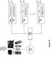
- FIG. 1Aillustrates a system for servicing user accounts according to an embodiment of the present invention.
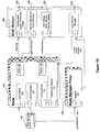
- FIG. 1Billustrates a component diagram of the system of FIG. 1A according to an embodiment of the present invention.
- FIG. 2Aillustrates an implementation of the device manager of FIG. 1B according to an embodiment of the present invention.
- FIG. 2Billustrates an implementation of the content router of FIG. 1B according to an embodiment of the present invention.
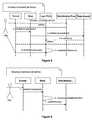
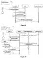
- FIG. 3illustrates a sequence diagram for registering a blade according to an embodiment of the present invention.
- FIG. 4illustrates a sequence diagram for revoking a blade according to an embodiment of the present invention.
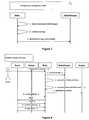
- FIG. 5illustrates a sequence diagram for creating a user according to an embodiment of the present invention.
- FIG. 6illustrates a sequence diagram for removing a user according to an embodiment of the present invention.
- FIG. 7illustrates a sequence diagram for changing user configuration data according to an embodiment of the present invention.
- FIG. 8illustrates a sequence diagram for disaster recovery of a user according to an embodiment of the present invention.
- FIG. 9illustrates a sequence diagram for changing global data according to an embodiment of the present invention.
- FIG. 10illustrates a sequence diagram for repartitioning a user according to an embodiment of the present invention.
- FIG. 11illustrates a sequence diagram for disaster recovery of a blade according to an embodiment of the present invention.
- FIG. 12Aillustrates a method for inviting a user from a different blade to share data according to an embodiment of the present invention.
- FIG. 12Billustrates a method for accepting the invitation to share data of FIG. 12 a according to an embodiment of the present invention.
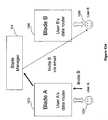
- FIG. 12Cillustrates connections between blade A and blade B for User A and User B to share data according to an embodiment of the present invention.
- FIG. 12Dillustrates a method for sharing data between two users on different blades using a pipe device according to an embodiment of the present invention.
- FIG. 13illustrates a sequence diagram for sharing data between users hosted by different blades according to an embodiment of the present invention.
- FIG. 14illustrates a prior art system for servicing user accounts.
- the present inventionenables servicing user accounts in scalable software blade architecture.
- the following descriptionsare presented to enable any person skilled in the art to make and use the invention. Descriptions of specific embodiments and applications are provided only as examples. Various modifications and combinations of the examples described herein will be readily apparent to those skilled in the art, and the general principles defined herein may be applied to other examples and applications without departing from the spirit and scope of the invention. Thus, the present invention is not intended to be limited to the examples described and shown, but is to be accorded the widest scope consistent with the principles and features disclosed herein.
- a procedure, computer-executed step, logic block, process, etc.is here conceived to be a self-consistent sequence of one or more steps or instructions leading to a desired result.
- the stepsare those utilizing physical manipulations of physical quantities. These quantities can take the form of electrical, magnetic, or radio signals capable of being stored, transferred, combined, compared, and otherwise manipulated in a computer system. These signals may be referred to at times as bits, values, elements, symbols, characters, terms, numbers, or the like.
- Each stepmay be performed by hardware, software, firmware, or combinations thereof.
- Some examples described hereinprovide systems and methods for providing an aggregated backend (e.g., comprising one or more server computers) that supports a user account (e.g., such as a Yahoo! email account or the like), where the aggregated backend includes data available on other backends of associated content nodes (e.g., other users accounts, exchanges, devices, etc.).
- a usermay have two or more email accounts, including various applications, such as email, contacts, calendar, and the like associated with each account.
- a first user account backendmay mirror data of a second user account, such that data of the second account is accessible through the first user backend.
- the aggregated datais principally organized as a connected dataset having separate substructures, e.g., folder or other data file grouping system, provided by different content nodes.
- a connected datasetis established with an aggregated backend for each application type, whereby aggregation of two or more substructures, e.g., folder or other data file grouping system, provided by other content nodes also associated with or linked to the connected dataset, is done. In this manner a user may access data stored by two or more backends through one content node associated with the aggregated backend.
- a connected-data serviceenables users to share and access their connected dataset with any device at any time from anywhere.
- Client devicesalso referred to as user devices
- Client devicesmay include cellular phones, wireless personal digital assistants, navigation devices, personal computers, game consoles, Internet terminals, and Kiosks.
- a connected datasetmay include emails, contacts, calendar, tasks, notes, pictures, documents, music, videos, bookmarks, and links.
- a connected-data serviceis implemented by one or more content router servers (CRS).
- CRScontent router servers
- a CRSmay be implemented by one or more computers/servers in different geographical locations. The CRS manages the connected dataset among the different computing devices on which a user may create or store data, including personal computers, mobile devices, servers, and web portals.
- a scalable software blade architectureincludes one or more blades implementing a corresponding CRS for servicing a predefined group of user accounts.
- Each CRSmay have different configurations or versions of hardware and software components.
- the scalable software blade architecturemay incrementally add new blades for servicing the new user accounts.
- FIG. 1Aillustrates a system for servicing user accounts according to an embodiment of the present invention.
- the systemincludes a switch 102 , a blade manager 104 , and one or more blades 106 , such as blade 1 to blade n.
- the switchis connected to the Internet 108 , though which a plurality of user devices 110 may access the system.
- the switchmay be one or more hardware instances that are used to route the Internet traffic to the blade servers.
- the switchdirects a user device to the blade that is responsible for managing the user's connected dataset according to the Internet Protocol (IP) address of the blade server or other information included in each request for determining the target blade server.
- IPInternet Protocol
- the blade manager 104includes a user partitioning manager 112 , and a central configuration manager 114 .
- Each blade in the systemfunctions as a CRS 116 with its corresponding relational database management system (RDBMS) of the database partition 118 .
- RDBMSrelational database management system
- Each bladeincludes software components and hardware components, and each blade serves a predefined group of user accounts.
- the software componentsinclude one or more versions of operating systems and software applications.
- the hardware componentsinclude one or more versions of hardware platforms and configurations. Interactions between the blade manager and the blades are described in association with FIG. 1B below.
- FIG. 1Billustrates a component diagram of the system of FIG. 1A according to an embodiment of the present invention.
- the blade manager 104managers the states and configurations of user accounts for the one or more blades 106 in the system. It includes a storage for configuration and global preferences profile 122 , a storage for device description and account groups 124 , a storage for user settings 126 , and a user partitioning manager 128 .
- the configuration and global preferences profile 122includes configuration information applicable to all blades in the system.
- the device descriptions and account groups 124includes information about user devices, such as device types (e.g. Symbian device) and software versions for the different device types.
- the user settings 126include information such as types of services, user filter settings, and data sharing settings.
- the blade manageris also responsible for assigning new user accounts to a specific blade according to a set of predetermined requirements, including repartition and disaster recovery requirements when a blade fails.
- the user partition manager 128balances the load of servicing user accounts among the blades.
- Each bladeimplements a CRS and includes a user web UI 130 , a device manager 132 , a content router 133 , a DataSource gateway 134 , a poller logic 136 , and a pusher logic 138 .
- the DataSource gateway 134includes components for accessing user accounts. For example, it may access IMAP, POP, Exchange, and SyncML accounts through web.de, GMX, or MSN.
- the systemfurther includes a blade manager proxy 140 for functioning as a front-end interface between the blade manager 104 and the user devices 110 via the Internet. It is used to shield the blade manager 104 against direct access from the Internet, and thus protects the blade manager from unauthorized accesses.
- the blade manager proxy 140includes re-direct logic 142 for directing a user device to a new blade in case the blade hosting the device has failed or in case the old blade has moved.
- FIG. 2Aillustrates an implementation of the device manager of FIG. 1B according to an embodiment of the present invention.
- the device manager 132includes a web front-end 202 , a device controller 204 , a device description storage 206 , and a set of protocol adapters 208 .
- the device managercommunicates and manages the user devices 110 through the protocol adapters 208 .
- the device managercommunicates with other portions of the content router server through a user management unit 212 and a smart content routing unit 214 .
- the user management unitis the adapter to the user management system of the Internet Service Provider (ISP), for example Yahoo. It interacts with the ISP's user management to obtain permissions for a user or to receive information concerning a user has been removed.
- ISPInternet Service Provider
- the device controller 204further includes a software management unit 216 , a service manager 218 , a settings change dispatcher 220 , and a device state storage 222 .
- the software management unit 216initiates and controls installations, updates, and de-installations of applications for the user devices.
- the service manager 218manages the types of services supported for the user devices.
- the service managerprovides information to the smart content routing unit 214 for transferring the connected-date-set among the user devices and the content router server.
- the setting change dispatcher 220provides changes in device settings from the device manager to the user devices.
- the device state storage 222stores the information about the operating states of the user devices.
- the device description storage 206stores type descriptions 224 , transcodings 226 , account templates 228 , and service descriptions 230 of the user devices 110 supported by the connected-data service.
- the device managerassociates user devices with different combinations of type descriptions, transcodings, account templates, and service descriptions such that each of the combinations may be tested and verified for a predefined group of user devices. As a result, different service lines containing corresponding device characteristics and services may be provided to different groups of users.
- the protocol adapters 208may include a provisioning unit 232 , a record exchange unit 234 , a setting exchange unit 236 , an application exchange unit 238 , a SyncML unit 240 , and other adaptor units 242 .
- the functional units of the device manager described abovei.e. logical blocks 202 - 244
- the interactions among the functional unitsare further described in U.S. application Ser. No. 11/182,663, entitled “System and Method for Provisioning a User Device,” to Markus Meyer et al., which is hereby incorporated by reference in its entirety.
- FIG. 2Billustrates an implementation of the content router of FIG. 1B according to an embodiment of the present invention.
- the content router 133includes store and forward logic 210 , a protocol adapter 208 , and protocol interface logic 260 including a device gateway 264 and a server gateway 266 .
- the device gateway 264 and a server gateway 266translate between protocols used by devices and servers and a common protocol, such as an XML-RPC protocol.
- the protocol adapter 208translates between the common protocol and commands 400 used to communicate with the store and forward logic 210 .
- Commands 400 sent between the store and forward logic 210 and the protocol adapter 208may be in a request-response scheme such as in a JavaTM platform including a Remote Method Invocation over Internet Inter-ORB Protocol (RMI-IIOP) technology interface.
- RMI-IIOPRemote Method Invocation over Internet Inter-ORB Protocol
- a Java RMI platformallows an object running on a Java enabled content node to invoke methods on an object running in a Java based store and forward logic 210 and vice versa.
- the content router 133may configure the device gateway 264 and/or the server gateway 266 with one or more of the routing parameters and/or one or more of the transformation parameters, such that the gateway may perform routing and transformations on commands of a content node.
- the device gateway 264is shown coupling the protocol adapter 208 to a mobile phone 310 - 1 running a SyncML protocol 910 - 1 and a JavaTM based client device 310 - 2 operating with a binary protocol 910 - 2 .
- the server gateway 266is shown coupling the protocol adapter 208 to a PIM server 320 - 1 , a photo server 320 - 2 , and an email server 320 - 3 with protocols 920 - 1 , 920 - 2 , and 920 - 3 , respectively.
- a common protocolsuch as XML-RPC
- XML-RPCallows applications running on disparate operating systems and in different environments to make remote procedure calls using HTTP as a transport layer and XML as an encoding scheme.
- the XML-RPC protocolallows complex data structures to be transmitted from an application running on the device gateway 264 , the server gateway 266 , an XML-RPC-enabled device, or an XML-RPC-enabled server to the protocol adapter 208 and the store and forward logic 210 .
- the protocol adapter 208 or the store and forward logic 210may process the received data structure and return a result to the application.
- Content nodes having the capability to communicate using the common protocolmay bypass the gateway and may communicate directly with the protocol adapter 208 .
- a Symbian device or a WinCE, Win 32 or home personal computer (PC) 310 - 3 running a client applicationmay communicate directly with the protocol adapter 208 , which avoids the device gateway 264 , since the PC 310 - 3 already employs the common protocol.
- a smart phone 310 - 4may also communicate using the common protocol avoid the device gateway 264 .
- user accountsmay use the common protocol thereby bypassing the server gateway 266 to communicate with the protocol adapter 208 .
- a Yahoo!® server 320 - 4uses the common protocol thereby avoiding the server gateway 266 .
- a content nodecommunicates with commands 400 directly (not shown), and thus may avoid using a protocol adapter 208 .
- the protocol adapter 208may treat messages 801 from device gateway 264 , messages 803 from a server gateway 266 , messages 810 - 3 , 810 - 4 from user devices 310 - 3 , 310 - 4 and messages 820 - 4 from user accounts 320 - 4 similarly, thereby simplifying the design and implementation of the protocol adapter 208 . Therefore, incoming messages in the common protocol are treated similarly regardless of input path to the protocol adapter 208 . As a result, the store and forward logic 210 may treat commands from each content node similarly.
- the content router 133may also include a notification signal (dotted line) sent from the store and forward logic 210 to a device and/or server gateway 264 , 266 as shown in FIG. 2B . If an outgoing command is waiting in the outgoing queue, the store and forward logic 210 may periodically send a notification signal (dotted lines) to the appropriate gateway 264 , 266 . A notification may be send from the store and forward logic 210 to the gateway 264 , 266 using telnet, HTTP, a custom API, or the like. The gateway 264 , 266 then may initiate a request for the outgoing command or commands 400 from the store and forward logic 210 . The gateway 264 , 266 may receive a response including the command from the outgoing queue.
- a notification signal(dotted line) sent from the store and forward logic 210 to a device and/or server gateway 264 , 266 as shown in FIG. 2B . If an outgoing command is waiting in the outgoing queue, the store and forward logic 210 may periodically send a notification signal
- the gatewayprepares an outgoing notification message containing the command. If the outgoing command is relatively small in size, the gateway 264 , 266 may include the command within the notification.
- the store and forward logic 210determines that a notification may be sent to a content node to inform the content node that the outgoing queue (within the store and forward logic 210 ) may contain an outgoing command.
- the store and forward logic 210generates a notification signal for a gateway 264 , 266 .
- the gateway 264 , 266receives a notification signal from the store and forward logic 210 .
- the notification signalmay indicate availability of an outgoing command in the outgoing queue for a content node.
- the gateway 264 , 266may request the outgoing command, for example, by a call to the protocol adapter 208 .
- the protocol adapter 208retrieves the command from the store and forward logic 210 , which provides it to the gateway 264 , 266 .
- the gateway 264 , 266receives the response containing the outgoing command.
- the gateway 264 , 266prepares an outgoing notification containing the outgoing command.
- the gateway 264 , 266may encode the outgoing command into a compact binary sequence.
- the gateway 264 , 266then sends the outgoing notification to the content node, which may be either a user device 310 such as a mobile phone or a user account 320 such as an email account.
- a device gateway 264may send the outgoing notification to a mobile phone by way of an SMS gateway.
- the gateway 264 , 266may send an acknowledgement of the outgoing notification to the store and forward logic 210 via the protocol adapter 208 .
- the functional units of the content router 133 described abovemay be implemented in software, hardware, or a combination of software and hardware. The interactions among the functional units of the content router are further described in U.S. application Ser. No. 11/182,287, entitled “Content Router,” to Torsten Schulz et al., which is hereby incorporated by reference in its entirety.
- each bladeimplements a CRS.
- One benefit of this approachis that it eliminates the need for synchronizing or accessing data through a very fast network from other machines as required by the prior art system shown in FIG. 14 .
- accessing a central pointsuch as the large central database of FIG. 14
- the scalable software blade architectureensures that a failure of the blade manager (central point) does not impact the service of the user accounts at each individual blade. Since the central point may not be up and running all the time, the method ensures that if this central point fails, the normal flow still works.
- configurations informationsuch as the connectivity of devices and accounts (which device is connected to which account and what filters are set), and filters are backed up.
- the systemis able to recover with that configuration data only. Therefore, the amount of backup data and number of backup calls per device are reduced.
- Content dataare not permanently stored in a blade.
- the bladeis able to recover from a server crash without that data.
- the userdoes not lose data, because user data is fetched and dispatched from the user devices and user accounts.
- Global datais hosted by the blade manager.
- a bladepolls the blade manager from time to time for changes to the configuration data, retrieves and stores the changes in a local cache on the blade. Exchanging user content data between blades is done through a store-and-forward mechanism as described above in association with FIG. 2B .
- FIG. 3illustrates a sequence diagram for registering a blade according to an embodiment of the present invention. It is desirable to simplify the steps to register or revoke a new blade in the deployment.
- the administratorcalls the function setBootstrapInfo to set the location of the blade manager and provides the external and internal address of the blade.
- the blade managerassigns the number of user accounts to be hosted by the blade. Note that in another embodiment, the administrator may be implemented as an automatic process.
- the administratorcalls the function register that allows the blade to register itself at the blade manager.
- step 3the blade calls the function registerBlade to register itself at the partition manager within the blade manager. Note that the blade manager, which is the first node in the deployment, needs to be known by all other blades. There is no special process registering or revoking it.
- the blade manager proxyalso registers itself at the blade manager.
- FIG. 4illustrates a sequence diagram for revoking a blade according to an embodiment of the present invention.
- the administratorcalls the function doNotAssignNewUsersToThisBlade and stops the blade manager from assigning new users to the blade to be revoked.
- the administratorcalls the function repartition Users to repartition the user accounts from the blade that is to be revoked.
- the blade managercalls the function moveUserFrom to inform the blades that should take over the users about moving user accounts from the blade. This procedure is further described below in association with repartitioning a user.
- the new bladecalls the function userMoved to inform the blade manager about the move.
- This informationis used by the administrator to determine that all users have been moved.
- step 5after the administrator determines that the user accounts for all users have been repartitioned, it calls the function revokeBlade to revoke the blade.
- step 6the administrator installs a new blade using the same IP address; this corresponds to a move command for the devices. The administrator may install other information that responds to the devices with a move command.
- step 6a device that tries to connect to the revoked blade is redirected to go through the blade manager proxy.
- the blade manager proxydirects the device to the new blade. If the device does not get a proper response, it waits for a predetermined period of time (for example an hour) before contacting the blade manager proxy for accessing the blade.
- FIG. 5illustrates a sequence diagram for creating a user according to an embodiment of the present invention.
- the userbrowses the CRS sign-in URL.
- the target of this URLis the blade manager proxy.
- the blade manager proxyredirects the URL to one of the blades.
- the userselects “register” and enters the information to enable the CRS on the blade through the enableConnectedLife function call.
- the enableConnectedLife callis delegated to the blade manager that performs the task of enabling the connected-data service. Not shown in this diagram is that the blade manager has a connection to the service provider's user management system that handles this activity.
- the blade managercalls the function createUser to the blade where the user should be created.
- the bladeneeds to be up and running (online) to perform this step. This ensures that the user already exists before the browser is redirected to that blade.
- the bladecalls the function createDefaultAccount to create a default user account.
- the browseraccesses the blade and displays the connected-data service welcome page. Note that step 6 may be performed before step 5 or vice versa.
- FIG. 6illustrates a sequence diagram for removing a user according to an embodiment of the present invention.
- the usercalls the function disableConnectedLife to disable the CRS.
- the bladecalls the function removeUserDatabaseEntries to remove the user. This process is performed offline, because un-installation of the devices needs to be completed first. After a specific period of time (for example two hours), the user may be removed nevertheless without un-installation of the devices.
- the bladecalls the function userRemoved to inform the blade manager that the user has been removed.
- FIG. 7illustrates a sequence diagram for changing user configuration data according to an embodiment of the present invention.
- the bladecalls the function determinesUserConfigChange to detect that user configuration data has changed. Note that this data is changed through user interaction, such as adding a new device, adding a new account, or adding a new address-book in an account. Under normal conditions, changes happen infrequently.
- a user configuration dataincludes a) connection information between account and devices; b) device and account attributes like name, password, and phone number; and c) user specific data such as location, language, and profile.
- the bladecalls the function scheduleBackup to schedule an offline (asynchronous) backup.
- step 3the blade calls the function storeUserConfigs to store the user configuration data in the blade manager as an XML document, which is a relatively small amount of data about the size of 3 to 5 kilobytes.
- the task of storing user configuration datamay be accomplished in one function call.
- FIG. 8illustrates a sequence diagram for disaster recovery of a user according to an embodiment of the present invention.
- the administratorcalls the function disasterRecoverUser at the blade where the user resides. This initiates the process of recreating the user account from the user configuration data.
- the user configuration datais stored in a backup, which may be updated every time the user configuration data changes.
- the bladecalls the function getUserConfig to retrieve the user configuration data from the blade manager.
- the bladecalls the function removeUserDatabaseEntries to remove the user's database entries.
- the bladecalls the function reconstructDevicesAndAccounts to reconstruct accounts and devices from the user configuration.
- step 5the blade calls the function getFilterShadowData to trigger the process of importing filter information for all accounts.
- the devicecalls the function exchangeData to exchange data. It gets back a special return code that indicates a repair is necessary.
- step 7the device calls the function repair to perform the repair. Note that steps 5 and 6 are different for SyncML and MMS devices. For SyncML, a slow sync is performed to import data from the backend. For MMS, no importation of content data from the backend is necessary, because only the newest mail is sent to the phone.
- step 8the device calls the function sendCheckSums to send a checksum. This is an optimization procedure to avoid software reinstallation and/or getting and putting all data contents again.
- step 9the device calls the function importData to import the PIM data again in response to the checksum and information indicating whether the data on the device is up-to-date.
- FIG. 9illustrates a sequence diagram for changing global data according to an embodiment of the present invention.
- the global datachanges on the CRMS first, where the CRMS is part of the blade manager.
- the bladesreceive this information with polling.
- the global datais exchanged as XML documents or as zip-packages through which documents and device binaries are assembled.
- the global datais required to be backward compatible.
- a set of new global dataneeds to be able to work with existing blades.
- the set of new global dataneeds to be proven stable before the set of old global data is removed. For example, if the SMTP server changes, the old global data still needs to be made available until all blades are updated to the set of new global data.
- step 1the administrator calls the function changeConfiguration to change a configuration value.
- step 2the administrator calls the function addDeviceDescription to add a device type description.
- step 3the CRMS reflects the changes. Each blade is responsible to determine what has changed by calling the function queryChanges. This call returns the information that has changed. In this example, the configuration and device descriptions have changed.
- step 4the blade calls the function getConfiguration to request the user configuration data.
- step 5the blade calls the function getAddedDescriptions to fetch the newest device descriptions.
- step 6the blade calls the function addChangesToPersistentCache to store the changed information and/or data in a persistent cache of the blade.
- step 7the blade calls the function setCurrentGlobalDataCheckMark to inform the partition manager about global data that is in the persistent cache. This information is used to determine when all blades perform the update of global data. For example, after all blades update to the new configuration version, where the new SMPP server is configured, then the old configuration can be removed from the system.
- FIG. 10illustrates a sequence diagram for repartitioning a user according to an embodiment of the present invention.
- This sequence diagramdescribes a process where a user account is moved from blade 1 to blade 2 .
- the administratorcalls the function repartition User to trigger the repartitioning process at a blade manager.
- the partition managercalls the function doUserRepartition to inform blade 2 to perform the task of repartitioning.
- blade 2calls the function disableAllDevicesAndAccounts to disable all external communication for the user on blade 1 .
- blade 2calls the function getUserConfig to get the user configuration from blade 1 .
- blade 2calls the function removeUserDatabaseEntries to direct blade 1 to remove all user related data. After this call, blade 1 may not update the user configuration due to the possibility of creating potential race conditions.
- blade 2calls the function reconstructDevicesAndAccounts to re-create user accounts and devices.
- blade 2calls the function userRepartitioned to inform the blade manager that the user has been moved successfully. After this call, blade 2 updates the user configuration data.
- the devicecalls the function exchangeData to access blade 1 for the exchanged data. It still does not know about the move.
- blade 1Since blade 1 no longer has information about the user (and the user's devices and accounts) after the move, it returns an error indicating that this device is unknown.
- the error returned in step 8prompts the device to query the blade manager proxy for the new location of the device by calling the function getNewLocation.
- the devicecalls the function exchangeData to access the new location on blade 2 and to exchange data.
- Blade 2responds with a code that the device should initiate a repair process.
- the devicecalls the function repair to initiate the repair process. In addition, it calls functions sendCheckSum and importData similar to the situation of disaster recovery of a user as described in FIG. 8 .
- FIG. 11illustrates a sequence diagram for disaster recovery of a blade according to an embodiment of the present invention.
- This sequence diagramdescribes the scenario when a blade has crashed and the data on the disk is lost.
- a blade monitoring tooldetermines that the blade has crashed and informs the administrator.
- the administratorcalls the function stopAssigningUsersToCrashedBlade to stop assigning users to the crashed blade.
- the administratorcalls the function assign UsersToOtherBlades to direct the blade manager to move the users to other blades in the system.
- the blade managercalls the function createUsers to create new users on other blades. Note that by distributing the users to multiple blades, the peak load during disaster recovery is reduced.
- steps 5 to 12are performed for moving a user account and its associated user devices.
- the bladescall the function getUserConfig to fetch the user configuration.
- the bladescall the function createUserDatabase to create database entries.
- the bladescall the function reconstructDevicesAndAccounts to create the devices and accounts using the user configuration information.
- the administratorprovides the IP address at a repartition responder that directs the device to move. Steps 9 - 12 describe the process for moving the devices. These steps are similar to the user repartition case described above.
- FIGS. 12A-12Ddescribe a method for sharing data between two users on different blades according to embodiments of the present invention.
- FIG. 12Aillustrates a method for inviting a user from a different blade to share data according to an embodiment of the present invention.
- blade A 1202implements the CRS of user A 1204 and functions as the data router for user A.
- blade B 1206implements the CRS of user B 1208 and functions as the data router for user B.
- a blademanages a user's data.
- blade Amanages the data of user A
- blade Bmanages the data of user B.
- Both blade A and blade Bare managed by the blade manager 104 as described above.
- blade ATo invite user B to share data, user A creates an invite B message and sends the message to blade A. Blade A passes the invitation to the blade manager. Next, the blade manager determines whether user B exists and has access to the connected-data service. If user B does not exist or has no access to the connected-data service, a notification is sent to user A regarding the status of the invitation. In the alternative, if user B does exist and has access to the connected-data service, the blade manager sends the invitation message to user B (shown as the dotted line). Note that the invitation message may be presented in various formats such as electronic mail, instant messenger, or hyperlink to a webpage. In another approach, the blade manager may delegate the task of sending the invitation message to blade B.
- FIG. 12Billustrates a method for accepting the invitation to share data of FIG. 12A according to an embodiment of the present invention.
- user B 1208sends an acceptance (shown as dotted line) to share data with user A 1204 through the blade manager 104 .
- the blade managercreates connections between blade A 1202 and blade B 1206 for user A and user B to share data.
- FIG. 12Cillustrates connections between blade A and blade B for user A and user B to share data according to an embodiment of the present invention.
- a dataset AB to be shared between user A and user Bis defined by user A.
- the corresponding access restrictions for the dataset ABare defined by user A for user B.
- the dataset AB and its corresponding access restrictionsare forwarded from blade A to blade B. Note that the access restrictions stored on blade B is an executable version of the access restrictions on blade A.
- FIG. 12Dillustrates a method for sharing data between two users on different blades using a pipe device according to an embodiment of the present invention.
- blade A 1202is the CRS for user A 1204 , which may have one or more user devices such as A 1 1203 and A 2 1205 .
- Blade B 1206is the CRS for user B 1208 , which may also have one or more user devices such as B 1 1207 and B 2 1209 .
- a virtual pipe device 1210(shown as dotted line) is created between blade A and blade B for propagating changes of shared data between user A and user B. In particular, the pipe device propagates dataset AB and subsequent changes to dataset AB made by user A from blade A to blade B.
- the pipe devicepropagates access restrictions of dataset AB and subsequent changes to the access restrictions of dataset AB made by user A from blade A to blade B.
- the pipe deviceacts as a proxy of the first user from the perspective of the second blade, and acts as a proxy of the second user from the perspective of the first blade.
- the pipe devicereceives changes to dataset AB made by user B, and checks for access restrictions given to user B with respect to the dataset AB. If user B is not authorized to modify the dataset AB, no change will be made to the dataset AB. In the alternative, if user B is authorized to modify the dataset AB, then the dataset AB is modified by user B.
- the changes to dataset ABare propagated by the pipe device from blade B to blade A. Therefore by using the pipe device, user B can access the dataset AB on blade B without accessing blade A, and access restrictions for user B to the dataset AB are enforced without accessing blade A.
- FIG. 13illustrates a sequence diagram for sharing data between users hosted by different blades according to an embodiment of the present invention.
- user Acalls the function publishAddressBook on blade A to publish his address book (an example of content data), to user B.
- blade Acalls the function storePublishState to store the publish state. An inventory is kept on who published to whom. This call also triggers an asynchronous backup to the CRMS (not shown in the diagram).
- step 3blade A sends out an invitation to the mail server.
- user Bcalls the function readMail to get and read the mail.
- user Bselects the URL provided in the mail.
- the URLrefers to the partition manager, which is a part of the blade manager.
- the partition managerdetects the user's blade B and redirects the user to blade B.
- the browserrequests the page to show the invitation.
- blade Bcalls the function getUserBlade to inquire the partition manager about the destination of the information. In the invitation request, the publisher's unique name is included.
- blade Bcalls the function getInvitationInfo to get from blade A the information about the invitation. This is a synchronous request, which requires both blades and the partition manager be up and running.
- user Baccepts the invitation and subscribes to the address book.
- the browsercalls the function subscribe to send the subscription request to blade B.
- blade Bcalls the function storeSubscribeState to store the subscription state. This causes an asynchronous backup to the CRMS (not shown in the diagram).
- blade Bcalls the function establishPublishAndSubscribeState to establish a connection between blade B and blade A. This includes the store and forward mechanism used to access external devices. Also, a notification channel from blade A to blade B is established to inform the changes of the published data.
- the inventioncan be implemented in any suitable form including hardware, software, firmware or any combination of these.
- the inventionmay be implemented in a computer readable storage medium storing computer programs for execution by one or more computer systems having at least a processing unit, a user interface, and a memory.
- the inventionmay optionally be implemented partly as computer software running on one or more data processors and/or digital signal processors.
- the elements and components of an embodiment of the inventionmay be physically, functionally and logically implemented in any suitable way. Indeed the functionality may be implemented in a single unit, in a plurality of units or as part of other functional units. As such, the invention may be implemented in a single unit or may be physically and functionally distributed between different units and processors.
Landscapes
- Engineering & Computer Science (AREA)
- Computer Networks & Wireless Communication (AREA)
- Signal Processing (AREA)
- Data Exchanges In Wide-Area Networks (AREA)
- Information Transfer Between Computers (AREA)
Abstract
Description
Claims (36)
Priority Applications (1)
| Application Number | Priority Date | Filing Date | Title |
|---|---|---|---|
| US11/262,052US7873696B2 (en) | 2005-10-28 | 2005-10-28 | Scalable software blade architecture |
Applications Claiming Priority (1)
| Application Number | Priority Date | Filing Date | Title |
|---|---|---|---|
| US11/262,052US7873696B2 (en) | 2005-10-28 | 2005-10-28 | Scalable software blade architecture |
Publications (2)
| Publication Number | Publication Date |
|---|---|
| US20070100975A1 US20070100975A1 (en) | 2007-05-03 |
| US7873696B2true US7873696B2 (en) | 2011-01-18 |
Family
ID=37997893
Family Applications (1)
| Application Number | Title | Priority Date | Filing Date |
|---|---|---|---|
| US11/262,052Expired - Fee RelatedUS7873696B2 (en) | 2005-10-28 | 2005-10-28 | Scalable software blade architecture |
Country Status (1)
| Country | Link |
|---|---|
| US (1) | US7873696B2 (en) |
Cited By (3)
| Publication number | Priority date | Publication date | Assignee | Title |
|---|---|---|---|---|
| US20080253403A1 (en)* | 2007-04-10 | 2008-10-16 | Apertio Limited | Nomadic subscriber data system |
| US20080256020A1 (en)* | 2007-04-10 | 2008-10-16 | Apertio Limited | Variant entries in network data repositories |
| US9112873B2 (en) | 2007-04-10 | 2015-08-18 | Apertio Limited | Alias hiding in network data repositories |
Families Citing this family (16)
| Publication number | Priority date | Publication date | Assignee | Title |
|---|---|---|---|---|
| US8112549B2 (en) | 2005-07-14 | 2012-02-07 | Yahoo! Inc. | Alert mechanism for notifying multiple user devices sharing a connected-data-set |
| US7623515B2 (en)* | 2005-07-14 | 2009-11-24 | Yahoo! Inc. | Content router notification |
| US20070016636A1 (en)* | 2005-07-14 | 2007-01-18 | Yahoo! Inc. | Methods and systems for data transfer and notification mechanisms |
| US7631045B2 (en) | 2005-07-14 | 2009-12-08 | Yahoo! Inc. | Content router asynchronous exchange |
| US7788352B2 (en)* | 2005-07-14 | 2010-08-31 | Yahoo! Inc. | System and method for servicing a user device |
| US20070016632A1 (en)* | 2005-07-14 | 2007-01-18 | Yahoo! Inc. | System and method for synchronizing between a user device and a server in a communication network |
| US8417782B2 (en) | 2005-07-14 | 2013-04-09 | Yahoo! Inc. | Universal calendar event handling |
| US20070014277A1 (en)* | 2005-07-14 | 2007-01-18 | Yahoo! Inc. | Content router repository |
| US20070014307A1 (en)* | 2005-07-14 | 2007-01-18 | Yahoo! Inc. | Content router forwarding |
| US7849199B2 (en)* | 2005-07-14 | 2010-12-07 | Yahoo ! Inc. | Content router |
| US20070100856A1 (en)* | 2005-10-21 | 2007-05-03 | Yahoo! Inc. | Account consolidation |
| US7779157B2 (en) | 2005-10-28 | 2010-08-17 | Yahoo! Inc. | Recovering a blade in scalable software blade architecture |
| US7870288B2 (en)* | 2005-10-28 | 2011-01-11 | Yahoo! Inc. | Sharing data in scalable software blade architecture |
| US8024290B2 (en)* | 2005-11-14 | 2011-09-20 | Yahoo! Inc. | Data synchronization and device handling |
| US8065680B2 (en) | 2005-11-15 | 2011-11-22 | Yahoo! Inc. | Data gateway for jobs management based on a persistent job table and a server table |
| US20080034008A1 (en)* | 2006-08-03 | 2008-02-07 | Yahoo! Inc. | User side database |
Citations (105)
| Publication number | Priority date | Publication date | Assignee | Title |
|---|---|---|---|---|
| US5457478A (en) | 1992-10-26 | 1995-10-10 | Firstperson, Inc. | Control device |
| US5475813A (en) | 1994-07-18 | 1995-12-12 | International Business Machines Corporation | Routing transactions in the presence of failing servers |
| US5625757A (en) | 1993-12-24 | 1997-04-29 | Hitachi, Ltd. | Printing system |
| US5671354A (en) | 1995-02-28 | 1997-09-23 | Hitachi, Ltd. | Method of assisting server access by use of user authentication information held in one of servers and a method of assisting management user account for use of servers |
| US5684952A (en) | 1994-07-25 | 1997-11-04 | Apple Computer, Inc. | Supervisory control system for networked multimedia workstations that provides reconfiguration of workstations by remotely updating the operating system |
| US5742905A (en)* | 1994-09-19 | 1998-04-21 | Bell Communications Research, Inc. | Personal communications internetworking |
| US5764908A (en) | 1996-07-12 | 1998-06-09 | Sofmap Future Design, Inc. | Network system containing program modules residing in different computers and executing commands without return results to calling modules |
| US5814798A (en) | 1994-12-26 | 1998-09-29 | Motorola, Inc. | Method and apparatus for personal attribute selection and management using prediction |
| US5852724A (en) | 1996-06-18 | 1998-12-22 | Veritas Software Corp. | System and method for "N" primary servers to fail over to "1" secondary server |
| US5867665A (en)* | 1997-03-24 | 1999-02-02 | Pfn, Inc | Domain communications server |
| US5913032A (en) | 1994-04-04 | 1999-06-15 | Inprise Corporation | System and methods for automatically distributing a particular shared data object through electronic mail |
| US5937388A (en)* | 1996-12-05 | 1999-08-10 | Hewlett-Packard Company | System and method for performing scalable distribution of process flow activities in a distributed workflow management system |
| US5956719A (en) | 1996-03-29 | 1999-09-21 | Fujitsu Limited | Synchronization method applied to databases in network management system |
| US6065054A (en)* | 1997-07-07 | 2000-05-16 | International Business Machines Corporation | Managing a dynamically-created user account in a client following authentication from a non-native server domain |
| US6069896A (en) | 1996-10-15 | 2000-05-30 | Motorola, Inc. | Capability addressable network and method therefor |
| US6108779A (en) | 1998-07-17 | 2000-08-22 | International Business Machines Corporation | Server and computer network that permit a client to be easily introduced into the computer network |
| US6141690A (en) | 1997-07-31 | 2000-10-31 | Hewlett-Packard Company | Computer network address mapping |
| US6144999A (en) | 1998-05-29 | 2000-11-07 | Sun Microsystems, Incorporated | Method and apparatus for file system disaster recovery |
| US6144959A (en)* | 1997-08-18 | 2000-11-07 | Novell, Inc. | System and method for managing user accounts in a communication network |
| US6157944A (en) | 1997-05-14 | 2000-12-05 | Citrix Systems, Inc. | System and method for replicating a client/server data exchange to additional client notes connecting to the server |
| US6170065B1 (en) | 1997-11-14 | 2001-01-02 | E-Parcel, Llc | Automatic system for dynamic diagnosis and repair of computer configurations |
| US6233612B1 (en)* | 1998-08-31 | 2001-05-15 | International Business Machines Corporation | Dynamic network protocol management information base options |
| US6256676B1 (en) | 1998-11-18 | 2001-07-03 | Saga Software, Inc. | Agent-adapter architecture for use in enterprise application integration systems |
| US6269406B1 (en)* | 1998-10-19 | 2001-07-31 | International Business Machines Corporation | User group synchronization to manage capabilities in heterogeneous networks |
| US6308201B1 (en) | 1999-04-08 | 2001-10-23 | Palm, Inc. | System and method for sharing data among a plurality of personal digital assistants |
| US6311205B1 (en)* | 1998-10-19 | 2001-10-30 | International Business Machines Corporation | Persistent user groups on servers managed by central servers |
| US20010049717A1 (en) | 2000-05-08 | 2001-12-06 | Freeman Thomas D. | Method and apparatus for communicating among a network of servers |
| US6341316B1 (en)* | 1999-09-10 | 2002-01-22 | Avantgo, Inc. | System, method, and computer program product for synchronizing content between a server and a client based on state information |
| US20020124114A1 (en) | 2001-03-05 | 2002-09-05 | Bottom David A. | Modular server architecture with ethernet routed across a backplane utilizing an integrated ethernet switch module |
| US6489954B1 (en) | 1998-10-13 | 2002-12-03 | Prophet Financial Systems, Inc. | System and method for permitting a software routine having restricted local access to utilize remote resources to generate locally usable data structure |
| US6496858B1 (en) | 1997-07-14 | 2002-12-17 | Tut Systems, Inc. | Remote reconfiguration of a secure network interface |
| US20020194295A1 (en)* | 2001-06-15 | 2002-12-19 | Groupe 2Mb Inc. | Scalable data-sharing architecture |
| US20030028817A1 (en) | 2001-08-06 | 2003-02-06 | Shigeru Suzuyama | Method and device for notifying server failure recovery |
| US6530083B1 (en) | 1998-06-19 | 2003-03-04 | Gateway, Inc | System for personalized settings |
| US6543004B1 (en) | 1999-07-29 | 2003-04-01 | Hewlett-Packard Development Company, L.P. | Method and apparatus for archiving and restoring data |
| US20030097487A1 (en) | 2001-11-20 | 2003-05-22 | Rietze Paul D. | Common boot environment for a modular server system |
| US6571354B1 (en) | 1999-12-15 | 2003-05-27 | Dell Products, L.P. | Method and apparatus for storage unit replacement according to array priority |
| US20030101190A1 (en) | 2001-03-14 | 2003-05-29 | Microsoft Corporation | Schema-based notification service |
| US20030135555A1 (en)* | 1997-06-16 | 2003-07-17 | Digital Equipment Corporation | Web-Based Electronic Mail Server Apparatus and Method Using Full Text and Label Indexing |
| US20030172139A1 (en) | 2002-03-11 | 2003-09-11 | Venkatachary Srinivasan | System and method for delivering data in a network |
| US20030172175A1 (en) | 2002-03-11 | 2003-09-11 | Mccormack Jonathan I. | System for standardizing updates of data on a plurality of electronic devices |
| US20030182327A1 (en) | 2002-03-20 | 2003-09-25 | Srinivasan Ramanujam | Synchronizing data shared between two devices independent of any other devices that may also share the data |
| US20030212684A1 (en) | 2002-03-11 | 2003-11-13 | Markus Meyer | System and method for adapting preferences based on device location or network topology |
| US20030233541A1 (en)* | 2002-06-14 | 2003-12-18 | Stephan Fowler | System and method for network operation |
| US20040003132A1 (en) | 2000-12-06 | 2004-01-01 | Biosentients, Inc. | Data pool architecture, system, and method for intelligent object data in heterogeneous data environments |
| US20040024831A1 (en) | 2002-06-28 | 2004-02-05 | Shih-Yun Yang | Blade server management system |
| US20040054780A1 (en)* | 2002-09-16 | 2004-03-18 | Hewlett-Packard Company | Dynamic adaptive server provisioning for blade architectures |
| US20040088414A1 (en) | 2002-11-06 | 2004-05-06 | Flynn Thomas J. | Reallocation of computing resources |
| US6748570B1 (en) | 1999-08-03 | 2004-06-08 | International Business Machines Corporation | Sending a view event, and a request event having a class name and a method name |
| US6751661B1 (en) | 2000-06-22 | 2004-06-15 | Applied Systems Intelligence, Inc. | Method and system for providing intelligent network management |
| US20040143836A1 (en) | 2003-01-21 | 2004-07-22 | Mccormack Jonathan Ian | System and method for sharing objects among two or more electronic devices |
| US6769124B1 (en) | 1998-07-22 | 2004-07-27 | Cisco Technology, Inc. | Persistent storage of information objects |
| US6813770B1 (en) | 2000-04-21 | 2004-11-02 | Sun Microsystems, Inc. | Abstract syntax notation to interface definition language converter framework for network management |
| US20040254829A1 (en) | 2003-05-13 | 2004-12-16 | Tripp Jeffrey William | Wireless access data sharing system |
| US20050015531A1 (en)* | 2003-05-29 | 2005-01-20 | Keizo Yabuta | Server system |
| US20050015430A1 (en) | 2003-06-25 | 2005-01-20 | Rothman Michael A. | OS agnostic resource sharing across multiple computing platforms |
| US6857123B1 (en) | 1998-12-18 | 2005-02-15 | International Business Machines Corporation | Method and apparatus for a Meta Data Service in a data processing system |
| US6865157B1 (en) | 2000-05-26 | 2005-03-08 | Emc Corporation | Fault tolerant shared system resource with communications passthrough providing high availability communications |
| US6868444B1 (en) | 2000-05-05 | 2005-03-15 | Interland, Inc. | Server configuration management and tracking |
| US20050060432A1 (en) | 2002-09-16 | 2005-03-17 | Husain Syed Mohammad Amir | Distributed computing infrastructure including small peer-to-peer applications |
| US20050080891A1 (en) | 2003-08-28 | 2005-04-14 | Cauthron David M. | Maintenance unit architecture for a scalable internet engine |
| US20050097360A1 (en) | 2003-10-31 | 2005-05-05 | International Business Machines Corporation | Secure switching for downloading network boots |
| US6931519B1 (en) | 2000-08-25 | 2005-08-16 | Sun Microsystems, Inc. | Method and apparatus for reliable booting device |
| US6931454B2 (en) | 2000-12-29 | 2005-08-16 | Intel Corporation | Method and apparatus for adaptive synchronization of network devices |
| US20050182838A1 (en)* | 2000-11-10 | 2005-08-18 | Galactic Computing Corporation Bvi/Ibc | Method and system for providing dynamic hosted service management across disparate accounts/sites |
| US20050182851A1 (en) | 2004-02-12 | 2005-08-18 | International Business Machines Corp. | Method and system to recover a failed flash of a blade service processor in a server chassis |
| US6944662B2 (en) | 2000-08-04 | 2005-09-13 | Vinestone Corporation | System and methods providing automatic distributed data retrieval, analysis and reporting services |
| US6965929B2 (en) | 2001-06-29 | 2005-11-15 | Intel Corporation | Configuring a network device |
| US6968345B1 (en) | 2002-02-27 | 2005-11-22 | Network Appliance, Inc. | Technique to enable support for symbolic link access by windows clients |
| US20050273645A1 (en) | 2004-05-07 | 2005-12-08 | International Business Machines Corporation | Recovery from fallures in a computing environment |
| US7020662B2 (en) | 2001-05-29 | 2006-03-28 | Sun Microsystems, Inc. | Method and system for determining a directory entry's class of service based on the value of a specifier in the entry |
| US20060101064A1 (en)* | 2004-11-08 | 2006-05-11 | Sharpcast, Inc. | Method and apparatus for a file sharing and synchronization system |
| US7051087B1 (en) | 2000-06-05 | 2006-05-23 | Microsoft Corporation | System and method for automatic detection and configuration of network parameters |
| US7051088B2 (en) | 2001-05-14 | 2006-05-23 | Hewlett-Packard Development Company, L.P. | Systems and methods for providing off-line backup of a programmable device's configuration data to users of programmable devices at a service location |
| US7054955B2 (en) | 2001-06-27 | 2006-05-30 | Microsoft Corporation | System and method for recovering from a failed synchronization session |
| US7085961B2 (en) | 2002-11-25 | 2006-08-01 | Quanta Computer Inc. | Redundant management board blade server management system |
| US7085824B2 (en) | 2001-02-23 | 2006-08-01 | Power Measurement Ltd. | Systems for in the field configuration of intelligent electronic devices |
| US7085822B1 (en) | 2000-03-14 | 2006-08-01 | International Business Machines Corporation | Managing pervasive devices |
| US7089297B1 (en) | 2001-05-25 | 2006-08-08 | Oracle International Corporation | Mechanism for automatically configuring a network resource |
| US7089259B1 (en) | 2001-08-03 | 2006-08-08 | Mcafee, Inc. | System and method for providing a framework for network appliance management in a distributed computing environment |
| US7093006B2 (en) | 2001-07-31 | 2006-08-15 | Motorola, Inc. | Method of dynamically configuring access to services |
| US20060259511A1 (en) | 2005-05-13 | 2006-11-16 | Yahoo! Inc. | Media object organization across information management services |
| US7165104B2 (en)* | 2001-04-23 | 2007-01-16 | Microsoft Corporation | Method and apparatus for managing computing devices on a network |
| US20070016636A1 (en) | 2005-07-14 | 2007-01-18 | Yahoo! Inc. | Methods and systems for data transfer and notification mechanisms |
| US20070014243A1 (en) | 2005-07-14 | 2007-01-18 | Yahoo! Inc. | System and method for provisioning a user device |
| US20070014278A1 (en) | 2005-07-14 | 2007-01-18 | Yahoo! Inc. | Counter router core variants |
| US20070016632A1 (en) | 2005-07-14 | 2007-01-18 | Yahoo! Inc. | System and method for synchronizing between a user device and a server in a communication network |
| US20070016646A1 (en) | 2005-07-14 | 2007-01-18 | Yahoo! Inc. | Universal calendar event handling |
| US20070014277A1 (en) | 2005-07-14 | 2007-01-18 | Yahoo! Inc. | Content router repository |
| US20070016676A1 (en) | 2005-07-14 | 2007-01-18 | Yahoo! Inc. | System and method for servicing a user device |
| US20070014307A1 (en) | 2005-07-14 | 2007-01-18 | Yahoo! Inc. | Content router forwarding |
| US20070014300A1 (en) | 2005-07-14 | 2007-01-18 | Yahoo! Inc. | Content router notification |
| US20070014244A1 (en) | 2005-07-14 | 2007-01-18 | Yahoo! Inc. | Alert mechanism for notifying multiple user devices sharing a connected-data-set |
| US20070028293A1 (en) | 2005-07-14 | 2007-02-01 | Yahoo! Inc. | Content router asynchronous exchange |
| US20070038703A1 (en) | 2005-07-14 | 2007-02-15 | Yahoo! Inc. | Content router gateway |
| US7185066B2 (en)* | 2001-10-11 | 2007-02-27 | Raytheon Company | Secure data sharing system |
| US7194655B2 (en)* | 2003-06-12 | 2007-03-20 | International Business Machines Corporation | Method and system for autonomously rebuilding a failed server and a computer system utilizing the same |
| US7200590B2 (en) | 2001-08-15 | 2007-04-03 | Yahoo! Inc. | Data sharing |
| US20070101021A1 (en) | 2005-10-28 | 2007-05-03 | Yahoo! Inc. | Recovering a blade in scalable software blade architecture |
| US20070100856A1 (en) | 2005-10-21 | 2007-05-03 | Yahoo! Inc. | Account consolidation |
| US20070101022A1 (en) | 2005-10-28 | 2007-05-03 | Yahoo! Inc. | Sharing data in scalable software blade architecture |
| US20070112880A1 (en) | 2005-11-14 | 2007-05-17 | Lie Yang | Data synchronization and device handling |
| US7272849B2 (en) | 2001-04-20 | 2007-09-18 | Hewlett-Packard Development Company, L.P. | System and method for sharing data |
| US7349957B1 (en)* | 2001-03-01 | 2008-03-25 | Smith Micro Software, Inc. | Network management method and tool |
| US7539862B2 (en) | 2004-04-08 | 2009-05-26 | Ipass Inc. | Method and system for verifying and updating the configuration of an access device during authentication |
Family Cites Families (1)
| Publication number | Priority date | Publication date | Assignee | Title |
|---|---|---|---|---|
| JP3503884B2 (en)* | 2000-01-28 | 2004-03-08 | 花王株式会社 | Cosmetics |
- 2005
- 2005-10-28USUS11/262,052patent/US7873696B2/ennot_activeExpired - Fee Related
Patent Citations (110)
| Publication number | Priority date | Publication date | Assignee | Title |
|---|---|---|---|---|
| US5457478A (en) | 1992-10-26 | 1995-10-10 | Firstperson, Inc. | Control device |
| US5625757A (en) | 1993-12-24 | 1997-04-29 | Hitachi, Ltd. | Printing system |
| US5913032A (en) | 1994-04-04 | 1999-06-15 | Inprise Corporation | System and methods for automatically distributing a particular shared data object through electronic mail |
| US5475813A (en) | 1994-07-18 | 1995-12-12 | International Business Machines Corporation | Routing transactions in the presence of failing servers |
| US5684952A (en) | 1994-07-25 | 1997-11-04 | Apple Computer, Inc. | Supervisory control system for networked multimedia workstations that provides reconfiguration of workstations by remotely updating the operating system |
| US5742905A (en)* | 1994-09-19 | 1998-04-21 | Bell Communications Research, Inc. | Personal communications internetworking |
| US5814798A (en) | 1994-12-26 | 1998-09-29 | Motorola, Inc. | Method and apparatus for personal attribute selection and management using prediction |
| US5671354A (en) | 1995-02-28 | 1997-09-23 | Hitachi, Ltd. | Method of assisting server access by use of user authentication information held in one of servers and a method of assisting management user account for use of servers |
| US5956719A (en) | 1996-03-29 | 1999-09-21 | Fujitsu Limited | Synchronization method applied to databases in network management system |
| US5852724A (en) | 1996-06-18 | 1998-12-22 | Veritas Software Corp. | System and method for "N" primary servers to fail over to "1" secondary server |
| US5764908A (en) | 1996-07-12 | 1998-06-09 | Sofmap Future Design, Inc. | Network system containing program modules residing in different computers and executing commands without return results to calling modules |
| US6069896A (en) | 1996-10-15 | 2000-05-30 | Motorola, Inc. | Capability addressable network and method therefor |
| US5937388A (en)* | 1996-12-05 | 1999-08-10 | Hewlett-Packard Company | System and method for performing scalable distribution of process flow activities in a distributed workflow management system |
| US5867665A (en)* | 1997-03-24 | 1999-02-02 | Pfn, Inc | Domain communications server |
| US6157944A (en) | 1997-05-14 | 2000-12-05 | Citrix Systems, Inc. | System and method for replicating a client/server data exchange to additional client notes connecting to the server |
| US20030135555A1 (en)* | 1997-06-16 | 2003-07-17 | Digital Equipment Corporation | Web-Based Electronic Mail Server Apparatus and Method Using Full Text and Label Indexing |
| US6065054A (en)* | 1997-07-07 | 2000-05-16 | International Business Machines Corporation | Managing a dynamically-created user account in a client following authentication from a non-native server domain |
| US6496858B1 (en) | 1997-07-14 | 2002-12-17 | Tut Systems, Inc. | Remote reconfiguration of a secure network interface |
| US6141690A (en) | 1997-07-31 | 2000-10-31 | Hewlett-Packard Company | Computer network address mapping |
| US6144959A (en)* | 1997-08-18 | 2000-11-07 | Novell, Inc. | System and method for managing user accounts in a communication network |
| US6170065B1 (en) | 1997-11-14 | 2001-01-02 | E-Parcel, Llc | Automatic system for dynamic diagnosis and repair of computer configurations |
| US6144999A (en) | 1998-05-29 | 2000-11-07 | Sun Microsystems, Incorporated | Method and apparatus for file system disaster recovery |
| US6530083B1 (en) | 1998-06-19 | 2003-03-04 | Gateway, Inc | System for personalized settings |
| US6108779A (en) | 1998-07-17 | 2000-08-22 | International Business Machines Corporation | Server and computer network that permit a client to be easily introduced into the computer network |
| US6769124B1 (en) | 1998-07-22 | 2004-07-27 | Cisco Technology, Inc. | Persistent storage of information objects |
| US6233612B1 (en)* | 1998-08-31 | 2001-05-15 | International Business Machines Corporation | Dynamic network protocol management information base options |
| US6489954B1 (en) | 1998-10-13 | 2002-12-03 | Prophet Financial Systems, Inc. | System and method for permitting a software routine having restricted local access to utilize remote resources to generate locally usable data structure |
| US6269406B1 (en)* | 1998-10-19 | 2001-07-31 | International Business Machines Corporation | User group synchronization to manage capabilities in heterogeneous networks |
| US6311205B1 (en)* | 1998-10-19 | 2001-10-30 | International Business Machines Corporation | Persistent user groups on servers managed by central servers |
| US6256676B1 (en) | 1998-11-18 | 2001-07-03 | Saga Software, Inc. | Agent-adapter architecture for use in enterprise application integration systems |
| US6857123B1 (en) | 1998-12-18 | 2005-02-15 | International Business Machines Corporation | Method and apparatus for a Meta Data Service in a data processing system |
| US6308201B1 (en) | 1999-04-08 | 2001-10-23 | Palm, Inc. | System and method for sharing data among a plurality of personal digital assistants |
| US6543004B1 (en) | 1999-07-29 | 2003-04-01 | Hewlett-Packard Development Company, L.P. | Method and apparatus for archiving and restoring data |
| US6748570B1 (en) | 1999-08-03 | 2004-06-08 | International Business Machines Corporation | Sending a view event, and a request event having a class name and a method name |
| US6341316B1 (en)* | 1999-09-10 | 2002-01-22 | Avantgo, Inc. | System, method, and computer program product for synchronizing content between a server and a client based on state information |
| US7000032B2 (en) | 1999-09-10 | 2006-02-14 | Ianywhere Solutions, Inc. | System, method, and computer program product for syncing to mobile devices |
| US6571354B1 (en) | 1999-12-15 | 2003-05-27 | Dell Products, L.P. | Method and apparatus for storage unit replacement according to array priority |
| US7085822B1 (en) | 2000-03-14 | 2006-08-01 | International Business Machines Corporation | Managing pervasive devices |
| US6813770B1 (en) | 2000-04-21 | 2004-11-02 | Sun Microsystems, Inc. | Abstract syntax notation to interface definition language converter framework for network management |
| US6868444B1 (en) | 2000-05-05 | 2005-03-15 | Interland, Inc. | Server configuration management and tracking |
| US20010049717A1 (en) | 2000-05-08 | 2001-12-06 | Freeman Thomas D. | Method and apparatus for communicating among a network of servers |
| US6865157B1 (en) | 2000-05-26 | 2005-03-08 | Emc Corporation | Fault tolerant shared system resource with communications passthrough providing high availability communications |
| US7051087B1 (en) | 2000-06-05 | 2006-05-23 | Microsoft Corporation | System and method for automatic detection and configuration of network parameters |
| US6751661B1 (en) | 2000-06-22 | 2004-06-15 | Applied Systems Intelligence, Inc. | Method and system for providing intelligent network management |
| US6944662B2 (en) | 2000-08-04 | 2005-09-13 | Vinestone Corporation | System and methods providing automatic distributed data retrieval, analysis and reporting services |
| US6931519B1 (en) | 2000-08-25 | 2005-08-16 | Sun Microsystems, Inc. | Method and apparatus for reliable booting device |
| US20050182838A1 (en)* | 2000-11-10 | 2005-08-18 | Galactic Computing Corporation Bvi/Ibc | Method and system for providing dynamic hosted service management across disparate accounts/sites |
| US20040003132A1 (en) | 2000-12-06 | 2004-01-01 | Biosentients, Inc. | Data pool architecture, system, and method for intelligent object data in heterogeneous data environments |
| US6931454B2 (en) | 2000-12-29 | 2005-08-16 | Intel Corporation | Method and apparatus for adaptive synchronization of network devices |
| US7085824B2 (en) | 2001-02-23 | 2006-08-01 | Power Measurement Ltd. | Systems for in the field configuration of intelligent electronic devices |
| US7349957B1 (en)* | 2001-03-01 | 2008-03-25 | Smith Micro Software, Inc. | Network management method and tool |
| US20020124114A1 (en) | 2001-03-05 | 2002-09-05 | Bottom David A. | Modular server architecture with ethernet routed across a backplane utilizing an integrated ethernet switch module |
| US20030101190A1 (en) | 2001-03-14 | 2003-05-29 | Microsoft Corporation | Schema-based notification service |
| US7272849B2 (en) | 2001-04-20 | 2007-09-18 | Hewlett-Packard Development Company, L.P. | System and method for sharing data |
| US7165104B2 (en)* | 2001-04-23 | 2007-01-16 | Microsoft Corporation | Method and apparatus for managing computing devices on a network |
| US7051088B2 (en) | 2001-05-14 | 2006-05-23 | Hewlett-Packard Development Company, L.P. | Systems and methods for providing off-line backup of a programmable device's configuration data to users of programmable devices at a service location |
| US7089297B1 (en) | 2001-05-25 | 2006-08-08 | Oracle International Corporation | Mechanism for automatically configuring a network resource |
| US7020662B2 (en) | 2001-05-29 | 2006-03-28 | Sun Microsystems, Inc. | Method and system for determining a directory entry's class of service based on the value of a specifier in the entry |
| US20020194295A1 (en)* | 2001-06-15 | 2002-12-19 | Groupe 2Mb Inc. | Scalable data-sharing architecture |
| US7054955B2 (en) | 2001-06-27 | 2006-05-30 | Microsoft Corporation | System and method for recovering from a failed synchronization session |
| US6965929B2 (en) | 2001-06-29 | 2005-11-15 | Intel Corporation | Configuring a network device |
| US7093006B2 (en) | 2001-07-31 | 2006-08-15 | Motorola, Inc. | Method of dynamically configuring access to services |
| US7089259B1 (en) | 2001-08-03 | 2006-08-08 | Mcafee, Inc. | System and method for providing a framework for network appliance management in a distributed computing environment |
| US20030028817A1 (en) | 2001-08-06 | 2003-02-06 | Shigeru Suzuyama | Method and device for notifying server failure recovery |
| US7200590B2 (en) | 2001-08-15 | 2007-04-03 | Yahoo! Inc. | Data sharing |
| US7185066B2 (en)* | 2001-10-11 | 2007-02-27 | Raytheon Company | Secure data sharing system |
| US20030097487A1 (en) | 2001-11-20 | 2003-05-22 | Rietze Paul D. | Common boot environment for a modular server system |
| US6968345B1 (en) | 2002-02-27 | 2005-11-22 | Network Appliance, Inc. | Technique to enable support for symbolic link access by windows clients |
| US20030172139A1 (en) | 2002-03-11 | 2003-09-11 | Venkatachary Srinivasan | System and method for delivering data in a network |
| US20030172175A1 (en) | 2002-03-11 | 2003-09-11 | Mccormack Jonathan I. | System for standardizing updates of data on a plurality of electronic devices |
| US20030172138A1 (en) | 2002-03-11 | 2003-09-11 | Mccormack Jonathan I. | System and method for managing two or more electronic devices |
| US20030212684A1 (en) | 2002-03-11 | 2003-11-13 | Markus Meyer | System and method for adapting preferences based on device location or network topology |
| US7346616B2 (en)* | 2002-03-20 | 2008-03-18 | Extended System, Inc. | Synchronizing data shared between two devices independent of any other devices that may also share the data |
| US20030182327A1 (en) | 2002-03-20 | 2003-09-25 | Srinivasan Ramanujam | Synchronizing data shared between two devices independent of any other devices that may also share the data |
| US20030233541A1 (en)* | 2002-06-14 | 2003-12-18 | Stephan Fowler | System and method for network operation |
| US20040024831A1 (en) | 2002-06-28 | 2004-02-05 | Shih-Yun Yang | Blade server management system |
| US20040054780A1 (en)* | 2002-09-16 | 2004-03-18 | Hewlett-Packard Company | Dynamic adaptive server provisioning for blade architectures |
| US20050060432A1 (en) | 2002-09-16 | 2005-03-17 | Husain Syed Mohammad Amir | Distributed computing infrastructure including small peer-to-peer applications |
| US20040088414A1 (en) | 2002-11-06 | 2004-05-06 | Flynn Thomas J. | Reallocation of computing resources |
| US7085961B2 (en) | 2002-11-25 | 2006-08-01 | Quanta Computer Inc. | Redundant management board blade server management system |
| US20040143836A1 (en) | 2003-01-21 | 2004-07-22 | Mccormack Jonathan Ian | System and method for sharing objects among two or more electronic devices |
| US20040254829A1 (en) | 2003-05-13 | 2004-12-16 | Tripp Jeffrey William | Wireless access data sharing system |
| US20050015531A1 (en)* | 2003-05-29 | 2005-01-20 | Keizo Yabuta | Server system |
| US7194655B2 (en)* | 2003-06-12 | 2007-03-20 | International Business Machines Corporation | Method and system for autonomously rebuilding a failed server and a computer system utilizing the same |
| US20050015430A1 (en) | 2003-06-25 | 2005-01-20 | Rothman Michael A. | OS agnostic resource sharing across multiple computing platforms |
| US20050080891A1 (en) | 2003-08-28 | 2005-04-14 | Cauthron David M. | Maintenance unit architecture for a scalable internet engine |
| US20050097360A1 (en) | 2003-10-31 | 2005-05-05 | International Business Machines Corporation | Secure switching for downloading network boots |
| US20050182851A1 (en) | 2004-02-12 | 2005-08-18 | International Business Machines Corp. | Method and system to recover a failed flash of a blade service processor in a server chassis |
| US7539862B2 (en) | 2004-04-08 | 2009-05-26 | Ipass Inc. | Method and system for verifying and updating the configuration of an access device during authentication |
| US20050273645A1 (en) | 2004-05-07 | 2005-12-08 | International Business Machines Corporation | Recovery from fallures in a computing environment |
| US20060101064A1 (en)* | 2004-11-08 | 2006-05-11 | Sharpcast, Inc. | Method and apparatus for a file sharing and synchronization system |
| US20060259511A1 (en) | 2005-05-13 | 2006-11-16 | Yahoo! Inc. | Media object organization across information management services |
| US20070014243A1 (en) | 2005-07-14 | 2007-01-18 | Yahoo! Inc. | System and method for provisioning a user device |
| US20070014277A1 (en) | 2005-07-14 | 2007-01-18 | Yahoo! Inc. | Content router repository |
| US20070014303A1 (en) | 2005-07-14 | 2007-01-18 | Yahoo! Inc. | Content router |
| US20070014244A1 (en) | 2005-07-14 | 2007-01-18 | Yahoo! Inc. | Alert mechanism for notifying multiple user devices sharing a connected-data-set |
| US20070028000A1 (en) | 2005-07-14 | 2007-02-01 | Yahoo! Inc. | Content router processing |
| US20070028293A1 (en) | 2005-07-14 | 2007-02-01 | Yahoo! Inc. | Content router asynchronous exchange |
| US20070038703A1 (en) | 2005-07-14 | 2007-02-15 | Yahoo! Inc. | Content router gateway |
| US20070014307A1 (en) | 2005-07-14 | 2007-01-18 | Yahoo! Inc. | Content router forwarding |
| US20070016676A1 (en) | 2005-07-14 | 2007-01-18 | Yahoo! Inc. | System and method for servicing a user device |
| US20070014300A1 (en) | 2005-07-14 | 2007-01-18 | Yahoo! Inc. | Content router notification |
| US20070016636A1 (en) | 2005-07-14 | 2007-01-18 | Yahoo! Inc. | Methods and systems for data transfer and notification mechanisms |
| US20070014278A1 (en) | 2005-07-14 | 2007-01-18 | Yahoo! Inc. | Counter router core variants |
| US20070016632A1 (en) | 2005-07-14 | 2007-01-18 | Yahoo! Inc. | System and method for synchronizing between a user device and a server in a communication network |
| US20070016646A1 (en) | 2005-07-14 | 2007-01-18 | Yahoo! Inc. | Universal calendar event handling |
| US20070100856A1 (en) | 2005-10-21 | 2007-05-03 | Yahoo! Inc. | Account consolidation |
| US20070101022A1 (en) | 2005-10-28 | 2007-05-03 | Yahoo! Inc. | Sharing data in scalable software blade architecture |
| US20070101021A1 (en) | 2005-10-28 | 2007-05-03 | Yahoo! Inc. | Recovering a blade in scalable software blade architecture |
| US20070112880A1 (en) | 2005-11-14 | 2007-05-17 | Lie Yang | Data synchronization and device handling |
Non-Patent Citations (21)
| Title |
|---|
| Coulouris, G. et al. (1994). Distributed Systems: Concepts and Design. Second Edition, Addison-Wesley Publishing Company, pp. 222-233, 311-318. |
| Final Office Action mailed on Dec. 22, 2009, for U.S. Appl. No. 11/262,340, filed Oct. 28, 2005, fourteen pages. |
| Final Office Action mailed on Nov. 17, 2009, for U.S. Appl. No. 11/262,549, filed Oct. 28, 2005, fifteen pages. |
| Fitzgerald, A. (Mar. 2003). "Blade-Based Storage Subsystems," CompactPCI Systems, 4 Pages. |
| International Search Report mailed Jul. 11, 2003, for PCT Application No. PCT/US03/07180 filed Mar. 11, 2003, 1 page. |
| International Search Report mailed Jun. 23, 2003, for PCT Application No. PCT/US03/07179 filed Mar. 11, 2003, 1 page. |
| International Search Report mailed Oct. 1, 2003, for PCT Application No. PCT/US03/07182 filed Mar. 11, 2003, 2 pages. |
| International Search Report mailed Oct. 18, 2004, for PCT Application No. PCT/US04/02033 filed Jan. 21, 2004, 1 page. |
| International Search Report mailed Oct. 8, 2003, for PCT Application No. PCT/US03/07181 filed Mar. 11, 2003, 1 page. |
| Nease, L. et al. (Apr. 2002). "Blade Servers: Driving the Standard," CompactPCI Systems, 6 Pages. |
| Non-Final Office Action mailed on Jun. 15, 2009, for U.S. Appl. No. 11/262,549, filed Oct. 28, 2005, twelve pages. |
| Non-Final Office Action mailed on May 21, 2009, for U.S. Appl. No. 11/262,340, filed Oct. 28, 2005, twelve pages. |
| Non-Final Office Action mailed on Oct. 1, 2008, for U.S. Appl. No. 11/262,340, filed Oct. 28, 2005, fourteen pages. |
| Non-Final Office Action mailed on Sep. 24, 2008, for U.S. Appl. No. 11/262,549, filed Oct. 28, 2005, fourteen pages. |
| U.S. Appl. No. 11/182,287, filed Jul. 14, 2005 for Schulz et al. |
| U.S. Appl. No. 11/182,663, filed Jul. 14, 2005 for Meyer et al. |
| U.S. Appl. No. 11/262,052, filed Oct. 28, 2005 for Srinivasan et al. |
| U.S. Appl. No. 11/262,340, filed Oct. 28, 2005 for Meyer et al. |
| U.S. Appl. No. 11/265,549, filed Oct. 28, 2005 for Schulz et al. |
| U.S. Appl. No. 11/796,258, filed Apr. 27, 2007 for Yang et al. |
| Wu, S. (Apr. 2002). "Blade Server-The Booming Server Technology of the Year 2002," CompactPCI Systems, 5 pages. |
Cited By (6)
| Publication number | Priority date | Publication date | Assignee | Title |
|---|---|---|---|---|
| US20080253403A1 (en)* | 2007-04-10 | 2008-10-16 | Apertio Limited | Nomadic subscriber data system |
| US20080256020A1 (en)* | 2007-04-10 | 2008-10-16 | Apertio Limited | Variant entries in network data repositories |
| US8402147B2 (en) | 2007-04-10 | 2013-03-19 | Apertio Limited | Nomadic subscriber data system |
| US8782085B2 (en) | 2007-04-10 | 2014-07-15 | Apertio Limited | Variant entries in network data repositories |
| US8996572B2 (en) | 2007-04-10 | 2015-03-31 | Apertio Limited | Variant entries in network data repositories |
| US9112873B2 (en) | 2007-04-10 | 2015-08-18 | Apertio Limited | Alias hiding in network data repositories |
Also Published As
| Publication number | Publication date |
|---|---|
| US20070100975A1 (en) | 2007-05-03 |
Similar Documents
| Publication | Publication Date | Title |
|---|---|---|
| US7870288B2 (en) | Sharing data in scalable software blade architecture | |
| US7873696B2 (en) | Scalable software blade architecture | |
| US7779157B2 (en) | Recovering a blade in scalable software blade architecture | |
| US8554887B2 (en) | System and method for efficient transfer of applications and data during device swap | |
| CN112839111B (en) | System, method, and medium for customizable event-triggered computation at edge locations | |
| JP5727020B2 (en) | Cloud computing system and data synchronization method thereof | |
| US7987266B2 (en) | Failover in proxy server networks | |
| WO2018218257A2 (en) | A hierarchical computing network and methods thereof | |
| CN106663033B (en) | System and method for supporting a wraparound domain and proxy model and updating service information for cross-domain messaging in a transactional middleware machine environment | |
| US9390156B2 (en) | Distributed directory environment using clustered LDAP servers | |
| US20060259523A1 (en) | System and method of synchronization of internal data cache with wireless device application data repositories | |
| US20190028561A1 (en) | Method and System of Forming Local and/or Hierarchical Cloud Networks | |
| US20070112812A1 (en) | System and method for writing data to a directory | |
| US7334038B1 (en) | Broadband service control network | |
| EP1872256B1 (en) | System and method of waste management | |
| US8572201B2 (en) | System and method for providing a directory service network | |
| US8478898B2 (en) | System and method for routing directory service operations in a directory service network | |
| JPWO2009034994A1 (en) | Load distribution system, service processing server, load distribution method, and load distribution program | |
| JP5494710B2 (en) | Application execution system, application execution method and program for application execution system | |
| CN103164410A (en) | File storage and operation method, file storage and operation storage equipment and file storage and operation system | |
| US20190387075A1 (en) | Methods for exposing mainframe data as a web service and devices thereof | |
| JP2008186222A (en) | Application execution system, computer, application execution method and program for application execution system | |
| CN111488324A (en) | Distributed network file system based on message middleware and working method thereof | |
| US9037702B2 (en) | Facilitating message services using multi-role systems | |
| WO2007123580A2 (en) | System and method for routing directory service operations in a directory service network |
Legal Events
| Date | Code | Title | Description |
|---|---|---|---|
| AS | Assignment | Owner name:YAHOO! INC., CALIFORNIA Free format text:ASSIGNMENT OF ASSIGNORS INTEREST;ASSIGNORS:SRINIVASAN, VENKATACHARY;MEYER, MARKUS;BOERRIES, MARCO;AND OTHERS;SIGNING DATES FROM 20051208 TO 20051216;REEL/FRAME:017137/0623 Owner name:YAHOO! INC., CALIFORNIA Free format text:ASSIGNMENT OF ASSIGNORS INTEREST;ASSIGNORS:SRINIVASAN, VENKATACHARY;MEYER, MARKUS;BOERRIES, MARCO;AND OTHERS;REEL/FRAME:017137/0623;SIGNING DATES FROM 20051208 TO 20051216 | |
| STCF | Information on status: patent grant | Free format text:PATENTED CASE | |
| FPAY | Fee payment | Year of fee payment:4 | |
| AS | Assignment | Owner name:EXCALIBUR IP, LLC, CALIFORNIA Free format text:ASSIGNMENT OF ASSIGNORS INTEREST;ASSIGNOR:YAHOO! INC.;REEL/FRAME:038383/0466 Effective date:20160418 | |
| AS | Assignment | Owner name:YAHOO! INC., CALIFORNIA Free format text:ASSIGNMENT OF ASSIGNORS INTEREST;ASSIGNOR:EXCALIBUR IP, LLC;REEL/FRAME:038951/0295 Effective date:20160531 | |
| AS | Assignment | Owner name:EXCALIBUR IP, LLC, CALIFORNIA Free format text:ASSIGNMENT OF ASSIGNORS INTEREST;ASSIGNOR:YAHOO! INC.;REEL/FRAME:038950/0592 Effective date:20160531 | |
| MAFP | Maintenance fee payment | Free format text:PAYMENT OF MAINTENANCE FEE, 8TH YEAR, LARGE ENTITY (ORIGINAL EVENT CODE: M1552) Year of fee payment:8 | |
| AS | Assignment | Owner name:STARBOARD VALUE INTERMEDIATE FUND LP, AS COLLATERAL AGENT, NEW YORK Free format text:PATENT SECURITY AGREEMENT;ASSIGNORS:ACACIA RESEARCH GROUP LLC;AMERICAN VEHICULAR SCIENCES LLC;BONUTTI SKELETAL INNOVATIONS LLC;AND OTHERS;REEL/FRAME:052853/0153 Effective date:20200604 | |
| AS | Assignment | Owner name:R2 SOLUTIONS LLC, TEXAS Free format text:ASSIGNMENT OF ASSIGNORS INTEREST;ASSIGNOR:EXCALIBUR IP, LLC;REEL/FRAME:053459/0059 Effective date:20200428 | |
| AS | Assignment | Owner name:PARTHENON UNIFIED MEMORY ARCHITECTURE LLC, TEXAS Free format text:RELEASE OF SECURITY INTEREST IN PATENTS;ASSIGNOR:STARBOARD VALUE INTERMEDIATE FUND LP;REEL/FRAME:053654/0254 Effective date:20200630 Owner name:LIMESTONE MEMORY SYSTEMS LLC, CALIFORNIA Free format text:RELEASE OF SECURITY INTEREST IN PATENTS;ASSIGNOR:STARBOARD VALUE INTERMEDIATE FUND LP;REEL/FRAME:053654/0254 Effective date:20200630 Owner name:R2 SOLUTIONS LLC, TEXAS Free format text:RELEASE OF SECURITY INTEREST IN PATENTS;ASSIGNOR:STARBOARD VALUE INTERMEDIATE FUND LP;REEL/FRAME:053654/0254 Effective date:20200630 Owner name:SUPER INTERCONNECT TECHNOLOGIES LLC, TEXAS Free format text:RELEASE OF SECURITY INTEREST IN PATENTS;ASSIGNOR:STARBOARD VALUE INTERMEDIATE FUND LP;REEL/FRAME:053654/0254 Effective date:20200630 Owner name:SAINT LAWRENCE COMMUNICATIONS LLC, TEXAS Free format text:RELEASE OF SECURITY INTEREST IN PATENTS;ASSIGNOR:STARBOARD VALUE INTERMEDIATE FUND LP;REEL/FRAME:053654/0254 Effective date:20200630 Owner name:INNOVATIVE DISPLAY TECHNOLOGIES LLC, TEXAS Free format text:RELEASE OF SECURITY INTEREST IN PATENTS;ASSIGNOR:STARBOARD VALUE INTERMEDIATE FUND LP;REEL/FRAME:053654/0254 Effective date:20200630 Owner name:LIFEPORT SCIENCES LLC, TEXAS Free format text:RELEASE OF SECURITY INTEREST IN PATENTS;ASSIGNOR:STARBOARD VALUE INTERMEDIATE FUND LP;REEL/FRAME:053654/0254 Effective date:20200630 Owner name:MONARCH NETWORKING SOLUTIONS LLC, CALIFORNIA Free format text:RELEASE OF SECURITY INTEREST IN PATENTS;ASSIGNOR:STARBOARD VALUE INTERMEDIATE FUND LP;REEL/FRAME:053654/0254 Effective date:20200630 Owner name:AMERICAN VEHICULAR SCIENCES LLC, TEXAS Free format text:RELEASE OF SECURITY INTEREST IN PATENTS;ASSIGNOR:STARBOARD VALUE INTERMEDIATE FUND LP;REEL/FRAME:053654/0254 Effective date:20200630 Owner name:NEXUS DISPLAY TECHNOLOGIES LLC, TEXAS Free format text:RELEASE OF SECURITY INTEREST IN PATENTS;ASSIGNOR:STARBOARD VALUE INTERMEDIATE FUND LP;REEL/FRAME:053654/0254 Effective date:20200630 Owner name:UNIFICATION TECHNOLOGIES LLC, TEXAS Free format text:RELEASE OF SECURITY INTEREST IN PATENTS;ASSIGNOR:STARBOARD VALUE INTERMEDIATE FUND LP;REEL/FRAME:053654/0254 Effective date:20200630 Owner name:BONUTTI SKELETAL INNOVATIONS LLC, TEXAS Free format text:RELEASE OF SECURITY INTEREST IN PATENTS;ASSIGNOR:STARBOARD VALUE INTERMEDIATE FUND LP;REEL/FRAME:053654/0254 Effective date:20200630 Owner name:CELLULAR COMMUNICATIONS EQUIPMENT LLC, TEXAS Free format text:RELEASE OF SECURITY INTEREST IN PATENTS;ASSIGNOR:STARBOARD VALUE INTERMEDIATE FUND LP;REEL/FRAME:053654/0254 Effective date:20200630 Owner name:STINGRAY IP SOLUTIONS LLC, TEXAS Free format text:RELEASE OF SECURITY INTEREST IN PATENTS;ASSIGNOR:STARBOARD VALUE INTERMEDIATE FUND LP;REEL/FRAME:053654/0254 Effective date:20200630 Owner name:ACACIA RESEARCH GROUP LLC, NEW YORK Free format text:RELEASE OF SECURITY INTEREST IN PATENTS;ASSIGNOR:STARBOARD VALUE INTERMEDIATE FUND LP;REEL/FRAME:053654/0254 Effective date:20200630 Owner name:MOBILE ENHANCEMENT SOLUTIONS LLC, TEXAS Free format text:RELEASE OF SECURITY INTEREST IN PATENTS;ASSIGNOR:STARBOARD VALUE INTERMEDIATE FUND LP;REEL/FRAME:053654/0254 Effective date:20200630 Owner name:TELECONFERENCE SYSTEMS LLC, TEXAS Free format text:RELEASE OF SECURITY INTEREST IN PATENTS;ASSIGNOR:STARBOARD VALUE INTERMEDIATE FUND LP;REEL/FRAME:053654/0254 Effective date:20200630 | |
| AS | Assignment | Owner name:R2 SOLUTIONS LLC, TEXAS Free format text:CORRECTIVE ASSIGNMENT TO CORRECT THE ASSIGNEE NAME PREVIOUSLY RECORDED ON REEL 053654 FRAME 0254. ASSIGNOR(S) HEREBY CONFIRMS THE RELEASE OF SECURITY INTEREST GRANTED PURSUANT TO THE PATENT SECURITY AGREEMENT PREVIOUSLY RECORDED;ASSIGNOR:STARBOARD VALUE INTERMEDIATE FUND LP;REEL/FRAME:054981/0377 Effective date:20200630 | |
| AS | Assignment | Owner name:STARBOARD VALUE INTERMEDIATE FUND LP, AS COLLATERAL AGENT, NEW YORK Free format text:CORRECTIVE ASSIGNMENT TO CORRECT THE THE ASSIGNOR NAME PREVIOUSLY RECORDED AT REEL: 052853 FRAME: 0153. ASSIGNOR(S) HEREBY CONFIRMS THE ASSIGNMENT;ASSIGNOR:R2 SOLUTIONS LLC;REEL/FRAME:056832/0001 Effective date:20200604 | |
| FEPP | Fee payment procedure | Free format text:MAINTENANCE FEE REMINDER MAILED (ORIGINAL EVENT CODE: REM.); ENTITY STATUS OF PATENT OWNER: LARGE ENTITY | |
| LAPS | Lapse for failure to pay maintenance fees | Free format text:PATENT EXPIRED FOR FAILURE TO PAY MAINTENANCE FEES (ORIGINAL EVENT CODE: EXP.); ENTITY STATUS OF PATENT OWNER: LARGE ENTITY | |
| STCH | Information on status: patent discontinuation | Free format text:PATENT EXPIRED DUE TO NONPAYMENT OF MAINTENANCE FEES UNDER 37 CFR 1.362 | |
| FP | Lapsed due to failure to pay maintenance fee | Effective date:20230118 |