US7873406B2 - Spectroscope for recovering light from re-entrant zone of arterial wall - Google Patents
Spectroscope for recovering light from re-entrant zone of arterial wallDownload PDFInfo
- Publication number
- US7873406B2 US7873406B2US11/772,887US77288707AUS7873406B2US 7873406 B2US7873406 B2US 7873406B2US 77288707 AUS77288707 AUS 77288707AUS 7873406 B2US7873406 B2US 7873406B2
- Authority
- US
- United States
- Prior art keywords
- spectroscope
- optical
- view
- optical fiber
- field
- Prior art date
- Legal status (The legal status is an assumption and is not a legal conclusion. Google has not performed a legal analysis and makes no representation as to the accuracy of the status listed.)
- Expired - Lifetime, expires
Links
- 230000003287optical effectEffects0.000claimsabstractdescription78
- 239000013307optical fiberSubstances0.000claimsabstractdescription26
- 238000004891communicationMethods0.000claimsabstractdescription16
- 238000000034methodMethods0.000claimsdescription13
- 238000005286illuminationMethods0.000claimsdescription10
- 210000004204blood vesselAnatomy0.000claimsdescription8
- 238000004611spectroscopical analysisMethods0.000claimsdescription4
- 239000000835fiberSubstances0.000description82
- 239000000463materialSubstances0.000description7
- 239000008280bloodSubstances0.000description6
- 210000004369bloodAnatomy0.000description6
- 239000004033plasticSubstances0.000description6
- 229920003023plasticPolymers0.000description6
- 238000007493shaping processMethods0.000description6
- 238000000576coating methodMethods0.000description5
- 238000009826distributionMethods0.000description5
- 210000001367arteryAnatomy0.000description4
- 239000011248coating agentSubstances0.000description4
- 230000008901benefitEffects0.000description3
- 238000005253claddingMethods0.000description3
- 238000001746injection mouldingMethods0.000description3
- 229910052751metalInorganic materials0.000description3
- 239000002184metalSubstances0.000description3
- 230000004048modificationEffects0.000description3
- 238000012986modificationMethods0.000description3
- XECAHXYUAAWDEL-UHFFFAOYSA-Nacrylonitrile butadiene styreneChemical compoundC=CC=C.C=CC#N.C=CC1=CC=CC=C1XECAHXYUAAWDEL-UHFFFAOYSA-N0.000description2
- 239000004676acrylonitrile butadiene styreneSubstances0.000description2
- 229920000122acrylonitrile butadiene styrenePolymers0.000description2
- XAGFODPZIPBFFR-UHFFFAOYSA-NaluminiumChemical compound[Al]XAGFODPZIPBFFR-UHFFFAOYSA-N0.000description2
- PCHJSUWPFVWCPO-UHFFFAOYSA-NgoldChemical compound[Au]PCHJSUWPFVWCPO-UHFFFAOYSA-N0.000description2
- 229910052737goldInorganic materials0.000description2
- 239000010931goldSubstances0.000description2
- 238000004519manufacturing processMethods0.000description2
- 239000002245particleSubstances0.000description2
- 201000001320AtherosclerosisDiseases0.000description1
- 239000004977Liquid-crystal polymers (LCPs)Substances0.000description1
- 239000004677NylonSubstances0.000description1
- 239000004952PolyamideSubstances0.000description1
- 239000004695Polyether sulfoneSubstances0.000description1
- 239000004697PolyetherimideSubstances0.000description1
- 229920000491PolyphenylsulfonePolymers0.000description1
- XUIMIQQOPSSXEZ-UHFFFAOYSA-NSiliconChemical compound[Si]XUIMIQQOPSSXEZ-UHFFFAOYSA-N0.000description1
- BQCADISMDOOEFD-UHFFFAOYSA-NSilverChemical compound[Ag]BQCADISMDOOEFD-UHFFFAOYSA-N0.000description1
- 208000007536ThrombosisDiseases0.000description1
- 206010047163VasospasmDiseases0.000description1
- 230000001154acute effectEffects0.000description1
- 229910052782aluminiumInorganic materials0.000description1
- 239000000919ceramicSubstances0.000description1
- 210000004351coronary vesselAnatomy0.000description1
- 238000005530etchingMethods0.000description1
- 239000000945fillerSubstances0.000description1
- 239000011521glassSubstances0.000description1
- 238000007373indentationMethods0.000description1
- 208000028867ischemiaDiseases0.000description1
- 150000002632lipidsChemical class0.000description1
- 150000002739metalsChemical class0.000description1
- 238000005459micromachiningMethods0.000description1
- 208000010125myocardial infarctionDiseases0.000description1
- 230000001338necrotic effectEffects0.000description1
- 229920001778nylonPolymers0.000description1
- 230000000149penetrating effectEffects0.000description1
- 229920002647polyamidePolymers0.000description1
- 239000004417polycarbonateSubstances0.000description1
- 229920000515polycarbonatePolymers0.000description1
- 229920006393polyether sulfonePolymers0.000description1
- 229920001601polyetherimidePolymers0.000description1
- 230000000750progressive effectEffects0.000description1
- 230000001681protective effectEffects0.000description1
- 239000010453quartzSubstances0.000description1
- 229910052710siliconInorganic materials0.000description1
- 239000010703siliconSubstances0.000description1
- VYPSYNLAJGMNEJ-UHFFFAOYSA-Nsilicon dioxideInorganic materialsO=[Si]=OVYPSYNLAJGMNEJ-UHFFFAOYSA-N0.000description1
- 229910052709silverInorganic materials0.000description1
- 239000004332silverSubstances0.000description1
- 238000009987spinningMethods0.000description1
- 238000007740vapor depositionMethods0.000description1
- 208000019553vascular diseaseDiseases0.000description1
Images


Classifications
- A—HUMAN NECESSITIES
- A61—MEDICAL OR VETERINARY SCIENCE; HYGIENE
- A61B—DIAGNOSIS; SURGERY; IDENTIFICATION
- A61B5/00—Measuring for diagnostic purposes; Identification of persons
- A61B5/0059—Measuring for diagnostic purposes; Identification of persons using light, e.g. diagnosis by transillumination, diascopy, fluorescence
- A61B5/0062—Arrangements for scanning
- A—HUMAN NECESSITIES
- A61—MEDICAL OR VETERINARY SCIENCE; HYGIENE
- A61B—DIAGNOSIS; SURGERY; IDENTIFICATION
- A61B5/00—Measuring for diagnostic purposes; Identification of persons
- A61B5/0059—Measuring for diagnostic purposes; Identification of persons using light, e.g. diagnosis by transillumination, diascopy, fluorescence
- A61B5/0075—Measuring for diagnostic purposes; Identification of persons using light, e.g. diagnosis by transillumination, diascopy, fluorescence by spectroscopy, i.e. measuring spectra, e.g. Raman spectroscopy, infrared absorption spectroscopy
- A—HUMAN NECESSITIES
- A61—MEDICAL OR VETERINARY SCIENCE; HYGIENE
- A61B—DIAGNOSIS; SURGERY; IDENTIFICATION
- A61B5/00—Measuring for diagnostic purposes; Identification of persons
- A61B5/0059—Measuring for diagnostic purposes; Identification of persons using light, e.g. diagnosis by transillumination, diascopy, fluorescence
- A61B5/0082—Measuring for diagnostic purposes; Identification of persons using light, e.g. diagnosis by transillumination, diascopy, fluorescence adapted for particular medical purposes
- A61B5/0084—Measuring for diagnostic purposes; Identification of persons using light, e.g. diagnosis by transillumination, diascopy, fluorescence adapted for particular medical purposes for introduction into the body, e.g. by catheters
- A—HUMAN NECESSITIES
- A61—MEDICAL OR VETERINARY SCIENCE; HYGIENE
- A61B—DIAGNOSIS; SURGERY; IDENTIFICATION
- A61B5/00—Measuring for diagnostic purposes; Identification of persons
- A61B5/02—Detecting, measuring or recording for evaluating the cardiovascular system, e.g. pulse, heart rate, blood pressure or blood flow
- A61B5/02007—Evaluating blood vessel condition, e.g. elasticity, compliance
- A—HUMAN NECESSITIES
- A61—MEDICAL OR VETERINARY SCIENCE; HYGIENE
- A61B—DIAGNOSIS; SURGERY; IDENTIFICATION
- A61B2562/00—Details of sensors; Constructional details of sensor housings or probes; Accessories for sensors
- A61B2562/02—Details of sensors specially adapted for in-vivo measurements
- A61B2562/0233—Special features of optical sensors or probes classified in A61B5/00
- A61B2562/0242—Special features of optical sensors or probes classified in A61B5/00 for varying or adjusting the optical path length in the tissue
Definitions
- the inventionrelates to spectroscopy, and in particular, to spectroscopes for detecting vulnerable plaques within a wall of a blood vessel.
- Atherosclerosisis a vascular disease characterized by a modification of the walls of blood-carrying vessels. Such modifications, when they occur at discrete locations or pockets of diseased vessels, are referred to as plaques. Certain types of plaques are associated with acute events such as stroke or myocardial infarction. These plaques are referred to as “vulnerable plaques.”
- a vulnerable plaquetypically includes a lipid-containing pool of necrotic debris separated from the blood by a thin fibrous cap. In response to elevated intraluminal pressure or vasospasm, the fibrous cap can become disrupted, exposing the contents of the plaque to the flowing blood. The resulting thrombus can lead to ischemia or to the shedding of emboli.
- One method of locating vulnerable plaqueis to peer through the arterial wall with infrared light. To do so, one inserts a catheter through the lumen of the artery.
- the catheterincludes a delivery fiber for illuminating a spot on the arterial wall with infrared light.
- Various particles in the blood, as well as the arterial wall itselfscatter or reflect much of this light.
- a small portion of the lightpenetrates the arterial wall, scatters off structures deep within the wall. Some of this deeply-scattered light re-enters the lumen. This re-entrant light be collected by a collection fiber within the catheter and subjected to spectroscopic analysis.
- the collection fiberpreferably rejects such light and directs only re-entrant light into the collection fiber.
- the inventionis based on the recognition that one can use the differing spatial distributions of specularly reflected light and re-entrant light to preferentially guide re-entrant light into the collection fiber.
- the inventionincludes a spectroscope having an optical fiber extending through a catheter.
- An obstructionis placed so as to occlude a portion of a field-of-view of the optical fiber.
- the obstructionincludes a ledge extending across a chord of fiber core so as to occlude a region bounded by the chord and by a boundary of the core.
- the obstructionincludes a tab extending at least part way across the core.
- the obstructionincludes a disk disposed to occlude a circular portion of the core.
- the obstructionneed not be adjacent to the fiber.
- the obstructionin spectroscopes that include a mirror in optical communication with the optical fiber, can be a non-reflective region of the mirror shaped to obstruct a portion of the fibers field-of-view.
- the obstructioncan be walls forming an aperture in optical communication with the fiber, the aperture being shaped to obstruct a portion of the fibers field-of-view.
- the obstructioncan be an opaque band in optical communication with the fiber and positioned to obstruct a portion of the fibers field-of-view.
- the resulting field of view of the optical fiberdepends in part on the shape of the obstruction.
- the obstructionhas a shape selected to form a field-of-view in the shape of a truncated ellipse. This includes the special case of a truncated circle, a circle being an ellipse with coincident foci.
- the obstructionhas a shape selected to form a crescent-shaped field-of-view.
- the obstructionhas a shape selected to form an annular field-of-view. Additional embodiments include those in which the obstruction has a diffracting edge, the geometry of which is selected to form a selected field-of-view.
- Another aspect of the inventionincludes a spectroscope having an optical fiber that extends through a catheter.
- An optical system having a finite focal lengthis disposed to be in optical communication with the fiber.
- the optical systemincludes an optical element having a curved surface.
- optical elementsinclude mirrors and lenses.
- the curved surfacecan be a cylindrical surface, or it can be a paraboloid, an ellipsoid, a hyperboloid, or a sphere.
- the optical systemincludes an optical element with a spatially varying index of refraction.
- Another aspect of the inventionincludes a spectroscope having a catheter and an optical fiber extending through the catheter.
- a diffracting elementconfigured to form a selected field-of-view is in optical communication with the fiber.
- Embodiments of the spectroscopeinclude those in which the diffracting element is a transmissive diffracting element and those in which the diffracting element is reflective diffracting element. Other embodiments include those in which the diffracting element is a diffraction grating, an amplitude grating, a phase grating, or a holographic grating.
- FIG. 1is a schematic of a system for identifying vulnerable plaque in a patient.
- FIG. 2is a cross-section of the catheter in FIG. 1 .
- FIG. 3is a view of an optical bench at the tip assembly of the catheter in FIG. 1 .
- FIG. 4is a schematic of the paths traveled by light from the illumination fiber of FIG. 1 .
- FIG. 5is a cross-section of the spatial light distribution shown in FIG. 4 .
- FIG. 6is a transverse cut of the collection fiber and optical bench showing a known collection-fiber stop.
- FIG. 7is a schematic of the field-of-view of the collection fiber of FIG. 6 superimposed on the spatial light distribution of FIG. 4 .
- FIGS. 8 and 9are longitudinal and transverse cross-sections of an optical bench having an extended collection-fiber stop.
- FIG. 10is a schematic of a field-of-view of resulting from the extended collection-fiber stop of FIGS. 8 and 9 .
- FIGS. 11 and 12are longitudinal and transverse cross-sections of an optical bench having a tab protruding from the collection-fiber stop.
- FIG. 13is a schematic of a crescent-shaped field of view resulting from the tab of FIGS. 11 and 12 .
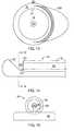
- FIGS. 14 and 15are longitudinal and transverse cross-sections of an optical bench having an occluding disk supported on a post protruding from the collection-fiber stop.
- FIG. 16is a plan view of a mask on the collection mirror.
- FIG. 17is a schematic of a perforated shell enclosing the distal tip assembly.
- FIG. 18is a schematic of a banded sheath enclosing the distal tip assembly.
- FIG. 19is a schematic of a mirror having a curved surface in optical communication with the collection fiber.
- FIGS. 20 and 21are schematics of exemplary fields-of-view as modified by mirrors having various curved surfaces.
- FIG. 22is a schematic of a lens in optical communication with the collection fiber.
- FIG. 23is a schematic of a transmissive diffracting element in optical communication with the collection fiber.
- FIG. 24is a schematic of a reflective diffractive element integrated onto the surface of the collection mirror.
- FIG. 1shows a diagnostic system 10 for identifying vulnerable plaque 12 in an arterial wall 14 of a patient.
- the diagnostic systemfeatures a catheter 16 to be inserted into a selected artery, e.g. a coronary artery, of the patient.
- a delivery fiber 18 and a collection fiber 20extend between a distal end 22 and a proximal end 24 of the catheter 16 .
- the catheter 16includes a sheath 26 surrounding a rotatable torque cable 28 .
- the delivery fiber 18extends along the center of a torque cable 28
- the collection fiber 20extends parallel to, but radially displaced from, the delivery fiber 18 .
- the rotatable torque cable 28spins at a rate between approximately 1 revolution per second and 400 revolutions per second.
- a tip assembly 30 coupled to the torque cable 28directs light traveling axially on the delivery fiber 18 toward an illumination spot 32 on the arterial wall 14 .
- the tip assembly 30also collects light from a field-of-view 34 on the arterial wall 14 and directs that light into the collection fiber 20 .
- a multi-channel coupler 36 driven by a motor 38engages the proximal end 24 of the torque cable 28 .
- the motor 38spins the multi-channel coupler 36 , both the coupler 36 , the torque cable 28 , and the tip assembly 30 spin together as a unit. This feature enables the diagnostic system 10 to circumferentially scan the arterial wall 14 with the illumination spot 32 .
- the multi-channel coupler 36guides light from a laser 40 (or other light source such as a light-emitting diode, a super-luminescent diode, or an arc lamp) into the delivery fiber 18 and guides light emerging from the collection fiber 20 into one or more detectors (not visible in FIG. 1 ).
- a laser 40or other light source such as a light-emitting diode, a super-luminescent diode, or an arc lamp
- the detectorsprovide an electrical signal indicative of light intensity to an amplifier 42 connected to an analog-to-digital (“A/D”) converter 44 .
- the A/D converter 44converts this signal into digital data that can be analyzed by a processor 46 to identify the presence of a vulnerable plaque 12 hidden beneath the arterial wall 14 .
- FIG. 3shows an optical bench 48 in which are seated the collection fiber 20 and the delivery fiber 18 .
- the optical bench 48is seated in a recess 50 between first and second side walls 52 A-B of the distal end of a housing 54 .
- the housing 54is in turn coupled to the distal end of the torque cable 28 .
- the recess 50is just wide enough to enable the collection fiber 20 and the delivery fiber 18 to nestle adjacent to each other.
- a floor 56extending between the first and second side walls 52 A-B and across the recess 50 supports both the collection and delivery fibers 18 , 20 .
- a portion of the optical bench 48forms a frustum 58 .
- the frustum 58extends transversely only half-way across the optical bench 48 , thereby enabling the collection fiber 20 to extend distally past the end of the delivery fiber 18 .
- the frustum 58has an inclined surface facing the distal end of the delivery fiber 18 and a vertical surface facing the distal end of the optical bench 48 .
- the inclined surfaceforms a 135 degree angle relative to the floor 56 . Other angles can be selected depending on the direction in which light from the delivery fiber 18 is to be directed.
- a reflective material coating the inclined surfaceforms a beam re-director, which in this case is a delivery mirror 60 . When light exits axially from the delivery fiber 18 , the delivery mirror 60 intercepts that light and redirects it radially outward to the arterial wall 14 . Examples of other beam re-directors include prisms and diffraction gratings.
- FIG. 5which illustrates the spatial distribution of light from the viewpoint of the catheter 16 , shows such a re-entrant zone 70 surrounding an illumination spot 32 .
- Photons received from within the re-entrant zone 70are predominantly those that have been scattered from within the arterial wall 14 .
- the re-entrant zone 70has an inner circumference 74 and an outer circumference 76 .
- Between the inner circumference 74 and the illumination spot 32lies a specular zone 78 .
- Photons received from the specular zone 78are predominantly those that have undergone specular reflection. Proceeding radially outward beyond the outer circumference 76 , one comes to a dark zone 80 , where the number of photons of either type is so small as to be immeasurable.
- the field-of-view 32should overlap the re-entrant zone 70 to the greatest extent possible. To the extent that the field-of-view 32 extends outside the re-entrant zone 70 , it should extend into the dark zone 80 and away from the specular zone 78 .
- the collection fiber 20extends past the end of the delivery fiber 18 until it terminates at a plane that is coplanar with the vertical face of the frustum 58 .
- a portion of the optical bench 48forms an inclined surface extending transversely across the optical bench 48 and making a 135 degree angle relative to the floor 56 .
- a reflective material coating the inclined surfaceforms a collection mirror 82 .
- This collection mirror 82reflects light incident from the arterial wall 14 into the distal end of the collection fiber 20 .
- the collection mirror 82 and the collection fiber 20together form a collection subsystem 84 that collects light from a field-of-view 32 .
- a delivery-fiber stop 86 molded into the optical bench 48 proximal to the frustum 58facilitates placement of the delivery fiber 18 at a desired location proximal to the delivery mirror 60 .
- a collection-fiber stop 88 molded into the optical bench 48 just proximal to the collection mirror 82facilitates placement of the collection fiber 20 at a desired location proximal to the collection mirror 82 .
- the collection fiberhas an optically transmissive core 90 surrounded by a protective cladding 92 .
- the collection-fiber stop 88extends upward from the floor 56 to provide an abutment surface for the collection fiber 20 .
- a portion of the cladding 92rests on the abutment surface.
- the core 90does not rest on the abutment surface and therefore remains unobstructed.
- a distal tip assembly 94 configured as shown in FIG. 6results in a field-of-view 32 shaped like an ellipse 96 with its major axis 98 extending along the radial direction, as shown in FIG. 7 .
- the extent to which the ellipse 96 overlaps the re-entrant zone 70is one measure of how effective the collection subsystem 84 is at guiding re-entrant light into the collection fiber 20 .
- the extent of the overlap between the ellipse 96 and the re-entrant zone 70depends on the eccentricity of the ellipse and its position relative to the re-entrant zone 70 .
- the eccentricity of the ellipse 96is governed by the angular orientation of the collection mirror 82 . Its position relative to the re-entrant zone 70 is controlled by varying the position and angle of the delivery mirror 60 relative to the collection mirror 82 .
- the ellipse 96is positioned to be tangent to the inner circumference 74 of the re-entrant zone 70 , with its minor axis 100 located radially outward from the point of tangency.
- FIGS. 8 and 9show an extended collection-fiber stop 102 forms an abutment surface that extends part-way across the core 90 of the collection fiber.
- the occluded portion of the core 90is bounded by a chord extending across the core 90 and by an arc that forms part of the boundary between the core 90 and the cladding 92 .
- the resulting modified field-of-viewis a truncated ellipse 106 having a base 108 , as shown in FIG. 10 .
- a dotted line 110outlines a portion 112 of the ellipse truncated by the extended collection-fiber stop 102 .
- the truncated ellipse 106is positioned such that the base 108 of the truncated ellipse 106 is tangent to the inner circumference 74 of the re-entrant zone 70 .
- the overlap between the truncated ellipse 106 and the re-entrant zone 70 in FIG. 10is greater than the overlap between the full ellipse 96 and the re-entrant zone 70 in FIG. 7 .
- the extent to which these overlaps differrepresents an increase in the number of photons gathered from the re-entrant zone 70 .
- FIGS. 11 and 12Other beam-shaping structures can be used to prevent light from illuminating the entire core 90 and to thereby shape the field-of-view 32 .
- a tab 118 having a curved distal tip 119protrudes vertically upward from the collection-fiber stop 88 and obstructs part of the core 90 .
- FIGS. 14 and 15Another example, shown in FIGS. 14 and 15 , is an occulting disk 122 mounted on a post 124 that protrudes from the collection-fiber stop 88 .
- the post 124supports the occulting disk 122 so that its center coincides with the center of the core 90 .
- the diameter of the occulting disk 122is slightly smaller than the diameter of the core 90 .
- the difference between the diameter of the occulting disk 122 and that of the core 90is selected to provide an annular field-of-view that closely matches the size and shape of the re-entrant zone 70 .
- Structures that effectively block light from entering a portion of the collection fiberneed not be adjacent to the collection fiber 20 , as shown in FIGS. 11-12 and in FIGS. 14-15 .
- such structurescan be placed anywhere along the optical path between the collection fiber 20 and the arterial wall 14 .
- a beam-shaping structure that effectively obstructs a portion of the core 90can be a mask 125 formed directly on the collection mirror 82 , as shown in FIG. 16 .
- Another example of such a structureis a perforated shell 127 rotationally coupled to the torque cable 28 , as shown in FIG. 17 .
- the perforated shell 127has a delivery aperture 129 to permit light from the delivery fiber 18 to pass through the shell 127 unimpeded, and a collection aperture 131 shaped to block a portion of the light incident on the collection mirror 82 .
- an opaque band 133 on a transparent distal tip 135 of the stationary sheath 26is positioned to obscure a portion of the collection mirror 82 .
- the band 131extends circumferentially around the sheath so that the collection mirror 82 is obscured as the torque cable 28 rotates the collection mirror 82 .
- any of the foregoing beam-shaping structurescan have an edge that is modified to diffract light incident thereon in a manner that causes the field-of-view to have a pre-selected geometry.
- Such an edgecan be formed by providing protrusions or indentations having a dimension on the order of the wavelength of light to be observed.
- the beam-shaping function of the foregoing obstructionscan also be achieved by providing an optical system in optical communication with the collection mirror 82 .
- Such an optical systemcan include a collection mirror 82 with a curved surface, a lens assembly, or both.
- the collection mirror 82has a cylindrical surface rather than a planar surface.
- the resulting field-of-view for the configuration shown in FIG. 19is an ellipse 126 having an aspect ratio closer to unity, as shown in FIG. 20 .
- Other curved surfacescan result in fields-of-view or alternatively an ellipse 128 in which it is the minor axis of an ellipse 128 , rather than the major axis, that extends radially, as shown in FIG. 21 .
- Curved surfaces other than a cylindrical surfacecan also be used to shape the field-of-view to more closely approximate the shape of the re-entrant zone 70 .
- the curved surfacecan be a conic surface, such as a paraboloid, a hyperboloid, or an ellipsoid.
- the surfacecan be a spherical surface.
- Optical elements other than reflecting surfacescan also be used to shape the field-of-view.
- a lens assembly 130 disposed in optical communication with the collection fiber 20provides control over the shape of the field-of-view.
- the lens assembly 130can include one or more discrete lenses.
- One or more lenses in the lens assemblycan have a suitably curved surface.
- Another lens suitable for use in a lens assemblyis a GRIN (graduated index of refraction) lens having a spatially varying index of refraction.
- the lens assembly 130need not be composed of discrete lenses but can instead include a lens that is integral with the distal end of the collection fiber 20 .
- Such a lens 132an example of which is shown in FIG. 22 , can be made by shaping the distal end of the collection fiber 20 so that it has the desired optical characteristics.
- the beam-shaping function provided by the foregoing examples of optical systemscan also be provided by a diffracting element 134 placed along the optical path, as shown in FIG. 23 .
- diffracting elements 134include diffraction gratings, amplitude gratings, spatial light modulators, and holographic gratings.
- the diffracting elementcan be a transmissive or reflective.
- a transmissive diffracting element 134can be placed anywhere along the optical path traversed by the collection beam, either integrated onto the distal end of the collection fiber 20 , as shown in FIG. 23 , or mounted separately on the optical path, either between the collection fiber 20 and the mirror 82 as shown in FIG. 23 , or between the collection mirror 82 and the arterial wall.
- a reflective diffracting element 134can be integrated directly onto the surface of the collection mirror 82 as shown in FIG. 24 .
- the surfaces of the delivery and collection mirrors 60 , 82can be coated with a reflective coating, such as gold, silver or aluminum. These coatings can be applied by known vapor deposition techniques. Alternatively, for certain types of plastic, a reflective coating can be electroplated onto those surfaces. Or, the plastic itself can have a reflective filler, such as gold or aluminum powder, incorporated within it.
- a reflective coatingsuch as gold, silver or aluminum.
- the optical bench 48is manufactured by injection molding a plastic into a mold. In addition to being simple and inexpensive, the injection molding process makes it easy to integrate the elements of the optical bench 48 into a single monolith and to fashion structures having curved surfaces.
- suitable plasticsinclude liquid crystal polymers (LCPs), polyphenylsulfone, polycarbonate, acrylonitrile butadiene-styrene (“ABS”), polyamide (“NYLON”), polyethersulfone, and polyetherimide.
- the optical benchcan be manufactured by micro-machining plastic or metal, by lithographic methods, by etching, by silicon optical bench fabrication techniques, or by injection molding metal. Materials other than plastics can be used to manufacture the housing 54 and the optical bench 48 . Such materials include metals, quartz or glass, and ceramics.
- the floor 56 in the illustrated embodimentis integral to the housing 54 .
- the floor 56can also be made part of the optical bench 48 .
- the housing 54 and the optical bench 48are manufactured separately and later joined. However, the housing 54 and the optical bench 48 can also be manufactured together as a single unitary structure.
- the distal tip assembly 94is inserted into a blood vessel, typically an artery, and guided to a location of interest. Light is then directed into the delivery fiber 18 . This light exits the delivery fiber 18 at its distal tip, reflects off the delivery mirror 60 in a direction away from the plane containing the delivery and collection fibers 18 , 20 , and illuminates an illumination spot 32 on the wall of the artery. Light penetrating the arterial wall 14 is then scattered by structures within the wall. Some of this scattered light re-enters the blood vessel and impinges on the plane and onto the collection mirror 82 . The collection mirror 82 directs this light into the collection fiber 20 .
- light incident on the wall 14can stimulate fluorescence from structures on or within the wall 14 .
- the portion of this fluorescent light that is incident on the collection mirror 82is directed into the collection fiber 20 .
Landscapes
- Health & Medical Sciences (AREA)
- Life Sciences & Earth Sciences (AREA)
- Physics & Mathematics (AREA)
- General Health & Medical Sciences (AREA)
- Veterinary Medicine (AREA)
- Engineering & Computer Science (AREA)
- Biomedical Technology (AREA)
- Heart & Thoracic Surgery (AREA)
- Medical Informatics (AREA)
- Molecular Biology (AREA)
- Surgery (AREA)
- Animal Behavior & Ethology (AREA)
- Biophysics (AREA)
- Public Health (AREA)
- Pathology (AREA)
- Vascular Medicine (AREA)
- Cardiology (AREA)
- Physiology (AREA)
- Nuclear Medicine, Radiotherapy & Molecular Imaging (AREA)
- Radiology & Medical Imaging (AREA)
- Spectroscopy & Molecular Physics (AREA)
- Investigating Or Analysing Materials By Optical Means (AREA)
- Instruments For Viewing The Inside Of Hollow Bodies (AREA)
- Endoscopes (AREA)
Abstract
Description
Claims (29)
Priority Applications (1)
| Application Number | Priority Date | Filing Date | Title |
|---|---|---|---|
| US11/772,887US7873406B2 (en) | 2002-11-07 | 2007-07-03 | Spectroscope for recovering light from re-entrant zone of arterial wall |
Applications Claiming Priority (2)
| Application Number | Priority Date | Filing Date | Title |
|---|---|---|---|
| US10/289,741US20040092829A1 (en) | 2002-11-07 | 2002-11-07 | Spectroscope with modified field-of-view |
| US11/772,887US7873406B2 (en) | 2002-11-07 | 2007-07-03 | Spectroscope for recovering light from re-entrant zone of arterial wall |
Related Parent Applications (1)
| Application Number | Title | Priority Date | Filing Date |
|---|---|---|---|
| US10/289,741DivisionUS20040092829A1 (en) | 2002-11-07 | 2002-11-07 | Spectroscope with modified field-of-view |
Publications (2)
| Publication Number | Publication Date |
|---|---|
| US20070255142A1 US20070255142A1 (en) | 2007-11-01 |
| US7873406B2true US7873406B2 (en) | 2011-01-18 |
Family
ID=32228924
Family Applications (3)
| Application Number | Title | Priority Date | Filing Date |
|---|---|---|---|
| US10/289,741AbandonedUS20040092829A1 (en) | 2002-11-07 | 2002-11-07 | Spectroscope with modified field-of-view |
| US11/772,887Expired - LifetimeUS7873406B2 (en) | 2002-11-07 | 2007-07-03 | Spectroscope for recovering light from re-entrant zone of arterial wall |
| US12/641,811AbandonedUS20100160792A1 (en) | 2002-11-07 | 2009-12-18 | Spectroscope With Modified Field-of-View |
Family Applications Before (1)
| Application Number | Title | Priority Date | Filing Date |
|---|---|---|---|
| US10/289,741AbandonedUS20040092829A1 (en) | 2002-11-07 | 2002-11-07 | Spectroscope with modified field-of-view |
Family Applications After (1)
| Application Number | Title | Priority Date | Filing Date |
|---|---|---|---|
| US12/641,811AbandonedUS20100160792A1 (en) | 2002-11-07 | 2009-12-18 | Spectroscope With Modified Field-of-View |
Country Status (5)
| Country | Link |
|---|---|
| US (3) | US20040092829A1 (en) |
| EP (1) | EP1558127A4 (en) |
| JP (2) | JP2006505360A (en) |
| AU (1) | AU2003291401A1 (en) |
| WO (1) | WO2004043251A1 (en) |
Cited By (3)
| Publication number | Priority date | Publication date | Assignee | Title |
|---|---|---|---|---|
| US8958867B2 (en) | 2011-08-29 | 2015-02-17 | Infraredx, Inc. | Detection of lipid core plaque cap thickness |
| US10776654B2 (en) | 2015-03-10 | 2020-09-15 | Infraredx, Inc. | Assessment of lipid core plaque integrity |
| WO2025166121A1 (en) | 2024-02-02 | 2025-08-07 | Infraredx, Inc. | Intravascular optical diffuse blood flow correlation spectroscopy |
Families Citing this family (59)
| Publication number | Priority date | Publication date | Assignee | Title |
|---|---|---|---|---|
| US7231243B2 (en) | 2000-10-30 | 2007-06-12 | The General Hospital Corporation | Optical methods for tissue analysis |
| WO2004081865A2 (en)* | 2003-03-10 | 2004-09-23 | University Of Iowa Research Foundation | Systems and methods for bioliminescent computed tomographic reconstruction |
| EP2436307B1 (en) | 2003-03-31 | 2015-10-21 | The General Hospital Corporation | Speckle reduction in optical coherence tomography by path length encoded angular compounding |
| US7267648B2 (en)* | 2003-03-31 | 2007-09-11 | Olympus Corporation | Magnifying image pickup unit for an endoscope, an endoscope for in vivo cellular observation that uses it, and endoscopic, in vivo cellular observation methods |
| KR101386971B1 (en) | 2003-06-06 | 2014-04-18 | 더 제너럴 하스피탈 코포레이션 | Process and apparatus for a wavelength tunning source |
| AU2005270037B2 (en) | 2004-07-02 | 2012-02-09 | The General Hospital Corporation | Endoscopic imaging probe comprising dual clad fibre |
| EP2272421A1 (en) | 2004-08-24 | 2011-01-12 | The General Hospital Corporation | Method and apparatus for imaging of vessel segments |
| WO2006024014A2 (en) | 2004-08-24 | 2006-03-02 | The General Hospital Corporation | Process, system and software arrangement for measuring a mechanical strain and elastic properties of a sample |
| WO2006050453A1 (en)* | 2004-11-02 | 2006-05-11 | The General Hospital Corporation | Fiber-optic rotational device, optical system and method for imaging a sample |
| JP5695001B2 (en)* | 2004-11-02 | 2015-04-01 | ザ ジェネラル ホスピタル コーポレイション | Optical fiber rotator, optical system and method for sample imaging |
| WO2006058346A1 (en) | 2004-11-29 | 2006-06-01 | The General Hospital Corporation | Arrangements, devices, endoscopes, catheters and methods for performing optical imaging by simultaneously illuminating and detecting multiple points on a sample |
| ES2337497T3 (en) | 2005-04-28 | 2010-04-26 | The General Hospital Corporation | EVALUATION OF CHARACTERISTICS OF THE IMAGE OF AN ANATOMICAL STRUCTURE IN IMAGES OF TOMOGRAPHY OF OPTICAL COHERENCE. |
| US20070093700A1 (en)* | 2005-05-31 | 2007-04-26 | Ge Wang | Computational optical biopsy |
| US9060689B2 (en) | 2005-06-01 | 2015-06-23 | The General Hospital Corporation | Apparatus, method and system for performing phase-resolved optical frequency domain imaging |
| EP2267404B1 (en) | 2005-08-09 | 2016-10-05 | The General Hospital Corporation | Apparatus and method for performing polarization-based quadrature demodulation in optical coherence tomography |
| US7843572B2 (en) | 2005-09-29 | 2010-11-30 | The General Hospital Corporation | Method and apparatus for optical imaging via spectral encoding |
| DK1973466T3 (en) | 2006-01-19 | 2021-02-01 | Massachusetts Gen Hospital | BALLOON IMAGING CATHETER |
| US8145018B2 (en) | 2006-01-19 | 2012-03-27 | The General Hospital Corporation | Apparatus for obtaining information for a structure using spectrally-encoded endoscopy techniques and methods for producing one or more optical arrangements |
| WO2007149602A2 (en) | 2006-02-01 | 2007-12-27 | The General Hospital Corporation | Methods and systems for providing electromagnetic radiation to at least one portion of a sample using conformal laser therapy procedures |
| JP5680829B2 (en) | 2006-02-01 | 2015-03-04 | ザ ジェネラル ホスピタル コーポレイション | A device that irradiates a sample with multiple electromagnetic radiations |
| EP2982929A1 (en) | 2006-02-24 | 2016-02-10 | The General Hospital Corporation | Methods and systems for performing angle-resolved fourier-domain optical coherence tomography |
| WO2007105495A1 (en)* | 2006-03-13 | 2007-09-20 | Olympus Medical Systems Corp. | Scattering medium inside observing device, imaging system, imaging method, and endoscope |
| JP2007260122A (en)* | 2006-03-28 | 2007-10-11 | Olympus Medical Systems Corp | Scattering medium internal observation device |
| WO2007133961A2 (en) | 2006-05-10 | 2007-11-22 | The General Hospital Corporation | Processes, arrangements and systems for providing frequency domain imaging of a sample |
| JP5314841B2 (en)* | 2006-08-22 | 2013-10-16 | オリンパス株式会社 | Endoscope device and endoscope probe |
| US8838213B2 (en) | 2006-10-19 | 2014-09-16 | The General Hospital Corporation | Apparatus and method for obtaining and providing imaging information associated with at least one portion of a sample, and effecting such portion(s) |
| US10534129B2 (en) | 2007-03-30 | 2020-01-14 | The General Hospital Corporation | System and method providing intracoronary laser speckle imaging for the detection of vulnerable plaque |
| WO2010009136A2 (en) | 2008-07-14 | 2010-01-21 | The General Hospital Corporation | Apparatus and methods for color endoscopy |
| JP5731394B2 (en) | 2008-12-10 | 2015-06-10 | ザ ジェネラル ホスピタル コーポレイション | System, apparatus and method for extending imaging depth range of optical coherence tomography through optical subsampling |
| JP2012515576A (en) | 2009-01-20 | 2012-07-12 | ザ ジェネラル ホスピタル コーポレイション | Endoscopic biopsy device, system, and method |
| CA2749670A1 (en) | 2009-02-04 | 2010-08-12 | The General Hospital Corporation | Apparatus and method for utilization of a high-speed optical wavelength tuning source |
| JP5819823B2 (en) | 2009-07-14 | 2015-11-24 | ザ ジェネラル ホスピタル コーポレイション | Device for measuring the flow and pressure inside a blood vessel and method of operating the device |
| KR20130004326A (en) | 2010-03-05 | 2013-01-09 | 더 제너럴 하스피탈 코포레이션 | Systems, methods and computer-accessible medium which provide microscopic images of at least one anatomical structure at a particular resolution |
| US9069130B2 (en) | 2010-05-03 | 2015-06-30 | The General Hospital Corporation | Apparatus, method and system for generating optical radiation from biological gain media |
| EP2575598A2 (en) | 2010-05-25 | 2013-04-10 | The General Hospital Corporation | Apparatus, systems, methods and computer-accessible medium for spectral analysis of optical coherence tomography images |
| EP2575597B1 (en) | 2010-05-25 | 2022-05-04 | The General Hospital Corporation | Apparatus for providing optical imaging of structures and compositions |
| JP6066901B2 (en) | 2010-06-03 | 2017-01-25 | ザ ジェネラル ホスピタル コーポレイション | Method for apparatus and device for imaging structures in or in one or more luminal organs |
| WO2012058381A2 (en) | 2010-10-27 | 2012-05-03 | The General Hospital Corporation | Apparatus, systems and methods for measuring blood pressure within at least one vessel |
| US9330092B2 (en) | 2011-07-19 | 2016-05-03 | The General Hospital Corporation | Systems, methods, apparatus and computer-accessible-medium for providing polarization-mode dispersion compensation in optical coherence tomography |
| JP2015502562A (en) | 2011-10-18 | 2015-01-22 | ザ ジェネラル ホスピタル コーポレイション | Apparatus and method for generating and / or providing recirculating optical delay |
| WO2013148306A1 (en) | 2012-03-30 | 2013-10-03 | The General Hospital Corporation | Imaging system, method and distal attachment for multidirectional field of view endoscopy |
| JP2015517387A (en) | 2012-05-21 | 2015-06-22 | ザ ジェネラル ホスピタル コーポレイション | Apparatus, device and method for capsule microscopy |
| JP6227652B2 (en) | 2012-08-22 | 2017-11-08 | ザ ジェネラル ホスピタル コーポレイション | System, method, and computer-accessible medium for fabricating a miniature endoscope using soft lithography |
| US9968261B2 (en) | 2013-01-28 | 2018-05-15 | The General Hospital Corporation | Apparatus and method for providing diffuse spectroscopy co-registered with optical frequency domain imaging |
| WO2014120791A1 (en) | 2013-01-29 | 2014-08-07 | The General Hospital Corporation | Apparatus, systems and methods for providing information regarding the aortic valve |
| US11179028B2 (en) | 2013-02-01 | 2021-11-23 | The General Hospital Corporation | Objective lens arrangement for confocal endomicroscopy |
| US10478072B2 (en) | 2013-03-15 | 2019-11-19 | The General Hospital Corporation | Methods and system for characterizing an object |
| CA2908662C (en)* | 2013-04-06 | 2021-08-03 | Miranda Technologies Partnership | Systems and methods for media distribution and management |
| EP2997354A4 (en) | 2013-05-13 | 2017-01-18 | The General Hospital Corporation | Detecting self-interefering fluorescence phase and amplitude |
| EP3021735A4 (en) | 2013-07-19 | 2017-04-19 | The General Hospital Corporation | Determining eye motion by imaging retina. with feedback |
| WO2015009932A1 (en) | 2013-07-19 | 2015-01-22 | The General Hospital Corporation | Imaging apparatus and method which utilizes multidirectional field of view endoscopy |
| WO2015013651A2 (en) | 2013-07-26 | 2015-01-29 | The General Hospital Corporation | System, apparatus and method utilizing optical dispersion for fourier-domain optical coherence tomography |
| WO2015105870A1 (en) | 2014-01-08 | 2015-07-16 | The General Hospital Corporation | Method and apparatus for microscopic imaging |
| US10736494B2 (en) | 2014-01-31 | 2020-08-11 | The General Hospital Corporation | System and method for facilitating manual and/or automatic volumetric imaging with real-time tension or force feedback using a tethered imaging device |
| WO2015153982A1 (en) | 2014-04-04 | 2015-10-08 | The General Hospital Corporation | Apparatus and method for controlling propagation and/or transmission of electromagnetic radiation in flexible waveguide(s) |
| US9709713B1 (en)* | 2014-06-18 | 2017-07-18 | Peter C. Chen | High quality telescope mirrors made from polymer matrix composite materials and method |
| US10912462B2 (en) | 2014-07-25 | 2021-02-09 | The General Hospital Corporation | Apparatus, devices and methods for in vivo imaging and diagnosis |
| RU2752690C2 (en) | 2016-06-29 | 2021-07-29 | Конинклейке Филипс Н.В. | Detecting changes in medical imaging |
| EP3521892A4 (en)* | 2016-09-29 | 2020-07-29 | Olympus Corporation | Observation device |
Citations (41)
| Publication number | Priority date | Publication date | Assignee | Title |
|---|---|---|---|---|
| US4573761A (en) | 1983-09-14 | 1986-03-04 | The Dow Chemical Company | Fiber-optic probe for sensitive Raman analysis |
| US4705354A (en) | 1984-08-09 | 1987-11-10 | Daimler-Benz Aktiengesellschaft | Method for fiber optic transmission of a special coded measurement |
| US4768873A (en) | 1985-09-17 | 1988-09-06 | Eye Research Institute Of Retina Foundation | Double scanning optical apparatus and method |
| US4768513A (en) | 1986-04-21 | 1988-09-06 | Agency Of Industrial Science And Technology | Method and device for measuring and processing light |
| US4838643A (en) | 1988-03-23 | 1989-06-13 | Alcatel Na, Inc. | Single mode bend insensitive fiber for use in fiber optic guidance applications |
| US4896941A (en) | 1985-04-27 | 1990-01-30 | Doryokuro Kakunenryo Kaihatsu Jigyodan | Image-transmitting fiber |
| US4921326A (en) | 1989-03-23 | 1990-05-01 | Victor F. Wild | Fiber optic probe |
| US4991947A (en) | 1988-10-05 | 1991-02-12 | Carl-Zeiss-Stiftung | Two optomechanically coupled surgical microscopes with coaxial illumination |
| US5057695A (en) | 1988-12-19 | 1991-10-15 | Otsuka Electronics Co., Ltd. | Method of and apparatus for measuring the inside information of substance with the use of light scattering |
| US5106387A (en) | 1985-03-22 | 1992-04-21 | Massachusetts Institute Of Technology | Method for spectroscopic diagnosis of tissue |
| US5127079A (en) | 1990-02-23 | 1992-06-30 | Mitsubishi Rayon Company Ltd. | Multifilament type plastic optical fiber endoscope |
| US5261904A (en) | 1990-01-30 | 1993-11-16 | C. R. Bard, Inc. | Laser catheter having diffraction grating for beam shaping |
| US5318024A (en)* | 1985-03-22 | 1994-06-07 | Massachusetts Institute Of Technology | Laser endoscope for spectroscopic imaging |
| US5418880A (en) | 1994-07-29 | 1995-05-23 | Polaroid Corporation | High-power optical fiber amplifier or laser device |
| US5452723A (en) | 1992-07-24 | 1995-09-26 | Massachusetts Institute Of Technology | Calibrated spectrographic imaging |
| US5537499A (en) | 1994-08-18 | 1996-07-16 | Laser Peripherals, Inc. | Side-firing laser optical fiber probe and method of making same |
| US5551422A (en) | 1992-11-09 | 1996-09-03 | Boehringer Mannheim Gmbh | Method and apparatus for analytical determination of glucose in a biological matrix |
| US5566196A (en) | 1994-10-27 | 1996-10-15 | Sdl, Inc. | Multiple core fiber laser and optical amplifier |
| US5636633A (en) | 1995-08-09 | 1997-06-10 | Rio Grande Medical Technologies, Inc. | Diffuse reflectance monitoring apparatus |
| US5713364A (en) | 1995-08-01 | 1998-02-03 | Medispectra, Inc. | Spectral volume microprobe analysis of materials |
| US5764840A (en) | 1995-11-20 | 1998-06-09 | Visionex, Inc. | Optical fiber with enhanced light collection and illumination and having highly controlled emission and acceptance patterns |
| US5813987A (en)* | 1995-08-01 | 1998-09-29 | Medispectra, Inc. | Spectral volume microprobe for analysis of materials |
| US5838860A (en) | 1993-05-21 | 1998-11-17 | Super Vision International, Inc. | Fiber optic light source apparatus and method |
| US5880880A (en) | 1995-01-13 | 1999-03-09 | The General Hospital Corp. | Three-dimensional scanning confocal laser microscope |
| US5901261A (en) | 1997-06-19 | 1999-05-04 | Visionex, Inc. | Fiber optic interface for optical probes with enhanced photonic efficiency, light manipulation, and stray light rejection |
| US5911017A (en) | 1996-07-31 | 1999-06-08 | Visionex, Inc. | Fiber optic interface for laser spectroscopic Raman probes |
| US5926592A (en) | 1995-03-24 | 1999-07-20 | Optiscan Pty Ltd | Optical fibre confocal imager with variable near-confocal control |
| US5953477A (en) | 1995-11-20 | 1999-09-14 | Visionex, Inc. | Method and apparatus for improved fiber optic light management |
| US5973828A (en) | 1997-05-30 | 1999-10-26 | The General Hospital Corporation | Confocal scanning microscope with angled objective lenses for improved axial resolution |
| US6014204A (en) | 1998-01-23 | 2000-01-11 | Providence Health System | Multiple diameter fiber optic device and process of using the same |
| WO2000013578A1 (en) | 1998-09-03 | 2000-03-16 | Hypermed Imaging, Inc. | Infrared endoscopic balloon probes |
| US6081371A (en) | 1998-01-06 | 2000-06-27 | Olympus Optical Co., Ltd. | Surgical microscope including a first image and a changing projection position of a second image |
| US6121603A (en) | 1997-12-01 | 2000-09-19 | Hang; Zhijiang | Optical confocal device having a common light directing means |
| US6151428A (en) | 1996-11-07 | 2000-11-21 | California Institute Of Technology | All-optical wavelength coded logic gates |
| US6157763A (en) | 1998-01-28 | 2000-12-05 | Sdl, Inc. | Double-clad optical fiber with improved inner cladding geometry |
| US6564087B1 (en) | 1991-04-29 | 2003-05-13 | Massachusetts Institute Of Technology | Fiber optic needle probes for optical coherence tomography imaging |
| US6564088B1 (en) | 2000-01-21 | 2003-05-13 | University Of Massachusetts | Probe for localized tissue spectroscopy |
| US6643065B1 (en)* | 2001-01-18 | 2003-11-04 | Donn Michael Silberman | Variable spacing diffraction grating |
| US6654630B2 (en)* | 2001-05-31 | 2003-11-25 | Infraredx, Inc. | Apparatus and method for the optical imaging of tissue samples |
| US7426410B2 (en)* | 2003-06-06 | 2008-09-16 | Infraredx, Inc. | Spectroscopy of deeply-scattered light |
| US7466421B2 (en)* | 2002-07-15 | 2008-12-16 | Campus Technologies Ag | Diffractive interferometric optical device for measuring spectral properties of light |
Family Cites Families (14)
| Publication number | Priority date | Publication date | Assignee | Title |
|---|---|---|---|---|
| US611580A (en)* | 1898-09-27 | Ludwig rissmtjller | ||
| CA1279901C (en)* | 1985-03-22 | 1991-02-05 | Carter Kittrell | Catheter for laser angiosurgery |
| JPS62105017A (en)* | 1985-10-31 | 1987-05-15 | Shimadzu Corp | spectrophotometer |
| JPS63234940A (en)* | 1987-03-25 | 1988-09-30 | 株式会社東芝 | color measurement device |
| US6134003A (en)* | 1991-04-29 | 2000-10-17 | Massachusetts Institute Of Technology | Method and apparatus for performing optical measurements using a fiber optic imaging guidewire, catheter or endoscope |
| JPH0650818A (en)* | 1992-07-29 | 1994-02-25 | Minolta Camera Co Ltd | Measuring device for color |
| JP3368015B2 (en)* | 1992-11-20 | 2003-01-20 | キヤノン株式会社 | Optical heterodyne interferometer |
| WO1996023197A1 (en)* | 1995-01-24 | 1996-08-01 | Massachusetts Institute Of Technology | Device and method for time-resolved optical measurements |
| JP4021975B2 (en)* | 1997-08-28 | 2007-12-12 | オリンパス株式会社 | Optical scanning probe device |
| JP2000206047A (en)* | 1999-01-08 | 2000-07-28 | Fuji Photo Film Co Ltd | Spectrum-measuring device |
| JP3717719B2 (en)* | 1999-08-23 | 2005-11-16 | オリンパス株式会社 | Endoscope light source device |
| JP2001349993A (en)* | 2000-04-07 | 2001-12-21 | Fuji Photo Film Co Ltd | Image reader |
| JP2001311880A (en)* | 2000-04-28 | 2001-11-09 | Olympus Optical Co Ltd | Compact confocal optical system |
| JP2002013981A (en)* | 2000-06-28 | 2002-01-18 | Minolta Co Ltd | Photometer |
- 2002
- 2002-11-07USUS10/289,741patent/US20040092829A1/ennot_activeAbandoned
- 2003
- 2003-11-07WOPCT/US2003/035692patent/WO2004043251A1/enactiveApplication Filing
- 2003-11-07AUAU2003291401Apatent/AU2003291401A1/ennot_activeAbandoned
- 2003-11-07EPEP03768797Apatent/EP1558127A4/ennot_activeWithdrawn
- 2003-11-07JPJP2004551957Apatent/JP2006505360A/enactivePending
- 2007
- 2007-07-03USUS11/772,887patent/US7873406B2/ennot_activeExpired - Lifetime
- 2009
- 2009-12-18USUS12/641,811patent/US20100160792A1/ennot_activeAbandoned
- 2010
- 2010-01-06JPJP2010000840Apatent/JP2010142649A/enactivePending
Patent Citations (45)
| Publication number | Priority date | Publication date | Assignee | Title |
|---|---|---|---|---|
| US4573761A (en) | 1983-09-14 | 1986-03-04 | The Dow Chemical Company | Fiber-optic probe for sensitive Raman analysis |
| US4705354A (en) | 1984-08-09 | 1987-11-10 | Daimler-Benz Aktiengesellschaft | Method for fiber optic transmission of a special coded measurement |
| US5106387A (en) | 1985-03-22 | 1992-04-21 | Massachusetts Institute Of Technology | Method for spectroscopic diagnosis of tissue |
| US5318024A (en)* | 1985-03-22 | 1994-06-07 | Massachusetts Institute Of Technology | Laser endoscope for spectroscopic imaging |
| US4896941A (en) | 1985-04-27 | 1990-01-30 | Doryokuro Kakunenryo Kaihatsu Jigyodan | Image-transmitting fiber |
| US4768873A (en) | 1985-09-17 | 1988-09-06 | Eye Research Institute Of Retina Foundation | Double scanning optical apparatus and method |
| US4768513A (en) | 1986-04-21 | 1988-09-06 | Agency Of Industrial Science And Technology | Method and device for measuring and processing light |
| US4838643A (en) | 1988-03-23 | 1989-06-13 | Alcatel Na, Inc. | Single mode bend insensitive fiber for use in fiber optic guidance applications |
| US4991947A (en) | 1988-10-05 | 1991-02-12 | Carl-Zeiss-Stiftung | Two optomechanically coupled surgical microscopes with coaxial illumination |
| US5057695A (en) | 1988-12-19 | 1991-10-15 | Otsuka Electronics Co., Ltd. | Method of and apparatus for measuring the inside information of substance with the use of light scattering |
| US4921326A (en) | 1989-03-23 | 1990-05-01 | Victor F. Wild | Fiber optic probe |
| US5261904A (en) | 1990-01-30 | 1993-11-16 | C. R. Bard, Inc. | Laser catheter having diffraction grating for beam shaping |
| US5127079A (en) | 1990-02-23 | 1992-06-30 | Mitsubishi Rayon Company Ltd. | Multifilament type plastic optical fiber endoscope |
| US6564087B1 (en) | 1991-04-29 | 2003-05-13 | Massachusetts Institute Of Technology | Fiber optic needle probes for optical coherence tomography imaging |
| US5452723A (en) | 1992-07-24 | 1995-09-26 | Massachusetts Institute Of Technology | Calibrated spectrographic imaging |
| US5551422A (en) | 1992-11-09 | 1996-09-03 | Boehringer Mannheim Gmbh | Method and apparatus for analytical determination of glucose in a biological matrix |
| US5838860A (en) | 1993-05-21 | 1998-11-17 | Super Vision International, Inc. | Fiber optic light source apparatus and method |
| US5418880A (en) | 1994-07-29 | 1995-05-23 | Polaroid Corporation | High-power optical fiber amplifier or laser device |
| US5537499A (en) | 1994-08-18 | 1996-07-16 | Laser Peripherals, Inc. | Side-firing laser optical fiber probe and method of making same |
| US5566196A (en) | 1994-10-27 | 1996-10-15 | Sdl, Inc. | Multiple core fiber laser and optical amplifier |
| US5995283A (en) | 1995-01-13 | 1999-11-30 | General Hospital Corporation | Three-dimensional scanning confocal laser microscope |
| US5880880A (en) | 1995-01-13 | 1999-03-09 | The General Hospital Corp. | Three-dimensional scanning confocal laser microscope |
| US5926592A (en) | 1995-03-24 | 1999-07-20 | Optiscan Pty Ltd | Optical fibre confocal imager with variable near-confocal control |
| US5713364A (en) | 1995-08-01 | 1998-02-03 | Medispectra, Inc. | Spectral volume microprobe analysis of materials |
| US5813987A (en)* | 1995-08-01 | 1998-09-29 | Medispectra, Inc. | Spectral volume microprobe for analysis of materials |
| US5636633A (en) | 1995-08-09 | 1997-06-10 | Rio Grande Medical Technologies, Inc. | Diffuse reflectance monitoring apparatus |
| US5878178A (en) | 1995-11-20 | 1999-03-02 | Visionex Inc | Optical fiber with enhanced light collection and illumination and having highly controlled emission and acceptance patterns |
| US5953477A (en) | 1995-11-20 | 1999-09-14 | Visionex, Inc. | Method and apparatus for improved fiber optic light management |
| US5764840A (en) | 1995-11-20 | 1998-06-09 | Visionex, Inc. | Optical fiber with enhanced light collection and illumination and having highly controlled emission and acceptance patterns |
| US6144791A (en)* | 1995-11-20 | 2000-11-07 | Cirrex Corp. | Beam steering for optical fibers and other related devices |
| US5911017A (en) | 1996-07-31 | 1999-06-08 | Visionex, Inc. | Fiber optic interface for laser spectroscopic Raman probes |
| US6151428A (en) | 1996-11-07 | 2000-11-21 | California Institute Of Technology | All-optical wavelength coded logic gates |
| US5973828A (en) | 1997-05-30 | 1999-10-26 | The General Hospital Corporation | Confocal scanning microscope with angled objective lenses for improved axial resolution |
| US6118580A (en) | 1997-05-30 | 2000-09-12 | The General Hospital Corporation | Confocal scanning microscope with angled objective lenses for improved axial resolution |
| US5901261A (en) | 1997-06-19 | 1999-05-04 | Visionex, Inc. | Fiber optic interface for optical probes with enhanced photonic efficiency, light manipulation, and stray light rejection |
| US6121603A (en) | 1997-12-01 | 2000-09-19 | Hang; Zhijiang | Optical confocal device having a common light directing means |
| US6081371A (en) | 1998-01-06 | 2000-06-27 | Olympus Optical Co., Ltd. | Surgical microscope including a first image and a changing projection position of a second image |
| US6014204A (en) | 1998-01-23 | 2000-01-11 | Providence Health System | Multiple diameter fiber optic device and process of using the same |
| US6157763A (en) | 1998-01-28 | 2000-12-05 | Sdl, Inc. | Double-clad optical fiber with improved inner cladding geometry |
| WO2000013578A1 (en) | 1998-09-03 | 2000-03-16 | Hypermed Imaging, Inc. | Infrared endoscopic balloon probes |
| US6564088B1 (en) | 2000-01-21 | 2003-05-13 | University Of Massachusetts | Probe for localized tissue spectroscopy |
| US6643065B1 (en)* | 2001-01-18 | 2003-11-04 | Donn Michael Silberman | Variable spacing diffraction grating |
| US6654630B2 (en)* | 2001-05-31 | 2003-11-25 | Infraredx, Inc. | Apparatus and method for the optical imaging of tissue samples |
| US7466421B2 (en)* | 2002-07-15 | 2008-12-16 | Campus Technologies Ag | Diffractive interferometric optical device for measuring spectral properties of light |
| US7426410B2 (en)* | 2003-06-06 | 2008-09-16 | Infraredx, Inc. | Spectroscopy of deeply-scattered light |
Non-Patent Citations (13)
| Title |
|---|
| "Coronary-Artery Bypass Surgery," The Lancet, pp. 264-265 (Feb. 4, 1978). |
| Barber et al., "Ultrasonic Duplex Echo-Doppler Scanner," IEEE Transactions on Biomedical Engineering, vol. BME-21, No. 2, pp. 109-113 (Mar. 1974). |
| Bow et al., "Cardiac Imaging with a Real-Time Ultrasonic Scanner of a Rotating Transducer Design," Proceedings of the British Medical Ultrasound Society, p. 645 (Aug. 1978). |
| Hisanaga et al., "High Speed Rotating Scanner for Transesophageal Cross-Sectional Echocardiography," The American Journal of Cardiology, vol. 46, pp. 837-842 (Nov. 1980). |
| Lancée et al., "Construction of a circular ultrasonic array with miniature elements for cardiac application." Thorax Center, Department of Echocardiography and Central Research Workshop, Erasmus University, Rotterdam, The Netherlands, pp. 49-53 (undated). |
| Martin and Watkins, "An Ultrasonic Catheter for Intravascular Measurement of Blood Flow: Technical Details," IEEE Transactions on Sonics and Ultrasonics, vol. SU-27, No. 6, pp. 277-286 (Nov. 1980). |
| Martin et al., "An Ultrasonic Catheter Tip Instrument for Measuring Volume Blood Flow," Departments of Anesthesiology & Bioengineering, University of Washington, Seattle, Washington, pp. 13-17 (undated). |
| Martin et al., "Ultrasonic Catheter Tip Instrument for Measurement of Vessel, Cross-Sectional Area," 27th ACEMB, Marriott Hotel, Philadelphia, Pennsylvania, p. 186 (Oct. 6-10, 1974). |
| Office Action dispatched Jan. 15, 2010 in related European patent application No. 03768797.7 (4pp.). |
| Pérez et al., "Applicability of Ultrasonic Tissue Characterization for Longitudinal Assessment and Differentiation of Calcification and Fibrosis in Cardiomyopathy," American College of Cardiology, vol. 4, No. 1, pp. 88-93 (Jul. 1984). |
| Tomoike et al., "Continuous measurement of coronary artery diameter in situ," American Physiological Society, pp. H73-H79 (undated). |
| Van Orden et al., "A technique for monitoring blood flow changes with miniaturized Doppler flow probes," American Physiological Society, pp. H1005-H1009 (undated). |
| Ycas and Barnes, "An Ultrasonic Drill for Cleaning Blood Vessels," Department of Electrical Engineering, University of Colorado, Boulder, Colorado, pp. 165-167 (undated). |
Cited By (4)
| Publication number | Priority date | Publication date | Assignee | Title |
|---|---|---|---|---|
| US8958867B2 (en) | 2011-08-29 | 2015-02-17 | Infraredx, Inc. | Detection of lipid core plaque cap thickness |
| US9918643B2 (en) | 2011-08-29 | 2018-03-20 | Infraredx, Inc. | Detection of lipid core plaque cap thickness |
| US10776654B2 (en) | 2015-03-10 | 2020-09-15 | Infraredx, Inc. | Assessment of lipid core plaque integrity |
| WO2025166121A1 (en) | 2024-02-02 | 2025-08-07 | Infraredx, Inc. | Intravascular optical diffuse blood flow correlation spectroscopy |
Also Published As
| Publication number | Publication date |
|---|---|
| US20100160792A1 (en) | 2010-06-24 |
| JP2006505360A (en) | 2006-02-16 |
| JP2010142649A (en) | 2010-07-01 |
| AU2003291401A1 (en) | 2004-06-03 |
| EP1558127A1 (en) | 2005-08-03 |
| EP1558127A4 (en) | 2008-11-26 |
| US20040092829A1 (en) | 2004-05-13 |
| US20070255142A1 (en) | 2007-11-01 |
| WO2004043251A1 (en) | 2004-05-27 |
Similar Documents
| Publication | Publication Date | Title |
|---|---|---|
| US7873406B2 (en) | Spectroscope for recovering light from re-entrant zone of arterial wall | |
| US8280495B2 (en) | Multi-channel catheter tip | |
| US7996069B2 (en) | Spectroscopy of deeply-scattered light | |
| US20080002927A1 (en) | Miniature fiber optic spectroscopy probes | |
| JP2007524455A (en) | Intraluminal spectrometer with wall contact probe | |
| US6904199B2 (en) | Optical catheter with double-clad fiber | |
| US20070270717A1 (en) | Multi-faceted optical reflector | |
| US20070038124A1 (en) | Optical probe for arterial tissue analysis | |
| EP1567058A2 (en) | Optical coupler for rotating catheter | |
| US20040111032A1 (en) | Optical coupler for rotating catheter | |
| HK1143098A (en) | Multi-channel catheter tip |
Legal Events
| Date | Code | Title | Description |
|---|---|---|---|
| AS | Assignment | Owner name:INFRAREDX, INC., MASSACHUSETTS Free format text:ASSIGNMENT OF ASSIGNORS INTEREST;ASSIGNORS:FURNISH, SIMON M;ZULUAGA, ANDRES F;REEL/FRAME:020187/0721;SIGNING DATES FROM 20030213 TO 20030221 Owner name:INFRAREDX, INC., MASSACHUSETTS Free format text:ASSIGNMENT OF ASSIGNORS INTEREST;ASSIGNORS:FURNISH, SIMON M;ZULUAGA, ANDRES F;SIGNING DATES FROM 20030213 TO 20030221;REEL/FRAME:020187/0721 | |
| STCF | Information on status: patent grant | Free format text:PATENTED CASE | |
| FPAY | Fee payment | Year of fee payment:4 | |
| AS | Assignment | Owner name:GENERAL ELECTRIC CAPITAL CORPORATION, MARYLAND Free format text:SECURITY INTEREST;ASSIGNOR:INFRAREDX, INC.;REEL/FRAME:034290/0344 Effective date:20141112 | |
| AS | Assignment | Owner name:NIPRO CORPORATION, JAPAN Free format text:ASSIGNMENT OF ASSIGNORS INTEREST;ASSIGNOR:INFRAREDX, INC.;REEL/FRAME:037013/0099 Effective date:20151021 | |
| AS | Assignment | Owner name:NIPRO CORPORATION, JAPAN Free format text:CORRECTIVE ASSIGNMENT TO CORRECT THE ASSIGNEE'S ADDRESS PREVIOUSLY RECORDED AT REEL: 037013 FRAME: 0099. ASSIGNOR(S) HEREBY CONFIRMS THE ASSIGNMENT;ASSIGNOR:INFRAREDX, INC.;REEL/FRAME:037158/0085 Effective date:20151021 | |
| FEPP | Fee payment procedure | Free format text:PAT HOLDER NO LONGER CLAIMS SMALL ENTITY STATUS, ENTITY STATUS SET TO UNDISCOUNTED (ORIGINAL EVENT CODE: STOL); ENTITY STATUS OF PATENT OWNER: LARGE ENTITY | |
| AS | Assignment | Owner name:INFRAREDX, INC., MASSACHUSETTS Free format text:ASSIGNMENT OF ASSIGNORS INTEREST;ASSIGNOR:NIPRO CORPORATION;REEL/FRAME:039241/0364 Effective date:20160622 | |
| MAFP | Maintenance fee payment | Free format text:PAYMENT OF MAINTENANCE FEE, 8TH YEAR, LARGE ENTITY (ORIGINAL EVENT CODE: M1552) Year of fee payment:8 | |
| MAFP | Maintenance fee payment | Free format text:PAYMENT OF MAINTENANCE FEE, 12TH YEAR, LARGE ENTITY (ORIGINAL EVENT CODE: M1553); ENTITY STATUS OF PATENT OWNER: LARGE ENTITY Year of fee payment:12 |