US7873010B2 - Control signaling resource assignment in wireless communication networks - Google Patents
Control signaling resource assignment in wireless communication networksDownload PDFInfo
- Publication number
- US7873010B2 US7873010B2US11/682,947US68294707AUS7873010B2US 7873010 B2US7873010 B2US 7873010B2US 68294707 AUS68294707 AUS 68294707AUS 7873010 B2US7873010 B2US 7873010B2
- Authority
- US
- United States
- Prior art keywords
- control channel
- spectrum allocation
- sub
- time
- wireless communication
- Prior art date
- Legal status (The legal status is an assumption and is not a legal conclusion. Google has not performed a legal analysis and makes no representation as to the accuracy of the status listed.)
- Active, expires
Links
- 238000004891communicationMethods0.000titleclaimsabstractdescription35
- 230000011664signalingEffects0.000titledescription8
- 238000001228spectrumMethods0.000claimsabstractdescription60
- 238000000034methodMethods0.000claimsabstractdescription30
- 238000013468resource allocationMethods0.000claimsabstractdescription11
- 108091006146ChannelsProteins0.000description40
- 239000000969carrierSubstances0.000description14
- 230000005540biological transmissionEffects0.000description7
- 101000741965Homo sapiens Inactive tyrosine-protein kinase PRAG1Proteins0.000description3
- 102100038659Inactive tyrosine-protein kinase PRAG1Human genes0.000description3
- 238000013459approachMethods0.000description3
- 230000008901benefitEffects0.000description3
- 230000006978adaptationEffects0.000description1
- 230000001413cellular effectEffects0.000description1
- 230000000694effectsEffects0.000description1
- 230000007774longtermEffects0.000description1
- 238000013507mappingMethods0.000description1
- 238000012986modificationMethods0.000description1
- 230000004048modificationEffects0.000description1
- 238000013442quality metricsMethods0.000description1
- 230000002123temporal effectEffects0.000description1
Images


Classifications
- H—ELECTRICITY
- H04—ELECTRIC COMMUNICATION TECHNIQUE
- H04L—TRANSMISSION OF DIGITAL INFORMATION, e.g. TELEGRAPHIC COMMUNICATION
- H04L5/00—Arrangements affording multiple use of the transmission path
- H04L5/0001—Arrangements for dividing the transmission path
- H04L5/0003—Two-dimensional division
- H04L5/0005—Time-frequency
- H04L5/0007—Time-frequency the frequencies being orthogonal, e.g. OFDM(A) or DMT
- H—ELECTRICITY
- H04—ELECTRIC COMMUNICATION TECHNIQUE
- H04L—TRANSMISSION OF DIGITAL INFORMATION, e.g. TELEGRAPHIC COMMUNICATION
- H04L5/00—Arrangements affording multiple use of the transmission path
- H04L5/003—Arrangements for allocating sub-channels of the transmission path
- H04L5/0037—Inter-user or inter-terminal allocation
- H04L5/0039—Frequency-contiguous, i.e. with no allocation of frequencies for one user or terminal between the frequencies allocated to another
- H—ELECTRICITY
- H04—ELECTRIC COMMUNICATION TECHNIQUE
- H04L—TRANSMISSION OF DIGITAL INFORMATION, e.g. TELEGRAPHIC COMMUNICATION
- H04L5/00—Arrangements affording multiple use of the transmission path
- H04L5/003—Arrangements for allocating sub-channels of the transmission path
- H04L5/0053—Allocation of signalling, i.e. of overhead other than pilot signals
- H—ELECTRICITY
- H04—ELECTRIC COMMUNICATION TECHNIQUE
- H04W—WIRELESS COMMUNICATION NETWORKS
- H04W72/00—Local resource management
- H04W72/20—Control channels or signalling for resource management
- H04W72/21—Control channels or signalling for resource management in the uplink direction of a wireless link, i.e. towards the network
Definitions
- the present disclosurerelates generally to wireless communications and, more specifically, to radio resource assignment control signaling in wireless communication networks.
- IFDMAInterleaved Frequency Division Multiple Access
- DFT-SOFDMDFT-Spread-OFDM
- Out of band emissionsrequire de-rating of the maximum transmit power levels of wireless terminals to meet adjacent channel leakage ratio (ACLR) requirements, depending on the occupied bandwidth of the assigned channel and its location in the carrier band.
- ACLRadjacent channel leakage ratio
- coverage for uplink control signaling such as ACK/NACK, CQI, and scheduling requestsis limited when the assigned time-frequency resource is distributed mainly in the time domain (time division multiplexing) compared to a distribution in the frequency domain (frequency division multiplexing).
- DFT-SOFDMhas thus emerged as a candidate for the Long Term Evolution of the 3 rd Generation Partnership Project (3GPP) wireless communication protocol, also known as Evolved Universal Terrestrial Radio Access (E-UTRA).
- 3GPP3 rd Generation Partnership Project
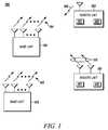
- FIG. 1illustrates a wireless communication network
- FIG. 2illustrates first and second sub-frames having time-frequency resources.
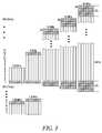
- FIG. 3illustrates sub-frames having different bandwidths.
- FIG. 1illustrates a wireless communication system 100 comprising multiple cell serving base units forming a network distributed over a geographical region.
- a base unitmay also be referred to as an access point, access terminal, Node-B, eNode-B, or by other terminology used in the art.
- the one or more base units 101 and 102serve a number of remote units 103 and 110 within a serving area, for example, a cell, or within a sector thereof.
- the remote unitsmay also be referred to as subscriber units, mobile stations, users, terminals, subscriber stations, user equipment (UE), user terminals, or by other terminology used in the art.
- UEuser equipment
- the base units 101 and 102transmit downlink communication signals 104 and 105 to remote units on at least a portion of the same resources (time and/or frequency).
- Remote units 103 and 110communicate with the one or more serving base units 101 and 102 via uplink communication signals 106 and 113 .
- the one or more base unitsmay comprise one or more transmitters and one or more receivers that serve the remote units.
- the remote unitsmay also comprise one or more transmitters and one or more receivers.
- the communication systemutilizes Orthogonal Frequency Division Multiple Access (OFDMA) or a next generation single-carrier (SC) based Frequency Division Multiple Access (FDMA) architecture for uplink transmissions, such as interleaved FDMA (IFDMA), Localized FDMA (LFDMA), DFT-spread OFDM (DFT-SOFDM) with IFDMA or LFDMA.
- OFDMAInterleaved FDMA
- LFDMALocalized FDMA
- DFT-SOFDMDFT-spread OFDM
- Single-carrier based FDMA approachesare attractive for their improved performance when assessed using contemporary waveform quality metrics, for example, peak-to-average power ratio (PAPR) or the so-called cubic metric (CM). These metrics are good indicators of the power back-off or the power de-rating necessary to maintain linear power amplifier operation.
- lineargenerally refers to a specified and controllable level of distortion both within the signal bandwidth generally occupied by the desired waveform and in neighboring frequencies.
- the architecturemay also include the use of spreading techniques such as direct-sequence CDMA (DS-CDMA), multi-carrier CDMA (MC-CDMA), multi-carrier direct sequence CDMA (MC-DS-CDMA), Orthogonal Frequency and Code Division Multiplexing (OFCDM) with one or two dimensional spreading, or simpler time and frequency division multiplexing/multiple access techniques.
- CDMis used for ACK/NACK information sent in the downlink control region.
- CDMis also used for ACK/NACK and CQI information sent in the uplink control region.
- the network base unitscommunicate with remote units to perform functions such as scheduling the remote units to receive or transmit data using available radio resources.
- the base unitseach include a scheduler for scheduling and allocating resources to the remote units, for example, in corresponding cellular areas.
- schedulingmay be performed in the time and frequency dimensions using a Frequency Selective (FS) scheduler.
- FSFrequency Selective
- each remote unitmay provide a per frequency band channel quality indicator (CQI) to the base unit scheduler to enable FS scheduling.
- CQIper frequency band channel quality indicator
- the channel-coding rate and the modulation schemewhich may be different for different allocation portions of the sub-carrier resources, are also determined by the scheduler and may also depend on the reported CQI or other metric. Selection of the channel-coding rate and modulation scheme is also referred to as link adaptation.
- FIG. 2illustrates first and second sub-frames 202 and 204 that constitute a portion of a radio frame having two or more sub-frames.
- the sub-framesare divided into resource blocks having a specified time dimension and a frequency dimension.
- the sub-frames or regions (e.g. some resource blocks) of a sub-framemay also have a code dimension.
- each sub-frameis divided into multiple time slots, for example, first and second time slots (Slot 1 & Slot 2 ) having equal non-overlapping time intervals in the time domain.
- each framecorresponds to a transmission time interval (TTI).
- TTItransmission time interval
- An exemplary TTIis 1 ms, wherein the TTI is segmented into two sub-frames each having a 0.5 ms temporal length or duration.
- a single TTImay have a length 1 ms or 2 ms.
- a sub-framemight have a 1 ms duration and be composed of two slots of 0.5 ms each wherein each slot is composed of 7 DFT-SOFDM symbols.
- UMTSUniversal Mobile Telecommunications System
- a TTIis defined as a time interval over which a transmission or transport block is transmitted.
- An alternate definition of TTIcould be the length of transmission controlled by a single instance of control channel signaling. More generally, the time duration of the sub-frame and time slots, if any, depends upon the particular implementation, which may depend on a communication protocol.
- the sub-framesare divided into resource blocks also having a specified frequency dimension.
- the resource blocksmay thus be referred to as time-frequency resources.
- the frequency dimension of the sub-framespans a spectrum allocation.
- Each resourcefor example, a control channel resource, includes N frequency resources, for example, frequency sub-carriers.
- FIG. 3illustrates multiple sub-frames having different spectrum allocations, for example, 1.25 MHz, 1.6 MHz, 2.5 MHz, 5 MHz, 10 MHz, 15 MHz and 20 MHz.
- Each sub-frameis divided into multiple resource blocks having a specified bandwidth.
- each sub-framein the time domain, includes 6 symbols, for example, DFT-SOFDM symbols, with long time durations also known as long blocks, which are suitable for data or for control channel information. There are also 2 shorter time duration symbols known as short blocks, which are typically used for pilot symbols, which are also referred to as reference symbols.
- each long blockis composed of 300 sub-carriers and each short block is composed of 150 sub-carriers. In other embodiments, there could be a different number of blocks and each block could be composed of a different number of sub-carriers.
- Each resource blockincludes one or more sub-carriers and can be defined to span 3 long blocks and a short block or it could be defined to span 6 long blocks and 2 short blocks.
- the span of 3 long blocks and a short blockmay be defined to be a slot, as illustrated in FIG. 2 .
- the resource blockscontain 25 sub-carriers for the long blocks and 12 or 13 sub-carriers for the short blocks.
- the control regionis contained in the resource blocks at the band edges RB 1 and RB 12 of each sub-frame.
- the other resource blocks RB 2 - 11are used for data, which may be multiplexed with control information.
- the short blocks or long blocks that do not contain parallel diagonal linessupport data or control information although in the example, as already mentioned, the long blocks containing control information are only in RB 1 and RB 12 .
- only the short blockshave the parallel diagonal lines, which indicate that only short blocks are used as pilots.
- pilotscould also be on long blocks and data could also be on short blocks.
- the two short pilot blockscould be replaced by a single long pilot block.
- the scheduling entityallocates time-frequency radio resources in a sub-frame to wireless communication devices, for example, to the remote units 103 and 110 in FIG. 1 .
- the schedulerassigns resource blocks to different remote units, for example, UE 1 , UE 2 , etc.
- the time-frequency radio resourcesinclude a set of control channel resources extending contiguously from at least one edge of the spectrum allocation toward a medial portion of the spectrum allocation, wherein at least the medial portion of the spectrum allocation includes non-control channel resources, for example, data blocks.
- the time-frequency radio resourcesinclude a set of control channel resources extending from first and second opposite edges of the spectrum allocation toward the medial portion of the spectrum allocation.
- the control channel resourcescomprise one or more sub-carriers, which may constitute a resource block.
- the data blocks in the medial portion of the spectrum allocationmay include control information, for example, by multiplexing the data and control information.
- control informationcan be sent “in-band” or “out-of-band” in a primarily uplink data transmission.
- the data and control informationare coded together, for example, during DFT-SOFDM waveform generation before a DFT pre-coder.
- the control informationis “out-of-band”
- the control informationis “piggy-backed” by puncturing a coded data block.
- the first resource block “ 1 ” in the time domain of each sub-frameis dedicated to control channel resources (Ctl).
- the resource block “ 1 ” extending from one edge of the spectrum allocationis dedicated to control channel resources.
- resource blocks “ 1 ” and “ 12 ” extending from opposite edges of the spectrum allocationare dedicated to control channel resources.
- resource blocks “ 1 ” and “ 2 ” on one side of the spectrum allocation and resource blocks “ 23 ” and “ 24 ” on the opposite side of the spectrum allocationare dedicated to control channel resources.
- the control channel resource blocks extending from one or more edges of the spectrum allocationprovide a guard band effect.
- the schedulerallocates a control channel resource within a contiguous set of control channel resources extending from the not more than one edge of the spectrum allocation to a particular wireless communication device for a full duration of the sub-frame.
- uplink (UL) control channel resources located in the first resource block (RB 1 ) extending from one edge of the spectrum allocationare assigned to UE 1 for the full duration of the sub-frame.
- the uplink (UL) control channel resourcescomprise two 15 kHz sub-carriers in each of the 6 long blocks for data and a 30 kHz sub-carrier in each of the two short blocks for the pilot channel.
- Control channel resourcesare also allocated as UL control channel resources to remote units (UE 2 -UE 12 ) for the duration of the sub-frame.
- resources extending contiguously from an opposite edge of the spectrum allocation in the second sub-frame 204are allocated as UL control channel resources to other remote units (UE 13 -UE 25 ) for the duration of the sub-frame.
- UL control channel resourcesmay comprise two 15 kHz sub-carriers in each of the 6 long blocks for data and a 30 kHz sub-carrier in each of the two short blocks for the pilot channel.
- the schedulerallocates first and second control channel resources within contiguous sets of control channel resources extending from corresponding first and second opposite edges of the sub-frame spectrum allocation, wherein the first and second control channel resource allocations do not overlap in time.
- Such an allocationprovides frequency diversity.
- at least the medial portion of the spectrum allocationincludes non-control channel resources, for example, data blocks.
- the data blocks in the medial portion of the spectrum allocationalso include control information.
- the contiguous sets of control channel resources extending from corresponding first and second opposite edges of the sub-frame spectrum allocationsalso have a code dimension.
- the first sub-frame 202is divided into first and second slots (Slot 1 & Slot 2 ) of 0.25 ms duration each.
- UE 2is only allocated resources in RB 1 in the time duration spanning 3 long blocks and a single short block (in Slot 1 ).
- UE 2is not allocated resources in RB 1 in Slot 2 .
- UE 2is allocated resources in RB 12 .
- UE 2is only allocated resources in Slot 1 in RB 1 and resources in Slot 2 in RB 12 thus providing frequency diversity while preserving the single carrier waveform.
- each sub-framesupports allocating control information to 12 UEs, provided that only a single RB slot at one edge of the carrier band and a single RB slot in the second half of the RB at the other edge of the carrier band are allocated to each UE.
- RB 1 in Slot 2 and RB 12 in Slot 1could also be used for data in the event that these resource blocks are not required to allocate control information to other UEs.
- the control resource(a slot of RB 1 or RB 12 ) has a code dimension such that each control allocation corresponds to one of M orthogonal codes. Each orthogonal code spans the time and frequency components of the control resource. Given not more than M UEs are each assigned a different orthogonal code then each UE can simultaneously transmit its control information using the assigned control resource.
- slot 1two 15 kHz sub-carriers in each of the 6 long blocks for data and a 30 kHz sub-carrier in each of 2 short blocks for pilot located in the first resource block (RB 1 ) extending contiguously from the first edge of the spectrum allocation are allocated to UE 1 .
- the slotsare 0.5 ms in duration.
- Slot 2two 15 kHz sub-carriers in each of the 6 long blocks for data and a 30 kHz sub-carrier in each of 2 short blocks for the pilot channel located in the last resource block (RB 12 ) extending contiguously from the second, opposite edge of the spectrum allocation of the second slot are also allocated to UE 1 .
- Other remote unitsare also allocated frequency diverse control channel resources in the first sub-frame 202 .
- control channel resources spanning 15 kHz sub-carriers 3 and 4 of the data long blocks and a 30 kHz sub-carrier for the pilot short block in the first resource block (RB 1 ) extending contiguously from the first edge of the spectrum allocationare allocated to UE 2
- control channel resources spanning 15 kHz sub-carriers 4 and 5 of the data long blocks and a 30 kHz sub-carrier for the pilot short block in the first resource block (RB 12 ) extending contiguously from the second, opposite edge of the spectrum allocation of the second slotare also allocated to UE 2 .
- the medial portion of spectrum allocationsis used primarily for data resource allocation, although medial portions of the allocation could also be used for control channel resource allocation as discussed.
- Allocation of control channels with their small occupied bandwidth to carrier band edge resource blocksreduces out of carrier band emissions cause by data resource allocations on inner band resource blocks.
- Allocation of control channels with their small occupied bandwidth to carrier band edge resource blocksalso maximizes the frequency diversity benefit for frequency diverse control channel allocations.
- control signalingfor example, data-associated and data-non-associated signaling
- control signalingfor example, data-associated and data-non-associated signaling
- out of carrier band emissions from data resource allocations on inner band resource blocksare reduced and the frequency diversity benefit of frequency diverse control signalling allocations may be increased.
- Thismay also increase data transmission rates since control in the medial portion of the spectrum allocation restricts allocated data resources to be either above or below the control region (or between control regions) to maintain single carrier nature of uplink waveform.
- Segregating UE's by channel quality and mapping them to different sub-frameshelps minimize a received signal dynamic range at the Node-B receiver and thereby minimizes required power control dynamic range and improves signaling reception by increasing Es/Ne where Ne is interference from adjacent out of channel emissions.
Landscapes
- Engineering & Computer Science (AREA)
- Signal Processing (AREA)
- Computer Networks & Wireless Communication (AREA)
- Mobile Radio Communication Systems (AREA)
Abstract
Description
Claims (24)
Priority Applications (1)
| Application Number | Priority Date | Filing Date | Title |
|---|---|---|---|
| US11/682,947US7873010B2 (en) | 2007-03-07 | 2007-03-07 | Control signaling resource assignment in wireless communication networks |
Applications Claiming Priority (1)
| Application Number | Priority Date | Filing Date | Title |
|---|---|---|---|
| US11/682,947US7873010B2 (en) | 2007-03-07 | 2007-03-07 | Control signaling resource assignment in wireless communication networks |
Publications (2)
| Publication Number | Publication Date |
|---|---|
| US20080219236A1 US20080219236A1 (en) | 2008-09-11 |
| US7873010B2true US7873010B2 (en) | 2011-01-18 |
Family
ID=39741524
Family Applications (1)
| Application Number | Title | Priority Date | Filing Date |
|---|---|---|---|
| US11/682,947Active2029-01-15US7873010B2 (en) | 2007-03-07 | 2007-03-07 | Control signaling resource assignment in wireless communication networks |
Country Status (1)
| Country | Link |
|---|---|
| US (1) | US7873010B2 (en) |
Cited By (7)
| Publication number | Priority date | Publication date | Assignee | Title |
|---|---|---|---|---|
| US20090296681A1 (en)* | 2008-05-30 | 2009-12-03 | Nokia Corporation | Use of out-of-band signaling for wireless communication network to enhance search and entry |
| US20100067593A1 (en)* | 2008-09-16 | 2010-03-18 | Futurewei Technologies, Inc. | Method and Apparatus for Transmitting and Receiving Control Information in a Wireless Communication System |
| US20100182972A1 (en)* | 2009-01-21 | 2010-07-22 | Hitachi, Ltd. | Wireless communication system, mobile station , and base station |
| US20100260164A1 (en)* | 2007-12-20 | 2010-10-14 | Seong Ho Moon | Method for transmitting data in wireless communication system |
| US20110069672A1 (en)* | 2008-05-29 | 2011-03-24 | Hyun Woo Lee | Method for uplink transmission of control information in mobile communication system |
| US20130176994A1 (en)* | 2001-05-04 | 2013-07-11 | Ipr Licensing, Inc. | Coded reverse link messages for closed-loop power control of forward link control messages |
| US10419176B2 (en) | 2015-11-12 | 2019-09-17 | Qualcomm Incorporated | Methods and apparatus for transmitting in-band control information in wireless communication |
Families Citing this family (31)
| Publication number | Priority date | Publication date | Assignee | Title |
|---|---|---|---|---|
| US8451915B2 (en)* | 2007-03-21 | 2013-05-28 | Samsung Electronics Co., Ltd. | Efficient uplink feedback in a wireless communication system |
| US7944981B2 (en)* | 2007-05-31 | 2011-05-17 | Motorola Mobility, Inc. | Data transmission in a frequency division multiple access communication system |
| JP4659804B2 (en)* | 2007-10-01 | 2011-03-30 | 株式会社エヌ・ティ・ティ・ドコモ | User apparatus, transmission method, and communication system |
| EP3432504B1 (en)* | 2007-10-30 | 2021-06-23 | Nokia Technologies Oy | Methods, apparatuses, system and related computer program product for resource allocation |
| DE102008011122A1 (en)* | 2008-02-26 | 2009-09-03 | Rohde & Schwarz Gmbh & Co. Kg | Method and system for bandwidth detection |
| JP5011161B2 (en)* | 2008-02-29 | 2012-08-29 | 京セラ株式会社 | Base station equipment |
| US9106378B2 (en) | 2009-06-10 | 2015-08-11 | Qualcomm Incorporated | Systems, apparatus and methods for communicating downlink information |
| US9144037B2 (en) | 2009-08-11 | 2015-09-22 | Qualcomm Incorporated | Interference mitigation by puncturing transmission of interfering cells |
| US9277566B2 (en)* | 2009-09-14 | 2016-03-01 | Qualcomm Incorporated | Cross-subframe control channel design |
| US8942192B2 (en) | 2009-09-15 | 2015-01-27 | Qualcomm Incorporated | Methods and apparatus for subframe interlacing in heterogeneous networks |
| US8514796B2 (en) | 2010-04-01 | 2013-08-20 | Sharp Laboratories Of America, Inc. | Transmitting control data and user data on a physical uplink channel |
| US9271167B2 (en) | 2010-04-13 | 2016-02-23 | Qualcomm Incorporated | Determination of radio link failure with enhanced interference coordination and cancellation |
| US9226288B2 (en) | 2010-04-13 | 2015-12-29 | Qualcomm Incorporated | Method and apparatus for supporting communications in a heterogeneous network |
| US9125072B2 (en) | 2010-04-13 | 2015-09-01 | Qualcomm Incorporated | Heterogeneous network (HetNet) user equipment (UE) radio resource management (RRM) measurements |
| US9392608B2 (en) | 2010-04-13 | 2016-07-12 | Qualcomm Incorporated | Resource partitioning information for enhanced interference coordination |
| KR101760016B1 (en)* | 2010-12-21 | 2017-07-21 | 한국전자통신연구원 | Voltage control oscillator and method for oscillating voltage control |
| GB2487909B8 (en) | 2011-02-04 | 2015-01-21 | Sca Ipla Holdings Inc | Telecommunications method and system |
| US9258250B2 (en)* | 2011-04-14 | 2016-02-09 | Qualcomm Incorporated | Dynamic data channel scheduling |
| TR201906406T4 (en)* | 2011-05-03 | 2019-05-21 | Ericsson Telefon Ab L M | Monitoring the control channel on the basis of search area. |
| US9647863B2 (en) | 2012-02-27 | 2017-05-09 | Intel Corporation | Techniques to manage dwell times for pilot rotation |
| KR20140032705A (en)* | 2012-09-07 | 2014-03-17 | 삼성전자주식회사 | Method and apparatus for transmitting a uplink in inter-enb and inter-duplex carrier aggregation system |
| FR2997253B1 (en)* | 2012-10-24 | 2014-10-31 | Thales Sa | METHOD FOR DYNAMIC ALLOCATION OF SHARED RESOURCES IN A TIME-FREQUENCY PLAN AND ASSOCIATED DEVICE |
| EP2962485B1 (en)* | 2013-03-01 | 2019-08-21 | Intel IP Corporation | Wireless local area network (wlan) traffic offloading |
| US10075949B2 (en) | 2016-02-02 | 2018-09-11 | Motorola Mobility Llc | Method and apparatus for low latency transmissions |
| US11589347B2 (en) | 2015-11-06 | 2023-02-21 | Motorola Mobility Llc | Method and apparatus for low latency transmissions |
| US9801175B2 (en) | 2015-11-06 | 2017-10-24 | Motorola Mobility Llc | Method and apparatus for low latency transmissions |
| US10708728B2 (en)* | 2016-09-23 | 2020-07-07 | Qualcomm Incorporated | Adaptive modulation order for multi-user superposition transmissions with non-aligned resources |
| US11032032B2 (en)* | 2017-11-28 | 2021-06-08 | Qualcomm Incorporated | Sub-band configuration for preemption indication to eMBB UEs |
| CN111726761B (en)* | 2020-07-23 | 2021-11-16 | 拉扎斯网络科技(上海)有限公司 | Internet of things data transmission method and device |
| US12166702B2 (en)* | 2021-09-24 | 2024-12-10 | Qualcomm Incorporated | Phase tracking reference signal pilot allocation sizes |
| US12341643B2 (en)* | 2021-10-18 | 2025-06-24 | Qualcomm Incorporated | Control and data channel processing for higher bands |
Citations (6)
| Publication number | Priority date | Publication date | Assignee | Title |
|---|---|---|---|---|
| US6385434B1 (en)* | 1998-09-16 | 2002-05-07 | Motorola, Inc. | Wireless access unit utilizing adaptive spectrum exploitation |
| US20020118666A1 (en)* | 2000-11-15 | 2002-08-29 | Stanwood Kenneth L. | Framing for an adaptive modulation communication system |
| US20020119781A1 (en)* | 2000-12-15 | 2002-08-29 | Xiaodong Li | OFDMA with adaptive subcarrier-cluster configuration and selective loading |
| US6522636B1 (en)* | 1999-10-01 | 2003-02-18 | Motorola, Inc. | Satellite communications system and method with real-time power-based flow control |
| US6567416B1 (en)* | 1997-10-14 | 2003-05-20 | Lucent Technologies Inc. | Method for access control in a multiple access system for communications networks |
| US6741554B2 (en)* | 2002-08-16 | 2004-05-25 | Motorola Inc. | Method and apparatus for reliably communicating information packets in a wireless communication network |
- 2007
- 2007-03-07USUS11/682,947patent/US7873010B2/enactiveActive
Patent Citations (6)
| Publication number | Priority date | Publication date | Assignee | Title |
|---|---|---|---|---|
| US6567416B1 (en)* | 1997-10-14 | 2003-05-20 | Lucent Technologies Inc. | Method for access control in a multiple access system for communications networks |
| US6385434B1 (en)* | 1998-09-16 | 2002-05-07 | Motorola, Inc. | Wireless access unit utilizing adaptive spectrum exploitation |
| US6522636B1 (en)* | 1999-10-01 | 2003-02-18 | Motorola, Inc. | Satellite communications system and method with real-time power-based flow control |
| US20020118666A1 (en)* | 2000-11-15 | 2002-08-29 | Stanwood Kenneth L. | Framing for an adaptive modulation communication system |
| US20020119781A1 (en)* | 2000-12-15 | 2002-08-29 | Xiaodong Li | OFDMA with adaptive subcarrier-cluster configuration and selective loading |
| US6741554B2 (en)* | 2002-08-16 | 2004-05-25 | Motorola Inc. | Method and apparatus for reliably communicating information packets in a wireless communication network |
Non-Patent Citations (3)
| Title |
|---|
| Ericsson; "Summary of E-Mail Discussions on Control Signaling"; TSG-RAN WG1 #46BIS; R1-062874; Seoul, Korea; Oct. 9-13, 2006; 2 Pages. |
| R1-060882, TSG-RAN WG1 #44bis, "E-UTRA Uplink Control Signaling +TP", Motorola, Athens, Greece, Mar. 26-31, 2006, all pages. |
| Samsung; "Data and Control Multiplexing in DFT-S-OFDM"; 3GPP TSG RAN WG1 Meeting #42BIS; R1-051039; San Diego, USA; Oct. 10-14, 2005; 5 Pages. |
Cited By (14)
| Publication number | Priority date | Publication date | Assignee | Title |
|---|---|---|---|---|
| US20130176994A1 (en)* | 2001-05-04 | 2013-07-11 | Ipr Licensing, Inc. | Coded reverse link messages for closed-loop power control of forward link control messages |
| US20150257097A1 (en)* | 2001-05-04 | 2015-09-10 | Ipr Licensing, Inc. | Coded reverse link messages for closed-loop power control of forward link control messages |
| US9019930B2 (en) | 2001-05-04 | 2015-04-28 | Ipr Licensing, Inc. | Coded reverse link messages for closed-loop power control of forward link control messages |
| US8737343B2 (en)* | 2001-05-04 | 2014-05-27 | Ipr Licensing, Inc. | Coded reverse link messages for closed-loop power control of forward link control messages |
| US20100260164A1 (en)* | 2007-12-20 | 2010-10-14 | Seong Ho Moon | Method for transmitting data in wireless communication system |
| US8396068B2 (en)* | 2007-12-20 | 2013-03-12 | Lg Electronics Inc. | Method for transmitting data in wireless communication system |
| US8446873B2 (en)* | 2008-05-29 | 2013-05-21 | Lg Electronics Inc. | Method for uplink transmission of control information in mobile communication system |
| US20110069672A1 (en)* | 2008-05-29 | 2011-03-24 | Hyun Woo Lee | Method for uplink transmission of control information in mobile communication system |
| US8081601B2 (en)* | 2008-05-30 | 2011-12-20 | Nokia Corporation | Use of out-of-band signaling for wireless communication network to enhance search and entry |
| US20090296681A1 (en)* | 2008-05-30 | 2009-12-03 | Nokia Corporation | Use of out-of-band signaling for wireless communication network to enhance search and entry |
| US8155222B2 (en)* | 2008-09-16 | 2012-04-10 | Futurewei Technologies, Inc. | Method and apparatus for transmitting and receiving control information in a wireless communication system |
| US20100067593A1 (en)* | 2008-09-16 | 2010-03-18 | Futurewei Technologies, Inc. | Method and Apparatus for Transmitting and Receiving Control Information in a Wireless Communication System |
| US20100182972A1 (en)* | 2009-01-21 | 2010-07-22 | Hitachi, Ltd. | Wireless communication system, mobile station , and base station |
| US10419176B2 (en) | 2015-11-12 | 2019-09-17 | Qualcomm Incorporated | Methods and apparatus for transmitting in-band control information in wireless communication |
Also Published As
| Publication number | Publication date |
|---|---|
| US20080219236A1 (en) | 2008-09-11 |
Similar Documents
| Publication | Publication Date | Title |
|---|---|---|
| US7873010B2 (en) | Control signaling resource assignment in wireless communication networks | |
| JP7515921B2 (en) | Method, device and system for resource allocation in a wireless communication system - Patents.com | |
| RU2689127C2 (en) | Downlink control channel signalling in wireless communication systems | |
| KR101789345B1 (en) | Apparatus and method for enhancing features of uplink refernece signals | |
| EP1985041B1 (en) | Apparatus and method for allocating resources and performing communication in a wireless communication system | |
| US8982752B2 (en) | Base station apparatus and user terminal | |
| US9252933B2 (en) | Resource allocation including a DC sub-carrier in a wireless communication system | |
| EP2498516B1 (en) | Radio communication base station device and control channel arrangement method | |
| WO2016070838A1 (en) | Methods and apparatus for resource allocation | |
| US9137803B2 (en) | Radio communication control method, base station apparatus and mobile terminal apparatus | |
| EP3313005A1 (en) | Method and apparatus for transmitting and receiving time division duplex frame configuration information in wireless communication system | |
| US8787281B2 (en) | Base station apparatus and user terminal | |
| US20130182673A1 (en) | Base station apparatus, mobile terminal apparatus and communication control method | |
| JP5856191B2 (en) | Apparatus and method for improving the characteristics of uplink reference signals | |
| KR20080097112A (en) | How to send control area format information |
Legal Events
| Date | Code | Title | Description |
|---|---|---|---|
| AS | Assignment | Owner name:MOTOROLA INC, ILLINOIS Free format text:ASSIGNMENT OF ASSIGNORS INTEREST;ASSIGNORS:LOVE, ROBERT T.;SCHWENT, DALE G.;WILSON, DAVID R.;REEL/FRAME:018973/0241 Effective date:20070306 | |
| AS | Assignment | Owner name:MOTOROLA MOBILITY, INC, ILLINOIS Free format text:ASSIGNMENT OF ASSIGNORS INTEREST;ASSIGNOR:MOTOROLA, INC;REEL/FRAME:025673/0558 Effective date:20100731 | |
| STCF | Information on status: patent grant | Free format text:PATENTED CASE | |
| AS | Assignment | Owner name:MOTOROLA MOBILITY LLC, ILLINOIS Free format text:CHANGE OF NAME;ASSIGNOR:MOTOROLA MOBILITY, INC.;REEL/FRAME:029216/0282 Effective date:20120622 | |
| FPAY | Fee payment | Year of fee payment:4 | |
| AS | Assignment | Owner name:GOOGLE TECHNOLOGY HOLDINGS LLC, CALIFORNIA Free format text:ASSIGNMENT OF ASSIGNORS INTEREST;ASSIGNOR:MOTOROLA MOBILITY LLC;REEL/FRAME:034451/0001 Effective date:20141028 | |
| MAFP | Maintenance fee payment | Free format text:PAYMENT OF MAINTENANCE FEE, 8TH YEAR, LARGE ENTITY (ORIGINAL EVENT CODE: M1552) Year of fee payment:8 | |
| MAFP | Maintenance fee payment | Free format text:PAYMENT OF MAINTENANCE FEE, 12TH YEAR, LARGE ENTITY (ORIGINAL EVENT CODE: M1553); ENTITY STATUS OF PATENT OWNER: LARGE ENTITY Year of fee payment:12 |