US7872833B2 - Head with a transducer overcoat having a trailing air flow dam that is shallowly recessed from an air bearing surface - Google Patents
Head with a transducer overcoat having a trailing air flow dam that is shallowly recessed from an air bearing surfaceDownload PDFInfo
- Publication number
- US7872833B2 US7872833B2US11/860,667US86066707AUS7872833B2US 7872833 B2US7872833 B2US 7872833B2US 86066707 AUS86066707 AUS 86066707AUS 7872833 B2US7872833 B2US 7872833B2
- Authority
- US
- United States
- Prior art keywords
- trailing
- head
- transducer
- air bearing
- slider
- Prior art date
- Legal status (The legal status is an assumption and is not a legal conclusion. Google has not performed a legal analysis and makes no representation as to the accuracy of the status listed.)
- Active, expires
Links
- 238000011144upstream manufacturingMethods0.000claimsabstractdescription40
- 239000000463materialSubstances0.000claimsdescription12
- PNEYBMLMFCGWSK-UHFFFAOYSA-Naluminium oxideInorganic materials[O-2].[O-2].[O-2].[Al+3].[Al+3]PNEYBMLMFCGWSK-UHFFFAOYSA-N0.000claimsdescription11
- 239000000758substrateSubstances0.000claimsdescription5
- VYPSYNLAJGMNEJ-UHFFFAOYSA-NSilicium dioxideChemical compoundO=[Si]=OVYPSYNLAJGMNEJ-UHFFFAOYSA-N0.000claimsdescription4
- 229910052681coesiteInorganic materials0.000claimsdescription2
- 229910052593corundumInorganic materials0.000claimsdescription2
- 229910052906cristobaliteInorganic materials0.000claimsdescription2
- 239000000377silicon dioxideSubstances0.000claimsdescription2
- 229910052682stishoviteInorganic materials0.000claimsdescription2
- 229910052905tridymiteInorganic materials0.000claimsdescription2
- 229910001845yogo sapphireInorganic materials0.000claimsdescription2
- 239000000314lubricantSubstances0.000description9
- 238000009825accumulationMethods0.000description6
- 238000004519manufacturing processMethods0.000description6
- MTPVUVINMAGMJL-UHFFFAOYSA-Ntrimethyl(1,1,2,2,2-pentafluoroethyl)silaneChemical compoundC[Si](C)(C)C(F)(F)C(F)(F)FMTPVUVINMAGMJL-UHFFFAOYSA-N0.000description6
- 238000005530etchingMethods0.000description5
- 230000035945sensitivityEffects0.000description4
- 230000000873masking effectEffects0.000description3
- 230000002411adverseEffects0.000description2
- 239000000919ceramicSubstances0.000description2
- 238000011109contaminationMethods0.000description2
- 230000001939inductive effectEffects0.000description2
- 230000003287optical effectEffects0.000description2
- 230000009467reductionEffects0.000description2
- 238000009987spinningMethods0.000description2
- 238000000992sputter etchingMethods0.000description2
- 229910010293ceramic materialInorganic materials0.000description1
- 230000005672electromagnetic fieldEffects0.000description1
- 230000002452interceptive effectEffects0.000description1
- 230000035939shockEffects0.000description1
- 229910052710siliconInorganic materials0.000description1
- 239000010703siliconSubstances0.000description1
- 239000010409thin filmSubstances0.000description1
- 230000005641tunnelingEffects0.000description1
Images


Classifications
- G—PHYSICS
- G11—INFORMATION STORAGE
- G11B—INFORMATION STORAGE BASED ON RELATIVE MOVEMENT BETWEEN RECORD CARRIER AND TRANSDUCER
- G11B5/00—Recording by magnetisation or demagnetisation of a record carrier; Reproducing by magnetic means; Record carriers therefor
- G11B5/48—Disposition or mounting of heads or head supports relative to record carriers ; arrangements of heads, e.g. for scanning the record carrier to increase the relative speed
- G11B5/58—Disposition or mounting of heads or head supports relative to record carriers ; arrangements of heads, e.g. for scanning the record carrier to increase the relative speed with provision for moving the head for the purpose of maintaining alignment of the head relative to the record carrier during transducing operation, e.g. to compensate for surface irregularities of the latter or for track following
- G11B5/60—Fluid-dynamic spacing of heads from record-carriers
- G11B5/6005—Specially adapted for spacing from a rotating disc using a fluid cushion
- G11B5/6082—Design of the air bearing surface
- G—PHYSICS
- G11—INFORMATION STORAGE
- G11B—INFORMATION STORAGE BASED ON RELATIVE MOVEMENT BETWEEN RECORD CARRIER AND TRANSDUCER
- G11B5/00—Recording by magnetisation or demagnetisation of a record carrier; Reproducing by magnetic means; Record carriers therefor
- G11B5/48—Disposition or mounting of heads or head supports relative to record carriers ; arrangements of heads, e.g. for scanning the record carrier to increase the relative speed
- G11B5/58—Disposition or mounting of heads or head supports relative to record carriers ; arrangements of heads, e.g. for scanning the record carrier to increase the relative speed with provision for moving the head for the purpose of maintaining alignment of the head relative to the record carrier during transducing operation, e.g. to compensate for surface irregularities of the latter or for track following
- G11B5/60—Fluid-dynamic spacing of heads from record-carriers
- G11B5/6005—Specially adapted for spacing from a rotating disc using a fluid cushion
Definitions
- the present inventionrelates generally to the field of information storage devices, and more particularly to air bearing sliders used in such devices.
- Information storage devicesare used to retrieve and/or store data in computers and other consumer electronics devices.
- a magnetic hard disk driveis an example of an information storage device that includes one or more heads that can both read and write, but other information storage devices also include heads—sometimes including heads that cannot write.
- the typical hard disk driveincludes a head disk assembly (HDA) and a printed circuit board (PCB) attached to a disk drive base of the HDA.
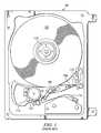
- the head disk assembly 100includes at least one disk 102 (such as a magnetic disk, magneto-optical disk, or optical disk), a spindle motor 104 for rotating the disk, and a head stack assembly (HSA) 106 .
- the spindle motortypically includes a rotating hub on which disks are mounted and clamped, a magnet attached to the hub, and a stator. Various coils of the stator are selectively energized to form an electromagnetic field that pulls/pushes on the magnet, thereby rotating the hub.
- the printed circuit board assemblyincludes electronics and firmware for controlling the rotation of the spindle motor and for controlling the position of the HSA, and for providing a data transfer channel between the disk drive and its host.
- the head stack assembly 106typically includes an actuator, at least one head gimbal assembly (HGA) 108 that includes a head, and a flex cable assembly 110 .
- HGAhead gimbal assembly
- the actuatorDuring operation of the disk drive, the actuator must rotate to position the heads adjacent desired information tracks on the disk.
- the actuatorincludes a pivot bearing cartridge 112 to facilitate such rotational positioning.
- One or more actuator armsextend from the actuator body.
- An actuator coil 114is supported by the actuator body opposite the actuator arms.
- the actuator coilis configured to interact with one or more fixed magnets in the HDA, typically a pair, to form a voice coil motor.
- the printed circuit board assemblyprovides and controls an electrical current that passes through the actuator coil and results in a torque being applied to the actuator.
- a crash stopis typically provided to limit rotation of the actuator in a given direction, and a latch is typically provided to prevent rotation of the actuator when the disk drive is not in use.
- the headtypically comprises a body called a “slider” that carries a magnetic transducer on its trailing end.
- the magnetic transducertypically comprises a writer and a read element.
- the magnetic transducer's writermay be of a longitudinal or perpendicular design, and the read element of the magnetic transducer may be inductive or magnetoresistive.
- the transduceris typically supported in very close proximity to the magnetic disk by a hydrodynamic air bearing. As the motor rotates the magnetic disk, the hydrodynamic air bearing is formed between an air bearing surface of the slider of the head, and a surface of the magnetic disk. The thickness of the air bearing at the location of the transducer is commonly referred to as “flying height.”
- Magnetic hard disk drivesare not the only type of information storage devices that have utilized air bearing sliders.
- air bearing slidershave also been used in optical information storage devices to position a mirror and an objective lens for focusing laser light on the surface of disk media that is not necessarily magnetic.
- the flying heightis a key parameter that affects the performance of an information storage device. Accordingly, the nominal flying height is typically chosen as a careful compromise between each extreme in a classic engineering “trade-off.” If the flying height is too high, the ability of the transducer to write and/or read information to/from the disk surface is degraded. Therefore, reductions in flying height can facilitate desirable increases in the areal density of data stored on a disk surface. However, the air bearing between the slider and the disk surface can not be eliminated entirely because the air bearing serves to reduce friction and wear (between the slider and the disk surface) to an acceptable level. Excessive reduction in the nominal flying height degrades the tribological performance of the disk drive to the point where the disk drive's lifetime and reliability become unacceptable.
- the headincludes a transducer and a slider having a leading face, a trailing face, and an air bearing surface.
- the sliderhas an overcoat layer that includes the trailing face and that overcoats the transducer.
- the air bearing surfacedefines an upstream direction pointing from the trailing face to the leading face.
- the air bearing surfaceincludes a trailing pad having a major surface adjacent the transducer, with the major surface lying in a primary plane.
- the air bearing surfacealso includes a sub-ambient pressure cavity disposed upstream of the overcoat layer and being recessed from the primary plane by a cavity depth in the range 0.8 to 2 microns.
- the overcoat layerincludes a trailing air flow dam being recessed from the primary plane by a step depth in the range 0.05 to 0.5 microns.
- the overcoat layeralso includes a corner region recessed from the primary plane by at least the cavity depth.
- FIG. 1depicts a contemporary hard disk drive information storage device.
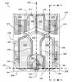
- FIG. 2is an air bearing surface view of a head according to an exemplary embodiment of the present invention (not necessarily to scale).
- FIG. 3is cross-sectional view of the head shown in FIG. 2 , taken along the plane of cross-section designated as A-A in FIG. 2 .
- A-Athe plane of cross-section designated as A-A in FIG. 2 .
- the step heightsare not to scale but rather are exaggerated so as to be easily discernible.
- FIG. 4is an air bearing surface view of a head according to another exemplary embodiment of the present invention (not necessarily to scale).
- FIG. 5is cross-sectional view of the head shown in FIG. 4 , taken along the plane of cross-section designated as B-B in FIG. 4 .
- B-Bthe plane of cross-section designated as B-B in FIG. 4 .
- the step heightsare not to scale but rather are exaggerated so as to be easily discernible.
- FIG. 6is an air bearing surface view of a head according to another exemplary embodiment of the present invention (not necessarily to scale).
- FIG. 7is cross-sectional view of the head shown in FIG. 6 , taken along the plane of cross-section designated as C-C in FIG. 6 .
- C-Ccross-section
- head 200comprises a transducer 202 for at least reading information from the disk.
- the transducer 202is a merged thin film magnetic transducer comprising an inductive writer and magneto resistive read element.
- the magneto resistive elementmay be a giant magneto resistive element (GMR) or tunneling magneto resistive element (TMR).
- the writermay be a perpendicular magnetic recording (PMR) writer.
- Head 200also comprises a slider 204 , which is typically fabricated from a ceramic material such as alumina titanium carbide.
- Slider 204includes an air bearing surface 206 , which may be formed on the surface of slider 204 by etching or ion milling and has a geometry that may be defined by use of a mask.
- the slider 204has an overcoat layer 236 that includes a trailing face 208 and includes a transducer region 203 that overcoats the transducer 202 .
- the slider 204also includes a leading face 210 .
- the air bearing surface 206includes deep cavities 216 and 218 , and shallow cavities 220 and 222 .
- the shallow cavities 220 and 222can develop a sub-ambient pressure region between the air bearing surface 206 and the surface of an adjacent disk.
- the sub-ambient pressuremay serve to reduce flying height sensitivities to changes in altitude and air bearing geometries.
- the air bearing surface 206also includes two leading pads 212 and 214 that are adjacent to and upstream of the deep cavities 216 and 218 , respectively.
- upstreamis used herein only to define a directional convention to facilitate description of relative positions on the air bearing surface 206 , and does not require the presence or existence of any stream.
- upstreamcan be understood to refer to a range of directions across the air bearing surface 206 that generally point away from the trailing face 208 and towards the leading face 210 .
- upstream directionswould ultimately be generally opposite the motion of an adjacent rotating disk surface.
- An upstream directionwould be a direction within the aforementioned range.
- downstreamis used herein as an antonym of “upstream.”
- the air bearing surface 206defines a lateral axis that is perpendicular to that upstream direction.
- the air bearing surfacedefines a corresponding lateral axis 232 that is parallel to the leading face 210 or the trailing face 208 (i.e. orthogonal to that upstream direction).
- the slider widthcan be measured along lateral axis 232 .
- non-zero skew upstream directionsare also contemplated herein.
- the two leading pads 212 , 214may be separated by shallow cavities 220 and 222 , respectively, and shallow cavities 220 and 222 may themselves be separated by a longitudinal divider 217 .
- the leading pads 212 and 214each include a major surface that is not recessed and instead establishes an air bearing surface datum plane (hereinafter referred to as the primary plane) 300 , from which the recession of other surfaces that are approximately parallel to the primary plane 300 may be measured.
- the leading pads 212 and 214can develop a super-ambient pressure region between the air bearing surface 206 and the surface of an adjacent disk, causing the slider to assume a positive pitch attitude.
- Deep cavities 216 and 218each include a surface in a plane 330 that is recessed from the primary plane 300 by a deep cavity recession depth 370 .
- the deep cavity recession depthis preferably but not necessarily in the range 3 microns to 4 microns.
- Shallow cavities 220 and 222each include a surface in an intermediate plane 320 that lies between the primary plane 300 and the deep cavity plane 330 , and that is recessed from the primary plane 300 by a shallow cavity recession depth 360 .
- the shallow cavity recession depth 360is preferably in the range 0.8 microns to 2 microns.
- leading pads 212 and 214are connected by a leading dam 276 that helps prevent particulate contamination from entering the air bearing, and that assists in creating sub-ambient pressure in shallow cavities 220 and 222 .
- the leading pads 212 and 214also include leading pressurizing steps 224 and 226 , respectively.
- the leading pressurizing steps 224 and 226each include a surface in a plane 310 that lies between the primary plane 300 and the intermediate plane 320 .
- the plane 310is recessed from the primary plane 300 by a pressurizing step recession depth 350 .
- the leading pressurizing steps 224 and 226can help develop super-ambient pressure between the leading pads 212 and 214 , respectively and the surface of an adjacent disk.
- the pressurizing step recession depth 350is preferably in the range 0.05 microns to 0.5 microns. In certain embodiments, fabrication of the air bearing surface can be simplified if the deep cavity recession depth 370 is equal to the sum of the shallow cavity recession depth 360 and the pressurizing step recession depth 350 .
- the air bearing surface 206includes mid-cavity dams 272 and 274 that are disposed upstream of a central cavity 228 .
- Mid-cavity dam 272includes a surface in the plane 320
- mid-cavity dam 274includes a surface in the plane 310 .
- mid-cavity dam 272is oriented to confront the skewed incoming air flow when the head is near the inner diameter of the disk
- mid-cavity dam 274is oriented to confront the differently-skewed incoming air flow when the head is near the outer diameter of the disk.
- mid-cavity dam 272is recessed from the primary plane 300 more than mid-cavity dam 274 is, mid-cavity dam 272 tends to allow airflow into central cavity 228 more easily than mid-cavity dam 274 does.
- This difference in recessioncan be used by the air bearing designer to desensitize the flying height to changes in the radial position of the head relative to the spinning underlying disk, given that the incoming air flow has a higher velocity near the outer diameter of the disk and a lower velocity near the inner diameter of the disk.
- the air bearing designeradvantageously opts to use the mid-cavity dams 272 and 274 to desensitize the flying height to changes in the radial position of the head relative to the spinning underlying disk, then the air bearing designer will have more freedom to design downstream features of the air bearing 206 , for example to include contamination-reducing features, and/or to reduce air bearing sensitivity to changes in operating altitude, applied bias forces and torques, etc.
- the air bearing surface 206also includes a trailing pad 256 having a major surface adjacent the transducer 202 , the major surface lying in the primary plane 300 .
- the trailing pad 256can develop a super-ambient pressure region between the air bearing surface 206 and the surface of an adjacent disk that can help maintain a desired flying height at the location of transducer 202 .
- the trailing pad 256creates a region of high pressure, including the highest pressure generated by the air bearing surface during normal operation of the head.
- a pressurizing step surface 250is disposed upstream of the trailing pad 256 .
- the pressurizing step surface 250includes a surface that lies in the plane 310 .
- the step surfacemay be recessed from the first surface 300 by the pressurizing step recession depth 350 .
- the pressurizing step surface 250can enhance the super-ambient pressure between the trailing pad 256 and the surface of an adjacent disk. Such enhanced pressurization may increase air bearing stiffness and/or may reduce the surface area required for the trailing pad 256 .
- Trailing pad side portions 246 and 248can enhance the performance of the pressurizing step surface 250 by partially confining the airflow to pressurize the trailing pad 256 .
- the trailing pad 256 , and the trailing pad side portions 246 and 248together form a trailing center pressurizing structure that has the general shape of the letter “W.”
- the trailing pad 256includes the center peak of the letter “W,” and the trailing pad side portions 246 and 248 could be considered to be the outer sides of the letter “W.”
- the Wthat is oriented so that the center peak of the W points in the upstream direction 230 .
- the overcoat layer 236includes a trailing air flow dam 280 being recessed from the primary plane 300 by a step depth in the range 0.05 to 0.5 microns.
- the breadth of the trailing air flow dam 280measured parallel to the upstream direction 230 , is determined by masking during fabrication and so is not necessarily (though preferably) equal to the thickness of the overcoat layer 236 (e.g. 20 to 50 microns).
- the trailing air flow dam 280is recessed from the primary plane 300 by an amount approximately equal to the pressurizing step recession depth 350 , as shown in FIG. 3 .
- the trailing air flow dam 280is recessed from the primary plane 300 by an amount that is approximately equal to but marginally more than the pressurizing step recession depth 350 , because of a difference in material etch rates.
- the leading pressurizing steps 224 and 226are disposed over the main body of the slider 204 , which typically comprises a ceramic wafer substrate material such as alumina titanium carbide, while the trailing air flow dam 280 comprises an overcoat material such as alumina.
- Aluminatypically etches away more rapidly than does alumina titanium carbide during fabrication of the leading pressurizing steps 224 and 226 and the trailing air flow dam 280 .
- the trailing air flow dam 280may be recessed up to 30% more than the pressurizing step recession depth 350 .
- the transducer region 203is not etched; rather its surface lies close to the primary plane 300 .
- the transducer region 203is marginally recessed from the primary plane 300 due to lapping.
- the transducer region 203may be recessed from the primary plane 300 approximately 2.5 nanometers due to lapping.
- the transducer region 203may also slightly protrude beyond the primary plane 300 due to thermal expansion (e.g. thermal pole tip protrusion and/or thermal dynamic transducer actuation).
- the overcoat layer 236also includes corner regions 282 and 284 recessed from the primary plane by at least the deep cavity recession depth 370 .
- the corner regions 282 and 284can be a desirable feature for avoiding rear corner contacts should the slider excessively roll relative to the disk surface during operation of the head and/or during a mechanical shock event.
- the air bearing surface 206defines a lateral axis 232 that is orthogonal to the upstream direction 230 , and the slider 204 has a width measured along the lateral axis 232 .
- the trailing air flow dam 280laterally spans at least 75% of the width of the slider 204 , with the corner regions 282 and 284 spanning the remainder of the width of the slider 204 .
- the trailing air flow dam 280itself can be considered to comprise a left portion (the portion extending from the transducer 202 along the lateral axis 232 to the left in FIG.
- the left and right portionstogether laterally span at least 75% of the width of the slider 204 .
- the left and right portionsextend to the left and right, respectively, not from the transducer 202 , but rather from the relatively wider trailing pad 256 .
- the left and right portions of the trailing air flow dam 280may not together laterally span at least 75% of the width of the slider 204 ; rather, in such embodiments the left and right portions of the trailing air flow dam 280 , together with the trailing pad 256 preferably cumulatively laterally span at least 75% of the width of the slider 204 .
- the air bearing surface 206also includes two sub-ambient pressure cavities 252 , 254 disposed adjacent to and upstream of the trailing air flow dam 280 .
- the sub-ambient pressure cavities 252 , 254each include a surface in the plane 320 that is recessed from the primary plane 300 by the shallow cavity recession depth 360 .
- Trailing pad side portions 246 and 248may also extend around sub-ambient pressure cavities 252 and 254 , to assist in the development of sub-ambient pressure within sub-ambient pressure cavities 252 and 254 .
- the sub-ambient pressure cavities 252 and 254may develop sub-ambient pressure in much the same way that shallow cavities 220 and 222 do, and thereby shift an effective center of net sub-ambient pressure rearward (towards the trailing face of the slider). Such a shift can facilitate separating the slider from the disk surface dynamically, during operation.
- the trailing air flow dam 280may serve to reduce back flow from adjacent the trailing face 208 in the upstream direction 230 into the sub-ambient pressure cavities 252 , 254 , which, in turn, may serve to reduce the accumulation of lubricant and/or other debris in the sub-ambient pressure cavities 252 , 254 .
- the trailing air flow dam 280is recessed from the primary plane 300 because, if it were not recessed, the air bearing designer could not allow the trailing air flow dam 280 to extend laterally sufficiently to adequately reduce back flow without potentially interfering with the disk surface given a non-zero roll angle.
- the air bearing 206typically makes a non-zero roll angle with respect to the disk surface while it is desired that the location of minimum thickness of the air bearing be at or near the location of the transducer 202 (rather than on the trailing air flow dam 280 ).
- the air bearing surface 206also includes side pads 242 and 244 .
- the side pads 242 and 244each include a major surface that lies in the primary plane 300 . Accordingly, the side pads 242 and 244 are located further upstream than the aft-most extent of the trailing pad 256 .
- the side pad 242includes side pressurizing step 262 and a side trailing step 292 , each of which includes a surface in plane 310 .
- the side pad 244includes side pressurizing step 266 and a side trailing step 294 , each of which includes a surface in plane 310 .
- head 400comprises a transducer 402 for at least reading information from the disk.
- the transducer 402is a merged transducer comprising both a writer and a read element.
- Head 400also comprises a slider 404 that includes an air bearing surface 406 .
- the slider 404has an overcoat layer 436 that includes a trailing face 408 and includes a transducer region 403 that overcoats the transducer 402 .
- the slider 404also includes a leading face 410 .
- the air bearing surface 406includes deep cavity 428 .
- the air bearing surface 406also includes shallow cavity 416 .
- the shallow cavity 416can develop a sub-ambient pressure region between the air bearing surface 406 and the surface of an adjacent disk. The sub-ambient pressure may serve to reduce flying height sensitivity to changes in altitude.
- the air bearing surface 406also includes two leading pads 412 and 414 that are separated by the shallow cavity 416 .
- the leading pads 412 and 414each include a major surface that is not recessed and instead lies in the primary plane 300 .
- the leading pads 412 and 414can develop a super-ambient pressure region between the air bearing surface 406 and the surface of an adjacent disk, causing the slider to assume a positive pitch attitude.
- Deep cavity 428includes a surface in the plane 330 that is recessed from the primary plane 300 by the deep cavity recession depth 370 .
- Shallow cavity 416includes a surface in the intermediate plane 320 that lies between the primary plane 300 and the deep cavity plane 330 , and that is recessed from the primary plane 300 by the shallow cavity recession depth 360 .
- the leading pads 412 and 414also include leading pressurizing steps 424 and 426 , respectively.
- the leading pressurizing steps 424 and 426each include a surface in the plane 310 that lies between the primary plane 300 and the intermediate plane 320 , and that is recessed from the primary plane 300 by the pressurizing step recession depth 350 .
- the leading pressurizing steps 424 and 426can help develop super-ambient pressure between the leading pads 412 and 414 , respectively and the surface of an adjacent disk.
- the air bearing surface 406also includes a trailing pad 456 having a major surface adjacent the transducer 402 , the major surface lying in the primary plane 300 .
- the trailing pad 456can develop a super-ambient pressure region between the air bearing surface 406 and the surface of an adjacent disk that can help maintain a desired flying height at the location of transducer 402 .
- the trailing pad 456creates a region of high pressure, including the highest pressure generated by the air bearing surface during normal operation of the head.
- the air bearing surface 406also includes trailing pad side portions 446 and 448 , which may serve to enhance the pressurization of trailing pad 456 .
- the overcoat layer 436includes a trailing air flow dam 480 being recessed from the primary plane 300 by a step depth in the range 0.05 to 0.5 microns.
- the breadth of the trailing air flow dam 480measured parallel to the upstream direction 430 , is determined by masking during fabrication and so is not necessarily (though preferably) equal to the thickness of the overcoat layer 436 (e.g. 20 to 50 microns).
- the trailing air flow dam 480is recessed from the primary plane 300 by an amount approximately equal to the pressurizing step recession depth 350 , as shown in FIG. 5 .
- the trailing air flow dam 480is recessed from the primary plane 300 by an amount approximately equal to but marginally more than the pressurizing step recession depth 350 , because of the aforementioned difference in material etch rates.
- the trailing air flow dam 480may be recessed up to 30% more than the pressurizing step recession depth 350 .
- the transducer region 403is not etched; rather its surface lies close to the primary plane 300 .
- the transducer region 403is marginally recessed from the primary plane 300 due to lapping.
- the transducer region 403may be recessed from the primary plane 300 approximately 2.5 nanometers due to lapping.
- the transducer region 403may also slightly protrude beyond the primary plane 300 due to thermal expansion (e.g. thermal pole tip protrusion and/or thermal dynamic transducer actuation).
- the overcoat layer 436also includes corner regions 482 and 484 recessed from the primary plane by at least the deep cavity recession depth 370 .
- the air bearing surface 406defines a lateral axis 432 that is orthogonal to the upstream direction 430 , and the slider 404 has a width measured along the lateral axis 432 .
- the trailing air flow dam 480laterally spans at least 75% of the width of the slider 404 , with the corner regions 482 and 484 spanning the remainder of the width of the slider 404 .
- the trailing air flow dam 480itself can be considered to comprise a left portion (the portion extending from the transducer 402 along the lateral axis 432 to the left in FIG.
- the left and right portionstogether laterally span at least 75% of the width of the slider 404 .
- the left and right portionsextend to the left and right, respectively, not from the transducer 402 , but rather from the relatively wider trailing pad 456 .
- the left and right portions of the trailing air flow dam 480may not together laterally span at least 75% of the width of the slider 404 ; rather, in such embodiments the left and right portions of the trailing air flow dam 480 , together with the trailing pad 456 preferably cumulatively laterally span at least 75% of the width of the slider 404 .
- the air bearing surface 406also includes two sub-ambient pressure cavities 452 , 454 disposed adjacent to and upstream of the trailing air flow dam 480 .
- the sub-ambient pressure cavities 452 , 454each include a surface in the plane 320 that is recessed from the primary plane 300 by the shallow cavity recession depth 360 .
- Trailing pad side portions 446 and 448may also extend around sub-ambient pressure cavities 452 and 454 , to assist in the development of sub-ambient pressure within sub-ambient pressure cavities 452 and 454 .
- the sub-ambient pressure cavities 452 and 454may develop sub-ambient pressure in much the same way that shallow cavity 416 does, and thereby shift an effective center of net sub-ambient pressure rearward (towards the trailing face of the slider). Such a shift can facilitate separating the slider from the disk surface dynamically, during operation.
- the trailing air flow dam 480may serve to reduce back flow from adjacent the trailing face 408 in the upstream direction 430 into the sub-ambient pressure cavities 452 , 454 , which, in turn, may serve to reduce the accumulation of lubricant and/or other debris in the sub-ambient pressure cavities 452 , 454 .
- the air bearing surface 406also includes side pads 442 and 444 .
- the side pads 442 and 444each include a major surface that lies in the primary plane 300 . Accordingly, the side pads 442 and 444 are located further upstream than the aft-most extent of the trailing pad 456 .
- head 600comprises a transducer 602 for at least reading information from the disk.
- Head 600also comprises a slider 604 , which may be fabricated from a wafer substrate material such as alumina titanium carbide or silicon.
- Slider 604includes an air bearing surface 606 , which may be formed on the surface of slider 604 by etching or ion milling and has a geometry that may be defined by use of a mask.
- the slider 604has an overcoat layer 636 that includes a trailing face 608 and includes a transducer region 603 that overcoats the transducer 602 .
- the slider 604also includes a leading face 610 .
- a zero-skew upstream direction 630points from the trailing face 608 towards the leading face 610 .
- the air bearing surface 606includes deep cavities 616 and 618 , and shallow cavities 620 and 622 .
- the shallow cavities 620 and 622can develop a sub-ambient pressure region between the air bearing surface 606 and the surface of an adjacent disk.
- the sub-ambient pressuremay serve to reduce flying height sensitivities to changes in altitude and air bearing geometries.
- the air bearing surface 606also includes two leading pads 612 and 614 that are adjacent to and upstream of the deep cavities 616 and 618 , respectively.
- the two leading pads 612 , 614may be separated by shallow cavities 620 and 622 , respectively, and shallow cavities 620 and 622 may themselves be separated by a longitudinal divider 617 .
- the leading pads 612 and 614each include a major surface that is not recessed and instead establishes the primary plane 300 , from which the recession of other surfaces that are approximately parallel to the primary plane 300 may be measured.
- the leading pads 612 and 614can develop a super-ambient pressure region between the air bearing surface 606 and the surface of an adjacent disk, causing the slider to assume a positive pitch attitude.
- Deep cavities 616 and 618each include a surface in the plane 330 that is recessed from the primary plane 300 by the deep cavity recession depth 370 .
- Shallow cavities 620 and 622each include a surface in the intermediate plane 320 that lies between the primary plane 300 and the deep cavity plane 330 , and that is recessed from the primary plane 300 by a shallow cavity recession depth 360 .
- leading pads 612 and 614are connected by a leading dam 676 that helps prevent particulate contamination from entering the air bearing, and that assists in creating sub-ambient pressure in shallow cavities 620 and 622 .
- the leading pads 612 and 614also include leading pressurizing steps 624 and 626 , respectively.
- the leading pressurizing steps 624 and 626each include a surface in a plane 310 that lies between the primary plane 300 and the intermediate plane 320 .
- the plane 310is recessed from the primary plane 300 by a pressurizing step recession depth 350 .
- the leading pressurizing steps 624 and 626can help develop super-ambient pressure between the leading pads 612 and 614 , respectively and the surface of an adjacent disk.
- the air bearing surface 606includes mid-cavity dams 672 and 674 that are disposed upstream of a central cavity 628 , and are structured and function in a similar manner as in the embodiment of FIGS. 2 and 3 .
- the air bearing surface 606also includes a trailing pad 656 having a major surface adjacent the transducer 602 , the major surface lying in the primary plane 300 .
- a pressurizing step surface 650is disposed upstream of the trailing pad 656 .
- the pressurizing step surface 650includes a surface that lies in the plane 310 . Trailing pad side portions 646 and 648 can enhance the performance of the pressurizing step surface 650 by partially confining the airflow to pressurize the trailing pad 656 .
- the air bearing surface 606includes a trailing air flow dam 660 that includes a major surface in the plane 310 .
- the overcoat layer 636also includes a trailing air flow dam 680 being recessed from the primary plane 300 by a step depth in the range 0.05 to 0.5 microns.
- the trailing air flow dam 680is recessed from the primary plane 300 by an amount approximately equal to the pressurizing step recession depth 350 , as shown in FIG. 7 .
- the trailing air flow dam 680is recessed from the primary plane 300 by an amount approximately equal to but marginally more than the pressurizing step recession depth 350 , because of a difference in material etch rates.
- the trailing air flow dam 660is disposed over the main body of the slider 604 , which typically comprises a ceramic wafer substrate material such as alumina titanium carbide, while the trailing air flow dam 680 is disposed in the overcoat material (e.g. Al 2 O 3 , SiO 2 ).
- Aluminatypically etches away more rapidly than does alumina titanium carbide during fabrication of the trailing air flow dams 660 and 680 .
- the trailing air flow dam 680may be recessed up to 30% more than the trailing air flow dam 660 .
- the combined breadth of the trailing air flow dams 660 and 680measured parallel to the upstream direction 630 , is determined by masking during fabrication and may exceed the thickness of the overcoat layer 636 (e.g. 20 to 50 microns).
- the transducer region 603is not etched; rather its surface lies close to the primary plane 300 .
- the transducer region 603is marginally recessed from the primary plane 300 due to lapping.
- the transducer region 603may be recessed from the primary plane 300 approximately 2.5 nanometers due to lapping.
- the transducer region 603may also slightly protrude beyond the primary plane 300 due to thermal expansion (e.g. thermal pole tip protrusion and/or thermal dynamic transducer actuation).
- the overcoat layer 636also includes corner regions 682 and 684 recessed from the primary plane by at least the deep cavity recession depth 370 .
- the trailing air flow dam 680laterally spans at least 75% of the width of the slider 604 , with the corner regions 682 and 684 spanning the remainder of the width of the slider 604 .
- the air bearing surface 606also includes two sub-ambient pressure cavities 652 , 654 disposed just upstream of the trailing air flow dams 660 and 680 .
- the sub-ambient pressure cavities 652 , 654each include a surface in the plane 320 that is recessed from the primary plane 300 by the shallow cavity recession depth 360 .
- Trailing pad side portions 646 and 648may also extend around sub-ambient pressure cavities 652 and 654 , to assist in the development of sub-ambient pressure within sub-ambient pressure cavities 652 and 654 .
- the trailing air flow dams 660 and 680may serve to reduce back flow from adjacent the trailing face 608 in the upstream direction 630 into the sub-ambient pressure cavities 652 , 654 , which, in turn, may serve to reduce the accumulation of lubricant and/or other debris in the sub-ambient pressure cavities 652 , 654 .
- the air bearing surface 606also includes side pads 642 and 644 .
- the side pads 642 and 644each include a major surface that lies in the primary plane 300 . Accordingly, the side pads 642 and 644 are located further upstream than the aft-most extent of the trailing pad 656 .
- the side pad 642includes side pressurizing step 662 and a side trailing step 692 , each of which includes a surface in plane 310 .
- the side pad 644includes side pressurizing step 666 and a side trailing step 694 , each of which includes a surface in plane 310 .
Landscapes
- Adjustment Of The Magnetic Head Position Track Following On Tapes (AREA)
Abstract
Description
Claims (11)
Priority Applications (1)
| Application Number | Priority Date | Filing Date | Title |
|---|---|---|---|
| US11/860,667US7872833B2 (en) | 2007-04-17 | 2007-09-25 | Head with a transducer overcoat having a trailing air flow dam that is shallowly recessed from an air bearing surface |
Applications Claiming Priority (2)
| Application Number | Priority Date | Filing Date | Title |
|---|---|---|---|
| US11/787,515US7855854B2 (en) | 2007-04-17 | 2007-04-17 | Head with an air bearing surface having a shallow recessed trailing air flow dam |
| US11/860,667US7872833B2 (en) | 2007-04-17 | 2007-09-25 | Head with a transducer overcoat having a trailing air flow dam that is shallowly recessed from an air bearing surface |
Related Parent Applications (1)
| Application Number | Title | Priority Date | Filing Date |
|---|---|---|---|
| US11/787,515Continuation-In-PartUS7855854B2 (en) | 2007-04-17 | 2007-04-17 | Head with an air bearing surface having a shallow recessed trailing air flow dam |
Publications (2)
| Publication Number | Publication Date |
|---|---|
| US20080259499A1 US20080259499A1 (en) | 2008-10-23 |
| US7872833B2true US7872833B2 (en) | 2011-01-18 |
Family
ID=39871937
Family Applications (1)
| Application Number | Title | Priority Date | Filing Date |
|---|---|---|---|
| US11/860,667Active2029-02-28US7872833B2 (en) | 2007-04-17 | 2007-09-25 | Head with a transducer overcoat having a trailing air flow dam that is shallowly recessed from an air bearing surface |
Country Status (1)
| Country | Link |
|---|---|
| US (1) | US7872833B2 (en) |
Cited By (140)
| Publication number | Priority date | Publication date | Assignee | Title |
|---|---|---|---|---|
| US20100128395A1 (en)* | 2008-11-26 | 2010-05-27 | Dorius Lee K | Slider having a lubricant-accumulation barrier |
| US20100128393A1 (en)* | 2008-11-26 | 2010-05-27 | Dorius Lee K | Slider having a lubricant-accumulation barrier including a plurality of lubricant-accumulation-barrier portions |
| US8611044B2 (en) | 2011-06-02 | 2013-12-17 | International Business Machines Corporation | Magnetic head having separate protection for read transducers and write transducers |
| US8830628B1 (en) | 2009-02-23 | 2014-09-09 | Western Digital (Fremont), Llc | Method and system for providing a perpendicular magnetic recording head |
| US8837082B2 (en) | 2012-04-27 | 2014-09-16 | International Business Machines Corporation | Magnetic recording head having quilted-type coating |
| US8879207B1 (en) | 2011-12-20 | 2014-11-04 | Western Digital (Fremont), Llc | Method for providing a side shield for a magnetic recording transducer using an air bridge |
| US8883017B1 (en) | 2013-03-12 | 2014-11-11 | Western Digital (Fremont), Llc | Method and system for providing a read transducer having seamless interfaces |
| US8917581B1 (en) | 2013-12-18 | 2014-12-23 | Western Digital Technologies, Inc. | Self-anneal process for a near field transducer and chimney in a hard disk drive assembly |
| US8923102B1 (en) | 2013-07-16 | 2014-12-30 | Western Digital (Fremont), Llc | Optical grating coupling for interferometric waveguides in heat assisted magnetic recording heads |
| US8947985B1 (en) | 2013-07-16 | 2015-02-03 | Western Digital (Fremont), Llc | Heat assisted magnetic recording transducers having a recessed pole |
| US8953422B1 (en) | 2014-06-10 | 2015-02-10 | Western Digital (Fremont), Llc | Near field transducer using dielectric waveguide core with fine ridge feature |
| US8958272B1 (en) | 2014-06-10 | 2015-02-17 | Western Digital (Fremont), Llc | Interfering near field transducer for energy assisted magnetic recording |
| US8970988B1 (en) | 2013-12-31 | 2015-03-03 | Western Digital (Fremont), Llc | Electric gaps and method for making electric gaps for multiple sensor arrays |
| US8971160B1 (en) | 2013-12-19 | 2015-03-03 | Western Digital (Fremont), Llc | Near field transducer with high refractive index pin for heat assisted magnetic recording |
| US8976635B1 (en) | 2014-06-10 | 2015-03-10 | Western Digital (Fremont), Llc | Near field transducer driven by a transverse electric waveguide for energy assisted magnetic recording |
| US8980109B1 (en) | 2012-12-11 | 2015-03-17 | Western Digital (Fremont), Llc | Method for providing a magnetic recording transducer using a combined main pole and side shield CMP for a wraparound shield scheme |
| US8982508B1 (en) | 2011-10-31 | 2015-03-17 | Western Digital (Fremont), Llc | Method for providing a side shield for a magnetic recording transducer |
| US8988812B1 (en) | 2013-11-27 | 2015-03-24 | Western Digital (Fremont), Llc | Multi-sensor array configuration for a two-dimensional magnetic recording (TDMR) operation |
| US8988830B1 (en) | 2013-05-13 | 2015-03-24 | Western Digital (Fremont), Llc | Air bearing design to mitigate lube waterfall effect |
| US8984740B1 (en) | 2012-11-30 | 2015-03-24 | Western Digital (Fremont), Llc | Process for providing a magnetic recording transducer having a smooth magnetic seed layer |
| US8988825B1 (en) | 2014-02-28 | 2015-03-24 | Western Digital (Fremont, LLC | Method for fabricating a magnetic writer having half-side shields |
| US8995087B1 (en) | 2006-11-29 | 2015-03-31 | Western Digital (Fremont), Llc | Perpendicular magnetic recording write head having a wrap around shield |
| US8993217B1 (en) | 2013-04-04 | 2015-03-31 | Western Digital (Fremont), Llc | Double exposure technique for high resolution disk imaging |
| US9001467B1 (en) | 2014-03-05 | 2015-04-07 | Western Digital (Fremont), Llc | Method for fabricating side shields in a magnetic writer |
| US8997832B1 (en) | 2010-11-23 | 2015-04-07 | Western Digital (Fremont), Llc | Method of fabricating micrometer scale components |
| US9001628B1 (en) | 2013-12-16 | 2015-04-07 | Western Digital (Fremont), Llc | Assistant waveguides for evaluating main waveguide coupling efficiency and diode laser alignment tolerances for hard disk |
| US9007719B1 (en) | 2013-10-23 | 2015-04-14 | Western Digital (Fremont), Llc | Systems and methods for using double mask techniques to achieve very small features |
| US9007725B1 (en) | 2014-10-07 | 2015-04-14 | Western Digital (Fremont), Llc | Sensor with positive coupling between dual ferromagnetic free layer laminates |
| US9007879B1 (en) | 2014-06-10 | 2015-04-14 | Western Digital (Fremont), Llc | Interfering near field transducer having a wide metal bar feature for energy assisted magnetic recording |
| US9013836B1 (en) | 2013-04-02 | 2015-04-21 | Western Digital (Fremont), Llc | Method and system for providing an antiferromagnetically coupled return pole |
| US9036297B2 (en) | 2012-08-31 | 2015-05-19 | International Business Machines Corporation | Magnetic recording head having protected reader sensors and near zero recession writer poles |
| US9042058B1 (en) | 2013-10-17 | 2015-05-26 | Western Digital Technologies, Inc. | Shield designed for middle shields in a multiple sensor array |
| US9042208B1 (en) | 2013-03-11 | 2015-05-26 | Western Digital Technologies, Inc. | Disk drive measuring fly height by applying a bias voltage to an electrically insulated write component of a head |
| US9042052B1 (en) | 2014-06-23 | 2015-05-26 | Western Digital (Fremont), Llc | Magnetic writer having a partially shunted coil |
| US9042057B1 (en) | 2013-01-09 | 2015-05-26 | Western Digital (Fremont), Llc | Methods for providing magnetic storage elements with high magneto-resistance using Heusler alloys |
| US9042051B2 (en) | 2013-08-15 | 2015-05-26 | Western Digital (Fremont), Llc | Gradient write gap for perpendicular magnetic recording writer |
| US9053735B1 (en) | 2014-06-20 | 2015-06-09 | Western Digital (Fremont), Llc | Method for fabricating a magnetic writer using a full-film metal planarization |
| US9064528B1 (en) | 2013-05-17 | 2015-06-23 | Western Digital Technologies, Inc. | Interferometric waveguide usable in shingled heat assisted magnetic recording in the absence of a near-field transducer |
| US9064507B1 (en) | 2009-07-31 | 2015-06-23 | Western Digital (Fremont), Llc | Magnetic etch-stop layer for magnetoresistive read heads |
| US9065043B1 (en) | 2012-06-29 | 2015-06-23 | Western Digital (Fremont), Llc | Tunnel magnetoresistance read head with narrow shield-to-shield spacing |
| US9064527B1 (en) | 2013-04-12 | 2015-06-23 | Western Digital (Fremont), Llc | High order tapered waveguide for use in a heat assisted magnetic recording head |
| US9070381B1 (en) | 2013-04-12 | 2015-06-30 | Western Digital (Fremont), Llc | Magnetic recording read transducer having a laminated free layer |
| US9082423B1 (en) | 2013-12-18 | 2015-07-14 | Western Digital (Fremont), Llc | Magnetic recording write transducer having an improved trailing surface profile |
| US9087527B1 (en) | 2014-10-28 | 2015-07-21 | Western Digital (Fremont), Llc | Apparatus and method for middle shield connection in magnetic recording transducers |
| US9087534B1 (en) | 2011-12-20 | 2015-07-21 | Western Digital (Fremont), Llc | Method and system for providing a read transducer having soft and hard magnetic bias structures |
| US9093639B2 (en) | 2012-02-21 | 2015-07-28 | Western Digital (Fremont), Llc | Methods for manufacturing a magnetoresistive structure utilizing heating and cooling |
| US9104107B1 (en) | 2013-04-03 | 2015-08-11 | Western Digital (Fremont), Llc | DUV photoresist process |
| US9111550B1 (en) | 2014-12-04 | 2015-08-18 | Western Digital (Fremont), Llc | Write transducer having a magnetic buffer layer spaced between a side shield and a write pole by non-magnetic layers |
| US9111558B1 (en) | 2014-03-14 | 2015-08-18 | Western Digital (Fremont), Llc | System and method of diffractive focusing of light in a waveguide |
| US9111564B1 (en) | 2013-04-02 | 2015-08-18 | Western Digital (Fremont), Llc | Magnetic recording writer having a main pole with multiple flare angles |
| US9123362B1 (en) | 2011-03-22 | 2015-09-01 | Western Digital (Fremont), Llc | Methods for assembling an electrically assisted magnetic recording (EAMR) head |
| US9123358B1 (en) | 2012-06-11 | 2015-09-01 | Western Digital (Fremont), Llc | Conformal high moment side shield seed layer for perpendicular magnetic recording writer |
| US9123374B1 (en) | 2015-02-12 | 2015-09-01 | Western Digital (Fremont), Llc | Heat assisted magnetic recording writer having an integrated polarization rotation plate |
| US9123359B1 (en) | 2010-12-22 | 2015-09-01 | Western Digital (Fremont), Llc | Magnetic recording transducer with sputtered antiferromagnetic coupling trilayer between plated ferromagnetic shields and method of fabrication |
| US9135930B1 (en) | 2014-03-06 | 2015-09-15 | Western Digital (Fremont), Llc | Method for fabricating a magnetic write pole using vacuum deposition |
| US9135937B1 (en) | 2014-05-09 | 2015-09-15 | Western Digital (Fremont), Llc | Current modulation on laser diode for energy assisted magnetic recording transducer |
| US9142233B1 (en) | 2014-02-28 | 2015-09-22 | Western Digital (Fremont), Llc | Heat assisted magnetic recording writer having a recessed pole |
| US9147404B1 (en) | 2015-03-31 | 2015-09-29 | Western Digital (Fremont), Llc | Method and system for providing a read transducer having a dual free layer |
| US9147408B1 (en) | 2013-12-19 | 2015-09-29 | Western Digital (Fremont), Llc | Heated AFM layer deposition and cooling process for TMR magnetic recording sensor with high pinning field |
| US9153255B1 (en) | 2014-03-05 | 2015-10-06 | Western Digital (Fremont), Llc | Method for fabricating a magnetic writer having an asymmetric gap and shields |
| US9183854B2 (en) | 2014-02-24 | 2015-11-10 | Western Digital (Fremont), Llc | Method to make interferometric taper waveguide for HAMR light delivery |
| US9190079B1 (en) | 2014-09-22 | 2015-11-17 | Western Digital (Fremont), Llc | Magnetic write pole having engineered radius of curvature and chisel angle profiles |
| US9190085B1 (en) | 2014-03-12 | 2015-11-17 | Western Digital (Fremont), Llc | Waveguide with reflective grating for localized energy intensity |
| US9194692B1 (en) | 2013-12-06 | 2015-11-24 | Western Digital (Fremont), Llc | Systems and methods for using white light interferometry to measure undercut of a bi-layer structure |
| US9202480B2 (en) | 2009-10-14 | 2015-12-01 | Western Digital (Fremont), LLC. | Double patterning hard mask for damascene perpendicular magnetic recording (PMR) writer |
| US9202493B1 (en) | 2014-02-28 | 2015-12-01 | Western Digital (Fremont), Llc | Method of making an ultra-sharp tip mode converter for a HAMR head |
| US9214165B1 (en) | 2014-12-18 | 2015-12-15 | Western Digital (Fremont), Llc | Magnetic writer having a gradient in saturation magnetization of the shields |
| US9214169B1 (en) | 2014-06-20 | 2015-12-15 | Western Digital (Fremont), Llc | Magnetic recording read transducer having a laminated free layer |
| US9214172B2 (en) | 2013-10-23 | 2015-12-15 | Western Digital (Fremont), Llc | Method of manufacturing a magnetic read head |
| US9213322B1 (en) | 2012-08-16 | 2015-12-15 | Western Digital (Fremont), Llc | Methods for providing run to run process control using a dynamic tuner |
| US9230565B1 (en) | 2014-06-24 | 2016-01-05 | Western Digital (Fremont), Llc | Magnetic shield for magnetic recording head |
| US9236560B1 (en) | 2014-12-08 | 2016-01-12 | Western Digital (Fremont), Llc | Spin transfer torque tunneling magnetoresistive device having a laminated free layer with perpendicular magnetic anisotropy |
| US9245543B1 (en) | 2010-06-25 | 2016-01-26 | Western Digital (Fremont), Llc | Method for providing an energy assisted magnetic recording head having a laser integrally mounted to the slider |
| US9245562B1 (en) | 2015-03-30 | 2016-01-26 | Western Digital (Fremont), Llc | Magnetic recording writer with a composite main pole |
| US9245545B1 (en) | 2013-04-12 | 2016-01-26 | Wester Digital (Fremont), Llc | Short yoke length coils for magnetic heads in disk drives |
| US9251813B1 (en) | 2009-04-19 | 2016-02-02 | Western Digital (Fremont), Llc | Method of making a magnetic recording head |
| US9263067B1 (en) | 2013-05-29 | 2016-02-16 | Western Digital (Fremont), Llc | Process for making PMR writer with constant side wall angle |
| US9263071B1 (en) | 2015-03-31 | 2016-02-16 | Western Digital (Fremont), Llc | Flat NFT for heat assisted magnetic recording |
| US9269382B1 (en) | 2012-06-29 | 2016-02-23 | Western Digital (Fremont), Llc | Method and system for providing a read transducer having improved pinning of the pinned layer at higher recording densities |
| US9275657B1 (en) | 2013-08-14 | 2016-03-01 | Western Digital (Fremont), Llc | Process for making PMR writer with non-conformal side gaps |
| US9280990B1 (en) | 2013-12-11 | 2016-03-08 | Western Digital (Fremont), Llc | Method for fabricating a magnetic writer using multiple etches |
| US9287494B1 (en) | 2013-06-28 | 2016-03-15 | Western Digital (Fremont), Llc | Magnetic tunnel junction (MTJ) with a magnesium oxide tunnel barrier |
| US9286919B1 (en) | 2014-12-17 | 2016-03-15 | Western Digital (Fremont), Llc | Magnetic writer having a dual side gap |
| US9305583B1 (en) | 2014-02-18 | 2016-04-05 | Western Digital (Fremont), Llc | Method for fabricating a magnetic writer using multiple etches of damascene materials |
| US9312064B1 (en) | 2015-03-02 | 2016-04-12 | Western Digital (Fremont), Llc | Method to fabricate a magnetic head including ion milling of read gap using dual layer hard mask |
| US9318130B1 (en) | 2013-07-02 | 2016-04-19 | Western Digital (Fremont), Llc | Method to fabricate tunneling magnetic recording heads with extended pinned layer |
| US9336814B1 (en) | 2013-03-12 | 2016-05-10 | Western Digital (Fremont), Llc | Inverse tapered waveguide for use in a heat assisted magnetic recording head |
| US9343098B1 (en) | 2013-08-23 | 2016-05-17 | Western Digital (Fremont), Llc | Method for providing a heat assisted magnetic recording transducer having protective pads |
| US9343087B1 (en) | 2014-12-21 | 2016-05-17 | Western Digital (Fremont), Llc | Method for fabricating a magnetic writer having half shields |
| US9343086B1 (en) | 2013-09-11 | 2016-05-17 | Western Digital (Fremont), Llc | Magnetic recording write transducer having an improved sidewall angle profile |
| US9349392B1 (en) | 2012-05-24 | 2016-05-24 | Western Digital (Fremont), Llc | Methods for improving adhesion on dielectric substrates |
| US9349394B1 (en) | 2013-10-18 | 2016-05-24 | Western Digital (Fremont), Llc | Method for fabricating a magnetic writer having a gradient side gap |
| US9361913B1 (en) | 2013-06-03 | 2016-06-07 | Western Digital (Fremont), Llc | Recording read heads with a multi-layer AFM layer methods and apparatuses |
| US9361914B1 (en) | 2014-06-18 | 2016-06-07 | Western Digital (Fremont), Llc | Magnetic sensor with thin capping layer |
| US9368134B1 (en) | 2010-12-16 | 2016-06-14 | Western Digital (Fremont), Llc | Method and system for providing an antiferromagnetically coupled writer |
| US9384765B1 (en) | 2015-09-24 | 2016-07-05 | Western Digital (Fremont), Llc | Method and system for providing a HAMR writer having improved optical efficiency |
| US9384763B1 (en) | 2015-03-26 | 2016-07-05 | Western Digital (Fremont), Llc | Dual free layer magnetic reader having a rear bias structure including a soft bias layer |
| US9396742B1 (en) | 2012-11-30 | 2016-07-19 | Western Digital (Fremont), Llc | Magnetoresistive sensor for a magnetic storage system read head, and fabrication method thereof |
| US9396743B1 (en) | 2014-02-28 | 2016-07-19 | Western Digital (Fremont), Llc | Systems and methods for controlling soft bias thickness for tunnel magnetoresistance readers |
| US9406331B1 (en) | 2013-06-17 | 2016-08-02 | Western Digital (Fremont), Llc | Method for making ultra-narrow read sensor and read transducer device resulting therefrom |
| US9424866B1 (en) | 2015-09-24 | 2016-08-23 | Western Digital (Fremont), Llc | Heat assisted magnetic recording write apparatus having a dielectric gap |
| US9431031B1 (en) | 2015-03-24 | 2016-08-30 | Western Digital (Fremont), Llc | System and method for magnetic transducers having multiple sensors and AFC shields |
| US9431044B1 (en) | 2014-05-07 | 2016-08-30 | Western Digital (Fremont), Llc | Slider having shock and particle resistance |
| US9431038B1 (en) | 2015-06-29 | 2016-08-30 | Western Digital (Fremont), Llc | Method for fabricating a magnetic write pole having an improved sidewall angle profile |
| US9431047B1 (en) | 2013-05-01 | 2016-08-30 | Western Digital (Fremont), Llc | Method for providing an improved AFM reader shield |
| US9431039B1 (en) | 2013-05-21 | 2016-08-30 | Western Digital (Fremont), Llc | Multiple sensor array usable in two-dimensional magnetic recording |
| US9431032B1 (en) | 2013-08-14 | 2016-08-30 | Western Digital (Fremont), Llc | Electrical connection arrangement for a multiple sensor array usable in two-dimensional magnetic recording |
| US9437251B1 (en) | 2014-12-22 | 2016-09-06 | Western Digital (Fremont), Llc | Apparatus and method having TDMR reader to reader shunts |
| US9441938B1 (en) | 2013-10-08 | 2016-09-13 | Western Digital (Fremont), Llc | Test structures for measuring near field transducer disc length |
| US9443541B1 (en) | 2015-03-24 | 2016-09-13 | Western Digital (Fremont), Llc | Magnetic writer having a gradient in saturation magnetization of the shields and return pole |
| US9449621B1 (en) | 2015-03-26 | 2016-09-20 | Western Digital (Fremont), Llc | Dual free layer magnetic reader having a rear bias structure having a high aspect ratio |
| US9449625B1 (en) | 2014-12-24 | 2016-09-20 | Western Digital (Fremont), Llc | Heat assisted magnetic recording head having a plurality of diffusion barrier layers |
| US9472216B1 (en) | 2015-09-23 | 2016-10-18 | Western Digital (Fremont), Llc | Differential dual free layer magnetic reader |
| US9484051B1 (en) | 2015-11-09 | 2016-11-01 | The Provost, Fellows, Foundation Scholars and the other members of Board, of the College of the Holy and Undivided Trinity of Queen Elizabeth near Dublin | Method and system for reducing undesirable reflections in a HAMR write apparatus |
| US9508372B1 (en) | 2015-06-03 | 2016-11-29 | Western Digital (Fremont), Llc | Shingle magnetic writer having a low sidewall angle pole |
| US9508363B1 (en) | 2014-06-17 | 2016-11-29 | Western Digital (Fremont), Llc | Method for fabricating a magnetic write pole having a leading edge bevel |
| US9508365B1 (en) | 2015-06-24 | 2016-11-29 | Western Digital (Fremont), LLC. | Magnetic reader having a crystal decoupling structure |
| US9530443B1 (en) | 2015-06-25 | 2016-12-27 | Western Digital (Fremont), Llc | Method for fabricating a magnetic recording device having a high aspect ratio structure |
| US9564150B1 (en) | 2015-11-24 | 2017-02-07 | Western Digital (Fremont), Llc | Magnetic read apparatus having an improved read sensor isolation circuit |
| US9595273B1 (en) | 2015-09-30 | 2017-03-14 | Western Digital (Fremont), Llc | Shingle magnetic writer having nonconformal shields |
| US9646639B2 (en) | 2015-06-26 | 2017-05-09 | Western Digital (Fremont), Llc | Heat assisted magnetic recording writer having integrated polarization rotation waveguides |
| US9666214B1 (en) | 2015-09-23 | 2017-05-30 | Western Digital (Fremont), Llc | Free layer magnetic reader that may have a reduced shield-to-shield spacing |
| US9721595B1 (en) | 2014-12-04 | 2017-08-01 | Western Digital (Fremont), Llc | Method for providing a storage device |
| US9741366B1 (en) | 2014-12-18 | 2017-08-22 | Western Digital (Fremont), Llc | Method for fabricating a magnetic writer having a gradient in saturation magnetization of the shields |
| US9740805B1 (en) | 2015-12-01 | 2017-08-22 | Western Digital (Fremont), Llc | Method and system for detecting hotspots for photolithographically-defined devices |
| US9754611B1 (en) | 2015-11-30 | 2017-09-05 | Western Digital (Fremont), Llc | Magnetic recording write apparatus having a stepped conformal trailing shield |
| US9767831B1 (en) | 2015-12-01 | 2017-09-19 | Western Digital (Fremont), Llc | Magnetic writer having convex trailing surface pole and conformal write gap |
| US9786301B1 (en) | 2014-12-02 | 2017-10-10 | Western Digital (Fremont), Llc | Apparatuses and methods for providing thin shields in a multiple sensor array |
| US9799351B1 (en) | 2015-11-30 | 2017-10-24 | Western Digital (Fremont), Llc | Short yoke length writer having assist coils |
| US9812155B1 (en) | 2015-11-23 | 2017-11-07 | Western Digital (Fremont), Llc | Method and system for fabricating high junction angle read sensors |
| US9842615B1 (en) | 2015-06-26 | 2017-12-12 | Western Digital (Fremont), Llc | Magnetic reader having a nonmagnetic insertion layer for the pinning layer |
| US9858951B1 (en) | 2015-12-01 | 2018-01-02 | Western Digital (Fremont), Llc | Method for providing a multilayer AFM layer in a read sensor |
| US9881638B1 (en) | 2014-12-17 | 2018-01-30 | Western Digital (Fremont), Llc | Method for providing a near-field transducer (NFT) for a heat assisted magnetic recording (HAMR) device |
| US9934811B1 (en) | 2014-03-07 | 2018-04-03 | Western Digital (Fremont), Llc | Methods for controlling stray fields of magnetic features using magneto-elastic anisotropy |
| US9953670B1 (en) | 2015-11-10 | 2018-04-24 | Western Digital (Fremont), Llc | Method and system for providing a HAMR writer including a multi-mode interference device |
| US10037770B1 (en) | 2015-11-12 | 2018-07-31 | Western Digital (Fremont), Llc | Method for providing a magnetic recording write apparatus having a seamless pole |
| US10074387B1 (en) | 2014-12-21 | 2018-09-11 | Western Digital (Fremont), Llc | Method and system for providing a read transducer having symmetric antiferromagnetically coupled shields |
| US10665258B2 (en)* | 2018-09-13 | 2020-05-26 | Kabushiki Kaisha Toshiba | Magnetic head and magnetic disk device including the same |
| US10714135B1 (en) | 2019-03-29 | 2020-07-14 | Western Digital Technologies, Inc. | Air-bearing surface designs with a curved trailing air flow dam |
| US10854224B1 (en) | 2017-08-28 | 2020-12-01 | Seagate Technology Llc | Differential recessed topography of a media-facing surface |
Families Citing this family (4)
| Publication number | Priority date | Publication date | Assignee | Title |
|---|---|---|---|---|
| JP4957378B2 (en)* | 2007-05-23 | 2012-06-20 | Tdk株式会社 | Magnetic head device |
| JP4798670B2 (en)* | 2008-12-18 | 2011-10-19 | 東芝ストレージデバイス株式会社 | Head slider and storage device |
| JP2019145190A (en)* | 2018-02-22 | 2019-08-29 | 株式会社東芝 | Head gimbal assembly and magnetic disk device provided therewith |
| US10796721B1 (en)* | 2018-04-10 | 2020-10-06 | Seagate Technology Llc | Advanced air bearing slider |
Citations (66)
| Publication number | Priority date | Publication date | Assignee | Title |
|---|---|---|---|---|
| US5343343A (en) | 1990-05-25 | 1994-08-30 | Seagate Technology, Inc. | Air bearing slider with relieved rail ends |
| US5353180A (en) | 1993-03-01 | 1994-10-04 | Read-Rite Corporation | Air bearing magnetic slider with wishbone-shaped rails |
| JPH0721714A (en) | 1993-07-05 | 1995-01-24 | Sanyo Electric Co Ltd | Magnetic head slider and magnetic disk device provided with the same |
| US5870250A (en) | 1996-03-01 | 1999-02-09 | International Business Machines Corporation | Method and apparatus for improving file capacity using different flying height profiles |
| US5917679A (en) | 1997-08-22 | 1999-06-29 | Samsung Electronics Co., Ltd. | Pseudo contact type negative pressure air bearing slider |
| US5940249A (en) | 1997-11-10 | 1999-08-17 | International Business Machines Corporation | Shielded air bearing slider |
| US6021020A (en) | 1996-10-28 | 2000-02-01 | Kabushiki Kaisha Toshiba | Head slider and read/write apparatus using same |
| US6055127A (en) | 1996-11-13 | 2000-04-25 | Seagate Technology, Inc. | Disc head slider having surface discontinuities to minimize fly stiction |
| US6072662A (en) | 1996-06-10 | 2000-06-06 | Nec Corporation | Magnetic head slider with U-shaped and/or V-shaped portions |
| US6188547B1 (en) | 1998-06-04 | 2001-02-13 | Seagate Technology Llc | Slider with pressure relief trenches |
| US6212032B1 (en) | 1998-02-18 | 2001-04-03 | Samsung Electronics Co., Ltd. | Pseudo contact negative pressure air bearing slider with divided negative pressure pockets |
| US20010030834A1 (en) | 2000-04-13 | 2001-10-18 | Hidekazu Kohira | Magnetic disk device and magnetic head slider |
| US20020008938A1 (en) | 2000-06-20 | 2002-01-24 | Bijoyendra Nath | Reduced lubricant accumulating slider |
| US20020012199A1 (en) | 1998-10-13 | 2002-01-31 | Andreas A. Polycarpou | Slider for a data storage device with head disc interface for contact starts and stops ("css") |
| US20020030938A1 (en) | 2000-07-28 | 2002-03-14 | Zine-Eddine Boutaghou | AAB having cavities for increasing contact stiffness and controlling suction center movement |
| US6359754B1 (en)* | 1998-07-21 | 2002-03-19 | Seagate Technology Llc | Increased mechanical spacing through localized continuous carbon overcoat |
| US20020041467A1 (en) | 2000-05-25 | 2002-04-11 | Boutaghou Zine Eddine | Dual center pad air bearing for improved flyability and alumina sensitivity |
| US20020048120A1 (en) | 2000-07-11 | 2002-04-25 | Boutaghou Zine Eddine | Bi-level cavity for a slider air-bearing surface |
| US20020051316A1 (en) | 2000-01-11 | 2002-05-02 | Seagate Technology Llc | Patterned and directional selective roughening of a slider air-bearing surface |
| US20020060881A1 (en) | 2000-10-04 | 2002-05-23 | Chapin Mark A. | Disc head slider having air bearing pressure relief features |
| US20020071216A1 (en) | 2000-06-20 | 2002-06-13 | Sannino Anthony P. | Disc drive having an air bearing surface with trenched contact protection feature |
| US20020089789A1 (en) | 2001-01-09 | 2002-07-11 | International Busines Corporation | Slider, head assembly, and disk drive unit |
| US20020109941A1 (en) | 2000-10-25 | 2002-08-15 | Chapin Mark A. | Disc head slider having convergent channel features with leading edge inlet |
| US6445542B1 (en) | 2000-03-06 | 2002-09-03 | Read-Rite Corporation | Air bearing slider |
| US6483667B1 (en) | 1998-07-21 | 2002-11-19 | Seagate Technology Llc | Self-loading disc head slider having multiple steps approximating a leading taper |
| US6490135B1 (en) | 1999-12-02 | 2002-12-03 | Seagate Technology Llc | Disc drive assembly having side rail-channeled air bearing for ramp load-unload applications |
| US6498701B1 (en) | 2000-03-24 | 2002-12-24 | Seagate Technology Llp | Method of channeling accumulated disc lube off of recording head sliders |
| US6504682B1 (en) | 1999-12-02 | 2003-01-07 | Seagate Technology Llc | Disc head slider having recessed, channeled rails for reduced stiction |
| US6515831B1 (en) | 2000-01-11 | 2003-02-04 | Seagate Technology Llc | Disc head slider having leading and trailing channeled rails for enhanced damping |
| US20030058578A1 (en) | 2001-09-27 | 2003-03-27 | Zine-Eddine Boutaghou | Disc head slider designs with particle flushing channels |
| US20030067719A1 (en) | 2001-10-10 | 2003-04-10 | Zine-Eddine Boutaghou | Slider for a data storage device having improved stiction control with reduced interference with air bearing pressurization |
| US20030128471A1 (en) | 2002-01-04 | 2003-07-10 | Bolasna Sanford A. | Air bearing design producing steeper ramp profile near the laser texture zone |
| US6594113B2 (en) | 2000-12-20 | 2003-07-15 | Seagate Technology Llc | Slider with furrows for flushing contaminants and lubricant |
| US6603639B1 (en) | 1998-07-21 | 2003-08-05 | Seagate Technology Llc | Slider for disc storage system |
| US6661612B1 (en) | 2001-10-21 | 2003-12-09 | Western Digital Technologies, Inc. | Air bearing slider including side rail shallow recessed surfaces extending along trailing portions of leading side air bearing surfaces |
| US20030227717A1 (en) | 2002-06-07 | 2003-12-11 | Cha Ellis T. | Subambient pressure slider with partitioned subambient area |
| US6690545B1 (en) | 2001-09-28 | 2004-02-10 | Western Digital Technologies, Inc. | Air bearing slider including a depressed region extending from a main support structure between a pressurized pad support base and a contact pad support base |
| US20040032694A1 (en) | 2002-08-16 | 2004-02-19 | Biao Sun | Air bearing design with a patch in cavity |
| US6707631B1 (en) | 2000-03-20 | 2004-03-16 | Maxtor Corporation | Flying-type disk drive slider with wear pad |
| US20040100732A1 (en) | 2002-09-26 | 2004-05-27 | Zhisheng Deng | Head slider, head supporting device, and disc driving device |
| US6747847B2 (en) | 2001-01-10 | 2004-06-08 | Seagate Technology Llc | Self-flushing trench air bearing for improved slider flyability |
| US20040156143A1 (en) | 2003-02-08 | 2004-08-12 | Samsung Electronics Co., Ltd. | Air bearing slider for disk drive |
| US20040233580A1 (en) | 2003-05-20 | 2004-11-25 | Ming Gao Yao | System and method for a subambient pressure air bearing slider utilizing negative pressure grooves |
| US20040240109A1 (en) | 2003-05-30 | 2004-12-02 | Hamann Hendrik F. | Magnetic recording head with heating device |
| US20050099728A1 (en) | 2003-11-10 | 2005-05-12 | Matsushita Electric Industrial Co. | Disk drive, head slider, and head supporting device |
| US20050105216A1 (en) | 2003-10-21 | 2005-05-19 | Matsushita Electric Industrial Co., Ltd. | Head slider and disk drive with the same |
| US6920016B2 (en)* | 2002-06-10 | 2005-07-19 | Hitachi, Ltd. | Thin film magnetic head |
| US20050190500A1 (en) | 2004-02-27 | 2005-09-01 | Samsung Electronics Co., Ltd. | Air bearing slider for disk drive and suspension assembly including the air bearing slider |
| US20050207065A1 (en) | 2004-02-10 | 2005-09-22 | Matsushita Elec. Ind. Co. Ltd. | Slider and magnetic disk unit |
| US20050213252A1 (en) | 2004-03-26 | 2005-09-29 | Ki-Ook Park | Method and apparatus supporting a slider having multiple deflection rails in a negative pressure pocket for a hard disk drive |
| US20050225902A1 (en) | 2004-04-12 | 2005-10-13 | Hitachi Global Storage Technologies Netherlands B.V. | Magnetic head slider and magnetic disk drive |
| US6989967B2 (en)* | 2002-08-06 | 2006-01-24 | Seagate Technology Llc | Slider having a trailing bearing pad adjacent to a recessed area |
| US20060023358A1 (en) | 2004-07-30 | 2006-02-02 | Weidong Huang | Method and apparatus for providing a three step air bearing with improved fly height performance |
| US7009813B2 (en) | 2003-05-05 | 2006-03-07 | Hitachi Global Storage Technologies Netherlands B.V. | Apparatus and method of configuring the air bearing surfaces of sliders in disk drives for producing high temperatures in thermally-assisted recordings |
| US7019945B1 (en) | 2002-12-23 | 2006-03-28 | Western Digital Technologies, Inc. | Air bearing slider including pressurized side pads with forward and trailing shallow etched surfaces |
| US7027265B2 (en) | 2000-06-01 | 2006-04-11 | Fujitsu Limited | Flying head slider capable of avoiding collision when loaded having an air clogging dished space |
| US20060119986A1 (en) | 2004-12-03 | 2006-06-08 | Hitachi Global Storage Technologies Netherlands B.V | Magnetic head slider with reduced bearing surface area and magnetic disk drive |
| US20060238922A1 (en) | 2005-04-22 | 2006-10-26 | Kabushiki Kaisha Toshiba | Head, head suspension assembly, and disk device provided with same |
| US20070121238A1 (en)* | 2005-11-21 | 2007-05-31 | Alps Electric Co., Ltd. | Magnetic head device |
| US7251106B2 (en) | 2004-05-12 | 2007-07-31 | Hitachi Global Storage Technologies Netherlands, B.V. | Magnetic head slider having protrusion-compensated air bearing surface design |
| US20070206326A1 (en) | 2006-03-06 | 2007-09-06 | Samsung Electronics Co., Ltd. | Air bearing surface of a hard disk drive head |
| US20070211385A1 (en) | 2006-03-07 | 2007-09-13 | Alps Electric Co., Ltd. | Magnetic head device capable of stabilizing the floating distance between a magnetic functional unit and the surface of a recording medium |
| US7289299B1 (en) | 2005-02-02 | 2007-10-30 | Western Digital (Fremont), Llc | Air bearing slider with three-projection trailing center pad |
| US20080024924A1 (en) | 2006-07-28 | 2008-01-31 | Bolasna Sanford A | Air bearing with both low altitude and speed sensitivities |
| US7616405B2 (en) | 2006-11-15 | 2009-11-10 | Western Digital (Fremont), Llc | Slider with an air bearing surface having a inter-cavity dam with OD and ID dam surfaces of different heights |
| US7719795B2 (en) | 2006-11-15 | 2010-05-18 | Western Digital (Fremont), Llc | Head having a transducer heater and an air bearing surface with a flow-diversion dam and pressure-relief trough disposed upstream of the transducer |
- 2007
- 2007-09-25USUS11/860,667patent/US7872833B2/enactiveActive
Patent Citations (68)
| Publication number | Priority date | Publication date | Assignee | Title |
|---|---|---|---|---|
| US5343343A (en) | 1990-05-25 | 1994-08-30 | Seagate Technology, Inc. | Air bearing slider with relieved rail ends |
| US5353180A (en) | 1993-03-01 | 1994-10-04 | Read-Rite Corporation | Air bearing magnetic slider with wishbone-shaped rails |
| JPH0721714A (en) | 1993-07-05 | 1995-01-24 | Sanyo Electric Co Ltd | Magnetic head slider and magnetic disk device provided with the same |
| US5870250A (en) | 1996-03-01 | 1999-02-09 | International Business Machines Corporation | Method and apparatus for improving file capacity using different flying height profiles |
| US6072662A (en) | 1996-06-10 | 2000-06-06 | Nec Corporation | Magnetic head slider with U-shaped and/or V-shaped portions |
| US6021020A (en) | 1996-10-28 | 2000-02-01 | Kabushiki Kaisha Toshiba | Head slider and read/write apparatus using same |
| US6055127A (en) | 1996-11-13 | 2000-04-25 | Seagate Technology, Inc. | Disc head slider having surface discontinuities to minimize fly stiction |
| US5917679A (en) | 1997-08-22 | 1999-06-29 | Samsung Electronics Co., Ltd. | Pseudo contact type negative pressure air bearing slider |
| US5940249A (en) | 1997-11-10 | 1999-08-17 | International Business Machines Corporation | Shielded air bearing slider |
| US6212032B1 (en) | 1998-02-18 | 2001-04-03 | Samsung Electronics Co., Ltd. | Pseudo contact negative pressure air bearing slider with divided negative pressure pockets |
| US6188547B1 (en) | 1998-06-04 | 2001-02-13 | Seagate Technology Llc | Slider with pressure relief trenches |
| US6359754B1 (en)* | 1998-07-21 | 2002-03-19 | Seagate Technology Llc | Increased mechanical spacing through localized continuous carbon overcoat |
| US6603639B1 (en) | 1998-07-21 | 2003-08-05 | Seagate Technology Llc | Slider for disc storage system |
| US6483667B1 (en) | 1998-07-21 | 2002-11-19 | Seagate Technology Llc | Self-loading disc head slider having multiple steps approximating a leading taper |
| US20020012199A1 (en) | 1998-10-13 | 2002-01-31 | Andreas A. Polycarpou | Slider for a data storage device with head disc interface for contact starts and stops ("css") |
| US6504682B1 (en) | 1999-12-02 | 2003-01-07 | Seagate Technology Llc | Disc head slider having recessed, channeled rails for reduced stiction |
| US6490135B1 (en) | 1999-12-02 | 2002-12-03 | Seagate Technology Llc | Disc drive assembly having side rail-channeled air bearing for ramp load-unload applications |
| US20020051316A1 (en) | 2000-01-11 | 2002-05-02 | Seagate Technology Llc | Patterned and directional selective roughening of a slider air-bearing surface |
| US6515831B1 (en) | 2000-01-11 | 2003-02-04 | Seagate Technology Llc | Disc head slider having leading and trailing channeled rails for enhanced damping |
| US6445542B1 (en) | 2000-03-06 | 2002-09-03 | Read-Rite Corporation | Air bearing slider |
| US6707631B1 (en) | 2000-03-20 | 2004-03-16 | Maxtor Corporation | Flying-type disk drive slider with wear pad |
| US6498701B1 (en) | 2000-03-24 | 2002-12-24 | Seagate Technology Llp | Method of channeling accumulated disc lube off of recording head sliders |
| US20010030834A1 (en) | 2000-04-13 | 2001-10-18 | Hidekazu Kohira | Magnetic disk device and magnetic head slider |
| US20020041467A1 (en) | 2000-05-25 | 2002-04-11 | Boutaghou Zine Eddine | Dual center pad air bearing for improved flyability and alumina sensitivity |
| US7027265B2 (en) | 2000-06-01 | 2006-04-11 | Fujitsu Limited | Flying head slider capable of avoiding collision when loaded having an air clogging dished space |
| US20020071216A1 (en) | 2000-06-20 | 2002-06-13 | Sannino Anthony P. | Disc drive having an air bearing surface with trenched contact protection feature |
| US20020008938A1 (en) | 2000-06-20 | 2002-01-24 | Bijoyendra Nath | Reduced lubricant accumulating slider |
| US20020048120A1 (en) | 2000-07-11 | 2002-04-25 | Boutaghou Zine Eddine | Bi-level cavity for a slider air-bearing surface |
| US20020030938A1 (en) | 2000-07-28 | 2002-03-14 | Zine-Eddine Boutaghou | AAB having cavities for increasing contact stiffness and controlling suction center movement |
| US20020060881A1 (en) | 2000-10-04 | 2002-05-23 | Chapin Mark A. | Disc head slider having air bearing pressure relief features |
| US20020109941A1 (en) | 2000-10-25 | 2002-08-15 | Chapin Mark A. | Disc head slider having convergent channel features with leading edge inlet |
| US6594113B2 (en) | 2000-12-20 | 2003-07-15 | Seagate Technology Llc | Slider with furrows for flushing contaminants and lubricant |
| US20020089789A1 (en) | 2001-01-09 | 2002-07-11 | International Busines Corporation | Slider, head assembly, and disk drive unit |
| US6785093B2 (en) | 2001-01-09 | 2004-08-31 | Hitachi Global Storage Technologies, Inc. Netherlands B.V | Slider, head assembly, and disk drive unit |
| US6747847B2 (en) | 2001-01-10 | 2004-06-08 | Seagate Technology Llc | Self-flushing trench air bearing for improved slider flyability |
| US20030058578A1 (en) | 2001-09-27 | 2003-03-27 | Zine-Eddine Boutaghou | Disc head slider designs with particle flushing channels |
| US6690545B1 (en) | 2001-09-28 | 2004-02-10 | Western Digital Technologies, Inc. | Air bearing slider including a depressed region extending from a main support structure between a pressurized pad support base and a contact pad support base |
| US20030067719A1 (en) | 2001-10-10 | 2003-04-10 | Zine-Eddine Boutaghou | Slider for a data storage device having improved stiction control with reduced interference with air bearing pressurization |
| US6661612B1 (en) | 2001-10-21 | 2003-12-09 | Western Digital Technologies, Inc. | Air bearing slider including side rail shallow recessed surfaces extending along trailing portions of leading side air bearing surfaces |
| US20030128471A1 (en) | 2002-01-04 | 2003-07-10 | Bolasna Sanford A. | Air bearing design producing steeper ramp profile near the laser texture zone |
| US20030227717A1 (en) | 2002-06-07 | 2003-12-11 | Cha Ellis T. | Subambient pressure slider with partitioned subambient area |
| US6920016B2 (en)* | 2002-06-10 | 2005-07-19 | Hitachi, Ltd. | Thin film magnetic head |
| US6989967B2 (en)* | 2002-08-06 | 2006-01-24 | Seagate Technology Llc | Slider having a trailing bearing pad adjacent to a recessed area |
| US20040032694A1 (en) | 2002-08-16 | 2004-02-19 | Biao Sun | Air bearing design with a patch in cavity |
| US20040100732A1 (en) | 2002-09-26 | 2004-05-27 | Zhisheng Deng | Head slider, head supporting device, and disc driving device |
| US7019945B1 (en) | 2002-12-23 | 2006-03-28 | Western Digital Technologies, Inc. | Air bearing slider including pressurized side pads with forward and trailing shallow etched surfaces |
| US20040156143A1 (en) | 2003-02-08 | 2004-08-12 | Samsung Electronics Co., Ltd. | Air bearing slider for disk drive |
| US7009813B2 (en) | 2003-05-05 | 2006-03-07 | Hitachi Global Storage Technologies Netherlands B.V. | Apparatus and method of configuring the air bearing surfaces of sliders in disk drives for producing high temperatures in thermally-assisted recordings |
| US20040233580A1 (en) | 2003-05-20 | 2004-11-25 | Ming Gao Yao | System and method for a subambient pressure air bearing slider utilizing negative pressure grooves |
| US20040240109A1 (en) | 2003-05-30 | 2004-12-02 | Hamann Hendrik F. | Magnetic recording head with heating device |
| US20050105216A1 (en) | 2003-10-21 | 2005-05-19 | Matsushita Electric Industrial Co., Ltd. | Head slider and disk drive with the same |
| US20050099728A1 (en) | 2003-11-10 | 2005-05-12 | Matsushita Electric Industrial Co. | Disk drive, head slider, and head supporting device |
| US20050207065A1 (en) | 2004-02-10 | 2005-09-22 | Matsushita Elec. Ind. Co. Ltd. | Slider and magnetic disk unit |
| US20050190500A1 (en) | 2004-02-27 | 2005-09-01 | Samsung Electronics Co., Ltd. | Air bearing slider for disk drive and suspension assembly including the air bearing slider |
| US20050213252A1 (en) | 2004-03-26 | 2005-09-29 | Ki-Ook Park | Method and apparatus supporting a slider having multiple deflection rails in a negative pressure pocket for a hard disk drive |
| US20050225902A1 (en) | 2004-04-12 | 2005-10-13 | Hitachi Global Storage Technologies Netherlands B.V. | Magnetic head slider and magnetic disk drive |
| US7251106B2 (en) | 2004-05-12 | 2007-07-31 | Hitachi Global Storage Technologies Netherlands, B.V. | Magnetic head slider having protrusion-compensated air bearing surface design |
| US20060023358A1 (en) | 2004-07-30 | 2006-02-02 | Weidong Huang | Method and apparatus for providing a three step air bearing with improved fly height performance |
| US20060119986A1 (en) | 2004-12-03 | 2006-06-08 | Hitachi Global Storage Technologies Netherlands B.V | Magnetic head slider with reduced bearing surface area and magnetic disk drive |
| US7289299B1 (en) | 2005-02-02 | 2007-10-30 | Western Digital (Fremont), Llc | Air bearing slider with three-projection trailing center pad |
| US20060238922A1 (en) | 2005-04-22 | 2006-10-26 | Kabushiki Kaisha Toshiba | Head, head suspension assembly, and disk device provided with same |
| US20070121238A1 (en)* | 2005-11-21 | 2007-05-31 | Alps Electric Co., Ltd. | Magnetic head device |
| US20070206326A1 (en) | 2006-03-06 | 2007-09-06 | Samsung Electronics Co., Ltd. | Air bearing surface of a hard disk drive head |
| US20070211385A1 (en) | 2006-03-07 | 2007-09-13 | Alps Electric Co., Ltd. | Magnetic head device capable of stabilizing the floating distance between a magnetic functional unit and the surface of a recording medium |
| US20080024924A1 (en) | 2006-07-28 | 2008-01-31 | Bolasna Sanford A | Air bearing with both low altitude and speed sensitivities |
| US7583473B2 (en) | 2006-07-28 | 2009-09-01 | Hitachi Global Storage Technologies Netherlands B.V. | Air bearing with both low altitude and speed sensitivities |
| US7616405B2 (en) | 2006-11-15 | 2009-11-10 | Western Digital (Fremont), Llc | Slider with an air bearing surface having a inter-cavity dam with OD and ID dam surfaces of different heights |
| US7719795B2 (en) | 2006-11-15 | 2010-05-18 | Western Digital (Fremont), Llc | Head having a transducer heater and an air bearing surface with a flow-diversion dam and pressure-relief trough disposed upstream of the transducer |
Non-Patent Citations (4)
| Title |
|---|
| Notice of Allowance dated Aug. 23, 2010 from U.S. Appl. No. 11/787,515, 6 pages. |
| Office Action dated Jun. 16, 2010 from U.S. Appl. No. 11/787,515, 9 pages. |
| Office Action dated Jun. 16, 2010 from U.S. Appl. No. 11/860,667, 29 pages. |
| Office Action dated Mar. 2, 2010 from U.S. Appl. No. 11/787,515, 22 pages. |
Cited By (166)
| Publication number | Priority date | Publication date | Assignee | Title |
|---|---|---|---|---|
| US8995087B1 (en) | 2006-11-29 | 2015-03-31 | Western Digital (Fremont), Llc | Perpendicular magnetic recording write head having a wrap around shield |
| US20100128393A1 (en)* | 2008-11-26 | 2010-05-27 | Dorius Lee K | Slider having a lubricant-accumulation barrier including a plurality of lubricant-accumulation-barrier portions |
| US8169744B2 (en)* | 2008-11-26 | 2012-05-01 | Hitachi Global Storage Technologies, Netherlands B.V. | Slider having a lubricant-accumulation barrier |
| US8174794B2 (en)* | 2008-11-26 | 2012-05-08 | Hitachi Global Storage Technologies, Netherlands B.V. | Slider having a lubricant-accumulation barrier including a plurality of lubricant-accumulation-barrier portions |
| US20100128395A1 (en)* | 2008-11-26 | 2010-05-27 | Dorius Lee K | Slider having a lubricant-accumulation barrier |
| US8830628B1 (en) | 2009-02-23 | 2014-09-09 | Western Digital (Fremont), Llc | Method and system for providing a perpendicular magnetic recording head |
| US9251813B1 (en) | 2009-04-19 | 2016-02-02 | Western Digital (Fremont), Llc | Method of making a magnetic recording head |
| US9064507B1 (en) | 2009-07-31 | 2015-06-23 | Western Digital (Fremont), Llc | Magnetic etch-stop layer for magnetoresistive read heads |
| US9202480B2 (en) | 2009-10-14 | 2015-12-01 | Western Digital (Fremont), LLC. | Double patterning hard mask for damascene perpendicular magnetic recording (PMR) writer |
| US9245543B1 (en) | 2010-06-25 | 2016-01-26 | Western Digital (Fremont), Llc | Method for providing an energy assisted magnetic recording head having a laser integrally mounted to the slider |
| US8997832B1 (en) | 2010-11-23 | 2015-04-07 | Western Digital (Fremont), Llc | Method of fabricating micrometer scale components |
| US9672847B2 (en) | 2010-11-23 | 2017-06-06 | Western Digital (Fremont), Llc | Micrometer scale components |
| US9159345B1 (en) | 2010-11-23 | 2015-10-13 | Western Digital (Fremont), Llc | Micrometer scale components |
| US9368134B1 (en) | 2010-12-16 | 2016-06-14 | Western Digital (Fremont), Llc | Method and system for providing an antiferromagnetically coupled writer |
| US9123359B1 (en) | 2010-12-22 | 2015-09-01 | Western Digital (Fremont), Llc | Magnetic recording transducer with sputtered antiferromagnetic coupling trilayer between plated ferromagnetic shields and method of fabrication |
| US9123362B1 (en) | 2011-03-22 | 2015-09-01 | Western Digital (Fremont), Llc | Methods for assembling an electrically assisted magnetic recording (EAMR) head |
| US8611044B2 (en) | 2011-06-02 | 2013-12-17 | International Business Machines Corporation | Magnetic head having separate protection for read transducers and write transducers |
| US8982508B1 (en) | 2011-10-31 | 2015-03-17 | Western Digital (Fremont), Llc | Method for providing a side shield for a magnetic recording transducer |
| US8879207B1 (en) | 2011-12-20 | 2014-11-04 | Western Digital (Fremont), Llc | Method for providing a side shield for a magnetic recording transducer using an air bridge |
| US9087534B1 (en) | 2011-12-20 | 2015-07-21 | Western Digital (Fremont), Llc | Method and system for providing a read transducer having soft and hard magnetic bias structures |
| US9093639B2 (en) | 2012-02-21 | 2015-07-28 | Western Digital (Fremont), Llc | Methods for manufacturing a magnetoresistive structure utilizing heating and cooling |
| US9053723B2 (en) | 2012-04-27 | 2015-06-09 | International Business Machines Corporation | Magnetic recording head having quilted-type coating |
| US8837082B2 (en) | 2012-04-27 | 2014-09-16 | International Business Machines Corporation | Magnetic recording head having quilted-type coating |
| US9940950B2 (en) | 2012-05-24 | 2018-04-10 | Western Digital (Fremont), Llc | Methods for improving adhesion on dielectric substrates |
| US9349392B1 (en) | 2012-05-24 | 2016-05-24 | Western Digital (Fremont), Llc | Methods for improving adhesion on dielectric substrates |
| US9123358B1 (en) | 2012-06-11 | 2015-09-01 | Western Digital (Fremont), Llc | Conformal high moment side shield seed layer for perpendicular magnetic recording writer |
| US9065043B1 (en) | 2012-06-29 | 2015-06-23 | Western Digital (Fremont), Llc | Tunnel magnetoresistance read head with narrow shield-to-shield spacing |
| US9412400B2 (en) | 2012-06-29 | 2016-08-09 | Western Digital (Fremont), Llc | Tunnel magnetoresistance read head with narrow shield-to-shield spacing |
| US9269382B1 (en) | 2012-06-29 | 2016-02-23 | Western Digital (Fremont), Llc | Method and system for providing a read transducer having improved pinning of the pinned layer at higher recording densities |
| US9213322B1 (en) | 2012-08-16 | 2015-12-15 | Western Digital (Fremont), Llc | Methods for providing run to run process control using a dynamic tuner |
| US9659583B2 (en) | 2012-08-31 | 2017-05-23 | International Business Machines Corporation | Magnetic recording head having protected reader sensors and near zero recession writer poles |
| US9036297B2 (en) | 2012-08-31 | 2015-05-19 | International Business Machines Corporation | Magnetic recording head having protected reader sensors and near zero recession writer poles |
| US9343097B2 (en) | 2012-08-31 | 2016-05-17 | International Business Machines Corporation | Method of forming magnetic recording head having protected reader sensors and near zero recession writer poles |
| US9449620B2 (en) | 2012-08-31 | 2016-09-20 | International Business Machines Corporation | Magnetic recording head having protected reader sensors and near zero recession writer poles |
| US10199058B2 (en) | 2012-08-31 | 2019-02-05 | International Business Machines Corporation | Method of forming magnetic recording head having protected reader sensors and near zero recession writer poles |
| US8984740B1 (en) | 2012-11-30 | 2015-03-24 | Western Digital (Fremont), Llc | Process for providing a magnetic recording transducer having a smooth magnetic seed layer |
| US9396742B1 (en) | 2012-11-30 | 2016-07-19 | Western Digital (Fremont), Llc | Magnetoresistive sensor for a magnetic storage system read head, and fabrication method thereof |
| US8980109B1 (en) | 2012-12-11 | 2015-03-17 | Western Digital (Fremont), Llc | Method for providing a magnetic recording transducer using a combined main pole and side shield CMP for a wraparound shield scheme |
| US9042057B1 (en) | 2013-01-09 | 2015-05-26 | Western Digital (Fremont), Llc | Methods for providing magnetic storage elements with high magneto-resistance using Heusler alloys |
| US9042208B1 (en) | 2013-03-11 | 2015-05-26 | Western Digital Technologies, Inc. | Disk drive measuring fly height by applying a bias voltage to an electrically insulated write component of a head |
| US8883017B1 (en) | 2013-03-12 | 2014-11-11 | Western Digital (Fremont), Llc | Method and system for providing a read transducer having seamless interfaces |
| US9336814B1 (en) | 2013-03-12 | 2016-05-10 | Western Digital (Fremont), Llc | Inverse tapered waveguide for use in a heat assisted magnetic recording head |
| US9111564B1 (en) | 2013-04-02 | 2015-08-18 | Western Digital (Fremont), Llc | Magnetic recording writer having a main pole with multiple flare angles |
| US9013836B1 (en) | 2013-04-02 | 2015-04-21 | Western Digital (Fremont), Llc | Method and system for providing an antiferromagnetically coupled return pole |
| US9104107B1 (en) | 2013-04-03 | 2015-08-11 | Western Digital (Fremont), Llc | DUV photoresist process |
| US8993217B1 (en) | 2013-04-04 | 2015-03-31 | Western Digital (Fremont), Llc | Double exposure technique for high resolution disk imaging |
| US9064527B1 (en) | 2013-04-12 | 2015-06-23 | Western Digital (Fremont), Llc | High order tapered waveguide for use in a heat assisted magnetic recording head |
| US9070381B1 (en) | 2013-04-12 | 2015-06-30 | Western Digital (Fremont), Llc | Magnetic recording read transducer having a laminated free layer |
| US9245545B1 (en) | 2013-04-12 | 2016-01-26 | Wester Digital (Fremont), Llc | Short yoke length coils for magnetic heads in disk drives |
| US9431047B1 (en) | 2013-05-01 | 2016-08-30 | Western Digital (Fremont), Llc | Method for providing an improved AFM reader shield |
| US8988830B1 (en) | 2013-05-13 | 2015-03-24 | Western Digital (Fremont), Llc | Air bearing design to mitigate lube waterfall effect |
| US9064528B1 (en) | 2013-05-17 | 2015-06-23 | Western Digital Technologies, Inc. | Interferometric waveguide usable in shingled heat assisted magnetic recording in the absence of a near-field transducer |
| US9431039B1 (en) | 2013-05-21 | 2016-08-30 | Western Digital (Fremont), Llc | Multiple sensor array usable in two-dimensional magnetic recording |
| US9263067B1 (en) | 2013-05-29 | 2016-02-16 | Western Digital (Fremont), Llc | Process for making PMR writer with constant side wall angle |
| US9361913B1 (en) | 2013-06-03 | 2016-06-07 | Western Digital (Fremont), Llc | Recording read heads with a multi-layer AFM layer methods and apparatuses |
| US9406331B1 (en) | 2013-06-17 | 2016-08-02 | Western Digital (Fremont), Llc | Method for making ultra-narrow read sensor and read transducer device resulting therefrom |
| US9287494B1 (en) | 2013-06-28 | 2016-03-15 | Western Digital (Fremont), Llc | Magnetic tunnel junction (MTJ) with a magnesium oxide tunnel barrier |
| US9318130B1 (en) | 2013-07-02 | 2016-04-19 | Western Digital (Fremont), Llc | Method to fabricate tunneling magnetic recording heads with extended pinned layer |
| US8947985B1 (en) | 2013-07-16 | 2015-02-03 | Western Digital (Fremont), Llc | Heat assisted magnetic recording transducers having a recessed pole |
| US8923102B1 (en) | 2013-07-16 | 2014-12-30 | Western Digital (Fremont), Llc | Optical grating coupling for interferometric waveguides in heat assisted magnetic recording heads |
| US9275657B1 (en) | 2013-08-14 | 2016-03-01 | Western Digital (Fremont), Llc | Process for making PMR writer with non-conformal side gaps |
| US9431032B1 (en) | 2013-08-14 | 2016-08-30 | Western Digital (Fremont), Llc | Electrical connection arrangement for a multiple sensor array usable in two-dimensional magnetic recording |
| US9042051B2 (en) | 2013-08-15 | 2015-05-26 | Western Digital (Fremont), Llc | Gradient write gap for perpendicular magnetic recording writer |
| US9343098B1 (en) | 2013-08-23 | 2016-05-17 | Western Digital (Fremont), Llc | Method for providing a heat assisted magnetic recording transducer having protective pads |
| US9343086B1 (en) | 2013-09-11 | 2016-05-17 | Western Digital (Fremont), Llc | Magnetic recording write transducer having an improved sidewall angle profile |
| US9441938B1 (en) | 2013-10-08 | 2016-09-13 | Western Digital (Fremont), Llc | Test structures for measuring near field transducer disc length |
| US9042058B1 (en) | 2013-10-17 | 2015-05-26 | Western Digital Technologies, Inc. | Shield designed for middle shields in a multiple sensor array |
| US9349394B1 (en) | 2013-10-18 | 2016-05-24 | Western Digital (Fremont), Llc | Method for fabricating a magnetic writer having a gradient side gap |
| US9007719B1 (en) | 2013-10-23 | 2015-04-14 | Western Digital (Fremont), Llc | Systems and methods for using double mask techniques to achieve very small features |
| US9830936B2 (en) | 2013-10-23 | 2017-11-28 | Western Digital (Fremont), Llc | Magnetic read head with antiferromagentic layer |
| US9214172B2 (en) | 2013-10-23 | 2015-12-15 | Western Digital (Fremont), Llc | Method of manufacturing a magnetic read head |
| US8988812B1 (en) | 2013-11-27 | 2015-03-24 | Western Digital (Fremont), Llc | Multi-sensor array configuration for a two-dimensional magnetic recording (TDMR) operation |
| US9194692B1 (en) | 2013-12-06 | 2015-11-24 | Western Digital (Fremont), Llc | Systems and methods for using white light interferometry to measure undercut of a bi-layer structure |
| US9280990B1 (en) | 2013-12-11 | 2016-03-08 | Western Digital (Fremont), Llc | Method for fabricating a magnetic writer using multiple etches |
| US9001628B1 (en) | 2013-12-16 | 2015-04-07 | Western Digital (Fremont), Llc | Assistant waveguides for evaluating main waveguide coupling efficiency and diode laser alignment tolerances for hard disk |
| US9082423B1 (en) | 2013-12-18 | 2015-07-14 | Western Digital (Fremont), Llc | Magnetic recording write transducer having an improved trailing surface profile |
| US8917581B1 (en) | 2013-12-18 | 2014-12-23 | Western Digital Technologies, Inc. | Self-anneal process for a near field transducer and chimney in a hard disk drive assembly |
| US9147408B1 (en) | 2013-12-19 | 2015-09-29 | Western Digital (Fremont), Llc | Heated AFM layer deposition and cooling process for TMR magnetic recording sensor with high pinning field |
| US8971160B1 (en) | 2013-12-19 | 2015-03-03 | Western Digital (Fremont), Llc | Near field transducer with high refractive index pin for heat assisted magnetic recording |
| US8970988B1 (en) | 2013-12-31 | 2015-03-03 | Western Digital (Fremont), Llc | Electric gaps and method for making electric gaps for multiple sensor arrays |
| US9305583B1 (en) | 2014-02-18 | 2016-04-05 | Western Digital (Fremont), Llc | Method for fabricating a magnetic writer using multiple etches of damascene materials |
| US9183854B2 (en) | 2014-02-24 | 2015-11-10 | Western Digital (Fremont), Llc | Method to make interferometric taper waveguide for HAMR light delivery |
| US9142233B1 (en) | 2014-02-28 | 2015-09-22 | Western Digital (Fremont), Llc | Heat assisted magnetic recording writer having a recessed pole |
| US8988825B1 (en) | 2014-02-28 | 2015-03-24 | Western Digital (Fremont, LLC | Method for fabricating a magnetic writer having half-side shields |
| US9396743B1 (en) | 2014-02-28 | 2016-07-19 | Western Digital (Fremont), Llc | Systems and methods for controlling soft bias thickness for tunnel magnetoresistance readers |
| US9202493B1 (en) | 2014-02-28 | 2015-12-01 | Western Digital (Fremont), Llc | Method of making an ultra-sharp tip mode converter for a HAMR head |
| US9153255B1 (en) | 2014-03-05 | 2015-10-06 | Western Digital (Fremont), Llc | Method for fabricating a magnetic writer having an asymmetric gap and shields |
| US9001467B1 (en) | 2014-03-05 | 2015-04-07 | Western Digital (Fremont), Llc | Method for fabricating side shields in a magnetic writer |
| US9349393B2 (en) | 2014-03-05 | 2016-05-24 | Western Digital (Fremont), Llc | Magnetic writer having an asymmetric gap and shields |
| US9135930B1 (en) | 2014-03-06 | 2015-09-15 | Western Digital (Fremont), Llc | Method for fabricating a magnetic write pole using vacuum deposition |
| US9934811B1 (en) | 2014-03-07 | 2018-04-03 | Western Digital (Fremont), Llc | Methods for controlling stray fields of magnetic features using magneto-elastic anisotropy |
| US9190085B1 (en) | 2014-03-12 | 2015-11-17 | Western Digital (Fremont), Llc | Waveguide with reflective grating for localized energy intensity |
| US9495984B2 (en) | 2014-03-12 | 2016-11-15 | Western Digital (Fremont), Llc | Waveguide with reflective grating for localized energy intensity |
| US9111558B1 (en) | 2014-03-14 | 2015-08-18 | Western Digital (Fremont), Llc | System and method of diffractive focusing of light in a waveguide |
| US9431044B1 (en) | 2014-05-07 | 2016-08-30 | Western Digital (Fremont), Llc | Slider having shock and particle resistance |
| US9135937B1 (en) | 2014-05-09 | 2015-09-15 | Western Digital (Fremont), Llc | Current modulation on laser diode for energy assisted magnetic recording transducer |
| US8976635B1 (en) | 2014-06-10 | 2015-03-10 | Western Digital (Fremont), Llc | Near field transducer driven by a transverse electric waveguide for energy assisted magnetic recording |
| US9007879B1 (en) | 2014-06-10 | 2015-04-14 | Western Digital (Fremont), Llc | Interfering near field transducer having a wide metal bar feature for energy assisted magnetic recording |
| US9311952B2 (en) | 2014-06-10 | 2016-04-12 | Western Digital (Fremont), Llc | Interfering near field transducer for energy assisted magnetic recording |
| US8958272B1 (en) | 2014-06-10 | 2015-02-17 | Western Digital (Fremont), Llc | Interfering near field transducer for energy assisted magnetic recording |
| US9159346B1 (en) | 2014-06-10 | 2015-10-13 | Western Digital (Fremont), Llc | Near field transducer using dielectric waveguide core with fine ridge feature |
| US8953422B1 (en) | 2014-06-10 | 2015-02-10 | Western Digital (Fremont), Llc | Near field transducer using dielectric waveguide core with fine ridge feature |
| US9508363B1 (en) | 2014-06-17 | 2016-11-29 | Western Digital (Fremont), Llc | Method for fabricating a magnetic write pole having a leading edge bevel |
| US9361914B1 (en) | 2014-06-18 | 2016-06-07 | Western Digital (Fremont), Llc | Magnetic sensor with thin capping layer |
| US9214169B1 (en) | 2014-06-20 | 2015-12-15 | Western Digital (Fremont), Llc | Magnetic recording read transducer having a laminated free layer |
| US9053735B1 (en) | 2014-06-20 | 2015-06-09 | Western Digital (Fremont), Llc | Method for fabricating a magnetic writer using a full-film metal planarization |
| US9042052B1 (en) | 2014-06-23 | 2015-05-26 | Western Digital (Fremont), Llc | Magnetic writer having a partially shunted coil |
| US9230565B1 (en) | 2014-06-24 | 2016-01-05 | Western Digital (Fremont), Llc | Magnetic shield for magnetic recording head |
| US9190079B1 (en) | 2014-09-22 | 2015-11-17 | Western Digital (Fremont), Llc | Magnetic write pole having engineered radius of curvature and chisel angle profiles |
| US9007725B1 (en) | 2014-10-07 | 2015-04-14 | Western Digital (Fremont), Llc | Sensor with positive coupling between dual ferromagnetic free layer laminates |
| US9087527B1 (en) | 2014-10-28 | 2015-07-21 | Western Digital (Fremont), Llc | Apparatus and method for middle shield connection in magnetic recording transducers |
| US9786301B1 (en) | 2014-12-02 | 2017-10-10 | Western Digital (Fremont), Llc | Apparatuses and methods for providing thin shields in a multiple sensor array |
| US9111550B1 (en) | 2014-12-04 | 2015-08-18 | Western Digital (Fremont), Llc | Write transducer having a magnetic buffer layer spaced between a side shield and a write pole by non-magnetic layers |
| US9721595B1 (en) | 2014-12-04 | 2017-08-01 | Western Digital (Fremont), Llc | Method for providing a storage device |
| US9705072B2 (en) | 2014-12-08 | 2017-07-11 | Western Digital (Fremont), Llc | Spin transfer torque tunneling magnetoresistive device having a laminated free layer with perpendicular magnetic anisotropy |
| US9236560B1 (en) | 2014-12-08 | 2016-01-12 | Western Digital (Fremont), Llc | Spin transfer torque tunneling magnetoresistive device having a laminated free layer with perpendicular magnetic anisotropy |
| US10553241B2 (en) | 2014-12-17 | 2020-02-04 | Western Digital Technologies, Inc. | Near-field transducer (NFT) for a heat assisted magnetic recording (HAMR) device |
| US9286919B1 (en) | 2014-12-17 | 2016-03-15 | Western Digital (Fremont), Llc | Magnetic writer having a dual side gap |
| US9881638B1 (en) | 2014-12-17 | 2018-01-30 | Western Digital (Fremont), Llc | Method for providing a near-field transducer (NFT) for a heat assisted magnetic recording (HAMR) device |
| US9741366B1 (en) | 2014-12-18 | 2017-08-22 | Western Digital (Fremont), Llc | Method for fabricating a magnetic writer having a gradient in saturation magnetization of the shields |
| US9214165B1 (en) | 2014-12-18 | 2015-12-15 | Western Digital (Fremont), Llc | Magnetic writer having a gradient in saturation magnetization of the shields |
| US10074387B1 (en) | 2014-12-21 | 2018-09-11 | Western Digital (Fremont), Llc | Method and system for providing a read transducer having symmetric antiferromagnetically coupled shields |
| US9343087B1 (en) | 2014-12-21 | 2016-05-17 | Western Digital (Fremont), Llc | Method for fabricating a magnetic writer having half shields |
| US9437251B1 (en) | 2014-12-22 | 2016-09-06 | Western Digital (Fremont), Llc | Apparatus and method having TDMR reader to reader shunts |
| US9449625B1 (en) | 2014-12-24 | 2016-09-20 | Western Digital (Fremont), Llc | Heat assisted magnetic recording head having a plurality of diffusion barrier layers |
| US9123374B1 (en) | 2015-02-12 | 2015-09-01 | Western Digital (Fremont), Llc | Heat assisted magnetic recording writer having an integrated polarization rotation plate |
| US9312064B1 (en) | 2015-03-02 | 2016-04-12 | Western Digital (Fremont), Llc | Method to fabricate a magnetic head including ion milling of read gap using dual layer hard mask |
| US9431031B1 (en) | 2015-03-24 | 2016-08-30 | Western Digital (Fremont), Llc | System and method for magnetic transducers having multiple sensors and AFC shields |
| US10115419B2 (en) | 2015-03-24 | 2018-10-30 | Western Digital (Fremont), Llc | Method for AFC shields for multiple sensor magnetic transducers and magnetic transducers having multiple sensors and AFC shields |
| US9443541B1 (en) | 2015-03-24 | 2016-09-13 | Western Digital (Fremont), Llc | Magnetic writer having a gradient in saturation magnetization of the shields and return pole |
| US9754613B2 (en) | 2015-03-24 | 2017-09-05 | Western Digital (Fremont), Llc | Method for AFC shields for multiple sensor magnetic transducers and magnetic transducers having multiple sensors and AFC shields |
| US9449621B1 (en) | 2015-03-26 | 2016-09-20 | Western Digital (Fremont), Llc | Dual free layer magnetic reader having a rear bias structure having a high aspect ratio |
| US9384763B1 (en) | 2015-03-26 | 2016-07-05 | Western Digital (Fremont), Llc | Dual free layer magnetic reader having a rear bias structure including a soft bias layer |
| US9922672B1 (en) | 2015-03-26 | 2018-03-20 | Western Digital (Fremont), Llc | Dual free layer magnetic reader having a rear bias structure having a high aspect ratio |
| US9245562B1 (en) | 2015-03-30 | 2016-01-26 | Western Digital (Fremont), Llc | Magnetic recording writer with a composite main pole |
| US9263071B1 (en) | 2015-03-31 | 2016-02-16 | Western Digital (Fremont), Llc | Flat NFT for heat assisted magnetic recording |
| US9147404B1 (en) | 2015-03-31 | 2015-09-29 | Western Digital (Fremont), Llc | Method and system for providing a read transducer having a dual free layer |
| US9508372B1 (en) | 2015-06-03 | 2016-11-29 | Western Digital (Fremont), Llc | Shingle magnetic writer having a low sidewall angle pole |
| US9508365B1 (en) | 2015-06-24 | 2016-11-29 | Western Digital (Fremont), LLC. | Magnetic reader having a crystal decoupling structure |
| US9530443B1 (en) | 2015-06-25 | 2016-12-27 | Western Digital (Fremont), Llc | Method for fabricating a magnetic recording device having a high aspect ratio structure |
| US9842615B1 (en) | 2015-06-26 | 2017-12-12 | Western Digital (Fremont), Llc | Magnetic reader having a nonmagnetic insertion layer for the pinning layer |
| US9646639B2 (en) | 2015-06-26 | 2017-05-09 | Western Digital (Fremont), Llc | Heat assisted magnetic recording writer having integrated polarization rotation waveguides |
| US10242700B2 (en) | 2015-06-26 | 2019-03-26 | Western Digital (Fremont), Llc | Magnetic reader having a nonmagnetic insertion layer for the pinning layer |
| US9431038B1 (en) | 2015-06-29 | 2016-08-30 | Western Digital (Fremont), Llc | Method for fabricating a magnetic write pole having an improved sidewall angle profile |
| US9666214B1 (en) | 2015-09-23 | 2017-05-30 | Western Digital (Fremont), Llc | Free layer magnetic reader that may have a reduced shield-to-shield spacing |
| US9472216B1 (en) | 2015-09-23 | 2016-10-18 | Western Digital (Fremont), Llc | Differential dual free layer magnetic reader |
| US9424866B1 (en) | 2015-09-24 | 2016-08-23 | Western Digital (Fremont), Llc | Heat assisted magnetic recording write apparatus having a dielectric gap |
| US9384765B1 (en) | 2015-09-24 | 2016-07-05 | Western Digital (Fremont), Llc | Method and system for providing a HAMR writer having improved optical efficiency |
| US9595273B1 (en) | 2015-09-30 | 2017-03-14 | Western Digital (Fremont), Llc | Shingle magnetic writer having nonconformal shields |
| US9484051B1 (en) | 2015-11-09 | 2016-11-01 | The Provost, Fellows, Foundation Scholars and the other members of Board, of the College of the Holy and Undivided Trinity of Queen Elizabeth near Dublin | Method and system for reducing undesirable reflections in a HAMR write apparatus |
| US10381029B2 (en) | 2015-11-10 | 2019-08-13 | Western Digital (Fremont), Llc | Method and system for providing a HAMR writer including a multi-mode interference device |
| US9953670B1 (en) | 2015-11-10 | 2018-04-24 | Western Digital (Fremont), Llc | Method and system for providing a HAMR writer including a multi-mode interference device |
| US10037770B1 (en) | 2015-11-12 | 2018-07-31 | Western Digital (Fremont), Llc | Method for providing a magnetic recording write apparatus having a seamless pole |
| US9812155B1 (en) | 2015-11-23 | 2017-11-07 | Western Digital (Fremont), Llc | Method and system for fabricating high junction angle read sensors |
| US9564150B1 (en) | 2015-11-24 | 2017-02-07 | Western Digital (Fremont), Llc | Magnetic read apparatus having an improved read sensor isolation circuit |
| US9799351B1 (en) | 2015-11-30 | 2017-10-24 | Western Digital (Fremont), Llc | Short yoke length writer having assist coils |
| US10121495B2 (en) | 2015-11-30 | 2018-11-06 | Western Digital (Fremont), Llc | Magnetic recording write apparatus having a stepped conformal trailing shield |
| US9754611B1 (en) | 2015-11-30 | 2017-09-05 | Western Digital (Fremont), Llc | Magnetic recording write apparatus having a stepped conformal trailing shield |
| US9997177B2 (en) | 2015-12-01 | 2018-06-12 | Western Digital (Fremont), Llc | Magnetic writer having convex trailing surface pole and conformal write gap |
| US9858951B1 (en) | 2015-12-01 | 2018-01-02 | Western Digital (Fremont), Llc | Method for providing a multilayer AFM layer in a read sensor |
| US9767831B1 (en) | 2015-12-01 | 2017-09-19 | Western Digital (Fremont), Llc | Magnetic writer having convex trailing surface pole and conformal write gap |
| US9740805B1 (en) | 2015-12-01 | 2017-08-22 | Western Digital (Fremont), Llc | Method and system for detecting hotspots for photolithographically-defined devices |
| US10854224B1 (en) | 2017-08-28 | 2020-12-01 | Seagate Technology Llc | Differential recessed topography of a media-facing surface |
| US10665258B2 (en)* | 2018-09-13 | 2020-05-26 | Kabushiki Kaisha Toshiba | Magnetic head and magnetic disk device including the same |
| US10714135B1 (en) | 2019-03-29 | 2020-07-14 | Western Digital Technologies, Inc. | Air-bearing surface designs with a curved trailing air flow dam |
| US10891981B2 (en) | 2019-03-29 | 2021-01-12 | Western Digital Technologies, Inc. | Air-bearing surface designs with a curved trailing air flow dam |
Also Published As
| Publication number | Publication date |
|---|---|
| US20080259499A1 (en) | 2008-10-23 |
Similar Documents
| Publication | Publication Date | Title |
|---|---|---|
| US7872833B2 (en) | Head with a transducer overcoat having a trailing air flow dam that is shallowly recessed from an air bearing surface | |
| US7916426B2 (en) | Head with an air bearing surface having left and right leading pressurizing steps, each with short and long regions | |
| US7855854B2 (en) | Head with an air bearing surface having a shallow recessed trailing air flow dam | |
| US7719795B2 (en) | Head having a transducer heater and an air bearing surface with a flow-diversion dam and pressure-relief trough disposed upstream of the transducer | |
| US7616405B2 (en) | Slider with an air bearing surface having a inter-cavity dam with OD and ID dam surfaces of different heights | |
| US8081400B1 (en) | Slider with an air-bearing surface including four pressure generating pockets for countering disruptive movement | |
| US7477486B1 (en) | Air bearing slider with a side pad having a shallow recess depth | |
| US8199437B1 (en) | Head with an air bearing surface having a particle fence separated from a leading pad by a continuous moat | |
| US6937439B1 (en) | Slider having a textured air bearing surface, head stack assembly and disk drive using same | |
| US8339742B1 (en) | Slider with leading edge blend and conformal step features | |
| US6396664B2 (en) | Negative pressure air bearing slider | |
| US7436620B1 (en) | Method for selecting an electrical power to be applied to a head-based flying height actuator | |
| US7440220B1 (en) | Method for defining a touch-down power for head having a flying height actuator | |
| KR100407845B1 (en) | Slider for disc storage system | |
| US6424494B1 (en) | Flying head slider having rail narrowed near trailing end | |
| US5995324A (en) | Pseudo-contact slider with recessed magneto-resistive transducer | |
| US7787216B2 (en) | Magnetic head slider and disk drive with reduced damage to recording medium | |
| JP2001344724A (en) | Flying head slider | |
| US7564650B2 (en) | Head apparatus having a slider with first and second positive pressure parts and a negative pressure part and disc drive having the same | |
| JPH11306708A (en) | Flying head slider and recording disk device | |
| US9431044B1 (en) | Slider having shock and particle resistance | |
| US7408742B2 (en) | Magnetic head slider and method of fabricating magnetic head slider | |
| JP3965257B2 (en) | Magnetic head slider and magnetic disk drive equipped with the same | |
| JP3478071B2 (en) | Magnetic head and magnetic recording device using the same | |
| JP3860565B2 (en) | Negative pressure head slider |
Legal Events
| Date | Code | Title | Description |
|---|---|---|---|
| AS | Assignment | Owner name:WESTERN DIGITAL (FREMONT), LLC, CALIFORNIA Free format text:ASSIGNMENT OF ASSIGNORS INTEREST;ASSIGNORS:HU, YONG;SLADEK, ERIC T.;REEL/FRAME:019873/0357 Effective date:20070914 | |
| STCF | Information on status: patent grant | Free format text:PATENTED CASE | |
| FPAY | Fee payment | Year of fee payment:4 | |
| SULP | Surcharge for late payment | ||
| AS | Assignment | Owner name:JPMORGAN CHASE BANK, N.A., AS COLLATERAL AGENT, IL Free format text:SECURITY AGREEMENT;ASSIGNOR:WESTERN DIGITAL (FREMONT), LLC;REEL/FRAME:038710/0845 Effective date:20160512 Owner name:JPMORGAN CHASE BANK, N.A., AS COLLATERAL AGENT, IL Free format text:SECURITY AGREEMENT;ASSIGNOR:WESTERN DIGITAL (FREMONT), LLC;REEL/FRAME:038744/0755 Effective date:20160512 Owner name:U.S. BANK NATIONAL ASSOCIATION, AS COLLATERAL AGEN Free format text:SECURITY AGREEMENT;ASSIGNOR:WESTERN DIGITAL (FREMONT), LLC;REEL/FRAME:038744/0675 Effective date:20160512 | |
| AS | Assignment | Owner name:WESTERN DIGITAL (FREMONT), LLC, CALIFORNIA Free format text:RELEASE BY SECURED PARTY;ASSIGNOR:U.S. BANK NATIONAL ASSOCIATION, AS COLLATERAL AGENT;REEL/FRAME:045501/0158 Effective date:20180227 | |
| MAFP | Maintenance fee payment | Free format text:PAYMENT OF MAINTENANCE FEE, 8TH YEAR, LARGE ENTITY (ORIGINAL EVENT CODE: M1552) Year of fee payment:8 | |
| AS | Assignment | Owner name:WESTERN DIGITAL TECHNOLOGIES, INC., CALIFORNIA Free format text:ASSIGNMENT OF ASSIGNORS INTEREST;ASSIGNOR:WESTERN DIGITAL (FREMONT), LLC;REEL/FRAME:050450/0582 Effective date:20190508 | |
| AS | Assignment | Owner name:WESTERN DIGITAL TECHNOLOGIES, INC., CALIFORNIA Free format text:RELEASE OF SECURITY INTEREST AT REEL 038710 FRAME 0845;ASSIGNOR:JPMORGAN CHASE BANK, N.A.;REEL/FRAME:058965/0445 Effective date:20220203 Owner name:WESTERN DIGITAL (FREMONT), LLC, CALIFORNIA Free format text:RELEASE OF SECURITY INTEREST AT REEL 038710 FRAME 0845;ASSIGNOR:JPMORGAN CHASE BANK, N.A.;REEL/FRAME:058965/0445 Effective date:20220203 | |
| MAFP | Maintenance fee payment | Free format text:PAYMENT OF MAINTENANCE FEE, 12TH YEAR, LARGE ENTITY (ORIGINAL EVENT CODE: M1553); ENTITY STATUS OF PATENT OWNER: LARGE ENTITY Year of fee payment:12 | |
| AS | Assignment | Owner name:JPMORGAN CHASE BANK, N.A., ILLINOIS Free format text:PATENT COLLATERAL AGREEMENT - A&R LOAN AGREEMENT;ASSIGNOR:WESTERN DIGITAL TECHNOLOGIES, INC.;REEL/FRAME:064715/0001 Effective date:20230818 Owner name:JPMORGAN CHASE BANK, N.A., ILLINOIS Free format text:PATENT COLLATERAL AGREEMENT - DDTL LOAN AGREEMENT;ASSIGNOR:WESTERN DIGITAL TECHNOLOGIES, INC.;REEL/FRAME:067045/0156 Effective date:20230818 |