US7871462B2 - Dialysis systems having air separation chambers with internal structures to enhance air removal - Google Patents
Dialysis systems having air separation chambers with internal structures to enhance air removalDownload PDFInfo
- Publication number
- US7871462B2 US7871462B2US11/865,552US86555207AUS7871462B2US 7871462 B2US7871462 B2US 7871462B2US 86555207 AUS86555207 AUS 86555207AUS 7871462 B2US7871462 B2US 7871462B2
- Authority
- US
- United States
- Prior art keywords
- air separation
- air
- separation chamber
- dialysis
- cassette
- Prior art date
- Legal status (The legal status is an assumption and is not a legal conclusion. Google has not performed a legal analysis and makes no representation as to the accuracy of the status listed.)
- Active, expires
Links
Images


Classifications
- B—PERFORMING OPERATIONS; TRANSPORTING
- B01—PHYSICAL OR CHEMICAL PROCESSES OR APPARATUS IN GENERAL
- B01D—SEPARATION
- B01D19/00—Degasification of liquids
- B01D19/0042—Degasification of liquids modifying the liquid flow
- A—HUMAN NECESSITIES
- A61—MEDICAL OR VETERINARY SCIENCE; HYGIENE
- A61M—DEVICES FOR INTRODUCING MEDIA INTO, OR ONTO, THE BODY; DEVICES FOR TRANSDUCING BODY MEDIA OR FOR TAKING MEDIA FROM THE BODY; DEVICES FOR PRODUCING OR ENDING SLEEP OR STUPOR
- A61M1/00—Suction or pumping devices for medical purposes; Devices for carrying-off, for treatment of, or for carrying-over, body-liquids; Drainage systems
- A61M1/14—Dialysis systems; Artificial kidneys; Blood oxygenators ; Reciprocating systems for treatment of body fluids, e.g. single needle systems for hemofiltration or pheresis
- A61M1/15—Dialysis systems; Artificial kidneys; Blood oxygenators ; Reciprocating systems for treatment of body fluids, e.g. single needle systems for hemofiltration or pheresis with a cassette forming partially or totally the flow circuit for the treating fluid, e.g. the dialysate fluid circuit or the treating gas circuit
- A61M1/152—Details related to the interface between cassette and machine
- A61M1/1524—Details related to the interface between cassette and machine the interface providing means for actuating on functional elements of the cassette, e.g. plungers
- A—HUMAN NECESSITIES
- A61—MEDICAL OR VETERINARY SCIENCE; HYGIENE
- A61M—DEVICES FOR INTRODUCING MEDIA INTO, OR ONTO, THE BODY; DEVICES FOR TRANSDUCING BODY MEDIA OR FOR TAKING MEDIA FROM THE BODY; DEVICES FOR PRODUCING OR ENDING SLEEP OR STUPOR
- A61M1/00—Suction or pumping devices for medical purposes; Devices for carrying-off, for treatment of, or for carrying-over, body-liquids; Drainage systems
- A61M1/14—Dialysis systems; Artificial kidneys; Blood oxygenators ; Reciprocating systems for treatment of body fluids, e.g. single needle systems for hemofiltration or pheresis
- A61M1/15—Dialysis systems; Artificial kidneys; Blood oxygenators ; Reciprocating systems for treatment of body fluids, e.g. single needle systems for hemofiltration or pheresis with a cassette forming partially or totally the flow circuit for the treating fluid, e.g. the dialysate fluid circuit or the treating gas circuit
- A61M1/155—Dialysis systems; Artificial kidneys; Blood oxygenators ; Reciprocating systems for treatment of body fluids, e.g. single needle systems for hemofiltration or pheresis with a cassette forming partially or totally the flow circuit for the treating fluid, e.g. the dialysate fluid circuit or the treating gas circuit with treatment-fluid pumping means or components thereof
- A—HUMAN NECESSITIES
- A61—MEDICAL OR VETERINARY SCIENCE; HYGIENE
- A61M—DEVICES FOR INTRODUCING MEDIA INTO, OR ONTO, THE BODY; DEVICES FOR TRANSDUCING BODY MEDIA OR FOR TAKING MEDIA FROM THE BODY; DEVICES FOR PRODUCING OR ENDING SLEEP OR STUPOR
- A61M1/00—Suction or pumping devices for medical purposes; Devices for carrying-off, for treatment of, or for carrying-over, body-liquids; Drainage systems
- A61M1/14—Dialysis systems; Artificial kidneys; Blood oxygenators ; Reciprocating systems for treatment of body fluids, e.g. single needle systems for hemofiltration or pheresis
- A61M1/15—Dialysis systems; Artificial kidneys; Blood oxygenators ; Reciprocating systems for treatment of body fluids, e.g. single needle systems for hemofiltration or pheresis with a cassette forming partially or totally the flow circuit for the treating fluid, e.g. the dialysate fluid circuit or the treating gas circuit
- A61M1/156—Constructional details of the cassette, e.g. specific details on material or shape
- A61M1/1561—Constructional details of the cassette, e.g. specific details on material or shape at least one cassette surface or portion thereof being flexible, e.g. the cassette having a rigid base portion with preformed channels and being covered with a foil
- A—HUMAN NECESSITIES
- A61—MEDICAL OR VETERINARY SCIENCE; HYGIENE
- A61M—DEVICES FOR INTRODUCING MEDIA INTO, OR ONTO, THE BODY; DEVICES FOR TRANSDUCING BODY MEDIA OR FOR TAKING MEDIA FROM THE BODY; DEVICES FOR PRODUCING OR ENDING SLEEP OR STUPOR
- A61M1/00—Suction or pumping devices for medical purposes; Devices for carrying-off, for treatment of, or for carrying-over, body-liquids; Drainage systems
- A61M1/14—Dialysis systems; Artificial kidneys; Blood oxygenators ; Reciprocating systems for treatment of body fluids, e.g. single needle systems for hemofiltration or pheresis
- A61M1/15—Dialysis systems; Artificial kidneys; Blood oxygenators ; Reciprocating systems for treatment of body fluids, e.g. single needle systems for hemofiltration or pheresis with a cassette forming partially or totally the flow circuit for the treating fluid, e.g. the dialysate fluid circuit or the treating gas circuit
- A61M1/156—Constructional details of the cassette, e.g. specific details on material or shape
- A61M1/1565—Details of valves
- A—HUMAN NECESSITIES
- A61—MEDICAL OR VETERINARY SCIENCE; HYGIENE
- A61M—DEVICES FOR INTRODUCING MEDIA INTO, OR ONTO, THE BODY; DEVICES FOR TRANSDUCING BODY MEDIA OR FOR TAKING MEDIA FROM THE BODY; DEVICES FOR PRODUCING OR ENDING SLEEP OR STUPOR
- A61M1/00—Suction or pumping devices for medical purposes; Devices for carrying-off, for treatment of, or for carrying-over, body-liquids; Drainage systems
- A61M1/14—Dialysis systems; Artificial kidneys; Blood oxygenators ; Reciprocating systems for treatment of body fluids, e.g. single needle systems for hemofiltration or pheresis
- A61M1/16—Dialysis systems; Artificial kidneys; Blood oxygenators ; Reciprocating systems for treatment of body fluids, e.g. single needle systems for hemofiltration or pheresis with membranes
- A61M1/1654—Dialysates therefor
- A61M1/1656—Apparatus for preparing dialysates
- A61M1/1658—Degasification
- A—HUMAN NECESSITIES
- A61—MEDICAL OR VETERINARY SCIENCE; HYGIENE
- A61M—DEVICES FOR INTRODUCING MEDIA INTO, OR ONTO, THE BODY; DEVICES FOR TRANSDUCING BODY MEDIA OR FOR TAKING MEDIA FROM THE BODY; DEVICES FOR PRODUCING OR ENDING SLEEP OR STUPOR
- A61M1/00—Suction or pumping devices for medical purposes; Devices for carrying-off, for treatment of, or for carrying-over, body-liquids; Drainage systems
- A61M1/36—Other treatment of blood in a by-pass of the natural circulatory system, e.g. temperature adaptation, irradiation ; Extra-corporeal blood circuits
- A61M1/3621—Extra-corporeal blood circuits
- A61M1/3627—Degassing devices; Buffer reservoirs; Drip chambers; Blood filters
- B—PERFORMING OPERATIONS; TRANSPORTING
- B01—PHYSICAL OR CHEMICAL PROCESSES OR APPARATUS IN GENERAL
- B01D—SEPARATION
- B01D61/00—Processes of separation using semi-permeable membranes, e.g. dialysis, osmosis or ultrafiltration; Apparatus, accessories or auxiliary operations specially adapted therefor
- B01D61/24—Dialysis ; Membrane extraction
- B01D61/28—Apparatus therefor
- A—HUMAN NECESSITIES
- A61—MEDICAL OR VETERINARY SCIENCE; HYGIENE
- A61M—DEVICES FOR INTRODUCING MEDIA INTO, OR ONTO, THE BODY; DEVICES FOR TRANSDUCING BODY MEDIA OR FOR TAKING MEDIA FROM THE BODY; DEVICES FOR PRODUCING OR ENDING SLEEP OR STUPOR
- A61M1/00—Suction or pumping devices for medical purposes; Devices for carrying-off, for treatment of, or for carrying-over, body-liquids; Drainage systems
- A61M1/14—Dialysis systems; Artificial kidneys; Blood oxygenators ; Reciprocating systems for treatment of body fluids, e.g. single needle systems for hemofiltration or pheresis
- A61M1/15—Dialysis systems; Artificial kidneys; Blood oxygenators ; Reciprocating systems for treatment of body fluids, e.g. single needle systems for hemofiltration or pheresis with a cassette forming partially or totally the flow circuit for the treating fluid, e.g. the dialysate fluid circuit or the treating gas circuit
- A61M1/153—Dialysis systems; Artificial kidneys; Blood oxygenators ; Reciprocating systems for treatment of body fluids, e.g. single needle systems for hemofiltration or pheresis with a cassette forming partially or totally the flow circuit for the treating fluid, e.g. the dialysate fluid circuit or the treating gas circuit the cassette being adapted for heating or cooling the treating fluid, e.g. the dialysate or the treating gas
- A—HUMAN NECESSITIES
- A61—MEDICAL OR VETERINARY SCIENCE; HYGIENE
- A61M—DEVICES FOR INTRODUCING MEDIA INTO, OR ONTO, THE BODY; DEVICES FOR TRANSDUCING BODY MEDIA OR FOR TAKING MEDIA FROM THE BODY; DEVICES FOR PRODUCING OR ENDING SLEEP OR STUPOR
- A61M1/00—Suction or pumping devices for medical purposes; Devices for carrying-off, for treatment of, or for carrying-over, body-liquids; Drainage systems
- A61M1/14—Dialysis systems; Artificial kidneys; Blood oxygenators ; Reciprocating systems for treatment of body fluids, e.g. single needle systems for hemofiltration or pheresis
- A61M1/15—Dialysis systems; Artificial kidneys; Blood oxygenators ; Reciprocating systems for treatment of body fluids, e.g. single needle systems for hemofiltration or pheresis with a cassette forming partially or totally the flow circuit for the treating fluid, e.g. the dialysate fluid circuit or the treating gas circuit
- A61M1/154—Dialysis systems; Artificial kidneys; Blood oxygenators ; Reciprocating systems for treatment of body fluids, e.g. single needle systems for hemofiltration or pheresis with a cassette forming partially or totally the flow circuit for the treating fluid, e.g. the dialysate fluid circuit or the treating gas circuit with sensing means or components thereof
- A—HUMAN NECESSITIES
- A61—MEDICAL OR VETERINARY SCIENCE; HYGIENE
- A61M—DEVICES FOR INTRODUCING MEDIA INTO, OR ONTO, THE BODY; DEVICES FOR TRANSDUCING BODY MEDIA OR FOR TAKING MEDIA FROM THE BODY; DEVICES FOR PRODUCING OR ENDING SLEEP OR STUPOR
- A61M1/00—Suction or pumping devices for medical purposes; Devices for carrying-off, for treatment of, or for carrying-over, body-liquids; Drainage systems
- A61M1/14—Dialysis systems; Artificial kidneys; Blood oxygenators ; Reciprocating systems for treatment of body fluids, e.g. single needle systems for hemofiltration or pheresis
- A61M1/28—Peritoneal dialysis ; Other peritoneal treatment, e.g. oxygenation
- A—HUMAN NECESSITIES
- A61—MEDICAL OR VETERINARY SCIENCE; HYGIENE
- A61M—DEVICES FOR INTRODUCING MEDIA INTO, OR ONTO, THE BODY; DEVICES FOR TRANSDUCING BODY MEDIA OR FOR TAKING MEDIA FROM THE BODY; DEVICES FOR PRODUCING OR ENDING SLEEP OR STUPOR
- A61M2205/00—General characteristics of the apparatus
- A61M2205/12—General characteristics of the apparatus with interchangeable cassettes forming partially or totally the fluid circuit
Definitions
- the examples discussed belowrelate generally to medical fluid delivery. More particularly, the examples disclose systems, methods and apparatuses for dialysis such as hemodialysis (“HD”) automated peritoneal dialysis (“APD”).
- HDhemodialysis
- APIautomated peritoneal dialysis
- Renal failureproduces several physiological derangements. It is no longer possible to balance water and minerals or to excrete daily metabolic load. Toxic end products of nitrogen metabolism (urea, creatinine, uric acid, and others) can accumulate in blood and tissue.
- Kidney failure and reduced kidney functionhave been treated with dialysis. Dialysis removes waste, toxins and excess water from the body that normal functioning kidneys would otherwise remove. Dialysis treatment for replacement of kidney functions is critical to many people because the treatment is life saving.
- Hemodialysiswhich in general uses diffusion to remove waste products from a patient's blood. A diffusive gradient occurs across the semi-permeable dialyzer between the blood and an electrolyte solution called dialysate to cause diffusion.
- Hemofiltrationis an alternative renal replacement therapy that relies on a convective transport of toxins from the patient's blood. This therapy is accomplished by adding substitution or replacement fluid to the extracorporeal circuit during treatment (typically ten to ninety liters of such fluid).
- That substitution fluid and the fluid accumulated by the patient in between treatmentsis ultrafiltered over the course of the HF treatment, providing a convective transport mechanism that is particularly beneficial in removing middle and large molecules (in hemodialysis there is a small amount of waste removed along with the fluid gained between dialysis sessions, however, the solute drag from the removal of that ultrafiltrate is not enough to provide convective clearance).
- HDFHemodiafiltration
- hemodiafiltrationis a treatment modality that combines convective and diffusive clearances.
- HDFuses dialysate flowing through a dialyzer, similar to standard hemodialysis, to provide diffusive clearance.
- substitution solutionis provided directly to the extracorporeal circuit, providing convective clearance.
- HHDhome hemodialysis
- kidney failure therapyis peritoneal dialysis, which infuses a dialysis solution, also called dialysate, into a patient's peritoneal cavity via a catheter.
- the dialysatecontacts the peritoneal membrane of the peritoneal cavity. Waste, toxins and excess water pass from the patient's bloodstream, through the peritoneal membrane and into the dialysate due to diffusion and osmosis, i.e., an osmotic gradient occurs across the membrane.
- the spent dialysateis drained from the patient, removing waste, toxins and excess water from the patient. This cycle is repeated.
- CAPDcontinuous ambulatory peritoneal dialysis
- APDautomated peritoneal dialysis
- CFPDcontinuous flow peritoneal dialysis
- CAPDis a manual dialysis treatment.
- the patientmanually connects an implanted catheter to a drain to allow spent dialysate fluid to drain from the peritoneal cavity.
- the patientthen connects the catheter to a bag of fresh dialysate to infuse fresh dialysate through the catheter and into the patient.
- the patientdisconnects the catheter from the fresh dialysate bag and allows the dialysate to dwell within the peritoneal cavity, wherein the transfer of waste, toxins and excess water takes place. After a dwell period, the patient repeats the manual dialysis procedure, for example, four times per day, each treatment lasting about an hour. Manual peritoneal dialysis requires a significant amount of time and effort from the patient, leaving ample room for improvement.
- APDAutomated peritoneal dialysis
- CAPDAutomated peritoneal dialysis
- APD machinesperform the cycles automatically, typically while the patient sleeps.
- APD machinesfree patients from having to manually perform the treatment cycles and from having to transport supplies during the day.
- APD machinesconnect fluidly to an implanted catheter, to a source or bag of fresh dialysate and to a fluid drain.
- APD machinespump fresh dialysate from a dialysate source, through the catheter and into the patient's peritoneal cavity.
- APD machinesalso allow for the dialysate to dwell within the cavity and for the transfer of waste, toxins and excess water to take place.
- the sourcecan include multiple sterile dialysate solution bags.
- APD machinespump spent dialysate from the peritoneal cavity, though the catheter, and to the drain. As with the manual process, several drain, fill and dwell cycles occur during dialysis. A “last fill” occurs at the end of APD and remains in the peritoneal cavity of the patient until the next treatment.
- Entrained air and other gasesare a concern. Entrained air can cause inaccuracies when pumping dialysate for either PD or HD. Entrained air entering a patient's peritoneum during PD can cause discomfort. Entrained air entering a patient's bloodstream during HD can have severe consequences. Accordingly, a need exists to provide an apparatus that ensures that entrained air is removed from dialysate or blood prior to delivering such fluids to the patient.
- the present disclosurerelates to air and gas removal for dialysis systems.
- the structures disclosed hereincan be performed in any type of peritoneal dialysis treatment or blood dialysis treatment such as hemodialysis, hemofiltration, hemodiafiltration and continuous renal replacement therapy.
- the embodiments beloware disclosed in connection with a dialysis disposable that is loaded into a dialysis instrument.
- the dialysis disposableis part of an overall dialysis set which can include one or more supply bag, one or more drain bag, a heater bag and associated tubing connecting the bags to the dialysis disposable.
- the userplaces the dialysis disposable within the dialysis instrument for therapy.
- the dialysis disposablecan include one or more pump chamber, flow path and/or valve chamber.
- the dialysis instrumentincludes one or more pump actuator that actuates the pump chamber of the disposable.
- the dialysis instrumentalso includes one or more valve actuator that actuates the valve chamber of the disposable.
- the disposablecan also include a fluid heating pathway that operates with a fluid heater of the dialysis instrument.
- air traps 50are shown herein in connection with a disposable set described below, the separation chambers are alternatively stand-alone apparatuses that operate independent of the disposable. Further, the present disclosure mainly discusses air but other gases can also be present and therefore the present air separation chambers can also trap these gases. In PD for example, gases from the patient can become entrained in fluid being pumped form the system. Also, gases from dialysate concentrate, such as bicarbonate can become entrained in fresh dialysate. It is expressly contemplated for the air separation chambers of the present disclosure to remove these additional types of gases.
- Air in dialysate or dialysis fluid as well as air in bloodneeds to be removed before any of these fluids are either delivered to a dialyzer or patient.
- Aircan be present in the system via air trapped in supply bags, air trapped in the tubes leading from the supply bags to the disposable, air not completely primed from the disposable itself and air that is released from solution when the dialysis fluid is heated. Air can also signal a leak in the disposable unit.
- dialysis fluidsuch as dialysate
- dialysis fluidincludes, without limitation, mixed dialysate, mixed infusate, mixed replacement fluid, concentrated components of any of these, and blood.
- the disposabledefines an air separation chamber that has a fluid inlet and a fluid outlet.
- An inlet valve and an outlet valveare paired with the fluid inlet and fluid outlet of the air separation chamber, respectively.
- the air separation chamberalso includes an air vent outlet, which is in fluid communication with one or more air vent valve. The air removed from fluid in the air trap is sent to atmosphere or to a drain, for example, whichever is desired.
- the air separation chamberis configured with respect to the other components of the disposable such that when the disposable is loaded into the dialysis instrument, at least one of the fluid inlet and fluid outlet are located towards a bottom or bottom wall of the air separation chamber, while the air outlet is located at or near the top of the dialysis instrument.
- the inlet and outare likely located below the air outlet.
- the dialysis disposablein one embodiment includes a cassette having a rigid portion, which can be a hard plastic.
- the rigid portionis formed to have pump chambers (e.g., for diaphragm pumps) or pump tubing (for peristaltic pumping), fluid pathways and valve chambers.
- the rigid portionalso defines some or all of the air separation chamber.
- the disposable cassettewill have flexible sheeting welded to one or both sides of the rigid portion of the cassette. The flexible sheeting allows a pneumatic or mechanical force to be applied to the pump chambers (e.g., diaphragm) and valve chambers to operate those chambers. It is also contemplated that at least one outer surface of the air separation chamber consume a portion of one or both flexible sheets.
- the disposable cassettecan have a base wall or mid-plane that divides the cassette into first and second sides.
- the flow pathsare provided on one side of the disposable cassette (one side of the base wall), while the pump and valve chambers are provided on the other side of the disposable cassette.
- the air separation chamberin one embodiment is provided on either the first or second side, whichever is more convenient.
- the air separation chamberhas one side surface that is the rigid mid-plane and a second side surface that is cassette sheeting, which is welded to an air separation chamber inlet wall, an air separation chamber outlet wall, an air separation chamber top wall and an air separation chamber bottom wall, which each extends from and is formed with the mid-plane of the rigid portion.
- the outer wall of the disposable cassetteof a rigid material as opposed to cassette sheeting.
- a rigid piece of plasticcould be welded, adhered or otherwise bonded sealingly to the air separation walls extending from the mid-plane of the rigid portion.
- the mid-planeis not present within the air separation chamber, and the air separation chamber is bonded on two sides by flexible sheeting. Still further alternatively, the mid-plane is not provided, however the outer walls of the air separation chamber are rigid and adhere to the top, bottom, inlet and outlet walls via a suitable sealing process.
- the air separation chamberin one embodiment includes an inlet that causes the dialysis fluid to fall from the inlet, like a fountain, into a pool of dialysis fluid which degasses before flowing out a bottom of the air separation chamber.
- the air separation chamberprovides a dual prong attack to pull gas bubbles from air.
- the fountain-like inlet of the dialysis fluidcauses the fluid to separate, exposing a large surface area of fluid to air and mixing the dialysis fluid to help separate bubbles from the fluid.
- the pooling of the dialysis fluidenables buoyancy forces to push air bubbles out of the fluid.
- dialysis fluidflows upwardly through a centrally located fluid inlet.
- the fluidbubbles out of the inlet, pools at a level below the inlet and exits one or more outlet located at the bottom of the air separation chamber (when placed in an operating position).
- dialysis fluidflows upwardly through an inlet located at one side of the air separation chamber.
- the fluidbubbles out of the inlet, pools at a level below the inlet and exits at an outlet located at the bottom and opposite side of the air separation chamber (when placed in an operating position).
- a ramped surfaceis provided from the outlet located at one side of the chamber to the inlet located at the other side of the chamber.
- dialysis fluidflows horizontally out of an inlet located at one side of and nearer to the top of the air separation chamber.
- a splash wallis provided near the inlet opening. The fluid flows out of the inlet, hits the splash wall, and pools at a level below the inlet, and exists at an outlet located at the bottom and same side of the air separation chamber as the inlet (when placed in an operating position). The bottom of the chamber can be ramped downwardly towards the outlet.
- the air separation chambercombines buoyancy forces with a cyclone formed within the chamber to remove gas bubbles upwardly from within a center of the cyclone formed in the air separation chamber.
- fluidenters the air trap eccentrically and spirals downwardly to the outlet, and air bubbles are collected in the center of the cyclone and degassed at the top of the chamber.
- the cycloneis formed in one embodiment by staggering ramps within a substantially rectangular chamber formed in the air separation chamber.
- the rampscan form central openings allowing gas to proceed up the middle of the cyclone.
- the rampsare alternatively partitioned such that the dialysis fluid swirls back and forth from side to side within the cassette and such that a gap is left between the partitioned ramps for air bubbles to rise.
- Two such partitioned spiraling sets of rampscan be provided to form a pair of intertwined spiral flow paths having a central air removal channel in the shared center of the flow paths.
- the air separation chambercan include sides made of flexible sheeting as mentioned above which can be sucked against chamber halves formed in the dialysis instrument.
- the chamber halvescan be configured to cooperate with sides of the dialysis cassette that are also shaped to form, with the instrument chamber halves, a relatively large elliptical or oval shaped volume that is conducive to forming the spiral or cyclone path.
- the dialysis fluidspins from top to bottom of the air separation chamber, allowing air to degas up the middle of the cyclone.
- the air separation chamberuses a venture effect to pull air out of the dialysis fluid.
- the inlet of the air separation chambernozzles down to a neck.
- An air trap or collection bulbis placed at the neck. The fluid accelerates when it reaches the neck and flows by the air trap or collection bulb which generates a vacuum in the bulb, pulling air from the dialysis fluid.
- the air separation chamberis configured to force dialysis fluid through a narrow fluid film-forming section which induces a narrow or film-like flow of the dialysis fluid.
- the film-like flowspills into a pool of fluid.
- the filmincreases the surface area of the fluid that is exposed to air, promoting removal of air from the fluid to atmosphere. Air that reaches the pool is forced from the pool via buoyancy.
- the air separation chamber or the cassette having the air separation chambercan provide a filter or mesh for catching particles.
- the filter or meshcan also be a collection point for collecting air.
- the filteris a hydrophobic filter.
- the cassette having the air separation chambercan in one embodiment include indents or alignment apparatuses that ensure that the cassette is aligned properly within the dialysis instrument so that a sensor will sense a desired portion of the cassette. For example, it is contemplated to measure the pressure or level of air in the air separation chamber to know when to open a vent valve to allow air in the chamber to depressurize. The indents or alignment apparatuses mate with corresponding apparatuses located on the dialysis instrument to ensure that the proper air separation area of the cassette is aligned with the pressure or level sensor.
- FIG. 1is an elevation view of one embodiment of a disposable-based dialysis fluid air separation chamber using a low pressure inlet flow of dialysis fluid to the air separation chamber.
- FIG. 2is an elevation view of another embodiment of a disposable-based dialysis fluid air separation chamber using a low pressure inlet flow of dialysis fluid to the air separation chamber.
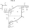
- FIG. 3is an elevation view of a further embodiment of a disposable-based dialysis fluid air separation chamber using a low pressure inlet flow of dialysis fluid to the air separation chamber.
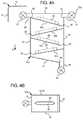
- FIGS. 4A and 4Bare elevation and top views, respectively, of one embodiment of a disposable-based dialysis fluid air separation chamber configured to cause a serpentine flow of dialysis fluid within the air separation chamber.
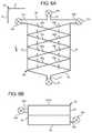
- FIGS. 5A and 5Bare elevation and top views, respectively, of another embodiment of a disposable-based dialysis fluid air separation chamber configured to cause a cyclone flow of dialysis fluid within the air separation chamber.
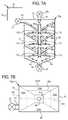
- FIGS. 6A and 6Bare elevation and top views, respectively, of a further embodiment of a disposable-based dialysis fluid air separation chamber configured to cause a cyclone flow of dialysis fluid within the air separation chamber.
- FIGS. 7A and 7Bare elevation and top views, respectively, of yet another embodiment of a disposable-based dialysis fluid air separation chamber configured to cause a cyclone flow of dialysis fluid within the air separation chamber.
- FIGS. 8A and 8Bare elevation and top views, respectively, of still another embodiment of a disposable-based dialysis fluid air separation chamber configured to cause a cyclone flow of dialysis fluid within the air separation chamber.
- FIG. 9is an elevation view of one embodiment of a disposable-based dialysis fluid air separation chamber configured to cause a nozzled flow leading to a vacuum separation of gas bubbles from dialysis fluid.
- FIG. 10is an elevation view of an embodiment of a disposable-based dialysis fluid air separation chamber configured to cause a film flow of dialysis fluid within the air separation chamber.
- dialysis disposablee.g. cassette 10 having air trap 50 illustrates one embodiment of the present disclosure (air trap 50 refers generally to air traps 50 a to 50 j discussed herein). While air traps 50 are shown herein in connection with a disposable set described below, the separation chambers are alternatively stand-alone apparatuses that operate independent of the disposable cassette.
- Dialysis cassette 10is operable with any type of dialysis instrument such as a peritoneal dialysis instrument, hemodialysis, hemofiltration, hemodiafiltration or continuous renal replacement therapy instrument.
- Dialysis cassette 10can hold a dialysis fluid such as dialysate or blood.
- the dialysis fluidcan be premixed or cassette 10 can carry a component of dialysate such as a dialysate concentrate.
- Dialysis cassette 10 in one embodimentis part of a disposable set which includes one or more supply bag, a drain bag, a heater bag, and tubing running from those bags (not illustrated) to dialysis cassette 10 .
- Dialysis cassette 10 in one embodimentis disposable, however, dialysis cassette 10 can be cleaned for multiple uses in which the air traps described herein are used multiple times.
- Dialysis cassette 10includes a rigid portion have a cassette top wall 12 , a cassette side wall 14 and a cassette bottom wall 16 . Suitable materials for the rigid portion include polyvinyl chloride (“PVC”), acrylic, ABS, polycarbonate and polyolefin blends.
- the rigid portion of cassette 10also includes a base wall or mid-plane 18 which separates cassette 10 into first and second sides.
- the side of mid-plane 18 illustrated in FIG. 1includes pump chambers 20 a and 20 b which here are part of a pneumatically and/or electromechanically operated diaphragm pump.
- cassette 10includes peristaltic pumping tubes that operate with a peristaltic pump actuator of the dialysis instrument.
- Cassette 10also includes valve chambers, such as air separation inlet valve chamber 22 , air separation outlet valve chambers 24 a and 24 b and air separation air vent valve chambers 26 a and 26 b .
- the valve chamberscan also be pneumatically and/or electromechanically operated.
- cassette 10 divided by mid-plane 18can include flow paths for example and/or other valve chambers and/or pump chambers. It should be appreciated that cassette 10 can have different structural layouts without affecting the performance air separation chamber 50 . Air separation chamber 50 can be located on either side of mid-plane 18 for space purposes or other reasons related to component layout.
- the rigid portion of cassette 10defines the wall or walls of pump chambers 20 a and 20 b that operate with a flexible cassette sheeting 28 which is welded, heat sealed or solvent bonded to rigid walls 12 , 14 , 16 , etc., of the rigid portion of cassette 10 .
- Suitable cassette sheeting 28includes polyvinyl chloride (“PVC”), polypropylene/polyethylene blends, polypropylene or Kraton blends, polyester, polyolefin, and ULDPE.
- the suitable PVC sheetingcan include, for example, monolayer PVC films, non-DEHP PVC monolayer films, monolayer non-PVC and multilayer non-PVC films (wherein different layers are chosen to provide strength, weldability, abrasion resistance and minimal “sticktion” to other materials such as rigid cassette materials). Multiple layers can be co-extruded or laminated together.
- Cassette sheeting 28is also used to open and close valve chambers, such as chambers 22 , 24 a , 24 b , 26 a and 26 b .
- the dialysis instrumentincludes a processor and memory that operate a program which controls when valve chambers 22 , 24 a , 24 b , 26 a and 26 b are opened or closed.
- inlet and outlet valve chambers 22 , 24 a and 24 bcan be sequenced during priming to fill air separation chamber 50 .
- Inlet and outlet valve chambers 22 , 24 a and 24 bare open during dialysis fluid delivery and/or blood pumping to remove air from those fluids.
- inlet and outlet valve chambers 22 , 24 a and 24 bare shown directly in front of and behind the air separation chambers, it is also contemplated to move one or both the inlet and outlet valves 22 , 24 a and 24 b further away from the air separation chamber.
- One or both of inlet and outlet valve chambers 22 , 24 a and 24 bcan be configured to control flow to multiple places within cassette 10 , including the air separation chamber.
- the memory and processingare also programmed to operate vent valve chambers 26 a and 26 b so as to remove air from the air separation chamber in a manner that does not affect the sterility of the dialysis fluid flowing through cassette 10 .
- the processing and memorycan operate with an air pressure signal from a pressure sensor (or level signal from a level sensor) monitoring the pressure of air (level of fluid) within the air separation chamber. The signal is monitored to determine when to perform the air purge valve sequence of valve chambers 26 a and 26 b .
- the processing and memoryare programmed to perform the valve sequence for valve chambers 26 a and 26 b at set intervals.
- Cassette 10 in FIG. 1also includes a plurality of rigid ports extending from one of the walls such as cassette top wall 12 .
- cassette 10includes a vent port 30 , which operates with vent valve chambers 26 a and 26 b and air separation chamber 50 .
- Cassette 10also includes other ports, such as one or more fluid supply port 32 , a drain port 34 , a to- or from—heater port 36 and other ports, such as patient port and heater bag port.
- Vent port 30can vent air from air separation chamber 50 to atmosphere or to drain in different embodiments.
- Cassette 10can include other apparatuses (not illustrated) such as pressure sensing areas, heater flow path areas, and additional pumping areas such as heparin and/or saline pumping areas.
- Cassette 10further includes alignment notches 42 and 44 that mate with alignment projections 102 and 104 of dialysis instrument 100 when cassette 10 is loaded into instrument 100 .
- Mating apparatuses 42 / 102 and 44 / 104(and potentially others, not limited to two) ensure that cassette 10 is aligned correctly with corresponding actuators, sensors and other hardware located within instrument 100 .
- instrument 100can include a level sensor or pressure sensor to sense when air vent valves should be sequenced to vent air from the air separation chamber.
- Mating apparatuses 42 / 102 and 44 / 104ensure that an air collection portion of the chamber is aligned properly with the pressure chamber or that cassette 10 is positioned so that the level sensor reads the level of dialysis fluid correctly.
- FIG. 1shows one embodiment of the air separation chamber or air trap of the present disclosure, namely, air separation chamber 50 a .
- Air separation chamber 50 aincludes a first side wall 52 , a bottom wall 54 , an second side wall 56 and a top wall 58 .
- walls 52 to 58can extend from mid-plane 18 such that mid-plane 18 forms one of the broad sides of air separation chamber 50 .
- mid-plane 18extends along the outside of walls 52 to 58 but not inside air separation 50 , such that walls 52 to 58 extend the entire width of cassette 10 .
- both broad surfaces of air separation chamber 50can be made of flexible sheeting 28 .
- one or both of the broad surfaces of air separation chamber 50are made of the rigid material, wherein sheeting 28 is then welded to the rigid broad surfaces of air separation chamber 50 .
- the profile shape of air separation chamber 50can be welded or solvent bonded to walls 52 to 58 .
- the sheetingis welded or solvent bonded to the edges of the rigid profile sides of air separation chamber 50 .
- the outer broad surface of air separation 50can be flexible sheet 28 or a rigid piece that is welded or solvent bonded to walls 52 to 58 .
- Inlet valve chamber 22opens and closes an inlet pathway 62 , while outlet valve chambers 24 a and 24 b open and close outlet pathways 64 .
- Inlet pathway 62communicates with air separation chamber 50 via inlet 66 which is formed in bottom wall 54 .
- Outlet pathways 64communicate with air separation chamber 50 via outlets 68 also formed in wall 54 of air separation chamber 50 .
- each valve chambercan be either an inlet or outlet valve, e.g., for priming purposes each valve chamber 22 , 24 a and 24 b can be an inlet valve chamber that primes air removal chamber 50 up to vent line 70 .
- Vent valves 26 a and 26 bopen and close a vent line 70 .
- Vent line 70communicates with vent port 30 and with air separation chamber 50 via a vent outlet 72 formed in top wall 58 of air separation chamber 50 .
- Dual vent valves 26 a and 26 ballow the processing and memory of the dialysis instrument to isolate a slug of air in vent line 70 before vent valve 26 b is opened, allowing the air to escape via vent port 30 to atmosphere or drain.
- vent valve 26 ais opened allowing vent line 70 to become pressurized with air. Once line 70 becomes pressurized, valve 26 a is closed and valve 26 b is opened, relieving the pressure in vent line 70 .
- inlet pathway 62 , outlet pathways 64 and vent line 70are at least substantially parallel to each other.
- Walls 52 and 56are at least substantially parallel to each other.
- Bottom wall 54 and top wall 58are angled to smooth flow and to reduce trapped air.
- Air separation chamber 50 acan be configured differently.
- the profile shapecan be alternatively substantially rectangular, and the inlet pathway 62 and outlet pathways 64 can alternatively extend to side walls 52 and 56 .
- a single outlet 64 and valve chamber 24 acan be provided instead of two dialysis fluid outlets.
- Inlet pathway 62 of air separation chamber 50 aextends upwardly into the chamber when cassette 10 is placed into the dialysis instrument. Dialysis fluid flows against gravity g from the opening 66 of inlet pathway 62 into the air collection area 84 of the air separation chamber. A splash plate 80 is provided to prevent the dialysis fluid from splashing up into vent line 70 . The dialysis fluid spills over from the top of inlet pathway 62 into dialysis fluid pool 82 . The dialysis fluid flows from pool 82 , through one or more outlet pathway 64 and to the patient or elsewhere, e.g., to a fluid heater.
- Air separation chamber 50 apromotes air separation through multiple modes. First, forcing the dialysis fluid to flow over inlet opening 66 of inlet tube 62 separates the dialysis fluid, exposing more of its surface area to the atmosphere. Exposing fluid surface area also exposes gas bubbles trapped within the fluid, allowing the bubbles to escape to air collection portion 84 . Second, once the dialysis fluid falls into fluid pool 82 , buoyancy forces in the pool push remaining air bubbles up to air collection portion 84 .
- Air separation chamber 50 b operable with cassette 10 of FIG. 2illustrates another splash and pool embodiment of the present disclosure.
- inlet pathway 62 , outlet pathways 64 and vent line 70are again at least substantially parallel to each other.
- Walls 52 and 56are also at least substantially parallel to each other.
- Top wall 58is angled to smooth flow and reduce the possibility of trapping air.
- Bottom wall 54is angled from inlet 62 to outlet 64 to allow gravity g to create a generally right-to-left, downward flow.
- Air separation chamber 50 bcan be configured differently, for example, the profile shape can be alternatively substantially rectangular, or the inlet pathway 62 and outlet pathway 64 can alternatively extend to side walls 52 and 56 .
- Inlet pathway 62 of air separation chamber 50 bextends upwardly into and along the right side of the chamber 50 b when cassette 10 is placed into the dialysis instrument.
- Dialysis fluidflows against gravity g from the opening 66 of inlet pathway 62 into the air collection area 84 of the air separation chamber.
- a splash plate 80is provided to prevent the dialysis fluid from splashing up into vent line 70 .
- the dialysis fluidspills over from the top of inlet pathway 62 and into dialysis fluid pool 82 .
- the dialysis fluidflows from pool 82 , through outlet pathway 64 and to the patient or elsewhere.
- Air separation chamber 50 blike chamber 50 a , promotes air separation by flowing the dialysis over inlet opening 66 , separating the dialysis fluid, exposing more of its surface area to the atmosphere and exposing gas bubbles trapped within the fluid to atmosphere. Moreover, once the dialysis fluid falls into fluid pool 82 , buoyancy forces in the pool push remaining air bubbles up to air collection portion 84 .
- Air separation chamber 50 c operable with cassette 10 of FIG. 3illustrates a further splash and pool embodiment of the present disclosure.
- inlet pathway 62 and vent line 70are again at least substantially horizontal and parallel to each other.
- Vent line 70is located elevationally above inlet 62 .
- Outlet 64is disposed vertically and below inlet 62 or vent line 70 .
- Walls 52 and 56are also at least substantially parallel to each other.
- Top wall 58is angled to smooth flow and to reduce trapped air.
- Bottom wall 54is angled from second side 56 to outlet 64 to allow gravity g to create a generally right-to-left, downward flow.
- Dialysis fluidflows horizontally through inlet pathway 62 of air separation chamber when cassette 10 is placed into the dialysis instrument. Dialysis fluid flows from the opening 66 of inlet pathway 62 into the air collection area 84 of the air separation chamber. The dialysis fluid hits a splash plate 80 which breaks apart the dialysis fluid. The dialysis fluid spills down from splash plate 80 into dialysis fluid pool 82 . The dialysis fluid flows from pool 82 , through outlet pathway 64 and to the patient or elsewhere.
- Air separation chamber 50 clike chambers 50 a and 50 b , promotes air separation by impinging the dialysis fluid against splash plate 80 and separating the dialysis fluid, exposing more of its surface area to the atmosphere and thereby exposing gas bubbles trapped within the fluid to atmosphere. Moreover, once the dialysis fluid falls into fluid pool 82 , buoyancy forces in the pool push remaining air bubbles up to air collection portion 84 .
- baffles and funnels per air separation chambercan vary from the number illustrated.
- Air separation chamber 50 dis one embodiment of an air separation chamber that creates a serpentine dialysis fluid flow to separate air and gas bubbles from the dialysis fluid.
- Inlet pathway 62 and vent line 70are again at least substantially horizontal and parallel to or aligned with each other.
- Outlet 64is disposed vertically at bottom wall 54 . Walls 52 and 56 are also at least substantially parallel to each other. Bottom wall 54 is angled from first side 52 to outlet 64 to allow gravity g to create a generally left-to-right, downward flow at the bottom of air separation chamber 50 d.
- air separation chamber 50 dcan extend from mid-plane 18 or span the entire width of cassette 10 . If extending from mid-plane 18 , the outer surface of air separation chamber 50 d can be flexible sheeting 28 (as indicated) or a piece of rigid material. If extending the entire width of cassette 10 , the outer surfaces of air separation chamber 50 d can be flexible sheeting 28 , two pieces of rigid material, or a combination of same. Thus, depending on the configuration of air separation chamber 50 d , baffles 80 a to 80 d together with any needed support gusseting (not shown) can extend from sidewalls 52 and 56 or from sidewalls 52 and 56 and mid-plane 18 .
- Air separation chamber 50 dincludes alternating baffles 80 a to 80 d .
- Each baffleincludes or defines an air opening 86 which is surrounded by a border 88 as seen in the top view of FIG. 4B .
- Baffles 80 a to 80 ddo not travel all the way from side wall 52 to side wall 56 , but leave a gap 90 for the dialysis fluid to fall to the next lower baffle 80 b , 80 c or 80 d .
- Borders 88prevent, at least partially, dialysis fluid from falling though air openings 86 directly to the bottom wall 54 . Borders 88 also create a central opening for air or gas to travel upwards to vent line 70 .
- Baffles 80 a to 80 dincrease the dialysis fluid flow path and the degassing time as the fluid flows down and back and forth along the alternating baffles.
- Air separation chamber 50 dis structured to force air towards the middle of the air separation chamber, while the dialysis fluid flows around borders 88 . Air separation chamber 50 d achieves back-and-forth if not spiral fluid flow. Air separation is performed primarily through buoyancy.
- Air separation chamber 50 eoperable with cassette 10 of FIGS. 5A and 5B , is one embodiment of an air separation chamber that creates a cyclone or spiral dialysis fluid flow to separate air and gas bubbles from the dialysis fluid.
- Inlet pathway 62 and vent line 70are again at least substantially horizontal and parallel to or aligned with each other.
- Outlet 64is disposed vertically at bottom wall 54 . Walls 52 and 56 are also at least substantially parallel to each other.
- Bottom wall 54is angled from second side 56 to outlet 64 to allow gravity g to create a generally right-to-left, downward flow at the bottom of air separation chamber 50 e.
- air separation chamber 50 ecan extend from mid-plane 18 or span the entire width of cassette 10 . If extending from mid-plane 18 , the outer surface of air separation chamber 50 e can be flexible sheeting 28 (as indicated) or a piece of rigid material. If extending the entire width of cassette 10 , the outer surfaces of air separation chamber 50 e can be flexible sheeting 28 , two pieces of rigid material, or a combination of same. Thus, depending on the configuration of air separation chamber 50 e , baffles 80 a to 80 e together with any needed support gusseting (not shown) can extend from sidewalls 52 and 56 or from sidewalls 52 and 56 and mid-plane 18 .
- Air separation chamber 50 eincludes alternating baffles 80 a to 80 e .
- Each bafflehas a width w of less than half a total width W of air separation chamber 50 e .
- alternating pairs of bafflesleave an air gap 86 between the baffles.
- the baffles 80 a to 80 eextend from side 52 to side 56 and include a turn 92 that directs fluid onto the next lower baffle 80 b to 80 e .
- Each baffles 80 a to 80 eincludes a border 94 that bends with turn 92 and that prevents, at least partially, dialysis fluid from falling though air gap 86 directly to the bottom wall 54 .
- Successive gaps 86create a central opening for air or gas to travel upwards to vent line 70 .
- Baffles 80 a to 80 eincrease the dialysis fluid flow path and the degassing time as the fluid flows down and back-and-forth along the alternating baffles.
- Air separation chamber 50 eis structured to force air towards the middle of the air separation chamber while the dialysis fluid flows around borders 94 .
- Air separation chamber 50 dachieves back-and-forth and spiral fluid flow. The spiraling flow is assumed to produce a centripetal effect in which heavier fluid gravitates to the outside of baffles 80 a to 80 e , while lighter air separates towards the inside of the baffles and rises through gaps 86 . Air separation is performed additionally through buoyancy via the elongated fluid flow path.
- Air separation chamber 50 fis another embodiment of an air separation chamber that creates a cyclone or spiral dialysis fluid flow to separate air and gas bubbles from the dialysis fluid.
- chamber 50 fincludes dual inlet valve chambers 22 a and 22 b , which open and close dual inlet pathways 62 a and 62 b respectively.
- Chamber 50 fcreates dual spiraling paths using dual inlet pathways 62 a and 62 b which are least substantially horizontal and parallel to or aligned with each other.
- Vent line 70is located at top wall 58 of chamber 50 f .
- Outlet 64is disposed vertically at bottom wall 54 . Walls 52 and 56 are at least substantially parallel to each other.
- Bottom wall 54is dual-angled from sides 52 and 56 to outlet 64 in the middle of chamber 50 f.
- air separation chamber 50 fcan extend from mid-plane 18 or span the entire width of cassette 10 . If extending from mid-plane 18 , the outer surface of air separation chamber 50 f can be flexible sheeting 28 (as indicated) or a piece of rigid material. If extending the entire width of cassette 10 , the outer surfaces of air separation chamber 50 f can be flexible sheeting 28 , two pieces of rigid material, or a combination of same.
- rear baffles 80 b , 80 d , 80 f and 80 h together with any needed support gussetingcan extend from sidewalls 52 and 56 or from sidewalls 52 and 56 and mid-plane 18 .
- Baffles 80 a , 80 c , 80 e and 80 gextend from sidewalls 52 and 56 , including any needed support gusseting (not shown).
- Air separation chamber 50 fincludes dual pairs of alternating baffles 80 a to 80 h .
- One pair of alternating bafflesincludes baffles 80 a , 80 c , 80 e and 80 g .
- the other pair of alternating bafflesincludes baffles 80 b , 80 d , 80 f and 80 h .
- the two pairsspiral around one another.
- Each bafflehas a width w of approximately or slightly less than half a total width W of air separation chamber 50 f .
- the dual alternating pairs of bafflesleave air paths from bottom to top indicated by the arrows in FIG. 6A . That is, air weaves up around the alternating plates on the left and right side of chamber 50 f .
- the baffles 80 a to 80 hextend from side 52 to side 56 .
- Turns 92 and borders 94are not provided in the illustrated embodiment but may in some form be provided if desired.
- Baffles 80 a to 80 hincrease the dialysis fluid flow path and the degassing time as the fluid flows down and back-and-forth along the dual sets of spiraling baffles.
- Air separation chamber 50 fachieves back-and-forth and spiral fluid flow.
- the spiraling flowis again assumed to produce a centripetal effect in which heavier fluid gravitates to the outside of baffles 80 a to 80 h , while lighter air separates towards the inside of the baffles. Air separation is performed additionally through buoyancy via the elongated dual fluid flow paths.
- Air separation chamber 50 gis another embodiment of an air separation chamber that creates a cyclone or spiral dialysis fluid flow to separate air and gas bubbles from the dialysis fluid.
- Air separation chamber 50 gincludes un upper inlet pathway 62 , a vent line 70 located at top wall 58 of chamber 50 g , and an outlet 64 disposed vertically at bottom wall 54 .
- Walls 52 and 56are at least substantially parallel to each other.
- Bottom wall 54is dual-angled from sides 52 and 56 to outlet 64 located in the middle of chamber 50 g.
- Air separation chamber 50 gcreates a series of cyclones via mating pairs of four-sided flow funnels 80 a to 80 c that funnel dialysis fluid in a cyclone manner through a central hole 81 in each funnel and around an air column 98 of an associated baffle 96 a to 96 c .
- Baffles 96 a to 96 creceive the dialysis fluid from the central hole 81 of each funnel 80 a to 80 c and spread the dialysis fluid outwardly for the next funneling of the dialysis fluid.
- baffle 96 afunnels dialysis fluid to funnel 80 b ; baffle 96 b funnels dialysis fluid to funnel 80 c ; and baffle 96 c funnels dialysis fluid to bottom wall 54 .
- the illustrated embodimentaccordingly includes four separate funnels or cyclones from funnels 80 a to 80 c and bottom wall 54 .
- air separation chamber 50 gcan extend from mid-plane 18 or span the entire width of cassette 10 . If extending from mid-plane 18 , the outer surface of air separation chamber 50 g can be flexible sheeting 28 (as indicated) or a piece of rigid material. If extending the entire width of cassette 10 , the outer surfaces of air separation chamber 50 g can be flexible sheeting 28 , two pieces of rigid material, or a combination of same.
- funnels 80 a to 80 c and baffles 96 a to 96 c together with any needed support gussetingcan extend from sidewalls 52 and 56 or from sidewalls 52 and 56 and mid-plane 18 .
- baffles 96 a to 96 care fixed within air separation chamber 50 g via support walls 102 .
- Funnels 80 a to 80 care four sided as seen in FIG. 7B , with side 104 a attached to wall 52 and side 104 c attached to wall 56 .
- Sides 104 b and 104 dcan be attached to rigid pieces (e.g., wall 104 d to mid-plane 18 ), fixed to flexible sheets 28 or press-fit against flexible sheets.
- FIG. 7Balso shows inlet 62 offset from center to project dialysis fluid into air separation chamber 50 g at wall 104 b in order to aid in the formation of the first cyclone flow through funnel 80 a.
- the arrangement of air separation chamber 50 gproduces an elongated flow path of dialysis fluid as indicated by the arrowed solid line in FIG. 7A .
- the fluidis forced through multiple funnels, each separating air form the fluid. Air is encouraged through a central air column formed by the series of columns 98 of baffles 96 a to 96 c .
- the spiraling flow of each funnelis again assumed to produce a centripetal effect in which heavier fluid gravitates to the outside of the funnels, while lighter air separates towards the inside of the funnels. Air separation is performed additionally through buoyancy via the elongated series fluid flow pathway.
- Air separation chamber 50 his another embodiment of an air separation chamber that creates a cyclone or spiral dialysis fluid flow to separate air and gas bubbles from the dialysis fluid.
- Air separation chamber 50 hincludes un upper inlet pathway 62 , a vent line 70 located at top wall 58 of chamber 50 h , and an outlet 64 disposed vertically at the bottom of the air separation chamber 50 h .
- Walls 52 and 56 as shownangle inwardly towards each other from top wall 58 in a funnel-like manner.
- FIG. 8Aalso shows that walls 52 and 56 are curved to form an oval or elliptical shape with cassette sheeting 28 when the sheeting is sucked outwardly as discussed below.
- air separation chamber 50 hspans the entire width of cassette 10 .
- the outer surfaces of air separation chamber 50 hare flexible sheeting 28 that is welded, adhered, solvent bonded, etc. to side walls 52 and 56 .
- Cassette 10is loaded into dialysis instrument 100 such that instrument chamber forming shells 106 a and 106 b , each having a pneumatic port 108 , come into operable engagement with sheeting 28 on respective sides of air separation chamber 50 h of dialysis cassette 10 .
- dialysis instrument 100induces a vacuum at ports 108 of chamber forming shells 106 a and 106 b which pulls sheeting 28 on both sides of cassette 10 at the air separation chamber 50 h against the inner walls of shells 106 a and 106 b .
- the shape of shells 106 a and 106 b in combination with the rounded surfaces of side walls 52 and 56form a funneled oval or elliptical-like volume that is very conducive to forming a funneled, cyclone flow of dialysis fluid.
- the funneled cyclone of dialysis fluidflows from inlet 62 , around and around the sheeting 28 and side walls 52 and 56 and down to outlet 24 .
- inlet 62is angled or jogged at side wall 52 in order to inject flow initially towards one of the extended sheets 28 .
- side walls 52 and 56can have baffles or flow directors to either obstruct the cyclone or to aid the cyclone as desired.
- air separation chamber 50 hproduces an elongated flow path of dialysis fluid. Air is encouraged to move upwardly at the center of the chamber. The spiraling flow is again assumed to produce a centripetal effect in which heavier fluid gravitates to expanded sheeting 28 , while lighter air separates at the center of chamber 50 h . Air separation is performed additionally through buoyancy via the elongated spiraled fluid flow pathway.
- Air separation chamber 50 ioperable with cassette 10 of FIG. 9 , illustrates one embodiment of a venturi or negative pressure air separation chamber that pulls fluid under a vacuum within a closed volume “away from” entrained air, leaving air in the volume.
- Air separation chamber 50 iincludes inlet pathway 62 leading to side wall 52 .
- Sidewall 52is configured to expand the inlet flow of dialysis fluid to a beginning of a nozzle section of chamber 50 i which is formed via top wall 58 and bottom wall 54 .
- Walls 52 to 58can be cylindrical or rectangular in cross-section as desired and formed of only rigid material or rigid material in combination with sheeting 28 .
- top wall 58 and bottom wall 54can come together to form a cylindrical nozzle section.
- wall 58 and bottom wall 54can be curved (similar to walls 52 and 56 of chamber 50 h ) together with nozzle and flexible sheeting side walls 28 (which can be sucked outwardly to have rounded surfaces as shown in connection with chamber 50 h ).
- the nozzle section of chamber 50 inarrows towards exit pathway 64 and exit valve 24 .
- Narrowed exit pathway 64is placed in fluid communication with a fixed volume bulb 110 .
- the nozzleis constructed such that it can create a vacuum.
- Bulb 110has a large enough volume so as not to necessitate drainage by a few milliliters.
- the cross-section of narrowed exit pathway 64can be rather small in relation to bulb 110 .
- Fixed volume bulb 110is either entirely rigid or made with sheeting that is sucked against instrument 100 to form a fixed volume. Dialysis fluid 82 that rises within fixed volume bulb 82 is subject to negative pressure due to a venturi effect of the nozzled flow through outlet 64 .
- the negative pressure placed on fluid 82tends to create a negative pressure in air collection portion 84 of bulb 110 .
- the negative gage pressurehas two effects on the air separation. First, such pressure will withdraw dissolved gases out of solution due to changes in the solubility and introduce the dissolved gases to the buoyant environment within bulb 110 . Second, bubble of known size d 1 will increase in diameter d 2 (where d 2 >d 1 ), allowing for faster rise times for the bubbles in the appropriate flow environment. Chamber 50 i can be combined with a buoyancy pool (like below) if needed to separate risable bubbles not collected in bulb 110 .
- Air separation chamber 50 joperable with cassette 10 of FIG. 10 , illustrates one embodiment of a film-producing/buoyancy pool air separation chamber.
- inlet line 62forms a thin fluid path, e.g., such as a thin liquid film that is 0.5′′ wide (12 mm wide) and 0.02′′ thick (0.5 mm wide), which produces a thin film or stream of fluid exiting opening 66 into a collection volume 112 having a liquid pool 82 and air collection area 84 .
- Forcing the inlet to flow into a thin film or streamincreases the exposed surface area of the dialysis fluid and promotes air separation as described above.
- the thin filmwill also ensure bubbles larger than the size of the film thickness will explode on their way to the collection chamber and become eliminated.
Landscapes
- Health & Medical Sciences (AREA)
- Heart & Thoracic Surgery (AREA)
- Engineering & Computer Science (AREA)
- Urology & Nephrology (AREA)
- Vascular Medicine (AREA)
- Hematology (AREA)
- Public Health (AREA)
- Biomedical Technology (AREA)
- Veterinary Medicine (AREA)
- Life Sciences & Earth Sciences (AREA)
- Animal Behavior & Ethology (AREA)
- General Health & Medical Sciences (AREA)
- Anesthesiology (AREA)
- Emergency Medicine (AREA)
- Chemical & Material Sciences (AREA)
- Chemical Kinetics & Catalysis (AREA)
- Water Supply & Treatment (AREA)
- Cardiology (AREA)
- External Artificial Organs (AREA)
Abstract
Description
Claims (8)
Priority Applications (2)
| Application Number | Priority Date | Filing Date | Title |
|---|---|---|---|
| US11/865,552US7871462B2 (en) | 2007-10-01 | 2007-10-01 | Dialysis systems having air separation chambers with internal structures to enhance air removal |
| US12/979,764US7988768B2 (en) | 2007-10-01 | 2010-12-28 | Dialysis systems having spiraling fluid air separation chambers |
Applications Claiming Priority (1)
| Application Number | Priority Date | Filing Date | Title |
|---|---|---|---|
| US11/865,552US7871462B2 (en) | 2007-10-01 | 2007-10-01 | Dialysis systems having air separation chambers with internal structures to enhance air removal |
Related Child Applications (1)
| Application Number | Title | Priority Date | Filing Date |
|---|---|---|---|
| US12/979,764ContinuationUS7988768B2 (en) | 2007-10-01 | 2010-12-28 | Dialysis systems having spiraling fluid air separation chambers |
Publications (2)
| Publication Number | Publication Date |
|---|---|
| US20090084721A1 US20090084721A1 (en) | 2009-04-02 |
| US7871462B2true US7871462B2 (en) | 2011-01-18 |
Family
ID=40506967
Family Applications (2)
| Application Number | Title | Priority Date | Filing Date |
|---|---|---|---|
| US11/865,552Active2029-05-06US7871462B2 (en) | 2007-10-01 | 2007-10-01 | Dialysis systems having air separation chambers with internal structures to enhance air removal |
| US12/979,764ActiveUS7988768B2 (en) | 2007-10-01 | 2010-12-28 | Dialysis systems having spiraling fluid air separation chambers |
Family Applications After (1)
| Application Number | Title | Priority Date | Filing Date |
|---|---|---|---|
| US12/979,764ActiveUS7988768B2 (en) | 2007-10-01 | 2010-12-28 | Dialysis systems having spiraling fluid air separation chambers |
Country Status (1)
| Country | Link |
|---|---|
| US (2) | US7871462B2 (en) |
Cited By (9)
| Publication number | Priority date | Publication date | Assignee | Title |
|---|---|---|---|---|
| US9101709B2 (en) | 2002-06-04 | 2015-08-11 | Fresenius Medical Care Deutschland Gmbh | Dialysis fluid cassettes and related systems and methods |
| WO2019051394A1 (en)* | 2017-09-11 | 2019-03-14 | Fresenius Medical Care Holdings, Inc. | Hydrophobic filters for air management in dialysis machines |
| US10456517B2 (en)* | 2007-09-05 | 2019-10-29 | Gambro Lundia Ab | Infusion site for improved mixing of fluids |
| US11712501B2 (en) | 2019-11-12 | 2023-08-01 | Fresenius Medical Care Deutschland Gmbh | Blood treatment systems |
| US11730871B2 (en) | 2019-11-12 | 2023-08-22 | Fresenius Medical Care Deutschland Gmbh | Blood treatment systems |
| US11752247B2 (en) | 2019-11-12 | 2023-09-12 | Fresenius Medical Care Deutschland Gmbh | Blood treatment systems |
| US11925736B2 (en) | 2019-11-12 | 2024-03-12 | Fresenius Medical Care Deutschland Gmbh | Blood treatment systems |
| US12285553B2 (en) | 2019-11-12 | 2025-04-29 | Fresenius Medical Care Deutschland Gmbh | Blood treatment systems |
| US12329890B2 (en) | 2019-11-12 | 2025-06-17 | Fresenius Medical Care Deutschland Gmbh | Blood treatment systems |
Families Citing this family (57)
| Publication number | Priority date | Publication date | Assignee | Title |
|---|---|---|---|---|
| US9604014B2 (en) | 2004-05-21 | 2017-03-28 | Clearline Md, Llc | System for detecting and removing a gas bubble from a vascular infusion line |
| US8197231B2 (en) | 2005-07-13 | 2012-06-12 | Purity Solutions Llc | Diaphragm pump and related methods |
| US7871391B2 (en)* | 2005-10-21 | 2011-01-18 | Fresenius Medical Care Holdings, Inc. | Extracorporeal fluid circuit |
| WO2009049235A2 (en)* | 2007-10-12 | 2009-04-16 | Deka Products Limited Partnership | Systems, devices and methods for cardiopulmonary treatment and procedures |
| US8114276B2 (en) | 2007-10-24 | 2012-02-14 | Baxter International Inc. | Personal hemodialysis system |
| US8663463B2 (en)* | 2009-02-18 | 2014-03-04 | Fresenius Medical Care Holdings, Inc. | Extracorporeal fluid circuit and related components |
| US8192401B2 (en) | 2009-03-20 | 2012-06-05 | Fresenius Medical Care Holdings, Inc. | Medical fluid pump systems and related components and methods |
| JP2012524557A (en)* | 2009-04-23 | 2012-10-18 | フレゼニウス メディカル ケア ドイッチェランド ゲゼルシャフト ミット ベシュレンクテル ハフツング | Receiving means for receiving medical fluid, external functional means and medical device |
| ES2582030T3 (en)* | 2009-04-23 | 2016-09-08 | Fresenius Medical Care Deutschland Gmbh | Air separator, external functional device, circulatory system and treatment device |
| WO2011008858A1 (en) | 2009-07-15 | 2011-01-20 | Fresenius Medical Care Holdings, Inc. | Medical fluid cassettes and related systems and methods |
| US9220832B2 (en) | 2010-01-07 | 2015-12-29 | Fresenius Medical Care Holdings, Inc. | Dialysis systems and methods |
| US8500994B2 (en) | 2010-01-07 | 2013-08-06 | Fresenius Medical Care Holdings, Inc. | Dialysis systems and methods |
| US8506684B2 (en) | 2010-12-15 | 2013-08-13 | Fresenius Medical Care Holdings, Inc. | Gas release devices for extracorporeal fluid circuits and related methods |
| WO2012087798A2 (en) | 2010-12-20 | 2012-06-28 | Fresenius Medical Care Holdings, Inc. | Medical fluid cassettes and related systems and methods |
| US9624915B2 (en) | 2011-03-09 | 2017-04-18 | Fresenius Medical Care Holdings, Inc. | Medical fluid delivery sets and related systems and methods |
| WO2012129501A2 (en) | 2011-03-23 | 2012-09-27 | Nxstage Medical, Inc. | Peritoneal dialysis systems, devices, and methods |
| US9861733B2 (en) | 2012-03-23 | 2018-01-09 | Nxstage Medical Inc. | Peritoneal dialysis systems, devices, and methods |
| MX341315B (en) | 2011-04-21 | 2016-08-12 | Fresenius Medical Care Holdings Inc | Medical fluid pumping systems and related devices and methods. |
| DE102011110472A1 (en)* | 2011-07-29 | 2013-01-31 | Fresenius Medical Care Deutschland Gmbh | Method and devices for removing gas accumulations from a clot trap of extracorporeal blood circulation |
| CN103889481B (en) | 2011-08-02 | 2016-03-09 | 美敦力公司 | Hemodialysis system with flow path with controlled compliance volume |
| EP2744537B1 (en) | 2011-08-16 | 2018-01-24 | Medtronic, Inc. | Modular hemodialysis system |
| CN102350012B (en)* | 2011-10-29 | 2014-05-28 | 北京梅德厚普科技有限公司 | Stock solution filtration and exhaust unit and hematoma remover based on same |
| US9610392B2 (en) | 2012-06-08 | 2017-04-04 | Fresenius Medical Care Holdings, Inc. | Medical fluid cassettes and related systems and methods |
| US9500188B2 (en) | 2012-06-11 | 2016-11-22 | Fresenius Medical Care Holdings, Inc. | Medical fluid cassettes and related systems and methods |
| GB2510321B (en)* | 2012-11-12 | 2018-01-31 | Biosurgical S L | Agitation apparatus |
| US10850016B2 (en) | 2013-02-01 | 2020-12-01 | Medtronic, Inc. | Modular fluid therapy system having jumpered flow paths and systems and methods for cleaning and disinfection |
| US10010663B2 (en) | 2013-02-01 | 2018-07-03 | Medtronic, Inc. | Fluid circuit for delivery of renal replacement therapies |
| US9623164B2 (en) | 2013-02-01 | 2017-04-18 | Medtronic, Inc. | Systems and methods for multifunctional volumetric fluid control |
| US10543052B2 (en) | 2013-02-01 | 2020-01-28 | Medtronic, Inc. | Portable dialysis cabinet |
| US9561323B2 (en) | 2013-03-14 | 2017-02-07 | Fresenius Medical Care Holdings, Inc. | Medical fluid cassette leak detection methods and devices |
| US9433721B2 (en) | 2013-06-25 | 2016-09-06 | Fresenius Medical Care Holdings, Inc. | Vial spiking assemblies and related methods |
| US10117985B2 (en) | 2013-08-21 | 2018-11-06 | Fresenius Medical Care Holdings, Inc. | Determining a volume of medical fluid pumped into or out of a medical fluid cassette |
| DK3052212T3 (en)* | 2013-09-30 | 2017-11-20 | Tetra Laval Holdings & Finance | PROCEDURE FOR BREATHING A LIQUID |
| US10098993B2 (en) | 2014-12-10 | 2018-10-16 | Medtronic, Inc. | Sensing and storage system for fluid balance |
| US9713665B2 (en)* | 2014-12-10 | 2017-07-25 | Medtronic, Inc. | Degassing system for dialysis |
| US10874787B2 (en) | 2014-12-10 | 2020-12-29 | Medtronic, Inc. | Degassing system for dialysis |
| US9895479B2 (en) | 2014-12-10 | 2018-02-20 | Medtronic, Inc. | Water management system for use in dialysis |
| JP6335333B2 (en)* | 2014-12-25 | 2018-05-30 | アサヒカセイメディカルヨーロッパゲーエムベーハー | Solution generator and blood purification system |
| JP6062468B2 (en)* | 2015-03-03 | 2017-01-18 | 日機装株式会社 | Air trap chamber |
| US9974942B2 (en) | 2015-06-19 | 2018-05-22 | Fresenius Medical Care Holdings, Inc. | Non-vented vial drug delivery |
| US9945838B2 (en) | 2015-12-17 | 2018-04-17 | Fresenius Medical Care Holdings, Inc. | Extracorporeal circuit blood chamber having an integrated deaeration device |
| WO2017219311A1 (en)* | 2016-06-23 | 2017-12-28 | Medtronic, Inc. | Venous air capture chamber |
| JP6159856B2 (en)* | 2016-07-14 | 2017-07-05 | 日機装株式会社 | Air trap chamber |
| DE102017102175A1 (en)* | 2017-02-03 | 2018-08-09 | B. Braun Avitum Ag | Air separator with forced circulation |
| IT201700028854U1 (en)* | 2017-03-15 | 2018-09-15 | Cannon Spa | APPARATUS FOR DEGASSING RESINS |
| US20180344949A1 (en)* | 2017-06-02 | 2018-12-06 | Clearline Md, Llc | System for detecting and removing a gas bubble from a vascular infusion line |
| EP3641850B1 (en) | 2017-06-24 | 2024-10-09 | NxStage Medical Inc. | Peritoneal dialysis fluid preparation systems |
| US11278654B2 (en) | 2017-12-07 | 2022-03-22 | Medtronic, Inc. | Pneumatic manifold for a dialysis system |
| US11033667B2 (en) | 2018-02-02 | 2021-06-15 | Medtronic, Inc. | Sorbent manifold for a dialysis system |
| US11110215B2 (en) | 2018-02-23 | 2021-09-07 | Medtronic, Inc. | Degasser and vent manifolds for dialysis |
| JP2021516089A (en) | 2018-02-28 | 2021-07-01 | ネクステージ メディカル インコーポレイテッド | Fluid preparation and treatment equipment, methods, and systems |
| CN109580321B (en)* | 2018-11-27 | 2021-05-18 | 迪瑞医疗科技股份有限公司 | Liquid path bubble removing device and method |
| US12059517B2 (en) | 2019-05-07 | 2024-08-13 | Fresenius Medical Care Holdings, Inc. | Air management in a cassette of a dialysis machine |
| US12128165B2 (en) | 2020-04-27 | 2024-10-29 | Mozarc Medical Us Llc | Dual stage degasser |
| CN116322872A (en)* | 2020-05-28 | 2023-06-23 | 米奈特朗尼克斯神经有限公司 | Filter system and filter manifold for use therewith |
| US12318528B2 (en) | 2020-10-30 | 2025-06-03 | Mozarc Medical Us Llc | Variable orifice fistula graft |
| US20240181455A1 (en)* | 2022-12-06 | 2024-06-06 | Astrin Biosciences, Inc. | Hydro-cyclone centrifuge apheretic system |
Citations (155)
| Publication number | Priority date | Publication date | Assignee | Title |
|---|---|---|---|---|
| US250868A (en) | 1881-12-13 | Phillips abbott | ||
| US927476A (en) | 1909-02-09 | 1909-07-13 | Arthur W Barker | Natural-gas separator. |
| US1505050A (en) | 1920-02-19 | 1924-08-12 | Ohio Body | Weir meter |
| US2292007A (en) | 1941-01-22 | 1942-08-04 | American Brake Shoe & Foundry | Liquid dispensing apparatus |
| CH296007A (en) | 1951-08-31 | 1954-01-31 | Alfred Dr Torricelli | Water disinfection process and installation for carrying out the process. |
| DE1806654U (en) | 1960-01-09 | 1960-02-25 | Witte & Sutor Kondensatoren Un | LIGHTED MAKEUP PICK. |
| US3044236A (en) | 1960-07-21 | 1962-07-17 | Phillips Petroleum Co | System for removal of gases from liquids |
| US3074645A (en) | 1960-11-21 | 1963-01-22 | Bell & Gossett Co | Air separator fitting for hydronic systems |
| US3095062A (en) | 1961-11-10 | 1963-06-25 | California Research Corp | Oil change system |
| US3229445A (en) | 1961-06-21 | 1966-01-18 | Automatic Process Control Inc | Method and apparatus for continuously degassing a liquid |
| US3287885A (en) | 1964-08-05 | 1966-11-29 | Odederlin & Cie Ag | Air separator for drain pipes |
| US3295297A (en) | 1965-10-19 | 1967-01-03 | Cobe Lab | Filter and bubble trap |
| US3342019A (en) | 1964-08-12 | 1967-09-19 | Technicon Corp | Gas and liquid separator for gas analysis |
| US3412760A (en) | 1966-01-10 | 1968-11-26 | Imp Eastman Corp | Hose assembly |
| US3527572A (en) | 1965-10-11 | 1970-09-08 | A Edward Urkiewicz | Apparatus for treating blood |
| US3581464A (en) | 1968-12-16 | 1971-06-01 | Trw Inc | Method of and apparatus for separating a liquid from liquid vapor and dissolved gases |
| US3598727A (en) | 1969-04-07 | 1971-08-10 | Charles B Willock | Artificial kidney |
| US3677710A (en) | 1969-06-02 | 1972-07-18 | Nathan M Hirsch | Apparatus for washing blood cells |
| US3744492A (en) | 1971-04-07 | 1973-07-10 | S Leibinsohn | Drip chamber |
| US3769207A (en) | 1971-06-14 | 1973-10-30 | E Baer | Process of separation of emulsified or dispersed matter from water |
| US3771288A (en) | 1971-10-08 | 1973-11-13 | Tno | Device for degassing a liquid |
| US3795088A (en) | 1972-03-03 | 1974-03-05 | W Esmond | Degassing particulate matter and oil filter device |
| US3827561A (en) | 1972-09-20 | 1974-08-06 | Milton Roy Co | Deaerator for dialysis system |
| US3834386A (en) | 1972-09-07 | 1974-09-10 | Sweden Freezer | Blood drip chamber |
| US3849071A (en) | 1972-12-21 | 1974-11-19 | K Kayser | Blood-gas separating system for perfusate circulation |
| US3908653A (en) | 1974-01-23 | 1975-09-30 | Vital Assists | Blood chamber |
| GB1408319A (en) | 1971-12-23 | 1975-10-01 | Baxter Laboratories Inc | Bubble trap |
| US3964479A (en) | 1974-11-20 | 1976-06-22 | Cobe Laboratories, Inc. | Extracorporeal blood circulation system and drip chamber with adjustable blood level |
| US3976311A (en) | 1973-03-19 | 1976-08-24 | Spendlove Ray E | Tubing connector apparatus and method |
| US3985134A (en) | 1973-11-26 | 1976-10-12 | Rhone-Poulenc S.A. | Extracorporeal blood circuit |
| US3996027A (en) | 1974-10-31 | 1976-12-07 | Baxter Laboratories, Inc. | Swirling flow bubble trap |
| US4031891A (en) | 1975-11-03 | 1977-06-28 | Baxter Travenol Laboratories, Inc. | Air eliminating filter |
| US4031894A (en) | 1975-12-08 | 1977-06-28 | Alza Corporation | Bandage for transdermally administering scopolamine to prevent nausea |
| US4038190A (en) | 1973-05-30 | 1977-07-26 | Rhone-Poulenc S.A. | Fluid fractionation apparatus and method of manufacturing the same |
| US4047563A (en) | 1976-01-27 | 1977-09-13 | Japan Medical Supply Co., Ltd. | Heat exchanger for artificial heart and lung devices |
| US4048995A (en) | 1975-08-15 | 1977-09-20 | Baxter Travenol Laboratories, Inc. | Injection site |
| US4054522A (en) | 1975-09-03 | 1977-10-18 | Harry Pinkerton | Apparatus for exposing a fluid to a negative pressure |
| US4061031A (en) | 1975-11-05 | 1977-12-06 | Lars Grimsrud | Combination of flow meter and bubble trap |
| US4102655A (en) | 1977-05-02 | 1978-07-25 | Cobe Laboratories, Inc. | Bubble trap |
| US4137160A (en) | 1974-10-31 | 1979-01-30 | Baxter Travenol Laboratories, Inc. | Device for separating low density material such as gas bubbles from a liquid, and the use thereof in a dialysis delivery system |
| US4149860A (en) | 1978-06-05 | 1979-04-17 | Kulik Donald A | Gas liquid separator |
| US4151088A (en) | 1978-01-23 | 1979-04-24 | Baxter Travenol Laboratories, Inc. | Membrane diffusion device with integral heat exchanger and reservoir |
| GB1554810A (en) | 1977-10-03 | 1979-10-31 | Star Oy Ab | Method of preparing furocoumarins |
| US4191182A (en) | 1977-09-23 | 1980-03-04 | Hemotherapy Inc. | Method and apparatus for continuous plasmaphersis |
| US4200095A (en) | 1977-08-15 | 1980-04-29 | Millipore Corporation | Arrangement for intravenous administration or the like |
| US4293413A (en) | 1979-12-28 | 1981-10-06 | Baxter Travenol Laboratories, Inc. | Dialyzer blood circuit and bubble traps |
| US4304670A (en) | 1979-04-03 | 1981-12-08 | Terumo Corporation | Blood filter with air trap and distributing chamber |
| US4311137A (en) | 1980-04-30 | 1982-01-19 | Sherwood Medical Industries Inc. | Infusion device |
| US4325715A (en) | 1976-03-24 | 1982-04-20 | Bowman Donald B | Apparatus for degassing hemodialysis liquid |
| US4344777A (en) | 1980-01-07 | 1982-08-17 | Siposs George G | Directed flow bubble trap for arterial blood |
| US4345999A (en) | 1978-04-27 | 1982-08-24 | Dr. Eduard Fresenius, Chemisch-Pharmazeutische Industrie K.G., Apparatebau K.G. | Apparatus for preventing the entry of air into an artificial organ |
| US4345919A (en) | 1981-01-19 | 1982-08-24 | Texas Medical Products, Inc. | Degasser for biological fluids |
| US4353368A (en) | 1977-12-23 | 1982-10-12 | Ceske Vysoke Uceni Technicke | Device for hemodialysis |
| US4363641A (en) | 1981-07-02 | 1982-12-14 | General Electric Company | Liquid degasser with self-throttling exhaust orifice |
| US4368118A (en) | 1980-01-07 | 1983-01-11 | Siposs George G | Blood-air separator and filter |
| GB2061755B (en) | 1979-10-16 | 1983-06-22 | Akers Mek Verksted As | Deaerating liquid |
| US4427009A (en) | 1981-06-30 | 1984-01-24 | Minnesota Mining And Manufacturing Company | Integrated cardioplegia delivery system |
| US4433971A (en) | 1981-06-30 | 1984-02-28 | Minnesota Mining And Manufacturing Company | Integrated cardioplegia delivery system |
| US4486188A (en) | 1980-08-14 | 1984-12-04 | Applied Medical Devices, Inc. | Bone marrow transplant method and apparatus |
| US4493705A (en) | 1982-08-10 | 1985-01-15 | Bentley Laboratories, Inc. | Blood reservoir |
| EP0058325B1 (en) | 1981-02-16 | 1985-03-27 | Gambro Dialysatoren K.G. | Flow-through chamber forming part of a blood duct |
| US4512163A (en) | 1981-06-30 | 1985-04-23 | Minnesota Mining And Manufacturing Company | Integrated cardioplegia delivery system |
| US4531937A (en) | 1983-01-24 | 1985-07-30 | Pacesetter Systems, Inc. | Introducer catheter apparatus and method of use |
| US4568333A (en) | 1983-04-12 | 1986-02-04 | Sawyer Philip Nicholas | Valve arrangement especially suitable for preventing introduction of air into vascular systems |
| US4583981A (en) | 1981-11-27 | 1986-04-22 | Alza Corporation | Parenteral controlled therapy, using a porous matrix with parenteral agent |
| US4586925A (en) | 1982-09-10 | 1986-05-06 | Gambro Lundia Ab | Hose set for extracorporeal treatment of blood and similar liquids |
| US4622032A (en) | 1984-10-27 | 1986-11-11 | Terumo Kabushiki Kaisha | Blood reservoir |
| US4643715A (en) | 1982-09-09 | 1987-02-17 | Terumo Kabushiki Kaisha | Artificial organ and method for manufacture thereof |
| US4643713A (en) | 1984-11-05 | 1987-02-17 | Baxter Travenol Laboratories, Inc. | Venous reservoir |
| US4666598A (en) | 1985-06-25 | 1987-05-19 | Cobe Laboratories, Inc. | Apparatus for use with fluid flow transfer device |
| US4681606A (en) | 1986-02-26 | 1987-07-21 | Cobe Laboratories, Inc. | Drip chamber |
| US4722725A (en) | 1983-04-12 | 1988-02-02 | Interface Biomedical Laboratories, Inc. | Methods for preventing the introduction of air or fluid into the body of a patient |
| US4722731A (en) | 1985-04-08 | 1988-02-02 | Vailancourt Vincent L | Air check valve |
| US4734269A (en) | 1985-06-11 | 1988-03-29 | American Hospital Supply Corporation | Venous reservoir bag with integral high-efficiency bubble removal system |
| EP0143340B1 (en) | 1983-11-29 | 1988-06-08 | Gambro Lundia AB | Arrangement for the venting of a liquid |
| US4806135A (en) | 1988-03-01 | 1989-02-21 | Siposs George G | Bubble trap for phase-separating gas bubbles from flowing liquids |
| US4932987A (en) | 1989-05-25 | 1990-06-12 | Jorge Molina | Extra corporeal air eliminator |
| US4941875A (en) | 1979-07-18 | 1990-07-17 | Brennan John F | I.V. system for successive administration of two or more solutions at different rates |
| US4946439A (en) | 1988-08-15 | 1990-08-07 | Critikon, Inc. | Dual source parenteral infusion system with secondary infusion module |
| USD311061S (en) | 1987-09-21 | 1990-10-02 | Airsep Corporation | Air separator |
| US4976685A (en) | 1988-06-15 | 1990-12-11 | Block Jr Frank E | Method of blood-gas interface control in surgical gas traps |
| US4997464A (en) | 1990-03-23 | 1991-03-05 | Kopf Henry B | Deaeration apparatus |
| GB2212739B (en) | 1987-10-21 | 1991-08-21 | Hick Hargreaves & Co Ltd | Liquid deaerating apparatus |
| US5047147A (en) | 1983-11-23 | 1991-09-10 | Hospal Industrie | Single-needle artificial kidneys |
| US5049492A (en) | 1990-03-14 | 1991-09-17 | The United States Of America As Represented By The United States National Aeronautics And Space Administration | Biofilm monitoring coupon system and method of use |
| US5059173A (en) | 1990-04-04 | 1991-10-22 | Sacco John J | IV apparatus |
| US5061365A (en) | 1991-01-22 | 1991-10-29 | Utterberg David S | Medical fluid flow set |
| US5061236A (en) | 1990-07-16 | 1991-10-29 | Baxter International Inc. | Venous reservoir with improved inlet configuration and integral screen for bubble removal |
| US5112480A (en) | 1987-07-07 | 1992-05-12 | Terumo Kabushiki Kaisha | Blood reservoir |
| EP0318993B1 (en) | 1987-12-04 | 1992-06-03 | Terumo Kabushiki Kaisha | Blood filter |
| US5167921A (en) | 1986-07-14 | 1992-12-01 | Baxter International Inc. | Liquid and gas separation system |
| US5178763A (en) | 1990-04-13 | 1993-01-12 | Hospal Industrie | Method and apparatus for preparing a substitution liquid |
| EP0350675B1 (en) | 1988-06-21 | 1993-03-10 | Terumo Kabushiki Kaisha | Blood reservoir |
| US5204000A (en) | 1992-01-31 | 1993-04-20 | Zcl Mfg Canada Inc. | Tank for separating water and hydrocarbon fuels from contaminated water |
| US5228889A (en) | 1991-03-01 | 1993-07-20 | Hospal Industrie | Device for eliminating bubbles of gas in a flowing liquid |
| US5246560A (en) | 1991-10-04 | 1993-09-21 | Electric Power Research Institute, Inc. | Apparatus for monitoring biofilm activity |
| US5268077A (en) | 1991-02-27 | 1993-12-07 | Sulzer Esher Wyss Gmbh | Apparatus and method for deaerating or degassing a paper stock suspension |
| US5328461A (en) | 1992-04-30 | 1994-07-12 | Utterberg David S | Blow molded venous drip chamber for hemodialysis |
| US5356376A (en) | 1990-03-08 | 1994-10-18 | Zoran Milijasevic | Flow controllers for fluid infusion sets |
| US5358481A (en) | 1993-06-03 | 1994-10-25 | Research Medical, Inc. | Apparatus and methods for controlling mixtures of blood and cardioplegia |
| US5368555A (en) | 1992-12-29 | 1994-11-29 | Hepatix, Inc. | Organ support system |
| US5394732A (en) | 1993-09-10 | 1995-03-07 | Cobe Laboratories, Inc. | Method and apparatus for ultrasonic detection of air bubbles |
| US5411705A (en) | 1994-01-14 | 1995-05-02 | Avecor Cardiovascular Inc. | Combined cardiotomy and venous blood reservoir |
| US5421815A (en) | 1993-12-14 | 1995-06-06 | Nof Corporation | Method for blood dialysis using anticoagulent composition |
| US5429595A (en) | 1992-11-12 | 1995-07-04 | Wright, Jr.; Fred G. | Arterial safety air diverter |
| US5441636A (en) | 1993-02-12 | 1995-08-15 | Cobe Laboratories, Inc. | Integrated blood treatment fluid module |
| US5468388A (en) | 1993-07-01 | 1995-11-21 | Sartorius Ag | Filter module with degassing feature |
| US5489385A (en) | 1993-02-11 | 1996-02-06 | Gambro Dialysatoren Gmbh & Co. Kg | Drip chamber and/or expansion chamber with integral filter |
| US5503801A (en) | 1993-11-29 | 1996-04-02 | Cobe Laboratories, Inc. | Top flow bubble trap apparatus |
| US5509895A (en) | 1993-12-14 | 1996-04-23 | Nof Corporation | Air trap chamber device for blood dialysis circuit containing an anticoagulant composition |
| US5520640A (en) | 1992-04-30 | 1996-05-28 | Utterberg; David S. | Blood air trap chamber |
| US5578070A (en) | 1992-04-30 | 1996-11-26 | Medisystems Technology Corporation | Blow molded venous drip chamber for hemodialysis |
| US5591251A (en) | 1993-11-29 | 1997-01-07 | Cobe Laboratories, Inc. | Side flow bubble trap apparatus and method |
| US5643250A (en) | 1992-08-07 | 1997-07-01 | O'donnell, Jr.; Francis E. | Laser probe hand piece |
| US5650071A (en) | 1995-06-07 | 1997-07-22 | Cobe Laboratories, Inc. | Technique for priming and recirculating fluid through a dialysis machine to prepare the machine for use |
| US5681294A (en) | 1995-09-21 | 1997-10-28 | Abbott Laboratories | Fluid delivery set |
| US5683355A (en) | 1995-05-29 | 1997-11-04 | Dideco S.P.A. | Cardiotomy reservoir with internal filter |
| EP0587251B1 (en) | 1989-05-31 | 1998-03-11 | Baxter International Inc. | Blood/gas separator and flow system |
| US5730730A (en) | 1995-09-29 | 1998-03-24 | Darling, Jr.; Phillip H. | Liquid flow rate control device |
| US5763266A (en) | 1989-06-15 | 1998-06-09 | The Regents Of The University Of Michigan | Methods, compositions and devices for maintaining and growing human stem and/or hematopoietics cells |
| US5800597A (en) | 1997-01-21 | 1998-09-01 | Whatman Inc. | Integral coalescer filter-membrane device to provide a filtered gas stream and system employing such device |
| US5830185A (en) | 1995-10-12 | 1998-11-03 | Instrumentarium Corp. | Position-independent fluid trap |
| US5849065A (en) | 1996-04-27 | 1998-12-15 | Fresenius Ag | Device for separating gas bubbles from fluids, in particular blood |
| US5851202A (en) | 1994-08-15 | 1998-12-22 | Gambro Ab | Drip chamber head |
| US5858239A (en) | 1997-02-14 | 1999-01-12 | Aksys, Ltd. | Methods and apparatus for adjustment of blood drip chamber of dialysis machines using touchscreen interface |
| US5863421A (en) | 1995-02-13 | 1999-01-26 | Aksys, Ltd. | Hemodialysis machine with automatic priming by induced pressure pulses |
| US5895368A (en) | 1996-09-23 | 1999-04-20 | Medisystems Technology Corporation | Blood set priming method and apparatus |
| US5928889A (en) | 1998-02-13 | 1999-07-27 | S.C. Johnson & Son, Inc. | Protocol for simulated natural biofilm formation |
| US5931990A (en) | 1997-12-03 | 1999-08-03 | Coronator | Tank for removing unabsorbed gas from a mixture of unabsorbed gas and liquid |
| US5951870A (en) | 1997-10-21 | 1999-09-14 | Dsu Medical Corporation | Automatic priming of blood sets |
| US5980741A (en) | 1997-08-01 | 1999-11-09 | Medisystems Technology Corporation | Bubble trap with flat side having multipurpose supplemental ports |
| US5983947A (en) | 1997-03-03 | 1999-11-16 | Medisystems Technology Corporation | Docking ports for medical fluid sets |
| US5989318A (en) | 1998-05-19 | 1999-11-23 | International Fuel Cells Corporation | Apparatus for separating water from a two-phase stream |
| US6019824A (en) | 1998-06-09 | 2000-02-01 | Medisystems Technology Corporation | Bubble trap chamber |
| US6046806A (en) | 1998-03-25 | 2000-04-04 | The United States Of America As Represented By The Secretary Of The Army | Flow-through cell culture chamber |
| US6051134A (en) | 1997-03-28 | 2000-04-18 | Medisystems Technology Corporation | Bubble trap having common inlet/outlet tube |
| US6053967A (en) | 1993-09-01 | 2000-04-25 | Fresenius Ag | Air separator |
| US6066111A (en) | 1996-12-05 | 2000-05-23 | Convergenza Ag | Method of blood-gas separation device and separating device |
| US6071269A (en) | 1998-05-13 | 2000-06-06 | Medisystems Technology Corporation | Blood set and chamber |
| US6117342A (en) | 1996-11-26 | 2000-09-12 | Medisystems Technology Corporation | Bubble trap with directed horizontal flow and method of using |
| US6176903B1 (en) | 1996-05-22 | 2001-01-23 | Fresenius Medical Care Deutschland Gmbh | Device for removing gases from fluids |
| US6187198B1 (en) | 1997-10-21 | 2001-02-13 | Dsu Medical Corporation | Automatic priming of connected blood sets |
| US6251167B1 (en) | 1999-10-21 | 2001-06-26 | Berson Research Corp. | Machine and process for removing dissolved gasses from liquids |
| US6312414B1 (en) | 1996-12-05 | 2001-11-06 | Alexander Brockhoff | Blood-gas separation device |
| US20010042441A1 (en) | 2000-05-18 | 2001-11-22 | Geoff Purdom | Bubble Trap |
| US6357600B1 (en) | 1998-07-17 | 2002-03-19 | Gvs S.R.L. | Drip chamber for transfusion dialysis infusion kits and the like |
| US6391541B1 (en) | 1999-05-28 | 2002-05-21 | Kurt E. Petersen | Apparatus for analyzing a fluid sample |
| US6391638B1 (en) | 1996-09-26 | 2002-05-21 | Metabogal, Ltd. | Cell/tissue culturing device and method |
| US6481455B2 (en) | 1998-09-01 | 2002-11-19 | Vernon C. Maine Pllc | Bubble trap for blood |
| US6514255B1 (en) | 2000-02-25 | 2003-02-04 | Bret Ferree | Sublaminar spinal fixation apparatus |
| US6537356B1 (en) | 1999-08-06 | 2003-03-25 | Nathaniel M. Soriano | Gas and solid trap for an intravenous line |
| US20040019313A1 (en) | 2002-07-19 | 2004-01-29 | Childers Robert W. | Systems, methods and apparatuses for pumping cassette-based therapies |
| US6755801B2 (en) | 1998-12-01 | 2004-06-29 | Dsu Medical Corporation | Dialysis pressure monitoring with clot suppression |
| US6827862B1 (en) | 1997-05-09 | 2004-12-07 | Alexander Brockhoff | Method and device for removing gas from gas containing blood |
| WO2006120415A1 (en)* | 2005-05-06 | 2006-11-16 | Imi Vision Limited | Dialysis machine |
Family Cites Families (2)
| Publication number | Priority date | Publication date | Assignee | Title |
|---|---|---|---|---|
| US6517732B1 (en)* | 1995-12-13 | 2003-02-11 | Convergenza Ag | Method of removal of air from blood |
| WO2008053287A1 (en)* | 2006-10-31 | 2008-05-08 | Ehud Milo | Extraction of gas from infused fluid |
- 2007
- 2007-10-01USUS11/865,552patent/US7871462B2/enactiveActive
- 2010
- 2010-12-28USUS12/979,764patent/US7988768B2/enactiveActive
Patent Citations (168)
| Publication number | Priority date | Publication date | Assignee | Title |
|---|---|---|---|---|
| US250868A (en) | 1881-12-13 | Phillips abbott | ||
| US927476A (en) | 1909-02-09 | 1909-07-13 | Arthur W Barker | Natural-gas separator. |
| US1505050A (en) | 1920-02-19 | 1924-08-12 | Ohio Body | Weir meter |
| US2292007A (en) | 1941-01-22 | 1942-08-04 | American Brake Shoe & Foundry | Liquid dispensing apparatus |
| CH296007A (en) | 1951-08-31 | 1954-01-31 | Alfred Dr Torricelli | Water disinfection process and installation for carrying out the process. |
| DE1806654U (en) | 1960-01-09 | 1960-02-25 | Witte & Sutor Kondensatoren Un | LIGHTED MAKEUP PICK. |
| US3044236A (en) | 1960-07-21 | 1962-07-17 | Phillips Petroleum Co | System for removal of gases from liquids |
| US3074645A (en) | 1960-11-21 | 1963-01-22 | Bell & Gossett Co | Air separator fitting for hydronic systems |
| US3229445A (en) | 1961-06-21 | 1966-01-18 | Automatic Process Control Inc | Method and apparatus for continuously degassing a liquid |
| US3095062A (en) | 1961-11-10 | 1963-06-25 | California Research Corp | Oil change system |
| US3287885A (en) | 1964-08-05 | 1966-11-29 | Odederlin & Cie Ag | Air separator for drain pipes |
| US3342019A (en) | 1964-08-12 | 1967-09-19 | Technicon Corp | Gas and liquid separator for gas analysis |
| US3527572A (en) | 1965-10-11 | 1970-09-08 | A Edward Urkiewicz | Apparatus for treating blood |
| US3295297A (en) | 1965-10-19 | 1967-01-03 | Cobe Lab | Filter and bubble trap |
| US3412760A (en) | 1966-01-10 | 1968-11-26 | Imp Eastman Corp | Hose assembly |
| US3581464A (en) | 1968-12-16 | 1971-06-01 | Trw Inc | Method of and apparatus for separating a liquid from liquid vapor and dissolved gases |
| US3598727A (en) | 1969-04-07 | 1971-08-10 | Charles B Willock | Artificial kidney |
| US3677710A (en) | 1969-06-02 | 1972-07-18 | Nathan M Hirsch | Apparatus for washing blood cells |
| US3744492A (en) | 1971-04-07 | 1973-07-10 | S Leibinsohn | Drip chamber |
| US3769207A (en) | 1971-06-14 | 1973-10-30 | E Baer | Process of separation of emulsified or dispersed matter from water |
| US3771288A (en) | 1971-10-08 | 1973-11-13 | Tno | Device for degassing a liquid |
| GB1408319A (en) | 1971-12-23 | 1975-10-01 | Baxter Laboratories Inc | Bubble trap |
| US3795088A (en) | 1972-03-03 | 1974-03-05 | W Esmond | Degassing particulate matter and oil filter device |
| US3834386A (en) | 1972-09-07 | 1974-09-10 | Sweden Freezer | Blood drip chamber |
| US3827561A (en) | 1972-09-20 | 1974-08-06 | Milton Roy Co | Deaerator for dialysis system |
| US3849071A (en) | 1972-12-21 | 1974-11-19 | K Kayser | Blood-gas separating system for perfusate circulation |
| US3976311A (en) | 1973-03-19 | 1976-08-24 | Spendlove Ray E | Tubing connector apparatus and method |
| US4038190A (en) | 1973-05-30 | 1977-07-26 | Rhone-Poulenc S.A. | Fluid fractionation apparatus and method of manufacturing the same |
| US3985134A (en) | 1973-11-26 | 1976-10-12 | Rhone-Poulenc S.A. | Extracorporeal blood circuit |
| US3908653A (en) | 1974-01-23 | 1975-09-30 | Vital Assists | Blood chamber |
| US3996027A (en) | 1974-10-31 | 1976-12-07 | Baxter Laboratories, Inc. | Swirling flow bubble trap |
| US4137160A (en) | 1974-10-31 | 1979-01-30 | Baxter Travenol Laboratories, Inc. | Device for separating low density material such as gas bubbles from a liquid, and the use thereof in a dialysis delivery system |
| US3964479A (en) | 1974-11-20 | 1976-06-22 | Cobe Laboratories, Inc. | Extracorporeal blood circulation system and drip chamber with adjustable blood level |
| US4048995A (en) | 1975-08-15 | 1977-09-20 | Baxter Travenol Laboratories, Inc. | Injection site |
| US4054522A (en) | 1975-09-03 | 1977-10-18 | Harry Pinkerton | Apparatus for exposing a fluid to a negative pressure |
| US4031891A (en) | 1975-11-03 | 1977-06-28 | Baxter Travenol Laboratories, Inc. | Air eliminating filter |
| US4061031A (en) | 1975-11-05 | 1977-12-06 | Lars Grimsrud | Combination of flow meter and bubble trap |
| US4031894A (en) | 1975-12-08 | 1977-06-28 | Alza Corporation | Bandage for transdermally administering scopolamine to prevent nausea |
| US4047563A (en) | 1976-01-27 | 1977-09-13 | Japan Medical Supply Co., Ltd. | Heat exchanger for artificial heart and lung devices |
| US4325715A (en) | 1976-03-24 | 1982-04-20 | Bowman Donald B | Apparatus for degassing hemodialysis liquid |
| US4102655A (en) | 1977-05-02 | 1978-07-25 | Cobe Laboratories, Inc. | Bubble trap |
| US4200095A (en) | 1977-08-15 | 1980-04-29 | Millipore Corporation | Arrangement for intravenous administration or the like |
| US4191182A (en) | 1977-09-23 | 1980-03-04 | Hemotherapy Inc. | Method and apparatus for continuous plasmaphersis |
| GB1554810A (en) | 1977-10-03 | 1979-10-31 | Star Oy Ab | Method of preparing furocoumarins |
| US4353368A (en) | 1977-12-23 | 1982-10-12 | Ceske Vysoke Uceni Technicke | Device for hemodialysis |
| US4151088A (en) | 1978-01-23 | 1979-04-24 | Baxter Travenol Laboratories, Inc. | Membrane diffusion device with integral heat exchanger and reservoir |
| US4345999A (en) | 1978-04-27 | 1982-08-24 | Dr. Eduard Fresenius, Chemisch-Pharmazeutische Industrie K.G., Apparatebau K.G. | Apparatus for preventing the entry of air into an artificial organ |
| US4149860A (en) | 1978-06-05 | 1979-04-17 | Kulik Donald A | Gas liquid separator |
| US4304670A (en) | 1979-04-03 | 1981-12-08 | Terumo Corporation | Blood filter with air trap and distributing chamber |
| US4941875A (en) | 1979-07-18 | 1990-07-17 | Brennan John F | I.V. system for successive administration of two or more solutions at different rates |
| GB2061755B (en) | 1979-10-16 | 1983-06-22 | Akers Mek Verksted As | Deaerating liquid |
| US4293413A (en) | 1979-12-28 | 1981-10-06 | Baxter Travenol Laboratories, Inc. | Dialyzer blood circuit and bubble traps |
| US4344777A (en) | 1980-01-07 | 1982-08-17 | Siposs George G | Directed flow bubble trap for arterial blood |
| US4368118A (en) | 1980-01-07 | 1983-01-11 | Siposs George G | Blood-air separator and filter |
| US4311137A (en) | 1980-04-30 | 1982-01-19 | Sherwood Medical Industries Inc. | Infusion device |
| US4486188A (en) | 1980-08-14 | 1984-12-04 | Applied Medical Devices, Inc. | Bone marrow transplant method and apparatus |
| US4345919A (en) | 1981-01-19 | 1982-08-24 | Texas Medical Products, Inc. | Degasser for biological fluids |
| EP0058325B1 (en) | 1981-02-16 | 1985-03-27 | Gambro Dialysatoren K.G. | Flow-through chamber forming part of a blood duct |
| US4427009A (en) | 1981-06-30 | 1984-01-24 | Minnesota Mining And Manufacturing Company | Integrated cardioplegia delivery system |
| US4433971A (en) | 1981-06-30 | 1984-02-28 | Minnesota Mining And Manufacturing Company | Integrated cardioplegia delivery system |
| US4512163A (en) | 1981-06-30 | 1985-04-23 | Minnesota Mining And Manufacturing Company | Integrated cardioplegia delivery system |
| US4363641A (en) | 1981-07-02 | 1982-12-14 | General Electric Company | Liquid degasser with self-throttling exhaust orifice |
| US4583981A (en) | 1981-11-27 | 1986-04-22 | Alza Corporation | Parenteral controlled therapy, using a porous matrix with parenteral agent |
| US4493705A (en) | 1982-08-10 | 1985-01-15 | Bentley Laboratories, Inc. | Blood reservoir |
| US4643715A (en) | 1982-09-09 | 1987-02-17 | Terumo Kabushiki Kaisha | Artificial organ and method for manufacture thereof |
| US4586925A (en) | 1982-09-10 | 1986-05-06 | Gambro Lundia Ab | Hose set for extracorporeal treatment of blood and similar liquids |
| EP0106026B2 (en) | 1982-09-10 | 1990-06-13 | Gambro Lundia AB | A tube set intended for extracorporeal treatment of blood and similar perishable liquids |
| US4531937A (en) | 1983-01-24 | 1985-07-30 | Pacesetter Systems, Inc. | Introducer catheter apparatus and method of use |
| US4722725A (en) | 1983-04-12 | 1988-02-02 | Interface Biomedical Laboratories, Inc. | Methods for preventing the introduction of air or fluid into the body of a patient |
| US4568333A (en) | 1983-04-12 | 1986-02-04 | Sawyer Philip Nicholas | Valve arrangement especially suitable for preventing introduction of air into vascular systems |
| US5047147A (en) | 1983-11-23 | 1991-09-10 | Hospal Industrie | Single-needle artificial kidneys |
| EP0143340B1 (en) | 1983-11-29 | 1988-06-08 | Gambro Lundia AB | Arrangement for the venting of a liquid |
| US4622032A (en) | 1984-10-27 | 1986-11-11 | Terumo Kabushiki Kaisha | Blood reservoir |
| US4643713A (en) | 1984-11-05 | 1987-02-17 | Baxter Travenol Laboratories, Inc. | Venous reservoir |
| US4722731A (en) | 1985-04-08 | 1988-02-02 | Vailancourt Vincent L | Air check valve |
| US4734269A (en) | 1985-06-11 | 1988-03-29 | American Hospital Supply Corporation | Venous reservoir bag with integral high-efficiency bubble removal system |
| US4666598A (en) | 1985-06-25 | 1987-05-19 | Cobe Laboratories, Inc. | Apparatus for use with fluid flow transfer device |
| US4681606A (en) | 1986-02-26 | 1987-07-21 | Cobe Laboratories, Inc. | Drip chamber |
| US5167921A (en) | 1986-07-14 | 1992-12-01 | Baxter International Inc. | Liquid and gas separation system |
| US5112480A (en) | 1987-07-07 | 1992-05-12 | Terumo Kabushiki Kaisha | Blood reservoir |
| USD311061S (en) | 1987-09-21 | 1990-10-02 | Airsep Corporation | Air separator |
| GB2212739B (en) | 1987-10-21 | 1991-08-21 | Hick Hargreaves & Co Ltd | Liquid deaerating apparatus |
| EP0318993B1 (en) | 1987-12-04 | 1992-06-03 | Terumo Kabushiki Kaisha | Blood filter |
| US4806135A (en) | 1988-03-01 | 1989-02-21 | Siposs George G | Bubble trap for phase-separating gas bubbles from flowing liquids |
| US4976685A (en) | 1988-06-15 | 1990-12-11 | Block Jr Frank E | Method of blood-gas interface control in surgical gas traps |
| EP0350675B1 (en) | 1988-06-21 | 1993-03-10 | Terumo Kabushiki Kaisha | Blood reservoir |
| US4946439A (en) | 1988-08-15 | 1990-08-07 | Critikon, Inc. | Dual source parenteral infusion system with secondary infusion module |
| US4932987A (en) | 1989-05-25 | 1990-06-12 | Jorge Molina | Extra corporeal air eliminator |
| EP0587251B1 (en) | 1989-05-31 | 1998-03-11 | Baxter International Inc. | Blood/gas separator and flow system |
| US5763266A (en) | 1989-06-15 | 1998-06-09 | The Regents Of The University Of Michigan | Methods, compositions and devices for maintaining and growing human stem and/or hematopoietics cells |
| US5356376A (en) | 1990-03-08 | 1994-10-18 | Zoran Milijasevic | Flow controllers for fluid infusion sets |
| US5049492A (en) | 1990-03-14 | 1991-09-17 | The United States Of America As Represented By The United States National Aeronautics And Space Administration | Biofilm monitoring coupon system and method of use |
| US4997464A (en) | 1990-03-23 | 1991-03-05 | Kopf Henry B | Deaeration apparatus |
| US5059173A (en) | 1990-04-04 | 1991-10-22 | Sacco John J | IV apparatus |
| US5178763A (en) | 1990-04-13 | 1993-01-12 | Hospal Industrie | Method and apparatus for preparing a substitution liquid |
| US5061236A (en) | 1990-07-16 | 1991-10-29 | Baxter International Inc. | Venous reservoir with improved inlet configuration and integral screen for bubble removal |
| US5061365A (en) | 1991-01-22 | 1991-10-29 | Utterberg David S | Medical fluid flow set |
| EP0501144B1 (en) | 1991-02-27 | 1995-05-24 | Voith Sulzer Stoffaufbereitung GmbH | Equipment to ventilate a paper stock suspension and its application |
| US5268077A (en) | 1991-02-27 | 1993-12-07 | Sulzer Esher Wyss Gmbh | Apparatus and method for deaerating or degassing a paper stock suspension |
| US5228889A (en) | 1991-03-01 | 1993-07-20 | Hospal Industrie | Device for eliminating bubbles of gas in a flowing liquid |
| US5246560A (en) | 1991-10-04 | 1993-09-21 | Electric Power Research Institute, Inc. | Apparatus for monitoring biofilm activity |
| US5204000A (en) | 1992-01-31 | 1993-04-20 | Zcl Mfg Canada Inc. | Tank for separating water and hydrocarbon fuels from contaminated water |
| US5605540A (en) | 1992-04-30 | 1997-02-25 | Utterberg; David S. | Blood air trap chamber |
| US5520640A (en) | 1992-04-30 | 1996-05-28 | Utterberg; David S. | Blood air trap chamber |
| US5578070A (en) | 1992-04-30 | 1996-11-26 | Medisystems Technology Corporation | Blow molded venous drip chamber for hemodialysis |
| US5328461A (en) | 1992-04-30 | 1994-07-12 | Utterberg David S | Blow molded venous drip chamber for hemodialysis |
| US5643250A (en) | 1992-08-07 | 1997-07-01 | O'donnell, Jr.; Francis E. | Laser probe hand piece |
| US5429595A (en) | 1992-11-12 | 1995-07-04 | Wright, Jr.; Fred G. | Arterial safety air diverter |
| US5368555A (en) | 1992-12-29 | 1994-11-29 | Hepatix, Inc. | Organ support system |
| US5489385A (en) | 1993-02-11 | 1996-02-06 | Gambro Dialysatoren Gmbh & Co. Kg | Drip chamber and/or expansion chamber with integral filter |
| US5441636A (en) | 1993-02-12 | 1995-08-15 | Cobe Laboratories, Inc. | Integrated blood treatment fluid module |
| US5358481A (en) | 1993-06-03 | 1994-10-25 | Research Medical, Inc. | Apparatus and methods for controlling mixtures of blood and cardioplegia |
| US5468388A (en) | 1993-07-01 | 1995-11-21 | Sartorius Ag | Filter module with degassing feature |
| US6053967A (en) | 1993-09-01 | 2000-04-25 | Fresenius Ag | Air separator |
| US5394732A (en) | 1993-09-10 | 1995-03-07 | Cobe Laboratories, Inc. | Method and apparatus for ultrasonic detection of air bubbles |
| US5674199A (en) | 1993-11-29 | 1997-10-07 | Cobe Laboratories, Inc. | Top flow bubble trap method |
| US5591251A (en) | 1993-11-29 | 1997-01-07 | Cobe Laboratories, Inc. | Side flow bubble trap apparatus and method |
| US5503801A (en) | 1993-11-29 | 1996-04-02 | Cobe Laboratories, Inc. | Top flow bubble trap apparatus |
| US5637081A (en) | 1993-12-14 | 1997-06-10 | Nof Corporation | Anticoagulant composition for use in blood dialysis circuit |
| US5509895A (en) | 1993-12-14 | 1996-04-23 | Nof Corporation | Air trap chamber device for blood dialysis circuit containing an anticoagulant composition |
| US5421815A (en) | 1993-12-14 | 1995-06-06 | Nof Corporation | Method for blood dialysis using anticoagulent composition |
| US5411705A (en) | 1994-01-14 | 1995-05-02 | Avecor Cardiovascular Inc. | Combined cardiotomy and venous blood reservoir |
| EP0776222B1 (en) | 1994-08-15 | 2003-04-16 | Gambro Ab | Drip chamber head |
| US5851202A (en) | 1994-08-15 | 1998-12-22 | Gambro Ab | Drip chamber head |
| US5863421A (en) | 1995-02-13 | 1999-01-26 | Aksys, Ltd. | Hemodialysis machine with automatic priming by induced pressure pulses |
| US5683355A (en) | 1995-05-29 | 1997-11-04 | Dideco S.P.A. | Cardiotomy reservoir with internal filter |
| US5776091A (en) | 1995-06-07 | 1998-07-07 | Cobe Laboratories, Inc. | Technique for priming and recirculating fluid through a dialysis machine to prepare the machine for use |
| US5650071A (en) | 1995-06-07 | 1997-07-22 | Cobe Laboratories, Inc. | Technique for priming and recirculating fluid through a dialysis machine to prepare the machine for use |
| US5681294A (en) | 1995-09-21 | 1997-10-28 | Abbott Laboratories | Fluid delivery set |
| US5730730A (en) | 1995-09-29 | 1998-03-24 | Darling, Jr.; Phillip H. | Liquid flow rate control device |
| US5830185A (en) | 1995-10-12 | 1998-11-03 | Instrumentarium Corp. | Position-independent fluid trap |
| US5849065A (en) | 1996-04-27 | 1998-12-15 | Fresenius Ag | Device for separating gas bubbles from fluids, in particular blood |
| US6176903B1 (en) | 1996-05-22 | 2001-01-23 | Fresenius Medical Care Deutschland Gmbh | Device for removing gases from fluids |
| US5895368A (en) | 1996-09-23 | 1999-04-20 | Medisystems Technology Corporation | Blood set priming method and apparatus |
| US6391638B1 (en) | 1996-09-26 | 2002-05-21 | Metabogal, Ltd. | Cell/tissue culturing device and method |
| US6117342A (en) | 1996-11-26 | 2000-09-12 | Medisystems Technology Corporation | Bubble trap with directed horizontal flow and method of using |
| US6312414B1 (en) | 1996-12-05 | 2001-11-06 | Alexander Brockhoff | Blood-gas separation device |
| US6066111A (en) | 1996-12-05 | 2000-05-23 | Convergenza Ag | Method of blood-gas separation device and separating device |
| US5800597A (en) | 1997-01-21 | 1998-09-01 | Whatman Inc. | Integral coalescer filter-membrane device to provide a filtered gas stream and system employing such device |
| US5858239A (en) | 1997-02-14 | 1999-01-12 | Aksys, Ltd. | Methods and apparatus for adjustment of blood drip chamber of dialysis machines using touchscreen interface |
| US5983947A (en) | 1997-03-03 | 1999-11-16 | Medisystems Technology Corporation | Docking ports for medical fluid sets |
| US6171484B1 (en) | 1997-03-03 | 2001-01-09 | Dsu Medical Corporation | Bubble trap having inlet/outlet tube and docking port |
| US6051134A (en) | 1997-03-28 | 2000-04-18 | Medisystems Technology Corporation | Bubble trap having common inlet/outlet tube |
| US6827862B1 (en) | 1997-05-09 | 2004-12-07 | Alexander Brockhoff | Method and device for removing gas from gas containing blood |
| US6010623A (en) | 1997-08-01 | 2000-01-04 | Medisystems Technology Corporation | Bubble trap with flat side |
| US5980741A (en) | 1997-08-01 | 1999-11-09 | Medisystems Technology Corporation | Bubble trap with flat side having multipurpose supplemental ports |
| US6344139B1 (en) | 1997-10-21 | 2002-02-05 | Dsu Medical Corporation | Arterial and venous blood tubing set |
| US6464878B2 (en) | 1997-10-21 | 2002-10-15 | Dsu Medical Corporation | Automatic priming of blood sets |
| US6187198B1 (en) | 1997-10-21 | 2001-02-13 | Dsu Medical Corporation | Automatic priming of connected blood sets |
| US5951870A (en) | 1997-10-21 | 1999-09-14 | Dsu Medical Corporation | Automatic priming of blood sets |
| US5931990A (en) | 1997-12-03 | 1999-08-03 | Coronator | Tank for removing unabsorbed gas from a mixture of unabsorbed gas and liquid |
| US5928889A (en) | 1998-02-13 | 1999-07-27 | S.C. Johnson & Son, Inc. | Protocol for simulated natural biofilm formation |
| US6046806A (en) | 1998-03-25 | 2000-04-04 | The United States Of America As Represented By The Secretary Of The Army | Flow-through cell culture chamber |
| US6206954B1 (en) | 1998-05-13 | 2001-03-27 | Dsu Medical Corporation | Blood set and chamber |
| US6071269A (en) | 1998-05-13 | 2000-06-06 | Medisystems Technology Corporation | Blood set and chamber |
| US5989318A (en) | 1998-05-19 | 1999-11-23 | International Fuel Cells Corporation | Apparatus for separating water from a two-phase stream |
| US6019824A (en) | 1998-06-09 | 2000-02-01 | Medisystems Technology Corporation | Bubble trap chamber |
| US6357600B1 (en) | 1998-07-17 | 2002-03-19 | Gvs S.R.L. | Drip chamber for transfusion dialysis infusion kits and the like |
| US6481455B2 (en) | 1998-09-01 | 2002-11-19 | Vernon C. Maine Pllc | Bubble trap for blood |
| US6755801B2 (en) | 1998-12-01 | 2004-06-29 | Dsu Medical Corporation | Dialysis pressure monitoring with clot suppression |
| US6391541B1 (en) | 1999-05-28 | 2002-05-21 | Kurt E. Petersen | Apparatus for analyzing a fluid sample |
| US6537356B1 (en) | 1999-08-06 | 2003-03-25 | Nathaniel M. Soriano | Gas and solid trap for an intravenous line |
| US6251167B1 (en) | 1999-10-21 | 2001-06-26 | Berson Research Corp. | Machine and process for removing dissolved gasses from liquids |
| US6514255B1 (en) | 2000-02-25 | 2003-02-04 | Bret Ferree | Sublaminar spinal fixation apparatus |
| US20010042441A1 (en) | 2000-05-18 | 2001-11-22 | Geoff Purdom | Bubble Trap |
| US6562107B2 (en) | 2000-05-18 | 2003-05-13 | Millipore Corporation | Bubble trap |
| US20040019313A1 (en) | 2002-07-19 | 2004-01-29 | Childers Robert W. | Systems, methods and apparatuses for pumping cassette-based therapies |
| WO2006120415A1 (en)* | 2005-05-06 | 2006-11-16 | Imi Vision Limited | Dialysis machine |
Cited By (13)
| Publication number | Priority date | Publication date | Assignee | Title |
|---|---|---|---|---|
| US9101709B2 (en) | 2002-06-04 | 2015-08-11 | Fresenius Medical Care Deutschland Gmbh | Dialysis fluid cassettes and related systems and methods |
| US11738132B2 (en)* | 2007-09-05 | 2023-08-29 | Gambro Lundia Ab | Infusion site for improved mixing of fluids |
| US10456517B2 (en)* | 2007-09-05 | 2019-10-29 | Gambro Lundia Ab | Infusion site for improved mixing of fluids |
| US20200016319A1 (en)* | 2007-09-05 | 2020-01-16 | Gambro Lundia Ab | Infusion site for improved mixing of fluids |
| WO2019051394A1 (en)* | 2017-09-11 | 2019-03-14 | Fresenius Medical Care Holdings, Inc. | Hydrophobic filters for air management in dialysis machines |
| AU2018330336B2 (en)* | 2017-09-11 | 2020-07-30 | Fresenius Medical Care Holdings, Inc. | Hydrophobic filters for air management in dialysis machines |
| US10806842B2 (en) | 2017-09-11 | 2020-10-20 | Fresenius Medical Care Holdings, Inc. | Hydrophobic filters for air management in dialysis machines |
| US11712501B2 (en) | 2019-11-12 | 2023-08-01 | Fresenius Medical Care Deutschland Gmbh | Blood treatment systems |
| US11730871B2 (en) | 2019-11-12 | 2023-08-22 | Fresenius Medical Care Deutschland Gmbh | Blood treatment systems |
| US11752247B2 (en) | 2019-11-12 | 2023-09-12 | Fresenius Medical Care Deutschland Gmbh | Blood treatment systems |
| US11925736B2 (en) | 2019-11-12 | 2024-03-12 | Fresenius Medical Care Deutschland Gmbh | Blood treatment systems |
| US12285553B2 (en) | 2019-11-12 | 2025-04-29 | Fresenius Medical Care Deutschland Gmbh | Blood treatment systems |
| US12329890B2 (en) | 2019-11-12 | 2025-06-17 | Fresenius Medical Care Deutschland Gmbh | Blood treatment systems |
Also Published As
| Publication number | Publication date |
|---|---|
| US20110092895A1 (en) | 2011-04-21 |
| US20090084721A1 (en) | 2009-04-02 |
| US7988768B2 (en) | 2011-08-02 |
Similar Documents
| Publication | Publication Date | Title |
|---|---|---|
| US7871462B2 (en) | Dialysis systems having air separation chambers with internal structures to enhance air removal | |
| US7892331B2 (en) | Dialysis systems having air separation chambers with internal structures to enhance air removal | |
| US7892332B2 (en) | Dialysis systems having air traps with internal structures to enhance air removal | |
| US20250108155A1 (en) | Airtrap, system and method for removing microbubbles from a fluid stream | |
| US12433979B2 (en) | Peritoneal dialysis patient line with sterilizing filter and drain bypass | |
| US11110213B2 (en) | Mixing for online medical fluid generation | |
| AU2004286782A1 (en) | Fluid distribution module and extracorporeal blood circuit including such a module | |
| US20230277738A1 (en) | Dialysis system and method including a flow path insulator | |
| EP3727494B1 (en) | Dialysis system having carbon dioxide generation and prime | |
| US20240197972A1 (en) | Priming method and system for forward osmosis |
Legal Events
| Date | Code | Title | Description |
|---|---|---|---|
| AS | Assignment | Owner name:BAXTER HEALTHCARE S.A., SWITZERLAND Free format text:ASSIGNMENT OF ASSIGNORS INTEREST;ASSIGNORS:YARDIMCI, ATIF M.;LAIRD, JAMES C.;REEL/FRAME:020544/0507 Effective date:20080215 Owner name:BAXTER INTERNATIONAL INC., ILLINOIS Free format text:ASSIGNMENT OF ASSIGNORS INTEREST;ASSIGNORS:YARDIMCI, ATIF M.;LAIRD, JAMES C.;REEL/FRAME:020544/0507 Effective date:20080215 | |
| AS | Assignment | Owner name:BAXTER HEALTHCARE S.A., SWITZERLAND Free format text:CHANGE OF CORPORATE ADDRESS;ASSIGNOR:BAXTER HEALTHCARE S.A.;REEL/FRAME:025468/0826 Effective date:20090814 | |
| STCF | Information on status: patent grant | Free format text:PATENTED CASE | |
| FPAY | Fee payment | Year of fee payment:4 | |
| MAFP | Maintenance fee payment | Free format text:PAYMENT OF MAINTENANCE FEE, 8TH YEAR, LARGE ENTITY (ORIGINAL EVENT CODE: M1552) Year of fee payment:8 | |
| MAFP | Maintenance fee payment | Free format text:PAYMENT OF MAINTENANCE FEE, 12TH YEAR, LARGE ENTITY (ORIGINAL EVENT CODE: M1553); ENTITY STATUS OF PATENT OWNER: LARGE ENTITY Year of fee payment:12 | |
| AS | Assignment | Owner name:ARES CAPITAL CORPORATION, NEW YORK Free format text:SECURITY INTEREST;ASSIGNORS:VANTIVE US HEALTHCARE LLC;GAMBRO RENAL PRODUCTS, INC.;REEL/FRAME:070076/0701 Effective date:20250131 |