US7871441B2 - Cervical fixation device - Google Patents
Cervical fixation deviceDownload PDFInfo
- Publication number
- US7871441B2 US7871441B2US11/741,200US74120007AUS7871441B2US 7871441 B2US7871441 B2US 7871441B2US 74120007 AUS74120007 AUS 74120007AUS 7871441 B2US7871441 B2US 7871441B2
- Authority
- US
- United States
- Prior art keywords
- fixation device
- cervical fixation
- arches
- proximal end
- frame
- Prior art date
- Legal status (The legal status is an assumption and is not a legal conclusion. Google has not performed a legal analysis and makes no representation as to the accuracy of the status listed.)
- Expired - Fee Related, expires
Links
Images


Classifications
- A—HUMAN NECESSITIES
- A61—MEDICAL OR VETERINARY SCIENCE; HYGIENE
- A61F—FILTERS IMPLANTABLE INTO BLOOD VESSELS; PROSTHESES; DEVICES PROVIDING PATENCY TO, OR PREVENTING COLLAPSING OF, TUBULAR STRUCTURES OF THE BODY, e.g. STENTS; ORTHOPAEDIC, NURSING OR CONTRACEPTIVE DEVICES; FOMENTATION; TREATMENT OR PROTECTION OF EYES OR EARS; BANDAGES, DRESSINGS OR ABSORBENT PADS; FIRST-AID KITS
- A61F2/00—Filters implantable into blood vessels; Prostheses, i.e. artificial substitutes or replacements for parts of the body; Appliances for connecting them with the body; Devices providing patency to, or preventing collapsing of, tubular structures of the body, e.g. stents
- A61F2/02—Prostheses implantable into the body
- A61F2/30—Joints
- A61F2/44—Joints for the spine, e.g. vertebrae, spinal discs
- A61F2/4455—Joints for the spine, e.g. vertebrae, spinal discs for the fusion of spinal bodies, e.g. intervertebral fusion of adjacent spinal bodies, e.g. fusion cages
- A—HUMAN NECESSITIES
- A61—MEDICAL OR VETERINARY SCIENCE; HYGIENE
- A61F—FILTERS IMPLANTABLE INTO BLOOD VESSELS; PROSTHESES; DEVICES PROVIDING PATENCY TO, OR PREVENTING COLLAPSING OF, TUBULAR STRUCTURES OF THE BODY, e.g. STENTS; ORTHOPAEDIC, NURSING OR CONTRACEPTIVE DEVICES; FOMENTATION; TREATMENT OR PROTECTION OF EYES OR EARS; BANDAGES, DRESSINGS OR ABSORBENT PADS; FIRST-AID KITS
- A61F2/00—Filters implantable into blood vessels; Prostheses, i.e. artificial substitutes or replacements for parts of the body; Appliances for connecting them with the body; Devices providing patency to, or preventing collapsing of, tubular structures of the body, e.g. stents
- A61F2/02—Prostheses implantable into the body
- A61F2/28—Bones
- A—HUMAN NECESSITIES
- A61—MEDICAL OR VETERINARY SCIENCE; HYGIENE
- A61F—FILTERS IMPLANTABLE INTO BLOOD VESSELS; PROSTHESES; DEVICES PROVIDING PATENCY TO, OR PREVENTING COLLAPSING OF, TUBULAR STRUCTURES OF THE BODY, e.g. STENTS; ORTHOPAEDIC, NURSING OR CONTRACEPTIVE DEVICES; FOMENTATION; TREATMENT OR PROTECTION OF EYES OR EARS; BANDAGES, DRESSINGS OR ABSORBENT PADS; FIRST-AID KITS
- A61F2/00—Filters implantable into blood vessels; Prostheses, i.e. artificial substitutes or replacements for parts of the body; Appliances for connecting them with the body; Devices providing patency to, or preventing collapsing of, tubular structures of the body, e.g. stents
- A61F2/02—Prostheses implantable into the body
- A61F2/30—Joints
- A61F2/44—Joints for the spine, e.g. vertebrae, spinal discs
- A61F2/4455—Joints for the spine, e.g. vertebrae, spinal discs for the fusion of spinal bodies, e.g. intervertebral fusion of adjacent spinal bodies, e.g. fusion cages
- A61F2/447—Joints for the spine, e.g. vertebrae, spinal discs for the fusion of spinal bodies, e.g. intervertebral fusion of adjacent spinal bodies, e.g. fusion cages substantially parallelepipedal, e.g. having a rectangular or trapezoidal cross-section
- A—HUMAN NECESSITIES
- A61—MEDICAL OR VETERINARY SCIENCE; HYGIENE
- A61F—FILTERS IMPLANTABLE INTO BLOOD VESSELS; PROSTHESES; DEVICES PROVIDING PATENCY TO, OR PREVENTING COLLAPSING OF, TUBULAR STRUCTURES OF THE BODY, e.g. STENTS; ORTHOPAEDIC, NURSING OR CONTRACEPTIVE DEVICES; FOMENTATION; TREATMENT OR PROTECTION OF EYES OR EARS; BANDAGES, DRESSINGS OR ABSORBENT PADS; FIRST-AID KITS
- A61F2/00—Filters implantable into blood vessels; Prostheses, i.e. artificial substitutes or replacements for parts of the body; Appliances for connecting them with the body; Devices providing patency to, or preventing collapsing of, tubular structures of the body, e.g. stents
- A61F2/02—Prostheses implantable into the body
- A61F2/28—Bones
- A61F2002/2835—Bone graft implants for filling a bony defect or an endoprosthesis cavity, e.g. by synthetic material or biological material
- A—HUMAN NECESSITIES
- A61—MEDICAL OR VETERINARY SCIENCE; HYGIENE
- A61F—FILTERS IMPLANTABLE INTO BLOOD VESSELS; PROSTHESES; DEVICES PROVIDING PATENCY TO, OR PREVENTING COLLAPSING OF, TUBULAR STRUCTURES OF THE BODY, e.g. STENTS; ORTHOPAEDIC, NURSING OR CONTRACEPTIVE DEVICES; FOMENTATION; TREATMENT OR PROTECTION OF EYES OR EARS; BANDAGES, DRESSINGS OR ABSORBENT PADS; FIRST-AID KITS
- A61F2/00—Filters implantable into blood vessels; Prostheses, i.e. artificial substitutes or replacements for parts of the body; Appliances for connecting them with the body; Devices providing patency to, or preventing collapsing of, tubular structures of the body, e.g. stents
- A61F2/02—Prostheses implantable into the body
- A61F2/30—Joints
- A61F2002/30001—Additional features of subject-matter classified in A61F2/28, A61F2/30 and subgroups thereof
- A61F2002/30003—Material related properties of the prosthesis or of a coating on the prosthesis
- A61F2002/30004—Material related properties of the prosthesis or of a coating on the prosthesis the prosthesis being made from materials having different values of a given property at different locations within the same prosthesis
- A61F2002/30056—Material related properties of the prosthesis or of a coating on the prosthesis the prosthesis being made from materials having different values of a given property at different locations within the same prosthesis differing in radiographic density
- A—HUMAN NECESSITIES
- A61—MEDICAL OR VETERINARY SCIENCE; HYGIENE
- A61F—FILTERS IMPLANTABLE INTO BLOOD VESSELS; PROSTHESES; DEVICES PROVIDING PATENCY TO, OR PREVENTING COLLAPSING OF, TUBULAR STRUCTURES OF THE BODY, e.g. STENTS; ORTHOPAEDIC, NURSING OR CONTRACEPTIVE DEVICES; FOMENTATION; TREATMENT OR PROTECTION OF EYES OR EARS; BANDAGES, DRESSINGS OR ABSORBENT PADS; FIRST-AID KITS
- A61F2/00—Filters implantable into blood vessels; Prostheses, i.e. artificial substitutes or replacements for parts of the body; Appliances for connecting them with the body; Devices providing patency to, or preventing collapsing of, tubular structures of the body, e.g. stents
- A61F2/02—Prostheses implantable into the body
- A61F2/30—Joints
- A61F2002/30001—Additional features of subject-matter classified in A61F2/28, A61F2/30 and subgroups thereof
- A61F2002/30003—Material related properties of the prosthesis or of a coating on the prosthesis
- A61F2002/3006—Properties of materials and coating materials
- A61F2002/30062—(bio)absorbable, biodegradable, bioerodable, (bio)resorbable, resorptive
- A—HUMAN NECESSITIES
- A61—MEDICAL OR VETERINARY SCIENCE; HYGIENE
- A61F—FILTERS IMPLANTABLE INTO BLOOD VESSELS; PROSTHESES; DEVICES PROVIDING PATENCY TO, OR PREVENTING COLLAPSING OF, TUBULAR STRUCTURES OF THE BODY, e.g. STENTS; ORTHOPAEDIC, NURSING OR CONTRACEPTIVE DEVICES; FOMENTATION; TREATMENT OR PROTECTION OF EYES OR EARS; BANDAGES, DRESSINGS OR ABSORBENT PADS; FIRST-AID KITS
- A61F2/00—Filters implantable into blood vessels; Prostheses, i.e. artificial substitutes or replacements for parts of the body; Appliances for connecting them with the body; Devices providing patency to, or preventing collapsing of, tubular structures of the body, e.g. stents
- A61F2/02—Prostheses implantable into the body
- A61F2/30—Joints
- A61F2002/30001—Additional features of subject-matter classified in A61F2/28, A61F2/30 and subgroups thereof
- A61F2002/30108—Shapes
- A61F2002/3011—Cross-sections or two-dimensional shapes
- A61F2002/30112—Rounded shapes, e.g. with rounded corners
- A—HUMAN NECESSITIES
- A61—MEDICAL OR VETERINARY SCIENCE; HYGIENE
- A61F—FILTERS IMPLANTABLE INTO BLOOD VESSELS; PROSTHESES; DEVICES PROVIDING PATENCY TO, OR PREVENTING COLLAPSING OF, TUBULAR STRUCTURES OF THE BODY, e.g. STENTS; ORTHOPAEDIC, NURSING OR CONTRACEPTIVE DEVICES; FOMENTATION; TREATMENT OR PROTECTION OF EYES OR EARS; BANDAGES, DRESSINGS OR ABSORBENT PADS; FIRST-AID KITS
- A61F2/00—Filters implantable into blood vessels; Prostheses, i.e. artificial substitutes or replacements for parts of the body; Appliances for connecting them with the body; Devices providing patency to, or preventing collapsing of, tubular structures of the body, e.g. stents
- A61F2/02—Prostheses implantable into the body
- A61F2/30—Joints
- A61F2002/30001—Additional features of subject-matter classified in A61F2/28, A61F2/30 and subgroups thereof
- A61F2002/30316—The prosthesis having different structural features at different locations within the same prosthesis; Connections between prosthetic parts; Special structural features of bone or joint prostheses not otherwise provided for
- A61F2002/30329—Connections or couplings between prosthetic parts, e.g. between modular parts; Connecting elements
- A61F2002/30331—Connections or couplings between prosthetic parts, e.g. between modular parts; Connecting elements made by longitudinally pushing a protrusion into a complementarily-shaped recess, e.g. held by friction fit
- A—HUMAN NECESSITIES
- A61—MEDICAL OR VETERINARY SCIENCE; HYGIENE
- A61F—FILTERS IMPLANTABLE INTO BLOOD VESSELS; PROSTHESES; DEVICES PROVIDING PATENCY TO, OR PREVENTING COLLAPSING OF, TUBULAR STRUCTURES OF THE BODY, e.g. STENTS; ORTHOPAEDIC, NURSING OR CONTRACEPTIVE DEVICES; FOMENTATION; TREATMENT OR PROTECTION OF EYES OR EARS; BANDAGES, DRESSINGS OR ABSORBENT PADS; FIRST-AID KITS
- A61F2/00—Filters implantable into blood vessels; Prostheses, i.e. artificial substitutes or replacements for parts of the body; Appliances for connecting them with the body; Devices providing patency to, or preventing collapsing of, tubular structures of the body, e.g. stents
- A61F2/02—Prostheses implantable into the body
- A61F2/30—Joints
- A61F2002/30001—Additional features of subject-matter classified in A61F2/28, A61F2/30 and subgroups thereof
- A61F2002/30316—The prosthesis having different structural features at different locations within the same prosthesis; Connections between prosthetic parts; Special structural features of bone or joint prostheses not otherwise provided for
- A61F2002/30329—Connections or couplings between prosthetic parts, e.g. between modular parts; Connecting elements
- A61F2002/30433—Connections or couplings between prosthetic parts, e.g. between modular parts; Connecting elements using additional screws, bolts, dowels, rivets or washers e.g. connecting screws
- A—HUMAN NECESSITIES
- A61—MEDICAL OR VETERINARY SCIENCE; HYGIENE
- A61F—FILTERS IMPLANTABLE INTO BLOOD VESSELS; PROSTHESES; DEVICES PROVIDING PATENCY TO, OR PREVENTING COLLAPSING OF, TUBULAR STRUCTURES OF THE BODY, e.g. STENTS; ORTHOPAEDIC, NURSING OR CONTRACEPTIVE DEVICES; FOMENTATION; TREATMENT OR PROTECTION OF EYES OR EARS; BANDAGES, DRESSINGS OR ABSORBENT PADS; FIRST-AID KITS
- A61F2/00—Filters implantable into blood vessels; Prostheses, i.e. artificial substitutes or replacements for parts of the body; Appliances for connecting them with the body; Devices providing patency to, or preventing collapsing of, tubular structures of the body, e.g. stents
- A61F2/02—Prostheses implantable into the body
- A61F2/30—Joints
- A61F2002/30001—Additional features of subject-matter classified in A61F2/28, A61F2/30 and subgroups thereof
- A61F2002/30316—The prosthesis having different structural features at different locations within the same prosthesis; Connections between prosthetic parts; Special structural features of bone or joint prostheses not otherwise provided for
- A61F2002/30329—Connections or couplings between prosthetic parts, e.g. between modular parts; Connecting elements
- A61F2002/30476—Connections or couplings between prosthetic parts, e.g. between modular parts; Connecting elements locked by an additional locking mechanism
- A61F2002/305—Snap connection
- A—HUMAN NECESSITIES
- A61—MEDICAL OR VETERINARY SCIENCE; HYGIENE
- A61F—FILTERS IMPLANTABLE INTO BLOOD VESSELS; PROSTHESES; DEVICES PROVIDING PATENCY TO, OR PREVENTING COLLAPSING OF, TUBULAR STRUCTURES OF THE BODY, e.g. STENTS; ORTHOPAEDIC, NURSING OR CONTRACEPTIVE DEVICES; FOMENTATION; TREATMENT OR PROTECTION OF EYES OR EARS; BANDAGES, DRESSINGS OR ABSORBENT PADS; FIRST-AID KITS
- A61F2/00—Filters implantable into blood vessels; Prostheses, i.e. artificial substitutes or replacements for parts of the body; Appliances for connecting them with the body; Devices providing patency to, or preventing collapsing of, tubular structures of the body, e.g. stents
- A61F2/02—Prostheses implantable into the body
- A61F2/30—Joints
- A61F2002/30001—Additional features of subject-matter classified in A61F2/28, A61F2/30 and subgroups thereof
- A61F2002/30316—The prosthesis having different structural features at different locations within the same prosthesis; Connections between prosthetic parts; Special structural features of bone or joint prostheses not otherwise provided for
- A61F2002/30535—Special structural features of bone or joint prostheses not otherwise provided for
- A61F2002/30576—Special structural features of bone or joint prostheses not otherwise provided for with extending fixation tabs
- A61F2002/30578—Special structural features of bone or joint prostheses not otherwise provided for with extending fixation tabs having apertures, e.g. for receiving fixation screws
- A—HUMAN NECESSITIES
- A61—MEDICAL OR VETERINARY SCIENCE; HYGIENE
- A61F—FILTERS IMPLANTABLE INTO BLOOD VESSELS; PROSTHESES; DEVICES PROVIDING PATENCY TO, OR PREVENTING COLLAPSING OF, TUBULAR STRUCTURES OF THE BODY, e.g. STENTS; ORTHOPAEDIC, NURSING OR CONTRACEPTIVE DEVICES; FOMENTATION; TREATMENT OR PROTECTION OF EYES OR EARS; BANDAGES, DRESSINGS OR ABSORBENT PADS; FIRST-AID KITS
- A61F2/00—Filters implantable into blood vessels; Prostheses, i.e. artificial substitutes or replacements for parts of the body; Appliances for connecting them with the body; Devices providing patency to, or preventing collapsing of, tubular structures of the body, e.g. stents
- A61F2/02—Prostheses implantable into the body
- A61F2/30—Joints
- A61F2002/30001—Additional features of subject-matter classified in A61F2/28, A61F2/30 and subgroups thereof
- A61F2002/30316—The prosthesis having different structural features at different locations within the same prosthesis; Connections between prosthetic parts; Special structural features of bone or joint prostheses not otherwise provided for
- A61F2002/30535—Special structural features of bone or joint prostheses not otherwise provided for
- A61F2002/30593—Special structural features of bone or joint prostheses not otherwise provided for hollow
- A—HUMAN NECESSITIES
- A61—MEDICAL OR VETERINARY SCIENCE; HYGIENE
- A61F—FILTERS IMPLANTABLE INTO BLOOD VESSELS; PROSTHESES; DEVICES PROVIDING PATENCY TO, OR PREVENTING COLLAPSING OF, TUBULAR STRUCTURES OF THE BODY, e.g. STENTS; ORTHOPAEDIC, NURSING OR CONTRACEPTIVE DEVICES; FOMENTATION; TREATMENT OR PROTECTION OF EYES OR EARS; BANDAGES, DRESSINGS OR ABSORBENT PADS; FIRST-AID KITS
- A61F2/00—Filters implantable into blood vessels; Prostheses, i.e. artificial substitutes or replacements for parts of the body; Appliances for connecting them with the body; Devices providing patency to, or preventing collapsing of, tubular structures of the body, e.g. stents
- A61F2/02—Prostheses implantable into the body
- A61F2/30—Joints
- A61F2/30721—Accessories
- A61F2/30728—Collars; Bone edge protectors
- A61F2002/30731—Bone edge protectors
- A—HUMAN NECESSITIES
- A61—MEDICAL OR VETERINARY SCIENCE; HYGIENE
- A61F—FILTERS IMPLANTABLE INTO BLOOD VESSELS; PROSTHESES; DEVICES PROVIDING PATENCY TO, OR PREVENTING COLLAPSING OF, TUBULAR STRUCTURES OF THE BODY, e.g. STENTS; ORTHOPAEDIC, NURSING OR CONTRACEPTIVE DEVICES; FOMENTATION; TREATMENT OR PROTECTION OF EYES OR EARS; BANDAGES, DRESSINGS OR ABSORBENT PADS; FIRST-AID KITS
- A61F2/00—Filters implantable into blood vessels; Prostheses, i.e. artificial substitutes or replacements for parts of the body; Appliances for connecting them with the body; Devices providing patency to, or preventing collapsing of, tubular structures of the body, e.g. stents
- A61F2/02—Prostheses implantable into the body
- A61F2/30—Joints
- A61F2/30767—Special external or bone-contacting surface, e.g. coating for improving bone ingrowth
- A61F2/30771—Special external or bone-contacting surface, e.g. coating for improving bone ingrowth applied in original prostheses, e.g. holes or grooves
- A61F2002/30772—Apertures or holes, e.g. of circular cross section
- A61F2002/30777—Oblong apertures
- A—HUMAN NECESSITIES
- A61—MEDICAL OR VETERINARY SCIENCE; HYGIENE
- A61F—FILTERS IMPLANTABLE INTO BLOOD VESSELS; PROSTHESES; DEVICES PROVIDING PATENCY TO, OR PREVENTING COLLAPSING OF, TUBULAR STRUCTURES OF THE BODY, e.g. STENTS; ORTHOPAEDIC, NURSING OR CONTRACEPTIVE DEVICES; FOMENTATION; TREATMENT OR PROTECTION OF EYES OR EARS; BANDAGES, DRESSINGS OR ABSORBENT PADS; FIRST-AID KITS
- A61F2/00—Filters implantable into blood vessels; Prostheses, i.e. artificial substitutes or replacements for parts of the body; Appliances for connecting them with the body; Devices providing patency to, or preventing collapsing of, tubular structures of the body, e.g. stents
- A61F2/02—Prostheses implantable into the body
- A61F2/30—Joints
- A61F2/30767—Special external or bone-contacting surface, e.g. coating for improving bone ingrowth
- A61F2/30771—Special external or bone-contacting surface, e.g. coating for improving bone ingrowth applied in original prostheses, e.g. holes or grooves
- A61F2002/30841—Sharp anchoring protrusions for impaction into the bone, e.g. sharp pins, spikes
- A—HUMAN NECESSITIES
- A61—MEDICAL OR VETERINARY SCIENCE; HYGIENE
- A61F—FILTERS IMPLANTABLE INTO BLOOD VESSELS; PROSTHESES; DEVICES PROVIDING PATENCY TO, OR PREVENTING COLLAPSING OF, TUBULAR STRUCTURES OF THE BODY, e.g. STENTS; ORTHOPAEDIC, NURSING OR CONTRACEPTIVE DEVICES; FOMENTATION; TREATMENT OR PROTECTION OF EYES OR EARS; BANDAGES, DRESSINGS OR ABSORBENT PADS; FIRST-AID KITS
- A61F2/00—Filters implantable into blood vessels; Prostheses, i.e. artificial substitutes or replacements for parts of the body; Appliances for connecting them with the body; Devices providing patency to, or preventing collapsing of, tubular structures of the body, e.g. stents
- A61F2/02—Prostheses implantable into the body
- A61F2/30—Joints
- A61F2/3094—Designing or manufacturing processes
- A61F2002/30975—Designing or manufacturing processes made of two halves
- A—HUMAN NECESSITIES
- A61—MEDICAL OR VETERINARY SCIENCE; HYGIENE
- A61F—FILTERS IMPLANTABLE INTO BLOOD VESSELS; PROSTHESES; DEVICES PROVIDING PATENCY TO, OR PREVENTING COLLAPSING OF, TUBULAR STRUCTURES OF THE BODY, e.g. STENTS; ORTHOPAEDIC, NURSING OR CONTRACEPTIVE DEVICES; FOMENTATION; TREATMENT OR PROTECTION OF EYES OR EARS; BANDAGES, DRESSINGS OR ABSORBENT PADS; FIRST-AID KITS
- A61F2/00—Filters implantable into blood vessels; Prostheses, i.e. artificial substitutes or replacements for parts of the body; Appliances for connecting them with the body; Devices providing patency to, or preventing collapsing of, tubular structures of the body, e.g. stents
- A61F2/02—Prostheses implantable into the body
- A61F2/30—Joints
- A61F2/46—Special tools for implanting artificial joints
- A61F2/4603—Special tools for implanting artificial joints for insertion or extraction of endoprosthetic joints or of accessories thereof
- A61F2002/4629—Special tools for implanting artificial joints for insertion or extraction of endoprosthetic joints or of accessories thereof connected to the endoprosthesis or implant via a threaded connection
- A—HUMAN NECESSITIES
- A61—MEDICAL OR VETERINARY SCIENCE; HYGIENE
- A61F—FILTERS IMPLANTABLE INTO BLOOD VESSELS; PROSTHESES; DEVICES PROVIDING PATENCY TO, OR PREVENTING COLLAPSING OF, TUBULAR STRUCTURES OF THE BODY, e.g. STENTS; ORTHOPAEDIC, NURSING OR CONTRACEPTIVE DEVICES; FOMENTATION; TREATMENT OR PROTECTION OF EYES OR EARS; BANDAGES, DRESSINGS OR ABSORBENT PADS; FIRST-AID KITS
- A61F2210/00—Particular material properties of prostheses classified in groups A61F2/00 - A61F2/26 or A61F2/82 or A61F9/00 or A61F11/00 or subgroups thereof
- A61F2210/0004—Particular material properties of prostheses classified in groups A61F2/00 - A61F2/26 or A61F2/82 or A61F9/00 or A61F11/00 or subgroups thereof bioabsorbable
- A—HUMAN NECESSITIES
- A61—MEDICAL OR VETERINARY SCIENCE; HYGIENE
- A61F—FILTERS IMPLANTABLE INTO BLOOD VESSELS; PROSTHESES; DEVICES PROVIDING PATENCY TO, OR PREVENTING COLLAPSING OF, TUBULAR STRUCTURES OF THE BODY, e.g. STENTS; ORTHOPAEDIC, NURSING OR CONTRACEPTIVE DEVICES; FOMENTATION; TREATMENT OR PROTECTION OF EYES OR EARS; BANDAGES, DRESSINGS OR ABSORBENT PADS; FIRST-AID KITS
- A61F2220/00—Fixations or connections for prostheses classified in groups A61F2/00 - A61F2/26 or A61F2/82 or A61F9/00 or A61F11/00 or subgroups thereof
- A61F2220/0025—Connections or couplings between prosthetic parts, e.g. between modular parts; Connecting elements
- A61F2220/0033—Connections or couplings between prosthetic parts, e.g. between modular parts; Connecting elements made by longitudinally pushing a protrusion into a complementary-shaped recess, e.g. held by friction fit
- A—HUMAN NECESSITIES
- A61—MEDICAL OR VETERINARY SCIENCE; HYGIENE
- A61F—FILTERS IMPLANTABLE INTO BLOOD VESSELS; PROSTHESES; DEVICES PROVIDING PATENCY TO, OR PREVENTING COLLAPSING OF, TUBULAR STRUCTURES OF THE BODY, e.g. STENTS; ORTHOPAEDIC, NURSING OR CONTRACEPTIVE DEVICES; FOMENTATION; TREATMENT OR PROTECTION OF EYES OR EARS; BANDAGES, DRESSINGS OR ABSORBENT PADS; FIRST-AID KITS
- A61F2220/00—Fixations or connections for prostheses classified in groups A61F2/00 - A61F2/26 or A61F2/82 or A61F9/00 or A61F11/00 or subgroups thereof
- A61F2220/0025—Connections or couplings between prosthetic parts, e.g. between modular parts; Connecting elements
- A61F2220/0041—Connections or couplings between prosthetic parts, e.g. between modular parts; Connecting elements using additional screws, bolts, dowels or rivets, e.g. connecting screws
- A—HUMAN NECESSITIES
- A61—MEDICAL OR VETERINARY SCIENCE; HYGIENE
- A61F—FILTERS IMPLANTABLE INTO BLOOD VESSELS; PROSTHESES; DEVICES PROVIDING PATENCY TO, OR PREVENTING COLLAPSING OF, TUBULAR STRUCTURES OF THE BODY, e.g. STENTS; ORTHOPAEDIC, NURSING OR CONTRACEPTIVE DEVICES; FOMENTATION; TREATMENT OR PROTECTION OF EYES OR EARS; BANDAGES, DRESSINGS OR ABSORBENT PADS; FIRST-AID KITS
- A61F2230/00—Geometry of prostheses classified in groups A61F2/00 - A61F2/26 or A61F2/82 or A61F9/00 or A61F11/00 or subgroups thereof
- A61F2230/0002—Two-dimensional shapes, e.g. cross-sections
- A61F2230/0004—Rounded shapes, e.g. with rounded corners
- A—HUMAN NECESSITIES
- A61—MEDICAL OR VETERINARY SCIENCE; HYGIENE
- A61F—FILTERS IMPLANTABLE INTO BLOOD VESSELS; PROSTHESES; DEVICES PROVIDING PATENCY TO, OR PREVENTING COLLAPSING OF, TUBULAR STRUCTURES OF THE BODY, e.g. STENTS; ORTHOPAEDIC, NURSING OR CONTRACEPTIVE DEVICES; FOMENTATION; TREATMENT OR PROTECTION OF EYES OR EARS; BANDAGES, DRESSINGS OR ABSORBENT PADS; FIRST-AID KITS
- A61F2250/00—Special features of prostheses classified in groups A61F2/00 - A61F2/26 or A61F2/82 or A61F9/00 or A61F11/00 or subgroups thereof
- A61F2250/0014—Special features of prostheses classified in groups A61F2/00 - A61F2/26 or A61F2/82 or A61F9/00 or A61F11/00 or subgroups thereof having different values of a given property or geometrical feature, e.g. mechanical property or material property, at different locations within the same prosthesis
- A61F2250/0032—Special features of prostheses classified in groups A61F2/00 - A61F2/26 or A61F2/82 or A61F9/00 or A61F11/00 or subgroups thereof having different values of a given property or geometrical feature, e.g. mechanical property or material property, at different locations within the same prosthesis differing in radiographic density
- A—HUMAN NECESSITIES
- A61—MEDICAL OR VETERINARY SCIENCE; HYGIENE
- A61F—FILTERS IMPLANTABLE INTO BLOOD VESSELS; PROSTHESES; DEVICES PROVIDING PATENCY TO, OR PREVENTING COLLAPSING OF, TUBULAR STRUCTURES OF THE BODY, e.g. STENTS; ORTHOPAEDIC, NURSING OR CONTRACEPTIVE DEVICES; FOMENTATION; TREATMENT OR PROTECTION OF EYES OR EARS; BANDAGES, DRESSINGS OR ABSORBENT PADS; FIRST-AID KITS
- A61F2310/00—Prostheses classified in A61F2/28 or A61F2/30 - A61F2/44 being constructed from or coated with a particular material
- A61F2310/00005—The prosthesis being constructed from a particular material
- A61F2310/00011—Metals or alloys
- A61F2310/00017—Iron- or Fe-based alloys, e.g. stainless steel
- A—HUMAN NECESSITIES
- A61—MEDICAL OR VETERINARY SCIENCE; HYGIENE
- A61F—FILTERS IMPLANTABLE INTO BLOOD VESSELS; PROSTHESES; DEVICES PROVIDING PATENCY TO, OR PREVENTING COLLAPSING OF, TUBULAR STRUCTURES OF THE BODY, e.g. STENTS; ORTHOPAEDIC, NURSING OR CONTRACEPTIVE DEVICES; FOMENTATION; TREATMENT OR PROTECTION OF EYES OR EARS; BANDAGES, DRESSINGS OR ABSORBENT PADS; FIRST-AID KITS
- A61F2310/00—Prostheses classified in A61F2/28 or A61F2/30 - A61F2/44 being constructed from or coated with a particular material
- A61F2310/00005—The prosthesis being constructed from a particular material
- A61F2310/00011—Metals or alloys
- A61F2310/00023—Titanium or titanium-based alloys, e.g. Ti-Ni alloys
- A—HUMAN NECESSITIES
- A61—MEDICAL OR VETERINARY SCIENCE; HYGIENE
- A61F—FILTERS IMPLANTABLE INTO BLOOD VESSELS; PROSTHESES; DEVICES PROVIDING PATENCY TO, OR PREVENTING COLLAPSING OF, TUBULAR STRUCTURES OF THE BODY, e.g. STENTS; ORTHOPAEDIC, NURSING OR CONTRACEPTIVE DEVICES; FOMENTATION; TREATMENT OR PROTECTION OF EYES OR EARS; BANDAGES, DRESSINGS OR ABSORBENT PADS; FIRST-AID KITS
- A61F2310/00—Prostheses classified in A61F2/28 or A61F2/30 - A61F2/44 being constructed from or coated with a particular material
- A61F2310/00005—The prosthesis being constructed from a particular material
- A61F2310/00011—Metals or alloys
- A61F2310/00029—Cobalt-based alloys, e.g. Co-Cr alloys or Vitallium
- A—HUMAN NECESSITIES
- A61—MEDICAL OR VETERINARY SCIENCE; HYGIENE
- A61F—FILTERS IMPLANTABLE INTO BLOOD VESSELS; PROSTHESES; DEVICES PROVIDING PATENCY TO, OR PREVENTING COLLAPSING OF, TUBULAR STRUCTURES OF THE BODY, e.g. STENTS; ORTHOPAEDIC, NURSING OR CONTRACEPTIVE DEVICES; FOMENTATION; TREATMENT OR PROTECTION OF EYES OR EARS; BANDAGES, DRESSINGS OR ABSORBENT PADS; FIRST-AID KITS
- A61F2310/00—Prostheses classified in A61F2/28 or A61F2/30 - A61F2/44 being constructed from or coated with a particular material
- A61F2310/00005—The prosthesis being constructed from a particular material
- A61F2310/00179—Ceramics or ceramic-like structures
- A—HUMAN NECESSITIES
- A61—MEDICAL OR VETERINARY SCIENCE; HYGIENE
- A61F—FILTERS IMPLANTABLE INTO BLOOD VESSELS; PROSTHESES; DEVICES PROVIDING PATENCY TO, OR PREVENTING COLLAPSING OF, TUBULAR STRUCTURES OF THE BODY, e.g. STENTS; ORTHOPAEDIC, NURSING OR CONTRACEPTIVE DEVICES; FOMENTATION; TREATMENT OR PROTECTION OF EYES OR EARS; BANDAGES, DRESSINGS OR ABSORBENT PADS; FIRST-AID KITS
- A61F2310/00—Prostheses classified in A61F2/28 or A61F2/30 - A61F2/44 being constructed from or coated with a particular material
- A61F2310/00005—The prosthesis being constructed from a particular material
- A61F2310/00359—Bone or bony tissue
Definitions
- the present inventionrelates generally to vertebral fixation or defect devices, and more particularly to cervical fixation devices for insertion into an intervertebral space.
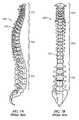
- the spine 100also known as the spinal column or vertebral column, supports the upper body, allows head, neck, and trunk motion, and includes twenty-four moveable vertebrae 101 including seven cervical vertebrae 102 , twelve thoracic vertebrae 104 , and five lumbar vertebrae 106 , which extend from the skull to the sacrum.
- each vertebra 101has a vertebral body 108 , a lamina 110 , a spinous process 112 , as well as facet structures 114 (which form facet joints), two transverse processes 116 , and two pedicles 118 , one on each side.
- Each individual vertebra 101has a large foramen 120 , which forms the spinal canal (not shown) when the vertebrae 101 are in their normal anatomical position forming the spine 100 .
- the spinal cord and major nerve fiber groupspass through and are protected by the spinal canal.
- a strong fibrous membrane, the dura materalso known as the dura, surrounds the spinal cord, nerve fibers, and fluid in the spinal canal.
- each pair of adjacent vertebrae 101 along with interconnecting soft tissues and an intervertebral disk 128constitutes a motion segment 122 , also known as a functional spinal unit, and the combined motions of many of such motion segments constitute overall spinal motion at any one time.
- the joining of two vertebrae 101also creates two neuroforaminae 124 , also known as intervertebral foraminae, one on each side, each of which is bordered by a facet joint 126 dorsally, a pedicle 118 superiorly, a pedicle 118 inferiorly, and an intervertebral disk 128 ventrally.
- Each neuroforamina 124allows passage of large nerve roots (not shown) and associated blood vessels (not shown).
- the intervertebral disk 128resides in the space between adjacent vertebral bodies, the intervertebral space 130 , also known as the interbody space or disk space.
- the level of each particular intervertebral space 130 and intervertebral disk 128is identified by naming the vertebrae 101 superior and inferior to it, for example L 4-5 in the case of the intervertebral space 130 and intervertebral disk 128 between the fourth and fifth lumbar vertebrae 106 .
- each intervertebral disk 128includes a collection of peripheral concentric rings comprised of strong ligaments known as annular ligaments 132 , also known as the annulus, and a softer central area of normally well hydrated material known as the nucleus 134 .
- the annular ligaments 132are arranged at different angles in alternate layers such that they provide support and stability, resisting excessive vertebral body 108 rotation and axial motion when proper tension is maintained.
- the nucleus 134is relatively incompressible in a young healthy spine, and thus its major role is to provide support and tension of the annular ligaments 132 to maintain stability while allowing a limited range of motion.
- the inferior surface of the vertebral body 108is concave (as shown in phantom), while the superior surfaces are flatter centrally and curl laterally to form the uncinate processes, which partially articulate with the inferior surface of the vertebral body of the adjacent superior vertebra.
- the cervical intervertebral space 130 and intervertebral disk 128are convex on the superior side but flatter on the inferior side. Cervical intervertebral disks are generally flatter and thinner than lumbar and thoracic intervertebral disks.
- Spine fusionis a process of growing bone between two or more adjacent vertebrae 101 such that the adjacent vertebrae 101 will move only in unison. This process involves placing bone, or material to guide or stimulate bone growth, in proximity to exposed bone of the vertebrae 101 , and then allowing time for new bone to grow and form a structurally strong connection, or fusion, between the vertebrae 101 .
- the earliest such procedurestook place approximately a century ago, and the procedures have developed over many years, including various attempts to fuse posterior structures of the spine such as the spinous process 112 , lamina 110 , facet joint 114 , and transverse processes 116 .
- intervertebral disk space 130has therefore become a major focus in interbody fusion surgery.
- the intervertebral disk space 130is cleaned as much as possible, and cartilage and abnormal surface bone, also known as endplate bone, from adjacent vertebral bodies 108 is removed, after which material is placed in the space to promote fusion.
- cartilage and abnormal surface bonealso known as endplate bone
- loose bone fragmentsdo not provide structural support and therefore fusion is often unsuccessful.
- Structural bone grafts from the patient or donorshave been successful, but may give rise to pain and complications if from the patient, and risk of disease transmission if from a donor.
- Vertebral defect devicesare increasingly used to assist with fusion between vertebral bodies 108 .
- Such devicesare intended to provide support to prevent excessive collapse of space between vertebrae 101 which could result in stenosis of the spinal canal or neuroforamina, progressive deformity, impairment or loss of nerve function, or pain.
- Such devicesalso provide at least one compartment to fill with bone, or material which assists in bone growth, in order to maintain close contact with vertebral bone as new bone is encouraged to bridge across the space involved.
- interbody devicescan be inserted from several directions (indicated by arrowed lines) including posterior interlaminar approaches on both sides A, B, transforaminal or partially lateral approaches C, D, anterior approaches E, and straight lateral approaches F.
- vertebral defect deviceshave proven useful in the lumbar or thoracic spine 104 , 106 , posterior and transforaminal placement (A, B, C, D) of any device is too dangerous in the cervical spine 102 .
- Some cylindrical bone grafts and deviceshave also been associated with increased subsidence and kyphotic deformities, particularly in the cervical area. Subsidence is the sinking of devices or structural bone grafts into adjacent vertebral bodies.
- Interbody deviceshave been constructed with polymers such as PEEK and carbon fiber/PEEK combinations. These devices have the advantage of minimal interference with future imaging studies whether by x-ray, CT scan, or MRI scan. Such devices usually have simple implanted metal markers in front and back to allow limited visualization of their position with x-rays or the like. Such devices are made with thick, vertically straight walls to provide support strength, but once they subside a small amount the straight walls offer no effective resistance to excessive subsidence. The surface area provided for fusion is also limited by the thick walls. Polymer material in current use does not allow construction of sharp edges and fixation elements and does not allow for varied shapes which might solve many of the problems with subsidence.
- an anterior plateIn the cervical spine 102 , it is known in the art that the addition of an anterior plate will limit subsidence and kyphotic deformity, but this adds cost and is not always successful. Complications such as backing out of fixation screws and screw and plate breakage have been significant problems. Anterior plates are difficult to install if more than two disk levels are fused, and may add to dysphagia. In addition, such a plate occupies much of the anterior surface of the superior and inferior vertebral bodies, and there is data to suggest that proximity of the plate to the adjacent disks promotes more rapid degenerative changes. If surgery is required at an adjacent level, it is almost always necessary to remove the plate to perform the surgery, which increases complexity and morbidity when further surgery is required.
- the deviceshould eliminate the need for ancillary stabilization devices such as anterior cervical plates and should be completely or nearly completely contained within the confines of the disk space.
- the deviceshould have excellent support strength, but limit the amount of interference with future imaging studies.
- the present inventionis directed to a cervical fixation device for insertion between a pair of adjacent cervical vertebrae.
- the cervical fixation deviceincludes a frame comprised of a first material.
- the framehas a generally rectangular proximal end and a generally rectangular distal end.
- the distal endis connected to the proximal end by at least one upper arch and at least one lower arch.
- the upper and lower archesare spaced apart from each other.
- the framehas a generally hollow interior, substantially open lateral sides between the upper and lower arches and a substantially open proximal end.
- the inventionis directed to a method of installing a cervical fixation device.
- the methodincludes the steps of: making an incision in an anterior region of a patient proximate a small gap between a first cervical vertebra and a second cervical vertebra of a spine of the patient, inserting a distal end of a surgical instrument and removing disk material from an intervertebral space between the first and second vertebrae, preparing the first and second vertebrae for fusion, inserting the cervical fixation device with protective covers into the intervertebral disk space such that the proximal end of the cervical fixation device is generally flush with an anterior edge of the first and second vertebrae, and removing the protective covers to expose an interior of the cervical fixation device and the at least one projection extending from the cervical fixation device.
- FIG. 1Ais right side rear perspective view of a first preferred embodiment of a cervical fixation device in accordance with the present invention
- FIG. 1Bis a right side rear perspective view of the cervical fixation device of FIG. 1A including an insert;
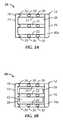
- FIG. 2Ais a right side elevation view of the cervical fixation device shown in FIG. 1A ;
- FIG. 2Bis a right side elevation view of the cervical fixation device shown in FIG. 1B ;
- FIG. 3Ais a top plan view of the cervical fixation device shown in FIG. 1A ;
- FIG. 3Bis a top plan view of the cervical fixation device shown in FIG. 1B ;
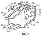
- FIG. 4is a right side rear perspective view of the cervical fixation device shown in FIG. 1B with attached protective covers;
- FIG. 5Ais a right side elevation view of a second preferred embodiment of a cervical fixation device in accordance with the present invention.
- FIG. 5Bis a right side elevation view of the cervical fixation device of FIG. 5A including an insert
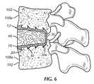
- FIG. 6is a left side cross sectional view of the cervical fixation device of FIG. 1A inserted into a vertebral disk space;
- FIG. 7Ais a right side elevation view of a human spinal column as is known in the art.
- FIG. 7Bis a front elevation view of a human spinal column as is known in the art.
- FIG. 8is a top plan view of a human vertebra as is known in the art.
- FIG. 9is a right side elevation view of a portion of the lumbar spine as is known in the art.
- FIG. 10is a top plan view of a lumbar vertebra as is known in the art.
- FIG. 11is a front view of a pair of cervical vertebrae as is known in the art.
- FIGS. 1A-5Ba cervical fixation device, generally designated 10 , 210 , in accordance with first and second preferred embodiments of the present invention for insertion between a pair of adjacent cervical vertebrae 102 .
- first and second preferred embodiments of the present inventionfor insertion between a pair of adjacent cervical vertebrae 102 .
- the description and method of the first preferred embodiment 10also applies to the second preferred embodiment 210 .
- the cervical fixation deviceincludes a frame 12 comprised of a first material.
- the frame 12is preferably formed from a machining process, and the least amount of the first material to provide adequate compressive strength and mechanical stability is used.
- the first materialis preferably a surgical grade titanium and is discernable by electromagnetic imaging, such as x-rays and computed tomography (CT) scans, but has minimal interference with magnetic resonance imaging (MRI) scans.
- CTcomputed tomography
- MRImagnetic resonance imaging
- the first materialmay be selected from the group consisting of a generally rigid biocompatible material such as machined bone graft, titanium, a nickel plated metal, a biocompatible alloy, a biocompatible ceramic, a biocompatible polymeric material or a biologically absorbable material. Though the above materials are preferred, any material allowing adequate support strength that could be machined, milled or otherwise formed into the shapes and features disclosed below and that would have minimal interference with imaging studies could be used without departing from the spirit and scope of the invention.
- the frame 12includes a generally rectangular proximal end 14 and a generally rectangular distal end 16 .
- a longitudinal axis of the frame 12extends from the proximal end 14 to the distal end 16 .
- the proximal end 14 and distal end 16may be rounded to form more of an oval or circular shape.
- the proximal end 14preferably includes flanges 18 vertically extending above and below the remainder of the frame 12 .
- the flanges 18preferably extend a minimal amount past the proximal end 14 in the vertical direction and preferably not in the lateral direction.
- the flanges 18do not extend laterally outwardly more than a maximum width of the cervical fixation device 10 , the lateral field of view is not obstructed during insertion of the cervical fixation device 10 .
- the flanges 18act as a stopper to prevent excessive distal placement or migration of the cervical fixation device 10 , to help eliminate the risk of spinal canal encroachment and to aid in fixation.
- the flanges 18abut the anterior edge of the cervical vertebrae 102 being fused together when the cervical fixation device 10 is installed as shown in FIG. 6 .
- the flanges 18may each include at least one projection 20 .
- the projections 20preferably point toward the distal end 16 of the cervical fixation device 10 in order to engage with the vertebrae 102 above and below the cervical fixation device 10 .
- the projections 20may be comprised of a plurality of distally pointing conical spikes as shown or may be an elongated edge extending at least partially along the flange 18 .
- the outer periphery of the flange 18may be sharpened, curved or pointed to form the projections 20 .
- the flanges 18 and the proximal end 14may be partially curved laterally with the convexity toward the proximal end 14 to match or better fit the contour or curve of the anterior leading edges of the adjacent vertebrae 102 once the vertebrae 102 are prepared for fixation.
- the flanges 18are preferably flush, or nearly flush, with the anterior edges of the vertebrae 102 above and below the cervical fixation device 10 so that there is minimal, if any, of the cervical fixation device 10 protruding anterior to the adjacent vertebrae.
- the distal end 16 of the cervical fixation device 10is connected to the proximal end 14 by at least one upper arch 22 and at least one lower arch 24 .
- the at least one upper arch 22is permanently attached to the at least one lower arch 24 by the proximal and distal ends 14 , 16 and both arches 22 , 24 extend from the proximal end 14 to the distal end 16 .
- the cervical fixation device 10includes three upper arches 22 and three lower arches 24 that are generally parallel and spaced apart. Between or proximate each arch 22 , 24 is a gap 28 configured to allow bone growth into the intervertebral space 130 .
- Four slots 26preferably extend through the flanges 18 , two spaced apart slots 26 for each flange 18 .
- the slots 26are generally aligned with the gaps 28 . Though three arches 22 , 24 and two gaps 28 are shown and described, it is within the spirit and scope of the invention that a single arch or planar segment with apertures of any geometry, or additional arches and gaps be used to connect the proximal and distal ends 14 , 16 .
- Each of the arches 22 , 24preferably includes at least one and preferably two partially sharpened projections 30 .
- the projections 30are preferably conically shaped and extend outwardly from the arches 22 , 24 and slant toward the proximal end 14 .
- the projections 30are preferably disposed at equally spaced intervals along each of the respective arches 22 , 24 .
- the top and bottom of the distal end of the cervical fixation device 10also preferably each include a sharpened edge 30 a .
- the sharpened edge 30 ais preferably a laterally extending edge that also slants toward the proximal end 14 .
- the sharpened edges 30 aextend both from the top and bottom of the distal end 16 .
- the sharpened edges 30 amay include receiving slots 30 b which are aligned with the gaps 28 .
- the sharpened edges 30 awith or without receiving slots 30 b , provide a smooth fit and transition to covers 46 (described below).
- the sharpened edge 30 a along with inserted covers 46allow for smooth insertion of the cervical fixation device 10 .
- the projections 30 and sharpened edge 30 aeach act as a barb and assist with securely retaining the cervical fixation device 10 in place between a pair of vertebrae 102 .
- the proximal slant of the projections 30 and sharpened edges 30 apenetrate into the bone of the adjacent vertebrae 102 to resist extrusion of the cervical fixation device 10 and provide rapid fixation and stabilization of the adjacent vertebrae 102 to promote fusion.
- the projections 30may have any shape such as an elongated triangle or edge and may or may not be included on each arch 22 , 24 . Any number of projections 30 may be made in any number of shapes, and in any number of arrangements, so long as the requisite retaining and fixation function is achieved, without departing from the spirit and scope of the invention.
- the frame 12has a generally hollow interior 32 and substantially open lateral sides between the upper and lower arches 22 , 24 .
- the proximal end 14is also substantially open.
- the generally hollow interior 32forms an open interior chamber that is generally defined by the shape of the frame 12 .
- the interior 32may house bone grafts or non-bone matter to aid in fusion of the adjacent vertebrae 102 .
- FIG. 6shows the inserted cervical fixation device 10 with bone 48 after healing.
- the frame 12preferably tapers from the proximal end 14 toward the distal end 16 between the upper and lower arches 22 , 24 such that the distance between the upper and lower arches 22 , 24 decreases from the proximal end 14 toward the distal end 16 .
- the height of the proximal end 14 as measured between the top and the bottomis greater than the height of the distal end 16 as measured between the top and the bottom to maintain lordotic angulation of the vertebral bodies above and below the cervical fixation device 10 . This results in a generally trapezoidal shape when viewed from the side, as shown in FIGS. 2A and 2B .
- the length of the frame 12 as measured between the proximal and distal ends 14 , 16is preferably between approximately 10 mm and 14 mm.
- the width of the frame 12 as measured between the lateral sides of the frame 12is preferably between approximately 10 mm to 14 mm.
- the height of the cervical fixation device as measured between the upper and lower arches 22 , 24is the height necessary to fit between vertebral bodies 108 which is approximately 5 mm to 12 mm for a single level. The height could be increased if more than one level is needed to partially replace a damaged vertebral body 108 .
- the distal end 16may include two or more generally spaced apart vertical members 36 , identical and generally parallel to each other for supporting the distal ends of the upper and lower arches 22 , 24 .
- each vertical member 36connects an upper arch 22 to a corresponding lower arch 24 .
- the distal end 16have a different configuration such as a solid wall, a plurality of apertures of any geometric shape or be entirely open.
- the cervical fixation device 10may also include an insert 38 .
- the insert 38is comprised of a second material.
- the second materialis preferably a radiotranslucent polymeric material such as PEEK.
- PEEKradiotranslucent polymeric material
- any biologically compatible polymer or other material which minimally interferes with imagingcould be used.
- the insert 38is positioned in the interior 32 of the frame 12 between the upper and lower arches 22 , 24 .
- the insert 38forms a trapezoid or box-shaped structure corresponding to the shape of the interior 32 .
- the insert 38is generally in the form of a square in top plan view and trapezoidal or rectangular in side view.
- the insert 38has an open central cavity 42 , a generally open top and bottom and a generally closed proximal and distal ends.
- the insert 38is disposed within at least a portion of the frame 12 and has lateral sides 40 exposed at least partially through the open lateral sides of the frame 12 .
- the lateral sides 40are generally flat with rounded or contoured edges on their surfaces.
- the lateral sides 40extend generally parallel with respect to each other, surround the central cavity 42 , and are preferably spaced apart along the outline of the shape which precisely complements the upper and lower arches 22 , 24 .
- Each lateral side 40contains at least one but preferably two generally circular side openings 44 which extend from the central cavity 42 through the lateral sides 40 to allow for bone growth between the central cavity 42 and the intervertebral space 130 .
- two generally circular openings 44are shown, it is understood that more or less than two openings of different shapes could be used without departing from the spirit and scope of the invention.
- the insert 38is preferably separately constructed from the frame 12 and then assembled by snap-fitting or press-fitting with suitable mating detents, grooves, edges or the like.
- the cervical fixation device 10could alternatively not include the insert 38 ( FIG. 6 ). Bone could alternatively be used in place of the insert 38 .
- Surgical bone screwscould be inserted through additional holes (not shown) and/or the slots 26 in the flange 18 to further secure the cervical fixation device 10 between the vertebral bodies in lieu of or in combination with the sharpened edges 20 .
- Other fastening devices or the likecould also be utilized.
- the cervical fixation device 10may include one or more protective covers 46 .
- the covers 46are inserted through the slots 26 in the flange 18 and cover the gaps 28 during insertion of the cervical fixation device 10 .
- the thickness of the covers 46is sufficient to limit the exposure of the projections 30 .
- the covers 46allow for smooth insertion by distracting the adjacent vertebrae 102 .
- the covers 46also prevent debris from entering the central cavity 42 or interior 32 during insertion of the cervical fixation device 10 and protect nearby anatomic structures, especially the adjacent vertebral bone surfaces, from injury by the projections 30 .
- the protective covers 46may curve outwardly as shown in FIG. 4 and in phantom in FIG. 2B . Additionally, the protective covers 46 may be part of or otherwise attached to the insertion tool such that the protective covers 46 are removed by or with the insertion tool.
- each of the protective covers 46is identical and is generally in the form of a smooth surfaced stick.
- the protective covers 46are of a thickness that matches the height of the projections 30 , 20 and sharpened edge 30 a so that preferably no sharp point or surface of the projections 30 , 20 or the sharpened edges 30 a protrudes beyond the smooth surface of the protective covers 46 .
- the sharpened edges 20may extend beyond the protective covers 46 so that they may be partially driven into the anterior margins of the adjacent vertebral bodies 108 .
- the covers 46extend through the slots 26 in the proximal end 14 .
- the insertion toolmay be formed of any substantially rigid material, but preferably is formed of titanium, hardened stainless steel, or a biocompatible alloy, composite, polymeric material or the like of sufficient strength. It should be noted that the material of construction of the insertion tool could be any material without diverging from the broad scope of the present invention.
- the protective covers 46are preferably made of a biocompatible polymer that is strong and somewhat flexible. However, other materials could be used, such as low density metal alloys, without departing from the spirit or scope of the invention.
- an incisionis made in an anterior region of a patient proximate a small gap between a first vertebra and a second vertebra 102 of a spine of the patient.
- Distraction pins(not shown) are inserted into the vertebral bodies 108 above and below the disk space 130 specified for fusion.
- a distal end of a surgical instrumentin inserted to remove disk material 128 from an intervertebral space 130 between the first and second vertebrae 102 .
- the adjacent vertebrae 102are then prepared for fusion, particularly proximate the anterior margins 108 a to accept the cervical fixation device 10 such that the cervical fixation device 10 does not protrude beyond the anterior vertebral margins 108 a .
- the intervertebral space 130may then be measured such that the appropriately sized cervical fixation device 10 is selected.
- the cervical fixation device 10 having the protective covers 46is inserted into the intervertebral space 130 between the first and second vertebrae 102 such that the proximal end 14 is generally flush with an anterior edge of the first and second vertebrae 102 .
- the protective covers 46are removed to expose an interior 42 of the cervical fixation device 10 and the at least one projection 30 extending from the cervical fixation device 10 .
- the at least one projection 20 , 30 and edges 30 aengage the bone to hold the cervical fixation device 10 in place.
- a solid bone graft or the insert 38 containing bone or non bone materialis inserted into the cervical fixation device 10 to promote fusion.
- the insert 38may be inserted before insertion of the frame 12 .
- a second preferred embodiment of the cervical fixation device 210includes generally parallel upper and lower arches 222 , 224 .
- the height of the proximal end 14 as measured between the top and the bottomis generally equal to the height of the distal end 16 as measured between the top and the bottom.
- the cervical fixation device 210 of the second preferred embodimentis nearly identical to the first embodiment of the cervical fixation device 10 except that the upper and lower arches 222 , 224 form a generally rectangular shape when viewed from the side. Similar numbers indicate similar elements as discussed above for the first embodiment. A discussion of the similar features has been eliminated for convenience only and is not limiting.
Landscapes
- Health & Medical Sciences (AREA)
- Engineering & Computer Science (AREA)
- Biomedical Technology (AREA)
- Neurology (AREA)
- Orthopedic Medicine & Surgery (AREA)
- Cardiology (AREA)
- Oral & Maxillofacial Surgery (AREA)
- Transplantation (AREA)
- Heart & Thoracic Surgery (AREA)
- Vascular Medicine (AREA)
- Life Sciences & Earth Sciences (AREA)
- Animal Behavior & Ethology (AREA)
- General Health & Medical Sciences (AREA)
- Public Health (AREA)
- Veterinary Medicine (AREA)
- Prostheses (AREA)
- Surgical Instruments (AREA)
Abstract
Description
Claims (12)
Priority Applications (1)
| Application Number | Priority Date | Filing Date | Title |
|---|---|---|---|
| US11/741,200US7871441B2 (en) | 2006-04-28 | 2007-04-27 | Cervical fixation device |
Applications Claiming Priority (2)
| Application Number | Priority Date | Filing Date | Title |
|---|---|---|---|
| US74589506P | 2006-04-28 | 2006-04-28 | |
| US11/741,200US7871441B2 (en) | 2006-04-28 | 2007-04-27 | Cervical fixation device |
Publications (2)
| Publication Number | Publication Date |
|---|---|
| US20080015581A1 US20080015581A1 (en) | 2008-01-17 |
| US7871441B2true US7871441B2 (en) | 2011-01-18 |
Family
ID=38372453
Family Applications (2)
| Application Number | Title | Priority Date | Filing Date |
|---|---|---|---|
| US11/741,446Expired - Fee RelatedUS8353962B2 (en) | 2006-04-28 | 2007-04-27 | Dual composition vertebral defect device |
| US11/741,200Expired - Fee RelatedUS7871441B2 (en) | 2006-04-28 | 2007-04-27 | Cervical fixation device |
Family Applications Before (1)
| Application Number | Title | Priority Date | Filing Date |
|---|---|---|---|
| US11/741,446Expired - Fee RelatedUS8353962B2 (en) | 2006-04-28 | 2007-04-27 | Dual composition vertebral defect device |
Country Status (4)
| Country | Link |
|---|---|
| US (2) | US8353962B2 (en) |
| EP (2) | EP2085056A3 (en) |
| AT (1) | ATE444041T1 (en) |
| DE (1) | DE602007002583D1 (en) |
Cited By (37)
| Publication number | Priority date | Publication date | Assignee | Title |
|---|---|---|---|---|
| US20050197706A1 (en)* | 2004-02-04 | 2005-09-08 | Ldr Medical, Inc. | Intervertebral disc prosthesis |
| US20080200984A1 (en)* | 2007-02-16 | 2008-08-21 | Ldr Medical | Intervertebral Disc Prosthesis Insertion Assemblies |
| US20080269902A1 (en)* | 2007-04-27 | 2008-10-30 | Baynham Bret O | Cervical implant |
| US20090132054A1 (en)* | 2004-12-22 | 2009-05-21 | Ldr Medical | Intervertebral Disc Prosthesis |
| US20090138083A1 (en)* | 2006-09-14 | 2009-05-28 | Ashok Biyani | Variable height vertebral body replacement implant |
| US20110040384A1 (en)* | 2009-08-14 | 2011-02-17 | Junn Fredrick S | Implantable prosthetic cage |
| US20110077739A1 (en)* | 2005-09-23 | 2011-03-31 | Ldr Medical | Intervertebral disc prosthesis |
| US8267999B2 (en) | 2002-11-05 | 2012-09-18 | Ldr Medical | Intervertebral disc prosthesis |
| US8343219B2 (en) | 2007-06-08 | 2013-01-01 | Ldr Medical | Intersomatic cage, intervertebral prosthesis, anchoring device and implantation instruments |
| US20140094919A1 (en)* | 2012-10-01 | 2014-04-03 | Kaustubh Mantri | Interbody fusion implant |
| US8771284B2 (en) | 2005-11-30 | 2014-07-08 | Ldr Medical | Intervertebral disc prosthesis and instrumentation for insertion of the prosthesis between the vertebrae |
| US8974532B2 (en) | 2004-04-28 | 2015-03-10 | Ldr Medical | Intervertebral disc prosthesis |
| US20150142114A1 (en)* | 2013-11-21 | 2015-05-21 | Perumala Corporation | Intervertebral Disk Cage and Stabilizer |
| US9039774B2 (en) | 2012-02-24 | 2015-05-26 | Ldr Medical | Anchoring device and system for an intervertebral implant, intervertebral implant and implantation instrument |
| US9039768B2 (en) | 2006-12-22 | 2015-05-26 | Medos International Sarl | Composite vertebral spacers and instrument |
| US9044337B2 (en) | 2009-12-31 | 2015-06-02 | Ldr Medical | Anchoring device and system for an intervertebral implant, intervertebral implant and implantation instrument |
| US9078765B2 (en) | 2001-07-13 | 2015-07-14 | Ldr Medical | Vertebral cage device with modular fixation |
| US9119728B2 (en) | 2011-01-17 | 2015-09-01 | Cibor, Inc. | Reinforced carbon fiber/carbon foam intervertebral spine fusion device |
| US9333095B2 (en) | 2001-05-04 | 2016-05-10 | Ldr Medical | Intervertebral disc prosthesis, surgical methods, and fitting tools |
| US9463091B2 (en) | 2009-09-17 | 2016-10-11 | Ldr Medical | Intervertebral implant having extendable bone fixation members |
| US20170119537A1 (en)* | 2015-05-13 | 2017-05-04 | Gil Tepper | Three column spinal fixation implants and associated surgical methods |
| US9662225B2 (en) | 2012-03-06 | 2017-05-30 | DePuy Synthes Products, Inc. | Nubbed plate |
| US9687354B2 (en) | 2008-03-26 | 2017-06-27 | DePuy Synthes Products, Inc. | Posterior intervertebral disc inserter and expansion techniques |
| US9713535B2 (en) | 2006-02-15 | 2017-07-25 | Ldr Medical | Transforaminal intersomatic cage for an intervertebral fusion graft and an instrument for implanting the cage |
| US9877842B2 (en) | 2014-01-30 | 2018-01-30 | Ldr Medical | Anchoring device for a spinal implant, spinal implant and implantation instrumentation |
| US9937050B2 (en) | 2013-05-16 | 2018-04-10 | Ldr Medical | Vertebral implant, vertebral fastening device of the implant and implant instrumentation |
| US10182921B2 (en) | 2012-11-09 | 2019-01-22 | DePuy Synthes Products, Inc. | Interbody device with opening to allow packing graft and other biologics |
| US10335289B2 (en) | 2010-09-23 | 2019-07-02 | DePuy Synthes Products, Inc. | Stand alone intervertebral fusion device |
| US10369015B2 (en) | 2010-09-23 | 2019-08-06 | DePuy Synthes Products, Inc. | Implant inserter having a laterally-extending dovetail engagement feature |
| US10478310B2 (en) | 2014-05-06 | 2019-11-19 | Ldr Medical, S.A.S. | Vertebral implant, device for vertebral attachment of the implant and instrumentation for implantation thereof |
| US10500062B2 (en) | 2009-12-10 | 2019-12-10 | DePuy Synthes Products, Inc. | Bellows-like expandable interbody fusion cage |
| US10603185B2 (en) | 2004-02-04 | 2020-03-31 | Ldr Medical | Intervertebral disc prosthesis |
| US10624758B2 (en) | 2009-03-30 | 2020-04-21 | DePuy Synthes Products, Inc. | Zero profile spinal fusion cage |
| US10940016B2 (en) | 2017-07-05 | 2021-03-09 | Medos International Sarl | Expandable intervertebral fusion cage |
| US11291479B2 (en) | 2020-02-12 | 2022-04-05 | Blue Sky Technologies, LLC | Surgical fastener |
| US11529241B2 (en) | 2010-09-23 | 2022-12-20 | DePuy Synthes Products, Inc. | Fusion cage with in-line single piece fixation |
| US11628057B2 (en)* | 2017-08-28 | 2023-04-18 | Conmed Corporation | System and method for preparing a soft tissue graft |
Families Citing this family (47)
| Publication number | Priority date | Publication date | Assignee | Title |
|---|---|---|---|---|
| US7105023B2 (en)* | 2002-01-17 | 2006-09-12 | Concept Matrix, L.L.C. | Vertebral defect device |
| US8137402B2 (en)* | 2002-01-17 | 2012-03-20 | Concept Matrix Llc | Vertebral defect device |
| ES2335931T3 (en)* | 2006-09-27 | 2010-04-06 | K2M, Inc. | SPACER BETWEEN VERTEBRAL BODIES. |
| US20080161929A1 (en) | 2006-12-29 | 2008-07-03 | Mccormack Bruce | Cervical distraction device |
| WO2009089367A2 (en) | 2008-01-09 | 2009-07-16 | Providence Medical Technology, Inc. | Methods and apparatus for accessing and treating the facet joint |
| WO2009100400A1 (en)* | 2008-02-06 | 2009-08-13 | Nuvasive, Inc. | Systems and methods for spinal fusion |
| EP2361046B1 (en) | 2008-06-06 | 2019-04-24 | Providence Medical Technology, Inc. | Cervical distraction/implant delivery device |
| US8361152B2 (en) | 2008-06-06 | 2013-01-29 | Providence Medical Technology, Inc. | Facet joint implants and delivery tools |
| US11224521B2 (en) | 2008-06-06 | 2022-01-18 | Providence Medical Technology, Inc. | Cervical distraction/implant delivery device |
| US8267966B2 (en) | 2008-06-06 | 2012-09-18 | Providence Medical Technology, Inc. | Facet joint implants and delivery tools |
| US9333086B2 (en) | 2008-06-06 | 2016-05-10 | Providence Medical Technology, Inc. | Spinal facet cage implant |
| CA2725811A1 (en) | 2008-06-06 | 2009-12-10 | Providence Medical Technology, Inc. | Facet joint implants and delivery tools |
| US9381049B2 (en) | 2008-06-06 | 2016-07-05 | Providence Medical Technology, Inc. | Composite spinal facet implant with textured surfaces |
| USD853560S1 (en) | 2008-10-09 | 2019-07-09 | Nuvasive, Inc. | Spinal implant insertion device |
| US9358122B2 (en) | 2011-01-07 | 2016-06-07 | K2M, Inc. | Interbody spacer |
| US9132021B2 (en) | 2011-10-07 | 2015-09-15 | Pioneer Surgical Technology, Inc. | Intervertebral implant |
| US9655746B2 (en)* | 2011-11-09 | 2017-05-23 | Globus Medical, Inc. | Intervertebral spinal implant |
| US8795167B2 (en) | 2011-11-15 | 2014-08-05 | Baxano Surgical, Inc. | Spinal therapy lateral approach access instruments |
| RU2482818C1 (en)* | 2012-01-11 | 2013-05-27 | Государственное автономное учреждение здравоохранения "Республиканская клиническая больница Министерства здравоохранения Республики Татарстан" | Universal prosthesis of vertebra body for treatment of fracture-dislocations and stabilisation of cervical spine and method of vertebra dislocation reposition with application of said device |
| US9717603B2 (en) | 2012-02-17 | 2017-08-01 | Timothy T. DAVIS | Implantable facet fusion devices |
| USD732667S1 (en) | 2012-10-23 | 2015-06-23 | Providence Medical Technology, Inc. | Cage spinal implant |
| USD745156S1 (en) | 2012-10-23 | 2015-12-08 | Providence Medical Technology, Inc. | Spinal implant |
| RU2541823C1 (en)* | 2014-01-10 | 2015-02-20 | Государственное автономное учреждение здравоохранения "Республиканская клиническая больница Министерства здравоохранения Республики Татарстан" | Device for correction of displaced cervical articular process positions and method for using it |
| AU2015267055B2 (en) | 2014-05-27 | 2020-04-02 | Christopher U. Phan | Lateral mass fixation implant |
| JP2017520357A (en) | 2014-05-28 | 2017-07-27 | プロビデンス メディカル テクノロジー インコーポレイテッド | Outer mass fixing system |
| US10117752B2 (en) | 2015-02-26 | 2018-11-06 | Uncinate Joint, Llc | Uncinate joint stabilizers and associated systems and methods |
| CN108289689A (en) | 2015-10-13 | 2018-07-17 | 普罗维登斯医疗技术公司 | Joint of vertebral column implantation material conveying device and system |
| USD841165S1 (en) | 2015-10-13 | 2019-02-19 | Providence Medical Technology, Inc. | Cervical cage |
| TW201806562A (en) | 2016-06-28 | 2018-03-01 | 普羅維登斯醫療科技公司 | Spinal implant and methods of using the same |
| USD887552S1 (en) | 2016-07-01 | 2020-06-16 | Providence Medical Technology, Inc. | Cervical cage |
| US10265189B2 (en) | 2016-09-13 | 2019-04-23 | Warsaw Orthopedic, Inc. | Interbody spinal fusion device |
| US11871968B2 (en) | 2017-05-19 | 2024-01-16 | Providence Medical Technology, Inc. | Spinal fixation access and delivery system |
| US11051857B2 (en) | 2017-08-10 | 2021-07-06 | Ortho Development Corporation | Tether clamping assemblies and related methods and apparatus |
| US11071569B2 (en) | 2017-08-10 | 2021-07-27 | Ortho Development Corporation | Nesting tether clamping assemblies and related methods and apparatus |
| WO2019051260A1 (en) | 2017-09-08 | 2019-03-14 | Pioneer Surgical Technology, Inc. | Intervertebral implants, instruments, and methods |
| USD907771S1 (en) | 2017-10-09 | 2021-01-12 | Pioneer Surgical Technology, Inc. | Intervertebral implant |
| US11766339B1 (en) | 2017-10-24 | 2023-09-26 | Omnia Medical, LLC | Multi-material multi-component spinal implant |
| US10736752B1 (en) | 2017-10-24 | 2020-08-11 | Omnia Medical, LLC | Multi-material multi-component spinal implant |
| US10575962B2 (en)* | 2017-11-20 | 2020-03-03 | Warsaw Orthopedic, Inc. | Spinal implant |
| US11648128B2 (en) | 2018-01-04 | 2023-05-16 | Providence Medical Technology, Inc. | Facet screw and delivery device |
| WO2020061464A1 (en) | 2018-09-21 | 2020-03-26 | Providence Medical Technology, Inc. | Vertebral joint access and decortication devices and methods of using |
| USD933230S1 (en) | 2019-04-15 | 2021-10-12 | Providence Medical Technology, Inc. | Cervical cage |
| WO2020231929A1 (en)* | 2019-05-10 | 2020-11-19 | A.I. Spine LLC | Electromagnetic spinal cage |
| USD911525S1 (en) | 2019-06-21 | 2021-02-23 | Providence Medical Technology, Inc. | Spinal cage |
| US11819255B2 (en) | 2019-10-07 | 2023-11-21 | Ortho Development Corporation | Tether tensioning instrumentation and related methods |
| USD945621S1 (en) | 2020-02-27 | 2022-03-08 | Providence Medical Technology, Inc. | Spinal cage |
| US11166825B1 (en) | 2020-07-01 | 2021-11-09 | Warsaw Orthopedic, Inc. | Spinal implant |
Citations (64)
| Publication number | Priority date | Publication date | Assignee | Title |
|---|---|---|---|---|
| US4349921A (en) | 1980-06-13 | 1982-09-21 | Kuntz J David | Intervertebral disc prosthesis |
| US4545374A (en) | 1982-09-03 | 1985-10-08 | Jacobson Robert E | Method and instruments for performing a percutaneous lumbar diskectomy |
| SU1424826A1 (en) | 1986-05-22 | 1988-09-23 | Белорусский научно-исследовательский институт травматологии и ортопедии | Fixative for spinal column |
| US4936848A (en) | 1989-09-22 | 1990-06-26 | Bagby George W | Implant for vertebrae |
| US4961740A (en) | 1988-10-17 | 1990-10-09 | Surgical Dynamics, Inc. | V-thread fusion cage and method of fusing a bone joint |
| US5258031A (en) | 1992-01-06 | 1993-11-02 | Danek Medical | Intervertebral disk arthroplasty |
| US5425773A (en) | 1992-01-06 | 1995-06-20 | Danek Medical, Inc. | Intervertebral disk arthroplasty device |
| US5522899A (en) | 1988-06-28 | 1996-06-04 | Sofamor Danek Properties, Inc. | Artificial spinal fusion implants |
| US5549679A (en) | 1994-05-20 | 1996-08-27 | Kuslich; Stephen D. | Expandable fabric implant for stabilizing the spinal motion segment |
| WO1996040014A1 (en) | 1995-06-07 | 1996-12-19 | Sdgi Holdings, Inc. | Reinforced porous spinal implants |
| USD377095S (en) | 1994-06-03 | 1996-12-31 | Sofamor Danek Properties, Inc. | Interbody spinal implant |
| USD377096S (en) | 1994-06-03 | 1996-12-31 | Sofamor Danek Properties, Inc. | Interbody spinal implant |
| US5593409A (en) | 1988-06-13 | 1997-01-14 | Sofamor Danek Group, Inc. | Interbody spinal fusion implants |
| USD377527S (en) | 1994-06-03 | 1997-01-21 | Sofamor Danek Group, Inc. | Artificial spinal infusion implant |
| US5607424A (en)* | 1995-04-10 | 1997-03-04 | Tropiano; Patrick | Domed cage |
| US5609636A (en) | 1994-05-23 | 1997-03-11 | Spine-Tech, Inc. | Spinal implant |
| WO1997014377A1 (en) | 1995-10-16 | 1997-04-24 | Sdgi Holdings, Inc. | Intervertebral spacer |
| US5645596A (en) | 1993-07-07 | 1997-07-08 | Asahi Kogaku Kogyo Kabushiki Kaisha | Ceramic vertebrae prosthesis |
| US5653761A (en) | 1994-03-18 | 1997-08-05 | Pisharodi; Madhavan | Method of lumbar intervertebral disk stabilization |
| US5669909A (en) | 1995-03-27 | 1997-09-23 | Danek Medical, Inc. | Interbody fusion device and method for restoration of normal spinal anatomy |
| US5674296A (en) | 1994-11-14 | 1997-10-07 | Spinal Dynamics Corporation | Human spinal disc prosthesis |
| WO1997037620A1 (en) | 1996-04-03 | 1997-10-16 | Scient'x S.A.R.L. | Intersomatic setting and fusion system |
| US5888226A (en) | 1997-11-12 | 1999-03-30 | Rogozinski; Chaim | Intervertebral prosthetic disc |
| WO1999032054A1 (en) | 1997-12-19 | 1999-07-01 | Sofamor Danek Holdings, Inc. | Partial discal prosthesis |
| US5980522A (en) | 1994-07-22 | 1999-11-09 | Koros; Tibor | Expandable spinal implants |
| US6039762A (en) | 1995-06-07 | 2000-03-21 | Sdgi Holdings, Inc. | Reinforced bone graft substitutes |
| USD425989S (en) | 1996-07-15 | 2000-05-30 | Sofamor Danek Holdings, Inc. | Artificial spinal fusion implant |
| US6102950A (en) | 1999-01-19 | 2000-08-15 | Vaccaro; Alex | Intervertebral body fusion device |
| US6113637A (en) | 1998-10-22 | 2000-09-05 | Sofamor Danek Holdings, Inc. | Artificial intervertebral joint permitting translational and rotational motion |
| US6126688A (en) | 1998-12-21 | 2000-10-03 | Surgical Dynamics Inc. | Apparatus for fusion of adjacent bone structures |
| US6136031A (en) | 1998-06-17 | 2000-10-24 | Surgical Dynamics, Inc. | Artificial intervertebral disc |
| FR2794967A1 (en) | 1999-06-21 | 2000-12-22 | Medicrea | Dilating device for insertion in bone joints, useful for joints affected by degenerative tissue disease, is shaped like a cone designed to fill the biconcave joint cavity |
| US6174334B1 (en) | 1998-12-16 | 2001-01-16 | Loubert Suddaby | Expandable intervertebral fusion implant and applicator |
| US6193757B1 (en)* | 1998-10-29 | 2001-02-27 | Sdgi Holdings, Inc. | Expandable intervertebral spacers |
| US6231610B1 (en) | 1999-08-25 | 2001-05-15 | Allegiance Corporation | Anterior cervical column support device |
| US6245108B1 (en) | 1999-02-25 | 2001-06-12 | Spineco | Spinal fusion implant |
| US6270528B1 (en) | 1998-08-06 | 2001-08-07 | Sdgi Holdings, Inc. | Composited intervertebral bone spacers |
| US20010018614A1 (en) | 1999-03-16 | 2001-08-30 | Bianchi John R. | Implants for orthopedic applications |
| US6309421B1 (en) | 1994-03-18 | 2001-10-30 | Madhavan Pisharodi | Rotating, locking intervertebral disk stabilizer and applicator |
| US6419705B1 (en) | 1999-06-23 | 2002-07-16 | Sulzer Spine-Tech Inc. | Expandable fusion device and method |
| US6425920B1 (en) | 1999-10-13 | 2002-07-30 | James S. Hamada | Spinal fusion implant |
| US20020116009A1 (en) | 2000-05-08 | 2002-08-22 | Fraser Robert D. | Medical installation tool |
| US6454805B1 (en) | 1998-09-04 | 2002-09-24 | Dimso (Distribution Medicale Du Sud-Ouest) | Interbody cavity implant, in particular for cervical vertebrae |
| WO2002080818A1 (en) | 2001-04-05 | 2002-10-17 | Waldemar Link (Gmbh & Co.) | System for intervertebral disk prostheses |
| US6468311B2 (en) | 2001-01-22 | 2002-10-22 | Sdgi Holdings, Inc. | Modular interbody fusion implant |
| US20030004576A1 (en) | 2001-06-28 | 2003-01-02 | Thalgott John S. | Modular anatomic fusion device |
| US6520991B2 (en) | 1999-05-11 | 2003-02-18 | Donald R. Huene | Expandable implant for inter-vertebral stabilization, and a method of stabilizing vertebrae |
| US6527803B1 (en) | 1998-06-23 | 2003-03-04 | Dimso (Distribution Medicale Du Sud-Ouest) | Intersomatic spine implant having anchoring elements |
| US6582433B2 (en) | 2001-04-09 | 2003-06-24 | St. Francis Medical Technologies, Inc. | Spine fixation device and method |
| US6648917B2 (en) | 2001-10-17 | 2003-11-18 | Medicinelodge, Inc. | Adjustable bone fusion implant and method |
| EP1112753B1 (en) | 1999-12-30 | 2004-07-14 | Bioprofile | Mobile implant for interposition between two osseous surfaces |
| US20040199251A1 (en) | 2003-04-01 | 2004-10-07 | Sdgi Holdings, Inc. | Interbody fusion device |
| US20040254644A1 (en) | 2002-10-21 | 2004-12-16 | Taylor Brett Allison | Intervertebral disk prosthesis |
| US20050004672A1 (en)* | 1995-10-16 | 2005-01-06 | John Pafford | Bone grafts |
| US20050010290A1 (en) | 2003-06-26 | 2005-01-13 | Hawkins John R. | Dual durometer elastomer artificial disc |
| US6855168B2 (en) | 1997-04-25 | 2005-02-15 | Stryker France | Intersomatic implants in two parts |
| US20050131539A1 (en)* | 1998-03-20 | 2005-06-16 | Zimmer Spine, Inc. | Intervertebral implant with reduced contact area and method |
| US7044972B2 (en)* | 2001-01-30 | 2006-05-16 | Synthes Ag Chur | Bone implant, in particular, an inter-vertebral implant |
| US20060206208A1 (en) | 1999-05-05 | 2006-09-14 | Sdgi Holdings, Inc. | Push-in interbody spinal fusion implant with multi-lock for locking opposed screws and method for use thereof |
| US7137997B2 (en)* | 2003-12-29 | 2006-11-21 | Globus Medical, Inc. | Spinal fusion implant |
| US20070038545A1 (en) | 2004-08-20 | 2007-02-15 | Smith Eric S | Facilitating management of 401K retirement savings plans |
| WO2007038545A1 (en) | 2005-09-26 | 2007-04-05 | Warsaw Orthopedic, Inc. | Transforaminal hybrid implant |
| US20070233247A1 (en)* | 2005-09-26 | 2007-10-04 | Schwab Frank J | Hybrid intervertebral spinal fusion implant |
| US7503933B2 (en)* | 1995-06-07 | 2009-03-17 | Warsaw Orthopedic, Inc. | Lordotic interbody spinal fusion implants |
Family Cites Families (1)
| Publication number | Priority date | Publication date | Assignee | Title |
|---|---|---|---|---|
| FR2822674B1 (en) | 2001-04-03 | 2003-06-27 | Scient X | STABILIZED INTERSOMATIC MELTING SYSTEM FOR VERTEBERS |
- 2007
- 2007-04-27USUS11/741,446patent/US8353962B2/ennot_activeExpired - Fee Related
- 2007-04-27ATAT07008690Tpatent/ATE444041T1/ennot_activeIP Right Cessation
- 2007-04-27EPEP09005645Apatent/EP2085056A3/ennot_activeWithdrawn
- 2007-04-27EPEP07008690Apatent/EP1849437B1/ennot_activeNot-in-force
- 2007-04-27DEDE602007002583Tpatent/DE602007002583D1/enactiveActive
- 2007-04-27USUS11/741,200patent/US7871441B2/ennot_activeExpired - Fee Related
Patent Citations (77)
| Publication number | Priority date | Publication date | Assignee | Title |
|---|---|---|---|---|
| US4349921A (en) | 1980-06-13 | 1982-09-21 | Kuntz J David | Intervertebral disc prosthesis |
| US4545374A (en) | 1982-09-03 | 1985-10-08 | Jacobson Robert E | Method and instruments for performing a percutaneous lumbar diskectomy |
| SU1424826A1 (en) | 1986-05-22 | 1988-09-23 | Белорусский научно-исследовательский институт травматологии и ортопедии | Fixative for spinal column |
| US5785710A (en) | 1988-06-13 | 1998-07-28 | Sofamor Danek Group, Inc. | Interbody spinal fusion implants |
| US5593409A (en) | 1988-06-13 | 1997-01-14 | Sofamor Danek Group, Inc. | Interbody spinal fusion implants |
| US6478823B1 (en) | 1988-06-28 | 2002-11-12 | Sofamor Danek Holdings, Inc. | Artificial spinal fusion implants |
| US5522899A (en) | 1988-06-28 | 1996-06-04 | Sofamor Danek Properties, Inc. | Artificial spinal fusion implants |
| US5776199A (en) | 1988-06-28 | 1998-07-07 | Sofamor Danek Properties | Artificial spinal fusion implants |
| US6447547B1 (en) | 1988-06-28 | 2002-09-10 | Sofamor Danek Group, Inc. | Artificial spinal fusion implants |
| US4961740A (en) | 1988-10-17 | 1990-10-09 | Surgical Dynamics, Inc. | V-thread fusion cage and method of fusing a bone joint |
| US4961740B1 (en) | 1988-10-17 | 1997-01-14 | Surgical Dynamics Inc | V-thread fusion cage and method of fusing a bone joint |
| US4936848A (en) | 1989-09-22 | 1990-06-26 | Bagby George W | Implant for vertebrae |
| US5425773A (en) | 1992-01-06 | 1995-06-20 | Danek Medical, Inc. | Intervertebral disk arthroplasty device |
| US5562738A (en) | 1992-01-06 | 1996-10-08 | Danek Medical, Inc. | Intervertebral disk arthroplasty device |
| US5258031A (en) | 1992-01-06 | 1993-11-02 | Danek Medical | Intervertebral disk arthroplasty |
| US5645596A (en) | 1993-07-07 | 1997-07-08 | Asahi Kogaku Kogyo Kabushiki Kaisha | Ceramic vertebrae prosthesis |
| US6309421B1 (en) | 1994-03-18 | 2001-10-30 | Madhavan Pisharodi | Rotating, locking intervertebral disk stabilizer and applicator |
| US5653761A (en) | 1994-03-18 | 1997-08-05 | Pisharodi; Madhavan | Method of lumbar intervertebral disk stabilization |
| US5549679A (en) | 1994-05-20 | 1996-08-27 | Kuslich; Stephen D. | Expandable fabric implant for stabilizing the spinal motion segment |
| US5571189A (en) | 1994-05-20 | 1996-11-05 | Kuslich; Stephen D. | Expandable fabric implant for stabilizing the spinal motion segment |
| US5609636A (en) | 1994-05-23 | 1997-03-11 | Spine-Tech, Inc. | Spinal implant |
| USD377096S (en) | 1994-06-03 | 1996-12-31 | Sofamor Danek Properties, Inc. | Interbody spinal implant |
| USD377095S (en) | 1994-06-03 | 1996-12-31 | Sofamor Danek Properties, Inc. | Interbody spinal implant |
| USD377527S (en) | 1994-06-03 | 1997-01-21 | Sofamor Danek Group, Inc. | Artificial spinal infusion implant |
| US5980522A (en) | 1994-07-22 | 1999-11-09 | Koros; Tibor | Expandable spinal implants |
| US5674296A (en) | 1994-11-14 | 1997-10-07 | Spinal Dynamics Corporation | Human spinal disc prosthesis |
| US5669909A (en) | 1995-03-27 | 1997-09-23 | Danek Medical, Inc. | Interbody fusion device and method for restoration of normal spinal anatomy |
| US5984967A (en) | 1995-03-27 | 1999-11-16 | Sdgi Holdings, Inc. | Osteogenic fusion devices |
| US5607424A (en)* | 1995-04-10 | 1997-03-04 | Tropiano; Patrick | Domed cage |
| US5702449A (en) | 1995-06-07 | 1997-12-30 | Danek Medical, Inc. | Reinforced porous spinal implants |
| WO1996040014A1 (en) | 1995-06-07 | 1996-12-19 | Sdgi Holdings, Inc. | Reinforced porous spinal implants |
| US6039762A (en) | 1995-06-07 | 2000-03-21 | Sdgi Holdings, Inc. | Reinforced bone graft substitutes |
| US7503933B2 (en)* | 1995-06-07 | 2009-03-17 | Warsaw Orthopedic, Inc. | Lordotic interbody spinal fusion implants |
| WO1997014377A1 (en) | 1995-10-16 | 1997-04-24 | Sdgi Holdings, Inc. | Intervertebral spacer |
| US20050004672A1 (en)* | 1995-10-16 | 2005-01-06 | John Pafford | Bone grafts |
| WO1997037620A1 (en) | 1996-04-03 | 1997-10-16 | Scient'x S.A.R.L. | Intersomatic setting and fusion system |
| US6235059B1 (en) | 1996-04-03 | 2001-05-22 | Scient'x (Societe A Responsabilite Limitee) | Intersomatic setting and fusion system |
| USD425989S (en) | 1996-07-15 | 2000-05-30 | Sofamor Danek Holdings, Inc. | Artificial spinal fusion implant |
| US6855168B2 (en) | 1997-04-25 | 2005-02-15 | Stryker France | Intersomatic implants in two parts |
| US5888226A (en) | 1997-11-12 | 1999-03-30 | Rogozinski; Chaim | Intervertebral prosthetic disc |
| WO1999032054A1 (en) | 1997-12-19 | 1999-07-01 | Sofamor Danek Holdings, Inc. | Partial discal prosthesis |
| US20050131539A1 (en)* | 1998-03-20 | 2005-06-16 | Zimmer Spine, Inc. | Intervertebral implant with reduced contact area and method |
| US6136031A (en) | 1998-06-17 | 2000-10-24 | Surgical Dynamics, Inc. | Artificial intervertebral disc |
| US6527803B1 (en) | 1998-06-23 | 2003-03-04 | Dimso (Distribution Medicale Du Sud-Ouest) | Intersomatic spine implant having anchoring elements |
| US6270528B1 (en) | 1998-08-06 | 2001-08-07 | Sdgi Holdings, Inc. | Composited intervertebral bone spacers |
| US6454805B1 (en) | 1998-09-04 | 2002-09-24 | Dimso (Distribution Medicale Du Sud-Ouest) | Interbody cavity implant, in particular for cervical vertebrae |
| US6113637A (en) | 1998-10-22 | 2000-09-05 | Sofamor Danek Holdings, Inc. | Artificial intervertebral joint permitting translational and rotational motion |
| US6193757B1 (en)* | 1998-10-29 | 2001-02-27 | Sdgi Holdings, Inc. | Expandable intervertebral spacers |
| US6174334B1 (en) | 1998-12-16 | 2001-01-16 | Loubert Suddaby | Expandable intervertebral fusion implant and applicator |
| US6126688A (en) | 1998-12-21 | 2000-10-03 | Surgical Dynamics Inc. | Apparatus for fusion of adjacent bone structures |
| US6102950A (en) | 1999-01-19 | 2000-08-15 | Vaccaro; Alex | Intervertebral body fusion device |
| US6245108B1 (en) | 1999-02-25 | 2001-06-12 | Spineco | Spinal fusion implant |
| US20010018614A1 (en) | 1999-03-16 | 2001-08-30 | Bianchi John R. | Implants for orthopedic applications |
| US20060206208A1 (en) | 1999-05-05 | 2006-09-14 | Sdgi Holdings, Inc. | Push-in interbody spinal fusion implant with multi-lock for locking opposed screws and method for use thereof |
| US6520991B2 (en) | 1999-05-11 | 2003-02-18 | Donald R. Huene | Expandable implant for inter-vertebral stabilization, and a method of stabilizing vertebrae |
| FR2794967A1 (en) | 1999-06-21 | 2000-12-22 | Medicrea | Dilating device for insertion in bone joints, useful for joints affected by degenerative tissue disease, is shaped like a cone designed to fill the biconcave joint cavity |
| US6419705B1 (en) | 1999-06-23 | 2002-07-16 | Sulzer Spine-Tech Inc. | Expandable fusion device and method |
| US6231610B1 (en) | 1999-08-25 | 2001-05-15 | Allegiance Corporation | Anterior cervical column support device |
| US6425920B1 (en) | 1999-10-13 | 2002-07-30 | James S. Hamada | Spinal fusion implant |
| EP1112753B1 (en) | 1999-12-30 | 2004-07-14 | Bioprofile | Mobile implant for interposition between two osseous surfaces |
| US20020116009A1 (en) | 2000-05-08 | 2002-08-22 | Fraser Robert D. | Medical installation tool |
| US6468311B2 (en) | 2001-01-22 | 2002-10-22 | Sdgi Holdings, Inc. | Modular interbody fusion implant |
| US7044972B2 (en)* | 2001-01-30 | 2006-05-16 | Synthes Ag Chur | Bone implant, in particular, an inter-vertebral implant |
| WO2002080818A1 (en) | 2001-04-05 | 2002-10-17 | Waldemar Link (Gmbh & Co.) | System for intervertebral disk prostheses |
| US6582433B2 (en) | 2001-04-09 | 2003-06-24 | St. Francis Medical Technologies, Inc. | Spine fixation device and method |
| US6558424B2 (en)* | 2001-06-28 | 2003-05-06 | Depuy Acromed | Modular anatomic fusion device |
| US20030004576A1 (en) | 2001-06-28 | 2003-01-02 | Thalgott John S. | Modular anatomic fusion device |
| US20040054412A1 (en) | 2001-10-17 | 2004-03-18 | Movdice Holding, Inc. | Methods for adjustable bone fusion implants |
| US6852129B2 (en)* | 2001-10-17 | 2005-02-08 | Movdice Holding, Inc. | Adjustable bone fusion implant and method |
| US6648917B2 (en) | 2001-10-17 | 2003-11-18 | Medicinelodge, Inc. | Adjustable bone fusion implant and method |
| US20040254644A1 (en) | 2002-10-21 | 2004-12-16 | Taylor Brett Allison | Intervertebral disk prosthesis |
| US20040199251A1 (en) | 2003-04-01 | 2004-10-07 | Sdgi Holdings, Inc. | Interbody fusion device |
| US20050010290A1 (en) | 2003-06-26 | 2005-01-13 | Hawkins John R. | Dual durometer elastomer artificial disc |
| US7137997B2 (en)* | 2003-12-29 | 2006-11-21 | Globus Medical, Inc. | Spinal fusion implant |
| US20070038545A1 (en) | 2004-08-20 | 2007-02-15 | Smith Eric S | Facilitating management of 401K retirement savings plans |
| WO2007038545A1 (en) | 2005-09-26 | 2007-04-05 | Warsaw Orthopedic, Inc. | Transforaminal hybrid implant |
| US20070233247A1 (en)* | 2005-09-26 | 2007-10-04 | Schwab Frank J | Hybrid intervertebral spinal fusion implant |
Non-Patent Citations (23)
| Title |
|---|
| "Link SB Charité(TM) Artificial Disc" Brochure, Maintaining Natural Mobility, Link Spine Group, Branford, Connecticut. |
| "Link SB Charité™ Artificial Disc" Brochure, Maintaining Natural Mobility, Link Spine Group, Branford, Connecticut. |
| "Prodisc" Brochure, Spine Solutions: The Non-Fusion Technology Company. |
| "Spine Arthroplasty", Spine Industry Analysis Series, Viscogliosi Bros., LLC, Nov. 2001. |
| Benezech, J., et al., The PCB, success of the year!, Scient'x News Letter, No. 3, Jan. 2003, 2 pages. |
| Benezech, J., et al., The PCB, success of the year!, Scient'x News Letter, No. 3, Jan. 2003. 2 pages. |
| Benezech, J., Integrated Cervical Plate-Cage, 1 pages (Admitted Prior Art). |
| Benezech, J., The origins of the PCB, Scient'x News Letter, No. 6, Apr. 2003, 2 pages. |
| Depraetere, P., et al., Interbody Cages in PLIF Surgery: A Multicentric Report, Journal of Musculoskeletal Research, vol. 2, No. 1 (1998) 9-14. |
| Helmut D. Link et al., "Link SB Charité Artificial Disc: History, Design & Biomechanics", Spinal Restabilization Procedures. Edited by D.L. Kaech and J.R. Jinkins, 297-298 (2002), Berlin, Germany. |
| Helmut D. Link et al., "Link SC Charité Artificial Disc: History, Design & Biomechanics", Spinal Restabilization Procedures. Edited by D.L. Kaech and J.R. Jinkins, 297-298 (2002), Berlin, Germany. |
| Office Action, dated May 29, 2009, in related U.S. Appl. No. 11/741,446. |
| Office Action, dated Nov. 27, 2009, in related U.S. Appl. No. 11/741,446. |
| Ofice Action, dated May 29, 2009, in related U.S. Appl. No. 11/741,446. |
| Paul C. Mcafee, "Artificial Disc Prothesis: The Link SB Charité III(TM)", Spinal Restabilization Procedures, edited by D.L. Kaech and J.R. Jinkin, 299-301 (2002) Towson, MD. |
| Paul C. Mcafee, "Artificial Disc Prothesis: The Link SB Charité III™", Spinal Restabilization Procedures, edited by D.L. Kaech and J.R. Jinkin, 299-301 (2002) Towson, MD. |
| Paul C. Mcaffee, "Artificial Disc Prosthesis: The Link SB Charité III(TM)", Spinal Restabilization Procedures, edited by D.L. Kaech and J.R. Jinkins, 299-301 (2002) Towson, MD. |
| Paul C. Mcaffee, "Artificial Disc Prosthesis: The Link SB Charité III™", Spinal Restabilization Procedures, edited by D.L. Kaech and J.R. Jinkins, 299-301 (2002) Towson, MD. |
| Scient'x Catalogue, www.scientx.com, 2006. |
| Search Report, dated Jul 16, 2009, in related European Application No. 09005645.8. |
| Search Report, dated Sep. 12, 2007, in related European Application No. 07008690.5. |
| Search Report, issued Jul. 16, 2009, in related European Patent Appln. No. 09005645.8. |
| Search Report, issued Sep. 12, 2009, in related European Patent Appln. No. 07008690.5. |
Cited By (84)
| Publication number | Priority date | Publication date | Assignee | Title |
|---|---|---|---|---|
| US9333095B2 (en) | 2001-05-04 | 2016-05-10 | Ldr Medical | Intervertebral disc prosthesis, surgical methods, and fitting tools |
| US9078765B2 (en) | 2001-07-13 | 2015-07-14 | Ldr Medical | Vertebral cage device with modular fixation |
| US8267999B2 (en) | 2002-11-05 | 2012-09-18 | Ldr Medical | Intervertebral disc prosthesis |
| US8858635B2 (en) | 2004-02-04 | 2014-10-14 | Ldr Medical | Intervertebral disc prosthesis |
| US10603185B2 (en) | 2004-02-04 | 2020-03-31 | Ldr Medical | Intervertebral disc prosthesis |
| US11957598B2 (en) | 2004-02-04 | 2024-04-16 | Ldr Medical | Intervertebral disc prosthesis |
| US20050197706A1 (en)* | 2004-02-04 | 2005-09-08 | Ldr Medical, Inc. | Intervertebral disc prosthesis |
| US8974532B2 (en) | 2004-04-28 | 2015-03-10 | Ldr Medical | Intervertebral disc prosthesis |
| US8257439B2 (en) | 2004-12-22 | 2012-09-04 | Ldr Medical | Intervertebral disc prosthesis |
| US20090132054A1 (en)* | 2004-12-22 | 2009-05-21 | Ldr Medical | Intervertebral Disc Prosthesis |
| US10226355B2 (en) | 2004-12-22 | 2019-03-12 | Ldr Medical | Intervertebral disc prosthesis |
| US10492919B2 (en) | 2005-09-23 | 2019-12-03 | Ldr Medical | Intervertebral disc prosthesis |
| US20110077739A1 (en)* | 2005-09-23 | 2011-03-31 | Ldr Medical | Intervertebral disc prosthesis |
| US11872138B2 (en) | 2005-09-23 | 2024-01-16 | Ldr Medical | Intervertebral disc prosthesis |
| US8979932B2 (en) | 2005-09-23 | 2015-03-17 | Ldr Medical | Intervertebral disc prosthesis |
| US8771284B2 (en) | 2005-11-30 | 2014-07-08 | Ldr Medical | Intervertebral disc prosthesis and instrumentation for insertion of the prosthesis between the vertebrae |
| US10758363B2 (en) | 2006-02-15 | 2020-09-01 | Ldr Medical | Transforaminal intersomatic cage for an intervertebral fusion graft and an instrument for implanting the cage |
| US9713535B2 (en) | 2006-02-15 | 2017-07-25 | Ldr Medical | Transforaminal intersomatic cage for an intervertebral fusion graft and an instrument for implanting the cage |
| US20090138083A1 (en)* | 2006-09-14 | 2009-05-28 | Ashok Biyani | Variable height vertebral body replacement implant |
| US8152852B2 (en)* | 2006-09-14 | 2012-04-10 | The University Of Toledo | Variable height vertebral body replacement implant |
| US9039768B2 (en) | 2006-12-22 | 2015-05-26 | Medos International Sarl | Composite vertebral spacers and instrument |
| US11020237B2 (en) | 2006-12-22 | 2021-06-01 | Medos International Sarl | Composite vertebral spacers and instrument |
| US9265621B2 (en) | 2006-12-22 | 2016-02-23 | Medos International Sarl | Composite vertebral spacers and instrument |
| US10206787B2 (en) | 2006-12-22 | 2019-02-19 | Medos International Sarl | Composite vertebral spacers and instrument |
| US10188528B2 (en) | 2007-02-16 | 2019-01-29 | Ldr Medical | Interveterbral disc prosthesis insertion assemblies |
| US20080200984A1 (en)* | 2007-02-16 | 2008-08-21 | Ldr Medical | Intervertebral Disc Prosthesis Insertion Assemblies |
| US8465546B2 (en) | 2007-02-16 | 2013-06-18 | Ldr Medical | Intervertebral disc prosthesis insertion assemblies |
| US10398574B2 (en) | 2007-02-16 | 2019-09-03 | Ldr Medical | Intervertebral disc prosthesis insertion assemblies |
| US20080269902A1 (en)* | 2007-04-27 | 2008-10-30 | Baynham Bret O | Cervical implant |
| US8123811B2 (en)* | 2007-04-27 | 2012-02-28 | Atlas Spine, Inc. | Cervical implant |
| US8343219B2 (en) | 2007-06-08 | 2013-01-01 | Ldr Medical | Intersomatic cage, intervertebral prosthesis, anchoring device and implantation instruments |
| US10751187B2 (en) | 2007-06-08 | 2020-08-25 | Ldr Medical | Intersomatic cage, intervertebral prosthesis, anchoring device and implantation instruments |
| US9687354B2 (en) | 2008-03-26 | 2017-06-27 | DePuy Synthes Products, Inc. | Posterior intervertebral disc inserter and expansion techniques |
| US10206784B2 (en) | 2008-03-26 | 2019-02-19 | DePuy Synthes Products, Inc. | Posterior intervertebral disc inserter and expansion techniques |
| US11612491B2 (en) | 2009-03-30 | 2023-03-28 | DePuy Synthes Products, Inc. | Zero profile spinal fusion cage |
| US10624758B2 (en) | 2009-03-30 | 2020-04-21 | DePuy Synthes Products, Inc. | Zero profile spinal fusion cage |
| US12097124B2 (en) | 2009-03-30 | 2024-09-24 | DePuy Synthes Products, Inc. | Zero profile spinal fusion cage |
| US20110040384A1 (en)* | 2009-08-14 | 2011-02-17 | Junn Fredrick S | Implantable prosthetic cage |
| US9463091B2 (en) | 2009-09-17 | 2016-10-11 | Ldr Medical | Intervertebral implant having extendable bone fixation members |
| US10500062B2 (en) | 2009-12-10 | 2019-12-10 | DePuy Synthes Products, Inc. | Bellows-like expandable interbody fusion cage |
| US11607321B2 (en) | 2009-12-10 | 2023-03-21 | DePuy Synthes Products, Inc. | Bellows-like expandable interbody fusion cage |
| US10195046B2 (en) | 2009-12-31 | 2019-02-05 | Ldr Medical | Instruments and methods for removing fixation devices from intervertebral implants |
| US9044337B2 (en) | 2009-12-31 | 2015-06-02 | Ldr Medical | Anchoring device and system for an intervertebral implant, intervertebral implant and implantation instrument |
| US11246715B2 (en) | 2009-12-31 | 2022-02-15 | Ldr Medical | Anchoring device and system for an intervertebral implant, intervertebral implant and implantation instrument |
| US10531961B2 (en) | 2009-12-31 | 2020-01-14 | Ldr Medical | Anchoring device and system for an intervertebral implant, intervertebral implant and implantation instrument |
| US9833331B2 (en) | 2009-12-31 | 2017-12-05 | Ldr Medical | Anchoring device and system for an intervertebral implant, intervertebral implant and implantation instrument |
| US11678996B2 (en) | 2010-09-23 | 2023-06-20 | DePuy Synthes Products, Inc. | Stand alone intervertebral fusion device |
| US12109127B2 (en) | 2010-09-23 | 2024-10-08 | DePuy Synthes Products, Inc. | Implant inserter having a laterally-extending dovetail engagement feature |
| US11382768B2 (en) | 2010-09-23 | 2022-07-12 | DePuy Synthes Products, Inc. | Implant inserter having a laterally-extending dovetail engagement feature |
| US10335289B2 (en) | 2010-09-23 | 2019-07-02 | DePuy Synthes Products, Inc. | Stand alone intervertebral fusion device |
| US11529241B2 (en) | 2010-09-23 | 2022-12-20 | DePuy Synthes Products, Inc. | Fusion cage with in-line single piece fixation |
| US10369015B2 (en) | 2010-09-23 | 2019-08-06 | DePuy Synthes Products, Inc. | Implant inserter having a laterally-extending dovetail engagement feature |
| US9119728B2 (en) | 2011-01-17 | 2015-09-01 | Cibor, Inc. | Reinforced carbon fiber/carbon foam intervertebral spine fusion device |
| US9039774B2 (en) | 2012-02-24 | 2015-05-26 | Ldr Medical | Anchoring device and system for an intervertebral implant, intervertebral implant and implantation instrument |
| US10245156B2 (en) | 2012-02-24 | 2019-04-02 | Ldr Medical | Anchoring device and system for an intervertebral implant, intervertebral implant and implantation instrument |
| US10350083B2 (en) | 2012-02-24 | 2019-07-16 | Ldr Medical | Anchoring device and system for an intervertebral implant, intervertebral implant and implantation instrument |
| US11273056B2 (en) | 2012-02-24 | 2022-03-15 | Ldr Medical | Anchoring device and system for an intervertebral implant, intervertebral implant and implantation instrument |
| US11844702B2 (en) | 2012-03-06 | 2023-12-19 | DePuy Synthes Products, Inc. | Nubbed plate |
| US9872781B2 (en) | 2012-03-06 | 2018-01-23 | DePuy Synthes Products, Inc. | Nubbed plate |
| US9668877B2 (en) | 2012-03-06 | 2017-06-06 | DePuy Synthes Products, Inc. | Nubbed plate |
| US9662225B2 (en) | 2012-03-06 | 2017-05-30 | DePuy Synthes Products, Inc. | Nubbed plate |
| US10327915B2 (en) | 2012-03-06 | 2019-06-25 | DePuy Synthes Products, Inc. | Nubbed plate |
| US11071634B2 (en) | 2012-03-06 | 2021-07-27 | DePuy Synthes Products, Inc. | Nubbed plate |
| US20140094919A1 (en)* | 2012-10-01 | 2014-04-03 | Kaustubh Mantri | Interbody fusion implant |
| US9757247B2 (en)* | 2012-10-01 | 2017-09-12 | DePuy Synthes Products, Inc. | Interbody fusion implant |
| US11135068B2 (en) | 2012-10-01 | 2021-10-05 | DePuy Synthes Products, Inc. | Interbody fusion implant |
| US11497616B2 (en) | 2012-11-09 | 2022-11-15 | DePuy Synthes Products, Inc. | Interbody device with opening to allow packing graft and other biologics |
| US10182921B2 (en) | 2012-11-09 | 2019-01-22 | DePuy Synthes Products, Inc. | Interbody device with opening to allow packing graft and other biologics |
| US11633288B2 (en) | 2013-05-16 | 2023-04-25 | Ldr Medical | Vertebral implant, vertebral fastening device of the implant and implant instrumentation |
| US10154909B2 (en) | 2013-05-16 | 2018-12-18 | Ldr Medical | Vertebral implant, vertebral fastening device of the implant and implant instrumentation |
| US10779953B2 (en) | 2013-05-16 | 2020-09-22 | Ldr Medical | Vertebral implant, vertebral fastening device of the implant and implant instrumentation |
| US9974661B2 (en) | 2013-05-16 | 2018-05-22 | Ldr Medical | Vertebral implant, vertebral fastening device of the implant and implant instrumentation |
| US9937050B2 (en) | 2013-05-16 | 2018-04-10 | Ldr Medical | Vertebral implant, vertebral fastening device of the implant and implant instrumentation |
| US20150142114A1 (en)* | 2013-11-21 | 2015-05-21 | Perumala Corporation | Intervertebral Disk Cage and Stabilizer |
| US9198774B2 (en)* | 2013-11-21 | 2015-12-01 | Perumala Corporation | Intervertebral disk cage and stabilizer |
| US9877842B2 (en) | 2014-01-30 | 2018-01-30 | Ldr Medical | Anchoring device for a spinal implant, spinal implant and implantation instrumentation |
| US10245157B2 (en) | 2014-01-30 | 2019-04-02 | Ldr Medical | Anchoring device for a spinal implant, spinal implant and implantation instrumentation |
| US10478310B2 (en) | 2014-05-06 | 2019-11-19 | Ldr Medical, S.A.S. | Vertebral implant, device for vertebral attachment of the implant and instrumentation for implantation thereof |
| US10702391B2 (en) | 2014-05-06 | 2020-07-07 | Ldr Medical, S.A.S. | Vertebral implant, device for vertebral attachment of the implant and instrumentation for implantation thereof |
| US9820867B2 (en)* | 2015-05-13 | 2017-11-21 | Gil Tepper | Three column spinal fixation implants and associated surgical methods |
| US20170119537A1 (en)* | 2015-05-13 | 2017-05-04 | Gil Tepper | Three column spinal fixation implants and associated surgical methods |
| US10940016B2 (en) | 2017-07-05 | 2021-03-09 | Medos International Sarl | Expandable intervertebral fusion cage |
| US11628057B2 (en)* | 2017-08-28 | 2023-04-18 | Conmed Corporation | System and method for preparing a soft tissue graft |
| US11291479B2 (en) | 2020-02-12 | 2022-04-05 | Blue Sky Technologies, LLC | Surgical fastener |
Also Published As
| Publication number | Publication date |
|---|---|
| EP2085056A3 (en) | 2009-08-19 |
| US8353962B2 (en) | 2013-01-15 |
| EP1849437B1 (en) | 2009-09-30 |
| DE602007002583D1 (en) | 2009-11-12 |
| EP2085056A2 (en) | 2009-08-05 |
| ATE444041T1 (en) | 2009-10-15 |
| US20080015581A1 (en) | 2008-01-17 |
| US20080015695A1 (en) | 2008-01-17 |
| EP1849437A3 (en) | 2008-03-19 |
| EP1849437A2 (en) | 2007-10-31 |
Similar Documents
| Publication | Publication Date | Title |
|---|---|---|
| US7871441B2 (en) | Cervical fixation device | |
| US12042398B2 (en) | Interbody standalone intervertebral implant | |
| US9925064B2 (en) | Intervertebral fusion implant | |
| EP2328495B1 (en) | Intervertebral fusion implant | |
| US6579318B2 (en) | Intervertebral spacer | |
| US9468535B2 (en) | Interbody spacer | |
| US8911498B2 (en) | Intervertebral prosthetic disc | |
| EP2498723B1 (en) | Spinal implant configured for lateral insertion | |
| US8137402B2 (en) | Vertebral defect device | |
| JP2006508714A (en) | Intervertebral implant for posterior lumbar interbody fusion procedure | |
| JP2016525433A (en) | Artificial intervertebral disc device and related methods of use | |
| US12178710B2 (en) | Flexible interbody spacer and methods for use | |
| US20150289986A1 (en) | Flanged endplate for an intervertebral disc prosthesis and intervertebral disc prosthesis incorporating same |
Legal Events
| Date | Code | Title | Description |
|---|---|---|---|
| AS | Assignment | Owner name:CONCEPT MATRIX, LLC, FLORIDA Free format text:ASSIGNMENT OF ASSIGNORS INTEREST;ASSIGNOR:ECKMAN, WALTER W;REEL/FRAME:019223/0404 Effective date:20070426 | |
| STCF | Information on status: patent grant | Free format text:PATENTED CASE | |
| FPAY | Fee payment | Year of fee payment:4 | |
| AS | Assignment | Owner name:AMENDIA, INC., GEORGIA Free format text:ASSIGNMENT OF ASSIGNORS INTEREST;ASSIGNOR:CONCEPT MATRIX, LLC;REEL/FRAME:035995/0228 Effective date:20150610 | |
| AS | Assignment | Owner name:ANTARES CAPITAL LP, AS AGENT, ILLINOIS Free format text:SECURITY INTEREST;ASSIGNOR:AMENDIA, INC.;REEL/FRAME:038587/0753 Effective date:20160429 | |
| AS | Assignment | Owner name:CORTLAND CAPITAL MARKET SERVICES LLC, AS AGENT, IL Free format text:SECURITY INTEREST;ASSIGNOR:AMENDIA, INC.;REEL/FRAME:038606/0520 Effective date:20160429 | |
| MAFP | Maintenance fee payment | Free format text:PAYMENT OF MAINTENANCE FEE, 8TH YR, SMALL ENTITY (ORIGINAL EVENT CODE: M2552) Year of fee payment:8 | |
| AS | Assignment | Owner name:SPINAL ELEMENTS, INC., CALIFORNIA Free format text:MERGER AND CHANGE OF NAME;ASSIGNORS:SPINAL ELEMENTS, INC.;AMENDIA, INC.;REEL/FRAME:051665/0979 Effective date:20191231 | |
| FEPP | Fee payment procedure | Free format text:MAINTENANCE FEE REMINDER MAILED (ORIGINAL EVENT CODE: REM.); ENTITY STATUS OF PATENT OWNER: SMALL ENTITY | |
| LAPS | Lapse for failure to pay maintenance fees | Free format text:PATENT EXPIRED FOR FAILURE TO PAY MAINTENANCE FEES (ORIGINAL EVENT CODE: EXP.); ENTITY STATUS OF PATENT OWNER: SMALL ENTITY | |
| STCH | Information on status: patent discontinuation | Free format text:PATENT EXPIRED DUE TO NONPAYMENT OF MAINTENANCE FEES UNDER 37 CFR 1.362 | |
| FP | Lapsed due to failure to pay maintenance fee | Effective date:20230118 | |
| AS | Assignment | Owner name:SPINAL ELEMENTS, INC. (F.K.A. AMENDIA, INC.), CALIFORNIA Free format text:RELEASE BY SECURED PARTY;ASSIGNOR:CORTLAND CAPITAL MARKET SERVICES LLC, AS AGENT;REEL/FRAME:067605/0676 Effective date:20240531 Owner name:SPINAL ELEMENTS, INC. (F.K.A. AMENDIA, INC.), CALIFORNIA Free format text:RELEASE BY SECURED PARTY;ASSIGNOR:ANTARES CAPITAL LP, AS ADMINISTRATIVE AGENT;REEL/FRAME:067605/0599 Effective date:20240531 |