US7871410B2 - System for, and method of, heating a biological site in a patient's body - Google Patents
System for, and method of, heating a biological site in a patient's bodyDownload PDFInfo
- Publication number
- US7871410B2 US7871410B2US10/532,391US53239105AUS7871410B2US 7871410 B2US7871410 B2US 7871410B2US 53239105 AUS53239105 AUS 53239105AUS 7871410 B2US7871410 B2US 7871410B2
- Authority
- US
- United States
- Prior art keywords
- electrodes
- energy
- site
- electrode
- tap
- Prior art date
- Legal status (The legal status is an assumption and is not a legal conclusion. Google has not performed a legal analysis and makes no representation as to the accuracy of the status listed.)
- Expired - Fee Related, expires
Links
Images


Classifications
- A—HUMAN NECESSITIES
- A61—MEDICAL OR VETERINARY SCIENCE; HYGIENE
- A61B—DIAGNOSIS; SURGERY; IDENTIFICATION
- A61B18/00—Surgical instruments, devices or methods for transferring non-mechanical forms of energy to or from the body
- A61B18/04—Surgical instruments, devices or methods for transferring non-mechanical forms of energy to or from the body by heating
- A61B18/12—Surgical instruments, devices or methods for transferring non-mechanical forms of energy to or from the body by heating by passing a current through the tissue to be heated, e.g. high-frequency current
- A61B18/1206—Generators therefor
- A—HUMAN NECESSITIES
- A61—MEDICAL OR VETERINARY SCIENCE; HYGIENE
- A61B—DIAGNOSIS; SURGERY; IDENTIFICATION
- A61B18/00—Surgical instruments, devices or methods for transferring non-mechanical forms of energy to or from the body
- A61B18/04—Surgical instruments, devices or methods for transferring non-mechanical forms of energy to or from the body by heating
- A61B18/12—Surgical instruments, devices or methods for transferring non-mechanical forms of energy to or from the body by heating by passing a current through the tissue to be heated, e.g. high-frequency current
- H—ELECTRICITY
- H01—ELECTRIC ELEMENTS
- H01F—MAGNETS; INDUCTANCES; TRANSFORMERS; SELECTION OF MATERIALS FOR THEIR MAGNETIC PROPERTIES
- H01F29/00—Variable transformers or inductances not covered by group H01F21/00
- H01F29/02—Variable transformers or inductances not covered by group H01F21/00 with tappings on coil or winding; with provision for rearrangement or interconnection of windings
- A—HUMAN NECESSITIES
- A61—MEDICAL OR VETERINARY SCIENCE; HYGIENE
- A61B—DIAGNOSIS; SURGERY; IDENTIFICATION
- A61B18/00—Surgical instruments, devices or methods for transferring non-mechanical forms of energy to or from the body
- A61B18/04—Surgical instruments, devices or methods for transferring non-mechanical forms of energy to or from the body by heating
- A61B18/12—Surgical instruments, devices or methods for transferring non-mechanical forms of energy to or from the body by heating by passing a current through the tissue to be heated, e.g. high-frequency current
- A61B18/14—Probes or electrodes therefor
- A61B18/1492—Probes or electrodes therefor having a flexible, catheter-like structure, e.g. for heart ablation
- A—HUMAN NECESSITIES
- A61—MEDICAL OR VETERINARY SCIENCE; HYGIENE
- A61B—DIAGNOSIS; SURGERY; IDENTIFICATION
- A61B18/00—Surgical instruments, devices or methods for transferring non-mechanical forms of energy to or from the body
- A61B2018/00053—Mechanical features of the instrument of device
- A61B2018/00273—Anchoring means for temporary attachment of a device to tissue
- A—HUMAN NECESSITIES
- A61—MEDICAL OR VETERINARY SCIENCE; HYGIENE
- A61B—DIAGNOSIS; SURGERY; IDENTIFICATION
- A61B18/00—Surgical instruments, devices or methods for transferring non-mechanical forms of energy to or from the body
- A61B2018/00636—Sensing and controlling the application of energy
- A61B2018/0066—Sensing and controlling the application of energy without feedback, i.e. open loop control
- A—HUMAN NECESSITIES
- A61—MEDICAL OR VETERINARY SCIENCE; HYGIENE
- A61B—DIAGNOSIS; SURGERY; IDENTIFICATION
- A61B18/00—Surgical instruments, devices or methods for transferring non-mechanical forms of energy to or from the body
- A61B18/04—Surgical instruments, devices or methods for transferring non-mechanical forms of energy to or from the body by heating
- A61B18/12—Surgical instruments, devices or methods for transferring non-mechanical forms of energy to or from the body by heating by passing a current through the tissue to be heated, e.g. high-frequency current
- A61B18/1206—Generators therefor
- A61B2018/1286—Generators therefor having a specific transformer
- A—HUMAN NECESSITIES
- A61—MEDICAL OR VETERINARY SCIENCE; HYGIENE
- A61B—DIAGNOSIS; SURGERY; IDENTIFICATION
- A61B18/00—Surgical instruments, devices or methods for transferring non-mechanical forms of energy to or from the body
- A61B18/04—Surgical instruments, devices or methods for transferring non-mechanical forms of energy to or from the body by heating
- A61B18/12—Surgical instruments, devices or methods for transferring non-mechanical forms of energy to or from the body by heating by passing a current through the tissue to be heated, e.g. high-frequency current
- A61B18/14—Probes or electrodes therefor
- A61B2018/1405—Electrodes having a specific shape
- A61B2018/1435—Spiral
- A—HUMAN NECESSITIES
- A61—MEDICAL OR VETERINARY SCIENCE; HYGIENE
- A61B—DIAGNOSIS; SURGERY; IDENTIFICATION
- A61B18/00—Surgical instruments, devices or methods for transferring non-mechanical forms of energy to or from the body
- A61B18/04—Surgical instruments, devices or methods for transferring non-mechanical forms of energy to or from the body by heating
- A61B18/12—Surgical instruments, devices or methods for transferring non-mechanical forms of energy to or from the body by heating by passing a current through the tissue to be heated, e.g. high-frequency current
- A61B18/14—Probes or electrodes therefor
- A61B2018/1467—Probes or electrodes therefor using more than two electrodes on a single probe
Definitions
- This inventionrelates to the heat treatment of a biological site in a human or animal body. More particularly, the invention relates to a system for, and method of, heating a biological site in a patient's body to produce at least one lesion at the site or for the treatment of pain management and to a component for use in the system.
- Electromagnetic energyin the form of radio frequency (RF) energy, is frequently used to produce lesions at a biological site in the human or animal body for many purposes such as, for example, for cardiac ablation purposes, for tumour ablation, etc.
- RF energycan also be used for heating a site for the treatment of pain management.
- an electrodeis used as a conductor with an electrode tip forming a first terminal of the circuit and a backplate beneath the patient's body forming a ground electrode for the circuit so that, when the electrode tip is brought into contact with the site, a closed circuit is formed.
- a problem with this arrangementis that the impedance of the patient's body is high resulting in dissipation of the RF energy through the patient's body rather than being concentrated at the site.
- Traditionally lesionshave been produced at a site using a single active electrode system.
- the RF energyis applied to a small electrode tip towards the end of a catheter with an earth connection being made via the patient's body.
- a system for heating a biological site in a patient's bodyincluding:
- a transformerhaving a primary winding and a secondary winding, the secondary winding having at least one tap to provide a ground reference and at least two sources of radio frequency (RF) energy;
- At least one active electrodeconnected to each source to apply energy from its associated source to the site, the energy applied by the at least one electrode of any one of the sources being out of phase with the energy applied by the at least one electrode of any of the other sources.
- the systemmay include an energy generator for generating the RF energy, the primary winding of the transformer being connected to an output of the energy generator.
- an impedance matching networkmay be used to facilitate use of existing equipment.
- a reference, or indifferent, electrodemay be connected to the at least one tap.
- the transformermay have a 1:1 ratio between the primary winding and the secondary winding.
- the tapis a centre tap to provide two sub-windings which act as energy sources with the energy supplied by the sources being 180° out of phase with respect to each other, but of equal amplitude, so that the total energy applied to the site is equivalent to the energy applied by a single electrode system.
- At least one active electrodemay be connected to a free end of each sub-winding opposite the end of the sub-winding connected to the tap.
- the systemmay use more than two electrodes. Then, a plurality of electrodes may be connected to the free end of each sub-winding, the electrodes of the sub-windings being arranged in groups relative to the site so that energy is applied across the site to effect heating of the site to produce a lesion or for pain management.
- the secondary windingmay have at least one intermediate tap between the ground reference tap and the free end of each sub-winding to provide more than two sub-windings acting as energy sources.
- At least one active electrodemay be connected to each intermediate tap, the positions of the intermediate taps being selected to maintain sufficient potential difference between adjacent electrodes at the site, in use, to produce longer lesions.
- the systemmay equally well be used for treatments of other forms of arrhythmia, for example, ventricular tachycardia.
- the electrodesmay therefore be arranged transmurally, i.e. through a ventricular wall of the heart, for producing a transmural lesion at the relevant site to treat ventricular tachycardia.
- the systemis also able to be used in the treatment of pain management where the site is heated to a temperature to ease discomfort caused by pain but insufficient to cause the production of lesions.
- the at least one active electrodemay be an electrode assembly comprising a co-axially arranged pair of electrodes, the electrodes of the assembly being displaceably arranged relative to each other. At least one of the electrodes may have a helical tip to be screwed into the site.
- both electrodes of the assemblymay be helical-tipped to be screwed into the site.
- the helical-tipped electrodesmay be of different pitches so that the depth into the site to which the electrodes extend, in use, differ with respect to each other.
- a method of heating a biological site in a patient's bodyincluding the steps of:
- a transformerhaving a primary winding and a secondary winding, the secondary winding having at least one tap to provide a ground electrode and at least two sources of RF energy;
- the methodmay include providing an energy generator for generating the RF energy and connecting the primary winding of the transformer to an output of the generator.
- the transformermay be connected to the energy generator via an impedance matching network to facilitate use of existing equipment.
- the methodmay include connecting a reference electrode to the at least one tap.
- the methodmay include selecting the transformer to have a 1:1 ratio between the primary winding and the secondary winding.
- the methodmay include centre-tapping the transformer to provide two sub-windings which act as energy sources with the energy supplied by the sources being 180° out of phase, but of equal amplitude, with respect to each other.
- the methodmay include connecting at least one active electrode to a free end of each sub-winding opposite the end of the sub-windings connected to the tap.
- the methodmay include connecting a plurality of electrodes to the free end of each sub-winding and arranging the electrodes in groups relative to the site.
- the methodmay include forming at least one intermediate tap between the ground reference tap and the free end of each sub-winding to provide more than two sub-windings acting as energy sources and connecting at least one active electrode to each intermediate tap, the positions of the intermediate taps being selected to maintain sufficient potential difference between adjacent electrodes at the site, in use, to produce longer lesions.
- the methodmay include arranging the electrodes transmurally at the site for the treatment of particular forms of arrhythmia, eg, ventricular tachycardia. With this arrangement a transmural lesion is produced at the relevant site.
- arrhythmiaeg, ventricular tachycardia
- the methodmay include arranging the at least one active electrode as a co-axially arranged pair of electrodes, the electrodes of the pair being displaceably arranged relative to each other.
- the methodmay include providing at least one of the co-axially arranged pair of electrodes with a helical tip. Both electrodes of the co-axially arranged pair of electrodes may be helical-tipped and the method may include screwing the electrodes into the site to different depths to heat the site to the required depth. To facilitate this, the tips may be of different pitches.
- the inventionextends also to a component for use in heating a biological site in a patient's body, the component including a pair of co-axially arranged electrodes, at least one of which has a helical tip.
- both electrodeshave helical tips.
- a pitch of one tipmay differ with respect to a pitch of the other tip.
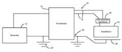
- FIG. 1shows a block diagram of a system, in accordance with an embodiment of the invention, for heating a biological site in a patient's body;
- FIG. 2shows a graph of various comparative waveforms
- FIG. 3shows a schematic representation of one embodiment of a component of the system of FIG. 1 ;
- FIG. 4shows a schematic representation of another embodiment of the component of the system of FIG. 1 ;
- FIG. 5shows a block diagram of a system, in accordance with a second embodiment of the invention, for heating a biological site in a patient's body.
- a systemfor heating a biological site in a patient's body is illustrated and is designated generally by the reference numeral 10 .
- the system 10comprises a generator 12 for generating electromagnetic energy, more particularly, radiofrequency (RF) energy.
- RFradiofrequency
- a transformer 14is connected to an output of the RF generator 12 .
- At least two active electrodes 16are connected to outputs of the transformer 14 , as will be described in greater detail below.
- activeis meant that, unless the context clearly indicates otherwise, the electrode is used to impart energy to the site.
- the system 10makes use of a patient's body as an impedance 18 and a closed circuit is formed by the use of a reference, or indifferent, electrode 20 .
- the reference electrode 20is tied to a ground 22 of the RF generator 12 .
- the transformer 14is a centre-tapped transformer, a secondary winding of the transformer 14 having a centre tap 24 to form two separate sub-windings.
- the reference electrode 20is connected to the centre tap 24 .
- One of the active electrodes 16is connected to an opposed, or free, end of each of the sub-windings of the transformer 14 formed by the centre tapping of the secondary winding.
- the transformer 14may, optionally have intermediate taps (not shown) formed between the centre tap and each free end of each sub-winding. In that case, at least one active electrode may be connected to adjacent intermediate taps. The positions of the intermediate taps are selected to maintain sufficient potential difference between adjacent electrodes at the site to produce longer lesions.
- the transformer 14makes use of a 1:1 ratio between its primary winding and the secondary winding. Different ratios may be employed bearing in mind that, if a number of turns of the windings of the secondary winding are increased relative to that of the primary winding, the voltage across each secondary winding will increase with a corresponding decrease in current.
- the materials used in the transformer 14are selected to be capable of withstanding energy levels and frequencies involved in ablative therapies.
- the transformer 14 and the materials usedare optimised to ensure maximum transfer of energy to the active electrodes 16 .
- suitable materials for the transformer 14include nickel-zinc or manganese-zinc ferrites for a core of the transformer 14 , in particular F 8 , F 12 , F 14 ferrites. These materials are able to operate at the required frequencies and have the necessary high initial permeability and high saturation flux. It will be appreciated that dimensions of the core, number of turns of the windings and the diameter used for the windings are selected so that the transformer 14 has low insertion losses to ensure efficient transfer of energy.
- the primary winding of the transformer 14matches the output impendence of the generator.
- the generator 12 used in trialshad an output impedance of between about 30 and 300 ohms.
- a series resistor and/or a parallel capacitormay be required to effect impedance matching.
- the system 10is designed particularly for use in the production of lesions at a site in a patient's body for treating various disorders such as atrial fibrillation, ventricular tachycardia, tumour ablation, pain management, etc.
- various disorderssuch as atrial fibrillation, ventricular tachycardia, tumour ablation, pain management, etc.
- systems for treatment of these disordershave used a single electrode with a backplate under the patient's body forming a return connection. This results in a large percentage of energy dissipation through the patient's body rather than being used for ablative purposes at the site in the patient's body.
- an inter-electrode impedanceillustrated schematically at 26 , is created between the active electrodes 16 resulting in greater energy transfer between the electrodes 16 rather than through the patient's body.
- waveform 28is the voltage waveform of a single electrode of a prior art system.
- Voltage waveforms 30 and 32are the 180° out of phase waveforms of each active electrode 16 of the system 10 of the present invention and waveform 34 is the sum of the absolute values of the amplitudes of the waveforms 30 and 32 .
- the voltage between the electrodes 16as represented by the waveform 34 , is the same as the voltage of a single electrode 28 but that the energy is concentrated between the active electrodes 16 rather than between an electrode and any indifferent electrode relying on the patient's body.
- the energy of the system 10is no higher than that of a prior art system as the energy applied to each active electrode 16 by the transformer 14 is half that applied to the single electrode of the prior art system.
- the reason for thisis that the inter-electrode impedance 26 is much lower than that of the patient's body resulting in energy transfer between the electrodes 16 rather than dissipation of energy through the patient's body.
- test 24the use of the two out of phase electrodes 16 of the present system 10 (test 24 ) resulted in a significantly deeper lesion than using two electrodes in phase as shown by test 28 .
- one electrodemay be placed thorascopically through the chest with a second electrode being inserted via a catheter inside the heart to achieve lesions through the heart wall.
- the component 30includes an inner electrode 32 which is a retractable electrode inserted via a catheter 34 .
- the inner electrode 32is screwed into position in tissue 36 at the site to be treated by means of a screw driver stylet (not shown) inserted through a lumen of the catheter 34 to extend the screw tipped electrode 32 relative to an outer, second electrode 38 into the tissue 36 of the heart wall.
- the second electrode 38which may be fixed or retractable, is placed in contact with the endocardium of the heart to effect the production of a transmural legion 40 .
- the actual length of exposed metal of the screw electrode 32can be optimised by insulating a portion of the screw.
- the screw tipmay be 20 mm long but only the most distal 5 mm is exposed metal. It will also be appreciated that the actual depth to which the electrode 32 is screwed into the tissue 36 of the heart wall is variable depending on the treatment required.
- the two electrodes 32 , 38are insulated from each other.
- FIG. 4 of the drawingsA variation of this arrangement is the use of two screw-tipped electrodes insulated from each other.
- This embodiment of the componentis shown in FIG. 4 of the drawings. With reference to FIG. 3 of the drawings, like reference numerals refer to like parts unless otherwise specified.
- both electrodes 32 and 38are screw-tipped or helical-tipped.
- the screw tip of the inner electrode 32has a larger pitch than the outer electrode 38 .
- the electrode 32is screwed into the tissue 36 of the heart wall to a greater depth than the electrode 38 .
- the finer pitched, outer electrodeis urged into contact with the endocardium.
- screw depthcan be optimised depending on the depth of the conductive fibres causing the arrhythmia.
- the transformer 14 of the system 10has multiple taps in its secondary winding.
- This embodiment of the inventionis illustrated schematically in FIG. 5 of the drawings. With reference to FIG. 1 of the drawings, like reference numerals refer to like parts, unless otherwise specified.
- the transformer 14has a primary winding 14 . 1 and a secondary winding 14 . 2 wound about a core 14 . 3 .
- the core 14 . 3is made from one of the materials referred to above.
- the secondary winding 14 . 3has the centre tap 24 and an intermediate tap 42 connected between each end tap 44 and the centre tap 24 .
- An active electrode 16is connected to each tap 42 and 44 and the ground electrode 20 is connected to the centre tap 24 .
- the signals provided to each electrode 16 on the same side of the centre tap 24are in phase but are at a predetermined potential difference relative to each other and to the centre tap 24 .
- the value of this potential differenceis governed by the number of turns of the secondary winding.
- the signals provided to the taps 42 and 44 and, hence, the electrodes 16 connected to those taps 42 and 44 , on one side of the centre tap 24are 180° out of phase with the signals provided to the taps 42 and 44 and, hence, their associated electrodes 16 , on the other side of the centre tap.
- the intermediate taps 42With the provision of the intermediate taps 42 , a greater surface area of the site can be heated. Hence, where the site is undergoing heating to create lesions, longer lesions are formed as a result of using the electrodes 16 connected to the intermediate taps 42 in addition to the electrodes 44 connected to the end taps 44 .
- Optimisation of the system 10involves the positioning of the tap 24 on the secondary winding of the transformer 14 as well as the shape and size of the electrodes 16 .
- the electrodes connected to the sub-windings of the secondary windingmay be arranged in groups, for example, pairs. By placing the electrodes in groups, each electrode may impart lower energy to the site thereby reducing the likelihood of charring.
- use of multiple electrodescan be used for pain management with the RF energy being delivered through at least two of the electrodes simultaneously. The positioning of two electrodes may be less dangerous than a single electrode with an earth electrode.
- a system 10 and methodare provided where, due to energy transfer between the active electrodes 16 , deeper lesion production and more accurate lesion production is facilitated.
- the use of a pair of active electrodesreduces the risks involved in the production of lesions for treatment of various disorders.
- the use of at least two active electrodesis of significant benefit in creating linear lesions such as used in “Maze-like” procedures as well as in the production of transmural lesions which are beneficial in treating ventricular tachycardia.
- the centre tapped transformerconsiderably reduces the complexity of the system 10 as the need for complicated and expensive control circuitry is obviated.
- the transformer 14provides the energy sources in a simple but reliable way.
- the use of the transformer 14also obviates the need for complex set-up procedures. In effect, the transformer 14 need only be connected to the generator 12 , the electrodes 16 positioned and the system 10 is ready for use. No complicated calibration or training procedures are required to use the system 10 .
Landscapes
- Engineering & Computer Science (AREA)
- Health & Medical Sciences (AREA)
- Surgery (AREA)
- Life Sciences & Earth Sciences (AREA)
- Medical Informatics (AREA)
- General Health & Medical Sciences (AREA)
- Nuclear Medicine, Radiotherapy & Molecular Imaging (AREA)
- Plasma & Fusion (AREA)
- Biomedical Technology (AREA)
- Heart & Thoracic Surgery (AREA)
- Physics & Mathematics (AREA)
- Molecular Biology (AREA)
- Animal Behavior & Ethology (AREA)
- Otolaryngology (AREA)
- Public Health (AREA)
- Veterinary Medicine (AREA)
- Power Engineering (AREA)
- Surgical Instruments (AREA)
- Electrotherapy Devices (AREA)
- Pharmaceuticals Containing Other Organic And Inorganic Compounds (AREA)
- Thermotherapy And Cooling Therapy Devices (AREA)
Abstract
Description
| TABLE 1 | |||||
| Spa- | |||||
| cing | Power | Time | Depth | ||
| No. | Notes | (mm) | (W) | (s) | (mm) |
| 1 | 2cath 2 mm elect in phase | 0 | 20 | 120 | 4 |
| 2 | 2cath 2 mm elect out phase | 0 | 20 | 120 | 3.5 |
| 3 | 2cath 2 mm elect out phase | 2 | 20 | 120 | 3.5 |
| 4 | 2cath 2 mm elect out phase | 5 | 20 | 120 | 6 |
| 5 | 2cath 2 mm elect out phase | 6.5 | 20 | 120 | 4.5 |
| 6 | 2cath 2 mm elect out phase | 9 | 20 | 120 | 5 |
| 7 | 2cath 2 mm elect in phase | 0 | 20 | 120 | No |
| (crossed) | lesion | ||||
| 8 | 2cath 2 mm elect in phase | 0 | 20 | 120 | No |
| (crossed) | lesion | ||||
| 9 | 2cath 2 mm elect in phase | 0 | 20 | 120 | 4 |
| 10 | 1cath 2 mm | — | 20 | 120 | 4.5 |
| 11 | Three burn series | — | 20 | 120 | 5 |
| (as 10) #1 | |||||
| 12 | Three burn series | — | 20 | 120 | 5 |
| (as 10) #2 | |||||
| 13 | Three burn series | — | 20 | 120 | 5 |
| (as 10) #3 | |||||
| 14 | 2cath 2 mm elect in phase | 7 | 20 | 120 | 3.5 |
| 15 | 2cath pairs elect out | 4 | 20 | 120 | 6 |
| phase (long elect) | |||||
| 16 | 2cath 4 mm elect in phase | 0 | 20 | 120 | 0.5 |
| 17 | 2cath 4 mm elect out phase | 0 | 20 | 120 | 6 |
| 18 | 2cath 4 mm elect out phase | 4 | 20 | 120 | 6 |
| 19 | 2cath 4 mm elect out phase | 7 | 20 | 120 | 8 |
| 20 | 2cath 4 mm elect out phase | 11 | 20 | 120 | 8 |
| 21 | 2cath 4 mm elect in phase | 0 | 20 | 120 | 0.5 |
| 22 | 2cath 4 mm elect in phase | 6 | 20 | 120 | 0.5 |
| 23 | 1 cath 4 mm | — | 20 | 120 | 5 |
| 24 | 2cath 4 mm elect out phase | — | 20 | 120 | 13 - |
| transmural | high | ||||
| damage | |||||
| 25 | 2cath 4 mm elect out phase | 4 | 10 | 120 | 5 |
| 26 | 2cath 4 mm elect out phase | 4 | 20 | 60 | 7 |
| 27 | 2cath 4 mm elect out phase | 4 | 20 | 30 | 5 |
| 28 | 2cath 4 mm elect in phase | — | 20 | 120 | 6 - |
| transmural | low | ||||
| damage | |||||
Claims (22)
Applications Claiming Priority (3)
| Application Number | Priority Date | Filing Date | Title |
|---|---|---|---|
| AU2002952318AAU2002952318A0 (en) | 2002-10-29 | 2002-10-29 | Production of lesions in a body |
| AU2002952318 | 2002-10-29 | ||
| PCT/AU2003/001421WO2004039274A1 (en) | 2002-10-29 | 2003-10-28 | System for, and method of, heating a biological site in a patient's body |
Publications (2)
| Publication Number | Publication Date |
|---|---|
| US20050273091A1 US20050273091A1 (en) | 2005-12-08 |
| US7871410B2true US7871410B2 (en) | 2011-01-18 |
Family
ID=28795711
Family Applications (1)
| Application Number | Title | Priority Date | Filing Date |
|---|---|---|---|
| US10/532,391Expired - Fee RelatedUS7871410B2 (en) | 2002-10-29 | 2003-10-28 | System for, and method of, heating a biological site in a patient's body |
Country Status (10)
| Country | Link |
|---|---|
| US (1) | US7871410B2 (en) |
| EP (1) | EP1562508B1 (en) |
| JP (1) | JP4445393B2 (en) |
| CN (1) | CN1725983B (en) |
| AT (1) | ATE505148T1 (en) |
| AU (1) | AU2002952318A0 (en) |
| CA (1) | CA2503765A1 (en) |
| DE (1) | DE60336748D1 (en) |
| NZ (1) | NZ539317A (en) |
| WO (1) | WO2004039274A1 (en) |
Cited By (2)
| Publication number | Priority date | Publication date | Assignee | Title |
|---|---|---|---|---|
| US20080300587A1 (en)* | 2005-03-02 | 2008-12-04 | Cathrx Ltd | Heat Treatment Catheter |
| US10849684B2 (en) | 2013-06-07 | 2020-12-01 | Cathrx Ltd | Electrical lead for a catheter and method of manufacturing |
Families Citing this family (27)
| Publication number | Priority date | Publication date | Assignee | Title |
|---|---|---|---|---|
| US7186234B2 (en) | 1995-11-22 | 2007-03-06 | Arthrocare Corporation | Electrosurgical apparatus and methods for treatment and removal of tissue |
| AU2002952318A0 (en) | 2002-10-29 | 2002-11-14 | Advanced Metal Coatings Pty Limited | Production of lesions in a body |
| US7717618B2 (en)* | 2005-12-30 | 2010-05-18 | Optech Ventures, Llc | Apparatus and method for high resolution temperature measurement and for hyperthermia therapy |
| US7691101B2 (en)* | 2006-01-06 | 2010-04-06 | Arthrocare Corporation | Electrosurgical method and system for treating foot ulcer |
| US8876746B2 (en) | 2006-01-06 | 2014-11-04 | Arthrocare Corporation | Electrosurgical system and method for treating chronic wound tissue |
| WO2007143445A2 (en) | 2006-05-30 | 2007-12-13 | Arthrocare Corporation | Hard tissue ablation system |
| JP4611247B2 (en)* | 2006-06-14 | 2011-01-12 | オリンパスメディカルシステムズ株式会社 | High frequency treatment tool |
| AU2007231704B2 (en)* | 2006-11-29 | 2011-02-24 | Cathrx Ltd | Heat treating a biological site in a patient's body |
| GB2452103B (en) | 2007-01-05 | 2011-08-31 | Arthrocare Corp | Electrosurgical system with suction control apparatus and system |
| US7862560B2 (en)* | 2007-03-23 | 2011-01-04 | Arthrocare Corporation | Ablation apparatus having reduced nerve stimulation and related methods |
| US9358063B2 (en) | 2008-02-14 | 2016-06-07 | Arthrocare Corporation | Ablation performance indicator for electrosurgical devices |
| KR20110008003A (en)* | 2008-02-20 | 2011-01-25 | 시네론 메디컬 리미티드 | Personal skin treatment device and how to use it |
| US9782217B2 (en) | 2008-11-13 | 2017-10-10 | Covidien Ag | Radio frequency generator and method for a cordless medical cauterization and cutting device |
| US8574187B2 (en) | 2009-03-09 | 2013-11-05 | Arthrocare Corporation | System and method of an electrosurgical controller with output RF energy control |
| US8257350B2 (en) | 2009-06-17 | 2012-09-04 | Arthrocare Corporation | Method and system of an electrosurgical controller with wave-shaping |
| US8372067B2 (en) | 2009-12-09 | 2013-02-12 | Arthrocare Corporation | Electrosurgery irrigation primer systems and methods |
| US8747399B2 (en) | 2010-04-06 | 2014-06-10 | Arthrocare Corporation | Method and system of reduction of low frequency muscle stimulation during electrosurgical procedures |
| US8568405B2 (en) | 2010-10-15 | 2013-10-29 | Arthrocare Corporation | Electrosurgical wand and related method and system |
| US8685018B2 (en) | 2010-10-15 | 2014-04-01 | Arthrocare Corporation | Electrosurgical wand and related method and system |
| USD658760S1 (en) | 2010-10-15 | 2012-05-01 | Arthrocare Corporation | Wound care electrosurgical wand |
| US9943360B2 (en) | 2011-01-30 | 2018-04-17 | University Health Network | Coil electrode for thermal therapy |
| US9131597B2 (en) | 2011-02-02 | 2015-09-08 | Arthrocare Corporation | Electrosurgical system and method for treating hard body tissue |
| KR101415902B1 (en)* | 2012-05-18 | 2014-07-08 | 신경민 | Catheter provided with cauterization system |
| US9693818B2 (en) | 2013-03-07 | 2017-07-04 | Arthrocare Corporation | Methods and systems related to electrosurgical wands |
| US9713489B2 (en) | 2013-03-07 | 2017-07-25 | Arthrocare Corporation | Electrosurgical methods and systems |
| US9801678B2 (en) | 2013-03-13 | 2017-10-31 | Arthrocare Corporation | Method and system of controlling conductive fluid flow during an electrosurgical procedure |
| CN104287827B (en)* | 2013-07-19 | 2018-03-02 | 卡尔迪雅(天津)医疗器械有限公司 | One kind removes renal sympathetic nerve radio-frequency ablation electrode and radio frequency ablation system |
Citations (38)
| Publication number | Priority date | Publication date | Assignee | Title |
|---|---|---|---|---|
| US3601126A (en)* | 1969-01-08 | 1971-08-24 | Electro Medical Systems Inc | High frequency electrosurgical apparatus |
| US3730188A (en) | 1971-03-24 | 1973-05-01 | I Ellman | Electrosurgical apparatus for dental use |
| US3913583A (en)* | 1974-06-03 | 1975-10-21 | Sybron Corp | Control circuit for electrosurgical units |
| US4101984A (en) | 1975-05-09 | 1978-07-25 | Macgregor David C | Cardiovascular prosthetic devices and implants with porous systems |
| US4200105A (en)* | 1978-05-26 | 1980-04-29 | Dentsply Research & Development Corp. | Electrosurgical safety circuit |
| US4520818A (en)* | 1983-02-28 | 1985-06-04 | Codman & Shurtleff, Inc. | High dielectric output circuit for electrosurgical power source |
| US4531524A (en)* | 1982-12-27 | 1985-07-30 | Rdm International, Inc. | Circuit apparatus and method for electrothermal treatment of cancer eye |
| US4871421A (en)* | 1988-09-15 | 1989-10-03 | Lam Research Corporation | Split-phase driver for plasma etch system |
| WO1990008466A1 (en) | 1989-01-31 | 1990-08-09 | W.L. Gore & Associates, Inc. | Patch electrodes for use with defibrillators |
| EP0479435A2 (en) | 1990-10-01 | 1992-04-08 | Ventritex, Inc. | Multiple electrode deployable lead |
| US5269810A (en) | 1992-06-19 | 1993-12-14 | W. L. Gore & Associates, Inc. | Patch electrode |
| US5300068A (en)* | 1992-04-21 | 1994-04-05 | St. Jude Medical, Inc. | Electrosurgical apparatus |
| US5383917A (en) | 1991-07-05 | 1995-01-24 | Jawahar M. Desai | Device and method for multi-phase radio-frequency ablation |
| US5431649A (en)* | 1993-08-27 | 1995-07-11 | Medtronic, Inc. | Method and apparatus for R-F ablation |
| WO1995025472A1 (en) | 1994-03-23 | 1995-09-28 | Vidamed, Inc. | Dual-channel rf power delivery system |
| JPH08635A (en) | 1994-06-22 | 1996-01-09 | Tokai Rika Co Ltd | Medical coagulating device |
| US5507743A (en)* | 1993-11-08 | 1996-04-16 | Zomed International | Coiled RF electrode treatment apparatus |
| US5522874A (en) | 1994-07-28 | 1996-06-04 | Gates; James T. | Medical lead having segmented electrode |
| US5540684A (en)* | 1994-07-28 | 1996-07-30 | Hassler, Jr.; William L. | Method and apparatus for electrosurgically treating tissue |
| WO1996036860A2 (en) | 1995-05-01 | 1996-11-21 | Ep Technologies, Inc. | Systems and methods for sensing sub-surface temperatures in body tissue during ablation with actively cooled electrodes |
| WO1996037156A1 (en) | 1995-05-22 | 1996-11-28 | Issa Muta M | Resectoscope electrode assembly with simultaneous cutting and coagulation |
| US5615091A (en)* | 1995-10-11 | 1997-03-25 | Biochem International, Inc. | Isolation transformer for medical equipment |
| US5620481A (en) | 1991-07-05 | 1997-04-15 | Desai; Jawahar M. | Device for multi-phase radio-frequency ablation |
| US5697928A (en) | 1996-09-23 | 1997-12-16 | Uab Research Foundation | Cardic electrode catheter |
| US5834051A (en) | 1995-11-07 | 1998-11-10 | Medtronic, Inc. | Intramuscular stimulation lead with enhanced infection resistance |
| US5892667A (en) | 1994-06-17 | 1999-04-06 | Equi-Tech Licensing Corp. | Symmetrical power system |
| US5931862A (en) | 1997-12-22 | 1999-08-03 | Pacesetter, Inc. | Medical lead and method of making and using with sodium sulfosuccinic ester |
| WO1999058070A2 (en) | 1998-05-08 | 1999-11-18 | Novacept | A radio-frequency generator for an ablation device |
| US6071278A (en) | 1996-02-28 | 2000-06-06 | Ep Technologies, Inc. | Tissue heating and ablation systems and methods using porous electrode structures with specified electrical resistivities |
| US6112123A (en)* | 1998-07-28 | 2000-08-29 | Endonetics, Inc. | Device and method for ablation of tissue |
| US6267757B1 (en)* | 1995-08-09 | 2001-07-31 | Eclipse Surgical Technologies, Inc. | Revascularization with RF ablation |
| US20010014804A1 (en)* | 2000-02-08 | 2001-08-16 | Goble Colin C.O. | Electrosurgical instrument and an electrosurgery system including such an instrument |
| US6280441B1 (en)* | 1997-12-15 | 2001-08-28 | Sherwood Services Ag | Apparatus and method for RF lesioning |
| WO2002080792A1 (en) | 2001-04-04 | 2002-10-17 | Moshe Ein-Gal | Electrosurgical apparatus |
| US6485487B1 (en)* | 1998-05-05 | 2002-11-26 | Cardiac Pacemakers, Inc. | RF ablation apparatus having high output impedance drivers |
| US20030199868A1 (en) | 1991-07-05 | 2003-10-23 | Desai Jawahar M. | Device and method for multi-phase radio-frequency ablation |
| WO2004039274A1 (en) | 2002-10-29 | 2004-05-13 | Cathrx Pty Ltd | System for, and method of, heating a biological site in a patient's body |
| US7178234B2 (en) | 1999-10-26 | 2007-02-20 | Ibiden Co., Ltd. | Method of manufacturing multi-layer printed circuit board |
- 2002
- 2002-10-29AUAU2002952318Apatent/AU2002952318A0/ennot_activeAbandoned
- 2003
- 2003-10-28EPEP03769029Apatent/EP1562508B1/ennot_activeExpired - Lifetime
- 2003-10-28NZNZ539317Apatent/NZ539317A/enunknown
- 2003-10-28DEDE60336748Tpatent/DE60336748D1/ennot_activeExpired - Lifetime
- 2003-10-28WOPCT/AU2003/001421patent/WO2004039274A1/enactiveApplication Filing
- 2003-10-28CACA002503765Apatent/CA2503765A1/ennot_activeAbandoned
- 2003-10-28JPJP2004547274Apatent/JP4445393B2/ennot_activeExpired - Fee Related
- 2003-10-28USUS10/532,391patent/US7871410B2/ennot_activeExpired - Fee Related
- 2003-10-28CNCN2003801021965Apatent/CN1725983B/ennot_activeExpired - Fee Related
- 2003-10-28ATAT03769029Tpatent/ATE505148T1/ennot_activeIP Right Cessation
Patent Citations (41)
| Publication number | Priority date | Publication date | Assignee | Title |
|---|---|---|---|---|
| US3601126A (en)* | 1969-01-08 | 1971-08-24 | Electro Medical Systems Inc | High frequency electrosurgical apparatus |
| US3730188A (en) | 1971-03-24 | 1973-05-01 | I Ellman | Electrosurgical apparatus for dental use |
| US3913583A (en)* | 1974-06-03 | 1975-10-21 | Sybron Corp | Control circuit for electrosurgical units |
| US4101984A (en) | 1975-05-09 | 1978-07-25 | Macgregor David C | Cardiovascular prosthetic devices and implants with porous systems |
| US4200105A (en)* | 1978-05-26 | 1980-04-29 | Dentsply Research & Development Corp. | Electrosurgical safety circuit |
| US4531524A (en)* | 1982-12-27 | 1985-07-30 | Rdm International, Inc. | Circuit apparatus and method for electrothermal treatment of cancer eye |
| US4520818A (en)* | 1983-02-28 | 1985-06-04 | Codman & Shurtleff, Inc. | High dielectric output circuit for electrosurgical power source |
| US4871421A (en)* | 1988-09-15 | 1989-10-03 | Lam Research Corporation | Split-phase driver for plasma etch system |
| WO1990008466A1 (en) | 1989-01-31 | 1990-08-09 | W.L. Gore & Associates, Inc. | Patch electrodes for use with defibrillators |
| EP0479435A2 (en) | 1990-10-01 | 1992-04-08 | Ventritex, Inc. | Multiple electrode deployable lead |
| EP0479435A3 (en) | 1990-10-01 | 1992-06-24 | Ventritex, Inc. | Multiple electrode deployable lead |
| US5620481A (en) | 1991-07-05 | 1997-04-15 | Desai; Jawahar M. | Device for multi-phase radio-frequency ablation |
| US5693078A (en) | 1991-07-05 | 1997-12-02 | Jawahar M. Desai | Device and method for multi-phase radio-frequency ablation |
| US5383917A (en) | 1991-07-05 | 1995-01-24 | Jawahar M. Desai | Device and method for multi-phase radio-frequency ablation |
| US20030199868A1 (en) | 1991-07-05 | 2003-10-23 | Desai Jawahar M. | Device and method for multi-phase radio-frequency ablation |
| US5300068A (en)* | 1992-04-21 | 1994-04-05 | St. Jude Medical, Inc. | Electrosurgical apparatus |
| US5269810A (en) | 1992-06-19 | 1993-12-14 | W. L. Gore & Associates, Inc. | Patch electrode |
| US5431649A (en)* | 1993-08-27 | 1995-07-11 | Medtronic, Inc. | Method and apparatus for R-F ablation |
| US5507743A (en)* | 1993-11-08 | 1996-04-16 | Zomed International | Coiled RF electrode treatment apparatus |
| WO1995025472A1 (en) | 1994-03-23 | 1995-09-28 | Vidamed, Inc. | Dual-channel rf power delivery system |
| US5892667A (en) | 1994-06-17 | 1999-04-06 | Equi-Tech Licensing Corp. | Symmetrical power system |
| JPH08635A (en) | 1994-06-22 | 1996-01-09 | Tokai Rika Co Ltd | Medical coagulating device |
| US5522874A (en) | 1994-07-28 | 1996-06-04 | Gates; James T. | Medical lead having segmented electrode |
| US5540684A (en)* | 1994-07-28 | 1996-07-30 | Hassler, Jr.; William L. | Method and apparatus for electrosurgically treating tissue |
| WO1996036860A2 (en) | 1995-05-01 | 1996-11-21 | Ep Technologies, Inc. | Systems and methods for sensing sub-surface temperatures in body tissue during ablation with actively cooled electrodes |
| WO1996037156A1 (en) | 1995-05-22 | 1996-11-28 | Issa Muta M | Resectoscope electrode assembly with simultaneous cutting and coagulation |
| US6267757B1 (en)* | 1995-08-09 | 2001-07-31 | Eclipse Surgical Technologies, Inc. | Revascularization with RF ablation |
| US5615091A (en)* | 1995-10-11 | 1997-03-25 | Biochem International, Inc. | Isolation transformer for medical equipment |
| US5834051A (en) | 1995-11-07 | 1998-11-10 | Medtronic, Inc. | Intramuscular stimulation lead with enhanced infection resistance |
| US6071278A (en) | 1996-02-28 | 2000-06-06 | Ep Technologies, Inc. | Tissue heating and ablation systems and methods using porous electrode structures with specified electrical resistivities |
| US5697928A (en) | 1996-09-23 | 1997-12-16 | Uab Research Foundation | Cardic electrode catheter |
| US6280441B1 (en)* | 1997-12-15 | 2001-08-28 | Sherwood Services Ag | Apparatus and method for RF lesioning |
| US5931862A (en) | 1997-12-22 | 1999-08-03 | Pacesetter, Inc. | Medical lead and method of making and using with sodium sulfosuccinic ester |
| US6485487B1 (en)* | 1998-05-05 | 2002-11-26 | Cardiac Pacemakers, Inc. | RF ablation apparatus having high output impedance drivers |
| US6508815B1 (en)* | 1998-05-08 | 2003-01-21 | Novacept | Radio-frequency generator for powering an ablation device |
| WO1999058070A2 (en) | 1998-05-08 | 1999-11-18 | Novacept | A radio-frequency generator for an ablation device |
| US6112123A (en)* | 1998-07-28 | 2000-08-29 | Endonetics, Inc. | Device and method for ablation of tissue |
| US7178234B2 (en) | 1999-10-26 | 2007-02-20 | Ibiden Co., Ltd. | Method of manufacturing multi-layer printed circuit board |
| US20010014804A1 (en)* | 2000-02-08 | 2001-08-16 | Goble Colin C.O. | Electrosurgical instrument and an electrosurgery system including such an instrument |
| WO2002080792A1 (en) | 2001-04-04 | 2002-10-17 | Moshe Ein-Gal | Electrosurgical apparatus |
| WO2004039274A1 (en) | 2002-10-29 | 2004-05-13 | Cathrx Pty Ltd | System for, and method of, heating a biological site in a patient's body |
Non-Patent Citations (3)
| Title |
|---|
| International Search Report mailed on Feb. 2, 2004 for PCT patent application No. PCT/AU2003/001421 filed on Oct. 28, 2003, 7 pages. |
| Supplementary Partial European Search Report mailed Feb. 12, 2007 for EP Application No. 01977995.8, five pages. |
| Supplementary Partial European Search Report mailed Feb. 20, 2006, for EP Patent Application No. 03769029.4, filed Oct. 28, 2003, 7 pages. |
Cited By (2)
| Publication number | Priority date | Publication date | Assignee | Title |
|---|---|---|---|---|
| US20080300587A1 (en)* | 2005-03-02 | 2008-12-04 | Cathrx Ltd | Heat Treatment Catheter |
| US10849684B2 (en) | 2013-06-07 | 2020-12-01 | Cathrx Ltd | Electrical lead for a catheter and method of manufacturing |
Also Published As
| Publication number | Publication date |
|---|---|
| US20050273091A1 (en) | 2005-12-08 |
| EP1562508B1 (en) | 2011-04-13 |
| JP2006504453A (en) | 2006-02-09 |
| EP1562508A4 (en) | 2006-04-05 |
| WO2004039274A1 (en) | 2004-05-13 |
| ATE505148T1 (en) | 2011-04-15 |
| EP1562508A1 (en) | 2005-08-17 |
| AU2002952318A0 (en) | 2002-11-14 |
| CN1725983B (en) | 2010-04-21 |
| JP4445393B2 (en) | 2010-04-07 |
| NZ539317A (en) | 2007-06-29 |
| CA2503765A1 (en) | 2004-05-13 |
| CN1725983A (en) | 2006-01-25 |
| DE60336748D1 (en) | 2011-05-26 |
Similar Documents
| Publication | Publication Date | Title |
|---|---|---|
| US7871410B2 (en) | System for, and method of, heating a biological site in a patient's body | |
| US12245802B2 (en) | Generating irreversible electroporation and radiofrequency-abaltion (IRE/RFA) waveforms | |
| AU2007231704B2 (en) | Heat treating a biological site in a patient's body | |
| US6958064B2 (en) | Systems and methods for performing simultaneous ablation | |
| US7115124B1 (en) | Device and method for tissue ablation using bipolar radio-frequency current | |
| US20110208179A1 (en) | Patient Isolation in a Microwave-Radio Frequency Generator | |
| US20080300587A1 (en) | Heat Treatment Catheter | |
| EP1511534A2 (en) | Device for electrosurgically destroying body tissue | |
| CN110327112B (en) | Radiofrequency ablation forceps and multi-electrode radiofrequency ablation system comprising radiofrequency ablation forceps | |
| US20010047168A1 (en) | Echogenic wire knife | |
| CN204814162U (en) | Acupunture needle type radio frequency electricity needle | |
| AU2003277943B2 (en) | System for, and method of, heating a biological site in a patient's body | |
| WO2022139797A1 (en) | Electronic apparatus for delivering coherent sine burst irreversible electroporation energy to a biological tissue | |
| Mahesha et al. | Monopolar electrosurgery in full-endoscopic spine surgery: the author’s experience | |
| Sanghai et al. | Radiofrequency ablation—to insure or not to insure is the question. | |
| US20240423687A1 (en) | Methods and ablation systems for treatment of sacroiliac joint pain using short, high voltage pulses |
Legal Events
| Date | Code | Title | Description |
|---|---|---|---|
| AS | Assignment | Owner name:CATHRX PTY LTD, AUSTRALIA Free format text:ASSIGNMENT OF ASSIGNORS INTEREST;ASSIGNORS:BOOTH, NORMAN;CHONG, EVAN K.;REEL/FRAME:016984/0185 Effective date:20050421 | |
| AS | Assignment | Owner name:CATHRX LTD, AUSTRALIA Free format text:CHANGE OF NAME;ASSIGNOR:CATHRX PTY LTD;REEL/FRAME:017044/0528 Effective date:20050805 | |
| STCF | Information on status: patent grant | Free format text:PATENTED CASE | |
| FPAY | Fee payment | Year of fee payment:4 | |
| FEPP | Fee payment procedure | Free format text:PAYOR NUMBER ASSIGNED (ORIGINAL EVENT CODE: ASPN); ENTITY STATUS OF PATENT OWNER: SMALL ENTITY | |
| CC | Certificate of correction | ||
| MAFP | Maintenance fee payment | Free format text:PAYMENT OF MAINTENANCE FEE, 8TH YR, SMALL ENTITY (ORIGINAL EVENT CODE: M2552) Year of fee payment:8 | |
| FEPP | Fee payment procedure | Free format text:MAINTENANCE FEE REMINDER MAILED (ORIGINAL EVENT CODE: REM.); ENTITY STATUS OF PATENT OWNER: SMALL ENTITY | |
| LAPS | Lapse for failure to pay maintenance fees | Free format text:PATENT EXPIRED FOR FAILURE TO PAY MAINTENANCE FEES (ORIGINAL EVENT CODE: EXP.); ENTITY STATUS OF PATENT OWNER: SMALL ENTITY | |
| STCH | Information on status: patent discontinuation | Free format text:PATENT EXPIRED DUE TO NONPAYMENT OF MAINTENANCE FEES UNDER 37 CFR 1.362 | |
| FP | Lapsed due to failure to pay maintenance fee | Effective date:20230118 |