US7871080B2 - Tool-less blade clamping apparatus for a reciprocating tool - Google Patents
Tool-less blade clamping apparatus for a reciprocating toolDownload PDFInfo
- Publication number
- US7871080B2 US7871080B2US10/760,110US76011004AUS7871080B2US 7871080 B2US7871080 B2US 7871080B2US 76011004 AUS76011004 AUS 76011004AUS 7871080 B2US7871080 B2US 7871080B2
- Authority
- US
- United States
- Prior art keywords
- blade
- slot
- plunger
- clamping apparatus
- inner sleeve
- Prior art date
- Legal status (The legal status is an assumption and is not a legal conclusion. Google has not performed a legal analysis and makes no representation as to the accuracy of the status listed.)
- Expired - Fee Related, expires
Links
Images


Classifications
- B—PERFORMING OPERATIONS; TRANSPORTING
- B23—MACHINE TOOLS; METAL-WORKING NOT OTHERWISE PROVIDED FOR
- B23D—PLANING; SLOTTING; SHEARING; BROACHING; SAWING; FILING; SCRAPING; LIKE OPERATIONS FOR WORKING METAL BY REMOVING MATERIAL, NOT OTHERWISE PROVIDED FOR
- B23D51/00—Sawing machines or sawing devices working with straight blades, characterised only by constructional features of particular parts; Carrying or attaching means for tools, covered by this subclass, which are connected to a carrier at both ends
- B23D51/08—Sawing machines or sawing devices working with straight blades, characterised only by constructional features of particular parts; Carrying or attaching means for tools, covered by this subclass, which are connected to a carrier at both ends of devices for mounting straight saw blades or other tools
- B23D51/10—Sawing machines or sawing devices working with straight blades, characterised only by constructional features of particular parts; Carrying or attaching means for tools, covered by this subclass, which are connected to a carrier at both ends of devices for mounting straight saw blades or other tools for hand-held or hand-operated devices
- Y—GENERAL TAGGING OF NEW TECHNOLOGICAL DEVELOPMENTS; GENERAL TAGGING OF CROSS-SECTIONAL TECHNOLOGIES SPANNING OVER SEVERAL SECTIONS OF THE IPC; TECHNICAL SUBJECTS COVERED BY FORMER USPC CROSS-REFERENCE ART COLLECTIONS [XRACs] AND DIGESTS
- Y10—TECHNICAL SUBJECTS COVERED BY FORMER USPC
- Y10T—TECHNICAL SUBJECTS COVERED BY FORMER US CLASSIFICATION
- Y10T279/00—Chucks or sockets
- Y10T279/17—Socket type
- Y10T279/17666—Radially reciprocating jaws
- Y10T279/17692—Moving-cam actuator
- Y10T279/17717—Rotary eccentric-cam sleeve
- Y—GENERAL TAGGING OF NEW TECHNOLOGICAL DEVELOPMENTS; GENERAL TAGGING OF CROSS-SECTIONAL TECHNOLOGIES SPANNING OVER SEVERAL SECTIONS OF THE IPC; TECHNICAL SUBJECTS COVERED BY FORMER USPC CROSS-REFERENCE ART COLLECTIONS [XRACs] AND DIGESTS
- Y10—TECHNICAL SUBJECTS COVERED BY FORMER USPC
- Y10T—TECHNICAL SUBJECTS COVERED BY FORMER US CLASSIFICATION
- Y10T279/00—Chucks or sockets
- Y10T279/17—Socket type
- Y10T279/17666—Radially reciprocating jaws
- Y10T279/17692—Moving-cam actuator
- Y10T279/17743—Reciprocating cam sleeve
- Y—GENERAL TAGGING OF NEW TECHNOLOGICAL DEVELOPMENTS; GENERAL TAGGING OF CROSS-SECTIONAL TECHNOLOGIES SPANNING OVER SEVERAL SECTIONS OF THE IPC; TECHNICAL SUBJECTS COVERED BY FORMER USPC CROSS-REFERENCE ART COLLECTIONS [XRACs] AND DIGESTS
- Y10—TECHNICAL SUBJECTS COVERED BY FORMER USPC
- Y10T—TECHNICAL SUBJECTS COVERED BY FORMER US CLASSIFICATION
- Y10T279/00—Chucks or sockets
- Y10T279/17—Socket type
- Y10T279/17761—Side detent
- Y10T279/17803—Rotary cam sleeve
- Y—GENERAL TAGGING OF NEW TECHNOLOGICAL DEVELOPMENTS; GENERAL TAGGING OF CROSS-SECTIONAL TECHNOLOGIES SPANNING OVER SEVERAL SECTIONS OF THE IPC; TECHNICAL SUBJECTS COVERED BY FORMER USPC CROSS-REFERENCE ART COLLECTIONS [XRACs] AND DIGESTS
- Y10—TECHNICAL SUBJECTS COVERED BY FORMER USPC
- Y10T—TECHNICAL SUBJECTS COVERED BY FORMER US CLASSIFICATION
- Y10T279/00—Chucks or sockets
- Y10T279/17—Socket type
- Y10T279/17761—Side detent
- Y10T279/17811—Reciprocating sleeve
- Y—GENERAL TAGGING OF NEW TECHNOLOGICAL DEVELOPMENTS; GENERAL TAGGING OF CROSS-SECTIONAL TECHNOLOGIES SPANNING OVER SEVERAL SECTIONS OF THE IPC; TECHNICAL SUBJECTS COVERED BY FORMER USPC CROSS-REFERENCE ART COLLECTIONS [XRACs] AND DIGESTS
- Y10—TECHNICAL SUBJECTS COVERED BY FORMER USPC
- Y10T—TECHNICAL SUBJECTS COVERED BY FORMER US CLASSIFICATION
- Y10T279/00—Chucks or sockets
- Y10T279/32—Means to prevent jaw loosening
- Y—GENERAL TAGGING OF NEW TECHNOLOGICAL DEVELOPMENTS; GENERAL TAGGING OF CROSS-SECTIONAL TECHNOLOGIES SPANNING OVER SEVERAL SECTIONS OF THE IPC; TECHNICAL SUBJECTS COVERED BY FORMER USPC CROSS-REFERENCE ART COLLECTIONS [XRACs] AND DIGESTS
- Y10—TECHNICAL SUBJECTS COVERED BY FORMER USPC
- Y10T—TECHNICAL SUBJECTS COVERED BY FORMER US CLASSIFICATION
- Y10T83/00—Cutting
- Y10T83/929—Tool or tool with support
- Y10T83/9457—Joint or connection
- Y10T83/9473—For rectilinearly reciprocating tool
- Y10T83/9481—Tool is single element reciprocable along elongate cutting edge [e.g., saw blade, etc.]
Definitions
- the present inventiongenerally relates to tools. More particularly, it relates to mechanisms for clamping tool attachments to such tools.
- a tool-less blade clamping apparatusfor a reciprocating tool of the type which has a reciprocating plunger which has a tool attachment receiving slot for receiving a tool attachment of the type that has a shank portion with at least one, and preferably two shoulders spaced from the end of the shank and an aperture in the shank for facilitating holding by the clamping apparatus.
- the clamping apparatushas an unclamped position and a clamped position where the shank portion of the tool attachment can be inserted into the slot as well as an opening in the apparatus itself.
- a tool attachmentIn the unclamped position, a tool attachment can be easily inserted and the shoulders will release the apparatus to move to the clamped position, where the tool attachment is securely retained.
- the apparatusWhen returned to the unclamped position, the apparatus engages the shoulders and pushes the blade from the apparatus.
- the preferred embodimentshave at least one spring biasing the apparatus toward the clamped position, a releasable retaining mechanism for holding said apparatus in its unclamped position after being placed in that position, such that when the retaining mechanism is released responsive to the blade shank portion being inserted into the opening and slot and the shoulders engage the apparatus and is thereafter moved a predetermined distance, the retaining mechanism is released to move to its clamped position.
- the clamping apparatusneeds only to be moved to its unclamped position by manually rotating the outer sleeve or collar, and the apparatus pushes against the shoulders of the blade which causes the blade to normally be ejected from the mechanism as it reaches its unclamped position.
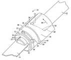
- FIG. 1is a perspective view of the first preferred embodiment of the clamping apparatus shown with a blade inserted in the apparatus in its clamped position;
- FIG. 2is an exploded perspective illustrating the components of the apparatus shown in FIG. 1 ;
- FIG. 3is an enlarged perspective view illustrating a portion of the apparatus shown in FIG. 1 ;
- FIG. 4is a cross-section taken generally along a line perpendicular to the orientation of the slot of the plunger rod at a location through the center of the detente;
- FIG. 5is a perspective view with portions removed to illustrate many of the components of the apparatus shown in FIG. 1 ;
- FIG. 6is a perspective view of the inner sleeve of the apparatus shown in FIG. 1 ;
- FIG. 7is another perspective view of the inner sleeve shown in the apparatus of FIG. 1 ;
- FIG. 8is a perspective view of the outer sleeve of the apparatus shown in FIG. 1 ;
- FIG. 9is another perspective view showing the interior of the outer sleeve of the apparatus shown in FIG. 1 ;
- FIG. 10is a perspective view of the detente used in the apparatus shown in FIG. 1 ;
- FIG. 11is a perspective view of a second preferred embodiment of a clamping apparatus
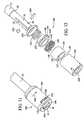
- FIG. 12is an exploded perspective illustrating the components of the apparatus shown in FIG. 11 ;
- FIG. 13is a perspective view of the apparatus shown in FIG. 11 shown in cross-section taken generally through the center of the apparatus along a plane parallel to the slot of the plunger rod;
- FIG. 14is a perspective view of the apparatus shown in FIG. 11 with portions removed to illustrate the relationship of components thereof;
- FIG. 15is a perspective view with portions removed to reveal a cross-section taken generally along a plane transverse to the axis of the apparatus and through the center of the detente;
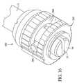
- FIG. 16is a perspective view of a third preferred embodiment of the clamping mechanism.
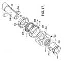
- FIG. 17is an exploded perspective view of the apparatus shown in FIG. 16 ;
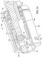
- FIG. 18is a perspective view of the apparatus shown in FIG. 1 with portions removed to illustrate the relationship of components of the apparatus shown in FIG. 16 ;
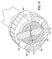
- FIG. 19is a cross-section with portions removed to illustrate a cross-section taken along a plane generally transverse to the axis of the apparatus and taken at a position to reveal the middle of the detente;
- FIG. 20is a perspective view of the clamping collar of the apparatus shown in FIG. 16 ;
- FIG. 21is a perspective view of the control sleeve of the apparatus shown in FIG. 16 ;
- FIG. 22is a perspective is another perspective view of the clamping collar of the apparatus shown in FIG. 16 .
- the clamping apparatusis certainly susceptible for use in applications other than these. It is contemplated that the clamping apparatus may be used in the medical field, particular with surgical instruments that are used with reciprocal saw and cutting blades. Also, while the embodiments of the present invention are particularly suited for use with power hand tools, they could be used with a nonpower hand tool as well as larger stationary power tools that employ tool attachments in a reciprocating manner and where such tool attachments are replaced. The detailed description of the preferred embodiments are described with regard to saber saws which use commercially available saw blades. The present invention should not be limited to the described applications.
- the embodiments of the clamping apparatus of the present inventionare particularly suited for use with a saber saw which has a generally cylindrical plunger rod although plunger rods or structure may be utilized which are other than the circular cross-section. However, if it is other than a circular cross-section throughout a significant part of its length, the plunger rod necessarily requires a generally cylindrical distal end portion in which the embodiments of the present invention are installed.
- the blade described herein in which the clamping mechanism of the embodiments of the present invention are to be usedis of conventional design for saber saw blades, but it should be understood that the various embodiments could be modified to operate with other styles of blades if desired.
- the modificationshould be such that a hole be located somewhere on the shank portion of the blade and the blade should have at least one shoulder of the type described herein for releasing the apparatus from an unclamped position to a clamped position, and for ejecting the blade from the apparatus.
- a feature common to all embodimentsis the aspect that the blade has at least one shoulder, and preferably two shoulders on opposite sides of the blade for engaging the apparatus during insertion of the blade in the apparatus. The shoulders contact the apparatus and release it which causes it to move to a clamped position. When it is desired to remove the blade, the apparatus is manually returned to its unclamped position and when it reaches that position the apparatus engages the shoulders and normally ejects the blade from the apparatus.
- the blade clamping apparatusis shown generally at 10 attached to a plunger rod 12 that is typically a part of a reciprocating power tool such as a saber saw or other reciprocating tool that is designed to use a removable or replaceable tool such as a cutting blade, saw blade or the like that is mounted to a plunger rod wherein the plunger rod has a reciprocating action.
- the clamping apparatus 10is shown in FIG. 1 with a blade 14 clamped in place.
- the apparatus 10is installed on the plunger rod 12 that extends to a reduced diameter end portion 16 which has a slot 18 (see FIG. 2 ), through which a shank portion 20 of the blade 14 is inserted.
- the blade 14With regard to the shape of the blade 14 described herein, which is a generally typical shape and is commercially available from many manufacturers, it has a shank 20 that is generally of the same thickness as the blade portion 14 but is narrower than the blade portion in that the transition from the shank portion to the blade portion creates a shoulder 22 on each side of the blade.
- the end 24 of the blade 14may have a notch 26 and the shank preferably has a hole 28 located in it center generally midway between the end 24 and the shoulder 22 in the longitudinal direction of the blade, all of which is shown in FIG. 5 .
- the apparatus 10has an outer sleeve, indicated generally at 30 , which has a generally hollow cylindrical configuration with a reduced diameter end wall 32 that has an opening 34 that i s sized slightly larger than the diameter of the end portion 16 of the plunger rod 12 and also slightly larger than the width of the shank portion 20 of the blade 14 so that the shank portion can be inserted into the slot 18 of the rod end portion 16 and the opening 34 .
- the outer sleeve 30has a thickened portion 36 that has a generally square shape and increases from a relatively small thickness at end 38 and to a thicker portion at the opposite end 40 , with a transverse end wall 42 providing a gripping surface for a user to more easily rotate the outer sleeve 30 in the counterclockwise direction indicated by the arrow 44 to place the apparatus in an unclamped position.
- a second thickened portion 46is provided diametrically opposite the portion 36 for enabling symmetrically balanced gripping by a user.
- the outer sleeve 30has a circumferential elongated slot 48 with a transverse axially aligned extension 50 at one end thereof in which a forward pin 52 is preferably press fit into an opening 54 in the end 16 of the plunger rod 12 .
- a diagonal wall 56is defined by a recess in the inside of the outer sleeve, i.e., the left end portion 58 of the recess as shown in FIGS. 1 and 2 is closer to the front end wall 32 than the right end 60 of the recess.
- the wall 56has a length that is approximately equal to the length of the slot 48 in that rotation of the pin 52 in the slot 48 extends through an arc that is preferably at least equal to the angular arc between ends 58 and 60 of the wall 56 .
- the apparatusalso includes an inner sleeve, indicated generally at 70 , which also has a hollow cylindrical configuration and an outer diameter that is sized to closely fit within the outer sleeve 30 and which has an inner diameter that is slightly larger than the outside diameter of the plunger rod end portion 16 on which it slides.
- the inner sleevehas a pair of protrusions 72 that are diametrically opposite one another and an axial recess 74 that extends from the front end rearwardly toward the upper protrusion 72 .
- the width of the recessis approximately equal to the diameter of the pin 52 and the axial length of the recess 74 is approximately equal to the axial distance between the ends 58 and 60 of the groove 56 .
- the inner sleeve 70can move in the axial distance by an amount equal to the axial distance between ends 58 and 60 , but is restrained from rotation by virtue of the pin 52 riding in the recess 74 .
- the outer sleeve 30has a recess diametrically opposed to the recess defining the wall 56 that is virtually identical to it, but diametrically opposed.
- the protrusion 72is adapted to fit within the recess defining the wall 56 and the opposite protrusion similarly engages the recess slot on the opposite side of the outer sleeve 30 , so that when there is relative rotational movement between the inner sleeve and the outer sleeve, the angular orientation of the slot 48 will cause axial movement of the inner sleeve 70 relative to the outer sleeve 72 . As is best shown in FIG.
- the inner sleeve 70also has a pair of radially oriented inwardly extending ribs 76 that are diametrically opposite one another that are configured to fit within the slot 18 of the end portion 16 of the plunger rod 12 which prevents rotational movement of the inner sleeve 70 relative to the outer sleeve or the plunger rod 12 .
- the apparatusalso includes a compression spring 78 which bears against the inner sleeve 70 and against a spring retainer 80 .
- the spring 78has an inside diameter that is slightly larger than the end portion 16 of the plunger rod so that it fits over the same.
- the spring retainer 80has an inside diameter that is only slightly larger than the outside diameter of the end portion 16 and slides on it until it reaches an annular shoulder 82 that is formed by the end portion 16 being of a slightly smaller diameter than the main portion of the cylindrical plunger rod 12 .
- a detente 84is provided which fits into an opening 85 on the bottom side of the end portion 16 below the slot 18 .
- the detente 84has a conical upper end portion 86 and a bottom end 88 that may be of a hemispherical shape or at least slightly curved.
- the inner sleeve 70has an inclined or ramped surface 90 that is formed in the front end of its top portion which is configured to engage the detente 84 when the apparatus is in its clamped position, i.e., when the inner sleeve 70 is at its most forward position relative to the outer sleeve 30 .
- the inclined ramp surface 90bears against the detente 84 and presses the conical portion 86 thereof into the opening 28 of the blade 14 to thereby firmly clamp the blade 14 so that it cannot be easily removed.
- the apparatuswhen a blade 14 is to be inserted into the apparatus, the apparatus is in its unclamped position which is different from the clamped position shown in FIG. 1 in that the outer sleeve 30 is rotated in the counterclockwise direction of the arrow 44 so that the pin 52 is at the opposite end or left end of the slot 48 as shown in FIG. 1 .
- the force of the springwill cause the inner sleeve to be moved forwardly or left in FIG. 1 which in turn causes the outer sleeve 30 to be moved relative to the pin so that it engages the transverse extension 50 .
- itWhen it reaches that point, it is in the unclamped position and it will be retained in this position until a blade is inserted into the apparatus.
- the bladeis to be subsequently removed, a user will grip the outer sleeve and rotate it counterclockwise in the direction of the arrow 44 . When it reaches the position where the pin 52 is in line with the transverse extension 50 , it will be quickly moved to the left which will eject the blade 14 from the apparatus.
- the second preferred embodimentis similar in principle to the first in that it has an unclamped and clamped position and the apparatus is normally in an unclamped position when no blade is inserted in it and upon insertion of a blade a predetermined distance, it is released to move toward the clamped position. Similarly, when it is manually rotated toward the unclamped position, it will eject the blade when it approaches the unclamped position. Rather than moving an inclined surface in an axial direction to move the detente into the aperture in the shank of the blade 14 , this preferred embodiment has a ramped or cam surface that engages the detente as a result of rotation of a clamping collar.
- the clamping apparatusis indicated generally at 100 and is mounted on a plunger rod end portion 16 that is substantially similar to the rod end portion 16 of the first preferred embodiment. It also has a slot 18 as well as a flange 82 that is formed as a result of the diameter of the end portion 16 being less than the diameter of the main portion of the rod 12 .
- the apparatus 100has a generally cylindrically shaped hollow control sleeve, indicated generally at 102 , that has a forward end portion 104 and an opening 106 that is slightly larger than the outer diameter of the end portion 16 .
- the plunger rodalso has an opening 54 in which a pin 108 is inserted and which extends outwardly so as to ride in a circumferential elongated slot 110 that has a transverse extension 112 that is directed rearwardly.
- the configuration of the slots 110 and the extension 112is substantially similar to the slot and extension 48 and 50 of the first preferred embodiment.
- a clamping collar 124has a generally hollow cylindrical configuration with the outside diameter being slightly smaller than the inside diameter of the control sleeve 102 so that it fits within it.
- the inside surface of the clamping collar 124is generally cylindrical in shape but has a portion 126 that has an arc of approximately 90° that increases in its radial distance from the center of the clamping collar beginning at location 128 shown in FIG. 15 and increasing to point 130 which defines a cam surface 132 .
- the clamping collar 124has an axial groove in its outside surface 134 configured to receive an axial rib 136 that is formed on the inside of the control sleeve 102 . This interlocking rib and groove configuration causes the control sleeve 102 and clamping collar 124 to rotate together during operation of the apparatus 100 .
- the clamping collaralso has an aperture 137 that extends substantially the full length of the clamping collar and is sized to receive a transverse end leg 138 of a torsion spring 140 .
- An opposite leg 142is oriented in a radial direction in the center of the spring so that it fits within the slot 18 of the plunger end portion 16 . This secures the end portion 142 from rotation so that the opposite end portion 138 when inserted into the aperture creates a torsional force applied to the clamping collar 124 and the control sleeve 102 if they are rotated relative to the position of the end 142 .
- a generally cylindrical support ring 144has a reduced diameter forward portion 146 that defines an annular shoulder 148 that is sized to engage the rear end surface of the control sleeve 102 .
- the support ring 144also has a rearward extension 152 (see FIGS. 13 and 14 ) that fits on the end portion 16 of the plunger rod 12 .
- a compression spring 154bears against the support ring 144 as well as against a generally cup-shaped spring retainer 156 .
- the inside diameter of the rear end of the spring retaineris sized to closely fit the diameter of the end portion 16 and it contacts and is held by the annular shoulder 82 of the plunger rod 12 .
- a detente 158is provided and fits into an aperture 160 (see FIGS.
- the axial position of the aperture 160 and the aperture 54are different as readily shown in FIG. 14 .
- a smaller circular recess 162is preferable ground into the face of the slot 18 adjacent to the conical portion of the detente 158 to assure that the detente 158 will firmly engage the blade 14 when it is inserted into the apparatus.
- the detente 158engages the opening 28 of the blade shank 20 .
- FIG. 11which shows the apparatus in either its clamped or unclamped position
- the pin 108will be located in the slot the extension 112 .
- the shoulders 22 of the bladewill engage the front end wall 104 of the control sleeve 102 and with sufficient force applied will move the control sleeve 102 in the rearward direction which will release the pin 108 from the slot extension 112 and biasing force resulting from the torsion spring 140 will rotate the control sleeve 102 as well as the clamping collar 124 in the clockwise direction as shown by arrow 164 .
- a usermanually rotates the control sleeve 102 in the counterclockwise direction, i.e., the direction opposite the arrow 164 , which causes the cam surface 132 to release the detente 158 and when the rotation is sufficient so that the pin 108 is axially aligned with the transverse extension 112 , the compression spring will force the spring support and control sleeve forwardly which causes the pin to enter the transverse slot 112 which is the unclamped position of the apparatus.
- the movement of the control sleeve 102 forwardlynormally ejects the blade as a result of the front end wall 104 pushing the blade from the slot 18 .
- the apparatus 200has a cam surface that also engages a detente by rotation thereof.
- the assembled apparatusis indicated generally at 200 and is shown to be installed on a plunger rod 12 having a slightly reduced diameter end portion 16 which thereby forms the shoulder 82 as shown with regard to the prior described embodiments.
- the end portion 16has a slot 18 for receiving the blade 14 which has the same configuration as has been described with regard to the first and second preferred embodiments.
- the apparatus 200has a clamping collar, indicated generally at 202 , that has an elongated slot 204 in which a pin 206 which is preferably force fit in an aperture 208 in the upper side of the end portion 16 . Because the pin is secured in the plunger rod end portion 16 and the diameter of the pin is comparable to the width of the slot 204 , the only movement that is permitted by the clamping collar 202 is rotational movement.
- the clamping collar 202has a radially inwardly directed protrusion 210 located at the front end thereof that is relatively thin and narrow as shown in FIG. 20 .
- the clamping collar 202also has plurality of small ramp-like protrusions 212 as well as two larger protrusions 214 which facilitate gripping by a user to rotate the clamping collar to the unclamped position as will be hereinafter explained.
- the clamping collaralso has an axial rib 211 in the rear portion thereof for engaging a recess in a support ring 218 .
- the rear part of the support ring 218has an enlarged end forming a shoulder 224 that is adapted to contact the end surface of the clamping collar 202 .
- the main part of the support ring 218is adapted to slide within the rear portion of the clamping collar 202 .
- the support ring 218also has an axially oriented aperture or slot 226 that is adapted to receive the transverse end 228 of a torsion spring 230 , the opposite end thereof being radially oriented and configured to fit within the slot 18 of the plunger rod end 16 .
- a generally hollow cylindrical control sleeve 234fits around the plunger end portion 16 and inside of the clapping collar 202 .
- the control sleeve 234has an annular groove 236 near the front portion 236 located near its front and the annular groove 236 merges with a perpendicular axially oriented groove 238 that extends from the annular groove 236 to the rear end of the control sleeve 234 .
- the control sleeve 234also has a flared front 240 , the inside surface of which is generally configured to conform with the shape of shoulders of many commercially available blades 14 .
- the control sleeve 234also has an elongated opening 242 through which the pin 206 passes. This enables the control sleeve 234 to move in the axial direction, but is precluded from rotating relative to the plunger rod end portion 16 .
- a compression spring 244is located inside of the clamping collar 202 and has a diameter that is approximately equal to that of the control sleeve 234 so that the front end of the spring 244 bears against the rear surface of the control sleeve 234 when the apparatus is assembled.
- the spring 244has a diameter that is only slightly larger than the diameter of the end portion 16 , and the rear end of the spring 244 bears against a spring retainer 246 .
- the spring retainer 246has an internal diameter that is only slightly larger than the diameter of the end portion 16 but smaller than the diameter of the main part of the plunger rod 12 so that it is restrained by the shoulder 82 of the plunger rod.
- a detente 248fits within the aperture 250 in the end portion 16 of the plunger rod 12 .
- the detente 248also has a conical configuration at the end which engages the blade 14 and a curved opposite end portion.
- the detente 248is moved toward and away from the blade 14 during operation by virtue of a cam surface 252 that is shown in FIG. 19 and which extends from approximately location 254 to location 256 , with the location 256 having a larger radius from the center of the apparatus than the location 254 . In this regard, it is similar to the cam surface of the second embodiment.
- the protrusion 210 of the clamping collar 202is located in the axial slot 238 of the control sleeve 234 .
- the control sleeve 234is moved axially in the reverse direction until the protrusion 210 is aligned with the annular groove 236 of the control sleeve 234 , whereupon the bias of the torsion spring 230 will rotate the support ring 218 and the clamping collar 202 so that it moves in a clockwise direction to its clamping position shown in FIG. 19 .
- FIG. 19does not show a blade present, which is the reason that the conical portion of the detente 248 is extended into contact with the opening 208 in which the pin 206 is inserted.
- FIG. 16is a clamped position without a blade having been inserted. If a blade were inserted, the pin 206 would be located approximately midway between the ends of the slot 204 , the exact position being a function of the thickness of the blade having been inserted.
- all embodiments of the present inventionare adapted to apply a generally uniform holding force regardless of the thickness of the blade or other tool accessory that is installed in the apparatus.
- the control sleeve 234When the control sleeve 234 is pushed rearwardly to release the clamping collar, it loads the compression spring 244 .
- the torsion spring 230causes the clamping collar and support ring to rotate to the position as shown in FIG. 19 where the blade would be locked in place. To unclamp the blade, the user merely needs to rotate the clamping collar in the counterclockwise direction as shown in FIGS. 16 , 18 and 19 , which will enable the detente 248 to be released from the blade.
- the materials from which the present apparatus are madeis preferably steel or other hard metal, with the exception that the spring retainers do not normally experience excessive stresses and therefore may be fabricated from plastic or plastic-like material.
Landscapes
- Engineering & Computer Science (AREA)
- Mechanical Engineering (AREA)
- Sawing (AREA)
- Cutting Tools, Boring Holders, And Turrets (AREA)
- Dental Tools And Instruments Or Auxiliary Dental Instruments (AREA)
- Surgical Instruments (AREA)
Abstract
Description
Claims (10)
Priority Applications (7)
| Application Number | Priority Date | Filing Date | Title |
|---|---|---|---|
| US10/760,110US7871080B2 (en) | 2004-01-16 | 2004-01-16 | Tool-less blade clamping apparatus for a reciprocating tool |
| EP20070115116EP1857209B1 (en) | 2004-01-16 | 2005-01-14 | Tool-less blade clamping apparatus for a reciprocating tool |
| EP20050000710EP1555078B1 (en) | 2004-01-16 | 2005-01-14 | Tool-less blade clamping apparatus for a reciprocating tool |
| DE200560003595DE602005003595T2 (en) | 2004-01-16 | 2005-01-14 | Toolless blade tensioning device for reciprocating tool |
| EP20070115118EP1857210B1 (en) | 2004-01-16 | 2005-01-14 | Tool-less blade clamping apparatus for a reciprocating tool |
| US12/961,772US8393625B2 (en) | 2004-01-16 | 2010-12-07 | Tool-less blade clamping apparatus for a reciprocating tool |
| US13/794,207US8641049B2 (en) | 2004-01-16 | 2013-03-11 | Tool-less blade clamping apparatus for a reciprocating tool |
Applications Claiming Priority (1)
| Application Number | Priority Date | Filing Date | Title |
|---|---|---|---|
| US10/760,110US7871080B2 (en) | 2004-01-16 | 2004-01-16 | Tool-less blade clamping apparatus for a reciprocating tool |
Related Child Applications (1)
| Application Number | Title | Priority Date | Filing Date |
|---|---|---|---|
| US12/961,772ContinuationUS8393625B2 (en) | 2004-01-16 | 2010-12-07 | Tool-less blade clamping apparatus for a reciprocating tool |
Publications (2)
| Publication Number | Publication Date |
|---|---|
| US20050156390A1 US20050156390A1 (en) | 2005-07-21 |
| US7871080B2true US7871080B2 (en) | 2011-01-18 |
Family
ID=34620729
Family Applications (3)
| Application Number | Title | Priority Date | Filing Date |
|---|---|---|---|
| US10/760,110Expired - Fee RelatedUS7871080B2 (en) | 2004-01-16 | 2004-01-16 | Tool-less blade clamping apparatus for a reciprocating tool |
| US12/961,772Expired - Fee RelatedUS8393625B2 (en) | 2004-01-16 | 2010-12-07 | Tool-less blade clamping apparatus for a reciprocating tool |
| US13/794,207Expired - Fee RelatedUS8641049B2 (en) | 2004-01-16 | 2013-03-11 | Tool-less blade clamping apparatus for a reciprocating tool |
Family Applications After (2)
| Application Number | Title | Priority Date | Filing Date |
|---|---|---|---|
| US12/961,772Expired - Fee RelatedUS8393625B2 (en) | 2004-01-16 | 2010-12-07 | Tool-less blade clamping apparatus for a reciprocating tool |
| US13/794,207Expired - Fee RelatedUS8641049B2 (en) | 2004-01-16 | 2013-03-11 | Tool-less blade clamping apparatus for a reciprocating tool |
Country Status (3)
| Country | Link |
|---|---|
| US (3) | US7871080B2 (en) |
| EP (3) | EP1857210B1 (en) |
| DE (1) | DE602005003595T2 (en) |
Cited By (28)
| Publication number | Priority date | Publication date | Assignee | Title |
|---|---|---|---|---|
| US20080244913A1 (en)* | 2007-04-04 | 2008-10-09 | Hung Wei Lin | Tool having clamping chuck |
| US20080289198A1 (en)* | 2006-09-18 | 2008-11-27 | Hans Kaiser | Clamping Device for a Jigsaw |
| US20090072500A1 (en)* | 2007-09-14 | 2009-03-19 | Scott John S | Blade clamp mechanism |
| US20090277022A1 (en)* | 2008-05-09 | 2009-11-12 | Kurt Limberg | Keyless blade clamp for a power tool |
| US20110260415A1 (en)* | 2010-04-22 | 2011-10-27 | Jack Lin | Quick and Reliable Tool |
| US20120326401A1 (en)* | 2009-02-27 | 2012-12-27 | Black & Decker Inc. | Bit Retention Device |
| US20130075985A1 (en)* | 2011-09-22 | 2013-03-28 | Long Chang | Conversion device of power tool |
| USD687275S1 (en) | 2012-03-20 | 2013-08-06 | Milwaukee Electric Tool Corporation | Saw blade |
| USD688543S1 (en) | 2012-03-20 | 2013-08-27 | Milwaukee Electric Tool Corporation | Saw blade |
| US8641049B2 (en)* | 2004-01-16 | 2014-02-04 | Robert Bosch Gmbh | Tool-less blade clamping apparatus for a reciprocating tool |
| US20140197609A1 (en)* | 2013-01-16 | 2014-07-17 | A-Tina Tools Co., Ltd. | Hand Tool Plate Clamp |
| US8931248B2 (en) | 2012-06-12 | 2015-01-13 | Mtd Products Inc | Replaceable mower blade assembly |
| US8935909B2 (en) | 2012-06-12 | 2015-01-20 | Mtd Products Inc | Replaceable mower blade and assembly |
| USD729600S1 (en) | 2014-05-06 | 2015-05-19 | Milwaukee Electric Tool Corporation | Saw blade |
| US9156097B2 (en) | 2012-03-20 | 2015-10-13 | Milwaukee Electric Tool Corporation | Reciprocating saw blade clamp |
| US20150313612A1 (en)* | 2014-04-30 | 2015-11-05 | Gyrus Acmi, Inc., D.B.A. Olympus Surgical Technologies America | Rotary tool with improved coupling assembly |
| US20160214243A1 (en)* | 2013-10-21 | 2016-07-28 | Shanghai Easy-Use Tools Enterprise Co., Ltd | Rotary clamping mechanism and methods for using the same |
| US20160249938A1 (en)* | 2008-06-30 | 2016-09-01 | Medtronic Xomed, Inc. | Chuck For Reciprocating Surgical Instrument |
| US9475141B2 (en) | 2011-08-04 | 2016-10-25 | Milwaukee Electric Tool Corporation | Reciprocating saw blade |
| US20170087649A1 (en)* | 2015-09-24 | 2017-03-30 | Robert Bosch Gmbh | Hand-Guided Stroke-Type Saw having an Untrue-Running Correction Device, and Method for Correction of Untrue Running |
| US9816797B1 (en)* | 2015-07-23 | 2017-11-14 | The United States Of America As Represented By The Secretary Of The Navy | Modular angular alignment clocking mechanism |
| US9895796B2 (en)* | 2013-06-19 | 2018-02-20 | Eca Medical Instruments | Sliding locking connector |
| US9895794B2 (en)* | 2013-06-19 | 2018-02-20 | Eca Medical Instruments | Moving locking connector |
| US10123479B2 (en) | 2014-09-05 | 2018-11-13 | Mtd Products Inc | Quick change lawn mower blades |
| US11065698B2 (en)* | 2018-06-14 | 2021-07-20 | Milwaukee Electric Tool Corporation | Blade clamp for reciprocating saw |
| US11738397B2 (en) | 2019-06-12 | 2023-08-29 | Black & Decker Inc. | Reciprocating saw |
| US11872646B2 (en) | 2020-11-27 | 2024-01-16 | Makita Corporation | Reciprocating tool |
| US12420345B2 (en) | 2022-02-22 | 2025-09-23 | Techtronic Cordless Gp | Blade clamp for reciprocating saw |
Families Citing this family (26)
| Publication number | Priority date | Publication date | Assignee | Title |
|---|---|---|---|---|
| CN1224484C (en)* | 2002-05-27 | 2005-10-26 | 苏州宝时得电动工具有限公司 | Reciprocating electric tools |
| US7543832B2 (en)* | 2006-01-26 | 2009-06-09 | Polaris Industries Inc. | Variable rate stabilizer bar |
| US20080179840A1 (en)* | 2007-01-31 | 2008-07-31 | Chin-Tan Huang | Chuck device for a hand tool |
| TW200911490A (en)* | 2007-09-11 | 2009-03-16 | Mobiletron Electronics Co Ltd | Saw gripping device for sawing machine |
| US8181973B2 (en)* | 2008-05-05 | 2012-05-22 | Robert Bosch Gmbh | Clamping apparatus for a reciprocating tool |
| CN102069475B (en)* | 2009-11-20 | 2013-08-21 | 南京德朔实业有限公司 | Dynamic hammer |
| US20120031815A1 (en)* | 2010-08-05 | 2012-02-09 | Len Walter Enterprises, LLC | Pill sorting stylus tool and pill sorting system |
| DE102011014497A1 (en)* | 2011-03-18 | 2012-09-20 | Wsengineering Gmbh & Co. Kg | Holder for holding oscillating saw blade used for cutting e.g. wood, in handicraft sector, has screws for fixing the saw blade comprising a base portion which is insertable into recess of holder and locked through a locking device |
| CN103203497B (en)* | 2012-01-16 | 2017-05-03 | 博世电动工具(中国)有限公司 | Saw blade clamping device |
| JP5746645B2 (en) | 2012-02-03 | 2015-07-08 | 株式会社マキタ | Work tools |
| US10589439B2 (en)* | 2016-06-21 | 2020-03-17 | Globe Food Equipment Company | Blade mounting and removal tool, system, and product slicer |
| EP3269481A1 (en)* | 2016-07-11 | 2018-01-17 | HILTI Aktiengesellschaft | Guiding device for a saw blade |
| JP7096032B2 (en) | 2018-03-28 | 2022-07-05 | 株式会社マキタ | Multi tool |
| TWM594510U (en)* | 2019-05-23 | 2020-05-01 | 鑽全實業股份有限公司 | Quick release structure of tool adapter |
| US10814410B1 (en)* | 2019-06-18 | 2020-10-27 | Zheng Kai Hardware Products (Nantong) Co., Ltd. | Saw blade hand tool structure |
| US11660690B2 (en) | 2019-11-28 | 2023-05-30 | Makita Corporation | Power tool |
| US11590593B2 (en) | 2019-11-28 | 2023-02-28 | Makita Corporation | Power tool |
| JP7422538B2 (en) | 2019-12-26 | 2024-01-26 | 株式会社マキタ | Work tools |
| JP7330914B2 (en) | 2020-02-13 | 2023-08-22 | 株式会社マキタ | vibration tool |
| CN115570205B (en)* | 2021-06-21 | 2023-10-13 | 南京泉峰科技有限公司 | Cutting tool |
| CN116236265A (en)* | 2021-12-07 | 2023-06-09 | 苏州微创脊柱创伤医疗科技有限公司 | a clamp |
| CN114191776B (en)* | 2021-12-21 | 2022-09-09 | 李萌 | Midwifery activity device for medical obstetrical department near delivery |
| CN114587494B (en)* | 2022-03-24 | 2023-03-28 | 无锡市第九人民医院 | Bone drilling and taking device for orthopedic experiments |
| US20240001456A1 (en)* | 2022-06-30 | 2024-01-04 | Robert Bosch Gmbh | Mandrel Assembly for Use With a Rotary Tool |
| US12172265B2 (en) | 2022-08-25 | 2024-12-24 | Robert Bosch Gmbh | Mandrel assembly for use with a rotary tool |
| CN117300257A (en)* | 2023-10-25 | 2023-12-29 | 无锡市新菊电动工具有限公司 | Quick fixture of swing shovel saw bit |
Citations (57)
| Publication number | Priority date | Publication date | Assignee | Title |
|---|---|---|---|---|
| US3583716A (en) | 1969-02-06 | 1971-06-08 | Singer Co | Chuck assembly for power tools |
| US3750283A (en) | 1970-11-09 | 1973-08-07 | S Hoffman | Blade attachment means for saber saw assembly |
| US3823473A (en) | 1970-11-09 | 1974-07-16 | S Hoffman | Blade attachment means for saber saw assembly |
| US3927893A (en) | 1974-01-11 | 1975-12-23 | Skil Corp | Collet assembly for a reciprocating tool |
| US4106181A (en)* | 1976-08-09 | 1978-08-15 | American Safety Equipment Corporation | Quick release mechanism for oscillating saw blade |
| GB1597240A (en) | 1976-12-06 | 1981-09-03 | Black & Decker Inc | Clamping arrangement |
| US4299402A (en) | 1978-05-02 | 1981-11-10 | Hoffman Simon J | Blade holder for saber saw |
| US4470196A (en) | 1979-08-01 | 1984-09-11 | Hoffman Simon J | Holder for saber saw blade |
| US4601477A (en) | 1985-01-10 | 1986-07-22 | The Singer Company | Sabre saw blade clamp |
| GB2173734A (en) | 1985-03-09 | 1986-10-22 | Foell Remswerk | Saw blade for an electric compass saw |
| WO1989008524A1 (en) | 1988-03-15 | 1989-09-21 | Robert Bosch Gmbh | Jigsaw |
| DE4102011A1 (en) | 1990-05-31 | 1991-12-05 | Licentia Gmbh | Clamping blade of pad-saw - has torsion spring which presses blade against inclined face |
| US5103565A (en) | 1991-09-26 | 1992-04-14 | Skil Corporation | Blade holder for reciprocating saws |
| US5306025A (en) | 1991-11-27 | 1994-04-26 | Altas Copco Elektrowerkzeuge Gmbh | Clamping device for a compass sawing machine |
| US5322302A (en) | 1992-07-29 | 1994-06-21 | Skil Europe B.V. | Saw-blade fixation device |
| US5324052A (en) | 1992-02-28 | 1994-06-28 | Robert Bosch Gmbh | Tool holder |
| US5340129A (en)* | 1993-01-21 | 1994-08-23 | Minnesota Mining And Manufacturing Company | Saw blade retention system |
| US5421232A (en) | 1992-09-26 | 1995-06-06 | Black & Decker Inc. | Reciprocating saw |
| US5443276A (en) | 1994-07-22 | 1995-08-22 | S-B Power Tool Company | Self-locking blade holder |
| WO1995027583A1 (en) | 1994-04-12 | 1995-10-19 | Porter Cable Corporation | Toolless quickchange blade clamp for reciprocating saws |
| US5487221A (en) | 1994-02-10 | 1996-01-30 | Makita Corporation | Jig saw |
| US5573255A (en) | 1995-05-05 | 1996-11-12 | Power Tool Holders, Inc. | Quick release chuck device for saw blades |
| US5575071A (en) | 1994-01-19 | 1996-11-19 | Porter-Cable Corporation | Toolless quickchange blade clamp for reciprocating saws |
| US5609603A (en) | 1994-12-13 | 1997-03-11 | Hall Surgical Div. Of Zimmer Inc. | Surgical cutting device with safety interlock |
| US5647133A (en) | 1995-06-09 | 1997-07-15 | Black & Decker Inc. | Saw blade clamping arrangement for a power tool |
| US5661909A (en) | 1994-12-02 | 1997-09-02 | Makita Corporation | Blade mounting device in cutting tool |
| EP0792713A2 (en) | 1996-03-01 | 1997-09-03 | Black & Decker Inc. | A saw blade clamp |
| WO1997031745A2 (en) | 1996-03-01 | 1997-09-04 | Milwaukee Electric Tool Corporation | Keyless blade clamp mechanism |
| US5722309A (en) | 1995-01-20 | 1998-03-03 | Metabowerke Gmbh & Co. | Apparatus for clamping the end of a reciprocating saw blade |
| US5724742A (en) | 1995-07-27 | 1998-03-10 | Black & Decker Inc. | Reciprocating saw blade clamp |
| US5765463A (en) | 1995-02-15 | 1998-06-16 | Makita Corporation | Blade mounting device in cutting tool |
| US5810367A (en) | 1996-08-09 | 1998-09-22 | S-B Power Tool Company | Wrenchless holder for working tools |
| US5848474A (en) | 1996-05-23 | 1998-12-15 | Black & Decker Inc. | Saw blade clamping arrangement for a power tool |
| US5903983A (en) | 1994-11-29 | 1999-05-18 | Milwaukee Electric Tool Corp. | Keyless clamp assembly for reciprocating tool |
| USRE36269E (en) | 1993-01-21 | 1999-08-17 | Minnesota Mining And Manufacturing Company | Saw blade retention system |
| US5946810A (en) | 1995-03-16 | 1999-09-07 | Robert Bosch Gmbh | Saber saw |
| GB2336806A (en) | 1998-04-30 | 1999-11-03 | Scintilla Ag | Drive mechanism for powered reciprocating tools |
| US5987758A (en) | 1997-10-28 | 1999-11-23 | Ryobi North America, Inc. | Quick-change blade clamp |
| GB2338205A (en) | 1998-04-30 | 1999-12-15 | Scintilla Ag | Quick-action chuck for a hand tool machine |
| US6009627A (en) | 1995-06-09 | 2000-01-04 | Black & Decker Inc. | Saw blade clamping arrangement for a power tool |
| US6023848A (en) | 1995-06-09 | 2000-02-15 | Black & Decker Inc. | Saw blade clamping arrangement for a power tool |
| JP2000117534A (en) | 1998-10-09 | 2000-04-25 | Milwaukee Electric Tool Corp | Keyless blade clamp mechanism |
| US6260281B1 (en) | 1998-12-24 | 2001-07-17 | Makita Corporation | Blade mounting devices for reciprocating cutting tools |
| US6276065B1 (en) | 1998-10-23 | 2001-08-21 | Hitachi Koki Co., Ltd. | Blade attaching and detaching mechanism for a saber saw |
| US6295736B1 (en) | 1995-06-09 | 2001-10-02 | Black & Decker Inc. | Blade ejection mechanism for a saw blade clamping arrangement of a power tool |
| US6308425B1 (en) | 1997-02-28 | 2001-10-30 | Robert Bosch Gmbh | Tool clamping mechanism for a power tool |
| US20020017026A1 (en)* | 2000-05-16 | 2002-02-14 | Yasuhiro Kakiuchi | Blade mounting devices |
| US6453565B1 (en) | 2001-01-24 | 2002-09-24 | Porter-Cable/Delta | Universal blade adapter |
| WO2003099523A2 (en) | 2002-05-27 | 2003-12-04 | Positec Power Tools (Suzhou) Co., Ltd. | A reciprocating power tool |
| US6725548B1 (en)* | 1996-03-01 | 2004-04-27 | Milwaukee Electric Tool Corporation | Keyless blade clamp mechanism |
| US20040098870A1 (en)* | 2002-11-25 | 2004-05-27 | One World Technologies Limited | Toolless blade holder for a reciprocating tool |
| US6808182B2 (en)* | 2002-12-27 | 2004-10-26 | Zangzhou I Con Machinery Co., Ltd. | Quick release or connect chuck device |
| US6851194B1 (en)* | 2003-10-06 | 2005-02-08 | Motomax Electric Co., Ltd. | Reciprocating saw having a blade holding device |
| US6877751B2 (en)* | 2003-03-27 | 2005-04-12 | Chiu Yung Hsing | Insertable tool connector |
| US7107690B2 (en)* | 2004-05-24 | 2006-09-19 | Choon Nang Electrical Appliance Mfy., Ltd. | Electric cutting tool |
| US7251897B2 (en)* | 2003-04-14 | 2007-08-07 | Positec Power Tools (Suzhou) Co., Ltd. | Blade clamping device |
| US20090273146A1 (en)* | 2008-05-05 | 2009-11-05 | Credo Technology Corporation & Robert Bosch Gmbh | Clamping apparatus for a reciprocating tool |
Family Cites Families (3)
| Publication number | Priority date | Publication date | Assignee | Title |
|---|---|---|---|---|
| US36269A (en)* | 1862-08-26 | Improvement in churns | ||
| US7871080B2 (en)* | 2004-01-16 | 2011-01-18 | Robert Bosch Gmbh | Tool-less blade clamping apparatus for a reciprocating tool |
| CN200995304Y (en)* | 2007-01-16 | 2007-12-26 | 南京德朔实业有限公司 | Fast saw bit clamping device |
- 2004
- 2004-01-16USUS10/760,110patent/US7871080B2/ennot_activeExpired - Fee Related
- 2005
- 2005-01-14EPEP20070115118patent/EP1857210B1/ennot_activeCeased
- 2005-01-14EPEP20050000710patent/EP1555078B1/ennot_activeCeased
- 2005-01-14EPEP20070115116patent/EP1857209B1/ennot_activeCeased
- 2005-01-14DEDE200560003595patent/DE602005003595T2/ennot_activeExpired - Lifetime
- 2010
- 2010-12-07USUS12/961,772patent/US8393625B2/ennot_activeExpired - Fee Related
- 2013
- 2013-03-11USUS13/794,207patent/US8641049B2/ennot_activeExpired - Fee Related
Patent Citations (67)
| Publication number | Priority date | Publication date | Assignee | Title |
|---|---|---|---|---|
| US3583716A (en) | 1969-02-06 | 1971-06-08 | Singer Co | Chuck assembly for power tools |
| US3750283A (en) | 1970-11-09 | 1973-08-07 | S Hoffman | Blade attachment means for saber saw assembly |
| US3823473A (en) | 1970-11-09 | 1974-07-16 | S Hoffman | Blade attachment means for saber saw assembly |
| US3927893A (en) | 1974-01-11 | 1975-12-23 | Skil Corp | Collet assembly for a reciprocating tool |
| GB1484393A (en) | 1974-01-11 | 1977-09-01 | Skil Nv | Chuck assembly for a reciprocating tool |
| US4106181A (en)* | 1976-08-09 | 1978-08-15 | American Safety Equipment Corporation | Quick release mechanism for oscillating saw blade |
| GB1597240A (en) | 1976-12-06 | 1981-09-03 | Black & Decker Inc | Clamping arrangement |
| US4299402A (en) | 1978-05-02 | 1981-11-10 | Hoffman Simon J | Blade holder for saber saw |
| US4470196A (en) | 1979-08-01 | 1984-09-11 | Hoffman Simon J | Holder for saber saw blade |
| US4601477A (en) | 1985-01-10 | 1986-07-22 | The Singer Company | Sabre saw blade clamp |
| GB2173734A (en) | 1985-03-09 | 1986-10-22 | Foell Remswerk | Saw blade for an electric compass saw |
| WO1989008524A1 (en) | 1988-03-15 | 1989-09-21 | Robert Bosch Gmbh | Jigsaw |
| DE4102011A1 (en) | 1990-05-31 | 1991-12-05 | Licentia Gmbh | Clamping blade of pad-saw - has torsion spring which presses blade against inclined face |
| US5103565A (en) | 1991-09-26 | 1992-04-14 | Skil Corporation | Blade holder for reciprocating saws |
| US5306025A (en) | 1991-11-27 | 1994-04-26 | Altas Copco Elektrowerkzeuge Gmbh | Clamping device for a compass sawing machine |
| US5324052A (en) | 1992-02-28 | 1994-06-28 | Robert Bosch Gmbh | Tool holder |
| US5322302A (en) | 1992-07-29 | 1994-06-21 | Skil Europe B.V. | Saw-blade fixation device |
| US5421232A (en) | 1992-09-26 | 1995-06-06 | Black & Decker Inc. | Reciprocating saw |
| US5340129A (en)* | 1993-01-21 | 1994-08-23 | Minnesota Mining And Manufacturing Company | Saw blade retention system |
| US5433457A (en)* | 1993-01-21 | 1995-07-18 | Minnesota Mining And Manufacturing Company | Saw blade retention system |
| USRE36269E (en) | 1993-01-21 | 1999-08-17 | Minnesota Mining And Manufacturing Company | Saw blade retention system |
| US5575071A (en) | 1994-01-19 | 1996-11-19 | Porter-Cable Corporation | Toolless quickchange blade clamp for reciprocating saws |
| US5487221A (en) | 1994-02-10 | 1996-01-30 | Makita Corporation | Jig saw |
| WO1995027583A1 (en) | 1994-04-12 | 1995-10-19 | Porter Cable Corporation | Toolless quickchange blade clamp for reciprocating saws |
| US5443276A (en) | 1994-07-22 | 1995-08-22 | S-B Power Tool Company | Self-locking blade holder |
| US6237231B1 (en) | 1994-11-29 | 2001-05-29 | Milwaukee Electric Tool Corporation | Keyless clamp assembly for reciprocating tool |
| US5903983A (en) | 1994-11-29 | 1999-05-18 | Milwaukee Electric Tool Corp. | Keyless clamp assembly for reciprocating tool |
| US5661909A (en) | 1994-12-02 | 1997-09-02 | Makita Corporation | Blade mounting device in cutting tool |
| US5609603A (en) | 1994-12-13 | 1997-03-11 | Hall Surgical Div. Of Zimmer Inc. | Surgical cutting device with safety interlock |
| US5722309A (en) | 1995-01-20 | 1998-03-03 | Metabowerke Gmbh & Co. | Apparatus for clamping the end of a reciprocating saw blade |
| US5988034A (en) | 1995-02-15 | 1999-11-23 | Makita Corporation | Blade mounting device in cutting tool |
| US5765463A (en) | 1995-02-15 | 1998-06-16 | Makita Corporation | Blade mounting device in cutting tool |
| US5946810A (en) | 1995-03-16 | 1999-09-07 | Robert Bosch Gmbh | Saber saw |
| US5573255A (en) | 1995-05-05 | 1996-11-12 | Power Tool Holders, Inc. | Quick release chuck device for saw blades |
| US5794352A (en) | 1995-06-09 | 1998-08-18 | Black & Decker Inc. | Saw blade clamping arrangement for a power tool |
| US5647133A (en) | 1995-06-09 | 1997-07-15 | Black & Decker Inc. | Saw blade clamping arrangement for a power tool |
| US6502317B2 (en) | 1995-06-09 | 2003-01-07 | Black & Decker Inc. | Blade ejection mechanism for a saw blade clamping arrangement of a power tool |
| US6009627A (en) | 1995-06-09 | 2000-01-04 | Black & Decker Inc. | Saw blade clamping arrangement for a power tool |
| US6023848A (en) | 1995-06-09 | 2000-02-15 | Black & Decker Inc. | Saw blade clamping arrangement for a power tool |
| US6295736B1 (en) | 1995-06-09 | 2001-10-02 | Black & Decker Inc. | Blade ejection mechanism for a saw blade clamping arrangement of a power tool |
| US5724742A (en) | 1995-07-27 | 1998-03-10 | Black & Decker Inc. | Reciprocating saw blade clamp |
| WO1997031745A2 (en) | 1996-03-01 | 1997-09-04 | Milwaukee Electric Tool Corporation | Keyless blade clamp mechanism |
| US6725548B1 (en)* | 1996-03-01 | 2004-04-27 | Milwaukee Electric Tool Corporation | Keyless blade clamp mechanism |
| EP0792713A2 (en) | 1996-03-01 | 1997-09-03 | Black & Decker Inc. | A saw blade clamp |
| US5848474A (en) | 1996-05-23 | 1998-12-15 | Black & Decker Inc. | Saw blade clamping arrangement for a power tool |
| US5810367A (en) | 1996-08-09 | 1998-09-22 | S-B Power Tool Company | Wrenchless holder for working tools |
| US6308425B1 (en) | 1997-02-28 | 2001-10-30 | Robert Bosch Gmbh | Tool clamping mechanism for a power tool |
| US5987758A (en) | 1997-10-28 | 1999-11-23 | Ryobi North America, Inc. | Quick-change blade clamp |
| GB2338205A (en) | 1998-04-30 | 1999-12-15 | Scintilla Ag | Quick-action chuck for a hand tool machine |
| GB2336806A (en) | 1998-04-30 | 1999-11-03 | Scintilla Ag | Drive mechanism for powered reciprocating tools |
| JP2000117534A (en) | 1998-10-09 | 2000-04-25 | Milwaukee Electric Tool Corp | Keyless blade clamp mechanism |
| US6209208B1 (en) | 1998-10-09 | 2001-04-03 | Milwaukee Electric Tool Corporarion | Keyless blade clamp mechanism |
| US6276065B1 (en) | 1998-10-23 | 2001-08-21 | Hitachi Koki Co., Ltd. | Blade attaching and detaching mechanism for a saber saw |
| US6260281B1 (en) | 1998-12-24 | 2001-07-17 | Makita Corporation | Blade mounting devices for reciprocating cutting tools |
| US20040035010A1 (en)* | 2000-05-16 | 2004-02-26 | Makita Corporation | Blade mounting devices |
| US6612039B2 (en) | 2000-05-16 | 2003-09-02 | Makita Corporation | Blade mounting devices |
| US20020017026A1 (en)* | 2000-05-16 | 2002-02-14 | Yasuhiro Kakiuchi | Blade mounting devices |
| US6453565B1 (en) | 2001-01-24 | 2002-09-24 | Porter-Cable/Delta | Universal blade adapter |
| WO2003099523A2 (en) | 2002-05-27 | 2003-12-04 | Positec Power Tools (Suzhou) Co., Ltd. | A reciprocating power tool |
| US20040098870A1 (en)* | 2002-11-25 | 2004-05-27 | One World Technologies Limited | Toolless blade holder for a reciprocating tool |
| US7040023B2 (en)* | 2002-11-25 | 2006-05-09 | Eastway Fair Company Limited | Toolless blade holder for a reciprocating tool |
| US6808182B2 (en)* | 2002-12-27 | 2004-10-26 | Zangzhou I Con Machinery Co., Ltd. | Quick release or connect chuck device |
| US6877751B2 (en)* | 2003-03-27 | 2005-04-12 | Chiu Yung Hsing | Insertable tool connector |
| US7251897B2 (en)* | 2003-04-14 | 2007-08-07 | Positec Power Tools (Suzhou) Co., Ltd. | Blade clamping device |
| US6851194B1 (en)* | 2003-10-06 | 2005-02-08 | Motomax Electric Co., Ltd. | Reciprocating saw having a blade holding device |
| US7107690B2 (en)* | 2004-05-24 | 2006-09-19 | Choon Nang Electrical Appliance Mfy., Ltd. | Electric cutting tool |
| US20090273146A1 (en)* | 2008-05-05 | 2009-11-05 | Credo Technology Corporation & Robert Bosch Gmbh | Clamping apparatus for a reciprocating tool |
Cited By (61)
| Publication number | Priority date | Publication date | Assignee | Title |
|---|---|---|---|---|
| US8641049B2 (en)* | 2004-01-16 | 2014-02-04 | Robert Bosch Gmbh | Tool-less blade clamping apparatus for a reciprocating tool |
| US20080289198A1 (en)* | 2006-09-18 | 2008-11-27 | Hans Kaiser | Clamping Device for a Jigsaw |
| US8024865B2 (en)* | 2006-09-18 | 2011-09-27 | Robert Bosch Gmbh | Clamping device for a jigsaw |
| US20080244913A1 (en)* | 2007-04-04 | 2008-10-09 | Hung Wei Lin | Tool having clamping chuck |
| US8020876B2 (en)* | 2007-04-04 | 2011-09-20 | Hung Wei Lin | Tool having clamping chuck |
| US20090072500A1 (en)* | 2007-09-14 | 2009-03-19 | Scott John S | Blade clamp mechanism |
| US20090071016A1 (en)* | 2007-09-14 | 2009-03-19 | Scott John S | Blade clamp mechanism |
| US8813373B2 (en) | 2007-09-14 | 2014-08-26 | Milwaukee Electric Tool Corporation | Blade clamp mechanism |
| US8813372B2 (en)* | 2007-09-14 | 2014-08-26 | Milwaukee Electric Tool Corporation | Blade clamp mechanism |
| US20090277022A1 (en)* | 2008-05-09 | 2009-11-12 | Kurt Limberg | Keyless blade clamp for a power tool |
| US8230607B2 (en)* | 2008-05-09 | 2012-07-31 | Milwaukee Electric Tool Corporation | Keyless blade clamp for a power tool |
| US20160249938A1 (en)* | 2008-06-30 | 2016-09-01 | Medtronic Xomed, Inc. | Chuck For Reciprocating Surgical Instrument |
| US10080568B2 (en)* | 2008-06-30 | 2018-09-25 | Medtronic Xomed, Inc. | Chuck for reciprocating surgical instrument |
| US20120326401A1 (en)* | 2009-02-27 | 2012-12-27 | Black & Decker Inc. | Bit Retention Device |
| US9067266B2 (en)* | 2009-02-27 | 2015-06-30 | Black & Decker Inc. | Bit retention device |
| US8800999B2 (en)* | 2009-02-27 | 2014-08-12 | Black & Decker Inc. | Bit retention device |
| US8622400B2 (en)* | 2010-04-22 | 2014-01-07 | Yih Cheng Factory Co., Ltd | Quick and reliable tool |
| US20110260415A1 (en)* | 2010-04-22 | 2011-10-27 | Jack Lin | Quick and Reliable Tool |
| US12202064B2 (en) | 2011-08-04 | 2025-01-21 | Milwaukee Electric Tool Corporation | Reciprocating saw blade |
| US9475141B2 (en) | 2011-08-04 | 2016-10-25 | Milwaukee Electric Tool Corporation | Reciprocating saw blade |
| US10226829B2 (en) | 2011-08-04 | 2019-03-12 | Milwaukee Electric Tool Corporation | Reciprocating saw blade |
| US20130075985A1 (en)* | 2011-09-22 | 2013-03-28 | Long Chang | Conversion device of power tool |
| USD688543S1 (en) | 2012-03-20 | 2013-08-27 | Milwaukee Electric Tool Corporation | Saw blade |
| USD706099S1 (en) | 2012-03-20 | 2014-06-03 | Milwaukee Electric Tool Corporation | Saw blade |
| USD687275S1 (en) | 2012-03-20 | 2013-08-06 | Milwaukee Electric Tool Corporation | Saw blade |
| USD723892S1 (en) | 2012-03-20 | 2015-03-10 | Milwaukee Electric Tool Corporation | Saw blade |
| USD695083S1 (en) | 2012-03-20 | 2013-12-10 | Milwaukee Electric Tool Corporation | Saw blade |
| US9156097B2 (en) | 2012-03-20 | 2015-10-13 | Milwaukee Electric Tool Corporation | Reciprocating saw blade clamp |
| US8935909B2 (en) | 2012-06-12 | 2015-01-20 | Mtd Products Inc | Replaceable mower blade and assembly |
| US9338942B2 (en) | 2012-06-12 | 2016-05-17 | Mtd Products Inc | Replaceable mower blade and assembly |
| US9307697B2 (en) | 2012-06-12 | 2016-04-12 | Mtd Products Inc | Mower blade mounting member with replaceable blades |
| US8931248B2 (en) | 2012-06-12 | 2015-01-13 | Mtd Products Inc | Replaceable mower blade assembly |
| US20140197609A1 (en)* | 2013-01-16 | 2014-07-17 | A-Tina Tools Co., Ltd. | Hand Tool Plate Clamp |
| US10220477B2 (en) | 2013-06-19 | 2019-03-05 | Eca Medical Instruments | Sliding locking connector |
| US9895796B2 (en)* | 2013-06-19 | 2018-02-20 | Eca Medical Instruments | Sliding locking connector |
| US9895794B2 (en)* | 2013-06-19 | 2018-02-20 | Eca Medical Instruments | Moving locking connector |
| US10081083B2 (en) | 2013-06-19 | 2018-09-25 | Eca Medical Instruments | Moving locking connector |
| US20160214243A1 (en)* | 2013-10-21 | 2016-07-28 | Shanghai Easy-Use Tools Enterprise Co., Ltd | Rotary clamping mechanism and methods for using the same |
| US10195725B2 (en)* | 2013-10-21 | 2019-02-05 | Shanghai Easy-Use Tools Enterprise Co., Ltd | Rotary clamping mechanism and methods for using the same |
| US10278712B2 (en) | 2014-04-30 | 2019-05-07 | Gyrus Acmi, Inc. | Rotary tool with improved coupling assembly |
| US9414848B2 (en) | 2014-04-30 | 2016-08-16 | Gyrus Acmi, Inc. | Rotary tool with improved coupling assembly |
| US9504478B2 (en)* | 2014-04-30 | 2016-11-29 | Gyrus ACMI , Inc. | Rotary tool with improved coupling assembly |
| US20150313612A1 (en)* | 2014-04-30 | 2015-11-05 | Gyrus Acmi, Inc., D.B.A. Olympus Surgical Technologies America | Rotary tool with improved coupling assembly |
| USD729600S1 (en) | 2014-05-06 | 2015-05-19 | Milwaukee Electric Tool Corporation | Saw blade |
| US10257976B2 (en) | 2014-09-05 | 2019-04-16 | Mtd Products Inc | Quick change lawn mower blades |
| US10123479B2 (en) | 2014-09-05 | 2018-11-13 | Mtd Products Inc | Quick change lawn mower blades |
| US10299431B2 (en) | 2014-09-05 | 2019-05-28 | Mtd Products Inc | Quick change lawn mower blades |
| US10362730B2 (en) | 2014-09-05 | 2019-07-30 | Mtd Products Inc | Quick change lawn mower blades |
| US10674659B2 (en) | 2014-09-05 | 2020-06-09 | Mtd Products Inc | Quick change lawn mower blades |
| US10874049B2 (en) | 2014-09-05 | 2020-12-29 | Mtd Products Inc | Quick change lawn mower blades |
| US9816797B1 (en)* | 2015-07-23 | 2017-11-14 | The United States Of America As Represented By The Secretary Of The Navy | Modular angular alignment clocking mechanism |
| US10086450B2 (en)* | 2015-09-24 | 2018-10-02 | Robert Bosch Gmbh | Hand-guided stroke-type saw having an untrue-running correction device, and method for correction of untrue running |
| US20170087649A1 (en)* | 2015-09-24 | 2017-03-30 | Robert Bosch Gmbh | Hand-Guided Stroke-Type Saw having an Untrue-Running Correction Device, and Method for Correction of Untrue Running |
| US20210308778A1 (en)* | 2018-06-14 | 2021-10-07 | Milwaukee Electric Tool Corporation | Blade clamp for reciprocating saw |
| US11786984B2 (en)* | 2018-06-14 | 2023-10-17 | Milwaukee Electric Tool Corporation | Blade clamp for reciprocating saw |
| US11065698B2 (en)* | 2018-06-14 | 2021-07-20 | Milwaukee Electric Tool Corporation | Blade clamp for reciprocating saw |
| US12275076B2 (en) | 2018-06-14 | 2025-04-15 | Milwaukee Electric Tool Corporation | Blade clamp for reciprocating saw |
| US11738397B2 (en) | 2019-06-12 | 2023-08-29 | Black & Decker Inc. | Reciprocating saw |
| US11759873B2 (en) | 2019-06-12 | 2023-09-19 | Black & Decker Inc. | Reciprocating saw |
| US11872646B2 (en) | 2020-11-27 | 2024-01-16 | Makita Corporation | Reciprocating tool |
| US12420345B2 (en) | 2022-02-22 | 2025-09-23 | Techtronic Cordless Gp | Blade clamp for reciprocating saw |
Also Published As
| Publication number | Publication date |
|---|---|
| US20110074122A1 (en) | 2011-03-31 |
| EP1555078B1 (en) | 2007-12-05 |
| DE602005003595T2 (en) | 2008-11-13 |
| EP1857210B1 (en) | 2012-11-21 |
| EP1857210A3 (en) | 2008-11-26 |
| EP1857210A2 (en) | 2007-11-21 |
| US20130193653A1 (en) | 2013-08-01 |
| EP1857209B1 (en) | 2012-11-28 |
| EP1555078A1 (en) | 2005-07-20 |
| EP1857209A3 (en) | 2008-11-26 |
| US20050156390A1 (en) | 2005-07-21 |
| EP1857209A2 (en) | 2007-11-21 |
| US8393625B2 (en) | 2013-03-12 |
| US8641049B2 (en) | 2014-02-04 |
| DE602005003595D1 (en) | 2008-01-17 |
Similar Documents
| Publication | Publication Date | Title |
|---|---|---|
| US7871080B2 (en) | Tool-less blade clamping apparatus for a reciprocating tool | |
| US8181973B2 (en) | Clamping apparatus for a reciprocating tool | |
| US6546633B1 (en) | Reciprocating saw holder | |
| US6612039B2 (en) | Blade mounting devices | |
| US7040023B2 (en) | Toolless blade holder for a reciprocating tool | |
| US20040163264A1 (en) | Hand saw | |
| US6209208B1 (en) | Keyless blade clamp mechanism | |
| US7469909B2 (en) | Chuck for receiving tools operated by rotating around the axis thereof | |
| US6935637B2 (en) | Workpiece connector for a power tool | |
| EP2386373B1 (en) | Depth gauge for drill bit | |
| US8061718B2 (en) | Toolless bitholder for spiral saws | |
| US6755424B1 (en) | Quick-Change tool attachment system for a reciprocating power unit | |
| JPH07195278A (en) | Hand-held perforator | |
| WO2004011179A1 (en) | Hole saw arbor | |
| US20180214958A1 (en) | Drill with removable chuck | |
| US10835972B2 (en) | Blade clamp for power tool | |
| WO2018089746A1 (en) | Blade clamp for a reciprocating power tool | |
| WO2019241881A1 (en) | Cutting tool | |
| JPH081532A (en) | driver | |
| NZ529752A (en) | Toolless blade holder for a reciprocating tool |
Legal Events
| Date | Code | Title | Description |
|---|---|---|---|
| AS | Assignment | Owner name:CREDO TECHNOLOGY CORPORATION, ILLINOIS Free format text:ASSIGNMENT OF ASSIGNORS INTEREST;ASSIGNORS:MARINI, MARC VINCENT;ROE, VANCE E.;REEL/FRAME:015545/0867;SIGNING DATES FROM 20040528 TO 20040623 Owner name:ROBERT BOSCH GMBH, GERMANY Free format text:ASSIGNMENT OF ASSIGNORS INTEREST;ASSIGNORS:MARINI, MARC VINCENT;ROE, VANCE E.;REEL/FRAME:015545/0867;SIGNING DATES FROM 20040528 TO 20040623 Owner name:CREDO TECHNOLOGY CORPORATION, ILLINOIS Free format text:ASSIGNMENT OF ASSIGNORS INTEREST;ASSIGNORS:CARR, MATTHEW;SINCLAIR, GARY;WRIGHT, GAVIN;REEL/FRAME:015545/0886;SIGNING DATES FROM 20040608 TO 20040609 Owner name:ROBERT BOSCH GMBH, GERMANY Free format text:ASSIGNMENT OF ASSIGNORS INTEREST;ASSIGNORS:CARR, MATTHEW;SINCLAIR, GARY;WRIGHT, GAVIN;REEL/FRAME:015545/0886;SIGNING DATES FROM 20040608 TO 20040609 Owner name:CREDO TECHNOLOGY CORPORATION, ILLINOIS Free format text:ASSIGNMENT OF ASSIGNORS INTEREST;ASSIGNORS:MARINI, MARC VINCENT;ROE, VANCE E.;SIGNING DATES FROM 20040528 TO 20040623;REEL/FRAME:015545/0867 Owner name:ROBERT BOSCH GMBH, GERMANY Free format text:ASSIGNMENT OF ASSIGNORS INTEREST;ASSIGNORS:MARINI, MARC VINCENT;ROE, VANCE E.;SIGNING DATES FROM 20040528 TO 20040623;REEL/FRAME:015545/0867 Owner name:CREDO TECHNOLOGY CORPORATION, ILLINOIS Free format text:ASSIGNMENT OF ASSIGNORS INTEREST;ASSIGNORS:CARR, MATTHEW;SINCLAIR, GARY;WRIGHT, GAVIN;SIGNING DATES FROM 20040608 TO 20040609;REEL/FRAME:015545/0886 Owner name:ROBERT BOSCH GMBH, GERMANY Free format text:ASSIGNMENT OF ASSIGNORS INTEREST;ASSIGNORS:CARR, MATTHEW;SINCLAIR, GARY;WRIGHT, GAVIN;SIGNING DATES FROM 20040608 TO 20040609;REEL/FRAME:015545/0886 | |
| STCF | Information on status: patent grant | Free format text:PATENTED CASE | |
| CC | Certificate of correction | ||
| FPAY | Fee payment | Year of fee payment:4 | |
| MAFP | Maintenance fee payment | Free format text:PAYMENT OF MAINTENANCE FEE, 8TH YEAR, LARGE ENTITY (ORIGINAL EVENT CODE: M1552) Year of fee payment:8 | |
| FEPP | Fee payment procedure | Free format text:MAINTENANCE FEE REMINDER MAILED (ORIGINAL EVENT CODE: REM.); ENTITY STATUS OF PATENT OWNER: LARGE ENTITY | |
| LAPS | Lapse for failure to pay maintenance fees | Free format text:PATENT EXPIRED FOR FAILURE TO PAY MAINTENANCE FEES (ORIGINAL EVENT CODE: EXP.); ENTITY STATUS OF PATENT OWNER: LARGE ENTITY | |
| STCH | Information on status: patent discontinuation | Free format text:PATENT EXPIRED DUE TO NONPAYMENT OF MAINTENANCE FEES UNDER 37 CFR 1.362 | |
| FP | Lapsed due to failure to pay maintenance fee | Effective date:20230118 |