US7870857B2 - Patient interface assemblies for use in ventilator systems to deliver medication to a patient - Google Patents
Patient interface assemblies for use in ventilator systems to deliver medication to a patientDownload PDFInfo
- Publication number
- US7870857B2 US7870857B2US11/418,392US41839206AUS7870857B2US 7870857 B2US7870857 B2US 7870857B2US 41839206 AUS41839206 AUS 41839206AUS 7870857 B2US7870857 B2US 7870857B2
- Authority
- US
- United States
- Prior art keywords
- conduit
- inhalation
- patient
- exhalation
- ventilator
- Prior art date
- Legal status (The legal status is an assumption and is not a legal conclusion. Google has not performed a legal analysis and makes no representation as to the accuracy of the status listed.)
- Expired - Fee Related, expires
Links
- 229940079593drugDrugs0.000titleclaimsabstractdescription62
- 239000003814drugSubstances0.000titleclaimsabstractdescription62
- 230000000712assemblyEffects0.000titledescription2
- 238000000429assemblyMethods0.000titledescription2
- 229940071648metered dose inhalerDrugs0.000claimsdescription59
- 239000006199nebulizerSubstances0.000claimsdescription59
- 238000010438heat treatmentMethods0.000claimsdescription37
- 125000006850spacer groupChemical group0.000claimsdescription19
- 238000004891communicationMethods0.000claimsdescription11
- 239000012530fluidSubstances0.000claimsdescription11
- 239000007789gasSubstances0.000description47
- 230000029058respiratory gaseous exchangeEffects0.000description13
- 210000004072lungAnatomy0.000description10
- 238000009423ventilationMethods0.000description10
- 239000000523sampleSubstances0.000description7
- 239000002245particleSubstances0.000description6
- CURLTUGMZLYLDI-UHFFFAOYSA-NCarbon dioxideChemical compoundO=C=OCURLTUGMZLYLDI-UHFFFAOYSA-N0.000description5
- 239000000463materialSubstances0.000description5
- 230000008859changeEffects0.000description4
- 238000010276constructionMethods0.000description4
- 230000008901benefitEffects0.000description3
- 239000008280bloodSubstances0.000description3
- 210000004369bloodAnatomy0.000description3
- 229910002092carbon dioxideInorganic materials0.000description3
- 230000003247decreasing effectEffects0.000description3
- 230000000994depressogenic effectEffects0.000description3
- 230000000694effectsEffects0.000description3
- 208000015181infectious diseaseDiseases0.000description3
- 229920003023plasticPolymers0.000description3
- 230000009471actionEffects0.000description2
- 230000001154acute effectEffects0.000description2
- 239000001569carbon dioxideSubstances0.000description2
- 239000000356contaminantSubstances0.000description2
- 238000011109contaminationMethods0.000description2
- 230000008602contractionEffects0.000description2
- 230000000875corresponding effectEffects0.000description2
- 230000005611electricityEffects0.000description2
- 230000007246mechanismEffects0.000description2
- 239000002184metalSubstances0.000description2
- 238000012544monitoring processMethods0.000description2
- 210000003800pharynxAnatomy0.000description2
- 229920000114Corrugated plasticPolymers0.000description1
- 239000000443aerosolSubstances0.000description1
- QVGXLLKOCUKJST-UHFFFAOYSA-Natomic oxygenChemical compound[O]QVGXLLKOCUKJST-UHFFFAOYSA-N0.000description1
- 230000001580bacterial effectEffects0.000description1
- 230000037396body weightEffects0.000description1
- 230000001684chronic effectEffects0.000description1
- 230000002596correlated effectEffects0.000description1
- 230000008878couplingEffects0.000description1
- 238000010168coupling processMethods0.000description1
- 238000005859coupling reactionMethods0.000description1
- 125000004122cyclic groupChemical class0.000description1
- 230000007812deficiencyEffects0.000description1
- 238000001035dryingMethods0.000description1
- 239000004744fabricSubstances0.000description1
- 210000000867larynxAnatomy0.000description1
- 239000007769metal materialSubstances0.000description1
- 238000012986modificationMethods0.000description1
- 230000004048modificationEffects0.000description1
- 210000001331noseAnatomy0.000description1
- 229910052760oxygenInorganic materials0.000description1
- 239000001301oxygenSubstances0.000description1
- 238000005192partitionMethods0.000description1
- 239000003380propellantSubstances0.000description1
- 230000000241respiratory effectEffects0.000description1
- 230000000284resting effectEffects0.000description1
- 210000003437tracheaAnatomy0.000description1
- 230000003612virological effectEffects0.000description1
- 239000002912waste gasSubstances0.000description1
Images


Classifications
- A—HUMAN NECESSITIES
- A61—MEDICAL OR VETERINARY SCIENCE; HYGIENE
- A61M—DEVICES FOR INTRODUCING MEDIA INTO, OR ONTO, THE BODY; DEVICES FOR TRANSDUCING BODY MEDIA OR FOR TAKING MEDIA FROM THE BODY; DEVICES FOR PRODUCING OR ENDING SLEEP OR STUPOR
- A61M16/00—Devices for influencing the respiratory system of patients by gas treatment, e.g. ventilators; Tracheal tubes
- A61M16/08—Bellows; Connecting tubes ; Water traps; Patient circuits
- A61M16/0816—Joints or connectors
- A61M16/0833—T- or Y-type connectors, e.g. Y-piece
- A—HUMAN NECESSITIES
- A61—MEDICAL OR VETERINARY SCIENCE; HYGIENE
- A61M—DEVICES FOR INTRODUCING MEDIA INTO, OR ONTO, THE BODY; DEVICES FOR TRANSDUCING BODY MEDIA OR FOR TAKING MEDIA FROM THE BODY; DEVICES FOR PRODUCING OR ENDING SLEEP OR STUPOR
- A61M16/00—Devices for influencing the respiratory system of patients by gas treatment, e.g. ventilators; Tracheal tubes
- A61M16/10—Preparation of respiratory gases or vapours
- A61M16/1075—Preparation of respiratory gases or vapours by influencing the temperature
- A61M16/1095—Preparation of respiratory gases or vapours by influencing the temperature in the connecting tubes
- A—HUMAN NECESSITIES
- A61—MEDICAL OR VETERINARY SCIENCE; HYGIENE
- A61M—DEVICES FOR INTRODUCING MEDIA INTO, OR ONTO, THE BODY; DEVICES FOR TRANSDUCING BODY MEDIA OR FOR TAKING MEDIA FROM THE BODY; DEVICES FOR PRODUCING OR ENDING SLEEP OR STUPOR
- A61M16/00—Devices for influencing the respiratory system of patients by gas treatment, e.g. ventilators; Tracheal tubes
- A61M16/10—Preparation of respiratory gases or vapours
- A61M16/14—Preparation of respiratory gases or vapours by mixing different fluids, one of them being in a liquid phase
- A61M16/16—Devices to humidify the respiration air
- A—HUMAN NECESSITIES
- A61—MEDICAL OR VETERINARY SCIENCE; HYGIENE
- A61M—DEVICES FOR INTRODUCING MEDIA INTO, OR ONTO, THE BODY; DEVICES FOR TRANSDUCING BODY MEDIA OR FOR TAKING MEDIA FROM THE BODY; DEVICES FOR PRODUCING OR ENDING SLEEP OR STUPOR
- A61M15/00—Inhalators
- A61M15/009—Inhalators using medicine packages with incorporated spraying means, e.g. aerosol cans
- A—HUMAN NECESSITIES
- A61—MEDICAL OR VETERINARY SCIENCE; HYGIENE
- A61M—DEVICES FOR INTRODUCING MEDIA INTO, OR ONTO, THE BODY; DEVICES FOR TRANSDUCING BODY MEDIA OR FOR TAKING MEDIA FROM THE BODY; DEVICES FOR PRODUCING OR ENDING SLEEP OR STUPOR
- A61M16/00—Devices for influencing the respiratory system of patients by gas treatment, e.g. ventilators; Tracheal tubes
- A61M16/04—Tracheal tubes
- A—HUMAN NECESSITIES
- A61—MEDICAL OR VETERINARY SCIENCE; HYGIENE
- A61M—DEVICES FOR INTRODUCING MEDIA INTO, OR ONTO, THE BODY; DEVICES FOR TRANSDUCING BODY MEDIA OR FOR TAKING MEDIA FROM THE BODY; DEVICES FOR PRODUCING OR ENDING SLEEP OR STUPOR
- A61M16/00—Devices for influencing the respiratory system of patients by gas treatment, e.g. ventilators; Tracheal tubes
- A61M16/10—Preparation of respiratory gases or vapours
- A61M16/1045—Devices for humidifying or heating the inspired gas by using recovered moisture or heat from the expired gas
- A—HUMAN NECESSITIES
- A61—MEDICAL OR VETERINARY SCIENCE; HYGIENE
- A61M—DEVICES FOR INTRODUCING MEDIA INTO, OR ONTO, THE BODY; DEVICES FOR TRANSDUCING BODY MEDIA OR FOR TAKING MEDIA FROM THE BODY; DEVICES FOR PRODUCING OR ENDING SLEEP OR STUPOR
- A61M16/00—Devices for influencing the respiratory system of patients by gas treatment, e.g. ventilators; Tracheal tubes
- A61M16/10—Preparation of respiratory gases or vapours
- A61M16/105—Filters
- A61M16/1055—Filters bacterial
- A—HUMAN NECESSITIES
- A61—MEDICAL OR VETERINARY SCIENCE; HYGIENE
- A61M—DEVICES FOR INTRODUCING MEDIA INTO, OR ONTO, THE BODY; DEVICES FOR TRANSDUCING BODY MEDIA OR FOR TAKING MEDIA FROM THE BODY; DEVICES FOR PRODUCING OR ENDING SLEEP OR STUPOR
- A61M16/00—Devices for influencing the respiratory system of patients by gas treatment, e.g. ventilators; Tracheal tubes
- A61M16/10—Preparation of respiratory gases or vapours
- A61M16/105—Filters
- A61M16/106—Filters in a path
- A—HUMAN NECESSITIES
- A61—MEDICAL OR VETERINARY SCIENCE; HYGIENE
- A61M—DEVICES FOR INTRODUCING MEDIA INTO, OR ONTO, THE BODY; DEVICES FOR TRANSDUCING BODY MEDIA OR FOR TAKING MEDIA FROM THE BODY; DEVICES FOR PRODUCING OR ENDING SLEEP OR STUPOR
- A61M2205/00—General characteristics of the apparatus
- A61M2205/33—Controlling, regulating or measuring
- A61M2205/3368—Temperature
Definitions
- the present inventionrelates to inhalation equipment and more particularly, relates to a ventilator system that integrally incorporates a means for generating aerosolized medication into the inhalation flow path and also provides means for changing the location of the means for generating aerosolized medication relative to the patient in view of certain parameters, such as patient body weight, etc.
- a ventilatoris an automatic mechanical device designed to provide all or part of the work the body must produce to move gas into and out of the lungs.
- the act of moving air into and out of the lungsis called breathing, or, more formally, is called ventilation.
- breathinga volume of air is inhaled through the airways (mouth and/or nose, pharynx, larynx, trachea, and bronchial tree) into millions of tiny gas exchange sacs (which are called the alveoli) deep within the lungs. There it mixes with the carbon dioxide-rich gas coming from the blood. It is then exhaled back through the same airways to the atmosphere.
- this cyclic patternrepeats at a breathing rate, or frequency, of a number of breaths per minute (breaths/min) which differs depending upon our environment. For example, the breathing rate is lower when we are at rest (however a higher resting rate for infants and children) and increases when we exercise or become excited.
- breaths/mina number of breaths per minute
- Gas exchangeis the function of the lungs that is required to supply oxygen to the blood for distribution to the cells of the body, and to remove carbon dioxide from the blood that has been collected from the cells of the body. Gas exchange in the lungs occurs only in the smallest airways and the alveoli. It does not take place in the airways (conducting airways) that carry the gas from the atmosphere to these terminal regions.
- One of the major factors determining whether breathing is producing enough gas exchange to keep a person aliveis the ‘ventilation’ the breathing is producing. Ventilation is expressed as the volume of gas entering, or leaving, the lungs in a given amount of time. It can be calculated by multiplying the volume of gas, either inhaled or exhaled during a breath (called the tidal volume), times the breathing rate.
- the mechanical ventilatoris constructed to help a person breathe, or to take over his or her breathing altogether.
- the ventilatorhas to be able to produce a tidal volume and a breathing rate which, when multiplied together, produce enough ventilation, but not too much ventilation, to supply the gas exchange requirements of the body.
- a conventional ventilatortypically includes a number of working components that cooperate with one another to ensure the desired action is realized. More specifically, a conventional ventilator includes a stable attachment (also called an interface or accessory) of the device to the patient; a source of energy to drive the device; a control system to make it perform appropriately; and a means of monitoring the performance of the device and the condition of the patient.
- the ventilatordelivers gas to the patient through a set of flexible conduits or tubes called a patient circuit.
- the ventilatorincludes two tubes one associated with exhalation and the other associated with inhalation; however, the ventilator can include one tube.
- the circuitconnects the ventilator to either an endotracheal or tracheostomy tube that extends into the patient's throat (in the case of an invasive ventilation), or a mask covering the mouth and nose or just the nose (in the case of a noninvasive ventilation).
- the ventilatoris powered by a power source, such as electricity or compressed gas.
- Electricitycan used to run a compressor that provides compressed air for breathing; however, it is more common for the power to expand the lungs to be supplied by compressed gas from tanks, or from wall outlets in a hospital or the like.
- compressed gashas all moisture removed, the gas delivered to the patient must be warmed and humidified in order to avoid drying out the lung tissue.
- a humidifieris placed in the patient circuit and the use of a humidifier is especially needed when an endotracheal or tracheostomy tube is used since these cover or bypass, respectively, the warm, moist tissues inside of the nose and mouth and prevent the natural heating and humidification of the inspired gas.
- the ventilatorincludes a control system that assures that the breathing pattern produced by the ventilator is the one intended. This requires the setting of control parameters such as the size of the breath, how fast and how often it is brought in and let out, and how much effort, if any, the patient must exert to signal the ventilator to start a breath.
- the ventilatoralso preferably includes monitor devices which monitor how the ventilation operation is proceeding.
- monitor deviceswhich monitor how the ventilation operation is proceeding.
- most ventilatorshave at least a pressure monitor (measuring airway pressure for positive pressure ventilators, or chamber pressure for negative pressure ventilators) to gauge the size of the breath and whether or not the patient is properly connected to the ventilator.
- a pressure monitormeasuring airway pressure for positive pressure ventilators, or chamber pressure for negative pressure ventilators
- One other type of monitoring systemis the use of a temperature probe to continuously monitor the temperature within both the inhalation and exhalation tubes and in particular, the system compares the temperature within the tube at a distal end and a proximal end which is close to or at the location of the humidifier. If the temperature at the distal end is not approximately the same as the temperature at the proximal end or within some threshold range, the heating coils or wires associated with the humidifier can be activated to elevate the temperature inside the tube.
- the ventilatorhas an inhalation tube and exhalation tube
- the exhalation tubeis connected at its proximal end to an exhalation port of the ventilator and is connected at its distal end to one leg of a Y-shaped connector or adaptor.
- the inhalation tubeis connected at its proximal end to an inhalation port of the ventilator and is connected at its distal end to the other leg of the Y-shaped connector or adaptor.
- the humidifieris provided for heating and adding moisture to the air delivered to the patient.
- One means for heating the inside of the tubesis the use of heating wires or coils that are provided along a length of the tube.
- the physicianWhen it is necessary to deliver medication to the patient using either a metered dose inhaler (MDI) or a nebulizer, the physician must disconnect the distal end of the inhalation tube from the leg of the Y-connector and then insert an MDI unit or a nebulizer using a nebulizer T connector before closing off the circuit with the inserted MDI or nebulizer. It will be appreciated that at this location, the MDI or nebulizer is very close to the endotracheal or tracheostomy tube and this is actually a disadvantage for several reasons described below.
- MDImetered dose inhaler
- the Y-connectorcan include a port that serves as an attachment to the MDI
- the Y-connectoris not constructed for coupling to the nebulizer T connector.
- the nebulizer Tmust be placed within the inhalation tube circuit by disconnecting the tube from the Y-connector and then inserting the nebulizer T connector before reconnecting the inhalation tube and the Y-connector to legs of the nebulizer T connector.
- the nebulizeris incorporated into the circuit of the ventilator by providing a tube that attaches to a port of the ventilator at one end and attaches to the nebulizer at the other end.
- This tubecarries gas produced by the ventilator to the nebulizer where it is used to aerosolize the medication which is then delivered to the patient.
- the nebulizerthus operates using an inside source of gas, namely gas that is produced from the ventilator. Because an inside source of gas is used and the nebulizer is subject to the flow limitations of the ventilator itself, the dose of medication delivered to the patient over a fixed time is low. In other words, it takes a significant time for the medication to be completely aerosolized and delivered to the inhalation tube.
- One of the disadvantages of the conventional designis that the inclusion of a fixed volume holding chamber does not accommodate the specific needs of the particular patient that is being treated with the ventilator. For example, a holding chamber that is suitable for an infant is not suitable for an adult and vice versa. Thus, the fixed holding chamber construction can not accommodate all types of patients.
- the only other spot in the conventional configuration for the MDI or nebulizer to be insertedis at the interface between the inhalation tube and the humidifier.
- the medicationis delivered at a location that is far away from the endotracheal or tracheostomy tube and this leads to a number of problems in that as the medication flows along the length of the inhalation tube, the medication is deposited along the inside of the tube and is not delivered to the patient. In other words, aerosolized particles attach to the inside of the inhalation tube.
- a ventilator systemincludes (a) a ventilator device having an inhalation port and exhalation port; (b) a patient conduit for delivering to and removing gas from the patient; (c) an exhalation conduit fluidly connected to the exhalation port and the patient conduit; (d) an inhalation conduit fluidly connected to the inhalation port and the patient conduit; and (e) a device for generating aerosolized medication, the device being fluidly connected to the inhalation conduit so that the aerosolized medication is delivered to the patient as the patient inhales.
- at least the inhalation conduithas a variable length to position the device for generating aerosolized medication a predetermined distance from the patient conduit.
- the inhalation conduitdefines in part a holding chamber that has an adjustable interior volume due to the variable length of the conduit and therefore, the volume of the inhalation conduit can be advantageously varied depending upon a number of different parameters, such as the type of patient and more specifically, the weight of the patient.
- the volumecan be varied by simply either expanding or contracting the inhalation conduit given its structure that permits such event to occur.
- the volume of the holding chambercan be chosen between a number of different selected volumes so as to cater and customize the present system for a specific patient.
- a ventilator systemin another aspect and embodiment, includes: (a) a ventilator device having an inhalation port and exhalation port; (b) a patient conduit for delivering to and removing gas from the patient; (c) a heat moisture exchanger in fluid communication with the ventilator device; (d) a first exhalation conduit fluidly connected to the exhalation port and the heat moisture exchanger; (e) a first inhalation conduit fluidly connected to the inhalation port and the heat moisture exchanger; (f) a second exhalation conduit fluidly connected to the patient conduit and the heat moisture exchanger; (g) a second inhalation conduit fluidly connected to the patient conduit and the heat moisture exchanger; and (h) a device for generating aerosolized medication, the device being fluidly connected between the second inhalation conduit and the heat moisture exchanger so that the aerosolized medication is delivered to the patient as the patient inhales.
- at least the second inhalation conduithas a variable length to position the device for generating aerosolized medication a pre
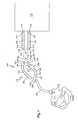
- FIG. 1is a cross-sectional side elevation view of a ventilator system according to a first embodiment
- FIG. 2is a cross-sectional side elevation view of a ventilator system according to a second embodiment
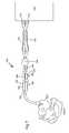
- FIG. 3is a cross-sectional side elevation view of a ventilator system according to a third embodiment
- FIG. 4is a cross-sectional side elevation view of a ventilator system according to a fourth embodiment
- FIG. 5is a cross-sectional side elevation view of a ventilator system according to a fifth embodiment
- FIG. 6is a cross-sectional side elevation view of a ventilator system according to a sixth embodiment
- FIG. 7is a cross-sectional side elevation view of a ventilator system according to a seventh embodiment.
- FIG. 8is a close-up cross-sectional side elevation view of an alternative heating wire arrangement for the system of FIG. 1 .
- the system 100includes a ventilator device 110 which can be any number of commercially available ventilators.
- the ventilator device 110has a first port 112 which serves as an inhalation port and a second port 114 which serves as an exhalation port.
- the ventilator device 110includes a first valve 120 that is associated with the inhalation port 112 and a second valve 122 that is associated with the exhalation port 114 .
- the first valve 120opens, while the second valve 122 closes so as to permit the generated gas to flow to the patient to assist in the patient's breathing.
- first valve 120assumes a closed position and the second valve 122 opens so as to permit exhaled gas to be delivered from the patient back to the ventilator.
- the first and second valves 120 , 122can therefore be in the form of one-way valves or the like.
- the ventilator system 100further includes a first conduit 130 that has a first end 132 and an opposing second end 134 .
- the first end 132can be thought of as the distal end, while the second end 134 can be thought of as a proximal end.
- the first tube 130acts as the exhalation tube of the ventilator system 100 , with the second end 134 being operatively and sealingly coupled to the exhalation port 114 .
- the first end 132is operatively and sealingly coupled to a first leg 142 of a Y-connector 140 .
- the ventilator system 100also includes a second conduit 150 that has a first end 152 and an opposing second end 154 .
- the first end 152can be though of as the distal end, while the second end 154 can be thought as the proximal end of the second conduit 150 .
- the second conduit 150acts as the inhalation tube of the ventilator system 100 .
- the second conduit 150is actually formed of two sections, namely, a first conduit section 160 and a second conduit section 170 .
- the second conduit 150is thus divided into the two sections 160 , 170 in order to permit one or more interface accessories to be placed in-line along the inhalation conduit 150 .
- the first conduit section 160is a more distal section and includes a first end 162 that is attached to a second leg 144 of the Y-connector 140 and a second end 164 that is attached to at least one device for delivering medication to the patient (means for delivering medication) 200 .
- the second section 170includes a first end 172 that is attached to the device 200 and a second end 174 is attached to a port 302 of a humidifier unit 300 .
- the humidifier unit 300is operatively connected to the ventilator device 110 by means of an interface or conduit 310 so that compressed gas is delivered from the ventilator device 110 to the humidifier unit 300 .
- the humidifier unit 300acts to heat and add moisture to the air delivered to the patient through the inhalation tube 150 .
- One means for heating the inside of the tubesis the use of heating wires or coils that are provided along a length of the tubes. More specifically, a first heating wire 320 is provided within the interior of the first conduit 130 for controlled heating thereof. The first heating wire 320 has a distal end 322 that is disposed within the interior of the first conduit 130 while a proximal end 324 is operatively connected to the humidifier unit 300 in such a way that the heating wire 320 can be controllably heated to a predetermined temperature.
- the first heating wire 320is incorporated into the inner walls of the first conduit 130 and can be arranged according to any number of different shapes or configurations.
- the first heating wire 320can be arranged in a helical manner within the interior of the first conduit 130 or it can be arranged in coiled manner or it can be arranged in any number of other arrangements so long as a significant length of the first conduit 130 can be heated to a predetermined temperature that is substantially constant along the length thereof.
- a second heating wire 330is provided within the interior of the second section 170 of the second conduit 150 for controlled heating thereof.
- the second heating wire 330has a distal end 332 that is disposed within the interior of the second section 170 proximate the first end 172 of the second section 170 , while a proximal end 334 of the second heating wire 330 is operatively connected to the humidifier unit 300 in such a way that the second heating wire 330 can be controllably heated to a predetermined temperature.
- the second heating wire 330is incorporated into the inner walls of the second section 170 of the second conduit 150 in the same manner as the first heating wire 320 is incorporated in the first conduit 130 , e.g., helical manner, coiled manner, etc.
- the first and second heating wires 320 , 330can be conventional ventilator heating wires that are available from a number of commercial sources.
- the first and second heating wires 320 , 330can be combined into a single heating wire 800 as shown in FIG. 8 where the single coiled heating wire 800 runs along both the inhalation tube 150 and the exhalation tube 130 .
- the coiled heating wireis routed along one of the tubes 130 , 150 and is then looped back and routed along the other of the tubes 130 , 150 .
- the humidifier unit 300also typically includes a temperature probe 400 that is used in combination with the first and second heating wires 320 , 330 to monitor and control the temperature within the inhalation tube 150 .
- the temperature probe 400is an elongated structure that is routed along the second section 170 of the inhalation tube 150 .
- the illustrated temperature probe 400can be a temperature probe wire that has a first end 402 and a second end 404 .
- the first end 402has a first temperature sensor 410 associated therewith, while the second end 404 has a second temperature sensor 412 associated therewith.
- the first temperature sensor 410is preferably positioned close to the connection between the device 200 and the first end 172 of the second section 170
- the second temperature sensor 412is preferably positioned close to the connection between the second end 174 and the humidifier unit 300 .
- small openingsare formed through the second section 170 near or at its ends 172 , 174 to receive, accommodate and hold the sensors 410 , 412 such that the sensing surface of the sensors 410 , 412 is placed within the interior of the second section 170 and is capable of accurately sensing the temperature therein.
- the sensors 410 , 412are disposed in openings formed in the second section, the length of the temperature probe wire 400 between the two sensors 410 , 412 is routed along the exterior of the second section 170 .
- the humidifier unit 300 and the master control unit of the ventilator device 110are constructed so that the temperature within at least the inhalation tube 150 is maintained relatively constant at a predetermined temperature.
- the temperature at the two opposing ends of the inhalation tube 150can be monitored. If the temperature of the air leaving the second section 170 is not approximately the same or is not within a threshold range compared to the temperature of the air entering the second section 170 , then the humidifier unit 300 raises the temperature within the second section 170 by increasing the energy in the second heating wire 330 .
- the Y-connector 140has a third leg 146 that is connected to a conduit 340 that leads directly to the patient. More specifically, the third leg 146 can be attached to an endotracheal or tracheostomy tube 340 that leads to the patient. As with Y-connectors, the first and second legs 142 , 144 form the open Y-end of the connector 140 and space the inhalation tube 150 apart from the exhalation tube 130 .
- the means for generating aerosolized medication 200is directly incorporated into the inhalation conduit of the circuit and therefore, unlike conventional ventilation design, the physician does not have to remove and reconfigure the inhalation tube 150 in order to incorporate the device 200 within the inhalation gas path.
- the accessory 200can be any number of different devices that are intended to deliver medication to the patient as illustrated in FIGS. 1-3 , where FIG. 2 includes one device type, FIG. 3 includes another device type; and FIG. 1 illustrates a combination of the devices of FIGS. 2 and 3 .
- the device 200is in the form of an MDI assembly which is essentially a pressurized canister that contains a medication and propellant.
- Actuation of the MDI 200results in the discharge of one dose of medication as aerosolized particles, which can be spontaneously inhaled by the patient or delivered in conjunction with positive-pressure breaths.
- a spacer device/accessory device 210should be used with the MDI device 200 .
- the spacer device 210enhances delivery by decreasing the velocity of the particles and reducing the number of large particles.
- the spacer 210is in fluid communication with the first section 160 of the second conduit 150 and therefore, the aerosolized particles that are generated by the MDI device 200 are discharged into the first section 160 where they flow into the endotracheal tube 340 to the patient.
- the MDI 200 of FIG. 3includes a nozzle with a canister stem that permit actuation of the MDI 200 .
- the means for generating aerosolized medication 200is in the form of a nebulizer 200 ′.
- aerosol delivery systems that use standard small volume nebulizers 200 ′are commonly used in acute conditions as they are relatively inexpensive; however, the medication dose used is about 10 times of that used with an MDI and hence there is potentially an increased cost without any added proven clinical benefit.
- Another difficulty with nebulizers as mentioned aboveis that the majority of the nebulized medication is wasted during exhalation since when the patient exhales, the medication can travel from the holding chamber into the exhalation tube 130 .
- the time taken to deliver the medicationis several times that of an MDI and the labor cost of respiratory therapist may outweigh the benefits of nebulizers compared with MDIs.
- the T connector 220includes a first leg 222 that is attached to the second end 164 of the first section 160 of the second conduit 150 and a second leg 224 that is attached to the first end 172 of the second section 170 of the second conduit 150 .
- a third leg 226that is typically perpendicular to an axis through the first and second legs 222 , 224 is used to connect to a source of gas 230 .
- the nebulizer 200 ′ of the present inventionuses a continuous source of gas 230 as opposed to using gas generated by the ventilator device 110 (inside source).
- the continuous source of gas 230can be an outside or external source of gas that is hooked up to the third leg 226 such that a continuous stream of gas is delivered to the nebulizer 200 ′.
- the continuous source of gas 230can be an internal source and can be in the form of an additional port or interface in the ventilator device 210 that provides a continuous flow of gas both during inhalation and exhalation.
- a nebulizer that is connected to the ventilator device 210 for its source of gasis only provided with a stream of gas during inhalation by the patient and therefore more time is needed to completely aerosolize the medication since the gas does not flow continuously.
- the present inventionpermits the physician to adjust either the location of the MDI 200 and/or nebulizer 200 ′ as a means for adjusting the strength of the dose of medication that is administered to the patient.
- the inhalation tube 150does not have to be detached and therefore, the associated risk of infection due to contamination of the inhalation tube 150 is eliminated.
- the MDI 200 or the nebulizer 200 ′was attached to the inhalation tube 150 , there was a risk of infection since this task required that the inhalation tube 150 be disconnected and thus, foreign contaminants could access the interior of the inhalation tube 150 .
- the third leg 226 of the nebulizer 200 ′can be simply capped when the MDI 200 is in use.
- the second leg 224is fluidly connected to the spacer 210 and therefore, the MDI 200 and the nebulizer 200 ′ are arranged in series with respect to one another.
- one or more of the first and second conduits 130 , 150have an adjustable length in that the conduit is formed of a material and has a construction and configuration that permits the conduit to be adjusted between a fully expanded condition where the conduit is at its maximum length and a fully retracted or compressed condition where the conduit is at is minimum length.
- the wall of the conduitcan be in the form of a bellows type structure which is easily compacted or compressed to reduce the length of the conduit, and equally can be easily expanded or stretched to increase the length of the conduit.
- FIGS. 1-3illustrate a bellows type structure for both the inhalation tube 150 and the exhalation tube 130 .
- the exhalation tube 130can optionally include a rigid section 131 that in effect partitions the exhalation tube 130 into a first section 133 that extends between the first leg 142 of the Y-connector 140 and the rigid section 131 and a second section 135 that extends between the rigid section 131 and the exhalation port 114 of the ventilation device 110 .
- the bellows type structurecan be formed from any number of different materials, including but not limited to a plastic material, a fabric or a metal material. It will be understood that while the illustrated embodiment shows both the first and second sections 133 , 135 as being expandable/compressible in nature, one or both of these sections can be a rigid structure that does not have a variable length.
- first and second sections 160 , 170 of the second conduit 150can have a variable length such that the section is positionable between a fully extended condition and a fully compact condition.
- the second conduit 150can have a bellows type structure or any other structure that permits the second conduit 150 to expand and contract so as to either increase or reduce the length of the second conduit 150 .
- the structure of each of the first and second heating wires 320 , 330is such that the heating wires easily expand and contract as either the inhalation or exhalation tube expands and contracts, respectively.
- the heating wires 320 , 330can be incorporated into the tube in a coiled manner such that that when the tube expands, the turns of the coil accommodate such movement and spread apart further from one another. Similarly, when the turns of the coil accommodate contracts of the tube by having the coils come together.
- the first section 160 of the second conduit 150acts as a reservoir for the medication as the patient both inhales and exhales since the first section 160 is disposed between the Y-connector 140 , as well as the endotracheal tube 340 , and the means for delivering medication to the patient which can be in the form of the MDI 200 and/or the nebulizer 200 ′.
- the spacer 210 of the MDI 200has a variable volume since similar to the tubes 130 , 150 , the spacer 210 is constructed so that it has a variable length as by incorporating a bellows type wall structure or the like into the spacer 210 design.
- the spacer 210can be formed of two parts that are slidable with respect to one another so as to vary the interior volume (holding chamber) defined therein. More specifically, one part can be slideably received within the other part so as to define an interior volume that can be adjusted by merely moving one part relative to the other part.
- the system 100 of the present inventionpermits the distance from the endotracheal tube 340 to the MDI 200 or the nebulizer 200 ′ to be varied.
- the present inventionprovides an inhalation circuit that can either be expanded or contracted so as to position the MDI 200 and/or the nebulizer 200 ′ at a desired distance from the endotracheal tube 340 .
- the extension of the first section 160is offset by contracting the second section 170 of the inhalation tube 150 .
- the first section 160can be constructed so that it can be extended any where from several inches up to a number of feet, such as 5 feet.
- the length of the second section 170is reduced by the same distance that the first section 160 is expanded in order to position the MDI 200 and/or nebulizer 200 ′ at a location that is further away from the Y-connector 340 . This serves to position the MDI 200 and/or nebulizer 200 ′ further away from the endotracheal tube 340 .
- the distance between the humidifier unit 300 to the endotracheal tube 340can remain substantially the same with only the ratio of the distances between the endotracheal tube 340 and the MDI 200 /nebulizer 200 ′ and between the MDI 200 /nebulizer 200 ′ and humidifier unit 300 being varied.
- the inhalation tube 150defines in part a holding chamber that has an adjustable interior volume and therefore, the volume of the inhalation tube 150 , especially the first section 160 thereof, can be advantageously varied depending upon a number of different parameters, such as the type of patient and more specifically, the weight of the patient.
- the volumecan be varied by simply either expanding or contracting the inhalation tube 150 given its structure that permits such event to occur.
- the volume of the holding chambercan be chosen between a number of different selected volumes so as to cater and customize the system 100 for the specific patient.
- the different settingscan be marked on the first section 160 or they can be otherwise conveyed to the physician who then merely manipulates the first section 160 so that the volume of the holding chamber is within the desired range.
- the settings corresponding to the volume of the holding chambercan be (1) infant; (2) young child; (3) pre-teen child; (4) teenager; (5) young adult; (6) adult; and (7) elderly.
- the settings corresponding to the volume of the holding chambercan be directly correlated to a mass size, such as (1) less than 20 pounds; (2) less than 60 pounds; (3) less than 100 pounds; (4) less than 150 pounds; (5) less than 200 pounds, etc.
- the physiciancan then manipulate the length of the first section 170 to cause the volume within the holding chamber defined thereby to be set at the desired value.
- the first section 160can be manually manipulated resulting in the interior volume of the first holding chamber either being increased or decreased.
- the first section 160can have a number of markings, settings, or graduations so that it is easy for the user to simple adjust the first section 160 relative to a fixed component, such as the Y-connector 140 until the desired marking is visible.
- a fixed componentsuch as the Y-connector 140
- the physiciancan position the MDI 200 and/or nebulizer 200 ′ further away from the Y-connector 140 and the endotracheal tube 340 by simply extending the first section 170 to a desired length.
- the first section 170can be extended any where from several inches all the way up to five feet or more depending upon the particular application.
- the extendable/contractable nature of the exhalation tube 130is designed more to accommodate the extension or contraction of the inhalation tube 150 since the exhalation tube 130 does not contain a device like the MDI 200 or nebulizer 200 ′, which is intended to moved and adjusted relative to the endotracheal tube 340 .
- the exhalation tube 130 and the sections 160 , 170 that make it upshould be constructed so that they can be extended or contracted along the same dimensional aspects as the inhalation tube 150 so that the Y-connector 340 is not strained in any direction but can maintain the position it had before manipulation of the lengths of the tube sections.
- the present inventionprovides a collapsible circuit for delivering medication to the patient through the ventilator system 100 .
- each of the extendable/contractable conduit sectionsis placed in its compact or retracted position when either the MDI 200 and/or the nebulizer 200 ′ is not in use.
- the exhalation tube 130does not necessarily have to have an extendable/contractable structure to permit the length thereof to be varied.
- the exhalation tube 130can be a standard rigid tube or conduit.
- Each of the extendable/contractable sections of the tubes 140 , 150 of the present inventioncan include a lock mechanism or the like which permits the section of the tube that is extended or contracted to be locked in a specific position.
- a lock mechanism or the likewhich permits the section of the tube that is extended or contracted to be locked in a specific position.
- a clip type devicecan be used to lock the conduit section in place once the tube is at is desired length. To change the length of the tube, the clip is simply released and the tube is adjusted to a new length and then the clip can be relocked.
- the tubes 130 , 150are described above according to one embodiment as consisting of a bellows type wall structure, it will be understood that the tube can be formed of first and second parts that are slideable with respect to one another with one part being slidably inserted into the other part. By sliding one or both of the parts, the overall length of the tube can either be increased or decreased, thereby changing the location of the MDI 200 and/or nebulizer 200 ′ relative to the endotracheal tube 340 , as well as changing the holding chamber volume. It will further be appreciated that the first and second parts can also be fitted with a locking type mechanism so as to permit the position of the first part relative to the second part to be locked in place.
- the first partcan be at least partially received in the second part such that the first part at least partially surrounds the second part, with the first part having a number of axially aligned opening formed therein. Each opening corresponds to a different interior volume setting.
- the second partcan include a biased projection that protrudes out from the exterior surface thereof and in one particular embodiment, the biased projection is a spring biased push button that can be depressed upon application of force and will return to its original biased position when the applied force is removed.
- the biased projectionWhen the second part is received in the first part, the biased projection is in a biased condition and is at least partially depressed and exerting a force against an inner surface of the first part until the projection comes into registration with one of the openings at which time, the biased nature of the projection causes the projection to fire into the opening, thereby locking the position of the first part relative to the second part.
- the projectioncan simply be depressed until it clears the first part and then the second part can be moved relative to the first part in a direction toward the next desired opening at which time the projection is received in the opening, thereby locking the two parts in a different setting with a different interior volume.
- each of the sections of the two tubes 130 , 150can be made of any number of different materials, including plastic, paper or even a metal so long as the interior volume thereof can be varied.
- the section of the tube 130 , 150can by cylindrical in shape with a series of ridges and recesses or valleys that alternate with one another so as to represent a bellows or accordion type structure.
- the tube sectioncan be supported with a metal or plastic coil that includes multiple ring structures so as to support the material that defines the body of the tube section. The distances between any two adjacent ridges can be equal as in the case of a uniform structure or the distances can be different.
- the tube sectioncan be formed of a stiff corrugated plastic that preferably does not require any additional support to maintain the shape of the tube section.
- FIGS. 4-6illustrate yet another embodiment of the present invention and in particular, a ventilator system 500 is illustrated.
- the ventilator system 500is similar to the system 100 with the exception that the system 500 does not include the humidifier unit 300 .
- the components that are identical or substantially the sameare numbered alike in both embodiments.
- the ventilator system 500includes the ventilator device 110 with ports 112 , 114 .
- a first inhalation conduit 510is provided and includes a first end 512 that is attached to a first leg 522 of a first Y-connector 520 and a second end 514 that is attached to the inhalation port 112 .
- a first exhalation conduit 530is provided and includes a first end 532 that is attached to a second leg 524 of the first Y-connector 520 and a second end 534 that is attached to the exhalation port 114 .
- a third leg 526 of the Y-connector 520is attached to one end of a heat moisture exchanger (HME) 600 that is used instead of a humidifier unit for heating and adding moisture to the compressed air.
- the HME 600is available from any number of different commercial suppliers and consists of a unit that includes a heat and moisture exchanger filter for use with mechanical ventilators to provide heat and humidity while retaining bacterial/viral contaminants.
- the HME 600is in fluid communication with both air that is inhaled by the patient as well as air that is exhaled by the patient.
- the system 500includes a second Y-connector 540 that includes first, second and third legs 542 , 544 , 546 , respectively, with the third leg 546 being attached to the other end of the HME 600 .
- a third Y-connector 550is provided and includes first, second, and third legs 552 , 554 , 556 , respectively, with the third leg 556 being connected to the endotracheal tube 340 .
- the system 500includes a second inhalation conduit 560 having a first end 562 that is attached to the first leg 552 of the third Y-connector 550 and a second end 564 opposite end 562 .
- each of the first inhalation conduit 510 and the first exhalation conduit 530has an extendable/contractable structure to permit the length thereof to be controllably varied as described in detail above with respect to the first embodiment.
- the conduits 510 , 530can have a bellows type construction or the like.
- each of the second inhalation conduit 560 and the second exhalation conduit 570is preferably formed so that they have an extendable/contractable structure, especially, the inhalation conduit 560 .
- the second exhalation conduit 570has a rigid piece 590 that divides the conduit 570 into a first conduit section 592 and a second conduit section 594 , each of which has an extendable/contractable wall structure.
- the rigid piece 590provides a means for a user to easily grasp and alter the overall length of the second exhalation conduit 570 . It will be appreciated that the rigid piece 590 can be eliminated and instead a single extendable/contractable structure can be provided.
- a first valve assembly 610is provided within the second exhalation conduit 570 .
- the first valve assembly 610is preferably a one-way valve that serves to either permit or prevent the flow of exhaled gas to the HME 600 .
- the first valve assembly 610can be disposed at the interface between the second conduit section 594 and the second leg 544 of the second Y-connector 540 . As the patient exhales, the first valve assembly 610 opens to permit the exhaled to flow into the HME 600 and conversely, when the patient inhales, the first valve assembly 610 closes to close off the second exhalation conduit 570 from the HME 600 .
- one or more devices or means for delivering aerosolized medication to the conduit 560is provided similar to the first system 100 .
- the devicecan be the MDI 200 or the nebulizer 200 ′ or a combination of both in series with respect to one another.
- FIG. 6shows the system 500 as including both the MDI 200 and the nebulizer 200 ′; however, it will be understood that the system 500 can include only one of the devices 200 , 200 ′ as shown in FIGS. 4 and 5 .
- the MDI 200includes the spacer 210 and is arranged such that the nozzle portion 202 thereof is fluidly attached to the first leg 542 of the second Y-connector 540 and the spacer 210 is attached to one leg 224 of the T connector 220 , while the other leg 222 of the T connector 220 is attached to the second end 564 of the second inhalation conduit 560 .
- the third leg 226 of the T connector 220is the one that is connected to a continuous source of gas that is used to aerosolize the medication.
- the source of gasis preferably an outside, external source of gas that is not associated with the ventilator device 110 itself; however, as previously mentioned, the ventilator device 110 can be modified to have a port that continuously supplies gas both during inhalation and exhalation.
- the third leg 226is simply capped.
- a second valve assembly 620is provided in fluid communication with the inhalation flow path.
- the second valve assembly 620is preferably a one-way valve that serves to either permit or prevent the flow of inhaled gas from the HME 600 to the endotracheal tube 340 .
- the second valve assembly 620can be disposed at the interface between the nozzle 202 of the MDI 200 and the first leg 542 of the second Y-connector 540 .
- the second valve assembly 620opens to permit the gas to flow from the HME 600 and into the device that contains the means for aerosolizing the medication and then ultimately into the endotracheal tube 340 and conversely, when the patient exhales, the second valve assembly 620 closes to close off the second inhalation conduit 560 from the HME 600 .
- the HME unitdirectly connects to the endotracheal tube 340 and the MDI or nebulizer, when used, is inserted between the endotracheal tube 340 and the HME unit.
- waste gasessuch as CO 2
- the present system 500this is accomplished by incorporating the two one way valves 610 , 620 within the system.
- the two one way valves 610 , 620serve to limit and selectively route either the exhaled gas or the inhaled gas to the HME 600 depending upon the breathing action of the patient.
- the system 500permits the distance from the endotracheal tube 340 to the MDI 200 and/or the nebulizer 200 ′ to be altered by simply either extending or contracting the second inhalation conduit 560 depending upon whether it is desired to locate the MDI 200 and/or the nebulizer 200 ′ either further away from the patient, as is the case when the patient is a larger adult, or closer to the patient, as is the case when the patient is a small child.
- the length of the exhalation conduit 570is most likely also changed in the same manner.
- the exhalation conduit 570will similarly be expanded, either by expanding the first conduit section 592 and/or the second conduit section 594 .
- FIG. 7a ventilator system 700 according to a third embodiment is illustrated.
- the system 700is very similar to the system 500 ; however, some of the conduits have been integrated with one another so as to share a common wall. In order, some of the conduits have been merged from a pair of conduit structures into a single conduit structure. For example, the first inhalation tube 510 and the first exhalation tube 530 can be merged together and share a common wall. Thus, when it is desired to change the distance from the HME 600 to the ventilator device 110 , only a single action due to the combined nature of the two conduits 510 , 530 . In the previous embodiment, each of the conduits 510 , 530 required its own adjustment and manipulation in order to change the length thereof.
- the second inhalation conduit 560 and the second exhalation conduit 570is likewise combined into a single integrated conduit structure.
- the second inhalation conduit 560shares a common wall with the first conduit section 592 of the second exhalation conduit 570 .
- the second conduit section 594is separate and spaced from and free to move relative to the MDI 200 and/or nebulizer 200 ′ which is connected between the inhalation conduit 560 and the second Y-connector 540 . This arrangement permits the spacer 210 to be able to freely extend and contract without any interference from the second conduit section 594 .
- the spacer 210While the inhalation conduit 560 and the first conduit section 592 can each extend up to a number of feet, e.g., 5 feet, the spacer 210 only extends a fraction thereof.
- the spacer 210can be constructed so that when it fully extends, the spacer 210 has a length of about 6 inches or so.
- conduitsinhalation and inhalation
- the conduitcan have any number of different cross-sectional shapes.
- the conduitcan have a circular cross-section; a rectangular cross-section, a square cross-section, an oval cross-section, etc.
- the ventilator systemincludes one or more means for delivering medication into the inhalation conduit of the patient circuit.
- an MDIcan be incorporated into the inhalation conduit for delivering a metered dose of medication or in another embodiment, the inhalation conduit can include a nebulizer T connector for attachment to an external source of gas for generating the aerosolized particles of medication.
- both the MDI and nebulizerare incorporated into the inhalation conduit and are positioned side-by-side to permit the physician to use either of these devices to deliver the medication. When the devices are not in use, each device can be capped.
Landscapes
- Health & Medical Sciences (AREA)
- Heart & Thoracic Surgery (AREA)
- Life Sciences & Earth Sciences (AREA)
- Engineering & Computer Science (AREA)
- Anesthesiology (AREA)
- Biomedical Technology (AREA)
- Emergency Medicine (AREA)
- Hematology (AREA)
- Pulmonology (AREA)
- Animal Behavior & Ethology (AREA)
- General Health & Medical Sciences (AREA)
- Public Health (AREA)
- Veterinary Medicine (AREA)
- Measurement Of The Respiration, Hearing Ability, Form, And Blood Characteristics Of Living Organisms (AREA)
- Infusion, Injection, And Reservoir Apparatuses (AREA)
Abstract
Description
Claims (27)
Priority Applications (1)
| Application Number | Priority Date | Filing Date | Title |
|---|---|---|---|
| US11/418,392US7870857B2 (en) | 2005-05-23 | 2006-05-03 | Patient interface assemblies for use in ventilator systems to deliver medication to a patient |
Applications Claiming Priority (2)
| Application Number | Priority Date | Filing Date | Title |
|---|---|---|---|
| US68414205P | 2005-05-23 | 2005-05-23 | |
| US11/418,392US7870857B2 (en) | 2005-05-23 | 2006-05-03 | Patient interface assemblies for use in ventilator systems to deliver medication to a patient |
Publications (2)
| Publication Number | Publication Date |
|---|---|
| US20060283447A1 US20060283447A1 (en) | 2006-12-21 |
| US7870857B2true US7870857B2 (en) | 2011-01-18 |
Family
ID=37452564
Family Applications (1)
| Application Number | Title | Priority Date | Filing Date |
|---|---|---|---|
| US11/418,392Expired - Fee RelatedUS7870857B2 (en) | 2005-05-23 | 2006-05-03 | Patient interface assemblies for use in ventilator systems to deliver medication to a patient |
Country Status (3)
| Country | Link |
|---|---|
| US (1) | US7870857B2 (en) |
| CA (1) | CA2609187C (en) |
| WO (1) | WO2006127257A2 (en) |
Cited By (61)
| Publication number | Priority date | Publication date | Assignee | Title |
|---|---|---|---|---|
| US20090107496A1 (en)* | 2007-10-29 | 2009-04-30 | Smiths Medical Asd, Inc. | Rainout reduction in a breathing circuit |
| US20100071695A1 (en)* | 2008-09-23 | 2010-03-25 | Ron Thiessen | Patient wye with flow transducer |
| US20100186744A1 (en)* | 2003-07-29 | 2010-07-29 | Claude Andrieux | System and process for supplying respiratory gas under pressure or volumetrically |
| US20100218765A1 (en)* | 2009-02-27 | 2010-09-02 | Nellcor Puritan Bennett Llc | Flow rate compensation for transient thermal response of hot-wire anemometers |
| US20110108031A1 (en)* | 2009-11-11 | 2011-05-12 | Carefusion 2200 Inc. | Heated conduit for respiratory humidification |
| US20110126832A1 (en)* | 2009-12-01 | 2011-06-02 | Nellcor Puritan Bennett Llc | Exhalation Valve Assembly |
| US20110126836A1 (en)* | 2009-12-01 | 2011-06-02 | Nellcor Puritan Bennett Llc | Exhalation Valve Assembly With Selectable Contagious/Non-Contagious Latch |
| US20110126834A1 (en)* | 2009-12-01 | 2011-06-02 | Nellcor Puritan Bennett Llc | Exhalation Valve Assembly With Integral Flow Sensor |
| US20110126837A1 (en)* | 2009-12-01 | 2011-06-02 | Nellcor Puritan Bennett Llc | Exhalation Valve Assembly With Integrated Filter |
| US8439037B2 (en) | 2009-12-01 | 2013-05-14 | Covidien Lp | Exhalation valve assembly with integrated filter and flow sensor |
| DE102012002632A1 (en)* | 2012-02-10 | 2013-08-14 | Dräger Medical GmbH | Ventilation system and connector system for reducing contamination |
| USD692556S1 (en) | 2013-03-08 | 2013-10-29 | Covidien Lp | Expiratory filter body of an exhalation module |
| USD693001S1 (en) | 2013-03-08 | 2013-11-05 | Covidien Lp | Neonate expiratory filter assembly of an exhalation module |
| US20140012187A1 (en)* | 2011-03-31 | 2014-01-09 | Nicolas Anthony Costovici | System for heated gas insufflation in patients |
| USD701601S1 (en) | 2013-03-08 | 2014-03-25 | Covidien Lp | Condensate vial of an exhalation module |
| US8746241B2 (en) | 2011-10-03 | 2014-06-10 | Sabrina B. Cavendish | Combination MDI and nebulizer adapter for a ventilator system |
| US8770199B2 (en) | 2012-12-04 | 2014-07-08 | Ino Therapeutics Llc | Cannula for minimizing dilution of dosing during nitric oxide delivery |
| US8839791B2 (en) | 2011-06-22 | 2014-09-23 | Breathe Technologies, Inc. | Ventilation mask with integrated piloted exhalation valve |
| US9038635B2 (en) | 2011-06-22 | 2015-05-26 | Breathe Technologies, Inc. | Ventilation mask with integrated piloted exhalation valve |
| USD731065S1 (en) | 2013-03-08 | 2015-06-02 | Covidien Lp | EVQ pressure sensor filter of an exhalation module |
| USD731048S1 (en) | 2013-03-08 | 2015-06-02 | Covidien Lp | EVQ diaphragm of an exhalation module |
| USD731049S1 (en) | 2013-03-05 | 2015-06-02 | Covidien Lp | EVQ housing of an exhalation module |
| USD736905S1 (en) | 2013-03-08 | 2015-08-18 | Covidien Lp | Exhalation module EVQ housing |
| US9144658B2 (en) | 2012-04-30 | 2015-09-29 | Covidien Lp | Minimizing imposed expiratory resistance of mechanical ventilator by optimizing exhalation valve control |
| USD744095S1 (en) | 2013-03-08 | 2015-11-24 | Covidien Lp | Exhalation module EVQ internal flow sensor |
| US20160074616A1 (en)* | 2013-04-18 | 2016-03-17 | Drägerwerk AG & Co. KGaA | Ventilation tube unit for connection to a medical ventilator as well as a ventilation system comprising the ventilator and at least one ventilation tube unit |
| US9289568B2 (en) | 2012-01-23 | 2016-03-22 | Aeon Research And Technology, Inc. | Gas delivery venturi |
| US9364624B2 (en) | 2011-12-07 | 2016-06-14 | Covidien Lp | Methods and systems for adaptive base flow |
| US9452274B2 (en) | 2011-01-20 | 2016-09-27 | Pneumoflex Systems, Llc | Metered dose atomizer |
| US9452270B2 (en) | 2011-01-20 | 2016-09-27 | Pneumoflex Systems, Llc | Nebulizer having replaceable nozzle assembly and suction line |
| US9486602B2 (en) | 2011-06-22 | 2016-11-08 | Breathe Technologies, Inc. | Ventilation mask with integrated piloted exhalation valve and method of ventilating a patient using the same |
| US9498589B2 (en) | 2011-12-31 | 2016-11-22 | Covidien Lp | Methods and systems for adaptive base flow and leak compensation |
| USD775345S1 (en) | 2015-04-10 | 2016-12-27 | Covidien Lp | Ventilator console |
| US9629971B2 (en) | 2011-04-29 | 2017-04-25 | Covidien Lp | Methods and systems for exhalation control and trajectory optimization |
| US9649458B2 (en) | 2008-09-30 | 2017-05-16 | Covidien Lp | Breathing assistance system with multiple pressure sensors |
| US9795756B2 (en) | 2012-12-04 | 2017-10-24 | Mallinckrodt Hospital Products IP Limited | Cannula for minimizing dilution of dosing during nitric oxide delivery |
| US9878121B2 (en) | 2013-03-13 | 2018-01-30 | Breathe Technologies, Inc. | Ventilation mask with heat and moisture exchange device |
| US9950135B2 (en) | 2013-03-15 | 2018-04-24 | Covidien Lp | Maintaining an exhalation valve sensor assembly |
| US10709866B2 (en) | 2014-05-13 | 2020-07-14 | Fisher & Paykel Healthcare Limited | Usability features for respiratory humidification system |
| US10828482B2 (en) | 2013-12-20 | 2020-11-10 | Fisher & Paykel Healthcare Limited | Humidification system connections |
| EP3744377A1 (en) | 2012-05-02 | 2020-12-02 | Fisher & Paykel Healthcare Limited | Respiratory humidifier communication systems |
| US10905836B2 (en) | 2015-04-02 | 2021-02-02 | Hill-Rom Services Pte. Ltd. | Manifold for respiratory device |
| US10974015B2 (en) | 2012-03-15 | 2021-04-13 | Fisher & Paykel Healthcare Limited | Respiratory gas humidification system |
| US11129956B2 (en) | 2012-04-27 | 2021-09-28 | Fisher & Paykel Healthcare Limited | Usability features for respiratory humidification system |
| US11129954B2 (en) | 2012-11-14 | 2021-09-28 | Fisher & Paykel Healthcare Limited | Zone heating for respiratory circuits |
| US11173272B2 (en) | 2014-05-02 | 2021-11-16 | Fisher & Paykel Healthcare Limited | Gas humidification arrangement |
| US11278689B2 (en) | 2014-11-17 | 2022-03-22 | Fisher & Paykel Healthcare Limited | Humidification of respiratory gases |
| US11311695B2 (en) | 2016-12-22 | 2022-04-26 | Fisher & Paykel Healthcare Limited | Medical tubes and methods of manufacture |
| US11318270B2 (en) | 2011-06-03 | 2022-05-03 | Fisher & Paykel Healthcare Limited | Medical tubes and methods of manufacture |
| US11324911B2 (en) | 2014-06-03 | 2022-05-10 | Fisher & Paykel Healthcare Limited | Flow mixers for respiratory therapy systems |
| US11351332B2 (en) | 2016-12-07 | 2022-06-07 | Fisher & Paykel Healthcare Limited | Sensing arrangements for medical devices |
| WO2022140800A1 (en)* | 2020-12-24 | 2022-06-30 | The Research Foundation For The State University Of New York | Ventilator breathing circuit with a nebulizer between the ventilator and humidifier |
| RU2782103C1 (en)* | 2022-03-24 | 2022-10-21 | федеральное государственное бюджетное учреждение "Национальный медицинский исследовательский центр онкологии" Министерства здравоохранения Российской Федерации | Method for the treatment of respiratory failure after acute respiratory distress syndrome, regardless of etiology |
| US11511069B2 (en) | 2013-09-13 | 2022-11-29 | Fisher & Paykel Healthcare Limited | Humidification system |
| US11559653B2 (en) | 2014-02-07 | 2023-01-24 | Fisher & Paykel Healthcare Limited | Respiratory humidification system |
| US11801360B2 (en) | 2013-09-13 | 2023-10-31 | Fisher & Paykel Healthcare Limited | Connections for humidification system |
| US11896767B2 (en) | 2020-03-20 | 2024-02-13 | Covidien Lp | Model-driven system integration in medical ventilators |
| US12233212B2 (en) | 2015-09-09 | 2025-02-25 | Fisher & Paykel Healthcare Limited | Zone heating for respiratory circuits |
| US12246132B2 (en) | 2014-03-17 | 2025-03-11 | Fisher & Paykel Healthcare Limited | Medical tubes for respiratory systems |
| US12296102B2 (en) | 2012-12-04 | 2025-05-13 | Fisher & Paykel Healthcare Limited | Medical tubes and methods of manufacture |
| US12364837B2 (en) | 2013-10-24 | 2025-07-22 | Fisher & Paykel Healthcare Limited | Tubing for delivery of respiratory gases |
Families Citing this family (42)
| Publication number | Priority date | Publication date | Assignee | Title |
|---|---|---|---|---|
| BRPI0416654A (en)* | 2003-11-17 | 2007-01-16 | Nektar Therapeutics | introduction of aerosol to a ventilator circuit |
| JP4652397B2 (en) | 2004-03-31 | 2011-03-16 | フィッシャー アンド ペイケル ヘルスケア リミテッド | Patient ventilation / aspiration system |
| EP2037999B1 (en) | 2006-07-07 | 2016-12-28 | Proteus Digital Health, Inc. | Smart parenteral administration system |
| NZ701722A (en) | 2006-07-28 | 2016-07-29 | Resmed Ltd | Delivery of respiratory therapy |
| NZ609725A (en) | 2007-07-31 | 2014-10-31 | Resmed Ltd | Heating element, humidifier for respiratory apparatus including heating element and respiratory apparatus |
| EP2033674A1 (en)* | 2007-09-06 | 2009-03-11 | Activaero GmbH | Inhalation device |
| EP2039387B1 (en)* | 2007-09-24 | 2012-01-11 | Covidien AG | System for conditioning respiratory gases |
| US9125979B2 (en) | 2007-10-25 | 2015-09-08 | Proteus Digital Health, Inc. | Fluid transfer port information system |
| CA2709071C (en) | 2007-12-14 | 2016-11-15 | Labogroup S.A.S. | Delivering aerosolizable food products |
| US8561606B2 (en)* | 2008-06-05 | 2013-10-22 | Carefusion 2200, Inc. | Heat and moisture exchange unit |
| US20090301476A1 (en)* | 2008-06-05 | 2009-12-10 | Neil Alex Korneff | Heat and moisture exchange unit |
| US20090301477A1 (en)* | 2008-06-05 | 2009-12-10 | Brian William Pierro | Heat and moisture exchange unit with check valve |
| DE102008039137B3 (en)* | 2008-08-21 | 2010-02-11 | Dräger Medical AG & Co. KG | Ventilator with a breathing circuit |
| US8701657B2 (en)* | 2008-08-21 | 2014-04-22 | Geno Llc | Systems for generating nitric oxide |
| CN102196837B (en)* | 2008-08-22 | 2015-09-09 | 呼吸科技公司 | Methods and devices for providing mechanical ventilation utilizing an open airway interface |
| WO2010027282A2 (en)* | 2008-09-05 | 2010-03-11 | Fisher & Paykel Healthcare Limited | Contactless power transfer in a system for providing respiratory gases to a user for therapeutic purposes |
| ITMI20090351A1 (en)* | 2009-03-10 | 2010-09-11 | Nuova Inoxtecnica S R L | APPARATUS FOR INHALATIONS AND / OR AEROSOL, PARTICULARLY FOR THERMAL AND SIMILAR WATERS. |
| IT1393213B1 (en) | 2009-03-17 | 2012-04-11 | Covidien Ag | SYSTEM FOR CONDITIONING RESPIRATORY GASES |
| US20100300446A1 (en)* | 2009-05-26 | 2010-12-02 | Nellcor Puritan Bennett Llc | Systems and methods for protecting components of a breathing assistance system |
| EP2531096A4 (en) | 2010-02-01 | 2013-09-11 | Proteus Digital Health Inc | Two-wrist data gathering system |
| BR112012019212A2 (en) | 2010-02-01 | 2017-06-13 | Proteus Digital Health Inc | data collection system |
| US20120060836A1 (en)* | 2010-09-10 | 2012-03-15 | Michael El-Shammaa | Patient circuit for improved support delivery |
| US8739788B2 (en)* | 2010-12-17 | 2014-06-03 | Vaporfection International, Inc. | Vaporizer heating assembly and method of regulating a temperature within the vaporizer heating assembly |
| EP2667919B1 (en)* | 2011-01-24 | 2021-05-26 | ResMed Pty Ltd | Humidifier |
| DE102011054131A1 (en)* | 2011-10-01 | 2013-04-04 | Hamilton Bonaduz Ag | Breathing circuit |
| EP2830694B1 (en)* | 2012-03-30 | 2021-12-08 | Fisher & Paykel Healthcare Limited | Humidification apparatus |
| US10143818B2 (en) | 2013-01-22 | 2018-12-04 | Fisher & Paykel Healthcare Limited | Dual-connector wye piece |
| EP2968808B1 (en) | 2013-03-14 | 2019-06-05 | Fisher & Paykel Healthcare Limited | Catheter mount with suction port |
| CN103800979B (en)* | 2013-06-19 | 2018-05-04 | 林信涌 | healthcare gas generator |
| NZ631077A (en)* | 2013-07-29 | 2017-09-29 | Resmed Ltd | Heat and moisture exchanger for a patient interface |
| US9744321B2 (en)* | 2013-12-16 | 2017-08-29 | General Electric Company | System and method of detecting integrity of breathing systems for safe and optimal delivery |
| WO2016043604A1 (en) | 2014-09-17 | 2016-03-24 | Fisher & Paykel Healthcare Limited | Connectors for respiratory assistance systems |
| GB2593599B (en)* | 2014-11-25 | 2021-12-22 | Fisher & Paykel Healthcare Ltd | Substance delivery arrangement for gas therapy device |
| US10245406B2 (en) | 2015-03-24 | 2019-04-02 | Ventec Life Systems, Inc. | Ventilator with integrated oxygen production |
| US10773049B2 (en) | 2016-06-21 | 2020-09-15 | Ventec Life Systems, Inc. | Cough-assist systems with humidifier bypass |
| AU2018290190B2 (en) | 2017-06-23 | 2024-06-06 | Fisher & Paykel Healthcare Limited | Connectors for respiratory assistance systems |
| US10987264B2 (en)* | 2017-07-18 | 2021-04-27 | Hill-Rom Services Pte. Ltd. | Combination respiratory therapy and mattress functionality system integrated into a patient bed |
| WO2019221852A1 (en) | 2018-05-13 | 2019-11-21 | Ahmad Samir Saleh | Portable medical ventilator system using portable oxygen concentrators |
| WO2019236899A1 (en)* | 2018-06-06 | 2019-12-12 | The Research Foundation For The State University Of New York | Ventilator circuit for breath actuated nebulizers |
| EP4081284A4 (en)* | 2019-12-26 | 2024-01-24 | Fisher & Paykel Healthcare Limited | RESPIRATORY THERAPY SYSTEM, INCUBATOR AND ITS MEDICAL RESPIRATORY GAS DISTRIBUTION DUCT |
| ES1274434Y (en)* | 2020-10-15 | 2021-10-19 | Fundacio Hospital Univ Vall Dhebron Institut De Recerca | BIOFILM FORMATION PREVENTION SYSTEM FOR RESPIRATORY MEDICAL DEVICES. |
| US20220347420A1 (en)* | 2021-05-03 | 2022-11-03 | Hill-Rom Services Pte. Ltd. | Funneled t-connector with nebulizer for use with a positive pressure ventilator |
Citations (33)
| Publication number | Priority date | Publication date | Assignee | Title |
|---|---|---|---|---|
| US3057347A (en)* | 1959-12-03 | 1962-10-09 | Prescription Drug Co Inc | Rescue breathing device |
| US4463755A (en)* | 1981-05-18 | 1984-08-07 | Terumo Corporation | Breathing circuit |
| US5263485A (en)* | 1989-09-18 | 1993-11-23 | The Research Foundation Of State University Of New York | Combination esophageal catheter for the measurement of atrial pressure |
| US5287849A (en) | 1992-07-24 | 1994-02-22 | Vortran Medical Technology, Inc. | Medicinal aerosol delivery system and method of use |
| US5349946A (en)* | 1992-10-07 | 1994-09-27 | Mccomb R Carter | Microprocessor controlled flow regulated molecular humidifier |
| US5388571A (en)* | 1987-07-17 | 1995-02-14 | Roberts; Josephine A. | Positive-pressure ventilator system with controlled access for nebulizer component servicing |
| US5482031A (en)* | 1991-09-20 | 1996-01-09 | Gibeck Respiration Ab | Arrangement for connecting a patient to a respirator, and the use of a moisture-heat-exchanger in the arrangement |
| US5628305A (en)* | 1995-09-27 | 1997-05-13 | Richard J. Melker | Universal ventilation device |
| US5640951A (en)* | 1994-03-15 | 1997-06-24 | Fisher & Paykel Limited | Humidifier conduit |
| US5791340A (en) | 1994-03-17 | 1998-08-11 | Ambu International A/S | Resuscitator |
| US5813423A (en)* | 1995-11-01 | 1998-09-29 | Kirchgeorg; John | Inhalator and/or resuscitator mask adaptable for use with an adult and child |
| US5848587A (en) | 1995-09-21 | 1998-12-15 | Medi-Nuclear Corporation, Inc. | Aerosol medication delivery system |
| US5865172A (en) | 1997-04-08 | 1999-02-02 | The Board Of Regents Of The University Of Texas System | Method and apparatus for induction of inhaled pharmacological agent by a pediatric patient |
| US6039042A (en) | 1998-02-23 | 2000-03-21 | Thayer Medical Corporation | Portable chamber for metered dose inhaler dispensers |
| US6041777A (en)* | 1995-12-01 | 2000-03-28 | Alliance Pharmaceutical Corp. | Methods and apparatus for closed-circuit ventilation therapy |
| US6078730A (en)* | 1995-11-13 | 2000-06-20 | Fisher & Paykel Limited | Heat respiratory conduit |
| US6192884B1 (en) | 1998-05-22 | 2001-02-27 | Duke University | Method and apparatus for supplemental oxygen delivery |
| US20020017302A1 (en)* | 1996-11-18 | 2002-02-14 | Fukunaga Atsuo F. | Unilimb respiratory conduit and components |
| US6427685B1 (en)* | 2000-03-27 | 2002-08-06 | Ray, Ii Philip W. | Device to facilitate the performance of cardiopulmonary resuscitation |
| US6494202B2 (en) | 2000-12-07 | 2002-12-17 | Michael W. Farmer | Inhalation therapy assembly and method |
| US20030010336A1 (en)* | 2001-07-13 | 2003-01-16 | John Vito | Extendable spacer device for metered dose inhaler |
| US6550476B1 (en) | 1998-05-21 | 2003-04-22 | Steven L. Ryder | Heat-moisture exchanger and nebulization device |
| US6622725B1 (en)* | 2000-03-31 | 2003-09-23 | Joseph A. Fisher | Rebreathing circuit to set and stabilize end tidal and arterial PCO2 despite varying levels of minute ventilation |
| US20030209246A1 (en)* | 1999-12-10 | 2003-11-13 | Gary Schroeder | Apparatus and method for respiratory tract therapy |
| US20040011364A1 (en) | 2002-07-18 | 2004-01-22 | Dhuper Sunil Kumar | Aerosol delivery apparatus III |
| US20040024372A1 (en)* | 1989-08-04 | 2004-02-05 | Grogan Jack Raymond | Dose by weight medicine dropper |
| US20040123974A1 (en) | 2002-09-16 | 2004-07-01 | Marler Gregory S. | Heat and moisture filter exchanger and method |
| US6776160B2 (en) | 2002-05-14 | 2004-08-17 | Galemed Corporation | All-in-one intake valve |
| US6799423B2 (en) | 2002-01-24 | 2004-10-05 | David L. Piekarski | Adjustable exhaust system for internal combustion engine |
| US20050039747A1 (en)* | 2001-09-24 | 2005-02-24 | Fukunaga Atsuo F. | Breathing circuits having unconventional respiratory conduits and systems and methods for optimizing utilization of fresh gases |
| US20050092325A1 (en)* | 2003-10-30 | 2005-05-05 | Dionne Cynthia A. | Aerosol flex tube |
| US20050092329A1 (en)* | 2003-10-29 | 2005-05-05 | Sta-Maria Rosalinda C. | Nasal continuous positive airway pressure cannula device and securement for infants |
| US6976488B2 (en)* | 2002-10-30 | 2005-12-20 | Allegiance Corporation | Medication bypass heat and moisture exchange unit |
- 2006
- 2006-05-03USUS11/418,392patent/US7870857B2/ennot_activeExpired - Fee Related
- 2006-05-05WOPCT/US2006/017749patent/WO2006127257A2/enactiveApplication Filing
- 2006-05-05CACA2609187Apatent/CA2609187C/ennot_activeExpired - Fee Related
Patent Citations (33)
| Publication number | Priority date | Publication date | Assignee | Title |
|---|---|---|---|---|
| US3057347A (en)* | 1959-12-03 | 1962-10-09 | Prescription Drug Co Inc | Rescue breathing device |
| US4463755A (en)* | 1981-05-18 | 1984-08-07 | Terumo Corporation | Breathing circuit |
| US5388571A (en)* | 1987-07-17 | 1995-02-14 | Roberts; Josephine A. | Positive-pressure ventilator system with controlled access for nebulizer component servicing |
| US20040024372A1 (en)* | 1989-08-04 | 2004-02-05 | Grogan Jack Raymond | Dose by weight medicine dropper |
| US5263485A (en)* | 1989-09-18 | 1993-11-23 | The Research Foundation Of State University Of New York | Combination esophageal catheter for the measurement of atrial pressure |
| US5482031A (en)* | 1991-09-20 | 1996-01-09 | Gibeck Respiration Ab | Arrangement for connecting a patient to a respirator, and the use of a moisture-heat-exchanger in the arrangement |
| US5287849A (en) | 1992-07-24 | 1994-02-22 | Vortran Medical Technology, Inc. | Medicinal aerosol delivery system and method of use |
| US5349946A (en)* | 1992-10-07 | 1994-09-27 | Mccomb R Carter | Microprocessor controlled flow regulated molecular humidifier |
| US5640951A (en)* | 1994-03-15 | 1997-06-24 | Fisher & Paykel Limited | Humidifier conduit |
| US5791340A (en) | 1994-03-17 | 1998-08-11 | Ambu International A/S | Resuscitator |
| US5848587A (en) | 1995-09-21 | 1998-12-15 | Medi-Nuclear Corporation, Inc. | Aerosol medication delivery system |
| US5628305A (en)* | 1995-09-27 | 1997-05-13 | Richard J. Melker | Universal ventilation device |
| US5813423A (en)* | 1995-11-01 | 1998-09-29 | Kirchgeorg; John | Inhalator and/or resuscitator mask adaptable for use with an adult and child |
| US6078730A (en)* | 1995-11-13 | 2000-06-20 | Fisher & Paykel Limited | Heat respiratory conduit |
| US6041777A (en)* | 1995-12-01 | 2000-03-28 | Alliance Pharmaceutical Corp. | Methods and apparatus for closed-circuit ventilation therapy |
| US20020017302A1 (en)* | 1996-11-18 | 2002-02-14 | Fukunaga Atsuo F. | Unilimb respiratory conduit and components |
| US5865172A (en) | 1997-04-08 | 1999-02-02 | The Board Of Regents Of The University Of Texas System | Method and apparatus for induction of inhaled pharmacological agent by a pediatric patient |
| US6039042A (en) | 1998-02-23 | 2000-03-21 | Thayer Medical Corporation | Portable chamber for metered dose inhaler dispensers |
| US6550476B1 (en) | 1998-05-21 | 2003-04-22 | Steven L. Ryder | Heat-moisture exchanger and nebulization device |
| US6192884B1 (en) | 1998-05-22 | 2001-02-27 | Duke University | Method and apparatus for supplemental oxygen delivery |
| US20030209246A1 (en)* | 1999-12-10 | 2003-11-13 | Gary Schroeder | Apparatus and method for respiratory tract therapy |
| US6427685B1 (en)* | 2000-03-27 | 2002-08-06 | Ray, Ii Philip W. | Device to facilitate the performance of cardiopulmonary resuscitation |
| US6622725B1 (en)* | 2000-03-31 | 2003-09-23 | Joseph A. Fisher | Rebreathing circuit to set and stabilize end tidal and arterial PCO2 despite varying levels of minute ventilation |
| US6494202B2 (en) | 2000-12-07 | 2002-12-17 | Michael W. Farmer | Inhalation therapy assembly and method |
| US20030010336A1 (en)* | 2001-07-13 | 2003-01-16 | John Vito | Extendable spacer device for metered dose inhaler |
| US20050039747A1 (en)* | 2001-09-24 | 2005-02-24 | Fukunaga Atsuo F. | Breathing circuits having unconventional respiratory conduits and systems and methods for optimizing utilization of fresh gases |
| US6799423B2 (en) | 2002-01-24 | 2004-10-05 | David L. Piekarski | Adjustable exhaust system for internal combustion engine |
| US6776160B2 (en) | 2002-05-14 | 2004-08-17 | Galemed Corporation | All-in-one intake valve |
| US20040011364A1 (en) | 2002-07-18 | 2004-01-22 | Dhuper Sunil Kumar | Aerosol delivery apparatus III |
| US20040123974A1 (en) | 2002-09-16 | 2004-07-01 | Marler Gregory S. | Heat and moisture filter exchanger and method |
| US6976488B2 (en)* | 2002-10-30 | 2005-12-20 | Allegiance Corporation | Medication bypass heat and moisture exchange unit |
| US20050092329A1 (en)* | 2003-10-29 | 2005-05-05 | Sta-Maria Rosalinda C. | Nasal continuous positive airway pressure cannula device and securement for infants |
| US20050092325A1 (en)* | 2003-10-30 | 2005-05-05 | Dionne Cynthia A. | Aerosol flex tube |
Cited By (106)
| Publication number | Priority date | Publication date | Assignee | Title |
|---|---|---|---|---|
| US20100186744A1 (en)* | 2003-07-29 | 2010-07-29 | Claude Andrieux | System and process for supplying respiratory gas under pressure or volumetrically |
| US8800557B2 (en) | 2003-07-29 | 2014-08-12 | Covidien Lp | System and process for supplying respiratory gas under pressure or volumetrically |
| US20090107496A1 (en)* | 2007-10-29 | 2009-04-30 | Smiths Medical Asd, Inc. | Rainout reduction in a breathing circuit |
| US8122882B2 (en)* | 2007-10-29 | 2012-02-28 | Smiths Medical Asd, Inc. | Rainout reduction in a breathing circuit |
| US20100071695A1 (en)* | 2008-09-23 | 2010-03-25 | Ron Thiessen | Patient wye with flow transducer |
| US9649458B2 (en) | 2008-09-30 | 2017-05-16 | Covidien Lp | Breathing assistance system with multiple pressure sensors |
| US8434479B2 (en) | 2009-02-27 | 2013-05-07 | Covidien Lp | Flow rate compensation for transient thermal response of hot-wire anemometers |
| US20100218765A1 (en)* | 2009-02-27 | 2010-09-02 | Nellcor Puritan Bennett Llc | Flow rate compensation for transient thermal response of hot-wire anemometers |
| US8905024B2 (en) | 2009-02-27 | 2014-12-09 | Covidien Lp | Flow rate compensation for transient thermal response of hot-wire anemometers |
| US20110108031A1 (en)* | 2009-11-11 | 2011-05-12 | Carefusion 2200 Inc. | Heated conduit for respiratory humidification |
| US20110126834A1 (en)* | 2009-12-01 | 2011-06-02 | Nellcor Puritan Bennett Llc | Exhalation Valve Assembly With Integral Flow Sensor |
| US8439037B2 (en) | 2009-12-01 | 2013-05-14 | Covidien Lp | Exhalation valve assembly with integrated filter and flow sensor |
| US8439036B2 (en) | 2009-12-01 | 2013-05-14 | Covidien Lp | Exhalation valve assembly with integral flow sensor |
| US8469030B2 (en) | 2009-12-01 | 2013-06-25 | Covidien Lp | Exhalation valve assembly with selectable contagious/non-contagious latch |
| US8469031B2 (en) | 2009-12-01 | 2013-06-25 | Covidien Lp | Exhalation valve assembly with integrated filter |
| US9205221B2 (en) | 2009-12-01 | 2015-12-08 | Covidien Lp | Exhalation valve assembly with integral flow sensor |
| US20110126832A1 (en)* | 2009-12-01 | 2011-06-02 | Nellcor Puritan Bennett Llc | Exhalation Valve Assembly |
| US20110126836A1 (en)* | 2009-12-01 | 2011-06-02 | Nellcor Puritan Bennett Llc | Exhalation Valve Assembly With Selectable Contagious/Non-Contagious Latch |
| US9987457B2 (en) | 2009-12-01 | 2018-06-05 | Covidien Lp | Exhalation valve assembly with integral flow sensor |
| US20110126837A1 (en)* | 2009-12-01 | 2011-06-02 | Nellcor Puritan Bennett Llc | Exhalation Valve Assembly With Integrated Filter |
| US9452274B2 (en) | 2011-01-20 | 2016-09-27 | Pneumoflex Systems, Llc | Metered dose atomizer |
| US9452270B2 (en) | 2011-01-20 | 2016-09-27 | Pneumoflex Systems, Llc | Nebulizer having replaceable nozzle assembly and suction line |
| US9095669B2 (en)* | 2011-03-31 | 2015-08-04 | Nicolas Anthony Costovici | System for heated gas insufflation in patients |
| US20140012187A1 (en)* | 2011-03-31 | 2014-01-09 | Nicolas Anthony Costovici | System for heated gas insufflation in patients |
| US9629971B2 (en) | 2011-04-29 | 2017-04-25 | Covidien Lp | Methods and systems for exhalation control and trajectory optimization |
| US10850056B2 (en) | 2011-04-29 | 2020-12-01 | Covidien Lp | Methods and systems for exhalation control and trajectory optimization |
| US11638796B2 (en) | 2011-04-29 | 2023-05-02 | Covidien Lp | Methods and systems for exhalation control and trajectory optimization |
| US11318270B2 (en) | 2011-06-03 | 2022-05-03 | Fisher & Paykel Healthcare Limited | Medical tubes and methods of manufacture |
| US12280215B2 (en) | 2011-06-03 | 2025-04-22 | Fisher & Paykel Healthcare Limited | Medical tubes and methods of manufacture |
| US8844533B2 (en) | 2011-06-22 | 2014-09-30 | Breathe Technologies, Inc. | Ventilation mask with integrated piloted exhalation valve |
| US9486602B2 (en) | 2011-06-22 | 2016-11-08 | Breathe Technologies, Inc. | Ventilation mask with integrated piloted exhalation valve and method of ventilating a patient using the same |
| US9616194B2 (en) | 2011-06-22 | 2017-04-11 | Breathe Technologies, Inc. | Ventilation mask with integrated piloted exhalation valve and method of ventilating a patient using the same |
| US8839791B2 (en) | 2011-06-22 | 2014-09-23 | Breathe Technologies, Inc. | Ventilation mask with integrated piloted exhalation valve |
| US9038634B2 (en) | 2011-06-22 | 2015-05-26 | Breathe Technologies, Inc. | Ventilation mask with integrated piloted exhalation valve |
| US9415183B2 (en) | 2011-06-22 | 2016-08-16 | Breathe Technologies, Inc. | Ventilation mask with integrated piloted exhalation valve |
| US9327092B2 (en) | 2011-06-22 | 2016-05-03 | Breathe Technologies, Inc. | Ventilation mask with integrated piloted exhalation valve |
| US9038635B2 (en) | 2011-06-22 | 2015-05-26 | Breathe Technologies, Inc. | Ventilation mask with integrated piloted exhalation valve |
| US8746241B2 (en) | 2011-10-03 | 2014-06-10 | Sabrina B. Cavendish | Combination MDI and nebulizer adapter for a ventilator system |
| US11497869B2 (en) | 2011-12-07 | 2022-11-15 | Covidien Lp | Methods and systems for adaptive base flow |
| US9364624B2 (en) | 2011-12-07 | 2016-06-14 | Covidien Lp | Methods and systems for adaptive base flow |
| US10543327B2 (en) | 2011-12-07 | 2020-01-28 | Covidien Lp | Methods and systems for adaptive base flow |
| US11833297B2 (en) | 2011-12-31 | 2023-12-05 | Covidien Lp | Methods and systems for adaptive base flow and leak compensation |
| US10709854B2 (en) | 2011-12-31 | 2020-07-14 | Covidien Lp | Methods and systems for adaptive base flow and leak compensation |
| US9498589B2 (en) | 2011-12-31 | 2016-11-22 | Covidien Lp | Methods and systems for adaptive base flow and leak compensation |
| US9498592B2 (en) | 2012-01-23 | 2016-11-22 | Aeon Research And Technology, Inc. | Modular pulmonary treatment system |
| US10525228B2 (en) | 2012-01-23 | 2020-01-07 | Aeon Research And Technology | Modular pulmonary treatment system |
| US10052451B2 (en) | 2012-01-23 | 2018-08-21 | Aeon Research And Technology, Inc. | Gas delivery venturi |
| US9289568B2 (en) | 2012-01-23 | 2016-03-22 | Aeon Research And Technology, Inc. | Gas delivery venturi |
| DE102012002632B4 (en) | 2012-02-10 | 2024-01-25 | Drägerwerk AG & Co. KGaA | Ventilation system and connector system for this to reduce contamination |
| US10456549B2 (en)* | 2012-02-10 | 2019-10-29 | Drägerwerk AG & Co. KGaA | Respiration system and connector system therefor for reducing contaminations |
| US20130206145A1 (en)* | 2012-02-10 | 2013-08-15 | Drager Medical Gmbh | Respiration system and connector system therefor for reducing contaminations |
| DE102012002632A1 (en)* | 2012-02-10 | 2013-08-14 | Dräger Medical GmbH | Ventilation system and connector system for reducing contamination |
| US12350436B2 (en) | 2012-03-15 | 2025-07-08 | Fisher & Paykel Healthcare Limited | Respiratory gas humidification system |
| US10974015B2 (en) | 2012-03-15 | 2021-04-13 | Fisher & Paykel Healthcare Limited | Respiratory gas humidification system |
| US11129956B2 (en) | 2012-04-27 | 2021-09-28 | Fisher & Paykel Healthcare Limited | Usability features for respiratory humidification system |
| US11878093B2 (en) | 2012-04-27 | 2024-01-23 | Fisher & Paykel Healthcare Limited | Usability features for respiratory humidification system |
| US9144658B2 (en) | 2012-04-30 | 2015-09-29 | Covidien Lp | Minimizing imposed expiratory resistance of mechanical ventilator by optimizing exhalation valve control |
| EP3744377A1 (en) | 2012-05-02 | 2020-12-02 | Fisher & Paykel Healthcare Limited | Respiratory humidifier communication systems |
| US11129954B2 (en) | 2012-11-14 | 2021-09-28 | Fisher & Paykel Healthcare Limited | Zone heating for respiratory circuits |
| US12053587B2 (en) | 2012-11-14 | 2024-08-06 | Fisher & Paykel Healthcare Limited | Zone heating for respiratory circuits |
| US9032959B2 (en) | 2012-12-04 | 2015-05-19 | Ino Therapeutics Llc | Cannula for minimizing dilution of dosing during nitric oxide delivery |
| US10130783B2 (en) | 2012-12-04 | 2018-11-20 | Mallinckrodt Hospital Products IP Limited | Cannula for minimizing dilution of dosing during nitric oxide delivery |
| US10556082B2 (en) | 2012-12-04 | 2020-02-11 | Mallinckrodt Hospital Products IP Limited | Cannula for minimizing dilution of dosing during nitric oxide delivery |
| US12296102B2 (en) | 2012-12-04 | 2025-05-13 | Fisher & Paykel Healthcare Limited | Medical tubes and methods of manufacture |
| US9795756B2 (en) | 2012-12-04 | 2017-10-24 | Mallinckrodt Hospital Products IP Limited | Cannula for minimizing dilution of dosing during nitric oxide delivery |
| US8770199B2 (en) | 2012-12-04 | 2014-07-08 | Ino Therapeutics Llc | Cannula for minimizing dilution of dosing during nitric oxide delivery |
| US9550039B2 (en) | 2012-12-04 | 2017-01-24 | Mallinckrodt Hospital Products IP Limited | Cannula for minimizing dilution of dosing during nitric oxide delivery |
| US10918819B2 (en) | 2012-12-04 | 2021-02-16 | Mallinckrodt Hospital Products IP Limited | Cannula for minimizing dilution of dosing during nitric oxide delivery |
| USD731049S1 (en) | 2013-03-05 | 2015-06-02 | Covidien Lp | EVQ housing of an exhalation module |
| USD744095S1 (en) | 2013-03-08 | 2015-11-24 | Covidien Lp | Exhalation module EVQ internal flow sensor |
| USD693001S1 (en) | 2013-03-08 | 2013-11-05 | Covidien Lp | Neonate expiratory filter assembly of an exhalation module |
| USD701601S1 (en) | 2013-03-08 | 2014-03-25 | Covidien Lp | Condensate vial of an exhalation module |
| USD736905S1 (en) | 2013-03-08 | 2015-08-18 | Covidien Lp | Exhalation module EVQ housing |
| USD731065S1 (en) | 2013-03-08 | 2015-06-02 | Covidien Lp | EVQ pressure sensor filter of an exhalation module |
| USD692556S1 (en) | 2013-03-08 | 2013-10-29 | Covidien Lp | Expiratory filter body of an exhalation module |
| USD731048S1 (en) | 2013-03-08 | 2015-06-02 | Covidien Lp | EVQ diaphragm of an exhalation module |
| US9878121B2 (en) | 2013-03-13 | 2018-01-30 | Breathe Technologies, Inc. | Ventilation mask with heat and moisture exchange device |
| US9950135B2 (en) | 2013-03-15 | 2018-04-24 | Covidien Lp | Maintaining an exhalation valve sensor assembly |
| US20160074616A1 (en)* | 2013-04-18 | 2016-03-17 | Drägerwerk AG & Co. KGaA | Ventilation tube unit for connection to a medical ventilator as well as a ventilation system comprising the ventilator and at least one ventilation tube unit |
| US11154682B2 (en)* | 2013-04-18 | 2021-10-26 | Drägerwerk AG & Co. KGaA | Ventilation tube unit for connection to a medical ventilator as well as a ventilation system comprising the ventilator and at least one ventilation tube unit |
| US11801360B2 (en) | 2013-09-13 | 2023-10-31 | Fisher & Paykel Healthcare Limited | Connections for humidification system |
| US11511069B2 (en) | 2013-09-13 | 2022-11-29 | Fisher & Paykel Healthcare Limited | Humidification system |
| US12053589B2 (en) | 2013-09-13 | 2024-08-06 | Fisher & Paykel Healthcare Limited | Humidification system |
| US12364837B2 (en) | 2013-10-24 | 2025-07-22 | Fisher & Paykel Healthcare Limited | Tubing for delivery of respiratory gases |
| US11826538B2 (en) | 2013-12-20 | 2023-11-28 | Fisher & Paykel Healthcare Limited | Humidification system connections |
| US10828482B2 (en) | 2013-12-20 | 2020-11-10 | Fisher & Paykel Healthcare Limited | Humidification system connections |
| US11559653B2 (en) | 2014-02-07 | 2023-01-24 | Fisher & Paykel Healthcare Limited | Respiratory humidification system |
| US12397127B2 (en) | 2014-02-07 | 2025-08-26 | Fisher & Paykel Healthcare Limited | Respiratory humidification system |
| US12246132B2 (en) | 2014-03-17 | 2025-03-11 | Fisher & Paykel Healthcare Limited | Medical tubes for respiratory systems |
| US11173272B2 (en) | 2014-05-02 | 2021-11-16 | Fisher & Paykel Healthcare Limited | Gas humidification arrangement |
| US10709866B2 (en) | 2014-05-13 | 2020-07-14 | Fisher & Paykel Healthcare Limited | Usability features for respiratory humidification system |
| US11992622B2 (en) | 2014-05-13 | 2024-05-28 | Fisher & Paykel Healthcare Limited | Usability features for respiratory humidification system |
| US11712536B2 (en) | 2014-06-03 | 2023-08-01 | Fisher & Paykel Healthcare Limited | Flow mixers for respiratory therapy systems |
| US11324911B2 (en) | 2014-06-03 | 2022-05-10 | Fisher & Paykel Healthcare Limited | Flow mixers for respiratory therapy systems |
| US11278689B2 (en) | 2014-11-17 | 2022-03-22 | Fisher & Paykel Healthcare Limited | Humidification of respiratory gases |
| US10905837B2 (en) | 2015-04-02 | 2021-02-02 | Hill-Rom Services Pte. Ltd. | Respiratory therapy cycle control and feedback |
| US11992611B2 (en) | 2015-04-02 | 2024-05-28 | Hill-Rom Services Pte. Ltd. | Respiratory therapy apparatus control |
| US10905836B2 (en) | 2015-04-02 | 2021-02-02 | Hill-Rom Services Pte. Ltd. | Manifold for respiratory device |
| USD775345S1 (en) | 2015-04-10 | 2016-12-27 | Covidien Lp | Ventilator console |
| US12233212B2 (en) | 2015-09-09 | 2025-02-25 | Fisher & Paykel Healthcare Limited | Zone heating for respiratory circuits |
| US11351332B2 (en) | 2016-12-07 | 2022-06-07 | Fisher & Paykel Healthcare Limited | Sensing arrangements for medical devices |
| US12076489B2 (en) | 2016-12-22 | 2024-09-03 | Fisher & Paykel Healthcare Limited | Medical tubes and methods of manufacture |
| US11311695B2 (en) | 2016-12-22 | 2022-04-26 | Fisher & Paykel Healthcare Limited | Medical tubes and methods of manufacture |
| US11896767B2 (en) | 2020-03-20 | 2024-02-13 | Covidien Lp | Model-driven system integration in medical ventilators |
| WO2022140800A1 (en)* | 2020-12-24 | 2022-06-30 | The Research Foundation For The State University Of New York | Ventilator breathing circuit with a nebulizer between the ventilator and humidifier |
| RU2782103C1 (en)* | 2022-03-24 | 2022-10-21 | федеральное государственное бюджетное учреждение "Национальный медицинский исследовательский центр онкологии" Министерства здравоохранения Российской Федерации | Method for the treatment of respiratory failure after acute respiratory distress syndrome, regardless of etiology |
Also Published As
| Publication number | Publication date |
|---|---|
| US20060283447A1 (en) | 2006-12-21 |
| CA2609187C (en) | 2014-07-08 |
| WO2006127257A2 (en) | 2006-11-30 |
| WO2006127257A3 (en) | 2007-09-20 |
| CA2609187A1 (en) | 2006-11-30 |
Similar Documents
| Publication | Publication Date | Title |
|---|---|---|
| US7870857B2 (en) | Patient interface assemblies for use in ventilator systems to deliver medication to a patient | |
| US12434031B2 (en) | Tracheal couplings and associated systems and methods | |
| CN102196837B (en) | Methods and devices for providing mechanical ventilation utilizing an open airway interface | |
| US9878121B2 (en) | Ventilation mask with heat and moisture exchange device | |
| US7445006B2 (en) | Aerosol inhalation system and interface accessory for use therewith | |
| JP7336150B2 (en) | Evacuation assistance system with humidifier bypass | |
| US9919124B2 (en) | Delivery adaptor for ventilation system | |
| US20150034079A1 (en) | Ventilation Mask with Integrated Piloted Exhalation Valve | |
| US20120097156A1 (en) | Positive airway pressure therapy mask humidification systems and methods | |
| US20060118113A1 (en) | System for sensing the delivery of gases to a patient | |
| CN111050830A (en) | Connectors for respiratory assistance systems | |
| JP2007501666A (en) | Patient breathing assistance method, breathing assistance device, prosthesis and catheter | |
| US8925549B2 (en) | Flow control adapter for performing spirometry and pulmonary function testing | |
| EA005171B1 (en) | Sealed back pressure breathing device | |
| US20090205652A1 (en) | Medico-surgical apparatus | |
| EP3750584B1 (en) | Active and passive humidification device for mounting in a patient ventilation circuit | |
| US20130319413A1 (en) | Reducing sound level in a respiratory gas delivery system | |
| EP4537885A2 (en) | Coupling part with integrated aerosol generator for use in a breathing circuit | |
| JPS6152708B2 (en) | ||
| JPH0120906B2 (en) |
Legal Events
| Date | Code | Title | Description |
|---|---|---|---|
| AS | Assignment | Owner name:DYNAMIC TECHNOLOGY, INC.,CONNECTICUT Free format text:ASSIGNMENT OF ASSIGNORS INTEREST;ASSIGNORS:DHUPER, SUNIL K.;D'ALO, HERBERT FRED;SIGNING DATES FROM 20091119 TO 20100426;REEL/FRAME:024483/0308 Owner name:DYNAMIC TECHNOLOGY, INC., CONNECTICUT Free format text:ASSIGNMENT OF ASSIGNORS INTEREST;ASSIGNORS:DHUPER, SUNIL K.;D'ALO, HERBERT FRED;SIGNING DATES FROM 20091119 TO 20100426;REEL/FRAME:024483/0308 | |
| AS | Assignment | Owner name:AEON RESEARCH AND TECHNOLOGY, INC.,NEW YORK Free format text:ASSIGNMENT OF ASSIGNORS INTEREST;ASSIGNOR:DYNAMIC TECHNOLOGY, INC.;REEL/FRAME:024611/0642 Effective date:20100628 Owner name:AEON RESEARCH AND TECHNOLOGY, INC., NEW YORK Free format text:ASSIGNMENT OF ASSIGNORS INTEREST;ASSIGNOR:DYNAMIC TECHNOLOGY, INC.;REEL/FRAME:024611/0642 Effective date:20100628 | |
| FPAY | Fee payment | Year of fee payment:4 | |
| AS | Assignment | Owner name:AEON RESEARCH AND TECHNOLOGY, INC., NEW YORK Free format text:CORRECTIVE ASSIGNMENT TO CORRECT THE ASSIGNEE NAME INSIDE THE ASSIGNMENT DOCUMENT PREVIOUSLY RECORDED AT REEL: 024611 FRAME: 0642. ASSIGNOR(S) HEREBY CONFIRMS THE ASSIGNMENT;ASSIGNOR:DYNAMIC TECHNOLOGY, INC.;REEL/FRAME:037472/0430 Effective date:20100628 | |
| FEPP | Fee payment procedure | Free format text:MAINTENANCE FEE REMINDER MAILED (ORIGINAL EVENT CODE: REM.); ENTITY STATUS OF PATENT OWNER: SMALL ENTITY | |
| LAPS | Lapse for failure to pay maintenance fees | Free format text:PATENT EXPIRED FOR FAILURE TO PAY MAINTENANCE FEES (ORIGINAL EVENT CODE: EXP.); ENTITY STATUS OF PATENT OWNER: SMALL ENTITY | |
| STCH | Information on status: patent discontinuation | Free format text:PATENT EXPIRED DUE TO NONPAYMENT OF MAINTENANCE FEES UNDER 37 CFR 1.362 | |
| FP | Lapsed due to failure to pay maintenance fee | Effective date:20190118 | |
| AS | Assignment | Owner name:RAPID7, INC., MASSACHUSETTS Free format text:ASSIGNMENT OF ASSIGNORS INTEREST;ASSIGNOR:DIVVY CLOUD CORPORATION;REEL/FRAME:068624/0318 Effective date:20200524 |