US7870852B2 - Pneumatically powered projectile launching device - Google Patents
Pneumatically powered projectile launching deviceDownload PDFInfo
- Publication number
- US7870852B2 US7870852B2US11/624,895US62489507AUS7870852B2US 7870852 B2US7870852 B2US 7870852B2US 62489507 AUS62489507 AUS 62489507AUS 7870852 B2US7870852 B2US 7870852B2
- Authority
- US
- United States
- Prior art keywords
- bolt
- chamber
- working surface
- gas
- compressed gas
- Prior art date
- Legal status (The legal status is an assumption and is not a legal conclusion. Google has not performed a legal analysis and makes no representation as to the accuracy of the status listed.)
- Active, expires
Links
- 239000003550markerSubstances0.000claimsdescription19
- 238000010304firingMethods0.000description5
- CURLTUGMZLYLDI-UHFFFAOYSA-NCarbon dioxideChemical compoundO=C=OCURLTUGMZLYLDI-UHFFFAOYSA-N0.000description4
- 230000007246mechanismEffects0.000description4
- 239000000463materialSubstances0.000description3
- 238000003860storageMethods0.000description3
- 229910002092carbon dioxideInorganic materials0.000description2
- 239000001569carbon dioxideSubstances0.000description2
- 230000000694effectsEffects0.000description2
- 238000004519manufacturing processMethods0.000description2
- 238000010926purgeMethods0.000description2
- 238000004891communicationMethods0.000description1
- 238000009826distributionMethods0.000description1
- 239000007788liquidSubstances0.000description1
- 239000002184metalSubstances0.000description1
- 239000008188pelletSubstances0.000description1
- 238000007789sealingMethods0.000description1
Images


Classifications
- F—MECHANICAL ENGINEERING; LIGHTING; HEATING; WEAPONS; BLASTING
- F41—WEAPONS
- F41B—WEAPONS FOR PROJECTING MISSILES WITHOUT USE OF EXPLOSIVE OR COMBUSTIBLE PROPELLANT CHARGE; WEAPONS NOT OTHERWISE PROVIDED FOR
- F41B11/00—Compressed-gas guns, e.g. air guns; Steam guns
- F41B11/70—Details not provided for in F41B11/50 or F41B11/60
- F41B11/73—Sealing arrangements; Pistons
- F—MECHANICAL ENGINEERING; LIGHTING; HEATING; WEAPONS; BLASTING
- F41—WEAPONS
- F41B—WEAPONS FOR PROJECTING MISSILES WITHOUT USE OF EXPLOSIVE OR COMBUSTIBLE PROPELLANT CHARGE; WEAPONS NOT OTHERWISE PROVIDED FOR
- F41B11/00—Compressed-gas guns, e.g. air guns; Steam guns
- F41B11/70—Details not provided for in F41B11/50 or F41B11/60
- F41B11/72—Valves; Arrangement of valves
- F41B11/721—Valves; Arrangement of valves for controlling gas pressure for both firing the projectile and for loading or feeding
Definitions
- An embodiment of the inventionis directed to pneumatically powered projectile launching devices, such as paintball markers. Other embodiments are also described.
- Guns using pneumatic force to propel a projectileare well known.
- a volume of compressed gassuch as carbon dioxide gas
- the projectileis spherical and frangible, and contains a colored liquid or gel material which leaves a mark on the target upon the projectile's impact with the target.
- Such gunsare referred to as paintball markers.
- a typical paintball marker designhas a body which houses and interconnects several pneumatic components.
- the bodymay contain a number of bores that communicate with each other.
- One boremay contain and distribute pressurized gas.
- Another bore(that is parallel to the other) may contain a compressed gas storage chamber, as well as mechanisms for filling the storage chamber with gas and releasing gas from the storage chamber to fire a projectile.
- Yet another boremay contain mechanisms for loading and launching the projectile.
- Electrically operated pneumatic flow distribution devicesare added that are sequentially energized by a timing circuit, to enable the loading of a projectile and to release compressed gas to fire the projectile.
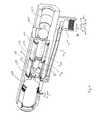
- FIG. 1is a cutaway, elevation view of a pneumatically powered projectile launching device in accordance with an embodiment of the invention.
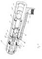
- FIG. 2is a cutaway, elevation view of another embodiment of the invention.
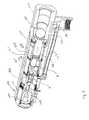
- FIG. 3is a cutaway, elevation view of yet another embodiment of the invention.
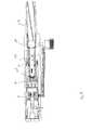
- FIG. 4is an exploded view of some of the parts of the embodiment of FIG. 3 .
- FIGS. 5-8show different stages of a launching sequence for the embodiment of FIG. 3 , including movement of the piston, bolt and projectile.
- FIG. 1is a cutaway, elevation view of such a device, in accordance with an embodiment of the invention.
- the devicehas a body 101 in which is located a gas chamber B (also referred to as the forward chamber or the main gas chamber).
- the body 101may be a single piece of metal or other suitable material in which openings have been formed, and into which internal components have been inserted, to define the chamber B (and any gas flow passages or channels described below).
- the chamber Bis sized to hold a volume of compressed gas needed to launch a projectile 114 .
- An opening 118to fill the chamber B with compressed gas, is located, in this example, at the rear end of the chamber B. At its forward end, opposite the rear end, there is another opening 117 through which a bolt 103 extends.
- the size and shape of this opening 117is designed to mate with the outside surface of a middle portion 104 of the bolt 103 , to yield an interface that prevents meaningful leakage of compressed gas from the chamber B past the outside surface of the bolt 103 .
- the interfaceallows the bolt to move back and forth in its longitudinal direction, as described below, which in effect changes the volume of the chamber B.
- the bolt 103has a backward facing working surface 120 .
- a working surface as understood hereis generally transverse to a longitudinal axis of the component (here, the bolt 130 ), but the entire surface is not required to be perpendicular to the longitudinal axis.
- the working surface of a componentis designed to be subject to pneumatic pressure, from a compressed gas, for moving the component.
- a breech regionis located forward of the bolt and into which the projectile 114 has seated.
- the projectile 114passes from outside the body 101 , through an opening above the bolt 103 , and into the breech region, once the bolt has moved back to its full backward position.
- This seating of the projectile 114may be accomplished by a projectile magazine that is feeding projectiles sequentially into the breech region.
- a barrel 113 of the deviceis located forward of the breech region and into which the breech region opens.
- Launching the projectile 114calls for the bolt 103 moving forward to push the projectile 114 from the breech region into the barrel 113 , and then, through application of pneumatic force of the released compressed gas, shooting the projectile out of the barrel 113 in the forward direction.
- An example configuration of the bolt that can achieve this launching sequenceis described next.
- the bolt 103has a back portion 131 in which the backward facing working surface 120 is formed at the rear end.
- the back portion in this exampleis cylindrical.
- a middle portion 104which has an outer diameter that is greater than that of the back portion 131 .
- the length of the middle portion 104is designed in view of the size of the breech region and the projectile 114 .
- the bolt 103also has a front portion 132 having a greater outer diameter than that of the middle portion 104 .
- One or more gas passages or gas channels 128are formed in the front portion 132 , where at least the majority of each of the passages 128 is inside the bolt and not on its longitudinal, outside surface (as indicated by the dotted lines). Each passage connects an opening in a forward facing surface of the front portion 132 , to an opening in a backward facing surface of the bolt that is located between, or at the junction of, the middle and front portions of the bolt.
- the device in FIG. 1also has a gas valve 121 located within the body 101 , to selectively release compressed gas into the chamber B.
- the opening 118 in the rear end of the chamber Bmay be part of the valve 121 , and in particular its outlet.
- An inlet of the valve 121may be connected to a compressed gas supply by a channel 123 .
- the supplymay be, for example, a carbon dioxide canister with a pressure regulator (not shown), which supplies the needed compressed gas through a gas fitting 124 .
- the fitting 124may be fixed to the body 101 and is in communication with the channel 123 .
- FIG. 1shows an example of such a combination, for holding a vertical gas source below the body 101 .
- Other types of compressed gas supplies and fitting arrangementsmay be used.
- the valve 121may be normally closed, in this example thereby closing off the chamber B when the middle portion 104 of the bolt 103 is in position against the opening 117 as shown.
- the valve 121may then be manually actuated by a trigger being pulled by the user of the device.
- the valve 121may be a solenoid valve that opens in response to a timed, electrical trigger signal.
- FIG. 2 described belowillustrates yet another alternative for the valve 121 .
- the compressed gasonce released into the chamber B (by the valve 121 responding to the trigger being squeezed), performs at least two things. First, it applies pressure on the backward facing working surface 120 of the bolt 103 to move the bolt forward. Then, once the bolt 103 has moved sufficiently forward, such that the rear end of its middle portion 104 clears the opening 117 (and the smaller diameter back portion 131 enters the opening 117 ), the compressed gas passes through the opening 117 and then through one or more passages 128 in the bolt, to then pneumatically force the projectile 114 to leave the device through the barrel 113 .
- This two-stage launch sequencemakes efficient use of the compressed gas. It can be implemented in a paintball marker, for example, by the configuration of the bolt 103 , breech region, and barrel shown in FIG. 3 (to be described later below).
- the boltmay be biased backwards, by a mechanical spring (not shown) that has the force needed to push or pull the bolt back (once the pressure in chamber B has dropped to a sufficiently low level).
- FIG. 3shows another mechanism that can be used to move the bolt back automatically, and without using a mechanical spring.
- FIG. 2another embodiment of the invention is shown, by a cutaway elevation view.
- This embodimentmay use most of the elements described above in connection with FIG. 1 (or other suitable elements), and in addition has a particular type of valve 121 .
- a gas chamber A(also referred to here as the back chamber) is located within the body 101 , in this example directly behind the chamber B. Chamber A is also sized to hold a volume of compressed gas that is needed to launch the projectile 114 .
- a piston and its sleevealso referred to as a pilot
- the pistonis movable along it's longitudinal axis between a dosed position and forward to an open position.
- the piston 106is to selectively close and open a gas path that connects chamber A with chamber B, where this gas path may include opening 118 of chamber B (see FIG. 1 ).
- the volume of chamber Athat is, the volume which is available within the body 101 (exclusive of the channel 123 that is used to fill the chamber A from a supply) to hold the compressed gas, is no less than 80% of the available volume in chamber B (e.g., the available volume in chamber B with the bolt 103 in its full backward position as shown). This provides the needed pneumatic force to launch the projectile 114 .
- the piston 106has a forward facing first working surface 204 , and a backward facing second working surface 205 , where the latter is spaced forward of the working surface 204 as shown.
- the piston 106also has a forward facing third working surface 206 that is spaced forward of the surface 205 as shown.
- the surface 206is located within chamber B, while the surfaces 204 and 205 are located within chamber A.
- An electromechanical transducer 210is also located in the body 101 , in this example directly behind and in line with the longitudinal axis of the piston 106 , and is coupled to move the piston 106 forward to the open position in response to a launch trigger signal.
- the piston's forward facing first working surface 204has essentially equal area as the backward facing second working surface 205 .
- Thistogether with a pair of o-ring seals, in this example fitted to the outside surface of the piston 106 inside the sleeve, one behind the surface 204 and one in front the surface 205 , which prevent meaningful leakage from chamber A, help maintain the piston 106 in position even if the device were to, for example, be dropped by the user and hit the ground.
- the equal force applied in the forward and backward directions (on the two working surfaces 204 , 205 ) simultaneously by the compressed gas (received through the channel 123 )tends not to apply any net longitudinal force to the piston 106 .
- Forward movement of the piston 106in this embodiment, is therefore only caused by the transducer 210 being actuated, in response to an electrical launch signal (trigger signal), pushing the piston 106 from behind the working surfaces 204 , 205 .
- Opening the gas pathcauses the release of compressed gas from chamber A into chamber B.
- pressure on the forward facing working surface 206 of the pistonincreases and eventually pushes the piston 106 back to its closed position (closing the opening 118 , see FIG. 1 ).
- the area of the surface 206should thus be designed to allow enough force to be generated by the compressed gas in chamber B, to overcome any friction between the seals of the piston 106 and the surrounding piston sleeve.
- the transducer 210should be designed and operated so that the piston 106 , once it has moved forward to the open position, is essentially released and is thereafter free to move backwards in response to the expanding gas and mounting pressure in chamber B. This allows the off/on/off pulsing of the piston 106 , to release a certain volume of the compressed gas into the chamber B. Note that once the piston 106 has moved back to its closed position, chamber A may again refill with compressed gas via channel 123 .
- FIG. 3a cutaway, elevation view of yet another embodiment of the invention is shown.
- the body 101is designed with a single, round bore in which the transducer 210 , chamber A, chamber B, and a further chamber, chamber C, are located side-by-side in that sequence.
- FIG. 4shows an exploded view or parts list of some of the components that fit on or inside of the single bore within the body. These parts are designed to fit into the bore by sliding into position within the bore and be fixed in that position.
- O-ring sealsshould be fitted either around the outside surface or the inside surface of a component, if needed to prevent meaningful leakage of the compressed gas across component interfaces.
- Components in this embodimentinclude a back chamber housing 406 including a piston sleeve in which the piston 106 is constrained to only move in its longitudinal direction, a front chamber housing 408 in which the front chamber (chamber B) is located, and a bolt sleeve or bolt housing 409 that constrains the bolt 103 to only move in its longitudinal direction.
- FIG. 4also shows an example of the components used in the transducer 210 , including a coil housing 412 , coil assembly 413 , coil housing plug 414 , and magnet 415 . The manner in which these components operate relative to each other will be described further below.
- a different mechanismis used for moving back or recoiling the bolt 103 (to enable the loading of the next projectile 114 ).
- the bolt 103in this case extends into a chamber C that is in front of chamber B.
- the outside surface of the bolt 103is configured with a forward facing working surface 305 .
- the working surface 305is formed in the front portion 132 of the bolt (see FIG. 4 ).
- the chamber C in this exampleis defined by the outside surface of the front portion 132 , the forward facing working surface 305 , and the inside wall of the bolt sleeve 409 .
- an o-ring seal 321 behind the surface 305 , and an o-ring seal 323 in frontmay be provided to prevent meaningful leakage of compressed gas from the chamber C.
- the seal 321is fitted into a corresponding groove in the outside surface of the bolt 103
- the seal 323is fitted to the inside surface of the bolt sleeve 409 .
- Other arrangements for sealing the chamber Care possible.
- the surface 305 in effectbecomes a moveable wall of the chamber C, where the available volume of chamber C changes in response to the bolt moving forwards and backwards.
- the chamber Cis to hold a volume of compressed gas needed to apply pressure on the forward facing working surface 305 , to move the bolt 305 to its full backward position.
- the source for this compressed gasmay be the same as that provided through the fitting 124 , via a gas channel 333 formed, in this example, within the body 101 .
- chambers A and Care at the same pressure of compressed gas, by virtue of being run off the same pressure regulator.
- chambers A and Ccan be run at different pressures, perhaps using multiple regulators.
- the forward facing working surface 305 of the boltshould be sized or balanced, relative to the backward facing working surface 120 of the bolt (which is used to do the work in moving the bolt forward), to not resist too much the forward movement of the bolt when launching the projectile, yet enable a sufficiently rapid recoil of the bolt to, for example, support rapid, semiautomatic firing.
- the manner in which compressed gas is routed to the chamber C as depicted in FIG. 3puts essentially constant pressure on the forward facing working surface 305 , during normal operation of the paintball marker.
- the pressure on the surface 305remains essentially unchanged during the following interval: between when a) the bolt is moved to its full backward position and a paintball is loaded into the breech region of the marker, and b) the bolt is moved forward to push the loaded paintball into the barrel of the marker and compressed gas released from chamber B passing through the bolt launches the paintball from the barrel.
- This constant pressuremay also be applied during multiple, consecutive firing sequences. This aspect of the invention obviates the need for biasing the bolt using a mechanical spring for instance.
- the reference to constant heredepends on the output of the pressure regulator (if any) that feeds the gas channel 333 .
- the area of the backward facing working surface 120 of the boltshould be greater than that of the forward facing working surface 305 so that the compressed gas being released into chamber B can efficiently launch the paintball 114 without encountering too much resistance in the opposite direction.
- the transducer 210has a coil assembly 413 that receives an electrical signal in response to the user squeezing a trigger of the device. This signal energizes the coil which in turn causes a “floating” pin 309 to be moved forward, thereby pushing the piston 106 forward into the open position. Once de-energized, the magnet 415 behind the pin 309 uses magnetic force to pull the pin 309 back, and keeps the pin 309 in its full backward position until the next trigger cycle. Other arrangements for the transducer 210 are possible.
- the rear end of the piston 106may extend back into the coil assembly such that no separate pin is needed.
- the piston 106can alternatively be biased by a mechanical spring in its backward (closed) position.
- the surfaces 204 , 205 of the pistonhave a sufficiently different area (including different diameters) that allows the piston to remain in the closed position, without having to use a mechanical spring and without having to attach the piston to the pin 309 .
- surface 204were larger than surface 205 , then whenever the device is put under pressure, i.e. in this case the chamber A is filled with compressed gas, the piston will be kept in its default, closed position until the transducer 210 is actuated by a trigger signal.
- the surfaces 204 , 205may be designed so that the piston remains closed (when the pressure is on in chamber A), even if the user allows the device to fall to the ground by accident.
- FIGS. 5-8show different states of the device of FIG. 3 , in an example launching sequence.
- FIG. 5this figure shows the device with the bolt 103 in its full backward or cocked position, with a projectile 114 seated in the breech region in front of the bolt.
- the figurealso shows chamber A, located around the piston housing, being shaded to indicate that it is full of compressed gas.
- Chamber Bis empty of the compressed gas
- chamber Clocated in the gap between the bolt 103 and the bolt sleeve, is filled with compressed gas.
- Chamber Ais closed by the piston 106 in the position shown.
- the pressure in chamber Chas pushed the bolt to its back position and holds the bolt there, thereby allowing the projectile 114 to seat in the breech of the paintball marker.
- the coil pin 309is under control of an electronic circuit that responds to the squeezing of the trigger.
- a magnet 415 housed in the coil plug 114which in this case threadingly engages the body to hold the components against each other, is provided to recall the pin 309 back to the position shown in FIG. 5 (once the coil is de-energized following the trigger having been pulled).
- a circuit boardIn response to pulling the trigger, a circuit board sends current though the coil and energizes the coil. The point in time at which this current is sent to the coil can be adjusted.
- the coilonce energized moves the coil pin 309 forward which, in this embodiment, after closing a small gap, pushes against the rear end of the piston 106 . This in turn causes the piston 106 to progress further into chamber B, thereby opening the gas passage between chamber A and chamber B.
- FIG. 6This is depicted in FIG. 6 , as the compressed gas is released into the chamber B. Pressure in chamber B rises towards that of chamber A, and as the chamber B fills up, the pressure in that chamber is pushing on the backward facing working surface of the bolt 103 , as shown by the arrow.
- the electrical signal that has energized the coilis now cut off, and the piston 106 is free to move back in response to pressure on its forward facing working surface 206 .
- the piston 106thus moves back to its closed position, closing the passage between chamber A and chamber
- FIG. 7shows that as the bolt 103 moves forward, it pushes the projectile 114 from the breech region towards the barrel 113 .
- the boltcontinues to move forward under pressure of chamber B to close the breech and load the paintball into the barrel 113 .
- the bolt 103which has been designed with a smaller back portion 131 , allows the compressed gas in chamber B to expel, as depicted in FIG. 8 , into a space defined by the bolt housing 409 , where this space is in front of the opening formed in the front chamber housing 408 .
- chamber Bis open once again, such that the compressed gas therein is released into the space that is adjacent in the bolt sleeve 409 , and then moves through the gas passages 128 that are within the bolt 103 .
- the chamber Bis now empty of compressed gas such that the pressure in chamber C forces the forward facing working surface of the bolt 103 to move backwards, thereby moving the bolt 103 to its rear most position.
- the markeris now ready for a new launch cycle, with a new projectile being seated in the breech region.
- pneumatic forcee.g., generated using compressed gas from a relatively small canister for a paintball marker, not shown
- pneumatic forceis used in the embodiment of the invention shown in FIG. 3 to both recoil the bolt and move the pilot that starts the launch sequence
- there is essentially no wasted gasFor example, there is no need to purge any chambers into the atmosphere (other than the volume of gas that actually propels the paintball) in order to recoil the bolt. This also saves a certain amount of time that would otherwise be needed to purge a chamber. Accordingly, a tangible benefit in terms of both gas efficiency and greater speed of operation for firing a sequence of two or more shots, may be achieved.
- the inventionis not limited to the specific embodiments described above.
- the coil assembly 413 and piston 106could be positioned vertically within a trigger frame of the device, rather than horizontally, or in-line, with the chamber B and the bolt 103 . This may help shorten the length of the device. Accordingly, other embodiments are within the scope of the claims.
Landscapes
- Engineering & Computer Science (AREA)
- General Engineering & Computer Science (AREA)
- Toys (AREA)
Abstract
Description
Claims (23)
Priority Applications (2)
| Application Number | Priority Date | Filing Date | Title |
|---|---|---|---|
| US11/624,895US7870852B2 (en) | 2007-01-19 | 2007-01-19 | Pneumatically powered projectile launching device |
| US13/008,725US8286621B2 (en) | 2007-01-19 | 2011-01-18 | Pneumatically powered projectile launching device |
Applications Claiming Priority (1)
| Application Number | Priority Date | Filing Date | Title |
|---|---|---|---|
| US11/624,895US7870852B2 (en) | 2007-01-19 | 2007-01-19 | Pneumatically powered projectile launching device |
Related Child Applications (1)
| Application Number | Title | Priority Date | Filing Date |
|---|---|---|---|
| US13/008,725DivisionUS8286621B2 (en) | 2007-01-19 | 2011-01-18 | Pneumatically powered projectile launching device |
Publications (2)
| Publication Number | Publication Date |
|---|---|
| US20080173291A1 US20080173291A1 (en) | 2008-07-24 |
| US7870852B2true US7870852B2 (en) | 2011-01-18 |
Family
ID=39640063
Family Applications (2)
| Application Number | Title | Priority Date | Filing Date |
|---|---|---|---|
| US11/624,895Active2029-05-27US7870852B2 (en) | 2007-01-19 | 2007-01-19 | Pneumatically powered projectile launching device |
| US13/008,725Expired - Fee RelatedUS8286621B2 (en) | 2007-01-19 | 2011-01-18 | Pneumatically powered projectile launching device |
Family Applications After (1)
| Application Number | Title | Priority Date | Filing Date |
|---|---|---|---|
| US13/008,725Expired - Fee RelatedUS8286621B2 (en) | 2007-01-19 | 2011-01-18 | Pneumatically powered projectile launching device |
Country Status (1)
| Country | Link |
|---|---|
| US (2) | US7870852B2 (en) |
Cited By (6)
| Publication number | Priority date | Publication date | Assignee | Title |
|---|---|---|---|---|
| US20110114072A1 (en)* | 2007-01-19 | 2011-05-19 | Kingman International Corporation | Pneumatically powered projectile launching device |
| US20140026878A1 (en)* | 2012-07-30 | 2014-01-30 | Danial Jones | Pneumatically timed control unit for a gas operated projectile launching device |
| USD699303S1 (en)* | 2012-09-25 | 2014-02-11 | Todd F. Coulter | Pneumatic gun bolt |
| USD745936S1 (en)* | 2013-09-30 | 2015-12-22 | Todd F. Coulter | Pneumatic gun bolt |
| US9752846B1 (en)* | 2015-02-23 | 2017-09-05 | Lurker Paintball, LLC | Pneumatic launching assembly |
| US9797678B2 (en)* | 2016-09-02 | 2017-10-24 | Jui-Fu Tseng | Electromagnetic valve activated firing mechanism of airsoft gun |
Families Citing this family (24)
| Publication number | Priority date | Publication date | Assignee | Title |
|---|---|---|---|---|
| US7451755B2 (en)* | 2004-07-16 | 2008-11-18 | Kee Action Sports | Gas governor, snatch grip, and link pin for paintball gun |
| EP1999883A4 (en) | 2006-03-14 | 2013-03-06 | Divx Llc | Federated digital rights management scheme including trusted systems |
| US20090095271A1 (en)* | 2007-10-12 | 2009-04-16 | Smart Parts, Inc. | Paintball gun with rearwardly removable pneumatic assembly |
| US8578922B1 (en)* | 2008-07-17 | 2013-11-12 | Christopher George Granger | Automatic airgun method and apparatus |
| US8781122B2 (en) | 2009-12-04 | 2014-07-15 | Sonic Ip, Inc. | Elementary bitstream cryptographic material transport systems and methods |
| US9080840B2 (en) | 2010-06-30 | 2015-07-14 | Taser International, Inc. | Electronic weaponry with canister for electrode launch |
| US9247312B2 (en) | 2011-01-05 | 2016-01-26 | Sonic Ip, Inc. | Systems and methods for encoding source media in matroska container files for adaptive bitrate streaming using hypertext transfer protocol |
| US9467708B2 (en) | 2011-08-30 | 2016-10-11 | Sonic Ip, Inc. | Selection of resolutions for seamless resolution switching of multimedia content |
| US8964977B2 (en) | 2011-09-01 | 2015-02-24 | Sonic Ip, Inc. | Systems and methods for saving encoded media streamed using adaptive bitrate streaming |
| US8909922B2 (en) | 2011-09-01 | 2014-12-09 | Sonic Ip, Inc. | Systems and methods for playing back alternative streams of protected content protected using common cryptographic information |
| US20140026877A1 (en)* | 2012-07-26 | 2014-01-30 | Bourke Grundy | Pressure sensing in paintball markers |
| US9313510B2 (en) | 2012-12-31 | 2016-04-12 | Sonic Ip, Inc. | Use of objective quality measures of streamed content to reduce streaming bandwidth |
| US9191457B2 (en) | 2012-12-31 | 2015-11-17 | Sonic Ip, Inc. | Systems, methods, and media for controlling delivery of content |
| US9094737B2 (en) | 2013-05-30 | 2015-07-28 | Sonic Ip, Inc. | Network video streaming with trick play based on separate trick play files |
| US9866878B2 (en) | 2014-04-05 | 2018-01-09 | Sonic Ip, Inc. | Systems and methods for encoding and playing back video at different frame rates using enhancement layers |
| US20160146567A1 (en)* | 2014-11-24 | 2016-05-26 | William Nachefski | Efficient high-velocity compressed gas-powered gun |
| US10113829B2 (en)* | 2014-11-24 | 2018-10-30 | William S. Nachefski | Efficient high-velocity compressed gas-powered gun |
| US10955216B2 (en)* | 2018-10-30 | 2021-03-23 | Tricord Solutions, Inc. | Projectile launching apparatus with magnetic bolt valve |
| US11536391B2 (en)* | 2019-10-08 | 2022-12-27 | War Machine, Inc. | Pneumatic actuation valve assembly |
| US11203047B1 (en)* | 2020-10-20 | 2021-12-21 | Diversitech Corporation | Projectile launcher |
| US12078444B2 (en) | 2021-09-27 | 2024-09-03 | War Machine, Inc. | Gas projectile platform and assembly |
| US11933577B1 (en)* | 2023-04-28 | 2024-03-19 | Aaron Robinson | Water assisted launching cannon |
| CN117053624B (en)* | 2023-08-08 | 2025-10-03 | 南京理工大学 | Fire channel area gas guide control double chamber device |
| US20250271235A1 (en)* | 2024-02-28 | 2025-08-28 | United States Of America, As Represented By The Secretary Of The Navy | Pneumatic Rifle for Alternative Ammunition |
Citations (14)
| Publication number | Priority date | Publication date | Assignee | Title |
|---|---|---|---|---|
| US5613483A (en)* | 1995-11-09 | 1997-03-25 | Lukas; Michael A. | Gas powered gun |
| US5769066A (en)* | 1997-04-01 | 1998-06-23 | Ronald Fowler | Gas powered ball gun |
| US20030005918A1 (en)* | 2001-07-03 | 2003-01-09 | Danial Jones | Pneumatic assembly for a paintball gun |
| US6601780B1 (en)* | 2002-10-18 | 2003-08-05 | Chih-Sheng Sheng | Paintgun with pneumatic feeding and discharging process |
| US6892718B2 (en)* | 2000-04-03 | 2005-05-17 | Benjamin T. Tiberius | Paintball, handgun, automatic magazine |
| US20050115554A1 (en)* | 2003-10-27 | 2005-06-02 | Smart Parts, Inc. | Pneumatic assembly for a paintball gun |
| US20060169266A1 (en)* | 2003-11-28 | 2006-08-03 | Martin Carnall | Mechanism for gas operated gun |
| US20070028909A1 (en)* | 2004-12-15 | 2007-02-08 | National Paintball Supply, Inc. | Paintball marker with ball velocity control |
| US20070181115A1 (en)* | 2003-02-11 | 2007-08-09 | Jong Paul G | Paintball marker and kit of parts therefor |
| US7591262B2 (en)* | 2004-06-15 | 2009-09-22 | Smart Parts, Inc. | Pneumatic paintball gun and bolt |
| US7597097B2 (en)* | 2006-01-19 | 2009-10-06 | Yiauguo Gan | Gas gun having a pneumatic driving device |
| US7640926B2 (en)* | 2003-10-27 | 2010-01-05 | Smart Parts, Inc. | Pneumatic assembly for a paintball gun |
| US20100083944A1 (en)* | 2004-07-16 | 2010-04-08 | Kee Action Sports I Llc | Variable pneumatic sear for paintball gun |
| US20100101551A1 (en)* | 1996-01-16 | 2010-04-29 | Smart Parts, Inc. | Pneumatically operated projectile launching device |
Family Cites Families (2)
| Publication number | Priority date | Publication date | Assignee | Title |
|---|---|---|---|---|
| US5542406A (en)* | 1994-08-22 | 1996-08-06 | Oneto; Michael A. | Retractable bolt assembly for compressed gas powered gun |
| US7870852B2 (en)* | 2007-01-19 | 2011-01-18 | Kingman International Corporation | Pneumatically powered projectile launching device |
- 2007
- 2007-01-19USUS11/624,895patent/US7870852B2/enactiveActive
- 2011
- 2011-01-18USUS13/008,725patent/US8286621B2/ennot_activeExpired - Fee Related
Patent Citations (15)
| Publication number | Priority date | Publication date | Assignee | Title |
|---|---|---|---|---|
| US5613483A (en)* | 1995-11-09 | 1997-03-25 | Lukas; Michael A. | Gas powered gun |
| US20100101551A1 (en)* | 1996-01-16 | 2010-04-29 | Smart Parts, Inc. | Pneumatically operated projectile launching device |
| US5769066A (en)* | 1997-04-01 | 1998-06-23 | Ronald Fowler | Gas powered ball gun |
| US6892718B2 (en)* | 2000-04-03 | 2005-05-17 | Benjamin T. Tiberius | Paintball, handgun, automatic magazine |
| US20030005918A1 (en)* | 2001-07-03 | 2003-01-09 | Danial Jones | Pneumatic assembly for a paintball gun |
| US6644295B2 (en)* | 2001-07-03 | 2003-11-11 | Smart Parts, Inc. | Pneumatic assembly for a paintball gun |
| US6601780B1 (en)* | 2002-10-18 | 2003-08-05 | Chih-Sheng Sheng | Paintgun with pneumatic feeding and discharging process |
| US20070181115A1 (en)* | 2003-02-11 | 2007-08-09 | Jong Paul G | Paintball marker and kit of parts therefor |
| US7640926B2 (en)* | 2003-10-27 | 2010-01-05 | Smart Parts, Inc. | Pneumatic assembly for a paintball gun |
| US20050115554A1 (en)* | 2003-10-27 | 2005-06-02 | Smart Parts, Inc. | Pneumatic assembly for a paintball gun |
| US20060169266A1 (en)* | 2003-11-28 | 2006-08-03 | Martin Carnall | Mechanism for gas operated gun |
| US7591262B2 (en)* | 2004-06-15 | 2009-09-22 | Smart Parts, Inc. | Pneumatic paintball gun and bolt |
| US20100083944A1 (en)* | 2004-07-16 | 2010-04-08 | Kee Action Sports I Llc | Variable pneumatic sear for paintball gun |
| US20070028909A1 (en)* | 2004-12-15 | 2007-02-08 | National Paintball Supply, Inc. | Paintball marker with ball velocity control |
| US7597097B2 (en)* | 2006-01-19 | 2009-10-06 | Yiauguo Gan | Gas gun having a pneumatic driving device |
Cited By (7)
| Publication number | Priority date | Publication date | Assignee | Title |
|---|---|---|---|---|
| US20110114072A1 (en)* | 2007-01-19 | 2011-05-19 | Kingman International Corporation | Pneumatically powered projectile launching device |
| US8286621B2 (en)* | 2007-01-19 | 2012-10-16 | Kingman International Corporation | Pneumatically powered projectile launching device |
| US20140026878A1 (en)* | 2012-07-30 | 2014-01-30 | Danial Jones | Pneumatically timed control unit for a gas operated projectile launching device |
| USD699303S1 (en)* | 2012-09-25 | 2014-02-11 | Todd F. Coulter | Pneumatic gun bolt |
| USD745936S1 (en)* | 2013-09-30 | 2015-12-22 | Todd F. Coulter | Pneumatic gun bolt |
| US9752846B1 (en)* | 2015-02-23 | 2017-09-05 | Lurker Paintball, LLC | Pneumatic launching assembly |
| US9797678B2 (en)* | 2016-09-02 | 2017-10-24 | Jui-Fu Tseng | Electromagnetic valve activated firing mechanism of airsoft gun |
Also Published As
| Publication number | Publication date |
|---|---|
| US8286621B2 (en) | 2012-10-16 |
| US20080173291A1 (en) | 2008-07-24 |
| US20110114072A1 (en) | 2011-05-19 |
Similar Documents
| Publication | Publication Date | Title |
|---|---|---|
| US7870852B2 (en) | Pneumatically powered projectile launching device | |
| US10914545B2 (en) | Compressed gas gun | |
| US7886731B2 (en) | Compressed gas gun having reduced breakaway-friction and high pressure dynamic separable seal flow control device | |
| US3204625A (en) | Gas-operated pistol | |
| US5711286A (en) | Gas-powered repeating pistol | |
| US8671928B2 (en) | Electro-pneumatic projectile launching system | |
| US11125527B2 (en) | Valve and reservoir system for airsoft gun | |
| US7913679B2 (en) | Valve assembly for a compressed gas gun | |
| US20070175465A1 (en) | Compact compressed gas launching device | |
| US20090241931A1 (en) | Compressed Gas Gun Having Reduced Breakaway-Friction and high Pressure Dynamic Separable Seal and Flow Control and Valving Device | |
| US8485172B2 (en) | Pneumatic firing device for a paint ball gun | |
| CN201074976Y (en) | Percussion structure of paint ball gun | |
| US8104463B2 (en) | Bolt and valve mechanism that uses less gas | |
| US11346634B2 (en) | Two-stage airgun fire and reset | |
| US20070227519A1 (en) | Air release and bolt design for a paintball marker | |
| US20150300771A1 (en) | Firing mechanism of airsoft gun | |
| US20060027221A1 (en) | Firing mechanism for pneumatic gun | |
| US7793644B2 (en) | Firing mechanism for paintball gun | |
| US11988300B2 (en) | Pneumatic actuation valve assembly | |
| US20160258710A1 (en) | Gas powered gun | |
| US12098903B2 (en) | Two-stage airgun fire and reset | |
| US11867476B2 (en) | Pneumatic projectile launching system | |
| US8286622B2 (en) | Valve with blow back reservoir | |
| US6739324B2 (en) | Compressed air distributor | |
| WO2005033612A1 (en) | Compressed gas-powered projectile accelerator |
Legal Events
| Date | Code | Title | Description |
|---|---|---|---|
| AS | Assignment | Owner name:KINGMAN INTERNATIONAL CORPORATION, CALIFORNIA Free format text:ASSIGNMENT OF ASSIGNORS INTEREST;ASSIGNOR:HALMONE, FABRICE N.V.;REEL/FRAME:018780/0713 Effective date:20070119 | |
| STCF | Information on status: patent grant | Free format text:PATENTED CASE | |
| FEPP | Fee payment procedure | Free format text:PAT HOLDER NO LONGER CLAIMS SMALL ENTITY STATUS, ENTITY STATUS SET TO UNDISCOUNTED (ORIGINAL EVENT CODE: STOL); ENTITY STATUS OF PATENT OWNER: LARGE ENTITY | |
| AS | Assignment | Owner name:KEE ACTION SPORTS LLC, NEW JERSEY Free format text:ASSIGNMENT OF ASSIGNORS INTEREST;ASSIGNOR:KINGMAN INTERNATIONAL CORPORATION;REEL/FRAME:032450/0978 Effective date:20131015 | |
| FPAY | Fee payment | Year of fee payment:4 | |
| AS | Assignment | Owner name:HSBC BANK CANADA, CANADA Free format text:SECURITY INTEREST;ASSIGNORS:KEE ACTIONS SPORTS LLC;KEE ACTION SPORTS I LLC;KEE ACTION SPORTS II LLC;AND OTHERS;REEL/FRAME:036228/0186 Effective date:20150723 Owner name:HSBC BANK CANADA, CANADA Free format text:CORRECTIVE ASSIGNMENT TO CORRECT THE CONVEYING PARTY DATA PREVIOUSLY RECORDED AT REEL: 036228 FRAME: 0186. ASSIGNOR(S) HEREBY CONFIRMS THE SECURITY INTEREST;ASSIGNORS:KEE ACTION SPORTS LLC;KEE ACTION SPORTS I LLC;KEE ACTION SPORTS II LLC;AND OTHERS;REEL/FRAME:036253/0301 Effective date:20150723 | |
| FEPP | Fee payment procedure | Free format text:MAINTENANCE FEE REMINDER MAILED (ORIGINAL EVENT CODE: REM.); ENTITY STATUS OF PATENT OWNER: LARGE ENTITY | |
| FEPP | Fee payment procedure | Free format text:7.5 YR SURCHARGE - LATE PMT W/IN 6 MO, LARGE ENTITY (ORIGINAL EVENT CODE: M1555); ENTITY STATUS OF PATENT OWNER: LARGE ENTITY | |
| MAFP | Maintenance fee payment | Free format text:PAYMENT OF MAINTENANCE FEE, 8TH YEAR, LARGE ENTITY (ORIGINAL EVENT CODE: M1552); ENTITY STATUS OF PATENT OWNER: LARGE ENTITY Year of fee payment:8 | |
| AS | Assignment | Owner name:GI SPORTZ DIRECT LLC, NEW JERSEY Free format text:CHANGE OF NAME;ASSIGNOR:KEE ACTION SPORTS LLC;REEL/FRAME:054746/0759 Effective date:20151223 Owner name:KORE OUTDOOR (US), INC., INDIANA Free format text:ASSIGNMENT OF ASSIGNORS INTEREST;ASSIGNOR:KSV RESTRUCTURING INC., AS THE COURT APPOINTED RECEIVER OF GI SPORTZ DIRECT LLC;REEL/FRAME:054746/0771 Effective date:20201130 | |
| AS | Assignment | Owner name:G.I. SPORTZ INC.; GI SPORTZ DIRECT LLC; TIPPMANN US HOLDCO, INC.; TIPPMANN FINANCE LLC; TIPPMANN SPORTS, LLC; TIPPMANN SPORTS EUR PE, SPRL, NEW JERSEY Free format text:RELEASE BY SECURED PARTY;ASSIGNOR:HSBC BANK CANADA;REEL/FRAME:060989/0170 Effective date:20220726 | |
| AS | Assignment | Owner name:CANADIAN IMPERIAL BANK OF COMMERCE, AS AGENT, CANADA Free format text:SECURITY INTEREST;ASSIGNOR:KORE OUTDOOR (US) INC.;REEL/FRAME:061131/0903 Effective date:20220809 | |
| FEPP | Fee payment procedure | Free format text:MAINTENANCE FEE REMINDER MAILED (ORIGINAL EVENT CODE: REM.); ENTITY STATUS OF PATENT OWNER: LARGE ENTITY | |
| FEPP | Fee payment procedure | Free format text:11.5 YR SURCHARGE- LATE PMT W/IN 6 MO, LARGE ENTITY (ORIGINAL EVENT CODE: M1556); ENTITY STATUS OF PATENT OWNER: LARGE ENTITY | |
| MAFP | Maintenance fee payment | Free format text:PAYMENT OF MAINTENANCE FEE, 12TH YEAR, LARGE ENTITY (ORIGINAL EVENT CODE: M1553); ENTITY STATUS OF PATENT OWNER: LARGE ENTITY Year of fee payment:12 |