US7870745B2 - Thermoelectric device efficiency enhancement using dynamic feedback - Google Patents
Thermoelectric device efficiency enhancement using dynamic feedbackDownload PDFInfo
- Publication number
- US7870745B2 US7870745B2US11/377,465US37746506AUS7870745B2US 7870745 B2US7870745 B2US 7870745B2US 37746506 AUS37746506 AUS 37746506AUS 7870745 B2US7870745 B2US 7870745B2
- Authority
- US
- United States
- Prior art keywords
- fluid
- heat exchanger
- thermoelectric device
- cooling system
- flow
- Prior art date
- Legal status (The legal status is an assumption and is not a legal conclusion. Google has not performed a legal analysis and makes no representation as to the accuracy of the status listed.)
- Expired - Fee Related, expires
Links
Images


Classifications
- F—MECHANICAL ENGINEERING; LIGHTING; HEATING; WEAPONS; BLASTING
- F25—REFRIGERATION OR COOLING; COMBINED HEATING AND REFRIGERATION SYSTEMS; HEAT PUMP SYSTEMS; MANUFACTURE OR STORAGE OF ICE; LIQUEFACTION SOLIDIFICATION OF GASES
- F25B—REFRIGERATION MACHINES, PLANTS OR SYSTEMS; COMBINED HEATING AND REFRIGERATION SYSTEMS; HEAT PUMP SYSTEMS
- F25B21/00—Machines, plants or systems, using electric or magnetic effects
- F25B21/02—Machines, plants or systems, using electric or magnetic effects using Peltier effect; using Nernst-Ettinghausen effect
- B—PERFORMING OPERATIONS; TRANSPORTING
- B60—VEHICLES IN GENERAL
- B60H—ARRANGEMENTS OF HEATING, COOLING, VENTILATING OR OTHER AIR-TREATING DEVICES SPECIALLY ADAPTED FOR PASSENGER OR GOODS SPACES OF VEHICLES
- B60H1/00—Heating, cooling or ventilating [HVAC] devices
- B60H1/00478—Air-conditioning devices using the Peltier effect
- B—PERFORMING OPERATIONS; TRANSPORTING
- B60—VEHICLES IN GENERAL
- B60H—ARRANGEMENTS OF HEATING, COOLING, VENTILATING OR OTHER AIR-TREATING DEVICES SPECIALLY ADAPTED FOR PASSENGER OR GOODS SPACES OF VEHICLES
- B60H1/00—Heating, cooling or ventilating [HVAC] devices
- B60H1/00642—Control systems or circuits; Control members or indication devices for heating, cooling or ventilating devices
- B60H1/00814—Control systems or circuits characterised by their output, for controlling particular components of the heating, cooling or ventilating installation
- B60H1/00878—Control systems or circuits characterised by their output, for controlling particular components of the heating, cooling or ventilating installation the components being temperature regulating devices
- F—MECHANICAL ENGINEERING; LIGHTING; HEATING; WEAPONS; BLASTING
- F25—REFRIGERATION OR COOLING; COMBINED HEATING AND REFRIGERATION SYSTEMS; HEAT PUMP SYSTEMS; MANUFACTURE OR STORAGE OF ICE; LIQUEFACTION SOLIDIFICATION OF GASES
- F25B—REFRIGERATION MACHINES, PLANTS OR SYSTEMS; COMBINED HEATING AND REFRIGERATION SYSTEMS; HEAT PUMP SYSTEMS
- F25B25/00—Machines, plants or systems, using a combination of modes of operation covered by two or more of the groups F25B1/00 - F25B23/00
- F—MECHANICAL ENGINEERING; LIGHTING; HEATING; WEAPONS; BLASTING
- F25—REFRIGERATION OR COOLING; COMBINED HEATING AND REFRIGERATION SYSTEMS; HEAT PUMP SYSTEMS; MANUFACTURE OR STORAGE OF ICE; LIQUEFACTION SOLIDIFICATION OF GASES
- F25B—REFRIGERATION MACHINES, PLANTS OR SYSTEMS; COMBINED HEATING AND REFRIGERATION SYSTEMS; HEAT PUMP SYSTEMS
- F25B2600/00—Control issues
- F25B2600/13—Pump speed control
Definitions
- the inventionrelates to a cooling system and more particularly to a cooling system including a first heat exchanger, a second heat exchanger, a means for regulating a flow of a fluid, and a thermoelectric device for cooling a fluid, wherein use of dynamic feedback enhances an efficiency of the thermoelectric device.
- a passenger compartment of a vehicleis cooled by a cooling system wherein a flow of air is directed through a heat exchanger to cool the air prior to flowing into the passenger compartment.
- a coolantsuch as a water-glycol coolant, for example.
- the airis normally supplied from ambient air or a mixture of air re-circulated from the passenger compartment and ambient air.
- thermoelectric deviceIn other cooling systems for the passenger compartment of the vehicle, a thermoelectric device is used to cool the air to a desired temperature prior to the air flowing into the passenger compartment.
- the thermoelectric deviceincludes a hot side and a cold side.
- the cold side of the thermoelectric deviceis in communication with the air flowing into the passenger compartment.
- a cooling efficiency of the thermoelectric devicedecreases as a difference in temperature between the hot side and the cold side thereof increases.
- thermoelectric devicewherein a difference in temperature between a hot side and a cold side of the thermoelectric device is minimized and an efficiency of the thermoelectric device is maximized.
- thermoelectric devicewherein a difference in temperature between a hot side and a cold side of the thermoelectric device is minimized and an efficiency of the thermoelectric device is maximized, has surprisingly been discovered.
- the cooling systemcomprises a first heat exchanger adapted to cool a first fluid; a second heat exchanger in fluid communication with said first heat exchanger, wherein a second fluid is cooled to a desired temperature by the first fluid in said second heat exchanger; a thermoelectric device disposed between and in fluid communication with said first heat exchanger and said second heat exchanger, said thermoelectric device adapted to heat the first fluid and cool the second fluid to a temperature lower than the desired temperature; and a first means for regulating flow adapted to circulate the first fluid through said first heat exchanger, and said second heat exchanger, and said thermoelectric device.
- the cooling systemcomprises a first heat exchanger adapted to cool a first fluid; a second heat exchanger in fluid communication with said first heat exchanger, wherein a second fluid is cooled to a desired temperature by the first fluid in said second heat exchanger; a thermoelectric device disposed between and in fluid communication with said first heat exchanger and said second heat exchanger, said thermoelectric device adapted to heat the first fluid and cool the second fluid to a temperature lower than the desired temperature; a first means for regulating flow adapted to circulate the first fluid through said first heat exchanger, and said second heat exchanger, and said thermoelectric device; and a thermoelectric device bypass having a second means for regulating a flow of the first fluid, wherein the second means for regulating flow causes at least a portion of the first fluid to bypass at least a portion of said thermoelectric device.
- the cooling systemcomprises a first heat exchanger adapted to cool a first fluid; a second heat exchanger in fluid communication with said first heat exchanger, wherein a second fluid is cooled to a desired temperature by the first fluid in said second heat exchanger; a thermoelectric device disposed between and in fluid communication with said first heat exchanger and said second heat exchanger, said thermoelectric device adapted to heat the first fluid and cool the second fluid to a temperature lower than the desired temperature; a first means for regulating flow adapted to circulate the first fluid through said first heat exchanger, and said second heat exchanger, and said thermoelectric device; and a bypass conduit disposed between said first heat exchanger and said thermoelectric device, wherein said bypass conduit facilitates a flow of at least a portion of the first fluid from said first heat exchanger through said bypass conduit to said thermoelectric device.
- FIG. 1is a schematic flow diagram of a cooling system according to an embodiment of the invention
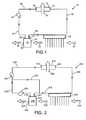
- FIG. 2is a schematic flow diagram of a cooling system according to another embodiment of the invention.
- FIG. 3is a schematic flow diagram of a cooling system according to another embodiment of the invention.
- FIG. 4is a schematic flow diagram of a cooling system according to another embodiment of the invention.
- FIG. 5is a schematic flow diagram of a cooling system according to another embodiment of the invention.
- FIG. 6is a schematic flow diagram of a cooling system according to another embodiment of the invention.
- FIG. 7is a schematic flow diagram of a cooling system according to another embodiment of the invention.
- FIG. 8is a schematic flow diagram of a cooling system according to another embodiment of the invention.
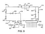
- FIG. 9is a schematic flow diagram of a cooling system according to another embodiment of the invention.
- FIGS. 1-9each show the cooling component of an air handling system of a heating, ventilating, and air conditioning (HVAC) system or climate control system (not shown) for a vehicle (not shown) according to an embodiment of the invention.
- HVACheating, ventilating, and air conditioning
- the cooling componentis also commonly referred to as a HVAC air handling system in the art.
- the HVAC systemtypically provides heating, ventilation, and air conditioning for a passenger compartment (not shown) of the vehicle.
- the HVAC system, including the cooling componentis adapted to be installed in the engine compartment (not shown) or other available space (not shown) of the vehicle.
- the HVAC systemcommunicates with the passenger compartment and ambient air through ducting or other conduit systems.
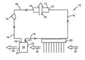
- FIG. 1shows a cooling system 10 that includes a first heat exchanger 12 , a first means for regulating flow 14 of a first fluid (not shown) in a conduit 16 , a second heat exchanger 18 , and a thermoelectric device 20 .
- the first heat exchanger 12includes a cold side (not shown) with a first inlet 13 and a first outlet 15 , and a hot side (not shown).
- the cold sideis in fluid communication with the first fluid.
- the first inlet 13is in fluid communication with the conduit 16 which is in fluid communication with the thermoelectric device 20 .
- the first outlet 15is in fluid communication with the conduit 16 which is in fluid communication with the first means for regulating flow 14 .
- the hot sideis in fluid communication with an ambient air stream 24 .
- the first heat exchanger 12is a low-temperature core. It is understood that any conventional heat exchanger may be used such as a shell and tube heat exchanger, a plate heat exchanger, an air-cooled heat exchanger, or other cooling device known in the art.
- the first fluidis a liquid having a mix of water and glycol. It is understood that the first fluid may also be water or any other liquid, gas, coolant, or multipurpose solid-liquid convection medium as desired.
- the first means for regulating flow 14is a pump disposed between the first heat exchanger 12 and the second heat exchanger 18 .
- the first means for regulating flow 14may be any pump, such as a positive displacement pump, centrifugal pump, electrostatic pump, or any other pump known in the art. It is understood that the first means for regulating flow 14 may be any fluid controlling device such as a valve, for example.
- the first means for regulating flow 14can be located anywhere on the cooling system 10 , as desired.
- the second heat exchanger 18includes a cold side (not shown) with a second inlet 19 and a second outlet 21 , and a hot side (not shown) with a third inlet 23 and a third outlet 25 .
- the cold sideis in fluid communication with the first fluid.
- the second inlet 19is in fluid communication with the conduit 16 which is in fluid communication with the first means for regulating flow 14 .
- the second outlet 21is in fluid communication with the conduit 16 which is in fluid communication with the thermoelectric device 20 .
- the hot sideis in fluid communication with a second fluid 22 .
- the second fluid 22flows through the cooling system 10 in HVAC ducting (not shown) or other conduit systems known in the art.
- the third inlet 23is in fluid communication with the HVAC ducting which is in fluid communication with the thermoelectric device 20 .
- the third outlet 25in fluid communication with the HVAC ducting which is in fluid communication with the passenger cabin (not shown).
- the second heat exchanger 18is a heater core.
- the heater coremay be a water-to-air heat exchanger used to provide the heated second fluid 22 to the passenger cabin. Any conventional heat exchanger may be used such as a shell and tube heat exchanger, a plate heat exchanger, an air-cooled heat exchanger, or other heating device known in the art.
- the second fluid 22is air.
- the second fluid 22may be ambient air from outside the passenger cabin or re-circulated air from inside the passenger cabin. It is understood that other fluids can be used such as a liquid, a gas, a coolant, or a multipurpose solid-liquid convection medium, for example.
- thermoelectric device 20is in fluid communication with the conduit 16 that is in fluid communication with the first heat exchanger 12 and the second heat exchanger 18 .
- the thermoelectric device 20is also in fluid communication with the second fluid 22 .
- the thermoelectric device 20may be any conventional device such as the thermoelectric systems described in U.S. Pat. No. 6,539,725 to Bell; quantum tunneling converters; a Peltier device; thermoionic modules; magneto caloric modules; acoustic heating mechanisms; other solid state heat pumping devices; or any combination of the devices listed above. Although a single thermoelectric device 20 is shown, it is understood that additional thermoelectric devices can be used, as desired.
- the first heat exchanger 12is adapted to cool the first fluid using an ambient air stream 24 .
- the first fluidenters a cold side of the first heat exchanger 12 through the conduit 16 at the inlet 13 .
- the ambient air stream 24enters a hot side of the first heat exchanger 12 from outside the vehicle.
- the ambient air stream 24passes through the hot side of the first heat exchanger 12 , thereby cooling the first fluid passing through the cold side of the first heat exchanger 12 .
- the cooled first fluidexits the first heat exchanger 12 through the conduit 16 at an outlet 15 as the ambient air stream 24 exits the hot side of the first heat exchanger 12 and exits the cooling system 10 .
- the ambient air stream 24is the temperature of the ambient air, such as 120 degrees Fahrenheit on a hot day. It is understood that alternative fluids may be used to cool the first fluid in the first exchanger 12 .
- the first means for regulating flow 14circulates the first fluid through the conduit 16 of the cooling system 10 .
- the first means for regulating flow 14causes the first fluid to flow through the first heat exchanger 12 , the second heat exchanger 18 , and the thermoelectric device 20 .
- the second heat exchanger 18heats a second fluid 22 and cools the first fluid. However, it is understood that in the broadest sense, the second heat exchanger 18 conditions the second fluid 22 . Conditioned as used herein means heating, cooling, maintaining a desired temperature, and the like. Thus, although the descriptions herein are limited to heating the second fluid 22 , the invention is not so limited.
- the first fluidAfter exiting the first heat exchanger 12 , the first fluid is caused to flow through the conduit 16 and enter a cold side of the second heat exchanger 18 at a second inlet 19 .
- the second fluid 22enters a hot side of the second heat exchanger 18 through a third inlet 23 at a temperature less than a desired temperature.
- the second fluid 22is heated to the desired temperature by the first fluid.
- the first fluidthen exits the second heat exchanger 18 through the conduit 16 at the second outlet 21 and is caused to flow to the thermoelectric device 20 by the first means for regulating flow 14 .
- the second fluid 22exits the second heat exchanger 18 at a third outlet 25 and flows into the passenger cabin of the vehicle.
- a passenger in the passenger cabincontrols the temperature of the second fluid 22 by setting the desired temperature using passenger cabin controls (not shown).
- the thermoelectric device 20in fluid communication with the first heat exchanger 12 and the second heat exchanger 18 , heats the first fluid and cools the second fluid 22 .
- the first means for regulating flow 14causes the first fluid to flow through the conduit 16 to communicate with the thermoelectric device 20 .
- the first fluidis heated by the thermoelectric device 20 before flowing through the conduit 16 back to the first heat exchanger 12 .
- the second fluid 22enters the thermoelectric device 20 at an entrance temperature.
- the second fluid 22is cooled by the thermoelectric device 20 , exits the thermoelectric device 20 at the temperature less than the desired temperature, and flows to the second heat exchanger 18 .
- the temperatureis taken to a temperature lower than the desired temperature to aid in the demisting of the second fluid 22 .
- the second fluid 22may be heated, cooled, dehumidified, demisted, or otherwise pretreated prior to communicating with the thermoelectric device 20 .
- the cooling efficiency of the thermoelectric device 20is affected by a temperature difference or delta-T between the first fluid and the second fluid 22 communicating with the thermoelectric device 20 . Because the first fluid entering the second heat exchanger 18 is at a temperature higher than the entrance temperature of the second fluid 22 , cooling the first fluid with the second heat exchanger 18 prior to the second fluid 22 entering the thermoelectric device 20 reduces the temperature difference or delta-T between the hot side and cold side of the thermoelectric device 20 .
- the coefficient of performance of the thermoelectric device 20changes in a non-linear fashion.
- the coefficient of performance (COP)is defined as the ratio of the rate of heat withdrawal from a cold side to the power required to withdraw the same heat.
- COP
- FIG. 2shows a cooling system 210 that includes a first heat exchanger 212 , a first means for regulating flow 214 of a first fluid (not shown) in a conduit 216 , a bypass conduit 232 , a second means for regulating flow 234 of the first fluid, a second heat exchanger 218 , and a thermoelectric device 220 .
- the first heat exchanger 212includes a cold side (not shown) with a first inlet 213 and a first outlet 215 , and a hot side (not shown).
- the cold sideis in fluid communication with the first fluid.
- the first inlet 213is in fluid communication with the conduit 216 which is in fluid communication with the thermoelectric device 220 .
- the first outlet 215is in fluid communication with the conduit 216 which is in fluid communication with the first means for regulating flow 214 .
- the hot sideis in fluid communication with an ambient air stream 224 .
- the first heat exchanger 212is a low-temperature core.
- the first fluidis a liquid having a mix of water and glycol. It is understood that the first fluid may also be water or any other liquid, gas, coolant, or multipurpose solid-liquid convection medium as desired.
- the first means for regulating flow 214is a pump disposed between the first heat exchanger 212 and the second heat exchanger 218 .
- the first means for regulating flow 214may be any pump, such as a positive displacement pump, centrifugal pump, electrostatic pump, or any other pump known in the art. It is understood that the first means for regulating flow 214 may be any fluid controlling device such as a valve, for example.
- the first means for regulating flow 214can be located anywhere on the cooling system 210 , as desired.
- bypass conduit 232is disposed between the first means for regulating flow 214 and the thermoelectric device 220 and bypasses the second heat exchanger 218 .
- the second means for regulating flow 234is a valve disposed between the first means for regulating flow 214 and the second heat exchanger 218 .
- the second means for regulating flow 234may be any pump, such as a positive displacement pump, centrifugal pump, electrostatic pump, or any other pump known in the art. It is understood that the second means for regulating flow 234 may be any fluid controlling device such as a valve, for example.
- the second means for regulating flow 234can be located either on the bypass conduit 232 or disposed between the first means for regulating flow 214 and the second heat exchanger 218 , as desired.
- the second heat exchanger 218includes a cold side (not shown) with a second inlet 219 and a second outlet 221 , and a hot side (not shown) with a third inlet 223 and a third outlet 225 .
- the cold sideis in fluid communication with the first fluid.
- the second inlet 219is in fluid communication with the conduit 216 which is in fluid communication with the first means for regulating flow 214 .
- the second outlet 221is in fluid communication with the conduit 216 which is in fluid communication with the thermoelectric device 220 .
- the hot sideis in fluid communication with a second fluid 222 .
- the second fluid 222flows through the cooling system 210 in HVAC ducting (not shown) or other conduit systems known in the art.
- the third inlet 223is in fluid communication with the HVAC ducting which is in fluid communication with the thermoelectric device 220 .
- the third outlet 225in fluid communication with the HVAC ducting which is in fluid communication with the passenger cabin.
- the second heat exchanger 218is a heater core.
- the heater coremay be a water-to-air heat exchanger used to provide the heated second fluid 222 to the passenger cabin. Any conventional heat exchanger may be used such as a shell and tube heat exchanger, a plate heat exchanger, an air-cooled heat exchanger, or other heating device known in the art.
- the second fluid 222is air.
- the second fluid 222may be ambient air from outside the passenger cabin or re-circulated air from inside the passenger cabin. It is understood that other fluids can be used such as a liquid, a gas, a coolant, or a multipurpose solid-liquid convection medium, for example.
- the thermoelectric device 220is in fluid communication with the conduit 216 that is in fluid communication with the first heat exchanger 212 and the second heat exchanger 218 .
- the thermoelectric device 220is also in fluid communication with the second fluid 222 .
- the thermoelectric device 220may be any conventional device such as the thermoelectric systems described in U.S. Pat. No. 6,539,725 to Bell; quantum tunneling converters; a Peltier device; thermoionic modules; magneto caloric modules; acoustic heating mechanisms; other solid state heat pumping devices; or any combination of the devices listed above.
- a single thermoelectric device 220is shown, it is understood that additional thermoelectric devices can be used, as desired.
- a single thermoelectric device 220is shown, it is understood that additional thermoelectric devices can be used, as desired.
- the first heat exchanger 212is adapted to cool the first fluid using an ambient air stream 224 .
- the first fluidenters a cold side of the first heat exchanger 212 through the conduit 216 at the inlet 213 .
- the ambient air stream 224enters a hot side of the first heat exchanger 212 from outside the vehicle.
- the ambient air stream 224passes through the hot side of the first heat exchanger 212 , thereby cooling the first fluid passing through the cold side of the first heat exchanger 212 .
- the cooled first fluidexits the first heat exchanger 212 through the conduit 216 at an outlet 215 as the ambient air stream 224 exits the hot side of the first heat exchanger 212 and exits the cooling system 210 .
- the ambient air stream 224is the temperature of the ambient air, such as 120 degrees Fahrenheit on a hot day. It is understood that alternative fluids may be used to cool the first fluid in the first exchanger 212 .
- the first means for regulating flow 214circulates the first fluid through the conduit 216 of the cooling system 210 .
- the first means for regulating flow 214causes the first fluid to flow through the first heat exchanger 212 , the second heat exchanger 218 , and the thermoelectric device 220 .
- the second means for regulating flow 234facilitates the flow of the first fluid in the conduit 216 through the conduit 216 to the second heat exchanger 218 and causes at least a portion of the first fluid in the conduit 216 to flow through the bypass conduit 232 .
- a portion of the first fluidis caused to bypass the second heat exchanger 218 .
- the portion of the first fluid that bypasses the second heat exchanger 218is caused to flow to the thermoelectric device 220 after rejoining the conduit 216 .
- the second heat exchanger 218heats a second fluid 222 and cools the first fluid. After exiting the first heat exchanger 212 , the first fluid is caused to flow through the conduit 216 and enter a cold side of the second heat exchanger 218 at a second inlet 219 .
- the second fluid 222enters a hot side of the second heat exchanger 218 through a third inlet 223 at a temperature less than a desired temperature.
- the second fluid 222is heated to the desired temperature by the first fluid.
- the first fluidthen exits the second heat exchanger 218 through the conduit 216 at the second outlet 221 and is caused to flow to the thermoelectric device 220 by the first means for regulating flow 214 .
- the second fluid 222exits the second heat exchanger 218 at a third outlet 225 and flows into the passenger cabin of the vehicle.
- a passenger in the passenger cabincontrols the temperature of the second fluid 222 by setting the desired temperature using passenger cabin controls (not shown).
- a portion of the first fluidis caused to flow through the bypass conduit 232 by the second means for regulating flow 234 .
- the remaining portion of the first fluidis caused to flow through the conduit 216 to the second heat exchanger 218 .
- the amount of the first fluid flowing to the second heat exchanger 218is altered.
- the temperature of the second fluid 222 exiting the second heat exchanger 218is also altered.
- the amount the temperature of the second fluid 222 is altereddepends on the amount of the first fluid bypassing the second heat exchanger 218 through the bypass conduit 232 .
- the amount of the first fluid flowing through the bypass conduit 232will vary based on the desired temperature set by the passenger for the second fluid 222 .
- the cooling system 210will dynamically regulate the flow of the first fluid through the bypass conduit 232 to balance the temperatures of the first fluid and the second fluid 222 throughout the cooling system 210 . It is understood that all of the first fluid may flow through either the conduit 216 or the bypass conduit 232 , or the first fluid can flow through both the conduit 216 and the bypass conduit 232 , depending on the desired temperature setting.
- the thermoelectric device 220in fluid communication with the first heat exchanger 212 and the second heat exchanger 218 , heats the first fluid and cools the second fluid 222 .
- the first means for regulating flow 214causes the first fluid to flow through the conduit 216 to communicate with the thermoelectric device 220 .
- the first fluidis heated by the thermoelectric device 220 before flowing through the conduit 216 back to the first heat exchanger 212 .
- the second fluid 222enters the thermoelectric device 220 at an entrance temperature.
- the second fluid 222is cooled by the thermoelectric device 220 , exits the thermoelectric device 220 at the temperature less than the desired temperature, and flows to the second heat exchanger 218 .
- the temperatureis taken to a temperature lower than the desired temperature to aid in the demisting of the second fluid 222 .
- the second fluid 222may be heated, cooled, dehumidified, demisted, or otherwise pretreated prior to communicating with the thermoelectric device 220 .
- FIG. 3shows a cooling system 310 according to another embodiment of the invention.
- the embodiment of FIG. 3is similar to the cooling system of FIG. 2 except as described below.
- FIG. 3includes reference numerals in the 300 s instead of the 200 s, with the remaining two digits the same.
- the second means for regulating flow 334is a pump disposed between the first means for regulating flow 314 and the thermoelectric device 320 on the bypass conduit 332 . It is understood that the second means for regulating flow 334 can be any conventional flow device such as a valve, for example.
- flow of the first fluid through the bypass conduit 332is regulated by the second means for regulating flow 334 .
- the remaining portion of the first fluidis caused to flow through the conduit 316 to the second heat exchanger 318 .
- the amount of the first fluid flowing to the second heat exchanger 318is altered.
- the temperature of the second fluid 322 exiting the second heat exchanger 318is also altered.
- the amount the temperature of the second fluid 322 is altereddepends on the amount of the first fluid bypassing the second heat exchanger 318 through the bypass conduit 332 .
- the amount of the first fluid flowing through the bypass conduit 332will vary based on the desired temperature set by the passenger for the second fluid 322 .
- the cooling system 310will dynamically regulate the flow of the first fluid through the bypass conduit 332 to balance the temperatures of the first fluid and the second fluid 322 throughout the cooling system 310 . It is understood that all of the first fluid may flow through either the conduit 316 or the bypass conduit 332 , or the first fluid can flow through both the conduit 316 and the bypass conduit 332 , depending on the desired temperature setting.
- FIG. 4shows a cooling system 410 according to another embodiment of the invention.
- the embodiment of FIG. 4is similar to the cooling system of FIG. 2 except as described below.
- FIG. 4includes reference numerals in the 400 s instead of the 200 s, with the remaining two digits the same.
- the second means for regulating flow 434is a valve disposed between the first means for regulating flow 414 and the second heat exchanger 418 .
- the second means for regulating flow 434may be any valve, such as a gate valve, a globe valve, a ball valve, a plug valve, a butterfly valve, or any other valve known in the art.
- a control systemnot shown
- flow of the first fluid through the bypass conduit 432is regulated by the second means for regulating flow 434 .
- a portion of the first fluidis caused to flow through the conduit 416 to the second heat exchanger 418 .
- the amount of the first fluid flowing to the second heat exchanger 418is altered.
- the temperature of the second fluid 422 exiting the second heat exchanger 418is also altered.
- the amount the temperature of the second fluid 422 is altereddepends on the amount of the first fluid bypassing the second heat exchanger 418 through the bypass conduit 432 .
- the amount of the first fluid flowing through the bypass conduit 432will vary based on the desired temperature set by the passenger for the second fluid 422 .
- the cooling system 410will dynamically regulate the flow of the first fluid through the bypass conduit 432 to balance the temperatures of the first fluid and the second fluid 422 throughout the cooling system 410 . It is understood that all of the first fluid may flow through either the conduit 416 or the bypass conduit 432 , or the first fluid can flow through both the conduit 416 and the bypass conduit 432 , depending on the desired temperature setting.
- FIG. 5shows a cooling system 510 that includes a first heat exchanger 512 , a first means for regulating flow 514 of a first fluid (not shown) in a conduit 516 , a bypass conduit 532 , a second means for regulating flow 534 of the first fluid in the conduit 516 , a third means for regulating flow 538 of the first fluid in the bypass conduit 532 , a second heat exchanger 518 , and a thermoelectric device 520 .
- the first heat exchanger 512includes a cold side (not shown) with a first inlet 513 and a first outlet 515 , and a hot side (not shown).
- the cold sideis in fluid communication with the first fluid.
- the first inlet 513is in fluid communication with the conduit 516 which is in fluid communication with the thermoelectric device 520 .
- the first outlet 515is in fluid communication with the conduit 516 which is in fluid communication with the first means for regulating flow 514 .
- the hot sideis in fluid communication with an ambient air stream 524 .
- the first heat exchanger 512is a low-temperature core.
- the first fluidis a liquid having a mix of water and glycol. It is understood that the first fluid may also be water or any other liquid, gas, coolant, or multipurpose solid-liquid convection medium as desired.
- the first means for regulating flow 514is a pump disposed between the first heat exchanger 512 and the second heat exchanger 518 .
- the first means for regulating flow 514may be any pump, such as a positive displacement pump, centrifugal pump, electrostatic pump, or any other pump known in the art. It is understood that the first means for regulating flow 514 may be any fluid controlling device such as a valve, for example.
- the first means for regulating flow 514can be located anywhere on the cooling system 510 , as desired.
- bypass conduit 532is disposed between the first means for regulating flow 514 and the thermoelectric device 520 and bypasses the second heat exchanger 518 .
- the second means for regulating flow 534is a valve disposed between the first means for regulating flow 514 and the second heat exchanger 518 .
- the second means for regulating flow 534may be any valve, such as a gate valve, a globe valve, a ball valve, a plug valve, a butterfly valve, or any other valve known in the art. It is understood that the second means for regulating flow 534 may be any fluid controlling device such as a pump, for example.
- the third means for regulating flow 538is a valve disposed between the first means for regulating flow 514 and the thermoelectric device 520 on the bypass conduit 532 .
- the third means for regulating flow 538may be any valve, such as a gate valve, a globe valve, a ball valve, a plug valve, a butterfly valve, or any other valve known in the art. It is understood that the third means for regulating flow 538 may be any fluid controlling device such as a pump, for example.
- the second heat exchanger 518includes a cold side (not shown) with a second inlet 519 and a second outlet 521 , and a hot side (not shown) with a third inlet 523 and a third outlet 525 .
- the cold sideis in fluid communication with the first fluid.
- the second inlet 519is in fluid communication with the conduit 516 which is in fluid communication with the first means for regulating flow 514 .
- the second outlet 521is in fluid communication with the conduit 516 which is in fluid communication with the thermoelectric device 520 .
- the hot sideis in fluid communication with a second fluid 522 .
- the second fluid 522flows through the cooling system 510 in HVAC ducting (not shown) or other conduit systems known in the art.
- the third inlet 523is in fluid communication with the HVAC ducting which is in fluid communication with the thermoelectric device 520 .
- the third outlet 525in fluid communication with the HVAC ducting which is in fluid communication with the passenger cabin.
- the second heat exchanger 518is a heater core.
- the heater coremay be a water-to-air heat exchanger used to provide the heated second fluid 522 to the passenger cabin. Any conventional heat exchanger may be used such as a shell and tube heat exchanger, a plate heat exchanger, an air-cooled heat exchanger, or other heating device known in the art.
- the second fluid 522is air.
- the second fluid 522may be ambient air from outside the passenger cabin or re-circulated air from inside the passenger cabin. It is understood that other fluids can be used such as a liquid, a gas, a coolant, or a multipurpose solid-liquid convection medium, for example.
- the thermoelectric device 520is in fluid communication with the conduit 516 that is in fluid communication with the first heat exchanger 512 and the second heat exchanger 518 .
- the thermoelectric device 520is also in fluid communication with the second fluid 522 .
- the thermoelectric device 520may be any conventional device such as the thermoelectric systems described in U.S. Pat. No. 6,539,725 to Bell; quantum tunneling converters; a Peltier device; thermoionic modules; magneto caloric modules; acoustic heating mechanisms; other solid state heat pumping devices; or any combination of the devices listed above.
- thermoelectric device 520Although a single thermoelectric device 520 is shown, it is understood that additional thermoelectric devices can be used, as desired. Although a single thermoelectric device 520 is shown, it is understood that additional thermoelectric devices can be used, as desired. Although a single thermoelectric device 520 is shown, it is understood that additional thermoelectric devices can be used, as desired.
- the first heat exchanger 512is adapted to cool the first fluid using an ambient air stream 524 .
- the first fluidenters a cold side of the first heat exchanger 512 through the conduit 516 at the inlet 513 .
- the ambient air stream 524enters a hot side of the first heat exchanger 512 from outside the vehicle.
- the ambient air stream 524passes through the hot side of the first heat exchanger 512 , thereby cooling the first fluid passing through the cold side of the first heat exchanger 512 .
- the cooled first fluidexits the first heat exchanger 512 through the conduit 516 at an outlet 515 as the ambient air stream 524 exits the hot side of the first heat exchanger 512 and exits the cooling system 510 .
- the ambient air stream 524is the temperature of the ambient air, such as 120 degrees Fahrenheit on a hot day. It is understood that alternative fluids may be used to cool the first fluid in the first exchanger 512 .
- the first means for regulating flow 514circulates the first fluid through the conduit 516 of the cooling system 510 .
- the first means for regulating flow 514causes the first fluid to flow through the first heat exchanger 512 , the second heat exchanger 518 , and the thermoelectric device 520 .
- the second means for regulating flow 534facilitates the flow of at least a portion of the first fluid in the conduit 516 through the conduit 516 to the second heat exchanger 518 .
- the third means for regulating flow 538facilitates the flow of the first fluid not flowing to the second heat exchanger 518 through the bypass conduit 532 , thereby bypassing the second heat exchanger 518 .
- the portion of the first fluid that bypasses the second heat exchanger 518is caused to flow to the thermoelectric device 520 after rejoining the conduit 516 . It is understood that it may be desirable that the first fluid is not permitted to flow through the bypass conduit 532 .
- the valvesmay be controlled by actuators (not shown) connected to a control system (not shown) to control the amount of flow of the first fluid therethrough.
- the second heat exchanger 518heats a second fluid 522 and cools the first fluid. After exiting the first heat exchanger 512 , the first fluid is caused to flow through the conduit 516 and enter a cold side of the second heat exchanger 518 at a second inlet 519 . The second fluid 522 enters a hot side of the second heat exchanger 518 through a third inlet 523 at a temperature less than a desired temperature. Within the second heat exchanger 518 , the second fluid 522 is heated to the desired temperature by the first fluid. The first fluid exits the second heat exchanger 518 through the conduit 516 at the second outlet 521 and is caused to flow to the thermoelectric device 520 . The second fluid 522 exits the second heat exchanger 518 at a third outlet 525 and flows into the passenger cabin of the vehicle. A passenger in the passenger cabin controls the temperature of the second fluid 522 by setting the desired temperature using passenger cabin controls (not shown).
- flow of the first fluid through the bypass conduit 532is regulated by the third means for regulating flow 538 .
- a portion of the first fluidis caused to flow through the bypass conduit 532 to bypass the second heat exchanger 518 by the third means for regulating flow 538 .
- the amount of the first fluid flowing to the second heat exchanger 518is altered.
- the temperature of the second fluid 522 exiting the second heat exchanger 518is also altered.
- the amount the temperature of the second fluid 522 is altereddepends on the amount of the first fluid bypassing the second heat exchanger 518 through the bypass conduit 532 .
- the amount of the first fluid flowing through the bypass conduit 532will vary based on the desired temperature set by the passenger for the second fluid 522 .
- the cooling system 510will dynamically regulate the flow of the first fluid through the bypass conduit 532 to balance the temperatures of the first fluid and the second fluid 522 throughout the cooling system 510 . It is understood that all of the first fluid may flow through either the conduit 516 or the bypass conduit 532 , or the first fluid can flow through both the conduit 516 and the bypass conduit 532 , depending on the desired temperature setting.
- the thermoelectric device 520in fluid communication with the first heat exchanger 512 and the second heat exchanger 518 , heats the first fluid and cools the second fluid 522 .
- the first means for regulating flow 514causes the first fluid to flow through the conduit 516 to communicate with the thermoelectric device 520 .
- the first fluidis heated by the thermoelectric device 520 before flowing through the conduit 516 back to the first heat exchanger 512 .
- the second fluid 522enters the thermoelectric device 520 at an entrance temperature.
- the second fluid 522is cooled by the thermoelectric device 520 , exits the thermoelectric device 520 at the temperature less than the desired temperature, and flows to the second heat exchanger 518 .
- the temperatureis taken to a temperature lower than the desired temperature to aid in the demisting of the second fluid 522 .
- the second fluid 522may be heated, cooled, dehumidified, demisted, or otherwise pretreated prior to communicating with the thermoelectric device 520 .
- FIG. 6shows a cooling system 610 that includes a first heat exchanger 612 , a first means for regulating flow 614 of a first fluid (not shown) in a conduit 616 , a second heat exchanger 618 , a thermoelectric device 620 , a thermoelectric device bypass 642 , and a second means for regulating flow 634 of the first fluid in the thermoelectric device bypass 642 .
- the first heat exchanger 612includes a cold side (not shown) with a first inlet 613 and a first outlet 615 , and a hot side (not shown).
- the cold sideis in fluid communication with the first fluid.
- the first inlet 613is in fluid communication with the conduit 616 which is in fluid communication with the thermoelectric device bypass 642 and the thermoelectric device 620 .
- the first outlet 615is in fluid communication with the conduit 616 which is in fluid communication with the first means for regulating flow 614 .
- the hot sideis in fluid communication with an ambient air stream 624 .
- the first heat exchanger 612is a low-temperature core.
- the first fluidis a liquid having a mix of water and glycol. It is understood that the first fluid may also be water or any other liquid, gas, coolant, or multipurpose solid-liquid convection medium as desired.
- the first means for regulating flow 614is a pump disposed between the first heat exchanger 612 and the second heat exchanger 618 .
- the first means for regulating flow 614may be any pump, such as a positive displacement pump, centrifugal pump, electrostatic pump, or any other pump known in the art. It is understood that the first means for regulating flow 614 may be any fluid controlling device such as a valve, for example.
- the first means for regulating flow 614can be located anywhere on the cooling system 610 , as desired.
- the second heat exchanger 618includes a cold side (not shown) with a second inlet 619 and a second outlet 621 , and a hot side (not shown) with a third inlet 623 and a third outlet 625 .
- the cold sideis in fluid communication with the first fluid.
- the second inlet 619is in fluid communication with the conduit 616 which is in fluid communication with the first means for regulating flow 614 .
- the second outlet 621is in fluid communication with the conduit 616 which is in fluid communication with the thermoelectric device 620 .
- the hot sideis in fluid communication with a second fluid 622 .
- the second fluid 622flows through the cooling system 610 in HVAC ducting (not shown) or other conduit systems known in the art.
- the third inlet 623is in fluid communication with the HVAC ducting which is in fluid communication with the thermoelectric device 620 .
- the third outlet 625in fluid communication with the HVAC ducting which is in fluid communication with the passenger cabin.
- the second heat exchanger 618is a heater core.
- the heater coremay be a water-to-air heat exchanger used to provide the heated second fluid 622 to the passenger cabin. Any conventional heat exchanger may be used such as a shell and tube heat exchanger, a plate heat exchanger, an air-cooled heat exchanger, or other heating device known in the art.
- the second fluid 622is air.
- the second fluid 622may be ambient air from outside the passenger cabin or re-circulated air from inside the passenger cabin. It is understood that other fluids can be used such as a liquid, a gas, a coolant, or a multipurpose solid-liquid convection medium, for example.
- the thermoelectric device 620is in fluid communication with the conduit 616 that is in fluid communication with the first heat exchanger 612 and the second heat exchanger 618 .
- the thermoelectric device 620is also in fluid communication with the second fluid 622 .
- the thermoelectric device 620may be any conventional device such as the thermoelectric systems described in U.S. Pat. No. 6,539,725 to Bell; quantum tunneling converters; a Peltier device; thermoionic modules; magneto caloric modules; acoustic heating mechanisms; other solid state heat pumping devices; or any combination of the devices listed above.
- a single thermoelectric device 620is shown, it is understood that additional thermoelectric devices can be used, as desired.
- a single thermoelectric device 620is shown, it is understood that additional thermoelectric devices can be used, as desired.
- thermoelectric device bypass 642is disposed between the first heat exchanger 612 and the thermoelectric device 620 at a point 644 along the thermoelectric device 620 to provide a fluid conduit that bypasses a portion of the thermoelectric device 620 .
- the second means for regulating flow 634is a valve disposed between the thermoelectric device 620 and the first heat exchanger 612 on the thermoelectric device bypass 642 .
- the second means for regulating flow 634may be any valve, such as a gate valve, a globe valve, a ball valve, a plug valve, a butterfly valve, or any other valve known in the art. It is understood that the second means for regulating flow 634 may be any fluid controlling device such as a pump, for example.
- the first heat exchanger 612is adapted to cool the first fluid using an ambient air stream 624 .
- the first fluidenters a cold side of the first heat exchanger 612 through the conduit 616 at the inlet 613 .
- the ambient air stream 624enters a hot side of the first heat exchanger 612 from outside the vehicle.
- the ambient air stream 624passes through the hot side of the first heat exchanger 612 , thereby cooling the first fluid passing through the cold side of the first heat exchanger 612 .
- the cooled first fluidexits the first heat exchanger 612 through the conduit 616 at an outlet 615 as the ambient air stream 624 exits the hot side of the first heat exchanger 612 and exits the cooling system 610 .
- the ambient air stream 624is the temperature of the ambient air, such as 120 degrees Fahrenheit on a hot day. It is understood that alternative fluids may be used to cool the first fluid in the first exchanger 612 .
- the first means for regulating flow 614circulates the first fluid through the conduit 616 of the cooling system 610 .
- the first means for regulating flow 614causes the first fluid to flow through the first heat exchanger 612 , the second heat exchanger 618 , and the thermoelectric device 620 .
- the second heat exchanger 618heats a second fluid 622 and cools the first fluid. After exiting the first heat exchanger 612 , the first fluid is caused to flow through the conduit 616 and enter a cold side of the second heat exchanger 618 at a second inlet 619 . The second fluid 622 enters a hot side of the second heat exchanger 618 through a third inlet 623 at a temperature less than a desired temperature. Within the second heat exchanger 618 , the second fluid 622 is heated to the desired temperature by the first fluid. The first fluid exits the second heat exchanger 618 through the conduit 616 at the second outlet 621 and is caused to flow to the thermoelectric device 620 . The second fluid 622 exits the second heat exchanger 618 at a third outlet 625 and flows into the passenger cabin of the vehicle. A passenger in the passenger cabin controls the temperature of the second fluid 622 by setting the desired temperature using passenger cabin controls (not shown).
- the thermoelectric device 620in fluid communication with the first heat exchanger 612 and the second heat exchanger 618 , heats the first fluid and cools the second fluid 622 .
- the first means for regulating flow 614causes the first fluid to flow through the conduit 616 to communicate with the thermoelectric device 620 .
- the first fluidis heated by the thermoelectric device 620 before flowing through the conduit 616 back to the first heat exchanger 612 .
- the second means for regulating flow 634facilitates the flow of at least a portion 636 of the first fluid in the thermoelectric device 620 to flow through the thermoelectric device bypass 642 to bypass a portion of the thermoelectric device 620 at the point 644 along the thermoelectric device 620 .
- the portion of the first fluid that bypasses the portion of the thermoelectric device 620is caused to flow to the first heat exchanger 612 after rejoining the conduit 616 . It is understood that it may be desirable that the first fluid is not permitted to flow through the thermoelectric device bypass 642 . Typically it is desired for the valve to be controlled by actuators (not shown) connected to a control system (not shown) to control the amount of flow of the first fluid therethrough.
- the second fluid 622enters the thermoelectric device 620 at an entrance temperature.
- the second fluid 622is cooled by the thermoelectric device 620 , exits the thermoelectric device 620 at the temperature less than the desired temperature, and flows to the second heat exchanger 618 .
- the temperatureis taken to a temperature lower than the desired temperature to aid in the demisting of the second fluid 622 .
- the second fluid 622may be heated, cooled, dehumidified, demisted, or otherwise pretreated prior to communicating with the thermoelectric device 620 .
- thermoelectric device bypass 642flow of the first fluid through the thermoelectric device bypass 642 is regulated by the second means for regulating flow 634 .
- the amount of the first fluid flowing through the entire thermoelectric device 620is altered.
- the temperature of the first fluid entering the second heat exchanger 618is altered, thereby altering the temperature of the second fluid 622 exiting the second heat exchanger 618 .
- the amount the temperature of the second fluid 622 is altereddepends on the amount of the first fluid bypassing the thermoelectric device 620 through the thermoelectric device bypass 642 .
- the amount of the first fluid flowing through the thermoelectric device bypass 642will vary based on the desired temperature set by the passenger for the second fluid 622 .
- the cooling system 610will dynamically regulate the flow of the first fluid through the thermoelectric device bypass 642 to balance the temperatures of the first fluid and the second fluid 622 throughout the cooling system 610 . It is understood that all of the first fluid may flow through either the conduit 616 or the thermoelectric device bypass 642 , or the first fluid can flow through both the conduit 616 and the thermoelectric device bypass 642 , depending on the desired temperature setting.
- FIG. 7shows a cooling system 710 that includes a first heat exchanger 712 , a first means for regulating flow 714 of a first fluid (not shown) in a conduit 716 , a bypass conduit 732 , a second means for regulating flow 734 of the first fluid in the conduit 716 , a second heat exchanger 718 , a thermoelectric device 720 , a thermoelectric device bypass 742 , and a third means for regulating flow 738 of the first fluid in the thermoelectric device bypass 742 .
- the first heat exchanger 712includes a cold side (not shown) with a first inlet 713 and a first outlet 715 , and a hot side (not shown).
- the cold sideis in fluid communication with the first fluid.
- the first inlet 713is in fluid communication with the conduit 716 which is in fluid communication with the thermoelectric device 642 and the thermoelectric device 720 .
- the first outlet 715is in fluid communication with the conduit 716 which is in fluid communication with the first means for regulating flow 714 .
- the hot sideis in fluid communication with an ambient air stream 724 .
- the first heat exchanger 712is a low-temperature core.
- the first fluidis a liquid having a mix of water and glycol. It is understood that the first fluid may also be water or any other liquid, gas, coolant, or multipurpose solid-liquid convection medium as desired.
- the first means for regulating flow 714is a pump disposed between the first heat exchanger 712 and the second heat exchanger 718 .
- the first means for regulating flow 714may be any pump, such as a positive displacement pump, centrifugal pump, electrostatic pump, or any other pump known in the art. It is understood that the first means for regulating flow 714 may be any fluid controlling device such as a valve, for example.
- the first means for regulating flow 714can be located anywhere on the cooling system 710 , as desired.
- bypass conduit 732is disposed between the first means for regulating flow 714 and the thermoelectric device 720 and bypasses the second heat exchanger 718 .
- the second means for regulating flow 734is a valve disposed between the first means for regulating flow 714 and the second heat exchanger 718 .
- the second means for regulating flow 734may be any valve, such as a gate valve, a globe valve, a ball valve, a plug valve, a butterfly valve, or any other valve known in the art. It is understood that the second means for regulating flow 734 may be any fluid controlling device such as a pump, for example.
- the second heat exchanger 718includes a cold side (not shown) with a second inlet 719 and a second outlet 721 , and a hot side (not shown) with a third inlet 723 and a third outlet 725 .
- the cold sideis in fluid communication with the first fluid.
- the second inlet 719is in fluid communication with the conduit 716 which is in fluid communication with the first means for regulating flow 714 .
- the second outlet 721is in fluid communication with the conduit 716 which is in fluid communication with the thermoelectric device 720 .
- the hot sideis in fluid communication with a second fluid 722 .
- the second fluid 722flows through the cooling system 710 in HVAC ducting (not shown) or other conduit systems known in the art.
- the third inlet 723is in fluid communication with the HVAC ducting which is in fluid communication with the thermoelectric device 720 .
- the third outlet 725in fluid communication with the HVAC ducting which is in fluid communication with the passenger cabin.
- the second heat exchanger 718is a heater core.
- the heater coremay be a water-to-air heat exchanger used to provide the heated second fluid 722 to the passenger cabin. Any conventional heat exchanger may be used such as a shell and tube heat exchanger, a plate heat exchanger, an air-cooled heat exchanger, or other heating device known in the art.
- the second fluid 722is air.
- the second fluid 722may be ambient air from outside the passenger cabin or re-circulated air from inside the passenger cabin. It is understood that other fluids can be used such as a liquid, a gas, a coolant, or a multipurpose solid-liquid convection medium, for example.
- the thermoelectric device 720is in fluid communication with the conduit 716 that is in fluid communication with the first heat exchanger 712 and the second heat exchanger 718 .
- the thermoelectric device 720is also in fluid communication with the second fluid 722 .
- the thermoelectric device 720may be any conventional device such as the thermoelectric systems described in U.S. Pat. No. 6,539,725 to Bell; quantum tunneling converters; a Peltier device; thermoionic modules; magneto caloric modules; acoustic heating mechanisms; other solid state heat pumping devices; or any combination of the devices listed above.
- a single thermoelectric device 720is shown, it is understood that additional thermoelectric devices can be used, as desired.
- a single thermoelectric device 720is shown, it is understood that additional thermoelectric devices can be used, as desired.
- thermoelectric device bypass 742is disposed between the first heat exchanger 712 and the thermoelectric device 720 at a point 744 along the thermoelectric device 720 to provide a fluid conduit that bypasses a portion of the thermoelectric device 720 .
- the third means for regulating flow 738is a valve disposed between the thermoelectric device 720 and the first heat exchanger 712 on the thermoelectric device bypass 742 .
- the third means for regulating flow 738may be any valve, such as a gate valve, a globe valve, a ball valve, a plug valve, a butterfly valve, or any other valve known in the art. It is understood that the third means for regulating flow 738 may be any fluid controlling device such as a pump, for example.
- the first heat exchanger 712is adapted to cool the first fluid using an ambient air stream 724 .
- the first fluidenters a cold side of the first heat exchanger 712 through the conduit 716 at the inlet 713 .
- the ambient air stream 724enters a hot side of the first heat exchanger 712 from outside the vehicle.
- the ambient air stream 724passes through the hot side of the first heat exchanger 712 , thereby cooling the first fluid passing through the cold side of the first heat exchanger 712 .
- the cooled first fluidexits the first heat exchanger 712 through the conduit 716 at an outlet 715 as the ambient air stream 724 exits the hot side of the first heat exchanger 712 and exits the cooling system 710 .
- the ambient air stream 724is the temperature of the ambient air, such as 120 degrees Fahrenheit on a hot day. It is understood that alternative fluids may be used to cool the first fluid in the first exchanger 712 .
- the first means for regulating flow 714circulates the first fluid through the conduit 716 of the cooling system 710 .
- the first means for regulating flow 714causes the first fluid to flow through the first heat exchanger 712 , the second heat exchanger 718 , and the thermoelectric device 720 .
- the second means for regulating flow 734facilitates the flow of the first fluid in the conduit 716 through the conduit 716 to the second heat exchanger 718 and causes at least a portion of the first fluid in the conduit 716 to flow through the bypass conduit 732 .
- a portion of the first fluidis caused to bypass the second heat exchanger 718 .
- the portion of the first fluid that bypasses the second heat exchanger 718is caused to flow to the thermoelectric device 720 after rejoining the conduit 716 . It is understood that it may be desirable that the first fluid is not permitted to flow through the bypass conduit 732 .
- the valvemay be controlled by an actuator (not shown) connected to a control system (not shown) to control the amount of flow of the first fluid therethrough.
- the second heat exchanger 718heats a second fluid 722 and cools the first fluid. After exiting the first heat exchanger 712 , the first fluid is caused to flow through the conduit 716 and enter a cold side of the second heat exchanger 718 at a second inlet 719 . The second fluid 722 enters a hot side of the second heat exchanger 718 through a third inlet 723 at a temperature less than a desired temperature. Within the second heat exchanger 718 , the second fluid 722 is heated to the desired temperature by the first fluid. The first fluid exits the second heat exchanger 718 through the conduit 716 at the second outlet 721 and is caused to flow to the thermoelectric device 720 . The second fluid 722 exits the second heat exchanger 718 at a third outlet 725 and flows into the passenger cabin of the vehicle. A passenger in the passenger cabin controls the temperature of the second fluid 722 by setting the desired temperature using passenger cabin controls (not shown).
- the thermoelectric device 720in fluid communication with the first heat exchanger 712 and the second heat exchanger 718 , heats the first fluid and cools the second fluid 722 .
- the first means for regulating flow 714causes the first fluid to flow through the conduit 716 to communicate with the thermoelectric device 720 .
- the first fluidis heated by the thermoelectric device 720 before flowing through the conduit 716 back to the first heat exchanger 712 .
- the second means for regulating flow 734facilitates the flow of at least a portion 736 of the first fluid in the thermoelectric device 720 to flow through the thermoelectric device bypass 742 to bypass a portion of the thermoelectric device 720 at the desired point 744 along the thermoelectric device 720 .
- the portion of the first fluid that bypasses the portion of the thermoelectric device 720is caused to flow to the first heat exchanger 712 after rejoining the conduit 716 . It is understood that it may be desirable that the first fluid is not permitted to flow through the thermoelectric device bypass 742 . Typically it is desired for the valve to be controlled by actuators (not shown) connected to a control system (not shown) to control the amount of flow of the first fluid therethrough.
- the second fluid 722enters the thermoelectric device 720 at an entrance temperature.
- the second fluid 722is cooled by the thermoelectric device 720 , exits the thermoelectric device 720 at the temperature less than the desired temperature, and flows to the second heat exchanger 718 .
- the temperatureis taken to a temperature lower than the desired temperature to aid in the demisting of the second fluid 722 .
- the second fluid 722may be heated, cooled, dehumidified, demisted, or otherwise pretreated prior to communicating with the thermoelectric device 720 .
- flow of the first fluid through the bypass conduit 732is regulated by the second means for regulating flow 734
- the flow of the first fluid through the thermoelectric device bypass 742is regulated by the third means for regulating flow 738 .
- a portion of the first fluidis caused to flow through the bypass conduit 732 to the thermoelectric 720 by the second means for regulating flow 734 .
- the remaining portion of the first fluidis caused to flow through the conduit 716 to the second heat exchanger 718 .
- the bypass conduit 732By flowing through the bypass conduit 732 , the amount of the first fluid flowing to the second heat exchanger 718 , as well as the temperature of the first fluid flowing to the thermoelectric device 720 , is altered.
- the temperature of the second fluid 722 exiting the second heat exchanger 718is also altered.
- thermoelectric device bypass 742By flowing through the thermoelectric device bypass 742 , the amount of the first fluid flowing through the entire thermoelectric device 720 , as well as the temperature of the first fluid flowing to the first heat exchanger 712 , is altered. By altering the amount of the first fluid flowing through the thermoelectric device 720 and by altering the temperature of the first fluid flowing to the first heat exchanger 712 , the temperature of the first fluid entering the second heat exchanger 718 is altered, thereby altering the temperature of the second fluid 722 exiting the second heat exchanger 718 . The amount the temperature of the second fluid 722 is altered depends on the amount of the first fluid bypassing the thermoelectric device 720 through the thermoelectric device bypass 742 .
- the amount of the first fluid flowing through the bypass conduit 732 or thermoelectric device bypass 742will vary based on the desired temperature set by the passenger for the second fluid 722 . Based on the desired temperature setting, the cooling system 710 will dynamically regulate the flow of the first fluid through the bypass conduit 732 and thermoelectric device bypass 742 to balance the temperatures of the first fluid and the second fluid 722 throughout the cooling system 710 . It is understood that all of the first fluid may exclusively flow through the conduit 716 , the bypass conduit 732 , the thermoelectric device bypass 742 , or any combination thereof, depending on the desired temperature setting.
- FIG. 8shows a cooling system 810 according to another embodiment of the invention.
- the embodiment of FIG. 8is similar to the cooling system of FIG. 7 except as described below.
- FIG. 8includes reference numerals in the 800 s instead of the 700 s, with the remaining two digits the same.
- the second means for regulating flow 834is a pump disposed between the first means for regulating flow 814 on the conduit 816 .
- the amount of the first fluid flowing through the bypass conduit 832 or thermoelectric device bypass 842will vary based on the desired temperature set by the passenger for the second fluid 822 .
- the cooling system 810will dynamically regulate the flow of the first fluid through the bypass conduit 832 and thermoelectric device bypass 842 to balance the temperatures of the first fluid and the second fluid 822 throughout the cooling system 810 . It is understood that all of the first fluid may exclusively flow through the conduit 816 , the bypass conduit 832 , the thermoelectric device bypass 842 , or any combination thereof, depending on the desired temperature setting.
- FIG. 9shows a cooling system 910 that includes a first heat exchanger 912 , a first means for regulating flow 914 of a first fluid (not shown) in a conduit 916 , a bypass conduit 932 , a second means for regulating flow 934 of the first fluid in the conduit 916 , a third means for regulating flow 938 of the first fluid in the bypass conduit 932 , a second heat exchanger 918 , a thermoelectric device 920 , a thermoelectric device bypass 942 , and a fourth means for regulating flow 946 of the first fluid in the thermoelectric device bypass 942 .
- the first heat exchanger 912includes a cold side (not shown) with a first inlet 913 and a first outlet 915 , and a hot side (not shown).
- the cold sideis in fluid communication with the first fluid.
- the first inlet 913is in fluid communication with the conduit 916 which is in fluid communication with the thermoelectric device bypass 642 and the thermoelectric device 920 .
- the first outlet 915is in fluid communication with the conduit 916 which is in fluid communication with the first means for regulating flow 914 .
- the hot sideis in fluid communication with an ambient air stream 924 .
- the first heat exchanger 912is a low-temperature core.
- the first fluidis a liquid having a mix of water and glycol. It is understood that the first fluid may also be water or any other liquid, gas, coolant, or multipurpose solid-liquid convection medium as desired.
- the first means for regulating flow 914is a pump disposed between the first heat exchanger 912 and the second heat exchanger 918 .
- the first means for regulating flow 914may be any pump, such as a positive displacement pump, centrifugal pump, electrostatic pump, or any other pump known in the art. It is understood that the first means for regulating flow 914 may be any fluid controlling device such as a valve, for example.
- the first means for regulating flow 914can be located anywhere on the cooling system 910 , as desired.
- bypass conduit 932is disposed between the first means for regulating flow 914 and the thermoelectric device 920 and bypasses the second heat exchanger 918 .
- the second means for regulating flow 934is a valve disposed between the first means for regulating flow 914 and the second heat exchanger 918 .
- the second means for regulating flow 934may be any valve, such as a gate valve, a globe valve, a ball valve, a plug valve, a butterfly valve, or any other valve known in the art. It is understood that the second means for regulating flow 934 may be any fluid controlling device such as a pump, for example.
- the third means for regulating flow 938is a valve disposed between the first means for regulating flow 914 and the thermoelectric device 920 on the bypass conduit 932 .
- the third means for regulating flow 938may be any valve, such as a gate valve, a globe valve, a ball valve, a plug valve, a butterfly valve, or any other valve known in the art. It is understood that the third means for regulating flow 938 may be any fluid controlling device such as a pump, for example.
- the second heat exchanger 918includes a cold side (not shown) with a second inlet 919 and a second outlet 921 , and a hot side (not shown) with a third inlet 923 and a third outlet 925 .
- the cold sideis in fluid communication with the first fluid.
- the second inlet 919is in fluid communication with the conduit 916 which is in fluid communication with the first means for regulating flow 914 .
- the second outlet 921is in fluid communication with the conduit 916 which is in fluid communication with the thermoelectric device 920 .
- the hot sideis in fluid communication with a second fluid 922 .
- the second fluid 922flows through the cooling system 910 in HVAC ducting (not shown) or other conduit systems known in the art.
- the third inlet 923is in fluid communication with the HVAC ducting which is in fluid communication with the thermoelectric device 920 .
- the third outlet 925in fluid communication with the HVAC ducting which is in fluid communication with the passenger cabin.
- the second heat exchanger 918is a heater core.
- the heater coremay be a water-to-air heat exchanger used to provide the heated second fluid 922 to the passenger cabin. Any conventional heat exchanger may be used such as a shell and tube heat exchanger, a plate heat exchanger, an air-cooled heat exchanger, or other heating device known in the art.
- the second fluid 922is air.
- the second fluid 922may be ambient air from outside the passenger cabin or re-circulated air from inside the passenger cabin. It is understood that other fluids can be used such as a liquid, a gas, a coolant, or a multipurpose solid-liquid convection medium, for example.
- thermoelectric device 920is in fluid communication with the conduit 916 that is in fluid communication with the first heat exchanger 912 and the second heat exchanger 918 .
- the thermoelectric device 920is also in fluid communication with the second fluid 922 .
- the thermoelectric device 920may be any conventional device such as the thermoelectric systems described in U.S. Pat. No. 6,539,725 to Bell; quantum tunneling converters; a Peltier device; thermoionic modules; magneto caloric modules;
- thermoelectric device 920acoustic heating mechanisms; other solid state heat pumping devices; or any combination of the devices listed above.
- additional thermoelectric devicescan be used, as desired.
- thermoelectric device 920it is understood that additional thermoelectric devices can be used, as desired.
- thermoelectric device bypass 942is disposed between the first heat exchanger 912 and the thermoelectric device 920 at a point 944 along the thermoelectric device 920 to provide a fluid conduit that bypasses a portion of the thermoelectric device 920 .
- the fourth means for regulating flow 946is a valve disposed between the thermoelectric device 920 and the first heat exchanger 912 on the thermoelectric device bypass 942 .
- the fourth means for regulating flow 946may be any valve, such as a gate valve, a globe valve, a ball valve, a plug valve, a butterfly valve, or any other valve known in the art. It is understood that the fourth means for regulating flow 946 may be any fluid controlling device such as a pump, for example.
- the first heat exchanger 912is adapted to cool the first fluid using an ambient air stream 924 .
- the first fluidenters a cold side of the first heat exchanger 912 through the conduit 916 at the inlet 913 .
- the ambient air stream 924enters a hot side of the first heat exchanger 912 from outside the vehicle.
- the ambient air stream 924passes through the hot side of the first heat exchanger 912 , thereby cooling the first fluid passing through the cold side of the first heat exchanger 912 .
- the cooled first fluidexits the first heat exchanger 912 through the conduit 916 at an outlet 915 as the ambient air stream 924 exits the hot side of the first heat exchanger 912 and exits the cooling system 910 .
- the ambient air stream 924is the temperature of the ambient air, such as 120 degrees Fahrenheit on a hot day. It is understood that alternative fluids may be used to cool the first fluid in the first exchanger 912 .
- the first means for regulating flow 914circulates the first fluid through the conduit 916 of the cooling system 910 .
- the first means for regulating flow 914causes the first fluid to flow through the first heat exchanger 912 , the second heat exchanger 918 , and the thermoelectric device 920 .
- the second means for regulating flow 934facilitates the flow of at least a portion of the first fluid in the conduit 916 through the conduit 916 to the second heat exchanger 918 .
- the third means for regulating flow 938facilitates the flow of the first fluid not flowing to the second heat exchanger 918 through the bypass conduit 932 , thereby bypassing the second heat exchanger 918 .
- the portion of the first fluid that bypasses the second heat exchanger 918is caused to flow to the thermoelectric device 920 after rejoining the conduit 916 . It is understood that it may be desirable that the first fluid is not permitted to flow through the bypass conduit 932 .
- the valvesmay be controlled by actuators (not shown) connected to a control system (not shown) to control the amount of flow of the first fluid therethrough.
- the second heat exchanger 918heats a second fluid 922 and cools the first fluid. After exiting the first heat exchanger 912 , the first fluid is caused to flow through the conduit 916 and enter a cold side of the second heat exchanger 918 at a second inlet 919 . The second fluid 922 enters a hot side of the second heat exchanger 918 through a third inlet 923 at a temperature less than a desired temperature. Within the second heat exchanger 918 , the second fluid 922 is heated to the desired temperature by the first fluid. The first fluid exits the second heat exchanger 918 through the conduit 916 at the second outlet 921 and is caused to flow to the thermoelectric device 920 . The second fluid 922 exits the second heat exchanger 918 at a third outlet 925 and flows into the passenger cabin of the vehicle. A passenger in the passenger cabin controls the temperature of the second fluid 922 by setting the desired temperature using passenger cabin controls (not shown).
- the thermoelectric device 920in fluid communication with the first heat exchanger 912 and the second heat exchanger 918 , heats the first fluid and cools the second fluid 922 .
- the first means for regulating flow 914causes the first fluid to flow through the conduit 916 to communicate with the thermoelectric device 920 .
- the first fluidis heated by the thermoelectric device 920 before flowing through the conduit 916 back to the first heat exchanger 912 .
- the fourth means for regulating flow 946facilitates the flow of at least a portion 936 of the first fluid in the thermoelectric device 920 to flow through the thermoelectric device bypass 942 to bypass a portion of the thermoelectric device 920 at the desired point 944 along the thermoelectric device 920 .
- the portion of the first fluid that bypasses the portion of the thermoelectric device 920is caused to flow to the first heat exchanger 912 after rejoining the conduit 916 . It is understood that it may be desirable that the first fluid is not permitted to flow through the thermoelectric device bypass 942 . Typically it is desired for the valve to be controlled by actuators (not shown) connected to a control system (not shown) to control the amount of flow of the first fluid therethrough.
- the second fluid 922enters the thermoelectric device 920 at an entrance temperature.
- the second fluid 922is cooled by the thermoelectric device 920 , exits the thermoelectric device 920 at the temperature less than the desired temperature, and flows to the second heat exchanger 918 .
- the temperatureis taken to a temperature lower than the desired temperature to aid in the demisting of the second fluid 922 .
- the second fluid 922may be heated, cooled, dehumidified, demisted, or otherwise pretreated prior to communicating with the thermoelectric device 920 .
- flow of the first fluid through the bypass conduit 932is regulated by the second means for regulating flow 934 and the third means for regulating flow 938 , and the flow of the first fluid through the thermoelectric device bypass 942 is regulated by the fourth means for regulating flow 946 .
- a portion of the first fluidis caused to flow through the bypass conduit 932 to the thermoelectric device 920 by the second means for regulating flow 934 or the third means for regulating flow 938 .
- the remaining portion of the first fluidis caused to flow through the conduit 916 to the second heat exchanger 918 .
- the bypass conduit 932By flowing through the bypass conduit 932 , the amount of the first fluid flowing to the second heat exchanger 918 , as well as the temperature of the first fluid flowing to the thermoelectric device 920 , is altered.
- the temperature of the second fluid 922 exiting the second heat exchanger 918is also altered.
- thermoelectric device bypass 942By flowing through the thermoelectric device bypass 942 , the amount of the first fluid flowing through the entire thermoelectric device 920 , as well as the temperature of the first fluid flowing to the first heat exchanger 912 , is altered. By altering the amount of the first fluid flowing through the thermoelectric device 920 and by altering the temperature of the first fluid flowing to the first heat exchanger 912 , the temperature of the first fluid entering the second heat exchanger 918 is altered, thereby altering the temperature of the second fluid 922 exiting the second heat exchanger 918 . The amount the temperature of the second fluid 922 is altered depends on the amount of the first fluid bypassing the thermoelectric device 920 through the thermoelectric device. bypass 942 .
- the amount of the first fluid flowing through the bypass conduit 932 or thermoelectric device bypass 942will vary based on the desired temperature set by the passenger for the second fluid 922 . Based on the desired temperature setting, the cooling system 910 will dynamically regulate the flow of the first fluid through the bypass conduit 932 and thermoelectric device bypass 942 to balance the temperatures of the first fluid and the second fluid 922 throughout the cooling system 910 . It is understood that all of the first fluid may exclusively flow through the conduit 916 , the bypass conduit 932 , or the thermoelectric device bypass 942 , or any combination thereof, depending on the desired temperature setting.
Landscapes
- Engineering & Computer Science (AREA)
- Physics & Mathematics (AREA)
- Thermal Sciences (AREA)
- Mechanical Engineering (AREA)
- General Engineering & Computer Science (AREA)
- Air-Conditioning For Vehicles (AREA)
Abstract
Description
Claims (27)
Priority Applications (2)
| Application Number | Priority Date | Filing Date | Title |
|---|---|---|---|
| US11/377,465US7870745B2 (en) | 2006-03-16 | 2006-03-16 | Thermoelectric device efficiency enhancement using dynamic feedback |
| US13/006,310US8424315B2 (en) | 2006-03-16 | 2011-01-13 | Thermoelectric device efficiency enhancement using dynamic feedback |
Applications Claiming Priority (1)
| Application Number | Priority Date | Filing Date | Title |
|---|---|---|---|
| US11/377,465US7870745B2 (en) | 2006-03-16 | 2006-03-16 | Thermoelectric device efficiency enhancement using dynamic feedback |
Related Child Applications (1)
| Application Number | Title | Priority Date | Filing Date |
|---|---|---|---|
| US13/006,310ContinuationUS8424315B2 (en) | 2006-03-16 | 2011-01-13 | Thermoelectric device efficiency enhancement using dynamic feedback |
Publications (2)
| Publication Number | Publication Date |
|---|---|
| US20070214799A1 US20070214799A1 (en) | 2007-09-20 |
| US7870745B2true US7870745B2 (en) | 2011-01-18 |
Family
ID=38516313
Family Applications (2)
| Application Number | Title | Priority Date | Filing Date |
|---|---|---|---|
| US11/377,465Expired - Fee RelatedUS7870745B2 (en) | 2006-03-16 | 2006-03-16 | Thermoelectric device efficiency enhancement using dynamic feedback |
| US13/006,310Expired - Fee RelatedUS8424315B2 (en) | 2006-03-16 | 2011-01-13 | Thermoelectric device efficiency enhancement using dynamic feedback |
Family Applications After (1)
| Application Number | Title | Priority Date | Filing Date |
|---|---|---|---|
| US13/006,310Expired - Fee RelatedUS8424315B2 (en) | 2006-03-16 | 2011-01-13 | Thermoelectric device efficiency enhancement using dynamic feedback |
Country Status (1)
| Country | Link |
|---|---|
| US (2) | US7870745B2 (en) |
Cited By (26)
| Publication number | Priority date | Publication date | Assignee | Title |
|---|---|---|---|---|
| US20090000310A1 (en)* | 2007-05-25 | 2009-01-01 | Bell Lon E | System and method for distributed thermoelectric heating and cooling |
| US20090293499A1 (en)* | 2008-06-03 | 2009-12-03 | Bell Lon E | Thermoelectric heat pump |
| US20100101238A1 (en)* | 2008-10-23 | 2010-04-29 | Lagrandeur John | Heater-cooler with bithermal thermoelectric device |
| US20100313575A1 (en)* | 2005-04-08 | 2010-12-16 | Goenka Lakhi N | Thermoelectric-based heating and cooling system |
| US20100326092A1 (en)* | 2006-08-02 | 2010-12-30 | Lakhi Nandlal Goenka | Heat exchanger tube having integrated thermoelectric devices |
| US20110107772A1 (en)* | 2006-03-16 | 2011-05-12 | Lakhi Nandlal Goenka | Thermoelectric device efficiency enhancement using dynamic feedback |
| US20110162389A1 (en)* | 2001-02-09 | 2011-07-07 | Bsst, Llc | Thermoelectrics utilizing convective heat flow |
| US20110209740A1 (en)* | 2002-08-23 | 2011-09-01 | Bsst, Llc | High capacity thermoelectric temperature control systems |
| US8495884B2 (en) | 2001-02-09 | 2013-07-30 | Bsst, Llc | Thermoelectric power generating systems utilizing segmented thermoelectric elements |
| DE102012212227A1 (en)* | 2012-07-12 | 2014-01-16 | Behr Gmbh & Co. Kg | Cooling system, particularly vehicle air conditioning system, has heat transmission device with one or multiple thermoelectric elements, particularly Peltier elements, which are connected with subcooling path |
| US9006557B2 (en) | 2011-06-06 | 2015-04-14 | Gentherm Incorporated | Systems and methods for reducing current and increasing voltage in thermoelectric systems |
| DE102013021177A1 (en)* | 2013-12-17 | 2015-06-18 | Alessandro Plog | Thermoelectric subcooler |
| US9115918B2 (en) | 2012-12-03 | 2015-08-25 | Whirlpool Corporation | Refrigerator with icemaker chilled by thermoelectric device cooled by fresh food compartment air |
| US9151524B2 (en) | 2012-12-03 | 2015-10-06 | Whirlpool Corporation | Refrigerator with icemaker chilled by thermoelectric device cooled by fresh food compartment air |
| US9182157B2 (en) | 2012-12-03 | 2015-11-10 | Whirlpool Corporation | On-door ice maker cooling |
| US20150362267A1 (en)* | 2013-01-24 | 2015-12-17 | Robert Bosch Gmbh | High Temperature Heat Exchanger |
| US9293680B2 (en) | 2011-06-06 | 2016-03-22 | Gentherm Incorporated | Cartridge-based thermoelectric systems |
| US9306143B2 (en) | 2012-08-01 | 2016-04-05 | Gentherm Incorporated | High efficiency thermoelectric generation |
| US9593870B2 (en) | 2012-12-03 | 2017-03-14 | Whirlpool Corporation | Refrigerator with thermoelectric device for ice making |
| US9666914B2 (en) | 2009-05-18 | 2017-05-30 | Gentherm Incorporated | Thermoelectric-based battery thermal management system |
| US9671142B2 (en) | 2011-07-11 | 2017-06-06 | Gentherm Incorporated | Thermoelectric-based thermal management of electrical devices |
| US10106011B2 (en) | 2009-05-18 | 2018-10-23 | Gentherm Incorporated | Temperature control system with thermoelectric device |
| US10270141B2 (en) | 2013-01-30 | 2019-04-23 | Gentherm Incorporated | Thermoelectric-based thermal management system |
| US10991869B2 (en) | 2018-07-30 | 2021-04-27 | Gentherm Incorporated | Thermoelectric device having a plurality of sealing materials |
| US11152557B2 (en) | 2019-02-20 | 2021-10-19 | Gentherm Incorporated | Thermoelectric module with integrated printed circuit board |
| US11993132B2 (en) | 2018-11-30 | 2024-05-28 | Gentherm Incorporated | Thermoelectric conditioning system and methods |
Families Citing this family (17)
| Publication number | Priority date | Publication date | Assignee | Title |
|---|---|---|---|---|
| JP2004537708A (en) | 2001-08-07 | 2004-12-16 | ビーエスエスティー エルエルシー | Thermoelectric personal environment adjustment equipment |
| US7380586B2 (en) | 2004-05-10 | 2008-06-03 | Bsst Llc | Climate control system for hybrid vehicles using thermoelectric devices |
| US8783397B2 (en)* | 2005-07-19 | 2014-07-22 | Bsst Llc | Energy management system for a hybrid-electric vehicle |
| US7779639B2 (en) | 2006-08-02 | 2010-08-24 | Bsst Llc | HVAC system for hybrid vehicles using thermoelectric devices |
| US20100155018A1 (en) | 2008-12-19 | 2010-06-24 | Lakhi Nandlal Goenka | Hvac system for a hybrid vehicle |
| US9447994B2 (en) | 2008-10-23 | 2016-09-20 | Gentherm Incorporated | Temperature control systems with thermoelectric devices |
| US9555686B2 (en) | 2008-10-23 | 2017-01-31 | Gentherm Incorporated | Temperature control systems with thermoelectric devices |
| JP5935152B2 (en) | 2009-10-30 | 2016-06-15 | メンタス ホールディング エージー | Heat pump assembly, device for air conditioning a room, and method for heating room air |
| CH703356A1 (en)* | 2010-06-21 | 2011-12-30 | Mentus Holding Ag | Room air conditioner. |
| DE102010026601A1 (en)* | 2010-07-09 | 2012-01-12 | Volkswagen Ag | Temperieren a variety of components of a motor vehicle |
| JP2015524997A (en) | 2012-07-06 | 2015-08-27 | ジェンサーム インコーポレイテッドGentherm Incorporated | System and method for cooling an inductive charging assembly |
| KR101438949B1 (en)* | 2012-12-14 | 2014-09-11 | 현대자동차주식회사 | Air conditioning apparatus for electric vehicle |
| JP2016519274A (en)* | 2013-03-15 | 2016-06-30 | ジェンサーム インコーポレイテッドGentherm Incorporated | Temperature-controlled beverage holder and container |
| TWI587114B (en)* | 2016-02-05 | 2017-06-11 | 致茂電子股份有限公司 | Dual loop type temperature control module and electronic device testing apparatus provided with the same |
| AU2017246574A1 (en) | 2016-04-04 | 2018-10-25 | Ashley Furniture Industries, Inc. | Mattress permitting airflow for heating and cooling |
| US11249522B2 (en)* | 2016-06-30 | 2022-02-15 | Intel Corporation | Heat transfer apparatus for a computer environment |
| US12172491B2 (en)* | 2021-10-08 | 2024-12-24 | Paccar Inc | Thermoelectric cooling and heating system for non-idling vehicle |
Citations (185)
| Publication number | Priority date | Publication date | Assignee | Title |
|---|---|---|---|---|
| US2984077A (en) | 1958-10-24 | 1961-05-16 | Collins Radio Co | Method of using the peltier effect for cooling equipment |
| US3085405A (en) | 1961-04-06 | 1963-04-16 | Westinghouse Electric Corp | Thermoelectric air conditioning apparatus for a protective garment |
| US3125860A (en) | 1962-07-12 | 1964-03-24 | Thermoelectric cooling system | |
| US3137142A (en) | 1962-09-24 | 1964-06-16 | Borg Warner | Heat transfer system as it pertains to thermoelectrics |
| US3138934A (en) | 1962-11-19 | 1964-06-30 | Kysor Industrial Corp | Thermoelectric heating and cooling system for vehicles |
| US3236056A (en) | 1965-01-11 | 1966-02-22 | Edward L Phillips | Apparatus for cooling automobiles and the like |
| US3252504A (en) | 1964-12-30 | 1966-05-24 | Borg Warner | Thermoelectric air conditioning systems |
| GB1040485A (en) | 1962-06-28 | 1966-08-24 | Licentia Gmbh | Improvements relating to refrigerating equipment |
| DE1301454B (en) | 1962-03-07 | 1969-08-21 | Eigner Otto | Room cooling unit |
| US3527621A (en) | 1964-10-13 | 1970-09-08 | Borg Warner | Thermoelectric assembly |
| SE337227B (en) | 1969-11-24 | 1971-08-02 | Asea Ab | |
| US3635037A (en) | 1969-09-02 | 1972-01-18 | Buderus Eisenwerk | Peltier-effect heat pump |
| US3681929A (en) | 1969-12-10 | 1972-08-08 | Hans Schering | Thermoelectric device |
| US3779307A (en) | 1970-11-26 | 1973-12-18 | Su Deutsche Kuhlerfab Julius F | Heating and cooling system for motor vehicles |
| DE2319155A1 (en) | 1973-04-16 | 1974-10-31 | Daimler Benz Ag | EMISSION-FREE HEATING OF VEHICLES WITH HYBRID DRIVE |
| US3885126A (en) | 1972-06-07 | 1975-05-20 | Nissan Motor | Electric heat accumulator unit |
| US4038831A (en) | 1975-06-27 | 1977-08-02 | Air Industrie | Thermoelectric installations |
| US4047093A (en) | 1975-09-17 | 1977-09-06 | Larry Levoy | Direct thermal-electric conversion for geothermal energy recovery |
| US4065936A (en) | 1976-06-16 | 1978-01-03 | Borg-Warner Corporation | Counter-flow thermoelectric heat pump with discrete sections |
| US4402188A (en) | 1979-07-11 | 1983-09-06 | Skala Stephen F | Nested thermal reservoirs with heat pumping therebetween |
| US4444851A (en) | 1982-06-28 | 1984-04-24 | Energy Research Corporation | Fuel cell stack |
| US4448028A (en) | 1982-04-29 | 1984-05-15 | Ecd-Anr Energy Conversion Company | Thermoelectric systems incorporating rectangular heat pipes |
| US4494380A (en) | 1984-04-19 | 1985-01-22 | Bilan, Inc. | Thermoelectric cooling device and gas analyzer |
| US4634803A (en) | 1985-02-25 | 1987-01-06 | Midwest Research Institute | Method of obtaining optimum performance from a thermoelectric heating/cooling device |
| US4665707A (en) | 1985-08-26 | 1987-05-19 | Hamilton A C | Protection system for electronic apparatus |
| US4823554A (en) | 1987-04-22 | 1989-04-25 | Leonard Trachtenberg | Vehicle thermoelectric cooling and heating food and drink appliance |
| US4848090A (en) | 1988-01-27 | 1989-07-18 | Texas Instruments Incorporated | Apparatus for controlling the temperature of an integrated circuit package |
| US4858069A (en) | 1988-08-08 | 1989-08-15 | Gte Spacenet Corporation | Electronic housing for a satellite earth station |
| US4905475A (en) | 1989-04-27 | 1990-03-06 | Donald Tuomi | Personal comfort conditioner |
| US4922998A (en) | 1987-11-05 | 1990-05-08 | Peter Carr | Thermal energy storage apparatus |
| US4922721A (en) | 1989-05-01 | 1990-05-08 | Marlow Industries, Inc. | Transporter unit with communication media environmental storage modules |
| EP0389407A1 (en) | 1989-03-20 | 1990-09-26 | United Technologies Corporation | Space suit cooling apparatus |
| US5029446A (en) | 1989-08-15 | 1991-07-09 | Kabushiki Kaisha B & D Japan | Electronic compact refrigerator |
| US5038569A (en) | 1989-04-17 | 1991-08-13 | Nippondenso Co., Ltd. | Thermoelectric converter |
| US5092129A (en) | 1989-03-20 | 1992-03-03 | United Technologies Corporation | Space suit cooling apparatus |
| US5097829A (en) | 1990-03-19 | 1992-03-24 | Tony Quisenberry | Temperature controlled cooling system |
| US5111664A (en) | 1989-05-29 | 1992-05-12 | Samsung Electronics Co., Ltd. | Portable refrigerating/heating apparatus |
| US5119640A (en) | 1990-10-22 | 1992-06-09 | Conrad Richard H | Freeze-thaw air dryer |
| US5167129A (en) | 1990-07-26 | 1992-12-01 | Calsonic Corporation | Automotive air conditioning system |
| US5180293A (en) | 1992-03-20 | 1993-01-19 | Hewlett-Packard Company | Thermoelectrically cooled pumping system |
| US5193347A (en) | 1992-06-19 | 1993-03-16 | Apisdorf Yair J | Helmet-mounted air system for personal comfort |
| US5232516A (en) | 1991-06-04 | 1993-08-03 | Implemed, Inc. | Thermoelectric device with recuperative heat exchangers |
| GB2267338A (en) | 1992-05-21 | 1993-12-01 | Chang Pen Yen | Thermoelectric air conditioning |
| US5291960A (en) | 1992-11-30 | 1994-03-08 | Ford Motor Company | Hybrid electric vehicle regenerative braking energy recovery system |
| US5316078A (en) | 1992-05-21 | 1994-05-31 | Cesaroni Anthony Joseph | Panel heat exchanger with integral thermoelectric device |
| US5385020A (en) | 1992-11-27 | 1995-01-31 | Pneumo Abex Corporation | Thermoelectric air cooling method with individual control of multiple thermoelectric devices |
| US5407130A (en) | 1993-07-20 | 1995-04-18 | Honda Giken Kogyo Kabushiki Kaisha | Motor vehicle heat storage device with coolant bypass |
| EP0418995B1 (en) | 1989-09-21 | 1995-05-17 | Isuzu Motors Limited | Energy recovery system for motor vehicle |
| US5419980A (en) | 1992-06-18 | 1995-05-30 | Honda Giken Kogyo Kabushiki Kaisha | Fuel cell stack and method of pressing together the same |
| US5450894A (en) | 1991-11-14 | 1995-09-19 | Nippondenso Co., Ltd. | Air conditioning apparatus for a vehicle |
| US5483807A (en) | 1993-08-19 | 1996-01-16 | Mercedes-Benz Ag | Device for air-conditioning the passenger compartment and for cooling the drive system of electric vehicles |
| EP0545021B1 (en) | 1991-11-05 | 1996-02-21 | Abb Air Preheater, Inc. | Temperature control system for a heat detector on a heat exchanger |
| US5499504A (en) | 1991-03-19 | 1996-03-19 | Scots Pine Enterprises Ltd., C/O Perly-Robertson Panet, Hill & Mcdougall | Desk mounted personal environment system |
| US5549153A (en) | 1992-11-13 | 1996-08-27 | Behr Gmbh & Co. | Device for cooling drive components and heating a passenger compartment of an electric vehicle |
| US5566774A (en) | 1992-05-15 | 1996-10-22 | Mitsubishi Jidosha Kogyo Kabushiki Kaisha | Operating method for a hybrid vehicle |
| US5592363A (en) | 1992-09-30 | 1997-01-07 | Hitachi, Ltd. | Electronic apparatus |
| WO1997022486A1 (en) | 1995-12-15 | 1997-06-26 | Climcon A/S | A heat exchanger device for an air conditioning system |
| US5653111A (en)* | 1993-07-07 | 1997-08-05 | Hydrocool Pty. Ltd. | Thermoelectric refrigeration with liquid heat exchange |
| US5713426A (en) | 1996-03-19 | 1998-02-03 | Jeol Ltd. | Hybrid vehicle |
| US5722249A (en) | 1995-06-19 | 1998-03-03 | Miller, Jr.; Joel V. | Multi stage thermoelectric power generation |
| US5725048A (en) | 1991-03-19 | 1998-03-10 | Behr Gmbh & Co. | Process for cooling drive components and heating the passenger compartment of a motor vehicle, especially an electrically driven vehicle, and arrangement for implementing the process |
| US5802856A (en) | 1996-07-31 | 1998-09-08 | Stanford University | Multizone bake/chill thermal cycling module |
| JPH10238406A (en) | 1997-02-25 | 1998-09-08 | Suzuki Motor Corp | Engine cooling water circulation system |
| WO1998056047A1 (en) | 1997-06-04 | 1998-12-10 | Obschestvo S Ogranichennoi Otvetstvennostyu Mak-Bet | Thermo-electric battery, thermo-electric cooling unit and device for heating and cooling a liquid |
| US5890371A (en) | 1996-07-12 | 1999-04-06 | Thermotek, Inc. | Hybrid air conditioning system and a method therefor |
| US5901572A (en) | 1995-12-07 | 1999-05-11 | Rocky Research | Auxiliary heating and air conditioning system for a motor vehicle |
| US5921088A (en) | 1994-07-01 | 1999-07-13 | Komatsu Ltd. | Air conditioning apparatus |
| US5964092A (en) | 1996-12-13 | 1999-10-12 | Nippon Sigmax, Co., Ltd. | Electronic cooling apparatus |
| US5966941A (en) | 1997-12-10 | 1999-10-19 | International Business Machines Corporation | Thermoelectric cooling with dynamic switching to isolate heat transport mechanisms |
| US5977785A (en) | 1996-05-28 | 1999-11-02 | Burward-Hoy; Trevor | Method and apparatus for rapidly varying the operating temperature of a semiconductor device in a testing environment |
| US5987890A (en) | 1998-06-19 | 1999-11-23 | International Business Machines Company | Electronic component cooling using a heat transfer buffering capability |
| US6050326A (en) | 1998-05-12 | 2000-04-18 | International Business Machines Corporation | Method and apparatus for cooling an electronic device |
| US6059198A (en) | 1997-09-17 | 2000-05-09 | Kabushiki Kaisha Toyoda Jidoshokki Seisakusho | Coolant circulation system |
| JP2000161721A (en) | 1998-11-25 | 2000-06-16 | Zexel Corp | Air conditioner |
| US6105659A (en) | 1996-09-12 | 2000-08-22 | Jaro Technologies, Inc. | Rechargeable thermal battery for latent energy storage and transfer |
| US6119463A (en) | 1998-05-12 | 2000-09-19 | Amerigon | Thermoelectric heat exchanger |
| US6122588A (en) | 1999-10-19 | 2000-09-19 | Ford Global Technologies, Inc. | Vehicle speed control with continuously variable braking torque |
| US6127766A (en) | 1998-05-04 | 2000-10-03 | Siemens Westinghouse Power Corporation | Paired-tube thermoelectric couple |
| JP2000274788A (en) | 1999-03-24 | 2000-10-06 | Hirayama Setsubi Kk | Heating device, cooling device, and air conditioner utilzing the cooling device |
| US6138749A (en) | 1997-10-13 | 2000-10-31 | Denso Corporation | Automotive air-conditioner with vent and air-mixing door interlocking mechanism |
| US6158225A (en) | 1997-12-10 | 2000-12-12 | Seiko Seiki Kabushiki Kaisha | Automotive air-conditioning apparatus |
| US6203939B1 (en) | 1984-10-23 | 2001-03-20 | John T. R. Wilson | High temperature battery and electrolytes |
| US6205805B1 (en) | 1998-01-13 | 2001-03-27 | Denso Corporation | Motor vehicle dehumidifier with drying agent and drying agent regenerative control |
| US6213198B1 (en) | 1995-12-13 | 2001-04-10 | Denso Corporation | Air conditioning apparatus for vehicle with thermoelectric dehumidifier in a double layer system |
| US6230496B1 (en) | 2000-06-20 | 2001-05-15 | Lockheed Martin Control Systems | Energy management system for hybrid electric vehicles |
| US6270015B1 (en) | 1999-03-24 | 2001-08-07 | Tgk Co., Ltd. | Radiator for a vehicle |
| US6282907B1 (en) | 1999-12-09 | 2001-09-04 | International Business Machines Corporation | Thermoelectric cooling apparatus and method for maximizing energy transport |
| US6302196B1 (en) | 1998-04-29 | 2001-10-16 | Valeo Klimatechnik Gmgh & Co., Kg | Heat exchanger as heat exchanger in heating installations or engine radiator of motor vehicles |
| JP2001304778A (en) | 2000-04-18 | 2001-10-31 | Sanyo Electric Co Ltd | Heat-storing device |
| US6324860B1 (en) | 1997-10-24 | 2001-12-04 | Ebara Corporation | Dehumidifying air-conditioning system |
| US6334311B1 (en) | 1999-03-05 | 2002-01-01 | Samsung Electronics Co., Ltd. | Thermoelectric-cooling temperature control apparatus for semiconductor device fabrication facility |
| US6347521B1 (en) | 1999-10-13 | 2002-02-19 | Komatsu Ltd | Temperature control device and method for manufacturing the same |
| JP2002059736A (en) | 2000-08-14 | 2002-02-26 | Nissan Motor Co Ltd | Cooling system |
| US6366832B2 (en) | 1998-11-24 | 2002-04-02 | Johnson Controls Technology Company | Computer integrated personal environment system |
| US6385976B1 (en) | 2000-09-08 | 2002-05-14 | Ferrotec (Usa) Corporation | Thermoelectric module with integrated heat exchanger and method of use |
| US6393842B2 (en) | 1999-12-23 | 2002-05-28 | Lg Electronics Inc. | Air conditioner for individual cooling/heating |
| US6401462B1 (en) | 2000-03-16 | 2002-06-11 | George Bielinski | Thermoelectric cooling system |
| US6407435B1 (en) | 2000-02-11 | 2002-06-18 | Sharp Laboratories Of America, Inc. | Multilayer dielectric stack and method |
| US6412287B1 (en) | 2000-12-21 | 2002-07-02 | Delphi Technologies, Inc. | Heated/cooled console storage unit and method |
| US6457324B2 (en) | 1998-05-22 | 2002-10-01 | Bergstrom, Inc. | Modular low-pressure delivery vehicle air conditioning system having an in-cab cool box |
| US6464027B1 (en) | 2000-02-02 | 2002-10-15 | Visteon Global Technologies, Inc. | Method of thermal management for a hybrid vehicle |
| US6481213B2 (en) | 2000-10-13 | 2002-11-19 | Instatherm Company | Personal thermal comfort system using thermal storage |
| US6499306B2 (en) | 2000-09-29 | 2002-12-31 | Electrografics International Corporation | Compact thermoelectric cooling system |
| US6510696B2 (en) | 1998-06-15 | 2003-01-28 | Entrosys Ltd. | Thermoelectric air-condition apparatus |
| US6530231B1 (en) | 2000-09-22 | 2003-03-11 | Te Technology, Inc. | Thermoelectric assembly sealing member and thermoelectric assembly incorporating same |
| US6539729B2 (en) | 2001-01-05 | 2003-04-01 | General Electric Company | Refrigerator airflow distribution system and method |
| US6539725B2 (en) | 2001-02-09 | 2003-04-01 | Bsst Llc | Efficiency thermoelectrics utilizing thermal isolation |
| US6548750B1 (en) | 1999-02-19 | 2003-04-15 | Peltech S.R.L. | Solid state thermoelectric device |
| US6554088B2 (en) | 1998-09-14 | 2003-04-29 | Paice Corporation | Hybrid vehicles |
| US6560968B2 (en) | 2000-12-29 | 2003-05-13 | Lg Electronics Inc. | Thermoelectric cooler |
| USRE38128E1 (en) | 1993-11-22 | 2003-06-03 | Amerigon Inc. | Variable temperature seat climate control system |
| JP2003175720A (en) | 2001-12-12 | 2003-06-24 | Yaskawa Electric Corp | In-vehicle air conditioning system |
| US6598405B2 (en) | 2001-02-09 | 2003-07-29 | Bsst Llc | Thermoelectric power generation utilizing convective heat flow |
| US6598403B1 (en) | 2002-04-11 | 2003-07-29 | International Business Machines Corporation | Nanoscopic thermoelectric refrigerators |
| US20030140636A1 (en) | 2001-10-19 | 2003-07-31 | John Van Winkle | Fluid heat exchanger assembly |
| US6605773B2 (en) | 2001-01-27 | 2003-08-12 | Ford Global Technologies, Llc | Thermoelectric generator for a vehicle |
| US6606877B2 (en) | 2001-11-26 | 2003-08-19 | Denso Corporation | Vehicle air conditioner that operates during engine stops |
| US6611115B2 (en) | 2000-05-12 | 2003-08-26 | Honda Giken Kogyo Kabushiki Kaisha | Control device for hybrid vehicles |
| US6625990B2 (en) | 2001-02-09 | 2003-09-30 | Bsst Llc | Thermoelectric power generation systems |
| FR2806666B1 (en) | 2000-03-21 | 2003-12-12 | Technicatome | PROCESS FOR AIR CONDITIONING A HYBRID SELF-PROPELLED VEHICLE AND VEHICLE USING SUCH A PROCESS |
| US6672076B2 (en) | 2001-02-09 | 2004-01-06 | Bsst Llc | Efficiency thermoelectrics utilizing convective heat flow |
| US6682844B2 (en) | 2001-04-27 | 2004-01-27 | Plug Power Inc. | Release valve and method for venting a system |
| US20040045594A1 (en) | 2002-09-10 | 2004-03-11 | Enhanced Energy Systems, Inc. | Turbine engine with thermoelectric waste heat recovery system |
| US6705089B2 (en) | 2002-04-04 | 2004-03-16 | International Business Machines Corporation | Two stage cooling system employing thermoelectric modules |
| US6722139B2 (en) | 2002-02-07 | 2004-04-20 | Lg Electronics Inc. | Air conditioner having thermoelectric module |
| US20040076214A1 (en) | 2001-02-09 | 2004-04-22 | Bell Lon K | High power density thermoelectric systems |
| US6732534B2 (en) | 2000-08-03 | 2004-05-11 | Tellurex Corporation | Vehicle temperature-conditioned container with a power control circuit and a defrost circuit |
| US20040093889A1 (en) | 2001-01-05 | 2004-05-20 | Behr Gmbh & Co. | Air-conditioner for a motor vehicle |
| US6779348B2 (en) | 2002-11-04 | 2004-08-24 | Tandis, Inc. | Thermoelectrically controlled blower |
| US6792259B1 (en) | 1997-05-09 | 2004-09-14 | Ronald J. Parise | Remote power communication system and method thereof |
| US6796399B2 (en) | 1999-09-29 | 2004-09-28 | Hitachi, Ltd. | Automobile driving control device for braking a driving shaft |
| US6803766B2 (en) | 2001-03-27 | 2004-10-12 | Denso Corporation | Battery pack voltage detection apparatus |
| US6812395B2 (en) | 2001-10-24 | 2004-11-02 | Bsst Llc | Thermoelectric heterostructure assemblies element |
| US6810977B2 (en) | 2000-10-16 | 2004-11-02 | Toyota Jidosha Kabushiki Kaisha | Hybrid vehicle and method in which the engine is preheated before start |
| US20040237541A1 (en) | 2001-09-21 | 2004-12-02 | Murphy James J. | Non-mechanical blower |
| US20040267408A1 (en) | 2000-08-11 | 2004-12-30 | Kramer Robert A. | Method of distributing energy for a building, energy management system, system for satisfying the energy requirements of a building, and micro-cogeneration system |
| US6862892B1 (en) | 2003-08-19 | 2005-03-08 | Visteon Global Technologies, Inc. | Heat pump and air conditioning system for a vehicle |
| CN1195090C (en) | 2003-04-03 | 2005-03-30 | 上海交通大学 | Mixed salt process to preparing in-situ reinforced Mg-based composite material |
| US20050067862A1 (en) | 2003-09-25 | 2005-03-31 | W. E.T. Automotive Systems Ag | Ventilated seat |
| US20050074646A1 (en) | 2003-10-01 | 2005-04-07 | Kaushik Rajashekara | Apparatus and method for solid oxide fuel cell and thermo photovoltaic converter based power generation system |
| US6880346B1 (en) | 2004-07-08 | 2005-04-19 | Giga-Byte Technology Co., Ltd. | Two stage radiation thermoelectric cooling apparatus |
| US20050081834A1 (en) | 2003-10-20 | 2005-04-21 | Perkins Michael T. | Flowing fluid conditioner |
| US6886356B2 (en) | 2001-03-28 | 2005-05-03 | Sanyo Electric Co., Ltd. | Car air-conditioning system |
| US6894369B2 (en) | 2001-03-29 | 2005-05-17 | Fujitsu Limited | Semiconductor device having a high-dielectric gate insulation film and fabrication process thereof |
| US6896047B2 (en) | 2001-11-23 | 2005-05-24 | Daimlerchrysler Ag | Heating and/or air conditioning system having a decentralized air-conveying device |
| US6907739B2 (en) | 1998-05-12 | 2005-06-21 | Lon E. Bell | Thermoelectric heat exchanger |
| US20050139692A1 (en) | 2002-02-25 | 2005-06-30 | Famm Co., Ltd | Heat recovery unit and heat recovery system of building utilizing it |
| US20050158607A1 (en) | 2002-06-05 | 2005-07-21 | Gayatri Vyas | Ultra-low loadings of Au for stainless steel bipolar plates |
| JP2005212564A (en) | 2004-01-28 | 2005-08-11 | Toyota Motor Corp | Coordinated control device for vehicle |
| US20050178128A1 (en) | 2003-12-03 | 2005-08-18 | Lear Corporation | Thermally controlled storage space system for an interior cabin of a vehicle |
| US6942728B2 (en) | 1997-03-18 | 2005-09-13 | California Institute Of Technology | High performance p-type thermoelectric materials and methods of preparation |
| US20050247336A1 (en) | 2003-04-17 | 2005-11-10 | Hiroya Inaoka | Energy recovery system |
| US20050257531A1 (en) | 2004-05-20 | 2005-11-24 | Kadle Prasad S | Thermally conditioned container for a vehicle |
| DE19951224B4 (en) | 1999-10-20 | 2005-11-24 | Takata-Petri Ag | Device for tempering a component |
| US20050263176A1 (en) | 2004-05-26 | 2005-12-01 | Denso Corporation | Thermoelectric power generation system |
| US6973799B2 (en) | 2002-08-27 | 2005-12-13 | Whirlpool Corporation | Distributed refrigeration system for a vehicle |
| US6975060B2 (en) | 2003-01-30 | 2005-12-13 | Donald Styblo | Meso-to-micro-scaleable device and methods for conversion of thermal energy to electrical energy |
| US20050279105A1 (en) | 2002-12-02 | 2005-12-22 | Giorgio Pastorino | Integrated thermoelectric module |
| US20050278863A1 (en) | 2004-06-22 | 2005-12-22 | Riverpark Incorporated | Comfort product |
| US20060005548A1 (en) | 2004-07-08 | 2006-01-12 | Keith Ruckstuhl | Countertop thermoelectric assembly |
| US7007491B2 (en) | 2003-12-22 | 2006-03-07 | Caterpillar Inc. | Thermal management system for a vehicle |
| US20060075758A1 (en) | 2004-10-07 | 2006-04-13 | Tigerone Development, Llc; | Air-conditioning and heating system utilizing thermo-electric solid state devices |
| WO2006064432A1 (en) | 2004-12-15 | 2006-06-22 | Arcelik Anonim Sirketi | A thermoelectric cooling/heating appliance |
| US20060150657A1 (en) | 2005-01-10 | 2006-07-13 | Caterpillar Inc. | Thermoelectric enhanced HVAC system and method |
| US20060174633A1 (en) | 2003-02-27 | 2006-08-10 | Beckley Daniel V | Thermoelectric pump assembly |
| US7089756B2 (en) | 2003-02-19 | 2006-08-15 | The Boeing Company | System and method of refrigerating at least one enclosure |
| US20060188418A1 (en) | 2005-02-22 | 2006-08-24 | Daewoo Electronics Corporation | Multi-functional child care storage |
| US20060225441A1 (en) | 2005-04-08 | 2006-10-12 | Goenka Lakhi N | Thermoelectric-based heating and cooling system |
| US7134288B2 (en)* | 2004-05-10 | 2006-11-14 | International Business Machines Corporation | System, method, and apparatus for providing a thermal bypass in electronic equipment |
| US20060254285A1 (en) | 2005-05-11 | 2006-11-16 | Ching-Yu Lin | Ice cube maker |
| US20070000255A1 (en) | 2005-05-27 | 2007-01-04 | Valeo Systemes Thermiques S.A.S. | Autonomous air-conditioning module intended particularly for the thermal treatment of an area of a vehicle cabin |
| US20070017666A1 (en) | 2005-07-19 | 2007-01-25 | Goenka Lakhi N | Energy management system for a hybrid-electric vehicle |
| US20070056295A1 (en) | 2005-09-13 | 2007-03-15 | Almont Development, Ltd. | Solid-state water cooler |
| FR2879728B1 (en) | 2004-12-22 | 2007-06-01 | Acome Soc Coop Production | AUTONOMOUS HEATING AND REFRESHING MODULE |
| JP3927735B2 (en) | 1999-09-28 | 2007-06-13 | テルモ株式会社 | catheter |
| US7231772B2 (en) | 2001-02-09 | 2007-06-19 | Bsst Llc. | Compact, high-efficiency thermoelectric systems |
| US7246496B2 (en) | 2005-07-19 | 2007-07-24 | Visteon Global Technologies, Inc. | Thermoelectric based heating and cooling system for a hybrid-electric vehicle |
| US20070214799A1 (en) | 2006-03-16 | 2007-09-20 | Goenka Lakhi N | Thermoelectric device efficiency enhancement using dynamic feedback |
| US20070272290A1 (en) | 2006-05-24 | 2007-11-29 | Sims Joseph P | Regulating vehicle cabin environment and generating supplemental electrical current from waste heat |
| US7310953B2 (en) | 2005-11-09 | 2007-12-25 | Emerson Climate Technologies, Inc. | Refrigeration system including thermoelectric module |
| US20080028768A1 (en) | 2006-08-02 | 2008-02-07 | Lakhi Nandlal Goenka | HVAC system |
| US20080028769A1 (en) | 2006-08-02 | 2008-02-07 | Lakhi Nandlal Goenka | Heat exchanger tube having integrated thermoelectric devices |
| US7380586B2 (en) | 2004-05-10 | 2008-06-03 | Bsst Llc | Climate control system for hybrid vehicles using thermoelectric devices |
| US7426835B2 (en) | 2001-08-07 | 2008-09-23 | Bsst, Llc | Thermoelectric personal environment appliance |
| JP4165234B2 (en) | 2003-01-23 | 2008-10-15 | 株式会社富士通ゼネラル | Control device for multi-room air conditioner |
Family Cites Families (123)
| Publication number | Priority date | Publication date | Assignee | Title |
|---|---|---|---|---|
| GB817077A (en) | 1956-08-22 | 1959-07-22 | Gen Electric | Improvements in or relating to thermoelectric cooling units |
| DE281459C (en) | 1912-04-03 | |||
| DE460762C (en) | 1924-03-21 | 1928-06-05 | Alice Sandberg Geb Mohlin | Heat exchange device |
| US2944404A (en) | 1957-04-29 | 1960-07-12 | Minnesota Mining & Mfg | Thermoelectric dehumidifying apparatus |
| DE1071177B (en) | 1958-01-17 | |||
| US2992538A (en) | 1959-02-13 | 1961-07-18 | Licentia Gmbh | Thermoelectric system |
| US3006979A (en) | 1959-04-09 | 1961-10-31 | Carrier Corp | Heat exchanger for thermoelectric apparatus |
| US3004393A (en) | 1960-04-15 | 1961-10-17 | Westinghouse Electric Corp | Thermoelectric heat pump |
| FR1280711A (en) | 1960-11-23 | 1962-01-08 | Csf | Improvements to thermoelectric refrigeration devices |
| US3019609A (en) | 1960-12-21 | 1962-02-06 | Gen Electric | Thermoelectric air conditioning arrangement |
| GB952678A (en) | 1961-01-23 | 1964-03-18 | Wfstinghouse Electric Corp | Composite thermoelectric elements and devices |
| US3197342A (en) | 1961-09-26 | 1965-07-27 | Jr Alton Bayne Neild | Arrangement of thermoelectric elements for improved generator efficiency |
| CH413018A (en) | 1963-04-30 | 1966-05-15 | Du Pont | Thermoelectric generator |
| US3178895A (en) | 1963-12-20 | 1965-04-20 | Westinghouse Electric Corp | Thermoelectric apparatus |
| DE1904492A1 (en) | 1968-02-14 | 1969-09-18 | Westinghouse Electric Corp | Thermoelectric arrangement |
| US3212275A (en) | 1964-08-20 | 1965-10-19 | American Radiator & Standard | Thermoelectric heat pump |
| US3213630A (en) | 1964-12-18 | 1965-10-26 | Westinghouse Electric Corp | Thermoelectric apparatus |
| NL6709712A (en) | 1966-08-02 | 1969-01-14 | ||
| US3391727A (en) | 1966-11-14 | 1968-07-09 | Ford Motor Co | Disc type rotary heat exchanger |
| DE1539330A1 (en) | 1966-12-06 | 1969-11-06 | Siemens Ag | Thermoelectric arrangement |
| US3505728A (en) | 1967-09-01 | 1970-04-14 | Atomic Energy Authority Uk | Method of making thermoelectric modules |
| SE329870B (en) | 1967-10-31 | 1970-10-26 | Asea Ab | |
| US3626704A (en) | 1970-01-09 | 1971-12-14 | Westinghouse Electric Corp | Thermoelectric unit |
| US3599437A (en) | 1970-03-03 | 1971-08-17 | Us Air Force | Thermoelectric cooling device |
| BE791951A (en) | 1971-12-10 | 1973-03-16 | Int Promotion Eng Sa | IMPROVEMENTS IN COLD PRODUCTION MEANS AND APPLICATIONS |
| FR2261638B1 (en) | 1974-02-15 | 1976-11-26 | Cit Alcatel | |
| US4125122A (en) | 1975-08-11 | 1978-11-14 | Stachurski John Z O | Direct energy conversion device |
| US4055053A (en) | 1975-12-08 | 1977-10-25 | Elfving Thore M | Thermoelectric water cooler or ice freezer |
| GB2027534B (en) | 1978-07-11 | 1983-01-19 | Air Ind | Thermoelectric heat exchangers |
| FR2452796A1 (en) | 1979-03-26 | 1980-10-24 | Cepem | THERMOELECTRIC HEAT TRANSFER DEVICE WITH LIQUID CIRCUIT |
| US4297849A (en) | 1979-06-22 | 1981-11-03 | Air Industrie | Heat exchangers for thermo-electric installations comprising thermo-elements |
| US4297841A (en) | 1979-07-23 | 1981-11-03 | International Power Technology, Inc. | Control system for Cheng dual-fluid cycle engine system |
| EP0055175B1 (en) | 1980-12-23 | 1984-06-13 | Air Industrie | Thermo-electrical plants |
| FR2542855B1 (en) | 1983-03-17 | 1985-06-28 | France Etat Armement | THERMOELECTRIC INSTALLATION |
| FR2543275B1 (en) | 1983-03-23 | 1985-09-27 | Buffet Jean | IMPROVEMENTS IN THERMOELECTRICAL INSTALLATIONS WITH THERMOELEMENTS INTERPOSED BETWEEN HOT AND COLD CONDUITS |
| FR2570169B1 (en) | 1984-09-12 | 1987-04-10 | Air Ind | IMPROVEMENTS IN THERMOELECTRIC MODULES WITH MULTIPLE THERMOELEMENTS FOR THERMOELECTRIC INSTALLATION, AND THERMOELECTRIC INSTALLATION COMPRISING SUCH THERMOELECTRIC MODULES |
| US4802929A (en) | 1986-12-19 | 1989-02-07 | Fairchild Industries, Inc. | Compliant thermoelectric converter |
| US4907060A (en) | 1987-06-02 | 1990-03-06 | Nelson John L | Encapsulated thermoelectric heat pump and method of manufacture |
| NL8801093A (en) | 1988-04-27 | 1989-11-16 | Theodorus Bijvoets | THERMO-ELECTRICAL DEVICE. |
| JPH0814337B2 (en) | 1988-11-11 | 1996-02-14 | 株式会社日立製作所 | Opening / closing control valve and opening / closing control method for flow path using phase change of fluid itself |
| US5171372A (en) | 1990-09-17 | 1992-12-15 | Marlow Industries, Inc. | Thermoelectric cooler and fabrication method |
| JP3166228B2 (en) | 1990-10-30 | 2001-05-14 | 株式会社デンソー | Thermoelectric converter |
| ATE194221T1 (en) | 1991-01-15 | 2000-07-15 | Hydrocool Pty Ltd | THERMOELECTRIC SYSTEM |
| US5228923A (en) | 1991-12-13 | 1993-07-20 | Implemed, Inc. | Cylindrical thermoelectric cells |
| JP2636119B2 (en) | 1992-09-08 | 1997-07-30 | 工業技術院長 | Thermoelectric element sheet and manufacturing method thereof |
| US5561981A (en) | 1993-10-05 | 1996-10-08 | Quisenberry; Tony M. | Heat exchanger for thermoelectric cooling device |
| US5429680A (en) | 1993-11-19 | 1995-07-04 | Fuschetti; Dean F. | Thermoelectric heat pump |
| US5584183A (en) | 1994-02-18 | 1996-12-17 | Solid State Cooling Systems | Thermoelectric heat exchanger |
| US5456081A (en) | 1994-04-01 | 1995-10-10 | International Business Machines Corporation | Thermoelectric cooling assembly with optimized fin structure for improved thermal performance and manufacturability |
| CN2192846Y (en) | 1994-04-23 | 1995-03-22 | 林伟堂 | Structure of thermoelectric cooling couple |
| US5419780A (en) | 1994-04-29 | 1995-05-30 | Ast Research, Inc. | Method and apparatus for recovering power from semiconductor circuit using thermoelectric device |
| EP0759141B1 (en) | 1994-05-13 | 2003-04-16 | Hydrocool Pty. Ltd. | Cooling apparatus |
| JPH0837322A (en) | 1994-07-21 | 1996-02-06 | Seiko Instr Inc | Thermoelectric module |
| US5576512A (en) | 1994-08-05 | 1996-11-19 | Marlow Industries, Inc. | Thermoelectric apparatus for use with multiple power sources and method of operation |
| US6082445A (en) | 1995-02-22 | 2000-07-04 | Basf Corporation | Plate-type heat exchangers |
| US5682748A (en) | 1995-07-14 | 1997-11-04 | Thermotek, Inc. | Power control circuit for improved power application and temperature control of low voltage thermoelectric devices |
| JP3676504B2 (en) | 1996-07-26 | 2005-07-27 | 本田技研工業株式会社 | Thermoelectric module |
| JP3459328B2 (en) | 1996-07-26 | 2003-10-20 | 日本政策投資銀行 | Thermoelectric semiconductor and method for manufacturing the same |
| JP3926424B2 (en) | 1997-03-27 | 2007-06-06 | セイコーインスツル株式会社 | Thermoelectric conversion element |
| JPH1132492A (en) | 1997-05-14 | 1999-02-02 | Nissan Motor Co Ltd | Thermoelectric generator and driving method thereof |
| JPH10325561A (en) | 1997-05-23 | 1998-12-08 | Matsushita Electric Works Ltd | Peltier module unit, heat-exchanger, ventilation device |
| RU2142178C1 (en) | 1997-06-04 | 1999-11-27 | Ооо Мак-Бэт | Liquid heating and cooling apparatus |
| GB2333352B (en) | 1997-08-22 | 2000-12-27 | Icee Ltd | A heat exchange unit |
| US5860472A (en) | 1997-09-03 | 1999-01-19 | Batchelder; John Samual | Fluid transmissive apparatus for heat transfer |
| US5975856A (en) | 1997-10-06 | 1999-11-02 | The Aerospace Corporation | Method of pumping a fluid through a micromechanical valve having N-type and P-type thermoelectric elements for heating and cooling a fluid between an inlet and an outlet |
| US5867990A (en) | 1997-12-10 | 1999-02-09 | International Business Machines Corporation | Thermoelectric cooling with plural dynamic switching to isolate heat transport mechanisms |
| JP3238114B2 (en) | 1997-12-25 | 2001-12-10 | 株式会社エコ・トゥエンティーワン | Thermoelectric converter |
| US6000225A (en) | 1998-04-27 | 1999-12-14 | International Business Machines Corporation | Two dimensional thermoelectric cooler configuration |
| JP2000018095A (en) | 1998-06-30 | 2000-01-18 | Nissan Motor Co Ltd | Waste heat power generator |
| RU2154875C2 (en) | 1998-10-28 | 2000-08-20 | Общество с ограниченной ответственностью МАК-БЭТ | Gear to heat and cool liquid |
| JP4117429B2 (en) | 1999-02-01 | 2008-07-16 | 株式会社デンソー | Heat exchanger fins |
| JP2000274871A (en) | 1999-03-19 | 2000-10-06 | Matsushita Refrig Co Ltd | Thermoelectric unit and thermoelectric manifold |
| JP2000274874A (en) | 1999-03-26 | 2000-10-06 | Yamaha Corp | Thermoelectric cooler |
| US6541139B1 (en) | 1999-08-05 | 2003-04-01 | Alan W. Cibuzar | Septic battery |
| US6446442B1 (en) | 1999-10-07 | 2002-09-10 | Hydrocool Pty Limited | Heat exchanger for an electronic heat pump |
| US6346668B1 (en) | 1999-10-13 | 2002-02-12 | Mcgrew Stephen P. | Miniature, thin-film, solid state cryogenic cooler |
| JP2001210879A (en) | 1999-11-17 | 2001-08-03 | Sumitomo Metal Ind Ltd | High output porous thermoelectric conversion element |
| EP1245052A2 (en) | 2000-01-07 | 2002-10-02 | University Of Southern California | Microcombustor and combustion-based thermoelectric microgenerator |
| US6563039B2 (en) | 2000-01-19 | 2003-05-13 | California Institute Of Technology | Thermoelectric unicouple used for power generation |
| JP2001267642A (en) | 2000-03-14 | 2001-09-28 | Nissan Motor Co Ltd | Manufacturing method of thermoelectric conversion module |
| JP3685005B2 (en) | 2000-05-31 | 2005-08-17 | 理化工業株式会社 | Peltier device motion detection device |
| JP3472550B2 (en) | 2000-11-13 | 2003-12-02 | 株式会社小松製作所 | Thermoelectric conversion device and method of manufacturing the same |
| JP3613237B2 (en) | 2000-12-01 | 2005-01-26 | ヤマハ株式会社 | Thermoelectric module |
| US6637210B2 (en) | 2001-02-09 | 2003-10-28 | Bsst Llc | Thermoelectric transient cooling and heating systems |
| US7942010B2 (en) | 2001-02-09 | 2011-05-17 | Bsst, Llc | Thermoelectric power generating systems utilizing segmented thermoelectric elements |
| US7946120B2 (en) | 2001-02-09 | 2011-05-24 | Bsst, Llc | High capacity thermoelectric temperature control system |
| US20040089336A1 (en) | 2001-06-11 | 2004-05-13 | Hunt Robert D. | Thermoelectric vaporizers, generators and heaters/coolers |
| US6580025B2 (en) | 2001-08-03 | 2003-06-17 | The Boeing Company | Apparatus and methods for thermoelectric heating and cooling |
| US6700052B2 (en) | 2001-11-05 | 2004-03-02 | Amerigon Incorporated | Flexible thermoelectric circuit |
| JP2003156297A (en) | 2001-11-16 | 2003-05-30 | Komatsu Ltd | Heat exchanger |
| US20030106677A1 (en) | 2001-12-12 | 2003-06-12 | Stephen Memory | Split fin for a heat exchanger |
| KR20050000514A (en) | 2002-04-15 | 2005-01-05 | 리써치 트라이앵글 인스티튜트 | Thermoelectric device utilizing double-sided peltier junctions and method of making the device |
| JP2003332642A (en) | 2002-05-10 | 2003-11-21 | Komatsu Electronics Inc | Thermoelectric conversion element unit |
| US6718954B2 (en) | 2002-05-23 | 2004-04-13 | Lee S. Ryon | Apparatus for cooling fuel and fuel delivery components |
| US20040025516A1 (en)* | 2002-08-09 | 2004-02-12 | John Van Winkle | Double closed loop thermoelectric heat exchanger |
| JP2004079883A (en) | 2002-08-21 | 2004-03-11 | Citizen Watch Co Ltd | Thermoelement |
| US20110209740A1 (en) | 2002-08-23 | 2011-09-01 | Bsst, Llc | High capacity thermoelectric temperature control systems |
| US7100369B2 (en) | 2003-05-06 | 2006-09-05 | Denso Corporation | Thermoelectric generating device |
| JP4196737B2 (en) | 2003-06-03 | 2008-12-17 | トヨタ自動車株式会社 | Exhaust system |
| DE10342653A1 (en) | 2003-09-15 | 2005-04-07 | Miliauskaite, Asta, Dr. | Device for generating electrical energy |
| US20050121065A1 (en) | 2003-12-09 | 2005-06-09 | Otey Robert W. | Thermoelectric module with directly bonded heat exchanger |
| JP2005317648A (en) | 2004-04-27 | 2005-11-10 | Sumitomo Metal Electronics Devices Inc | Thermoelectric conversion module |
| US20070220902A1 (en) | 2004-05-31 | 2007-09-27 | Denso Corporation | Thermoelectric Converter |
| US20090007952A1 (en) | 2004-10-18 | 2009-01-08 | Yoshiomi Kondoh | Structure of Peltier Element or Seebeck Element and Its Manufacturing Method |
| US7523617B2 (en) | 2004-10-22 | 2009-04-28 | Nextreme Thermal Solutions, Inc. | Thin film thermoelectric devices for hot-spot thermal management in microprocessors and other electronics |
| US20060124165A1 (en) | 2004-12-09 | 2006-06-15 | Marlow Industries, Inc. | Variable watt density thermoelectrics |
| US20060168969A1 (en) | 2005-02-03 | 2006-08-03 | Ligong Mei | Compact high-performance thermoelectric device for air cooling applications |
| JP4581802B2 (en) | 2005-04-05 | 2010-11-17 | 株式会社デンソー | Thermoelectric converter |
| US20060254284A1 (en) | 2005-05-11 | 2006-11-16 | Yuji Ito | Seat air conditioning unit |
| WO2008091293A2 (en) | 2006-07-28 | 2008-07-31 | Bsst Llc | Thermoelectric power generating systems utilizing segmented thermoelectric elements |
| CN101517764B (en) | 2006-07-28 | 2011-03-30 | Bsst有限责任公司 | High capacity thermoelectric temperature control systems |
| US8658881B2 (en) | 2006-11-22 | 2014-02-25 | Kan K. Cheng | Resonant thermoelectric generator |
| JP2008274790A (en) | 2007-04-26 | 2008-11-13 | Toyota Motor Corp | Waste heat recovery device |
| US20080289677A1 (en) | 2007-05-25 | 2008-11-27 | Bsst Llc | Composite thermoelectric materials and method of manufacture |
| CN104990301B (en) | 2007-05-25 | 2019-04-16 | 詹思姆公司 | Distribution formula thermoelectricity heating and cooling system and method |
| JP2008300465A (en) | 2007-05-30 | 2008-12-11 | Showa Denko Kk | Method of joining thermoelectric element and electrode and method of manufacturing thermoelectric module |
| JP2009033806A (en) | 2007-07-24 | 2009-02-12 | Toyota Motor Corp | Thermoelectric generator |
| EP2252196A4 (en) | 2008-02-21 | 2013-05-15 | Dexcom Inc | Systems and methods for processing, transmitting and displaying sensor data |
| CN102105757A (en) | 2008-06-03 | 2011-06-22 | Bsst有限责任公司 | Thermoelectric heat pump |
| CN102239579A (en) | 2008-08-01 | 2011-11-09 | Bsst有限责任公司 | Enhanced thermally isolated thermoelectrics |
| WO2010048575A1 (en) | 2008-10-23 | 2010-04-29 | Bsst Llc | Multi-mode hvac system with thermoelectric device |
| EP3151293A1 (en) | 2009-07-24 | 2017-04-05 | Gentherm Incorporated | Thermoelectric-based power generation systems and methods |
| WO2012061763A2 (en) | 2010-11-05 | 2012-05-10 | Bsst Llc | Energy management systems and methods with thermoelectric generators |
- 2006
- 2006-03-16USUS11/377,465patent/US7870745B2/ennot_activeExpired - Fee Related
- 2011
- 2011-01-13USUS13/006,310patent/US8424315B2/ennot_activeExpired - Fee Related
Patent Citations (190)
| Publication number | Priority date | Publication date | Assignee | Title |
|---|---|---|---|---|
| US2984077A (en) | 1958-10-24 | 1961-05-16 | Collins Radio Co | Method of using the peltier effect for cooling equipment |
| US3085405A (en) | 1961-04-06 | 1963-04-16 | Westinghouse Electric Corp | Thermoelectric air conditioning apparatus for a protective garment |
| DE1301454B (en) | 1962-03-07 | 1969-08-21 | Eigner Otto | Room cooling unit |
| GB1040485A (en) | 1962-06-28 | 1966-08-24 | Licentia Gmbh | Improvements relating to refrigerating equipment |
| US3125860A (en) | 1962-07-12 | 1964-03-24 | Thermoelectric cooling system | |
| US3137142A (en) | 1962-09-24 | 1964-06-16 | Borg Warner | Heat transfer system as it pertains to thermoelectrics |
| US3138934A (en) | 1962-11-19 | 1964-06-30 | Kysor Industrial Corp | Thermoelectric heating and cooling system for vehicles |
| US3527621A (en) | 1964-10-13 | 1970-09-08 | Borg Warner | Thermoelectric assembly |
| US3252504A (en) | 1964-12-30 | 1966-05-24 | Borg Warner | Thermoelectric air conditioning systems |
| US3236056A (en) | 1965-01-11 | 1966-02-22 | Edward L Phillips | Apparatus for cooling automobiles and the like |
| US3635037A (en) | 1969-09-02 | 1972-01-18 | Buderus Eisenwerk | Peltier-effect heat pump |
| SE337227B (en) | 1969-11-24 | 1971-08-02 | Asea Ab | |
| US3681929A (en) | 1969-12-10 | 1972-08-08 | Hans Schering | Thermoelectric device |
| US3779307A (en) | 1970-11-26 | 1973-12-18 | Su Deutsche Kuhlerfab Julius F | Heating and cooling system for motor vehicles |
| US3885126A (en) | 1972-06-07 | 1975-05-20 | Nissan Motor | Electric heat accumulator unit |
| DE2319155A1 (en) | 1973-04-16 | 1974-10-31 | Daimler Benz Ag | EMISSION-FREE HEATING OF VEHICLES WITH HYBRID DRIVE |
| US4038831A (en) | 1975-06-27 | 1977-08-02 | Air Industrie | Thermoelectric installations |
| US4047093A (en) | 1975-09-17 | 1977-09-06 | Larry Levoy | Direct thermal-electric conversion for geothermal energy recovery |
| US4065936A (en) | 1976-06-16 | 1978-01-03 | Borg-Warner Corporation | Counter-flow thermoelectric heat pump with discrete sections |
| US4402188A (en) | 1979-07-11 | 1983-09-06 | Skala Stephen F | Nested thermal reservoirs with heat pumping therebetween |
| US4448028A (en) | 1982-04-29 | 1984-05-15 | Ecd-Anr Energy Conversion Company | Thermoelectric systems incorporating rectangular heat pipes |
| US4444851A (en) | 1982-06-28 | 1984-04-24 | Energy Research Corporation | Fuel cell stack |
| US4494380A (en) | 1984-04-19 | 1985-01-22 | Bilan, Inc. | Thermoelectric cooling device and gas analyzer |
| US6203939B1 (en) | 1984-10-23 | 2001-03-20 | John T. R. Wilson | High temperature battery and electrolytes |
| US4634803A (en) | 1985-02-25 | 1987-01-06 | Midwest Research Institute | Method of obtaining optimum performance from a thermoelectric heating/cooling device |
| US4665707A (en) | 1985-08-26 | 1987-05-19 | Hamilton A C | Protection system for electronic apparatus |
| US4823554A (en) | 1987-04-22 | 1989-04-25 | Leonard Trachtenberg | Vehicle thermoelectric cooling and heating food and drink appliance |
| US4922998A (en) | 1987-11-05 | 1990-05-08 | Peter Carr | Thermal energy storage apparatus |
| US4848090A (en) | 1988-01-27 | 1989-07-18 | Texas Instruments Incorporated | Apparatus for controlling the temperature of an integrated circuit package |
| US4858069A (en) | 1988-08-08 | 1989-08-15 | Gte Spacenet Corporation | Electronic housing for a satellite earth station |
| EP0389407A1 (en) | 1989-03-20 | 1990-09-26 | United Technologies Corporation | Space suit cooling apparatus |
| US5092129A (en) | 1989-03-20 | 1992-03-03 | United Technologies Corporation | Space suit cooling apparatus |
| US5038569A (en) | 1989-04-17 | 1991-08-13 | Nippondenso Co., Ltd. | Thermoelectric converter |
| US4905475A (en) | 1989-04-27 | 1990-03-06 | Donald Tuomi | Personal comfort conditioner |
| US4922721A (en) | 1989-05-01 | 1990-05-08 | Marlow Industries, Inc. | Transporter unit with communication media environmental storage modules |
| US5111664A (en) | 1989-05-29 | 1992-05-12 | Samsung Electronics Co., Ltd. | Portable refrigerating/heating apparatus |
| US5029446A (en) | 1989-08-15 | 1991-07-09 | Kabushiki Kaisha B & D Japan | Electronic compact refrigerator |
| EP0418995B1 (en) | 1989-09-21 | 1995-05-17 | Isuzu Motors Limited | Energy recovery system for motor vehicle |
| US5097829A (en) | 1990-03-19 | 1992-03-24 | Tony Quisenberry | Temperature controlled cooling system |
| US5167129A (en) | 1990-07-26 | 1992-12-01 | Calsonic Corporation | Automotive air conditioning system |
| US5119640A (en) | 1990-10-22 | 1992-06-09 | Conrad Richard H | Freeze-thaw air dryer |
| US5499504A (en) | 1991-03-19 | 1996-03-19 | Scots Pine Enterprises Ltd., C/O Perly-Robertson Panet, Hill & Mcdougall | Desk mounted personal environment system |
| US5725048A (en) | 1991-03-19 | 1998-03-10 | Behr Gmbh & Co. | Process for cooling drive components and heating the passenger compartment of a motor vehicle, especially an electrically driven vehicle, and arrangement for implementing the process |
| US5232516A (en) | 1991-06-04 | 1993-08-03 | Implemed, Inc. | Thermoelectric device with recuperative heat exchangers |
| EP0545021B1 (en) | 1991-11-05 | 1996-02-21 | Abb Air Preheater, Inc. | Temperature control system for a heat detector on a heat exchanger |
| US5450894A (en) | 1991-11-14 | 1995-09-19 | Nippondenso Co., Ltd. | Air conditioning apparatus for a vehicle |
| US5180293A (en) | 1992-03-20 | 1993-01-19 | Hewlett-Packard Company | Thermoelectrically cooled pumping system |
| US5566774A (en) | 1992-05-15 | 1996-10-22 | Mitsubishi Jidosha Kogyo Kabushiki Kaisha | Operating method for a hybrid vehicle |
| GB2267338A (en) | 1992-05-21 | 1993-12-01 | Chang Pen Yen | Thermoelectric air conditioning |
| US5316078A (en) | 1992-05-21 | 1994-05-31 | Cesaroni Anthony Joseph | Panel heat exchanger with integral thermoelectric device |
| US5419980A (en) | 1992-06-18 | 1995-05-30 | Honda Giken Kogyo Kabushiki Kaisha | Fuel cell stack and method of pressing together the same |
| US5193347A (en) | 1992-06-19 | 1993-03-16 | Apisdorf Yair J | Helmet-mounted air system for personal comfort |
| US5592363A (en) | 1992-09-30 | 1997-01-07 | Hitachi, Ltd. | Electronic apparatus |
| US5549153A (en) | 1992-11-13 | 1996-08-27 | Behr Gmbh & Co. | Device for cooling drive components and heating a passenger compartment of an electric vehicle |
| US5431021A (en) | 1992-11-27 | 1995-07-11 | Gwilliam; Scott B. | Thermoelectric device with a plurality of modules individually controlled |
| US5385020A (en) | 1992-11-27 | 1995-01-31 | Pneumo Abex Corporation | Thermoelectric air cooling method with individual control of multiple thermoelectric devices |
| US5291960A (en) | 1992-11-30 | 1994-03-08 | Ford Motor Company | Hybrid electric vehicle regenerative braking energy recovery system |
| US5653111A (en)* | 1993-07-07 | 1997-08-05 | Hydrocool Pty. Ltd. | Thermoelectric refrigeration with liquid heat exchange |
| US5407130A (en) | 1993-07-20 | 1995-04-18 | Honda Giken Kogyo Kabushiki Kaisha | Motor vehicle heat storage device with coolant bypass |
| US5483807A (en) | 1993-08-19 | 1996-01-16 | Mercedes-Benz Ag | Device for air-conditioning the passenger compartment and for cooling the drive system of electric vehicles |
| USRE38128E1 (en) | 1993-11-22 | 2003-06-03 | Amerigon Inc. | Variable temperature seat climate control system |
| US5921088A (en) | 1994-07-01 | 1999-07-13 | Komatsu Ltd. | Air conditioning apparatus |
| US5722249A (en) | 1995-06-19 | 1998-03-03 | Miller, Jr.; Joel V. | Multi stage thermoelectric power generation |
| US5901572A (en) | 1995-12-07 | 1999-05-11 | Rocky Research | Auxiliary heating and air conditioning system for a motor vehicle |
| US6213198B1 (en) | 1995-12-13 | 2001-04-10 | Denso Corporation | Air conditioning apparatus for vehicle with thermoelectric dehumidifier in a double layer system |
| WO1997022486A1 (en) | 1995-12-15 | 1997-06-26 | Climcon A/S | A heat exchanger device for an air conditioning system |
| US5713426A (en) | 1996-03-19 | 1998-02-03 | Jeol Ltd. | Hybrid vehicle |
| US5977785A (en) | 1996-05-28 | 1999-11-02 | Burward-Hoy; Trevor | Method and apparatus for rapidly varying the operating temperature of a semiconductor device in a testing environment |
| US5890371A (en) | 1996-07-12 | 1999-04-06 | Thermotek, Inc. | Hybrid air conditioning system and a method therefor |
| US5802856A (en) | 1996-07-31 | 1998-09-08 | Stanford University | Multizone bake/chill thermal cycling module |
| US6105659A (en) | 1996-09-12 | 2000-08-22 | Jaro Technologies, Inc. | Rechargeable thermal battery for latent energy storage and transfer |
| US5964092A (en) | 1996-12-13 | 1999-10-12 | Nippon Sigmax, Co., Ltd. | Electronic cooling apparatus |
| JPH10238406A (en) | 1997-02-25 | 1998-09-08 | Suzuki Motor Corp | Engine cooling water circulation system |
| US6942728B2 (en) | 1997-03-18 | 2005-09-13 | California Institute Of Technology | High performance p-type thermoelectric materials and methods of preparation |
| US6792259B1 (en) | 1997-05-09 | 2004-09-14 | Ronald J. Parise | Remote power communication system and method thereof |
| WO1998056047A1 (en) | 1997-06-04 | 1998-12-10 | Obschestvo S Ogranichennoi Otvetstvennostyu Mak-Bet | Thermo-electric battery, thermo-electric cooling unit and device for heating and cooling a liquid |
| US6059198A (en) | 1997-09-17 | 2000-05-09 | Kabushiki Kaisha Toyoda Jidoshokki Seisakusho | Coolant circulation system |
| US6138749A (en) | 1997-10-13 | 2000-10-31 | Denso Corporation | Automotive air-conditioner with vent and air-mixing door interlocking mechanism |
| US6324860B1 (en) | 1997-10-24 | 2001-12-04 | Ebara Corporation | Dehumidifying air-conditioning system |
| US5966941A (en) | 1997-12-10 | 1999-10-19 | International Business Machines Corporation | Thermoelectric cooling with dynamic switching to isolate heat transport mechanisms |
| US6158225A (en) | 1997-12-10 | 2000-12-12 | Seiko Seiki Kabushiki Kaisha | Automotive air-conditioning apparatus |
| US6205805B1 (en) | 1998-01-13 | 2001-03-27 | Denso Corporation | Motor vehicle dehumidifier with drying agent and drying agent regenerative control |
| US6302196B1 (en) | 1998-04-29 | 2001-10-16 | Valeo Klimatechnik Gmgh & Co., Kg | Heat exchanger as heat exchanger in heating installations or engine radiator of motor vehicles |
| US6127766A (en) | 1998-05-04 | 2000-10-03 | Siemens Westinghouse Power Corporation | Paired-tube thermoelectric couple |
| US6907739B2 (en) | 1998-05-12 | 2005-06-21 | Lon E. Bell | Thermoelectric heat exchanger |
| US6050326A (en) | 1998-05-12 | 2000-04-18 | International Business Machines Corporation | Method and apparatus for cooling an electronic device |
| US6119463A (en) | 1998-05-12 | 2000-09-19 | Amerigon | Thermoelectric heat exchanger |
| US6223539B1 (en) | 1998-05-12 | 2001-05-01 | Amerigon | Thermoelectric heat exchanger |
| US6457324B2 (en) | 1998-05-22 | 2002-10-01 | Bergstrom, Inc. | Modular low-pressure delivery vehicle air conditioning system having an in-cab cool box |
| US6510696B2 (en) | 1998-06-15 | 2003-01-28 | Entrosys Ltd. | Thermoelectric air-condition apparatus |
| US5987890A (en) | 1998-06-19 | 1999-11-23 | International Business Machines Company | Electronic component cooling using a heat transfer buffering capability |
| US6554088B2 (en) | 1998-09-14 | 2003-04-29 | Paice Corporation | Hybrid vehicles |
| US6366832B2 (en) | 1998-11-24 | 2002-04-02 | Johnson Controls Technology Company | Computer integrated personal environment system |
| JP2000161721A (en) | 1998-11-25 | 2000-06-16 | Zexel Corp | Air conditioner |
| US6548750B1 (en) | 1999-02-19 | 2003-04-15 | Peltech S.R.L. | Solid state thermoelectric device |
| US6334311B1 (en) | 1999-03-05 | 2002-01-01 | Samsung Electronics Co., Ltd. | Thermoelectric-cooling temperature control apparatus for semiconductor device fabrication facility |
| US6270015B1 (en) | 1999-03-24 | 2001-08-07 | Tgk Co., Ltd. | Radiator for a vehicle |
| JP2000274788A (en) | 1999-03-24 | 2000-10-06 | Hirayama Setsubi Kk | Heating device, cooling device, and air conditioner utilzing the cooling device |
| JP3927735B2 (en) | 1999-09-28 | 2007-06-13 | テルモ株式会社 | catheter |
| US6796399B2 (en) | 1999-09-29 | 2004-09-28 | Hitachi, Ltd. | Automobile driving control device for braking a driving shaft |
| US6347521B1 (en) | 1999-10-13 | 2002-02-19 | Komatsu Ltd | Temperature control device and method for manufacturing the same |
| US6122588A (en) | 1999-10-19 | 2000-09-19 | Ford Global Technologies, Inc. | Vehicle speed control with continuously variable braking torque |
| DE19951224B4 (en) | 1999-10-20 | 2005-11-24 | Takata-Petri Ag | Device for tempering a component |
| US6282907B1 (en) | 1999-12-09 | 2001-09-04 | International Business Machines Corporation | Thermoelectric cooling apparatus and method for maximizing energy transport |
| US6393842B2 (en) | 1999-12-23 | 2002-05-28 | Lg Electronics Inc. | Air conditioner for individual cooling/heating |
| US6464027B1 (en) | 2000-02-02 | 2002-10-15 | Visteon Global Technologies, Inc. | Method of thermal management for a hybrid vehicle |
| US6407435B1 (en) | 2000-02-11 | 2002-06-18 | Sharp Laboratories Of America, Inc. | Multilayer dielectric stack and method |
| US6401462B1 (en) | 2000-03-16 | 2002-06-11 | George Bielinski | Thermoelectric cooling system |
| FR2806666B1 (en) | 2000-03-21 | 2003-12-12 | Technicatome | PROCESS FOR AIR CONDITIONING A HYBRID SELF-PROPELLED VEHICLE AND VEHICLE USING SUCH A PROCESS |
| JP2001304778A (en) | 2000-04-18 | 2001-10-31 | Sanyo Electric Co Ltd | Heat-storing device |
| US6611115B2 (en) | 2000-05-12 | 2003-08-26 | Honda Giken Kogyo Kabushiki Kaisha | Control device for hybrid vehicles |
| US6230496B1 (en) | 2000-06-20 | 2001-05-15 | Lockheed Martin Control Systems | Energy management system for hybrid electric vehicles |
| US6732534B2 (en) | 2000-08-03 | 2004-05-11 | Tellurex Corporation | Vehicle temperature-conditioned container with a power control circuit and a defrost circuit |
| US20040267408A1 (en) | 2000-08-11 | 2004-12-30 | Kramer Robert A. | Method of distributing energy for a building, energy management system, system for satisfying the energy requirements of a building, and micro-cogeneration system |
| JP2002059736A (en) | 2000-08-14 | 2002-02-26 | Nissan Motor Co Ltd | Cooling system |
| US6385976B1 (en) | 2000-09-08 | 2002-05-14 | Ferrotec (Usa) Corporation | Thermoelectric module with integrated heat exchanger and method of use |
| US6530231B1 (en) | 2000-09-22 | 2003-03-11 | Te Technology, Inc. | Thermoelectric assembly sealing member and thermoelectric assembly incorporating same |
| US6499306B2 (en) | 2000-09-29 | 2002-12-31 | Electrografics International Corporation | Compact thermoelectric cooling system |
| US6481213B2 (en) | 2000-10-13 | 2002-11-19 | Instatherm Company | Personal thermal comfort system using thermal storage |
| US6810977B2 (en) | 2000-10-16 | 2004-11-02 | Toyota Jidosha Kabushiki Kaisha | Hybrid vehicle and method in which the engine is preheated before start |
| US6412287B1 (en) | 2000-12-21 | 2002-07-02 | Delphi Technologies, Inc. | Heated/cooled console storage unit and method |
| US6560968B2 (en) | 2000-12-29 | 2003-05-13 | Lg Electronics Inc. | Thermoelectric cooler |
| US20040093889A1 (en) | 2001-01-05 | 2004-05-20 | Behr Gmbh & Co. | Air-conditioner for a motor vehicle |
| US6539729B2 (en) | 2001-01-05 | 2003-04-01 | General Electric Company | Refrigerator airflow distribution system and method |
| US6605773B2 (en) | 2001-01-27 | 2003-08-12 | Ford Global Technologies, Llc | Thermoelectric generator for a vehicle |
| US6625990B2 (en) | 2001-02-09 | 2003-09-30 | Bsst Llc | Thermoelectric power generation systems |
| US20040076214A1 (en) | 2001-02-09 | 2004-04-22 | Bell Lon K | High power density thermoelectric systems |
| US6672076B2 (en) | 2001-02-09 | 2004-01-06 | Bsst Llc | Efficiency thermoelectrics utilizing convective heat flow |
| US6539725B2 (en) | 2001-02-09 | 2003-04-01 | Bsst Llc | Efficiency thermoelectrics utilizing thermal isolation |
| US6948321B2 (en) | 2001-02-09 | 2005-09-27 | Bsst Llc | Efficiency thermoelectrics utilizing convective heat flow |
| US6598405B2 (en) | 2001-02-09 | 2003-07-29 | Bsst Llc | Thermoelectric power generation utilizing convective heat flow |
| US7231772B2 (en) | 2001-02-09 | 2007-06-19 | Bsst Llc. | Compact, high-efficiency thermoelectric systems |
| US6803766B2 (en) | 2001-03-27 | 2004-10-12 | Denso Corporation | Battery pack voltage detection apparatus |
| US6886356B2 (en) | 2001-03-28 | 2005-05-03 | Sanyo Electric Co., Ltd. | Car air-conditioning system |
| US6894369B2 (en) | 2001-03-29 | 2005-05-17 | Fujitsu Limited | Semiconductor device having a high-dielectric gate insulation film and fabrication process thereof |
| US6682844B2 (en) | 2001-04-27 | 2004-01-27 | Plug Power Inc. | Release valve and method for venting a system |
| US7426835B2 (en) | 2001-08-07 | 2008-09-23 | Bsst, Llc | Thermoelectric personal environment appliance |
| US20040237541A1 (en) | 2001-09-21 | 2004-12-02 | Murphy James J. | Non-mechanical blower |
| US20030140636A1 (en) | 2001-10-19 | 2003-07-31 | John Van Winkle | Fluid heat exchanger assembly |
| US6812395B2 (en) | 2001-10-24 | 2004-11-02 | Bsst Llc | Thermoelectric heterostructure assemblies element |
| US6896047B2 (en) | 2001-11-23 | 2005-05-24 | Daimlerchrysler Ag | Heating and/or air conditioning system having a decentralized air-conveying device |
| US6606877B2 (en) | 2001-11-26 | 2003-08-19 | Denso Corporation | Vehicle air conditioner that operates during engine stops |
| JP2003175720A (en) | 2001-12-12 | 2003-06-24 | Yaskawa Electric Corp | In-vehicle air conditioning system |
| US6722139B2 (en) | 2002-02-07 | 2004-04-20 | Lg Electronics Inc. | Air conditioner having thermoelectric module |
| US20050139692A1 (en) | 2002-02-25 | 2005-06-30 | Famm Co., Ltd | Heat recovery unit and heat recovery system of building utilizing it |
| US6705089B2 (en) | 2002-04-04 | 2004-03-16 | International Business Machines Corporation | Two stage cooling system employing thermoelectric modules |
| US6598403B1 (en) | 2002-04-11 | 2003-07-29 | International Business Machines Corporation | Nanoscopic thermoelectric refrigerators |
| US20050158607A1 (en) | 2002-06-05 | 2005-07-21 | Gayatri Vyas | Ultra-low loadings of Au for stainless steel bipolar plates |
| US6973799B2 (en) | 2002-08-27 | 2005-12-13 | Whirlpool Corporation | Distributed refrigeration system for a vehicle |
| US20040045594A1 (en) | 2002-09-10 | 2004-03-11 | Enhanced Energy Systems, Inc. | Turbine engine with thermoelectric waste heat recovery system |
| US6779348B2 (en) | 2002-11-04 | 2004-08-24 | Tandis, Inc. | Thermoelectrically controlled blower |
| US20050279105A1 (en) | 2002-12-02 | 2005-12-22 | Giorgio Pastorino | Integrated thermoelectric module |
| JP4165234B2 (en) | 2003-01-23 | 2008-10-15 | 株式会社富士通ゼネラル | Control device for multi-room air conditioner |
| US6975060B2 (en) | 2003-01-30 | 2005-12-13 | Donald Styblo | Meso-to-micro-scaleable device and methods for conversion of thermal energy to electrical energy |
| US7089756B2 (en) | 2003-02-19 | 2006-08-15 | The Boeing Company | System and method of refrigerating at least one enclosure |
| US20060174633A1 (en) | 2003-02-27 | 2006-08-10 | Beckley Daniel V | Thermoelectric pump assembly |
| CN1195090C (en) | 2003-04-03 | 2005-03-30 | 上海交通大学 | Mixed salt process to preparing in-situ reinforced Mg-based composite material |
| US20050247336A1 (en) | 2003-04-17 | 2005-11-10 | Hiroya Inaoka | Energy recovery system |
| US6862892B1 (en) | 2003-08-19 | 2005-03-08 | Visteon Global Technologies, Inc. | Heat pump and air conditioning system for a vehicle |
| US20050067862A1 (en) | 2003-09-25 | 2005-03-31 | W. E.T. Automotive Systems Ag | Ventilated seat |
| US20050074646A1 (en) | 2003-10-01 | 2005-04-07 | Kaushik Rajashekara | Apparatus and method for solid oxide fuel cell and thermo photovoltaic converter based power generation system |
| US20050081834A1 (en) | 2003-10-20 | 2005-04-21 | Perkins Michael T. | Flowing fluid conditioner |
| US20050178128A1 (en) | 2003-12-03 | 2005-08-18 | Lear Corporation | Thermally controlled storage space system for an interior cabin of a vehicle |
| US7007491B2 (en) | 2003-12-22 | 2006-03-07 | Caterpillar Inc. | Thermal management system for a vehicle |
| JP2005212564A (en) | 2004-01-28 | 2005-08-11 | Toyota Motor Corp | Coordinated control device for vehicle |
| US20080230618A1 (en) | 2004-05-10 | 2008-09-25 | Bsst Llc | Climate control system for hybrid vehicles using thermoelectric devices |
| US7380586B2 (en) | 2004-05-10 | 2008-06-03 | Bsst Llc | Climate control system for hybrid vehicles using thermoelectric devices |
| US7134288B2 (en)* | 2004-05-10 | 2006-11-14 | International Business Machines Corporation | System, method, and apparatus for providing a thermal bypass in electronic equipment |
| US20050268621A1 (en) | 2004-05-20 | 2005-12-08 | Kadle Prasad S | Thermally conditioned vehicle seat |
| US20050257531A1 (en) | 2004-05-20 | 2005-11-24 | Kadle Prasad S | Thermally conditioned container for a vehicle |
| US20050263176A1 (en) | 2004-05-26 | 2005-12-01 | Denso Corporation | Thermoelectric power generation system |
| US20050278863A1 (en) | 2004-06-22 | 2005-12-22 | Riverpark Incorporated | Comfort product |
| US6880346B1 (en) | 2004-07-08 | 2005-04-19 | Giga-Byte Technology Co., Ltd. | Two stage radiation thermoelectric cooling apparatus |
| US20060005548A1 (en) | 2004-07-08 | 2006-01-12 | Keith Ruckstuhl | Countertop thermoelectric assembly |
| US20060075758A1 (en) | 2004-10-07 | 2006-04-13 | Tigerone Development, Llc; | Air-conditioning and heating system utilizing thermo-electric solid state devices |
| WO2006064432A1 (en) | 2004-12-15 | 2006-06-22 | Arcelik Anonim Sirketi | A thermoelectric cooling/heating appliance |
| FR2879728B1 (en) | 2004-12-22 | 2007-06-01 | Acome Soc Coop Production | AUTONOMOUS HEATING AND REFRESHING MODULE |
| US20060150657A1 (en) | 2005-01-10 | 2006-07-13 | Caterpillar Inc. | Thermoelectric enhanced HVAC system and method |
| US20060188418A1 (en) | 2005-02-22 | 2006-08-24 | Daewoo Electronics Corporation | Multi-functional child care storage |
| US20060225441A1 (en) | 2005-04-08 | 2006-10-12 | Goenka Lakhi N | Thermoelectric-based heating and cooling system |
| US20060254285A1 (en) | 2005-05-11 | 2006-11-16 | Ching-Yu Lin | Ice cube maker |
| US20070000255A1 (en) | 2005-05-27 | 2007-01-04 | Valeo Systemes Thermiques S.A.S. | Autonomous air-conditioning module intended particularly for the thermal treatment of an area of a vehicle cabin |
| US20070017666A1 (en) | 2005-07-19 | 2007-01-25 | Goenka Lakhi N | Energy management system for a hybrid-electric vehicle |
| US7246496B2 (en) | 2005-07-19 | 2007-07-24 | Visteon Global Technologies, Inc. | Thermoelectric based heating and cooling system for a hybrid-electric vehicle |
| US20070056295A1 (en) | 2005-09-13 | 2007-03-15 | Almont Development, Ltd. | Solid-state water cooler |
| US7310953B2 (en) | 2005-11-09 | 2007-12-25 | Emerson Climate Technologies, Inc. | Refrigeration system including thermoelectric module |
| US20070214799A1 (en) | 2006-03-16 | 2007-09-20 | Goenka Lakhi N | Thermoelectric device efficiency enhancement using dynamic feedback |
| US20070272290A1 (en) | 2006-05-24 | 2007-11-29 | Sims Joseph P | Regulating vehicle cabin environment and generating supplemental electrical current from waste heat |
| US20080028769A1 (en) | 2006-08-02 | 2008-02-07 | Lakhi Nandlal Goenka | Heat exchanger tube having integrated thermoelectric devices |
| US20080028768A1 (en) | 2006-08-02 | 2008-02-07 | Lakhi Nandlal Goenka | HVAC system |
Non-Patent Citations (4)
| Title |
|---|
| Derwent-ACC-No. 1998-283540, Kwon, H et al., Hyundai Motor Co., corresponding to KR 97026106 A, published Jun. 24, 1997 (2 pages). |
| Lofy, John et al., "Thermoelectrics for Environmental Control Automobiles," 21st International Conference on Thermoelectronics, 2002, p. 471-476. |
| Rye et al.-The Flow of Liquids in Surface Grooves Langmuir 1996, 12: 555-565. |
| Zhang et al.-Journal of The Electrochemical Socity 153 (2) A225-A232 (2006) Liquid Water Removal form a Polymer Electrolyte Fuel Cell. |
Cited By (48)
| Publication number | Priority date | Publication date | Assignee | Title |
|---|---|---|---|---|
| US20110162389A1 (en)* | 2001-02-09 | 2011-07-07 | Bsst, Llc | Thermoelectrics utilizing convective heat flow |
| US8495884B2 (en) | 2001-02-09 | 2013-07-30 | Bsst, Llc | Thermoelectric power generating systems utilizing segmented thermoelectric elements |
| US8375728B2 (en) | 2001-02-09 | 2013-02-19 | Bsst, Llc | Thermoelectrics utilizing convective heat flow |
| US20110209740A1 (en)* | 2002-08-23 | 2011-09-01 | Bsst, Llc | High capacity thermoelectric temperature control systems |
| US8408012B2 (en)* | 2005-04-08 | 2013-04-02 | Bsst Llc | Thermoelectric-based heating and cooling system |
| US20100313575A1 (en)* | 2005-04-08 | 2010-12-16 | Goenka Lakhi N | Thermoelectric-based heating and cooling system |
| US8424315B2 (en)* | 2006-03-16 | 2013-04-23 | Bsst Llc | Thermoelectric device efficiency enhancement using dynamic feedback |
| US20110107772A1 (en)* | 2006-03-16 | 2011-05-12 | Lakhi Nandlal Goenka | Thermoelectric device efficiency enhancement using dynamic feedback |
| US20100326092A1 (en)* | 2006-08-02 | 2010-12-30 | Lakhi Nandlal Goenka | Heat exchanger tube having integrated thermoelectric devices |
| US9310112B2 (en) | 2007-05-25 | 2016-04-12 | Gentherm Incorporated | System and method for distributed thermoelectric heating and cooling |
| US9366461B2 (en) | 2007-05-25 | 2016-06-14 | Gentherm Incorporated | System and method for climate control within a passenger compartment of a vehicle |
| US20090000310A1 (en)* | 2007-05-25 | 2009-01-01 | Bell Lon E | System and method for distributed thermoelectric heating and cooling |
| US10464391B2 (en) | 2007-05-25 | 2019-11-05 | Gentherm Incorporated | System and method for distributed thermoelectric heating and cooling |
| US8701422B2 (en) | 2008-06-03 | 2014-04-22 | Bsst Llc | Thermoelectric heat pump |
| US8640466B2 (en) | 2008-06-03 | 2014-02-04 | Bsst Llc | Thermoelectric heat pump |
| US20090293499A1 (en)* | 2008-06-03 | 2009-12-03 | Bell Lon E | Thermoelectric heat pump |
| US10473365B2 (en) | 2008-06-03 | 2019-11-12 | Gentherm Incorporated | Thermoelectric heat pump |
| US20090301103A1 (en)* | 2008-06-03 | 2009-12-10 | Bell Lon E | Thermoelectric heat pump |
| US9719701B2 (en) | 2008-06-03 | 2017-08-01 | Gentherm Incorporated | Thermoelectric heat pump |
| US8613200B2 (en) | 2008-10-23 | 2013-12-24 | Bsst Llc | Heater-cooler with bithermal thermoelectric device |
| US20100101238A1 (en)* | 2008-10-23 | 2010-04-29 | Lagrandeur John | Heater-cooler with bithermal thermoelectric device |
| US20100101239A1 (en)* | 2008-10-23 | 2010-04-29 | Lagrandeur John | Multi-mode hvac system with thermoelectric device |
| US11264655B2 (en) | 2009-05-18 | 2022-03-01 | Gentherm Incorporated | Thermal management system including flapper valve to control fluid flow for thermoelectric device |
| US11203249B2 (en) | 2009-05-18 | 2021-12-21 | Gentherm Incorporated | Temperature control system with thermoelectric device |
| US10106011B2 (en) | 2009-05-18 | 2018-10-23 | Gentherm Incorporated | Temperature control system with thermoelectric device |
| US9666914B2 (en) | 2009-05-18 | 2017-05-30 | Gentherm Incorporated | Thermoelectric-based battery thermal management system |
| US9293680B2 (en) | 2011-06-06 | 2016-03-22 | Gentherm Incorporated | Cartridge-based thermoelectric systems |
| US9006557B2 (en) | 2011-06-06 | 2015-04-14 | Gentherm Incorporated | Systems and methods for reducing current and increasing voltage in thermoelectric systems |
| US10337770B2 (en) | 2011-07-11 | 2019-07-02 | Gentherm Incorporated | Thermoelectric-based thermal management of electrical devices |
| US9671142B2 (en) | 2011-07-11 | 2017-06-06 | Gentherm Incorporated | Thermoelectric-based thermal management of electrical devices |
| DE102012212227A1 (en)* | 2012-07-12 | 2014-01-16 | Behr Gmbh & Co. Kg | Cooling system, particularly vehicle air conditioning system, has heat transmission device with one or multiple thermoelectric elements, particularly Peltier elements, which are connected with subcooling path |
| US9306143B2 (en) | 2012-08-01 | 2016-04-05 | Gentherm Incorporated | High efficiency thermoelectric generation |
| US10352596B2 (en) | 2012-12-03 | 2019-07-16 | Whirlpool Corporation | Refrigerator with icemaker chilled by thermoelectric device cooled by fresh food compartment air |
| US9151524B2 (en) | 2012-12-03 | 2015-10-06 | Whirlpool Corporation | Refrigerator with icemaker chilled by thermoelectric device cooled by fresh food compartment air |
| US9791186B2 (en) | 2012-12-03 | 2017-10-17 | Whirlpool Corporation | Refrigerator with icemaker chilled by thermoelectric device cooled by fresh food compartment air |
| US9182157B2 (en) | 2012-12-03 | 2015-11-10 | Whirlpool Corporation | On-door ice maker cooling |
| US9115918B2 (en) | 2012-12-03 | 2015-08-25 | Whirlpool Corporation | Refrigerator with icemaker chilled by thermoelectric device cooled by fresh food compartment air |
| US10018384B2 (en) | 2012-12-03 | 2018-07-10 | Whirlpool Corporation | On-door ice maker cooling |
| US9593870B2 (en) | 2012-12-03 | 2017-03-14 | Whirlpool Corporation | Refrigerator with thermoelectric device for ice making |
| US20150362267A1 (en)* | 2013-01-24 | 2015-12-17 | Robert Bosch Gmbh | High Temperature Heat Exchanger |
| US10270141B2 (en) | 2013-01-30 | 2019-04-23 | Gentherm Incorporated | Thermoelectric-based thermal management system |
| US10784546B2 (en) | 2013-01-30 | 2020-09-22 | Gentherm Incorporated | Thermoelectric-based thermal management system |
| DE102013021177A1 (en)* | 2013-12-17 | 2015-06-18 | Alessandro Plog | Thermoelectric subcooler |
| US11075331B2 (en) | 2018-07-30 | 2021-07-27 | Gentherm Incorporated | Thermoelectric device having circuitry with structural rigidity |
| US11223004B2 (en) | 2018-07-30 | 2022-01-11 | Gentherm Incorporated | Thermoelectric device having a polymeric coating |
| US10991869B2 (en) | 2018-07-30 | 2021-04-27 | Gentherm Incorporated | Thermoelectric device having a plurality of sealing materials |
| US11993132B2 (en) | 2018-11-30 | 2024-05-28 | Gentherm Incorporated | Thermoelectric conditioning system and methods |
| US11152557B2 (en) | 2019-02-20 | 2021-10-19 | Gentherm Incorporated | Thermoelectric module with integrated printed circuit board |
Also Published As
| Publication number | Publication date |
|---|---|
| US8424315B2 (en) | 2013-04-23 |
| US20110107772A1 (en) | 2011-05-12 |
| US20070214799A1 (en) | 2007-09-20 |
Similar Documents
| Publication | Publication Date | Title |
|---|---|---|
| US7870745B2 (en) | Thermoelectric device efficiency enhancement using dynamic feedback | |
| JP6751457B2 (en) | Automotive air conditioning system and method of operating the same | |
| US11919360B2 (en) | Vehicle heat management system | |
| US10589596B2 (en) | Thermal management for an electric or hybrid vehicle and a method for air-conditioning the interior of such a motor vehicle | |
| JP6551374B2 (en) | Vehicle thermal management device | |
| CN209479352U (en) | Vehicle thermal management system and vehicle | |
| CN102576232B (en) | Temperature control system with thermoelectric device | |
| US7779639B2 (en) | HVAC system for hybrid vehicles using thermoelectric devices | |
| JP5403766B2 (en) | Vehicle cooling system | |
| KR102065968B1 (en) | Device for distributing the coolant in an air-conditioning system of a motor vehicle | |
| CN112498046A (en) | Thermal management system | |
| WO2022147975A1 (en) | Thermal management system and vehicle | |
| US20100155018A1 (en) | Hvac system for a hybrid vehicle | |
| CN209479474U (en) | Vehicle thermal management system and vehicle | |
| JP2012506813A (en) | Multi-mode HVAC system with thermoelectric device | |
| CN112572092A (en) | Cooling system | |
| CN115768636A (en) | Thermal management system for an electric vehicle and method for the operation thereof | |
| CN111129663A (en) | Vehicle-mounted thermal management system and vehicle | |
| WO2023051746A1 (en) | Thermal management system and control method therefor | |
| WO2020080991A1 (en) | Cooling system, vehicle comprising such cooling system and a method of cooling a battery | |
| KR101663406B1 (en) | Heat pump and HVAC system architecture for electric vehicles | |
| CN115723508B (en) | Thermal Management System | |
| KR102171163B1 (en) | Climate control system for conditioning the air of a passenger compartment of a vehicle and method for operating the climate control system | |
| CN111823823A (en) | Air Conditioning Systems and Vehicles | |
| CN220429800U (en) | Air conditioning system of vehicle and vehicle |
Legal Events
| Date | Code | Title | Description |
|---|---|---|---|
| AS | Assignment | Owner name:VISTEON GLOBAL TECHNOLOGIES, INC., MICHIGAN Free format text:ASSIGNMENT OF ASSIGNORS INTEREST;ASSIGNOR:GOENKA, LAKHI NANDLAL;REEL/FRAME:017445/0779 Effective date:20060315 | |
| AS | Assignment | Owner name:BSST LLC, CALIFORNIA Free format text:ASSIGNMENT OF ASSIGNORS INTEREST;ASSIGNOR:VISTEON GLOBAL TECHNOLOGIES, INC.;REEL/FRAME:020609/0564 Effective date:20071128 Owner name:BSST LLC,CALIFORNIA Free format text:ASSIGNMENT OF ASSIGNORS INTEREST;ASSIGNOR:VISTEON GLOBAL TECHNOLOGIES, INC.;REEL/FRAME:020609/0564 Effective date:20071128 | |
| AS | Assignment | Owner name:JPMORGAN CHASE BANK, TEXAS Free format text:SECURITY INTEREST;ASSIGNOR:VISTEON GLOBAL TECHNOLOGIES, INC.;REEL/FRAME:022368/0001 Effective date:20060814 Owner name:JPMORGAN CHASE BANK,TEXAS Free format text:SECURITY INTEREST;ASSIGNOR:VISTEON GLOBAL TECHNOLOGIES, INC.;REEL/FRAME:022368/0001 Effective date:20060814 | |
| STCF | Information on status: patent grant | Free format text:PATENTED CASE | |
| AS | Assignment | Owner name:BANK OF AMERICA, N.A., TEXAS Free format text:SECURITY AGREEMENT;ASSIGNORS:AMERIGON INCORPORATED;BSST LLC;ZT PLUS, LLC;REEL/FRAME:028192/0016 Effective date:20110330 | |
| FPAY | Fee payment | Year of fee payment:4 | |
| AS | Assignment | Owner name:GENTHERM INCORPORATED, MICHIGAN Free format text:ASSIGNMENT OF ASSIGNORS INTEREST;ASSIGNOR:BSST LLC;REEL/FRAME:034925/0240 Effective date:20141112 | |
| MAFP | Maintenance fee payment | Free format text:PAYMENT OF MAINTENANCE FEE, 8TH YEAR, LARGE ENTITY (ORIGINAL EVENT CODE: M1552) Year of fee payment:8 | |
| AS | Assignment | Owner name:BANK OF AMERICA, N.A., AS ADMINISTRATIVE AGENT, NO Free format text:NOTICE OF GRANT OF SECURITY INTEREST IN PATENTS;ASSIGNOR:GENTHERM INCORPORATED;REEL/FRAME:049627/0311 Effective date:20190627 Owner name:BANK OF AMERICA, N.A., AS ADMINISTRATIVE AGENT, NORTH CAROLINA Free format text:NOTICE OF GRANT OF SECURITY INTEREST IN PATENTS;ASSIGNOR:GENTHERM INCORPORATED;REEL/FRAME:049627/0311 Effective date:20190627 | |
| FEPP | Fee payment procedure | Free format text:MAINTENANCE FEE REMINDER MAILED (ORIGINAL EVENT CODE: REM.); ENTITY STATUS OF PATENT OWNER: LARGE ENTITY | |
| LAPS | Lapse for failure to pay maintenance fees | Free format text:PATENT EXPIRED FOR FAILURE TO PAY MAINTENANCE FEES (ORIGINAL EVENT CODE: EXP.); ENTITY STATUS OF PATENT OWNER: LARGE ENTITY | |
| STCH | Information on status: patent discontinuation | Free format text:PATENT EXPIRED DUE TO NONPAYMENT OF MAINTENANCE FEES UNDER 37 CFR 1.362 | |
| FP | Lapsed due to failure to pay maintenance fee | Effective date:20230118 |