US7870321B2 - Extended computing unit with stand-alone application - Google Patents
Extended computing unit with stand-alone applicationDownload PDFInfo
- Publication number
- US7870321B2 US7870321B2US12/326,971US32697108AUS7870321B2US 7870321 B2US7870321 B2US 7870321B2US 32697108 AUS32697108 AUS 32697108AUS 7870321 B2US7870321 B2US 7870321B2
- Authority
- US
- United States
- Prior art keywords
- computing unit
- extended
- operating system
- exclusive
- hardware
- Prior art date
- Legal status (The legal status is an assumption and is not a legal conclusion. Google has not performed a legal analysis and makes no representation as to the accuracy of the status listed.)
- Expired - Fee Related, expires
Links
Images


Classifications
- G—PHYSICS
- G06—COMPUTING OR CALCULATING; COUNTING
- G06F—ELECTRIC DIGITAL DATA PROCESSING
- G06F1/00—Details not covered by groups G06F3/00 - G06F13/00 and G06F21/00
- G06F1/16—Constructional details or arrangements
- G06F1/1613—Constructional details or arrangements for portable computers
- G06F1/1632—External expansion units, e.g. docking stations
Definitions
- This inventionrelates generally to communication systems and more particularly to computing devices used in such communication systems.
- Communication systemsare known to support wireless and wire lined communications between wireless and/or wire lined communication devices. Such communication systems range from national and/or international cellular telephone systems to the Internet to point-to-point in-home wireless or wired networks.
- the wireless and/or wire lined communication devicesmay be personal computers, laptop computers, personal digital assistants (PDA), cellular telephones, personal digital video players, personal digital audio players, global positioning system (GPS) receivers, video game consoles, entertainment devices, etc.
- PDApersonal digital assistants
- GPSglobal positioning system
- the communication devicesinclude a similar basic architecture: that being a processing core, memory, and peripheral devices.
- the memorystores operating instructions that the processing core uses to generate data, which may also be stored in the memory.
- the peripheral devicesallow a user of the communication device to direct the processing core as to which operating instructions to execute, to enter data, etc. and to see the resulting data.
- a personal computerincludes a keyboard, a mouse, and a display, which a user uses to cause the processing core to execute one or more of a plurality of applications.
- a cellular telephoneis designed to provide wireless voice and/or data communications in accordance with one or more wireless communication standards (e.g., IEEE 802.11, Bluetooth, advanced mobile phone services (AMPS), digital AMPS, global system for mobile communications (GSM), code division multiple access (CDMA), local multi-point distribution systems (LMDS), multi-channel-multi-point distribution systems (MMDS), radio frequency identification (RFID), Enhanced Data rates for GSM Evolution (EDGE), General Packet Radio Service (GPRS), and/or variations thereof).
- GSMglobal system for mobile communications
- CDMAcode division multiple access
- LMDSlocal multi-point distribution systems
- MMDSmulti-channel-multi-point distribution systems
- RFIDradio frequency identification
- EDGEEnhanced Data rates for GSM Evolution
- GPRSGeneral Packet Radio Service
- a personal digital audio playeris designed to decompress a stored digital audio file and render the decompressed digital audio file audible.
- a handheld communication devicee.g., a cellular telephone, a personal digital audio and/or video player, a PDA, a GPS receiver
- the handheld communication deviceneeds to be coupled to a personal computer or laptop computer.
- the desired application, function, and/or fileis first loaded on to the computer and then copied to the handheld communication device; resulting in two copies of the application, function, and/or file.
- the handheld communication device and the computereach require hardware and corresponding software to transfer the application, function, and/or file from the computer to the handheld communication device.
- two copies of the corresponding softwareexist as well as having two hardware components (one for the handheld device and the second for the computer).
- timing issues, different versions of the software, incompatible hardware, and a plethora of other reasonscause the transfer of the application, function, and/or file to fail.
- handheld digital audio playersmay be docked into a speaker system to provide audible signals via the speakers as opposed to a headphone.
- a laptop computermay be docked to provide connection to a full size keyboard, a separate monitor, a printer, and a mouse. In each of these docking systems, the core architecture is not changed.
- VoIPvoice over internet protocol
- Other examplesinclude utilization and/or control of cable TV, satellite TV, home entertainment equipment, etc.
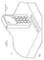
- FIG. 1is a diagram of an embodiment of a handheld computing unit and an extended computing unit in accordance with the present invention
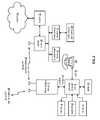
- FIG. 2is a schematic block diagram of an embodiment of a handheld computing unit docked to an extended computing unit within a communication system in accordance with the present invention
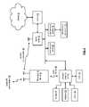
- FIG. 3is a schematic block diagram of an embodiment of a handheld computing unit quasi docked to an extended computing unit within a communication system in accordance with the present invention
- FIG. 4is a schematic block diagram of an embodiment of a handheld computing unit in a remote mode with respect to an extended computing unit within a communication system in accordance with the present invention
- FIG. 5is a schematic block diagram of another embodiment of a computing device where a handheld computing unit is docked to an extended computing unit in accordance with the present invention
- FIG. 6is a schematic block diagram of another embodiment of a computing device where a handheld computing unit is not docked to an extended computing unit in accordance with the present invention
- FIG. 7is a schematic block diagram of an embodiment of a handheld computing unit docked to an extended computing unit in accordance with the present invention.
- FIG. 8is a schematic block diagram of an embodiment of a handheld computing unit quasi docked to an extended computing unit in accordance with the present invention.
- FIG. 9is a schematic block diagram of an embodiment of core components of a handheld computing unit docked to an extended computing unit in accordance with the present invention.
- FIG. 10is a schematic block diagram of an embodiment of a handheld computing unit in accordance with the present invention.
- FIG. 11is a schematic block diagram of an embodiment of an extended computing unit in accordance with the present invention.
- FIG. 12is a schematic block diagram of another embodiment of core components of a handheld computing unit docked to an extended computing unit in accordance with the present invention.
- FIG. 13is a schematic block diagram of another embodiment of a handheld computing unit in accordance with the present invention.
- FIG. 14is a schematic block diagram of another embodiment of an extended computing unit in accordance with the present invention.
- FIG. 15is a schematic block diagram of another embodiment of core components of a handheld computing unit docked to an extended computing unit in accordance with the present invention.
- FIG. 16is a schematic block diagram of another embodiment of a handheld computing unit in accordance with the present invention.
- FIG. 17is a schematic block diagram of another embodiment of an extended computing unit in accordance with the present invention.
- FIG. 18is a schematic block diagram of another embodiment of an extended computing unit in accordance with the present invention.
- FIG. 19is a schematic block diagram of another embodiment of an extended computing unit in accordance with the present invention.
- FIG. 20is a schematic block diagram of another embodiment of a computing device where a handheld computing unit is docked to an extended computing unit in accordance with the present invention
- FIG. 21is a schematic block diagram of another embodiment of a computing device where a handheld computing unit is not docked to an extended computing unit in accordance with the present invention.
- FIG. 22is a schematic block diagram of another embodiment of a computing device where a handheld computing unit is docked to an extended computing unit in accordance with the present invention
- FIG. 23is a schematic block diagram of another embodiment of a computing device where a handheld computing unit is not docked to an extended computing unit in accordance with the present invention.
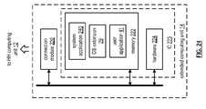
- FIG. 24is a schematic block diagram of another embodiment of an extended computing unit in accordance with the present invention.
- FIG. 1is a diagram of an embodiment of a computing device 10 that includes a handheld computing unit 12 and an extended computing unit 14 .
- the handheld computing unit 12may have a form factor similar to a cellular telephone, personal digital assistant, personal digital audio/video player, etc. and includes a connector structure that couples to a docketing receptacle 16 of the extended computing unit 14 .
- the handheld computing unit 12includes the primary processing module (e.g., central processing unit), the primary main memory, and the primary hard disk memory for the computing device 10 .
- the handheld computing unit 12functions as the core of a personal computer (PC) or laptop computer when it is docked to the extended computing unit and functions as a cellular telephone, a GPS receiver, a personal digital audio player, a personal digital video player, a personal digital assistant, and/or other handheld electronic device when it is not docked to the extended computing unit.
- PCpersonal computer
- laptop computerwhen it is docked to the extended computing unit and functions as a cellular telephone, a GPS receiver, a personal digital audio player, a personal digital video player, a personal digital assistant, and/or other handheld electronic device when it is not docked to the extended computing unit.
- the handheld computing unit 12when the handheld computing unit 12 is docked to the extended computing unit 14 , files and/or applications can be swapped therebetween.
- the user of the computing device 10has created a presentation using presentation software and both reside in memory of the extended computing unit 14 .
- the usermay elect to transfer the presentation file and the presentation software to memory of the handheld computing unit 12 . If the handheld computing unit 12 has sufficient memory to store the presentation file and application, then it is copied from the extended computing unit memory to the handheld computing unit memory. If there is not sufficient memory in the handheld computing unit, the user may transfer an application and/or file from the handheld computing unit memory to the extended computing unit memory to make room for the presentation file and application.
- the handheld computing unit 12including the primary components for the computing device 10 , there is only one copy of an application and/or of a file to support PC functionality, laptop functionality, and a plurality of handheld device functionality (e.g., TV, digital audio/video player, cell phone, PDA, GPS receiver, etc.).
- a plurality of handheld device functionalitye.g., TV, digital audio/video player, cell phone, PDA, GPS receiver, etc.
- special software to transfer the applications and/or files from a PC to a handheld deviceis no longer needed.
- the processing module, main memory, and I/O interfaces of the handheld computing unit 12provide a single core architecture for a PC and/or a laptop, a cellular telephone, a PDA, a GPS receiver, a personal digital audio player, a personal digital video player, etc.
- FIG. 2is a schematic block diagram of an embodiment of a handheld computing unit 12 docked to an extended computing unit 14 within a communication system.
- the communication systemmay include one or more of a wireless local area network (WLAN) router 28 , a modem 36 coupled to the internet 38 , an entertainment server 30 (e.g., a server coupled to database of movies, music, video games, etc.), an entertainment receiver 32 , entertainment components 34 (e.g., speaker system, television monitor and/or projector, DVD (digital video disc) player or newer versions thereof, VCR (video cassette recorder), satellite set top box, cable set top box, video game console, etc.), and a voice over internet protocol (VoIP) phone 26 .
- the systemmay include a local area network (LAN) router coupled to the extended computing unit 14 .
- LANlocal area network
- the extended computing unit 14is coupled to a monitor 18 , a keyboard, a mouse 22 , and a printer 24 .
- the extended computing unit 14may also be coupled to other devices (not shown) such as a trackball, touch screen, gaming devices (e.g., joystick, game pad, game controller, etc.), an image scanner, a webcam, a microphone, speakers, and/or a headset.
- the extended computing unit 14may have a form factor similar to a personal computer and/or a laptop computer. For example, for in-home or in-office use, having the extended computing unit with a form factor similar to a PC may be desirable. As another example, for traveling users, it may be more desirable to have a laptop form factor.
- the handheld computing unit 12is docked to the extended computer unit 14 and function together to provide the computing device 10 .
- the docking of the handheld computing unit 12 to the extended computing unit 14encompasses one or more high speed connections between the units 12 and 14 .
- Such a high speed connectionmay be provided by an electrical connector, by an RF connector, by an electromagnetic connector, and/or a combination thereof.
- the handheld computing unit 12 and the extended computing 14collectively function similarly to a personal computer and/or laptop computer with a WLAN card and a cellular telephone card.
- the handheld computing unit 12may transceive cellular RF communications 40 (e.g., voice and/or data communications).
- Outgoing voice signalsmay originate at the VoIP phone 26 as part of a VoIP communication 44 or a microphone coupled to the extended computing unit 14 .
- the outgoing voice signalsare converted into digital signals that are subsequently converted to outbound RF signals.
- Inbound RF signalsare converted into incoming digital audio signals and that may be provided to a sound card within the extended computing unit for presentation on speakers or provided to the VoIP phone via as part of a VoIP communication 44 .
- Outgoing data signalsmay originate at the mouse 22 , keyboard 20 , image scanner, etc. coupled to the extended computing unit 14 .
- the outgoing data signalsare converted into digital signals that are subsequently converted to outbound RF signals.
- Inbound RF signalsare converted into incoming data signals and that may be provided to the monitor 18 , the printer 24 , and/or other character presentation device.
- the handheld computing unit 12may provide a WLAN transceiver for coupling to the WLAN router 28 to support WLAN RF communications 42 for the computing device 10 .
- the WLAN communications 42may be for accessing the internet 38 via modem 36 , for accessing the entertainment server, and/or accessing the entertainment receiver 32 .
- the WLAN communications 42may be used to support surfing the web, receiving emails, transmitting emails, accessing on-line accounts, accessing on-line games, accessing on-line user files (e.g., databases, backup files, etc.), downloading music files, downloading video files, downloading software, etc.
- the computing device 10may use the WLAN communications 42 to retrieve and/or store music and/or video files on the entertainment server; and/or to access one or more of the entertainment components 34 and/or the entertainment receiver 32 .
- FIG. 3is a schematic block diagram of an embodiment of a handheld computing unit 12 quasi docked to an extended computing unit 14 within a communication system.
- the communication systemmay include one or more of a wireless local area network (WLAN) router 28 , a modem 36 coupled to the internet 38 , an entertainment server 30 (e.g., a server coupled to database of movies, music, video games, etc.), an entertainment receiver 32 , entertainment components 34 (e.g., speaker system, television monitor and/or projector, DVD (digital video disc) player or newer versions thereof, VCR (video cassette recorder), satellite set top box, cable set top box, video game console, etc.), and a voice over internet protocol (VoIP) phone 26 .
- the systemmay include a local area network (LAN) router coupled to the extended computing unit 14 .
- LANlocal area network
- the extended computing unit 14is coupled to a monitor 18 , a keyboard, a mouse 22 , and a printer 24 .
- the extended computing unit 14may also be coupled to other devices (not shown) such as a trackball, touch screen, gaming devices (e.g., joystick, game pad, game controller, etc.), an image scanner, a webcam, a microphone, speakers, and/or a headset.
- the extended computing unit 14may have a form factor similar to a personal computer and/or a laptop computer.
- the handheld computing unit 12is quasi docked 46 to the extended computer unit 14 , where the handheld computing unit 12 functions as a stand-alone computer with limited resources (e.g., processing modules, user inputs/outputs, main memory, etc. of the handheld computing unit) and limited access to the memory of the extended computing unit 14 .
- the quasi docking 46 of the handheld computing unit 12 to the extended computing unit 14is provided by an RF communication, where an RF transceiver of the handheld computing unit 12 is communicating with an RF transceiver of the extended computing unit 14 .
- the handheld computing unitcan access files and/or applications stored in memory of the extended computing unit 14 .
- the handheld computing unit 12may direct the processing module of the extended computing unit 14 to perform a remote co-processing function, but the processing module of the handheld computing unit and the extended computing unit do not function as a multiprocessing module as they do when in the docked mode.
- the quasi docked modemay be achieved by the handheld computing unit 12 communicating with the extended computing unit via the WLAN communication 42 and the WLAN router 28 .
- the quasi docked modemay be achieved via a data cellular RF communication 40 via the internet 38 to the extended computing unit 14 .
- the handheld computing unit 12may transceive cellular RF communications 40 (e.g., voice and/or data communications).
- Outgoing voice signalsoriginate at a microphone of the handheld computing unit 12 .
- the outgoing voice signalsare converted into digital signals that are subsequently converted to outbound RF signals.
- Inbound RF signalsare converted into incoming digital audio signals and that are provided to a speaker, or headphone jack, of the handheld computing unit 12 .
- Outgoing data signalsoriginate at a keypad or touch screen of the handheld computing unit 12 .
- the outgoing data signalsare converted into digital signals that are subsequently converted to outbound RF signals.
- Inbound RF signalsare converted into incoming data signals that are provided to the handheld display and/or other handheld character presentation device.
- the handheld computing unit 12may provide a WLAN transceiver for coupling to the WLAN router 28 to support WLAN RF communications 42 with the WLAN router 28 .
- the WLAN communications 42may be for accessing the internet 38 via modem 36 , for accessing the entertainment server, and/or accessing the entertainment receiver 32 .
- the WLAN communications 42may be used to support surfing the web, receiving emails, transmitting emails, accessing on-line accounts, accessing on-line games, accessing on-line user files (e.g., databases, backup files, etc.), downloading music files, downloading video files, downloading software, etc.
- the handheld computing unit 12may use the WLAN communications 42 to retrieve and/or store music and/or video files on the entertainment server; and/or to access one or more of the entertainment components 34 and/or the entertainment receiver 32 .
- FIG. 4is a schematic block diagram of an embodiment of a handheld computing unit 12 in a remote mode with respect to an extended computing unit 14 .
- the handheld computing unit 12has no communications with the extended computing unit 14 .
- the extended computing unit 14is disabled and the handheld computing unit 12 functions as a stand-alone computing device.
- FIG. 5is a schematic block diagram of another embodiment of a computing device 10 that includes a handheld computing unit 12 docked, or quasi-docked, with an extended computing unit 14 .
- the computing device 10includes computer level applications 39 , computer level application programming interfaces (API) 33 , a computer level operating system 27 , and computer level hardware 21 .
- the computer level applications 39include system applications (e.g., input/output device drivers, peripheral device drivers, printer spoolers, video graphics, etc.) and user applications (e.g., database programs, word processing programs, spreadsheet programs, audio playback programs, video playback programs, etc.).
- the hardware 21 portion of the computing device 10includes core hardware 23 on the handheld (HH) computing unit 12 and hardware 25 of the EXT computing unit 14 .
- the hardware of the HH computing unit 12may include one or more of: a radio frequency (RF) section, a baseband processing module, a hard disk and/or flash memory, main memory, a processing module, RAM, ROM, clock circuitry, an audio IO interface, a video IO interface, a data IO interface, and may further include a memory controller.
- RFradio frequency
- the hardware 25 of the EXT computing unit 14may include one or more of: a hard disk and/or flash memory, main memory, a co-processing module, RAM, ROM, slave clock circuitry, an audio IO interface, a video IO interface, a data IO interface, and may further include a memory controller.
- the hardware of the HH computing unit 12is the core hardware of the computing device 10 and the hardware of the EXT computing unit 14 provides an extension of the HH hardware 23 .
- the processing module of the HH computing unit 12may use the processing module of the EXT computing unit 14 as a co-processor, as an auxiliary processor, as part of a multiple-processor core, or not use it at all.
- the HH computing unit 12may use the main memory of the EXT computing unit 14 as an extension of its main memory, as an auxiliary main memory (e.g., use as a backup copy), as a second layer of cache (e.g., L1 or L2 cache), or not use it at all.
- the operating system 27includes a core operating system 29 stored in memory of the HH computing device 12 and an operating system extension 31 stored on the EXT computing unit 14 .
- the operating system of the computing device 10is discussed in detail with reference to FIGS. 20-36 of the parent application referenced above.
- the core operating system 29provides the primary operating system for the computing device 10 and the EXT operating system 31 augments the primary operating system for further functionality when the HH computing unit 12 is docked to the EXT computing unit 14 .
- the computer level API 33includes APIs 35 that are stored on the HH computing unit 12 and APIs 37 that are stored on the EXT computing unit 14 .
- the computer level applications 39include applications 41 that are stored on the HH computing unit 12 and applications 43 stored on the EXT computing unit 14 .
- applicationsmay reside on the handheld computing unit 12 (e.g., cellular telephone applications) or on the extended computing unit 14 .
- the applicationsmay be swapped therebetween such that, when the HH computing unit 12 is not docked to the EXT computing unit 14 , the HH computing unit 12 can store the applications 39 of interest to the user of the HH computing device 12 in a mobile mode (i.e., not docked).
- FIG. 6is a schematic block diagram of another embodiment of a computing device 10 where the handheld computing unit 12 is not docked to an extended computing unit 14 .
- HH computing unit 12functions as a stand-alone mobile device while the EXT computing unit 14 is substantially non-operational.
- the architecture of the HH computing unit 12includes vertical functional coupling of the hardware 23 , the operating system 29 , the API 35 , and the applications 41 .
- the EXT computing unit 14does not include vertical functional coupling since each of the blocks (e.g., hardware 25 , operating system 31 , API 37 , and applications 43 ) are extensions of the corresponding blocks of the HH computing unit 12 .
- FIG. 5there is only one hardware core and one operating system for a computing device 10 that operates in a docked mode (e.g., FIG. 5 ) similarly to a personal computer and in a non-docked or mobile manner (e.g., FIG. 6 ) similarly to a cellular telephone with personal digital assistance capabilities, digital audio player capabilities, digital video player capabilities, handheld computing capabilities, and/or other mobile computing capabilities.
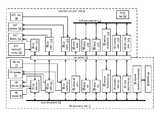
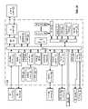
- FIG. 7is a schematic block diagram of an embodiment of a handheld computing unit 12 docked to an extended computing unit 14 .
- the handheld computing unit 12includes a handheld processing module 50 , handheld main memory 52 , handheld hard disk/flash memory 54 , a baseband processing module 56 , a radio frequency (RF) section 58 , handheld random access memory (RAM) 60 , handheld read only memory (ROM) 62 , a clock generator circuit 64 , handheld input/output (I/O) interfaces (e.g., handheld audio I/O interface 66 , handheld video and/or graphics interface 68 , and handheld data I/O interface 70 ), and handheld I/O components (e.g., handheld microphone 72 , handheld speaker 74 , handheld display 76 , and a handheld keypad and/or touch screen 78 ), a handheld bus structure 75 , and a handheld connection structure 110 .
- I/Ohandheld input/output
- the extended computing unit 14includes an extended processing module 80 , extended main memory 82 , extended hard disk/flash memory 84 , extended random access memory (RAM) 86 , extended read only memory (ROM) 88 , a slave clock circuit 90 , extended input/output (I/O) interfaces (e.g., extended audio I/O interface 92 , extended video and/or graphics interface 94 , and an extended data I/O interface 96 ), and extended I/O components (e.g., extended microphone 98 , extended speaker 100 , extended display 102 —which may be monitor 18 and/or printer 24 —, and an extended keyboard/mouse 104 , which may be keyboard 20 and mouse 22 ), an extended connection structure 110 , an extended bus structure 112 , and a radio frequency identification (RFID) tag 108 .
- RFIDradio frequency identification
- the processing module 50 and the baseband processing module 56may be separate processing modules or the same processing module.
- a processing modulemay be a single processing device or a plurality of processing devices, where a processing device may be a microprocessor, micro-controller, digital signal processor, microcomputer, central processing unit, field programmable gate array, programmable logic device, state machine, logic circuitry, analog circuitry, digital circuitry, and/or any device that manipulates signals (analog and/or digital) based on hard coding of the circuitry and/or operational instructions.
- the processing modulemay have an associated memory and/or memory element, which may be a single memory device, a plurality of memory devices, and/or embedded circuitry of the processing module.
- Such a memory devicemay be a read-only memory, random access memory, volatile memory, non-volatile memory, static memory, dynamic memory, flash memory, cache memory, and/or any device that stores digital information.
- the processing moduleimplements one or more of its functions via a state machine, analog circuitry, digital circuitry, and/or logic circuitry
- the memory and/or memory element storing the corresponding operational instructionsmay be embedded within, or external to, the circuitry comprising the state machine, analog circuitry, digital circuitry, and/or logic circuitry.
- the memory elementstores, and the processing module executes, hard coded and/or operational instructions corresponding to at least some of the steps and/or functions illustrated in FIGS. 1-24 .
- the handheld main memory 52includes one or more RAM integrated circuits (IC) and/or boards.
- the RAMmay be static RAM (SRAM) and/or dynamic RAM (DRAM).
- the handheld hard disk/flash memory 54may be one or more of a hard disk, a floppy disk, an optical disk, NOR flash memory, NAND flash memory, and/or any other type of non-volatile memory.
- the clock generator circuit 64may be one or more of: a phase locked loop, a crystal oscillator circuit, a fractional-N synthesizer, and/or a resonator circuit-amplifier circuit, where the resonator may be a quartz piezo-electric oscillator, a tank circuit, or a resistor-capacitor circuit. Regardless of the implementation of the clock generator circuit 64 , it generates a master clock signal that is provided to the slave clock circuit 90 and generates the clock signals for the handheld computing unit 12 . Such clock signals include, but are not limited to, a bus clock, a read/write clock, a processing module clock, a local oscillation, and an I/O clock.
- the handheld ROM 62stores the basic input/output system (BIOS) program for the computing device 10 (i.e., the handheld computing unit 12 and the extended computing unit 14 ).
- the ROM 62may be one or more of an electronically erasable programmable ROM (EEPROM), a programmable ROM (PROM), and/or a flash ROM.
- EEPROMelectronically erasable programmable ROM
- PROMprogrammable ROM
- flash ROMflash ROM
- an interfaceincludes hardware and/or software for a device coupled thereto to access the bus of the handheld computing unit and/or of the extended computing unit.
- the interface softwaremay include a driver associated with the device and the hardware may include a signal conversion circuit, a level shifter, etc.
- the handheld audio I/O interface 66may include an audio codec, a volume control circuit, and/or a microphone bias and/or amplifier circuit to couple the handheld (HH) microphone 72 and/or the HH speaker 74 to the HH bus structure 75 .
- the HH video I/O interface 68may include a video codec, a graphics engine, a display driver, etc. to couple the HH display to the HH bus structure 75 .
- the HH data I/O interface 70may include the graphics engine, a display driver, a keypad driver, a touch screen driver, etc. to coupled the HH display 76 and/or the HH keypad 78 to the HH bus structure 75 .
- the extended (EXT) processing module 80may be a single processing device or a plurality of processing devices, where a processing device may be a microprocessor, micro-controller, digital signal processor, microcomputer, central processing unit, field programmable gate array, programmable logic device, state machine, logic circuitry, analog circuitry, digital circuitry, and/or any device that manipulates signals (analog and/or digital) based on hard coding of the circuitry and/or operational instructions.
- the processing modulemay have an associated memory and/or memory element, which may be a single memory device, a plurality of memory devices, and/or embedded circuitry of the processing module.
- Such a memory devicemay be a read-only memory, random access memory, volatile memory, non-volatile memory, static memory, dynamic memory, flash memory, cache memory, and/or any device that stores digital information.
- the processing moduleimplements one or more of its functions via a state machine, analog circuitry, digital circuitry, and/or logic circuitry
- the memory and/or memory element storing the corresponding operational instructionsmay be embedded within, or external to, the circuitry comprising the state machine, analog circuitry, digital circuitry, and/or logic circuitry.
- the memory elementstores, and the processing module executes, hard coded and/or operational instructions corresponding to at least some of the steps and/or functions illustrated in FIGS. 1-24 .
- the EXT main memory 86includes one or more RAM integrated circuits (IC) and/or boards.
- the RAMmay be static RAM (SRAM) and/or dynamic RAM (DRAM).
- SRAMstatic RAM
- DRAMdynamic RAM
- the EXT main memory 86 and the EXT RAM 86may be omitted if the handheld computing unit contains a sufficient amount of main memory.
- the EXT hard disk/flash memory 84may be one or more of a hard disk, a floppy disk, at tape drive, an optical disk, NOR flash memory, NAND flash memory, and/or any other type of non-volatile memory.
- the slave clock circuit 90may be a phase locked loop (PLL), clock divider, and/or clock multiplier that receives the master clock signal and produces therefrom the clock signals for the extended computing unit 14 .
- Such clock signalsinclude, but are not limited to, a bus clock, a read/write clock, a processing module clock, and an I/O clock.
- the EXT ROM 88may be one or more of an electronically erasable programmable ROM (EEPROM), a programmable ROM (PROM), and/or a flash ROM. Note that the EXT ROM 88 may be omitted if the HH ROM 62 is of sufficient size to accommodate the BIOS program and other system data that is stored in non-volatile memory.
- EEPROMelectronically erasable programmable ROM
- PROMprogrammable ROM
- flash ROMflash ROM
- the EXT audio I/O interface 92may include a sound card and corresponding driver to couple the EXT microphone 98 and/or the EXT speaker 100 to the HH and/or EXT bus structure 75 and/or 112 .
- the EXT video I/O interface 94may include a video codec, a graphics card, a graphics control unit, a display driver, etc. to couple the EXT display 102 (e.g., monitor 18 ) to the HH and/or EXT bus structure 75 and/or 112 .
- the EXT data I/O interface 98may include the graphics card, the graphics control unit, a display driver, a keyboard and mouse driver(s), a touch screen driver, etc. to coupled the EXT display 104 and/or the EXT keyboard/mouse 104 to the HH and/or EXT bus structure 75 and/or 112 .
- the RFID tag 108provides an RF communication link to the handheld computing unit 12 when the extended computing unit 14 is disabled.
- the RFID tag 108may be implemented as disclosed in co-pending patent application entitled POWER GENERATING CIRCUIT, having a Ser. No. 11/394,808, and a filing date of Mar. 31, 2006.
- the baseband processing module 56 and the RF section 58are active.
- the baseband processing module 56converts an outbound voice signal into an outbound voice symbol stream in accordance with one or more existing wireless communication standards, new wireless communication standards, modifications thereof, and/or extensions thereof (e.g., GSM, AMPS, digital AMPS, CDMA, etc.).
- the baseband processing module 56may perform one or more of scrambling, encoding, constellation mapping, modulation, frequency spreading, frequency hopping, beamforming, space-time-block encoding, space-frequency-block encoding, and/or digital baseband to IF conversion to convert the outbound voice signal into the outbound voice symbol stream.
- the baseband processing module 56may generate the outbound voice symbol stream as Cartesian coordinates (e.g., having an in-phase signal component and a quadrature signal component to represent a symbol), as Polar coordinates (e.g., having a phase component and an amplitude component to represent a symbol), or as hybrid coordinates as disclosed in co-pending patent application entitled HYBRID RADIO FREQUENCY TRANSMITTER, having a filing date of Mar. 24, 2006, and an application Ser. No. 11/388,822, and co-pending patent application entitled PROGRAMMABLE HYBRID TRANSMITTER, having a filing date of Jul. 26, 2006, and an application Ser. No. 11/494,682.
- Cartesian coordinatese.g., having an in-phase signal component and a quadrature signal component to represent a symbol
- Polar coordinatese.g., having a phase component and an amplitude component to represent a symbol
- hybrid coordinatesas disclosed in co-pending patent application entitled HYBRID RADIO F
- the RF section 58converts the outbound voice symbol stream into an outbound RF voice signal in accordance with the one or more existing wireless communication standards, new wireless communication standards, modifications thereof, and/or extensions thereof (e.g., GSM, AMPS, digital AMPS, CDMA, etc.).
- the RF section 58receives the outbound voice symbol stream as Cartesian coordinates.
- the RF section 58mixes the in-phase components of the outbound voice symbol stream with an in-phase local oscillation to produce a first mixed signal and mixes the quadrature components of the outbound voice symbol stream to produce a second mixed signal.
- the RF section 58combines the first and second mixed signals to produce an up-converted voice signal.
- the RF section 58then amplifies the up-converted voice signal to produce the outbound RF voice signal, which it provides to an antenna section. Note that further power amplification may occur between the output of the RF section 58 and the input of the antenna section.
- the RF section 58receives the outbound voice symbol stream as Polar or hybrid coordinates. In these embodiments, the RF section 58 modulates a local oscillator based on phase information of the outbound voice symbol stream to produce a phase modulated RF signal. The RF section 58 then amplifies the phase modulated RF signal in accordance with amplitude information of the outbound voice symbol stream to produce the outbound RF voice signal. Alternatively, the RF section 58 may amplify the phase modulated RF signal in accordance with a power level setting to produce the outbound RF voice signal.
- the RF section 58receives an inbound RF voice signal via the antenna section.
- the RF section 58converts the inbound RF voice signal into an inbound voice symbol stream.
- the RF section 58extracts Cartesian coordinates from the inbound RF voice signal to produce the inbound voice symbol stream.
- the RF section 58extracts Polar coordinates from the inbound RF voice signal to produce the inbound voice symbol stream.
- the RF section 58extracts hybrid coordinates from the inbound RF voice signal to produce the inbound voice symbol stream.
- the baseband processing module 56converts the inbound voice symbol stream into an inbound voice signal.
- the baseband processing module 56may perform one or more of descrambling, decoding, constellation demapping, modulation, frequency spreading decoding, frequency hopping decoding, beamforming decoding, space-time-block decoding, space-frequency-block decoding, and/or IF to digital baseband conversion to convert the inbound voice symbol stream into the inbound voice signal, which is placed on the bus structure 75 .
- the baseband processing module 56 and the RF sectionfunction similarly for processing data communications and for processing WLAN communications.
- the baseband processing module 56 and the RF sectionfunction in accordance with one or more cellular data protocols such as, but not limited to, Enhanced Data rates for GSM Evolution (EDGE), General Packet Radio Service (GPRS), high-speed downlink packet access (HSDPA), high-speed uplink packet access (HSUPA), newer version thereof, and/or replacements thereof.
- EDGEEnhanced Data rates for GSM Evolution
- GPRSGeneral Packet Radio Service
- HSDPAhigh-speed downlink packet access
- HSUPAhigh-speed uplink packet access
- newer version thereofand/or replacements thereof.
- the baseband processing module 56 and the RF section 58function in accordance with one or more wireless communication protocols such as, but not limited to, IEEE 802.11(a), (b), (g), (n), etc., Bluetooth, ZigBee, RFID, etc.
- the HH processing module 50 and the EXT processing module 80function as a multiprocessing module and the HH and EXT main memories 52 and 82 function as combined main memory.
- the HH hard disk/flash memory 54 and the EXT hard disk/flash memory 84function as a combined hard disk/flash memory.
- the multiprocessing moduleprovides multiprocessing via the HH and EXT processing modules 50 and 80 .
- the processing modules 50 and 80may share tasks and/or execute multiple concurrent software processes.
- the processing modules 50 and 80may be equal; one may be reserved for one or more special purposes; may be tightly coupled; may be loosely coupled; etc.
- the HH processing module 50may be designated to respond to all interrupts, traps, and/or services calls and the invoke the EXT processing module 80 as needed.
- the processing modulesmay function in a symmetrical multiprocessing mode, in an asymmetrical multiprocessing mode, in a non-uniform memory access multiprocessing mode, and/or in a clustered multiprocessing mode.
- the processing modules 50 and 80may execute a single sequence of instructions in multiple contexts (single-instruction, multiple-data or SIMD), multiple sequences of instructions in a single context (multiple-instruction, single-data or MISD), or multiple sequences of instructions in multiple contexts (multiple-instruction, multiple-data or MIMD).
- the computing device 10incorporates a virtual memory technique, overlays, and/or swapping to utilize the combined main memories and hard disk/flash memories for one or more user applications.
- the virtual memoryis divided the virtual address space into pages (e.g., a 4K-Byte block), where one or more page tables (e.g., one for the computing device, one for each running user application, etc.) translates the virtual address into a physical address.
- the memory controllermanages accesses to the one or more page tables to facilitate the fetching of data and/or instructions from physical memory. If a page table indicates that a page is not currently in memory, the memory controller and/or one of the processing modules 50 and/or 80 raise a page fault interrupt.
- a paging supervisor of the operating systemreceives the page fault interrupt and, in response, searches for the desired page containing the required virtual address. Once found, the paging supervisor reads the page into main memory and updates the appropriate page table. If there is insufficient room the main memory, the paging supervisor saves an area of the main memory to the HH or EXT hard disk/flash memory and update the corresponding page table. The cleared area of main memory is then used for the new page.
- the HH microphone 72 , the HH speaker 74 , the HH display 76 and the HH keypad 78may be disabled while the handheld computing unit is docked.
- the EXT microphone 98 , the EXT speaker 100 , the EXT display 102 , and the EXT keyboard/mouse 104are active to provide the user interfaces to the computing device 10 .
- the inbound and outbound voice signalsmay be provided to/from the EXT microphone 98 and the speaker 100 , an EXT headset (not shown), or the VoIP phone 46 .
- FIG. 8is a schematic block diagram of an embodiment of a handheld computing unit 12 quasi docked to an extended computing unit 14 .
- the handheld computing unit 12includes a handheld processing module 50 , handheld main memory 52 , handheld hard disk/flash memory 54 , a baseband processing module 56 , a radio frequency (RF) section 58 , handheld random access memory (RAM) 60 , handheld read only memory (ROM) 62 , a clock generator circuit 64 , handheld input/output (I/O) interfaces (e.g., handheld audio I/O interface 66 , handheld video and/or graphics interface 68 , and handheld data I/O interface 70 ), and handheld I/O components (e.g., handheld microphone 72 , handheld speaker 74 , handheld display 76 , and a handheld keypad and/or touch screen 78 ), a handheld bus structure 75 , and a handheld connection structure 110 A.
- I/Ohandheld input/output
- the extended computing unit 14includes an extended processing module 80 , extended main memory 82 , extended hard disk/flash memory 84 , extended random access memory (RAM) 86 , extended read only memory (ROM) 88 , a slave clock circuit 90 , extended input/output (I/O) interfaces (e.g., extended audio I/O interface 92 , extended video and/or graphics interface 94 , and an extended data I/O interface 96 ), and extended I/O components (e.g., extended microphone 98 , extended speaker 100 , extended display 102 —which may be monitor 18 and/or printer 24 —, and an extended keyboard/mouse 104 , which may be keyboard 20 and mouse 22 ), an extended connection structure 110 B, an extended bus structure 112 , an RFID tag 108 , a baseband processing module 114 , and an RF section 116 .
- the EXT processing module 80 and the baseband processing module 114may be separate processing modules or the same processing module.
- the baseband processing module 114 and the RF section 58 for the extended computing unit 14establish an RF communication path 46 with the RF section 58 and the baseband processing module 56 of the handheld computing unit 12 .
- the RF communication path 46is essentially functioning as a wireless bus coupling the HH bus structure 75 to the EXT bus structure 112 such that the handheld computing unit 12 may access the EXT main memory 82 and/or the EXT hard disk/flash memory of the extended computing unit 14 .
- the baseband processing modules 56 and 114 and the RF sections 58 and 116may utilize a wireless communication protocol such as, but not limited to, IEEE 802.11(a), (b), (g), (n), etc., Bluetooth, ZigBee, RFID, etc.
- a wireless communication protocolsuch as, but not limited to, IEEE 802.11(a), (b), (g), (n), etc., Bluetooth, ZigBee, RFID, etc.
- the HH processing module 50executes one or more user applications (e.g., word processing, spreadsheet processing, presentation processing, email, web browsing, database, calendar, video games, digital audio playback, digital video playback, digital audio record, digital video record, video games, contact management program, notes, web favorites, money management program, etc.) using the HH main memory 52 .
- the EXT processing module 80 and the EXT main memoryare inactive except to facilitate read/write functions to the EXT hard disk/flash memory 84 , which is treated as a lower level memory than the HH hard disk/flash memory 54 .
- the virtual memory techniqueutilizes the HH main memory 52 and the HH hard disk/flash memory 54 for one or more user applications. Further memory management includes copying user applications and/or files from the EXT hard disk/flash memory 84 to the HH hard disk/flash memory 54 before it can be included in virtual memory and hence accessed by the HH processing module 50 . Note that if the HH hard disk/flash memory 54 does not have sufficient space to store the user applications and/or files, the one or more user applications and/or files are transferred from the HH hard disk/flash memory 54 to the EXT hard disk/flash memory 84 to free up memory space.
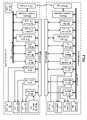
- FIG. 9is a schematic block diagram of an embodiment of core components of a handheld computing unit 12 docked to an extended computing unit 14 .
- the core components of the handheld computing unit 12include the HH processing module 50 , the HH main memory 52 , the HH hard disk/flash memory 54 , the baseband processing module 56 , the RF section 58 , the ROM 62 , a universal serial bus (USB) interface 120 , and the handheld connection structure 110 A, which may be a combined connector or a plurality of connectors 110 - 1 through 110 - 5 .
- USBuniversal serial bus
- the core components of the extended computing unit 14include the corresponding connection structure 110 B, one or more EXT processing modules 80 , the EXT main memory 82 , the slave clock module 90 , a memory controller 122 , a graphics card 128 and/or a graphics processing unit 132 , an I/O controller 130 , an I/O interface 134 , a peripheral component interconnect (PCI) interface 136 , and a host controller 138 .
- PCIperipheral component interconnect
- the core components of units 12 and 14function as a single computing device 10 .
- the BIOS stored on the HH ROM 62is executed to boot up the computing device. After initializing the operating system the computing device 10 is ready to execute a user application.
- the memory controller 122coordinates the reading data from and writing data to the HH main memory 52 and the EXT main memory 82 , by the processing modules 50 and 80 , by the user I/O devices coupled directly or indirectly to the I/O controller, by the graphics card 128 , and/or for data transfers with the HH and/or EXT hard disk/flash memory 54 and/or 84 .
- the HH main memory 52 and/or the EXT main memoryinclude DRAM
- the memory controller 122includes logic circuitry to refresh the DRAM.
- the I/O controller 130provides access to the memory controller 122 for typically slower devices.
- the I/O controller 130provides functionality for the PCI bus via the PCI interface 136 ; for the I/O interface 134 , which may provide the interface for the keyboard, mouse, printer, and/or a removable CD/DVD disk drive; and BIOS interface; a direct memory access (DMA) controller, interrupt controllers, a host controller, which allows direct attached of the EXT hard disk memory; a real time clock, an audio interface.
- the I/O controller 130may also include support for an Ethernet network card, a Redundant Arrays of Inexpensive Disks (RAID), a USB interface, and/or FireWire.
- RAIDRedundant Arrays of Inexpensive Disks
- the graphics processing unit (GPU) 132is a dedicated graphics rendering device for manipulating and displaying computer graphics.
- the GPUimplements a number of graphics primitive operations and computations for rendering two-dimensional and/or three-dimensional computer graphics. Such computations may include texture mapping, rendering polygons, translating vertices, programmable shaders, aliasing, and very high-precision color spaces.
- the GPU 132may a separate module on a video card or it may be incorporated into the graphics card 128 that couples to the memory controller 122 via the accelerated graphics port (AGP).
- AGPaccelerated graphics port
- a video card, or graphics acceleratorfunctions to generate the output images for the EXT display.
- the video cardmay further include functionality to support video capture, TV tuner adapter, MPEG-2 and MPEG-4 decoding or FireWire, mouse, light pen, joystick connectors, and/or connection to two monitors.
- the EXT processing module 80 , the memory controller 122 , the EXT main memory 82 , the I/O controller 130 , the I/O interface 134 , the PCI interface 136 , and the host controller 138may be implemented on a single integrated circuit, each on separate integrated circuits, or some elements may be implemented on the same integrated circuits.
- the EXT processing module 80 and the memory controller 122may be implemented on the same integrated circuit.
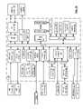
- FIG. 10is a schematic block diagram of an embodiment of a handheld computing unit 12 that may be used in the computing device 10 of FIG. 9 .
- the handheld computing unit 12includes an integrated circuit (IC) 140 , the HH keypad, the HH display, the HH hard disk/flash memory 54 , the HH main memory 52 , the HH speaker 74 , the HH microphone 72 , the connection structure 110 - 1 A through 110 - 5 A, an antenna section 178 , and may further include an off-chip ROM 63 .
- ICintegrated circuit
- the IC 140includes the bus structure 75 , the HH processing module 50 , the baseband processing module 56 , the RF section 58 , the ROM 62 , the clock generator circuit 64 , a data input interface 142 , a display interface 144 , a video codec 146 (optional), a mobile industry processor interface (MIPI) interface 148 (optional), an arbitration module 150 , a USB interface 120 , a graphics engine 152 , a secure digital input/output (SDIO) interface 154 , a hard disk/flash memory interface 156 , a main memory interface 158 , a direct memory access (DMA) module 160 , an audio codec 162 , a demultiplexer 168 , a plurality of peripheral interfaces 162 - 164 , a digital camera interface 170 , an LCD interface 172 , a security boot ROM 174 (which may be included in ROM 62 or a separate ROM), and a security engine 176 .
- the plurality of peripheral interfaces 162 - 164include two or more of: a SIM (Security Identification Module) card interface, a power management (PM) interface, a SD (Secure Digital) card or MMC (Multi Media Card) interface, a coprocessor interface, a Bluetooth (BT) transceiver interface, an FM tuner interface, a GPS receiver interface, a video sensor interface (e.g., a camcorder), a TV tuner interface, a universal subscriber identity module (USIM) interface, a second display interface, a Universal Asynchronous Receiver-Transmitter (UART) interface, a real time clock, and a general purpose I/O interface.
- SIMSecurity Identification Module
- PMpower management
- SDSecure Digital
- MMCMulti Media Card
- BTBluetooth
- FM tuner interfaceFM tuner interface
- GPS receiver interfacee.g., a GPS receiver
- video sensor interfacee.g., a camcorder
- TV tuner interfacee.g.,
- the HH processing module 50When the handheld computing unit 12 is docked with the extended computing unit 14 , the HH processing module 50 , the HH main memory 52 , the HH hard disk/flash memory 54 , the ROM 62 , the clock generator circuit 64 , and the HH bus structure 75 are coupled directly or indirectly to the memory controller 122 and/or the I/O controller 130 of the extended computing unit 14 .
- a docked mode operating systemmay activate as many or as few of the interfaces of the IC 140 .
- the docked mode operating systemmay deactivate the data input interface 142 , the display interface 144 , the video codec 146 , if included, the audio codec 162 , the graphics engine 152 , and the MIPI interface 148 , if included.
- the docked mode operating systemmay evoke the security functions provided by the security engine 176 and/or the security boot ROM 174 .
- the securitymay be to allow/disallow access to certain resources (e.g., processing modules 50 and/or 80 , files, privileged services calls, certain memory locations, etc.) based on the identity of the requestor. This may be done via an internal security process.
- internal securityprotects the computer's resources from the programs that are concurrently running.
- less privileged programsare blocked from certain instructions (e.g., read from or write to memory) and have to ask a higher privileged program to perform the instruction for it (e.g., an operating system kernel).
- the docked mode operating systemmay active or deactivate one or more of the memory interfaces 156 - 158 depending on whether access to the HH main memory 52 and/or the HH hard disk/flash memory 54 is to be accessed via the HH bus structure 75 and/or via the memory controller 122 and/or the host controller 138 .
- memory interface 158may be activated such that the HH processing module 50 may access the HH main memory 52 via the bus 75 and memory interface 156 may be deactivated such that the HH hard disk/flash memory 54 is accessed via the host controller 138 .
- a remote mode operating systemWhen the handheld computing unit 12 is in the remote mode, a remote mode operating system is active, which activates one or more of the interfaces.
- the remote mode operating systemwill active the data input interface 142 , the display interface 144 , the audio codec 162 , the graphics engine 152 , the video codec 146 , if included, and the MIPI interface 148 , if included, to provide the user with character (e.g., voice, audio, video, image, text, graphics, etc.) input and output functionality via the handheld computing unit 12 .
- the graphic engine 152render two-dimensional and/or three-dimensional graphics for display on the HH display 76 and/or storage in memory 52 and/or 54 .
- the HH display 76may include one or more display devices such as a liquid crystal (LCD) display, a plasma display, a digital light project (DLP) display, and/or any other type of portable video display. Accordingly, the display interface 144 would include software to facilitate the transfer of output video, graphics, and/or text to the HH display 76 . Note that the MIPI interface may be used as an interface for a second HH display or instead of the display interface 144 .
- LCDliquid crystal
- DLPdigital light project
- the remote mode operating systemmay activate the DMA module 160 such that one or more of the other interfaces may provide direct access to the HH main memory 52 without, or with minimal, involvement of the HH processing module 50 .
- the camera interface 170may be provided direct memory access to store a captured image and/or a captured video in the HH main memory 52 or in the HH hard disk/flash memory 54 .
- the HH bus structure 75may include one or more data lines, one or more instruction lines, and/or one or more control lines.
- the HH bus structure 75may include 16-128 lines for data and another 16-128 lines for instructions.
- the HH bus structure 75may further include address lines for addressing the main memory 52 .
- connections from the IC 140 to the connector 110 and/or to other components of the handheld computing unit 12may be done via IC pins, via an RF interconnection, and/or a magnetic interconnection.
- Such an RF interconnectionmay be implemented as disclosed in co-pending patent applications (1) RF BUS CONTROLLER, having a Ser. No. 11/700,285, and a filing date of Jan. 31, 2007; (2) INTRA-DEVICE RF BUS AND CONTROL THEREOF, having a Ser. No. 11/700,421, and a filing date of Jan. 31, 2007; (3) SHARED RF BUS STRUCTURE, having a Ser. No. 11/700,517, and a filing date of Jan.
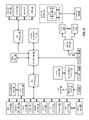
- FIG. 11is a schematic block diagram of an embodiment of an extended computing unit 14 that may be used in the computing device 10 of FIG. 9 .
- the extended computing unit 14includes one or more monitors 18 - 1 through 18 - 2 , the keyboard 20 , the mouse 22 , the printer 24 , the EXT processing module 80 , the EXT main memory 82 , the EXT hard disk/flash/tape memory 84 , the memory controller 122 , the graphics card 128 and/or the graphics processing unit 132 , the I/O controller 130 , the I/O interface 134 , the PCI interface 136 , and the connector structure 110 - 1 B through 110 - 5 B.
- the extended computing unit 14may further include one or more of a CD/DVD removable drive 186 , a flash ROM 188 , flash memory 190 , a disk array controller 192 , a network card 194 , a USB connector 196 , a WLAN transceiver 198 (e.g., baseband processing module 114 and RF section 116 ), a sound card 200 , an infrared (IR) transceiver 202 , a television (TV) tuner 204 , a video processing module 206 , and one or more memory expansion cards 208 .
- the EXT main memory 82may include a plurality of RAM ICs and/or RAM expansion cards 162 - 164 .
- the EXT bus structure 112includes an AGP bus 210 that couples the graphics card 128 to the memory controller 122 , a memory bus that couples the memory controller 122 to the EXT main memory 82 , a processor bus that couples the memory controller 122 to the EXT processing module 80 , a PCI bus that couples a plurality of devices (e.g., devices 190 - 208 ) to the I/O controller 130 via the PCI interface 136 , and an I/O bus that couples traditional I/O devices (e.g., keyboard 20 , mouse 22 , printer 24 , and/or removable drive 186 ) to the I/O controller 130 via the I/O interface 134 .
- the I/O interface 134may be omitted and the traditional I/O devices may be coupled to the PCI bus or via a USB connection.
- FIG. 12is a schematic block diagram of another embodiment of core components of core components of a handheld computing unit 12 docked to an extended computing unit 14 .
- the core components of the handheld computing unit 12include the HH processing module 50 , the HH main memory 52 , the HH hard disk/flash memory 54 , the baseband processing module 56 , the RF section 58 , the ROM 62 , the handheld connection structure 110 A, which may be individual connections 110 - 1 through 110 - 8 , the memory controller 122 , and optional demultiplexers 220 and 222 .
- the core components of the extended computing unit 14include the corresponding connection structure 110 B, one or more EXT processing modules 80 , the EXT main memory 82 , the slave clock module 90 , the graphics card 128 and/or the graphics processing unit 132 , the I/O controller 130 , the I/O interface 134 , the PCI interface 136 , and the host controller 138 .
- the core components of units 12 and 14function as a single computing device 10 .
- the BIOS stored on the HH ROM 62is executed to boot up the computing device.
- the computing device 10is ready to execute a user application.
- the memory controller 122is within the handheld computing unit 12 and is coupled to the I/O controller 130 , the graphics card 128 , the EXT processing module 80 , and the EXT main memory via the connector structure 110 - 6 through 110 - 8 .
- the memory controller 122coordinates the reading data from and writing data to the HH main memory 52 and the EXT main memory 82 , by the processing modules 50 and 80 , by the user I/O devices coupled directly or indirectly to the I/O controller 130 , by the graphics card 128 , and/or for data transfers with the HH and/or the EXT hard disk/flash memory 54 and/or 84 .
- the memory controller 122is coupled to the HH processing module 50 via demultiplexer 220 and is coupled to the HH main memory 52 via demultiplexer 222 when the handheld computing unit 12 is in the docked mode.
- the memory controller 122may be deactivated such that the demultiplexers 220 and 222 couple the HH processing module 50 and the HH main memory 52 to the HH bus structure 75 . If the demultiplexers 220 and 222 are not included, the memory controller 122 is on in both the docked and remote modes to coordinate reading from and writing to the HH main memory 52 .
- the EXT processing module 80 , the EXT main memory 82 , the I/O controller 130 , the I/O interface 134 , the PCI interface 136 , and the host controller 138may be implemented on a single integrated circuit, each on separate integrated circuits, or some elements may be implemented on the same integrated circuits.
- the I/O controller 130 , the I/O interface 134 , the PCI interface 136 , and the host controller 138may be implemented on the same integrated circuit.
- FIG. 13is a schematic block diagram of another embodiment of a handheld computing unit 12 that may be used in the computing device 10 of FIG. 12 .
- the handheld computing unit 12includes an integrated circuit (IC) 230 , the HH keypad, the HH display, the HH hard disk/flash memory 54 , the HH main memory 52 , the HH speaker 74 , the HH microphone 72 , the connection structure 110 - 1 A through 110 - 5 A, an antenna section 178 , and may further include an off-chip ROM 63 .
- ICintegrated circuit
- the IC 140includes the bus structure 75 , the HH processing module 50 , the baseband processing module 56 , the RF section 58 , the ROM 62 , the clock generator circuit 64 , the memory controller 122 , demultiplexers 220 and 222 (optional), the data input interface 142 , the display interface 144 , the video codec 146 (optional), the mobile industry processor interface (MIPI) interface 148 (optional), the arbitration module 150 , the USB interface 120 , the graphics engine 152 , the secure digital input/output (SDIO) interface 154 , the hard disk/flash memory interface 156 , the main memory interface 158 , a direct memory access (DMA) module 160 , an audio codec 162 , the demultiplexer 168 , the plurality of peripheral interfaces 162 - 164 , the digital camera interface 170 , the LCD interface 172 , the security boot ROM 174 (which may be included in ROM 62 or a separate ROM), and the security engine
- the HH processing module 50When the handheld computing unit 12 is docked with the extended computing unit 14 , the HH processing module 50 , the HH main memory 52 , the HH hard disk/flash memory 54 , the ROM 62 , the clock generator circuit 64 , and the HH bus structure 75 are coupled to the memory controller 122 and/or to the I/O controller 130 of the extended computing unit 14 .
- a docked mode operating systemmay activate as many or as few of the interfaces of the IC 140 .
- the docked mode operating systemmay deactivate the data input interface 142 , the display interface 144 , the video codec 146 , if included, the audio codec 162 , the graphics engine 152 , and the MIPI interface 148 , if included.
- a remote mode operating systemWhen the handheld computing unit 12 is in the remote mode, a remote mode operating system is active, which activates one or more of the interfaces.
- the remote mode operating systemwill active the data input interface 142 , the display interface 144 , the audio codec 162 , the graphics engine 152 , the video codec 146 , if included, and the MIPI interface 148 , if included, to provide the user with character (e.g., voice, audio, video, image, text, graphics, etc.) input and output functionality via the handheld computing unit 12 .
- charactere.g., voice, audio, video, image, text, graphics, etc.
- the remote mode operating systemmay activate the DMA module 160 such that one or more of the other interfaces may provide direct access to the HH main memory 52 without, or with minimal, involvement of the HH processing module 50 .
- the remote operating systemmay activate or deactivate the memory controller 122 depending on how HH main memory 52 is to be accessed and/or how involvement of the HH processing module 50 is to be controlled.
- FIG. 14is a schematic block diagram of another embodiment of an extended computing unit 14 that may be used in the computing device 10 of FIG. 12 .
- the extended computing unit 14includes one or more monitors 18 - 1 through 18 - 2 , the keyboard 20 , the mouse 22 , the printer 24 , the EXT processing module 80 , the EXT main memory 82 , the EXT hard disk/flash/tape memory 84 , the graphics card 128 and/or the graphics processing unit 132 , the I/O controller 130 , the I/O interface 134 , the PCI interface 136 , and the connector structure 110 - 1 B through 110 - 8 B.
- the extended computing unit 14may further include one or more of a CD/DVD removable drive 186 , a flash ROM 188 , flash memory 190 , a disk array controller 192 , a network card 194 , a USB connector 196 , a WLAN transceiver 198 (e.g., baseband processing module 114 and RF section 116 ), a sound card 200 , an infrared (IR) transceiver 202 , a television (TV) tuner 204 , a video processing module 206 , and one or more memory expansion cards 208 .
- the EXT main memory 82may include a plurality of RAM ICs and/or RAM expansion cards 162 - 164 .
- the EXT bus structure 112includes an AGP bus 210 that couples the graphics card 128 to connector 110 for coupled to the memory controller 122 , a memory bus that couples the memory controller 122 via the connector 110 to the EXT main memory 82 , a processor bus that couples the memory controller 122 via the connector 110 to the EXT processing module 80 , a PCI bus that couples a plurality of devices (e.g., devices 190 - 208 ) to the I/O controller 130 via the PCI interface 136 , and an I/O bus that couples traditional I/O devices (e.g., keyboard 20 , mouse 22 , printer 24 , and/or removable drive 186 ) to the I/O controller 130 via the I/O interface 134 .
- the I/O interface 134may be omitted and the traditional I/O devices may be coupled to the PCI bus or via a USB connection.
- FIG. 15is a schematic block diagram of another embodiment of core components of a handheld computing unit 12 docked to an extended computing unit 14 .
- the core components of the handheld computing unit 12include the HH processing module 50 , the HH main memory 52 , the HH hard disk/flash memory 54 , the baseband processing module 56 , the RF section 58 , the ROM 62 , the handheld connection structure 110 - 9 A, and the memory controller 122 .
- the core components of the extended computing unit 14include the corresponding connection structure 110 - 9 B, one or more EXT processing modules 80 , the EXT main memory 82 , the slave clock module 90 , the graphics card 128 and/or the graphics processing unit 132 , the I/O controller 130 , the I/O interface 134 , the PCI interface 136 , and the host controller 138 .
- the core components of units 12 and 14function as a single computing device 10 .
- the BIOS stored on the HH ROM 62is executed to boot up the computing device.
- the computing device 10is ready to execute a user application.
- the memory controller 122is within the handheld computing unit 12 and is coupled to the I/O controller 130 , the graphics card 128 , the EXT processing module 80 , and the EXT main memory via the connector structure 110 - 9 .
- the memory controller 122coordinates the reading data from and writing data to the HH main memory 52 and the EXT main memory 82 , by the processing modules 50 and 80 , by the user I/O devices coupled directly or indirectly to the I/O controller 130 , by the graphics card 128 , and/or for data transfers with the HH and/or the EXT hard disk/flash memory 54 and/or 84 .
- the EXT processing module 80 , the EXT main memory 82 , the I/O controller 130 , the I/O interface 134 , the PCI interface 136 , and the host controller 138may be implemented on a single integrated circuit, each on separate integrated circuits, or some elements may be implemented on the same integrated circuits.
- the I/O controller 130 , the I/O interface 134 , the PCI interface 136 , and the host controller 138may be implemented on the same integrated circuit.
- FIG. 16is a schematic block diagram of another embodiment of a handheld computing unit 12 that may be used in the computing device 10 of FIG. 15 .
- the handheld computing unit 12includes an integrated circuit (IC) 230 , the HH keypad, the HH display, the HH hard disk/flash memory 54 , the HH main memory 52 , the HH speaker 74 , the HH microphone 72 , the connection structure 110 - 9 A, an antenna section 178 , and may further include an off-chip ROM 63 .
- ICintegrated circuit
- the IC 140includes the bus structure 75 , the HH processing module 50 , the baseband processing module 56 , the RF section 58 , the ROM 62 , the clock generator circuit 64 , the memory controller 122 , demultiplexers 220 and 222 (optional), the data input interface 142 , the display interface 144 , the video codec 146 (optional), the mobile industry processor interface (MIPI) interface 148 (optional), the arbitration module 150 , the USB interface 120 , the graphics engine 152 , the secure digital input/output (SDIO) interface 154 , the hard disk/flash memory interface 156 , the main memory interface 158 , a direct memory access (DMA) module 160 , an audio codec 162 , the demultiplexer 168 , the plurality of peripheral interfaces 162 - 164 , the digital camera interface 170 , the LCD interface 172 , the security boot ROM 174 (which may be included in ROM 62 or a separate ROM), and the security engine
- the HH processing module 50When the handheld computing unit 12 is docked with the extended computing unit 14 , the HH processing module 50 , the HH main memory 52 , the HH hard disk/flash memory 54 , the ROM 62 , the clock generator circuit 64 , and the HH bus structure 75 are coupled to the memory controller 122 and/or to the I/O controller 130 of the extended computing unit 14 .
- a docked mode operating systemmay activate as many or as few of the interfaces of the IC 140 .
- the docked mode operating systemmay deactivate the data input interface 142 , the display interface 144 , the video codec 146 , if included, the audio codec 162 , the graphics engine 152 , and the MIPI interface 148 , if included.
- a remote mode operating systemWhen the handheld computing unit 12 is in the remote mode, a remote mode operating system is active, which activates one or more of the interfaces.
- the remote mode operating systemwill active the data input interface 142 , the display interface 144 , the audio codec 162 , the graphics engine 152 , the video codec 146 , if included, and the MIPI interface 148 , if included, to provide the user with character (e.g., voice, audio, video, image, text, graphics, etc.) input and output functionality via the handheld computing unit 12 .
- charactere.g., voice, audio, video, image, text, graphics, etc.
- the remote mode operating systemmay activate the DMA module 160 such that one or more of the other interfaces may provide direct access to the HH main memory 52 without, or with minimal, involvement of the HH processing module 50 .
- the remote operating systemmay activate or deactivate the memory controller 122 depending on how HH main memory 52 is to be accessed and/or how involvement of the HH processing module 50 is to be controlled.
- the connector structure 110 - 9functions to couple the HH bus structure 75 to the EXT bus structure 112 .
- the handheld computing unit 12 and the extended computing unit 14share a common bus structure, which may be controlled by a bus controller of the memory controller 122 and/or of the HH processing module 50 .
- the bus controllercontrols access to the shared bus using one or more scheduling functions of first come first serve, shorted job first, shortest remaining time first, a round robin scheme, a priority scheme, etc.
- FIG. 17is a schematic block diagram of another embodiment of an extended computing unit 14 that may be used in the computing device 10 of FIG. 15 .
- the extended computing unit 14includes one or more monitors 18 - 1 through 18 - 2 , the keyboard 20 , the mouse 22 , the printer 24 , the EXT processing module 80 , the EXT main memory 82 , the EXT hard disk/flash/tape memory 84 , the graphics card 128 and/or the graphics processing unit 132 , the I/O controller 130 , the I/O interface 134 , the PCI interface 136 , the EXT bus structure 112 , and the connector structure 110 - 9 B.
- the extended computing unit 14may further include one or more of a CD/DVD removable drive 186 , a flash ROM 188 , flash memory 190 , a disk array controller 192 , a network card 194 , a USB connector 196 , a WLAN transceiver 198 (e.g., baseband processing module 114 and RF section 116 ), a sound card 200 , an infrared (IR) transceiver 202 , a television (TV) tuner 204 , a video processing module 206 , and one or more memory expansion cards 208 .
- the EXT main memory 82may include a plurality of RAM ICs and/or RAM expansion cards 162 - 164 .
- the EXT bus structure 112is coupled to the connection 110 - 9 B such that the EXT bus structure 112 and the HH bus structure 75 become a shared bus structure.
- the I/O interface 134may be omitted and the traditional I/O devices may be coupled to the PCI bus or via a USB connection.
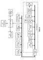
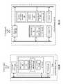
- FIG. 18is a schematic block diagram of another embodiment of an extended computing unit 14 that includes a connection module 220 , memory 222 , and hardware 224 .
- the memory 222may store an operating system (OS) extension 29 , one or more user applications 41 , one or more exclusive EXT user applications 226 , and an exclusive EXT operating system 228 .
- the one or more exclusive extended computing unit user applicationsincludes a voice over internet application, an internet radio application, an internet television application, an internet video playback application, and/or an entertainment device control application.
- connection module 220e.g., the EXT portion of connection 110 in FIGS. 7-17
- the hardware 224is operable to execute the extended computing unit exclusive operating system 226 from memory 222 , which may include EXT main memory, EXT RAM, EXT hard disk and/or flash memory.
- the exclusive EXT operation system 226may be conventional operating system, may be similar to the core operating system stored in the HH computing unit, or a custom operating system.
- the hardware 224While executing the exclusive EXT operating system, the hardware 224 is operable to detect a request for activation of an extended computing unit exclusive user application 226 . In this instance, the hardware 224 executes a least a portion of the extended computing unit exclusive user application. For example, when the HH computing unit 12 is not docked to the EXT computing unit 12 , the EXT computing unit 12 can support non-mobile functions such as a VoIP telephone, internet radio, internet TV, etc.
- the hardware 224may include one or more of: a processing module, a memory controller, an input/output controller, an input/output interface module, a peripheral component interface module, a graphics processing unit, and a graphics card interface module.
- Various embodiments of the hardware 224were previously described with reference to FIGS. 7-17 . Note that the hardware 224 and the memory 222 may be implemented on an integrated circuit 225 .
- FIG. 19is a schematic block diagram of another embodiment of an extended computing unit 14 that includes a connection module 220 , 1st memory 230 , 2nd memory 232 , 1st hardware 234 , and 2nd hardware 236 .
- the 1st memory 230may store the one or more exclusive EXT user applications 226 and the exclusive EXT operating system 228 and the 2nd memory 232 may store the operating system (OS) extension 29 and one or more user applications 41 .
- the 1st hardware 234may be a processing module coupled to the memory 232 and the 2nd hardware 236 may be the EXT hardware 25 .
- the 1st memory 230may store one or more exclusive extended computing unit system applications 226 .
- connection module 220e.g., the EXT portion of connection 110 in FIGS. 7-17
- the 1st hardware 234is operable to execute the extended computing unit exclusive operating system 226 from 1st memory 230 .
- the 2nd hardware 236 and the 2nd memory 232are inactive, or idle.
- the 1st hardware 234While executing the exclusive EXT operating system, the 1st hardware 234 is operable to detect a request for activation of an extended computing unit exclusive user application 226 . In this instance, the 1st hardware 234 executes a least a portion of the extended computing unit exclusive user application. For example, when the HH computing unit 12 is not docked to the EXT computing unit 12 , the EXT computing unit 12 can support non-mobile functions such as a VoIP telephone, internet radio, internet TV, etc.
- FIG. 20is a schematic block diagram of another embodiment of a computing device 10 that includes a handheld computing unit 12 docked, or quasi-docked, with an extended computing unit 14 .
- the computing device 10includes an application block, an application programming interfaces (API) block, operating system block (OS), and a hardware block (HW).
- the application blockincludes the EXT only applications 230 and the computer level applications 39 , which include the applications 41 on the HH computing unit 12 and the applications 43 on the EXT computing unit 14 .
- the hardware blockincludes the core hardware 23 on the handheld (HH) computing unit 12 and hardware 224 of the EXT computing unit 14 .
- the hardware of the HH computing unit 12may include one or more of: a radio frequency (RF) section, a baseband processing module, a hard disk and/or flash memory, main memory, a processing module, RAM, ROM, clock circuitry, an audio IO interface, a video IO interface, a data IO interface, and may further include a memory controller.
- RFradio frequency
- the hardware 224 of the EXT computing unit 14may include one or more of: a hard disk and/or flash memory, main memory, a co-processing module, RAM, ROM, slave clock circuitry, an audio IO interface, a video IO interface, a data IO interface, and may further include a memory controller.
- the hardware of the HH computing unit 12is the core hardware of the computing device 10 and the hardware 224 of the EXT computing unit 14 provides an extension of the HH hardware 23 .
- the processing module of the HH computing unit 12may use the processing module of the EXT computing unit 14 as a co-processor, as an auxiliary processor, as part of a multiple-processor core, or not use it at all.
- the HH computing unit 12may use the main memory of the EXT computing unit 14 as an extension of its main memory, as an auxiliary main memory (e.g., use as a backup copy), as a second layer of cache (e.g., L1 or L2 cache), or not use it at all.
- the exclusive EXT hardware 234enables the EXT computing unit 14 to support exclusive EXT applications 230 .
- the operating system blockincludes the EXT only OS 226 and the computer level operating system 27 , which includes the core operating system 29 stored in memory of the HH computing device 12 and the operating system extension 31 stored on the EXT computing unit 14 .
- the core operating system 29provides the primary operating system for the computing device 10 and the EXT operating system 31 augments the primary operating system for further functionality when the HH computing unit 12 is docked to the EXT computing unit 14 .
- the exclusive EXT operating system 226provides the functions as previously described with reference to FIGS. 18 and 19 .
- the API blockincludes the exclusive EXT API 228 and the computer level API 33 , which includes APIs 35 that are stored on the HH computing unit 12 and APIs 37 that are stored on the EXT computing unit 14 .
- applications blockincludes the exclusive EXT applications 230 and the computer level applications 39 , which include applications 41 that are stored on the HH computing unit 12 and applications 43 stored on the EXT computing unit 14 .
- FIG. 21is a schematic block diagram of another embodiment of a computing device 10 where the handheld computing unit 12 is not docked to an extended computing unit 14 .
- HH computing unit 12functions as a stand-alone mobile device while the EXT computing unit 14 is substantially non-operational for the extension applications 42 , the extension operating system 31 , and the extension APIs 37 , but is operational for the exclusive EXT applications 230 , the exclusive EXT APIs 228 , and the exclusive EXT operating system 226 .
- the architecture of the HH computing unit 12includes vertical functional coupling of the hardware 23 , the operating system 29 , the API 35 , and the applications 41 .
- the EXT computing unit 14does not include vertical functional coupling for the extension blocks since each of the blocks (e.g., hardware 25 , operating system 31 , API 37 , and applications 43 ) are extensions of the corresponding blocks of the HH computing unit 12 .
- the EXT computing unit 14does include vertical functional coupling for the exclusive EXT functions as previously described.
- FIG. 22is a schematic block diagram of another embodiment of a computing device 10 that includes a handheld computing unit 12 docked, or quasi-docked, with an extended computing unit 14 .
- the computing device 10includes an application block, an application programming interfaces (API) block, operating system block (OS), and a hardware block (HW).
- the application blockincludes the EXT only applications 230 and the computer level applications 39 , which include the applications 41 on the HH computing unit 12 and the applications 43 on the EXT computing unit 14 .
- the hardware blockincludes the exclusive EXT hardware 234 and the computer level hardware 21 , which includes the core hardware 23 on the handheld (HH) computing unit 12 and hardware 25 of the EXT computing unit 14 .
- the hardware of the HH computing unit 12may include one or more of: a radio frequency (RF) section, a baseband processing module, a hard disk and/or flash memory, main memory, a processing module, RAM, ROM, clock circuitry, an audio IO interface, a video IO interface, a data IO interface, and may further include a memory controller.
- RFradio frequency
- the hardware 234 of the EXT computing unit 14may include one or more of: a hard disk and/or flash memory, main memory, a co-processing module, RAM, ROM, slave clock circuitry, an audio IO interface, a video IO interface, a data IO interface, and may further include a memory controller.
- the hardware of the HH computing unit 12is the core hardware of the computing device 10 and the hardware 25 of the EXT computing unit 14 provides an extension of the HH hardware 23 .
- the processing module of the HH computing unit 12may use the processing module of the EXT computing unit 14 as a co-processor, as an auxiliary processor, as part of a multiple-processor core, or not use it at all.
- the HH computing unit 12may use the main memory of the EXT computing unit 14 as an extension of its main memory, as an auxiliary main memory (e.g., use as a backup copy), as a second layer of cache (e.g., L1 or L2 cache), or not use it at all.
- the exclusive EXT hardware 234enables the EXT computing unit 14 to support exclusive EXT applications 230 .
- the operating system blockincludes the EXT only OS 226 and the computer level operating system 27 , which includes the core operating system 29 stored in memory of the HH computing device 12 and the operating system extension 31 stored on the EXT computing unit 14 .
- the core operating system 29provides the primary operating system for the computing device 10 and the EXT operating system 31 augments the primary operating system for further functionality when the HH computing unit 12 is docked to the EXT computing unit 14 .
- the exclusive EXT operating system 226provides the functions as previously described with reference to FIGS. 18 and 19 .
- the API blockincludes the exclusive EXT API 228 and the computer level API 33 , which includes APIs 35 that are stored on the HH computing unit 12 and APIs 37 that are stored on the EXT computing unit 14 .
- applications blockincludes the exclusive EXT applications 230 and the computer level applications 39 , which include applications 41 that are stored on the HH computing unit 12 and applications 43 stored on the EXT computing unit 14 .
- FIG. 23is a schematic block diagram of another embodiment of a computing device 10 where the handheld computing unit 12 is not docked to an extended computing unit 14 .
- HH computing unit 12functions as a stand-alone mobile device while the EXT computing unit 14 is substantially non-operational for the extension applications 42 , the extension operating system 31 , and the extension APIs 37 , but is operational for the exclusive EXT applications 230 , the exclusive EXT APIs 228 , and the exclusive EXT operating system 226 .
- the architecture of the HH computing unit 12includes vertical functional coupling of the hardware 23 , the operating system 29 , the API 35 , and the applications 41 .
- the EXT computing unit 14does not include vertical functional coupling for the extension blocks since each of the blocks (e.g., hardware 25 , operating system 31 , API 37 , and applications 43 ) are extensions of the corresponding blocks of the HH computing unit 12 .
- the EXT computing unit 14does include vertical functional coupling for the exclusive EXT functions as previously described.
- FIG. 24is a schematic block diagram of another embodiment of an extended computing unit 14 that includes the hardware 224 , the memory 222 , and the connection module 220 . Note that the memory 222 and the hardware 224 may be implemented on an integrated circuit 225 .
- the memory 222stores one or more computer-level user applications 41 and an operating system extension of a computer-level operating system 29 .
- the memory 222may further store a computer-level system application 240 .
- the connection module 230is coupled to a handheld computing unit 12
- the hardware 224is operable, in combination with hardware of the handheld computing unit, to execute at least one of: at least a portion of a computer-level user application of the one or more computer-level user applications, and at least a portion of the operating system extension.
- the hardwareis operable, in combination with hardware of the handheld computing unit, to execute at least a portion of a computer-level system application 240 .
- the terms “substantially” and “approximately”provides an industry-accepted tolerance for its corresponding term and/or relativity between items. Such an industry-accepted tolerance ranges from less than one percent to fifty percent and corresponds to, but is not limited to, component values, integrated circuit process variations, temperature variations, rise and fall times, and/or thermal noise. Such relativity between items ranges from a difference of a few percent to magnitude differences.
- the term(s) “coupled to” and/or “coupling”includes direct coupling between items and/or indirect coupling between items via an intervening item (e.g., an item includes, but is not limited to, a component, an element, a circuit, and/or a module) where, for indirect coupling, the intervening item does not modify the information of a signal but may adjust its current level, voltage level, and/or power level.
- an intervening iteme.g., an item includes, but is not limited to, a component, an element, a circuit, and/or a module
- inferred couplingi.e., where one element is coupled to another element by inference
- inferred couplingincludes direct and indirect coupling between two items in the same manner as “coupled to”.
- the term “operable to”indicates that an item includes one or more of power connections, input(s), output(s), etc., to perform, when activated, one or more its corresponding functions and may further include inferred coupling to one or more other items.
- the term “associated with”,includes direct and/or indirect coupling of separate items and/or one item being embedded within another item.
- the term “compares favorably”,indicates that a comparison between two or more items, signals, etc., provides a desired relationship. For example, when the desired relationship is that signal 1 has a greater magnitude than signal 2 , a favorable comparison may be achieved when the magnitude of signal 1 is greater than that of signal 2 or when the magnitude of signal 2 is less than that of signal 1 .
Landscapes
- Engineering & Computer Science (AREA)
- Theoretical Computer Science (AREA)
- Computer Hardware Design (AREA)
- Human Computer Interaction (AREA)
- Physics & Mathematics (AREA)
- General Engineering & Computer Science (AREA)
- General Physics & Mathematics (AREA)
- Stored Programmes (AREA)
- Telephone Function (AREA)
Abstract
Description
Claims (18)
Priority Applications (1)
| Application Number | Priority Date | Filing Date | Title |
|---|---|---|---|
| US12/326,971US7870321B2 (en) | 2008-02-06 | 2008-12-03 | Extended computing unit with stand-alone application |
Applications Claiming Priority (2)
| Application Number | Priority Date | Filing Date | Title |
|---|---|---|---|
| US12/026,681US20090197641A1 (en) | 2008-02-06 | 2008-02-06 | Computing device with handheld and extended computing units |
| US12/326,971US7870321B2 (en) | 2008-02-06 | 2008-12-03 | Extended computing unit with stand-alone application |
Related Parent Applications (1)
| Application Number | Title | Priority Date | Filing Date |
|---|---|---|---|
| US12/026,681Continuation-In-PartUS20090197641A1 (en) | 2007-01-31 | 2008-02-06 | Computing device with handheld and extended computing units |
Publications (2)
| Publication Number | Publication Date |
|---|---|
| US20090198851A1 US20090198851A1 (en) | 2009-08-06 |
| US7870321B2true US7870321B2 (en) | 2011-01-11 |
Family
ID=40932763
Family Applications (1)
| Application Number | Title | Priority Date | Filing Date |
|---|---|---|---|
| US12/326,971Expired - Fee RelatedUS7870321B2 (en) | 2008-02-06 | 2008-12-03 | Extended computing unit with stand-alone application |
Country Status (1)
| Country | Link |
|---|---|
| US (1) | US7870321B2 (en) |
Cited By (73)
| Publication number | Priority date | Publication date | Assignee | Title |
|---|---|---|---|---|
| US20120143944A1 (en)* | 2010-10-01 | 2012-06-07 | Imerj, Llc | Integrated handset browser settings |
| US8532492B2 (en) | 2009-02-03 | 2013-09-10 | Corning Cable Systems Llc | Optical fiber-based distributed antenna systems, components, and related methods for calibration thereof |
| US8548330B2 (en) | 2009-07-31 | 2013-10-01 | Corning Cable Systems Llc | Sectorization in distributed antenna systems, and related components and methods |
| US8639121B2 (en) | 2009-11-13 | 2014-01-28 | Corning Cable Systems Llc | Radio-over-fiber (RoF) system for protocol-independent wired and/or wireless communication |
| US8644844B2 (en) | 2007-12-20 | 2014-02-04 | Corning Mobileaccess Ltd. | Extending outdoor location based services and applications into enclosed areas |
| US8718478B2 (en) | 2007-10-12 | 2014-05-06 | Corning Cable Systems Llc | Hybrid wireless/wired RoF transponder and hybrid RoF communication system using same |
| US8831428B2 (en) | 2010-02-15 | 2014-09-09 | Corning Optical Communications LLC | Dynamic cell bonding (DCB) for radio-over-fiber (RoF)-based networks and communication systems and related methods |
| US8867919B2 (en) | 2007-07-24 | 2014-10-21 | Corning Cable Systems Llc | Multi-port accumulator for radio-over-fiber (RoF) wireless picocellular systems |
| US8873585B2 (en) | 2006-12-19 | 2014-10-28 | Corning Optical Communications Wireless Ltd | Distributed antenna system for MIMO technologies |
| US8897215B2 (en) | 2009-02-08 | 2014-11-25 | Corning Optical Communications Wireless Ltd | Communication system using cables carrying ethernet signals |
| US8983301B2 (en) | 2010-03-31 | 2015-03-17 | Corning Optical Communications LLC | Localization services in optical fiber-based distributed communications components and systems, and related methods |
| US9037143B2 (en) | 2010-08-16 | 2015-05-19 | Corning Optical Communications LLC | Remote antenna clusters and related systems, components, and methods supporting digital data signal propagation between remote antenna units |
| US9042732B2 (en) | 2010-05-02 | 2015-05-26 | Corning Optical Communications LLC | Providing digital data services in optical fiber-based distributed radio frequency (RF) communication systems, and related components and methods |
| US9158864B2 (en) | 2012-12-21 | 2015-10-13 | Corning Optical Communications Wireless Ltd | Systems, methods, and devices for documenting a location of installed equipment |
| US9178635B2 (en) | 2014-01-03 | 2015-11-03 | Corning Optical Communications Wireless Ltd | Separation of communication signal sub-bands in distributed antenna systems (DASs) to reduce interference |
| US9184843B2 (en) | 2011-04-29 | 2015-11-10 | Corning Optical Communications LLC | Determining propagation delay of communications in distributed antenna systems, and related components, systems, and methods |
| US9184960B1 (en) | 2014-09-25 | 2015-11-10 | Corning Optical Communications Wireless Ltd | Frequency shifting a communications signal(s) in a multi-frequency distributed antenna system (DAS) to avoid or reduce frequency interference |
| US9185674B2 (en) | 2010-08-09 | 2015-11-10 | Corning Cable Systems Llc | Apparatuses, systems, and methods for determining location of a mobile device(s) in a distributed antenna system(s) |
| US9240835B2 (en) | 2011-04-29 | 2016-01-19 | Corning Optical Communications LLC | Systems, methods, and devices for increasing radio frequency (RF) power in distributed antenna systems |
| US9247543B2 (en) | 2013-07-23 | 2016-01-26 | Corning Optical Communications Wireless Ltd | Monitoring non-supported wireless spectrum within coverage areas of distributed antenna systems (DASs) |
| US9258052B2 (en) | 2012-03-30 | 2016-02-09 | Corning Optical Communications LLC | Reducing location-dependent interference in distributed antenna systems operating in multiple-input, multiple-output (MIMO) configuration, and related components, systems, and methods |
| US9312938B2 (en) | 2007-02-19 | 2016-04-12 | Corning Optical Communications Wireless Ltd | Method and system for improving uplink performance |
| US9325429B2 (en) | 2011-02-21 | 2016-04-26 | Corning Optical Communications LLC | Providing digital data services as electrical signals and radio-frequency (RF) communications over optical fiber in distributed communications systems, and related components and methods |
| US9324234B2 (en) | 2010-10-01 | 2016-04-26 | Autoconnect Holdings Llc | Vehicle comprising multi-operating system |
| US9338823B2 (en) | 2012-03-23 | 2016-05-10 | Corning Optical Communications Wireless Ltd | Radio-frequency integrated circuit (RFIC) chip(s) for providing distributed antenna system functionalities, and related components, systems, and methods |
| US9357551B2 (en) | 2014-05-30 | 2016-05-31 | Corning Optical Communications Wireless Ltd | Systems and methods for simultaneous sampling of serial digital data streams from multiple analog-to-digital converters (ADCS), including in distributed antenna systems |
| US9385810B2 (en) | 2013-09-30 | 2016-07-05 | Corning Optical Communications Wireless Ltd | Connection mapping in distributed communication systems |
| US9419712B2 (en) | 2010-10-13 | 2016-08-16 | Ccs Technology, Inc. | Power management for remote antenna units in distributed antenna systems |
| US9420542B2 (en) | 2014-09-25 | 2016-08-16 | Corning Optical Communications Wireless Ltd | System-wide uplink band gain control in a distributed antenna system (DAS), based on per band gain control of remote uplink paths in remote units |
| US9455784B2 (en) | 2012-10-31 | 2016-09-27 | Corning Optical Communications Wireless Ltd | Deployable wireless infrastructures and methods of deploying wireless infrastructures |
| US9497706B2 (en) | 2013-02-20 | 2016-11-15 | Corning Optical Communications Wireless Ltd | Power management in distributed antenna systems (DASs), and related components, systems, and methods |
| US9509133B2 (en) | 2014-06-27 | 2016-11-29 | Corning Optical Communications Wireless Ltd | Protection of distributed antenna systems |
| US9525488B2 (en) | 2010-05-02 | 2016-12-20 | Corning Optical Communications LLC | Digital data services and/or power distribution in optical fiber-based distributed communications systems providing digital data and radio frequency (RF) communications services, and related components and methods |
| US9525472B2 (en) | 2014-07-30 | 2016-12-20 | Corning Incorporated | Reducing location-dependent destructive interference in distributed antenna systems (DASS) operating in multiple-input, multiple-output (MIMO) configuration, and related components, systems, and methods |
| US9531452B2 (en) | 2012-11-29 | 2016-12-27 | Corning Optical Communications LLC | Hybrid intra-cell / inter-cell remote unit antenna bonding in multiple-input, multiple-output (MIMO) distributed antenna systems (DASs) |
| US9549301B2 (en) | 2007-12-17 | 2017-01-17 | Corning Optical Communications Wireless Ltd | Method and system for real time control of an active antenna over a distributed antenna system |
| US9590733B2 (en) | 2009-07-24 | 2017-03-07 | Corning Optical Communications LLC | Location tracking using fiber optic array cables and related systems and methods |
| US9602210B2 (en) | 2014-09-24 | 2017-03-21 | Corning Optical Communications Wireless Ltd | Flexible head-end chassis supporting automatic identification and interconnection of radio interface modules and optical interface modules in an optical fiber-based distributed antenna system (DAS) |
| US9621293B2 (en) | 2012-08-07 | 2017-04-11 | Corning Optical Communications Wireless Ltd | Distribution of time-division multiplexed (TDM) management services in a distributed antenna system, and related components, systems, and methods |
| US9648580B1 (en) | 2016-03-23 | 2017-05-09 | Corning Optical Communications Wireless Ltd | Identifying remote units in a wireless distribution system (WDS) based on assigned unique temporal delay patterns |
| US9647758B2 (en) | 2012-11-30 | 2017-05-09 | Corning Optical Communications Wireless Ltd | Cabling connectivity monitoring and verification |
| US9653861B2 (en) | 2014-09-17 | 2017-05-16 | Corning Optical Communications Wireless Ltd | Interconnection of hardware components |
| US9661781B2 (en) | 2013-07-31 | 2017-05-23 | Corning Optical Communications Wireless Ltd | Remote units for distributed communication systems and related installation methods and apparatuses |
| US9673904B2 (en) | 2009-02-03 | 2017-06-06 | Corning Optical Communications LLC | Optical fiber-based distributed antenna systems, components, and related methods for calibration thereof |
| US9681313B2 (en) | 2015-04-15 | 2017-06-13 | Corning Optical Communications Wireless Ltd | Optimizing remote antenna unit performance using an alternative data channel |
| US9685782B2 (en) | 2010-11-24 | 2017-06-20 | Corning Optical Communications LLC | Power distribution module(s) capable of hot connection and/or disconnection for distributed antenna systems, and related power units, components, and methods |
| US9684060B2 (en) | 2012-05-29 | 2017-06-20 | CorningOptical Communications LLC | Ultrasound-based localization of client devices with inertial navigation supplement in distributed communication systems and related devices and methods |
| US9699723B2 (en) | 2010-10-13 | 2017-07-04 | Ccs Technology, Inc. | Local power management for remote antenna units in distributed antenna systems |
| US9715157B2 (en) | 2013-06-12 | 2017-07-25 | Corning Optical Communications Wireless Ltd | Voltage controlled optical directional coupler |
| US9729267B2 (en) | 2014-12-11 | 2017-08-08 | Corning Optical Communications Wireless Ltd | Multiplexing two separate optical links with the same wavelength using asymmetric combining and splitting |
| US9730228B2 (en) | 2014-08-29 | 2017-08-08 | Corning Optical Communications Wireless Ltd | Individualized gain control of remote uplink band paths in a remote unit in a distributed antenna system (DAS), based on combined uplink power level in the remote unit |
| US9729251B2 (en) | 2012-07-31 | 2017-08-08 | Corning Optical Communications LLC | Cooling system control in distributed antenna systems |
| US9775123B2 (en) | 2014-03-28 | 2017-09-26 | Corning Optical Communications Wireless Ltd. | Individualized gain control of uplink paths in remote units in a distributed antenna system (DAS) based on individual remote unit contribution to combined uplink power |
| US9781553B2 (en) | 2012-04-24 | 2017-10-03 | Corning Optical Communications LLC | Location based services in a distributed communication system, and related components and methods |
| US9785175B2 (en) | 2015-03-27 | 2017-10-10 | Corning Optical Communications Wireless, Ltd. | Combining power from electrically isolated power paths for powering remote units in a distributed antenna system(s) (DASs) |
| US9800340B2 (en) | 2013-10-28 | 2017-10-24 | Corning Optical Communications Wireless Ltd | Unified optical fiber-based distributed antenna systems (DASs) for supporting small cell communications deployment from multiple small cell service providers, and related devices and methods |
| US9807700B2 (en) | 2015-02-19 | 2017-10-31 | Corning Optical Communications Wireless Ltd | Offsetting unwanted downlink interference signals in an uplink path in a distributed antenna system (DAS) |
| US9813229B2 (en) | 2007-10-22 | 2017-11-07 | Corning Optical Communications Wireless Ltd | Communication system using low bandwidth wires |
| US9948349B2 (en) | 2015-07-17 | 2018-04-17 | Corning Optical Communications Wireless Ltd | IOT automation and data collection system |
| US9974074B2 (en) | 2013-06-12 | 2018-05-15 | Corning Optical Communications Wireless Ltd | Time-division duplexing (TDD) in distributed communications systems, including distributed antenna systems (DASs) |
| US10096909B2 (en) | 2014-11-03 | 2018-10-09 | Corning Optical Communications Wireless Ltd. | Multi-band monopole planar antennas configured to facilitate improved radio frequency (RF) isolation in multiple-input multiple-output (MIMO) antenna arrangement |
| US10110308B2 (en) | 2014-12-18 | 2018-10-23 | Corning Optical Communications Wireless Ltd | Digital interface modules (DIMs) for flexibly distributing digital and/or analog communications signals in wide-area analog distributed antenna systems (DASs) |
| US10128951B2 (en) | 2009-02-03 | 2018-11-13 | Corning Optical Communications LLC | Optical fiber-based distributed antenna systems, components, and related methods for monitoring and configuring thereof |
| US10136200B2 (en) | 2012-04-25 | 2018-11-20 | Corning Optical Communications LLC | Distributed antenna system architectures |
| US10135533B2 (en) | 2014-11-13 | 2018-11-20 | Corning Optical Communications Wireless Ltd | Analog distributed antenna systems (DASS) supporting distribution of digital communications signals interfaced from a digital signal source and analog radio frequency (RF) communications signals |
| US10187151B2 (en) | 2014-12-18 | 2019-01-22 | Corning Optical Communications Wireless Ltd | Digital-analog interface modules (DAIMs) for flexibly distributing digital and/or analog communications signals in wide-area analog distributed antenna systems (DASs) |
| US10236924B2 (en) | 2016-03-31 | 2019-03-19 | Corning Optical Communications Wireless Ltd | Reducing out-of-channel noise in a wireless distribution system (WDS) |
| US10257056B2 (en) | 2012-11-28 | 2019-04-09 | Corning Optical Communications LLC | Power management for distributed communication systems, and related components, systems, and methods |
| US10455497B2 (en) | 2013-11-26 | 2019-10-22 | Corning Optical Communications LLC | Selective activation of communications services on power-up of a remote unit(s) in a wireless communication system (WCS) based on power consumption |
| US10560214B2 (en) | 2015-09-28 | 2020-02-11 | Corning Optical Communications LLC | Downlink and uplink communication path switching in a time-division duplex (TDD) distributed antenna system (DAS) |
| US10659163B2 (en) | 2014-09-25 | 2020-05-19 | Corning Optical Communications LLC | Supporting analog remote antenna units (RAUs) in digital distributed antenna systems (DASs) using analog RAU digital adaptors |
| US10992484B2 (en) | 2013-08-28 | 2021-04-27 | Corning Optical Communications LLC | Power management for distributed communication systems, and related components, systems, and methods |
| US11296504B2 (en) | 2010-11-24 | 2022-04-05 | Corning Optical Communications LLC | Power distribution module(s) capable of hot connection and/or disconnection for wireless communication systems, and related power units, components, and methods |
Families Citing this family (2)
| Publication number | Priority date | Publication date | Assignee | Title |
|---|---|---|---|---|
| US8442509B2 (en)* | 2009-01-30 | 2013-05-14 | Cassis International Pte. Ltd. | System and method for managing a wireless device from removable media with processing capability |
| GB2479996A (en)* | 2010-04-26 | 2011-11-02 | Hu-Do Ltd | Mobile computing device operating in conjunction with companion computing device to generate a user environment. |
Citations (22)
| Publication number | Priority date | Publication date | Assignee | Title |
|---|---|---|---|---|
| US5579489A (en)* | 1993-02-10 | 1996-11-26 | Elonex I.P. Holdings, Ltd. | Hand-held portable computer having capability for external expansion of an internal bus |
| US6075939A (en)* | 1997-09-27 | 2000-06-13 | Lynx Real-Trime Systems, Inc. | Tightly coupled, scalable module based micro-kernel operating system architecture |
| US6374353B1 (en)* | 1998-03-16 | 2002-04-16 | Mitsubishi Denki Kabushiki Kaisha | Information processing apparatus method of booting information processing apparatus at a high speed |
| US6493783B1 (en)* | 1999-04-13 | 2002-12-10 | International Business Machines Corporation | Undocking method for multilayer-dock structure constituted by docking plurality of expansion units to a portable PC |
| US6571308B1 (en)* | 2000-01-31 | 2003-05-27 | Koninklijke Philips Electronics N.V. | Bridging a host bus to an external bus using a host-bus-to-processor protocol translator |
| US6584533B1 (en)* | 1999-11-10 | 2003-06-24 | Samsung Electronics Co., Ltd. | Docking system for a computer |
| US20030172218A1 (en)* | 2002-03-08 | 2003-09-11 | Bryan Scott | Systems, devices, and methods for transferring data between an intelligent docking station and a handheld personal computer |
| US6631469B1 (en)* | 2000-07-17 | 2003-10-07 | Intel Corporation | Method and apparatus for periodic low power data exchange |
| US6735663B2 (en)* | 2000-12-18 | 2004-05-11 | Dell Products L.P. | Combination personal data assistant and personal computing device |
| US6842795B2 (en)* | 2002-06-10 | 2005-01-11 | Siemens Communications, Inc. | Methods and apparatus for shifting focus between multiple devices |
| US20050050135A1 (en)* | 2003-08-25 | 2005-03-03 | Josef Hallermeier | Handheld digital multimedia workstation and method |
| US20050185364A1 (en)* | 2004-01-05 | 2005-08-25 | Jory Bell | Docking station for mobile computing device |
| US20060010314A1 (en)* | 2004-07-07 | 2006-01-12 | Yongyong Xu | Methods and systems for running multiple operating systems in a single mobile device |
| US7010634B2 (en)* | 1999-12-23 | 2006-03-07 | Intel Corporation | Notebook computer with independently functional, dockable core computer |
| US7113497B2 (en)* | 2002-05-08 | 2006-09-26 | Lenovo (Singapore) Pte. Ltd. | Bandwidth management in a wireless network |
| US7197584B2 (en)* | 2001-01-26 | 2007-03-27 | Dell Products L.P. | Removable personal digital assistant in a dual personal computer/personal digital assistant computer architecture |
| US20070074226A1 (en)* | 2005-09-28 | 2007-03-29 | Zimmer Vincent J | Systems and methods for device driver isolation |
| US7222207B2 (en)* | 2002-11-15 | 2007-05-22 | Microsoft Corporation | Portable computing device-integrated appliance |
| US7231481B2 (en)* | 2002-02-01 | 2007-06-12 | Bryan Scott | Intelligent docking station for a handheld personal computer |
| US20070180509A1 (en)* | 2005-12-07 | 2007-08-02 | Swartz Alon R | Practical platform for high risk applications |
| US20080028102A1 (en)* | 2000-06-20 | 2008-01-31 | Palmsource, Inc. | Data exchange between a handheld device and another computer system using an exchange manager via synchronization |
| US7343484B2 (en)* | 2002-03-28 | 2008-03-11 | O2Micro International Limited | Personal computer integrated with personal digital assistant |
- 2008
- 2008-12-03USUS12/326,971patent/US7870321B2/ennot_activeExpired - Fee Related
Patent Citations (23)
| Publication number | Priority date | Publication date | Assignee | Title |
|---|---|---|---|---|
| US5579489A (en)* | 1993-02-10 | 1996-11-26 | Elonex I.P. Holdings, Ltd. | Hand-held portable computer having capability for external expansion of an internal bus |
| US6075939A (en)* | 1997-09-27 | 2000-06-13 | Lynx Real-Trime Systems, Inc. | Tightly coupled, scalable module based micro-kernel operating system architecture |
| US6374353B1 (en)* | 1998-03-16 | 2002-04-16 | Mitsubishi Denki Kabushiki Kaisha | Information processing apparatus method of booting information processing apparatus at a high speed |
| US6493783B1 (en)* | 1999-04-13 | 2002-12-10 | International Business Machines Corporation | Undocking method for multilayer-dock structure constituted by docking plurality of expansion units to a portable PC |
| US6584533B1 (en)* | 1999-11-10 | 2003-06-24 | Samsung Electronics Co., Ltd. | Docking system for a computer |
| US7010634B2 (en)* | 1999-12-23 | 2006-03-07 | Intel Corporation | Notebook computer with independently functional, dockable core computer |
| US6571308B1 (en)* | 2000-01-31 | 2003-05-27 | Koninklijke Philips Electronics N.V. | Bridging a host bus to an external bus using a host-bus-to-processor protocol translator |
| US20080028102A1 (en)* | 2000-06-20 | 2008-01-31 | Palmsource, Inc. | Data exchange between a handheld device and another computer system using an exchange manager via synchronization |
| US6631469B1 (en)* | 2000-07-17 | 2003-10-07 | Intel Corporation | Method and apparatus for periodic low power data exchange |
| US7149837B2 (en)* | 2000-12-18 | 2006-12-12 | Dell Products L.P. | Method of operating combination personal data assistant and personal computing device |
| US6735663B2 (en)* | 2000-12-18 | 2004-05-11 | Dell Products L.P. | Combination personal data assistant and personal computing device |
| US7197584B2 (en)* | 2001-01-26 | 2007-03-27 | Dell Products L.P. | Removable personal digital assistant in a dual personal computer/personal digital assistant computer architecture |
| US7231481B2 (en)* | 2002-02-01 | 2007-06-12 | Bryan Scott | Intelligent docking station for a handheld personal computer |
| US20030172218A1 (en)* | 2002-03-08 | 2003-09-11 | Bryan Scott | Systems, devices, and methods for transferring data between an intelligent docking station and a handheld personal computer |
| US7343484B2 (en)* | 2002-03-28 | 2008-03-11 | O2Micro International Limited | Personal computer integrated with personal digital assistant |
| US7113497B2 (en)* | 2002-05-08 | 2006-09-26 | Lenovo (Singapore) Pte. Ltd. | Bandwidth management in a wireless network |
| US6842795B2 (en)* | 2002-06-10 | 2005-01-11 | Siemens Communications, Inc. | Methods and apparatus for shifting focus between multiple devices |
| US7222207B2 (en)* | 2002-11-15 | 2007-05-22 | Microsoft Corporation | Portable computing device-integrated appliance |
| US20050050135A1 (en)* | 2003-08-25 | 2005-03-03 | Josef Hallermeier | Handheld digital multimedia workstation and method |
| US20050185364A1 (en)* | 2004-01-05 | 2005-08-25 | Jory Bell | Docking station for mobile computing device |
| US20060010314A1 (en)* | 2004-07-07 | 2006-01-12 | Yongyong Xu | Methods and systems for running multiple operating systems in a single mobile device |
| US20070074226A1 (en)* | 2005-09-28 | 2007-03-29 | Zimmer Vincent J | Systems and methods for device driver isolation |
| US20070180509A1 (en)* | 2005-12-07 | 2007-08-02 | Swartz Alon R | Practical platform for high risk applications |
Cited By (141)
| Publication number | Priority date | Publication date | Assignee | Title |
|---|---|---|---|---|
| US8873585B2 (en) | 2006-12-19 | 2014-10-28 | Corning Optical Communications Wireless Ltd | Distributed antenna system for MIMO technologies |
| US9130613B2 (en) | 2006-12-19 | 2015-09-08 | Corning Optical Communications Wireless Ltd | Distributed antenna system for MIMO technologies |
| US9312938B2 (en) | 2007-02-19 | 2016-04-12 | Corning Optical Communications Wireless Ltd | Method and system for improving uplink performance |
| US8867919B2 (en) | 2007-07-24 | 2014-10-21 | Corning Cable Systems Llc | Multi-port accumulator for radio-over-fiber (RoF) wireless picocellular systems |
| US8718478B2 (en) | 2007-10-12 | 2014-05-06 | Corning Cable Systems Llc | Hybrid wireless/wired RoF transponder and hybrid RoF communication system using same |
| US9813229B2 (en) | 2007-10-22 | 2017-11-07 | Corning Optical Communications Wireless Ltd | Communication system using low bandwidth wires |
| US9549301B2 (en) | 2007-12-17 | 2017-01-17 | Corning Optical Communications Wireless Ltd | Method and system for real time control of an active antenna over a distributed antenna system |
| US8644844B2 (en) | 2007-12-20 | 2014-02-04 | Corning Mobileaccess Ltd. | Extending outdoor location based services and applications into enclosed areas |
| US9112611B2 (en) | 2009-02-03 | 2015-08-18 | Corning Optical Communications LLC | Optical fiber-based distributed antenna systems, components, and related methods for calibration thereof |
| US9900097B2 (en) | 2009-02-03 | 2018-02-20 | Corning Optical Communications LLC | Optical fiber-based distributed antenna systems, components, and related methods for calibration thereof |
| US10128951B2 (en) | 2009-02-03 | 2018-11-13 | Corning Optical Communications LLC | Optical fiber-based distributed antenna systems, components, and related methods for monitoring and configuring thereof |
| US9673904B2 (en) | 2009-02-03 | 2017-06-06 | Corning Optical Communications LLC | Optical fiber-based distributed antenna systems, components, and related methods for calibration thereof |
| US10153841B2 (en) | 2009-02-03 | 2018-12-11 | Corning Optical Communications LLC | Optical fiber-based distributed antenna systems, components, and related methods for calibration thereof |
| US8532492B2 (en) | 2009-02-03 | 2013-09-10 | Corning Cable Systems Llc | Optical fiber-based distributed antenna systems, components, and related methods for calibration thereof |
| US8897215B2 (en) | 2009-02-08 | 2014-11-25 | Corning Optical Communications Wireless Ltd | Communication system using cables carrying ethernet signals |
| US10070258B2 (en) | 2009-07-24 | 2018-09-04 | Corning Optical Communications LLC | Location tracking using fiber optic array cables and related systems and methods |
| US9590733B2 (en) | 2009-07-24 | 2017-03-07 | Corning Optical Communications LLC | Location tracking using fiber optic array cables and related systems and methods |
| US8548330B2 (en) | 2009-07-31 | 2013-10-01 | Corning Cable Systems Llc | Sectorization in distributed antenna systems, and related components and methods |
| US9485022B2 (en) | 2009-11-13 | 2016-11-01 | Corning Optical Communications LLC | Radio-over-fiber (ROF) system for protocol-independent wired and/or wireless communication |
| US9729238B2 (en) | 2009-11-13 | 2017-08-08 | Corning Optical Communications LLC | Radio-over-fiber (ROF) system for protocol-independent wired and/or wireless communication |
| US8639121B2 (en) | 2009-11-13 | 2014-01-28 | Corning Cable Systems Llc | Radio-over-fiber (RoF) system for protocol-independent wired and/or wireless communication |
| US9219879B2 (en) | 2009-11-13 | 2015-12-22 | Corning Optical Communications LLC | Radio-over-fiber (ROF) system for protocol-independent wired and/or wireless communication |
| US9319138B2 (en) | 2010-02-15 | 2016-04-19 | Corning Optical Communications LLC | Dynamic cell bonding (DCB) for radio-over-fiber (RoF)-based networks and communication systems and related methods |
| US8831428B2 (en) | 2010-02-15 | 2014-09-09 | Corning Optical Communications LLC | Dynamic cell bonding (DCB) for radio-over-fiber (RoF)-based networks and communication systems and related methods |
| US9967032B2 (en) | 2010-03-31 | 2018-05-08 | Corning Optical Communications LLC | Localization services in optical fiber-based distributed communications components and systems, and related methods |
| US8983301B2 (en) | 2010-03-31 | 2015-03-17 | Corning Optical Communications LLC | Localization services in optical fiber-based distributed communications components and systems, and related methods |
| US9853732B2 (en) | 2010-05-02 | 2017-12-26 | Corning Optical Communications LLC | Digital data services and/or power distribution in optical fiber-based distributed communications systems providing digital data and radio frequency (RF) communications services, and related components and methods |
| US9525488B2 (en) | 2010-05-02 | 2016-12-20 | Corning Optical Communications LLC | Digital data services and/or power distribution in optical fiber-based distributed communications systems providing digital data and radio frequency (RF) communications services, and related components and methods |
| US9270374B2 (en) | 2010-05-02 | 2016-02-23 | Corning Optical Communications LLC | Providing digital data services in optical fiber-based distributed radio frequency (RF) communications systems, and related components and methods |
| US9042732B2 (en) | 2010-05-02 | 2015-05-26 | Corning Optical Communications LLC | Providing digital data services in optical fiber-based distributed radio frequency (RF) communication systems, and related components and methods |
| US9185674B2 (en) | 2010-08-09 | 2015-11-10 | Corning Cable Systems Llc | Apparatuses, systems, and methods for determining location of a mobile device(s) in a distributed antenna system(s) |
| US9913094B2 (en) | 2010-08-09 | 2018-03-06 | Corning Optical Communications LLC | Apparatuses, systems, and methods for determining location of a mobile device(s) in a distributed antenna system(s) |
| US10959047B2 (en) | 2010-08-09 | 2021-03-23 | Corning Optical Communications LLC | Apparatuses, systems, and methods for determining location of a mobile device(s) in a distributed antenna system(s) |
| US12160789B2 (en) | 2010-08-09 | 2024-12-03 | Corning Optical Communications LLC | Apparatuses, systems, and methods for determining location of a mobile device(s) in a distributed antenna system(s) |
| US10448205B2 (en) | 2010-08-09 | 2019-10-15 | Corning Optical Communications LLC | Apparatuses, systems, and methods for determining location of a mobile device(s) in a distributed antenna system(s) |
| US11653175B2 (en) | 2010-08-09 | 2023-05-16 | Corning Optical Communications LLC | Apparatuses, systems, and methods for determining location of a mobile device(s) in a distributed antenna system(s) |
| US10014944B2 (en) | 2010-08-16 | 2018-07-03 | Corning Optical Communications LLC | Remote antenna clusters and related systems, components, and methods supporting digital data signal propagation between remote antenna units |
| US9037143B2 (en) | 2010-08-16 | 2015-05-19 | Corning Optical Communications LLC | Remote antenna clusters and related systems, components, and methods supporting digital data signal propagation between remote antenna units |
| US9324234B2 (en) | 2010-10-01 | 2016-04-26 | Autoconnect Holdings Llc | Vehicle comprising multi-operating system |
| US20120143944A1 (en)* | 2010-10-01 | 2012-06-07 | Imerj, Llc | Integrated handset browser settings |
| US8819180B2 (en)* | 2010-10-01 | 2014-08-26 | Z124 | Integrated handset browser settings |
| US11671914B2 (en) | 2010-10-13 | 2023-06-06 | Corning Optical Communications LLC | Power management for remote antenna units in distributed antenna systems |
| US9699723B2 (en) | 2010-10-13 | 2017-07-04 | Ccs Technology, Inc. | Local power management for remote antenna units in distributed antenna systems |
| US9419712B2 (en) | 2010-10-13 | 2016-08-16 | Ccs Technology, Inc. | Power management for remote antenna units in distributed antenna systems |
| US10045288B2 (en) | 2010-10-13 | 2018-08-07 | Corning Optical Communications LLC | Power management for remote antenna units in distributed antenna systems |
| US10104610B2 (en) | 2010-10-13 | 2018-10-16 | Corning Optical Communications LLC | Local power management for remote antenna units in distributed antenna systems |
| US11178609B2 (en) | 2010-10-13 | 2021-11-16 | Corning Optical Communications LLC | Power management for remote antenna units in distributed antenna systems |
| US10420025B2 (en) | 2010-10-13 | 2019-09-17 | Corning Optical Communications LLC | Local power management for remote antenna units in distributed antenna systems |
| US11212745B2 (en) | 2010-10-13 | 2021-12-28 | Corning Optical Communications LLC | Power management for remote antenna units in distributed antenna systems |
| US11224014B2 (en) | 2010-10-13 | 2022-01-11 | Corning Optical Communications LLC | Power management for remote antenna units in distributed antenna systems |
| US10425891B2 (en) | 2010-10-13 | 2019-09-24 | Corning Optical Communications LLC | Power management for remote antenna units in distributed antenna systems |
| US8913892B2 (en) | 2010-10-28 | 2014-12-16 | Coring Optical Communications LLC | Sectorization in distributed antenna systems, and related components and methods |
| US11296504B2 (en) | 2010-11-24 | 2022-04-05 | Corning Optical Communications LLC | Power distribution module(s) capable of hot connection and/or disconnection for wireless communication systems, and related power units, components, and methods |
| US10454270B2 (en) | 2010-11-24 | 2019-10-22 | Corning Optical Communicatons LLC | Power distribution module(s) capable of hot connection and/or disconnection for wireless communication systems, and related power units, components, and methods |
| US11114852B2 (en) | 2010-11-24 | 2021-09-07 | Corning Optical Communications LLC | Power distribution module(s) capable of hot connection and/or disconnection for wireless communication systems, and related power units, components, and methods |
| US11715949B2 (en) | 2010-11-24 | 2023-08-01 | Corning Optical Communications LLC | Power distribution module(s) capable of hot connection and/or disconnection for wireless communication systems, and related power units, components, and methods |
| US9685782B2 (en) | 2010-11-24 | 2017-06-20 | Corning Optical Communications LLC | Power distribution module(s) capable of hot connection and/or disconnection for distributed antenna systems, and related power units, components, and methods |
| US9813164B2 (en) | 2011-02-21 | 2017-11-07 | Corning Optical Communications LLC | Providing digital data services as electrical signals and radio-frequency (RF) communications over optical fiber in distributed communications systems, and related components and methods |
| US10205538B2 (en) | 2011-02-21 | 2019-02-12 | Corning Optical Communications LLC | Providing digital data services as electrical signals and radio-frequency (RF) communications over optical fiber in distributed communications systems, and related components and methods |
| US9325429B2 (en) | 2011-02-21 | 2016-04-26 | Corning Optical Communications LLC | Providing digital data services as electrical signals and radio-frequency (RF) communications over optical fiber in distributed communications systems, and related components and methods |
| US9240835B2 (en) | 2011-04-29 | 2016-01-19 | Corning Optical Communications LLC | Systems, methods, and devices for increasing radio frequency (RF) power in distributed antenna systems |
| US9369222B2 (en) | 2011-04-29 | 2016-06-14 | Corning Optical Communications LLC | Determining propagation delay of communications in distributed antenna systems, and related components, systems, and methods |
| US9184843B2 (en) | 2011-04-29 | 2015-11-10 | Corning Optical Communications LLC | Determining propagation delay of communications in distributed antenna systems, and related components, systems, and methods |
| US9806797B2 (en) | 2011-04-29 | 2017-10-31 | Corning Optical Communications LLC | Systems, methods, and devices for increasing radio frequency (RF) power in distributed antenna systems |
| US10148347B2 (en) | 2011-04-29 | 2018-12-04 | Corning Optical Communications LLC | Systems, methods, and devices for increasing radio frequency (RF) power in distributed antenna systems |
| US9807722B2 (en) | 2011-04-29 | 2017-10-31 | Corning Optical Communications LLC | Determining propagation delay of communications in distributed antenna systems, and related components, systems, and methods |
| US9948329B2 (en) | 2012-03-23 | 2018-04-17 | Corning Optical Communications Wireless, LTD | Radio-frequency integrated circuit (RFIC) chip(s) for providing distributed antenna system functionalities, and related components, systems, and methods |
| US10141959B2 (en) | 2012-03-23 | 2018-11-27 | Corning Optical Communications Wireless Ltd | Radio-frequency integrated circuit (RFIC) chip(s) for providing distributed antenna system functionalities, and related components, systems, and methods |
| US9338823B2 (en) | 2012-03-23 | 2016-05-10 | Corning Optical Communications Wireless Ltd | Radio-frequency integrated circuit (RFIC) chip(s) for providing distributed antenna system functionalities, and related components, systems, and methods |
| US9258052B2 (en) | 2012-03-30 | 2016-02-09 | Corning Optical Communications LLC | Reducing location-dependent interference in distributed antenna systems operating in multiple-input, multiple-output (MIMO) configuration, and related components, systems, and methods |
| US9813127B2 (en) | 2012-03-30 | 2017-11-07 | Corning Optical Communications LLC | Reducing location-dependent interference in distributed antenna systems operating in multiple-input, multiple-output (MIMO) configuration, and related components, systems, and methods |
| US9781553B2 (en) | 2012-04-24 | 2017-10-03 | Corning Optical Communications LLC | Location based services in a distributed communication system, and related components and methods |
| US10136200B2 (en) | 2012-04-25 | 2018-11-20 | Corning Optical Communications LLC | Distributed antenna system architectures |
| US10349156B2 (en) | 2012-04-25 | 2019-07-09 | Corning Optical Communications LLC | Distributed antenna system architectures |
| US9684060B2 (en) | 2012-05-29 | 2017-06-20 | CorningOptical Communications LLC | Ultrasound-based localization of client devices with inertial navigation supplement in distributed communication systems and related devices and methods |
| US9729251B2 (en) | 2012-07-31 | 2017-08-08 | Corning Optical Communications LLC | Cooling system control in distributed antenna systems |
| US9621293B2 (en) | 2012-08-07 | 2017-04-11 | Corning Optical Communications Wireless Ltd | Distribution of time-division multiplexed (TDM) management services in a distributed antenna system, and related components, systems, and methods |
| US9973968B2 (en) | 2012-08-07 | 2018-05-15 | Corning Optical Communications Wireless Ltd | Distribution of time-division multiplexed (TDM) management services in a distributed antenna system, and related components, systems, and methods |
| US9455784B2 (en) | 2012-10-31 | 2016-09-27 | Corning Optical Communications Wireless Ltd | Deployable wireless infrastructures and methods of deploying wireless infrastructures |
| US10999166B2 (en) | 2012-11-28 | 2021-05-04 | Corning Optical Communications LLC | Power management for distributed communication systems, and related components, systems, and methods |
| US10257056B2 (en) | 2012-11-28 | 2019-04-09 | Corning Optical Communications LLC | Power management for distributed communication systems, and related components, systems, and methods |
| US11665069B2 (en) | 2012-11-28 | 2023-05-30 | Corning Optical Communications LLC | Power management for distributed communication systems, and related components, systems, and methods |
| US10530670B2 (en) | 2012-11-28 | 2020-01-07 | Corning Optical Communications LLC | Power management for distributed communication systems, and related components, systems, and methods |
| US9531452B2 (en) | 2012-11-29 | 2016-12-27 | Corning Optical Communications LLC | Hybrid intra-cell / inter-cell remote unit antenna bonding in multiple-input, multiple-output (MIMO) distributed antenna systems (DASs) |
| US10361782B2 (en) | 2012-11-30 | 2019-07-23 | Corning Optical Communications LLC | Cabling connectivity monitoring and verification |
| US9647758B2 (en) | 2012-11-30 | 2017-05-09 | Corning Optical Communications Wireless Ltd | Cabling connectivity monitoring and verification |
| US9414192B2 (en) | 2012-12-21 | 2016-08-09 | Corning Optical Communications Wireless Ltd | Systems, methods, and devices for documenting a location of installed equipment |
| US9158864B2 (en) | 2012-12-21 | 2015-10-13 | Corning Optical Communications Wireless Ltd | Systems, methods, and devices for documenting a location of installed equipment |
| US9497706B2 (en) | 2013-02-20 | 2016-11-15 | Corning Optical Communications Wireless Ltd | Power management in distributed antenna systems (DASs), and related components, systems, and methods |
| US9974074B2 (en) | 2013-06-12 | 2018-05-15 | Corning Optical Communications Wireless Ltd | Time-division duplexing (TDD) in distributed communications systems, including distributed antenna systems (DASs) |
| US9715157B2 (en) | 2013-06-12 | 2017-07-25 | Corning Optical Communications Wireless Ltd | Voltage controlled optical directional coupler |
| US11792776B2 (en) | 2013-06-12 | 2023-10-17 | Corning Optical Communications LLC | Time-division duplexing (TDD) in distributed communications systems, including distributed antenna systems (DASs) |
| US11291001B2 (en) | 2013-06-12 | 2022-03-29 | Corning Optical Communications LLC | Time-division duplexing (TDD) in distributed communications systems, including distributed antenna systems (DASs) |
| US10292056B2 (en) | 2013-07-23 | 2019-05-14 | Corning Optical Communications LLC | Monitoring non-supported wireless spectrum within coverage areas of distributed antenna systems (DASs) |
| US9247543B2 (en) | 2013-07-23 | 2016-01-26 | Corning Optical Communications Wireless Ltd | Monitoring non-supported wireless spectrum within coverage areas of distributed antenna systems (DASs) |
| US9526020B2 (en) | 2013-07-23 | 2016-12-20 | Corning Optical Communications Wireless Ltd | Monitoring non-supported wireless spectrum within coverage areas of distributed antenna systems (DASs) |
| US9967754B2 (en) | 2013-07-23 | 2018-05-08 | Corning Optical Communications Wireless Ltd | Monitoring non-supported wireless spectrum within coverage areas of distributed antenna systems (DASs) |
| US9661781B2 (en) | 2013-07-31 | 2017-05-23 | Corning Optical Communications Wireless Ltd | Remote units for distributed communication systems and related installation methods and apparatuses |
| US11516030B2 (en) | 2013-08-28 | 2022-11-29 | Corning Optical Communications LLC | Power management for distributed communication systems, and related components, systems, and methods |
| US10992484B2 (en) | 2013-08-28 | 2021-04-27 | Corning Optical Communications LLC | Power management for distributed communication systems, and related components, systems, and methods |
| US9385810B2 (en) | 2013-09-30 | 2016-07-05 | Corning Optical Communications Wireless Ltd | Connection mapping in distributed communication systems |
| US9800340B2 (en) | 2013-10-28 | 2017-10-24 | Corning Optical Communications Wireless Ltd | Unified optical fiber-based distributed antenna systems (DASs) for supporting small cell communications deployment from multiple small cell service providers, and related devices and methods |
| US10200124B2 (en) | 2013-10-28 | 2019-02-05 | Corning Optical Communications Wireless Ltd | Unified optical fiber-based distributed antenna systems (DASs) for supporting small cell communications deployment from multiple small cell service providers, and related devices and methods |
| US10455497B2 (en) | 2013-11-26 | 2019-10-22 | Corning Optical Communications LLC | Selective activation of communications services on power-up of a remote unit(s) in a wireless communication system (WCS) based on power consumption |
| US9178635B2 (en) | 2014-01-03 | 2015-11-03 | Corning Optical Communications Wireless Ltd | Separation of communication signal sub-bands in distributed antenna systems (DASs) to reduce interference |
| US9775123B2 (en) | 2014-03-28 | 2017-09-26 | Corning Optical Communications Wireless Ltd. | Individualized gain control of uplink paths in remote units in a distributed antenna system (DAS) based on individual remote unit contribution to combined uplink power |
| US9357551B2 (en) | 2014-05-30 | 2016-05-31 | Corning Optical Communications Wireless Ltd | Systems and methods for simultaneous sampling of serial digital data streams from multiple analog-to-digital converters (ADCS), including in distributed antenna systems |
| US9807772B2 (en) | 2014-05-30 | 2017-10-31 | Corning Optical Communications Wireless Ltd. | Systems and methods for simultaneous sampling of serial digital data streams from multiple analog-to-digital converters (ADCs), including in distributed antenna systems |
| US9509133B2 (en) | 2014-06-27 | 2016-11-29 | Corning Optical Communications Wireless Ltd | Protection of distributed antenna systems |
| US10256879B2 (en) | 2014-07-30 | 2019-04-09 | Corning Incorporated | Reducing location-dependent destructive interference in distributed antenna systems (DASS) operating in multiple-input, multiple-output (MIMO) configuration, and related components, systems, and methods |
| US9525472B2 (en) | 2014-07-30 | 2016-12-20 | Corning Incorporated | Reducing location-dependent destructive interference in distributed antenna systems (DASS) operating in multiple-input, multiple-output (MIMO) configuration, and related components, systems, and methods |
| US9929786B2 (en) | 2014-07-30 | 2018-03-27 | Corning Incorporated | Reducing location-dependent destructive interference in distributed antenna systems (DASS) operating in multiple-input, multiple-output (MIMO) configuration, and related components, systems, and methods |
| US10397929B2 (en) | 2014-08-29 | 2019-08-27 | Corning Optical Communications LLC | Individualized gain control of remote uplink band paths in a remote unit in a distributed antenna system (DAS), based on combined uplink power level in the remote unit |
| US9730228B2 (en) | 2014-08-29 | 2017-08-08 | Corning Optical Communications Wireless Ltd | Individualized gain control of remote uplink band paths in a remote unit in a distributed antenna system (DAS), based on combined uplink power level in the remote unit |
| US9653861B2 (en) | 2014-09-17 | 2017-05-16 | Corning Optical Communications Wireless Ltd | Interconnection of hardware components |
| US9929810B2 (en) | 2014-09-24 | 2018-03-27 | Corning Optical Communications Wireless Ltd | Flexible head-end chassis supporting automatic identification and interconnection of radio interface modules and optical interface modules in an optical fiber-based distributed antenna system (DAS) |
| US9602210B2 (en) | 2014-09-24 | 2017-03-21 | Corning Optical Communications Wireless Ltd | Flexible head-end chassis supporting automatic identification and interconnection of radio interface modules and optical interface modules in an optical fiber-based distributed antenna system (DAS) |
| US9420542B2 (en) | 2014-09-25 | 2016-08-16 | Corning Optical Communications Wireless Ltd | System-wide uplink band gain control in a distributed antenna system (DAS), based on per band gain control of remote uplink paths in remote units |
| US9184960B1 (en) | 2014-09-25 | 2015-11-10 | Corning Optical Communications Wireless Ltd | Frequency shifting a communications signal(s) in a multi-frequency distributed antenna system (DAS) to avoid or reduce frequency interference |
| US10659163B2 (en) | 2014-09-25 | 2020-05-19 | Corning Optical Communications LLC | Supporting analog remote antenna units (RAUs) in digital distributed antenna systems (DASs) using analog RAU digital adaptors |
| US9788279B2 (en) | 2014-09-25 | 2017-10-10 | Corning Optical Communications Wireless Ltd | System-wide uplink band gain control in a distributed antenna system (DAS), based on per-band gain control of remote uplink paths in remote units |
| US9515855B2 (en) | 2014-09-25 | 2016-12-06 | Corning Optical Communications Wireless Ltd | Frequency shifting a communications signal(s) in a multi-frequency distributed antenna system (DAS) to avoid or reduce frequency interference |
| US9253003B1 (en) | 2014-09-25 | 2016-02-02 | Corning Optical Communications Wireless Ltd | Frequency shifting a communications signal(S) in a multi-frequency distributed antenna system (DAS) to avoid or reduce frequency interference |
| US10096909B2 (en) | 2014-11-03 | 2018-10-09 | Corning Optical Communications Wireless Ltd. | Multi-band monopole planar antennas configured to facilitate improved radio frequency (RF) isolation in multiple-input multiple-output (MIMO) antenna arrangement |
| US10523326B2 (en) | 2014-11-13 | 2019-12-31 | Corning Optical Communications LLC | Analog distributed antenna systems (DASS) supporting distribution of digital communications signals interfaced from a digital signal source and analog radio frequency (RF) communications signals |
| US10135533B2 (en) | 2014-11-13 | 2018-11-20 | Corning Optical Communications Wireless Ltd | Analog distributed antenna systems (DASS) supporting distribution of digital communications signals interfaced from a digital signal source and analog radio frequency (RF) communications signals |
| US9729267B2 (en) | 2014-12-11 | 2017-08-08 | Corning Optical Communications Wireless Ltd | Multiplexing two separate optical links with the same wavelength using asymmetric combining and splitting |
| US10135561B2 (en) | 2014-12-11 | 2018-11-20 | Corning Optical Communications Wireless Ltd | Multiplexing two separate optical links with the same wavelength using asymmetric combining and splitting |
| US10523327B2 (en) | 2014-12-18 | 2019-12-31 | Corning Optical Communications LLC | Digital-analog interface modules (DAIMs) for flexibly distributing digital and/or analog communications signals in wide-area analog distributed antenna systems (DASs) |
| US10187151B2 (en) | 2014-12-18 | 2019-01-22 | Corning Optical Communications Wireless Ltd | Digital-analog interface modules (DAIMs) for flexibly distributing digital and/or analog communications signals in wide-area analog distributed antenna systems (DASs) |
| US10361783B2 (en) | 2014-12-18 | 2019-07-23 | Corning Optical Communications LLC | Digital interface modules (DIMs) for flexibly distributing digital and/or analog communications signals in wide-area analog distributed antenna systems (DASs) |
| US10110308B2 (en) | 2014-12-18 | 2018-10-23 | Corning Optical Communications Wireless Ltd | Digital interface modules (DIMs) for flexibly distributing digital and/or analog communications signals in wide-area analog distributed antenna systems (DASs) |
| US9807700B2 (en) | 2015-02-19 | 2017-10-31 | Corning Optical Communications Wireless Ltd | Offsetting unwanted downlink interference signals in an uplink path in a distributed antenna system (DAS) |
| US10292114B2 (en) | 2015-02-19 | 2019-05-14 | Corning Optical Communications LLC | Offsetting unwanted downlink interference signals in an uplink path in a distributed antenna system (DAS) |
| US9785175B2 (en) | 2015-03-27 | 2017-10-10 | Corning Optical Communications Wireless, Ltd. | Combining power from electrically isolated power paths for powering remote units in a distributed antenna system(s) (DASs) |
| US10009094B2 (en) | 2015-04-15 | 2018-06-26 | Corning Optical Communications Wireless Ltd | Optimizing remote antenna unit performance using an alternative data channel |
| US9681313B2 (en) | 2015-04-15 | 2017-06-13 | Corning Optical Communications Wireless Ltd | Optimizing remote antenna unit performance using an alternative data channel |
| US9948349B2 (en) | 2015-07-17 | 2018-04-17 | Corning Optical Communications Wireless Ltd | IOT automation and data collection system |
| US10560214B2 (en) | 2015-09-28 | 2020-02-11 | Corning Optical Communications LLC | Downlink and uplink communication path switching in a time-division duplex (TDD) distributed antenna system (DAS) |
| US9648580B1 (en) | 2016-03-23 | 2017-05-09 | Corning Optical Communications Wireless Ltd | Identifying remote units in a wireless distribution system (WDS) based on assigned unique temporal delay patterns |
| US10236924B2 (en) | 2016-03-31 | 2019-03-19 | Corning Optical Communications Wireless Ltd | Reducing out-of-channel noise in a wireless distribution system (WDS) |
Also Published As
| Publication number | Publication date |
|---|---|
| US20090198851A1 (en) | 2009-08-06 |
Similar Documents
| Publication | Publication Date | Title |
|---|---|---|
| US7870321B2 (en) | Extended computing unit with stand-alone application | |
| EP2090954B1 (en) | Computing device with handheld and extended computing units | |
| US8151100B2 (en) | Operating system for a computing device with handheld and extended computing units | |
| US7895365B2 (en) | File storage for a computing device with handheld and extended computing units | |
| US8090890B2 (en) | Dockable handheld computing device with video application and methods for use therewith | |
| US7987309B2 (en) | Dockable handheld computing device with graphical user interface and methods for use therewith | |
| US8359373B2 (en) | Handheld computing unit of a computing device with an extended computing unit | |
| US8195860B2 (en) | Computing device with handheld and extended computing devices | |
| US20090198989A1 (en) | Bios for a computing device with handheld and extended computing units | |
| CN109101352B (en) | Image processing algorithm architecture, algorithm calling method, device, storage medium and mobile terminal | |
| US20250211659A1 (en) | Electronic device, and method for controlling and operating foldable display | |
| JP5916881B2 (en) | Method and PCD for showing a peripheral component interface express (PCIE) coupling device to an operating system operable on a portable computing device (PCD) | |
| US8943232B2 (en) | System method for enumerating client devices embedded in a user device during reboot, wake up or restart of user device | |
| US20100217835A1 (en) | Dockable handheld computing device with file transfer and methods for use therewith | |
| US8064952B2 (en) | A/V control for a computing device with handheld and extended computing units | |
| US8117370B2 (en) | IC for handheld computing unit of a computing device | |
| US20090196280A1 (en) | Extension unit and handheld computing unit | |
| US20140181495A1 (en) | System on chip including boot shell debugging hardware and driving method thereof | |
| US20090197643A1 (en) | Handheld computing unit and applications thereof | |
| US8175646B2 (en) | Networking of multiple mode handheld computing unit | |
| US20090198798A1 (en) | Handheld computing unit back-up system | |
| US20090300240A1 (en) | Computing unit and implementation thereof | |
| US12118262B2 (en) | Electronic device for seamlessly displaying images, and operating method therefor | |
| US8996896B2 (en) | Hybrid optimized personal computer | |
| US12014102B2 (en) | Foldable electronic device for displaying user interface and method therefor |
Legal Events
| Date | Code | Title | Description |
|---|---|---|---|
| AS | Assignment | Owner name:BROADCOM CORPORATION, CALIFORNIA Free format text:ASSIGNMENT OF ASSIGNORS INTEREST;ASSIGNOR:ROFOUGARAN, AHMADREZA REZA;REEL/FRAME:021967/0066 Effective date:20081201 | |
| FEPP | Fee payment procedure | Free format text:PAYOR NUMBER ASSIGNED (ORIGINAL EVENT CODE: ASPN); ENTITY STATUS OF PATENT OWNER: LARGE ENTITY | |
| STCF | Information on status: patent grant | Free format text:PATENTED CASE | |
| CC | Certificate of correction | ||
| FPAY | Fee payment | Year of fee payment:4 | |
| SULP | Surcharge for late payment | ||
| AS | Assignment | Owner name:BANK OF AMERICA, N.A., AS COLLATERAL AGENT, NORTH CAROLINA Free format text:PATENT SECURITY AGREEMENT;ASSIGNOR:BROADCOM CORPORATION;REEL/FRAME:037806/0001 Effective date:20160201 Owner name:BANK OF AMERICA, N.A., AS COLLATERAL AGENT, NORTH Free format text:PATENT SECURITY AGREEMENT;ASSIGNOR:BROADCOM CORPORATION;REEL/FRAME:037806/0001 Effective date:20160201 | |
| AS | Assignment | Owner name:AVAGO TECHNOLOGIES GENERAL IP (SINGAPORE) PTE. LTD., SINGAPORE Free format text:ASSIGNMENT OF ASSIGNORS INTEREST;ASSIGNOR:BROADCOM CORPORATION;REEL/FRAME:041706/0001 Effective date:20170120 Owner name:AVAGO TECHNOLOGIES GENERAL IP (SINGAPORE) PTE. LTD Free format text:ASSIGNMENT OF ASSIGNORS INTEREST;ASSIGNOR:BROADCOM CORPORATION;REEL/FRAME:041706/0001 Effective date:20170120 | |
| AS | Assignment | Owner name:BROADCOM CORPORATION, CALIFORNIA Free format text:TERMINATION AND RELEASE OF SECURITY INTEREST IN PATENTS;ASSIGNOR:BANK OF AMERICA, N.A., AS COLLATERAL AGENT;REEL/FRAME:041712/0001 Effective date:20170119 | |
| MAFP | Maintenance fee payment | Free format text:PAYMENT OF MAINTENANCE FEE, 8TH YEAR, LARGE ENTITY (ORIGINAL EVENT CODE: M1552) Year of fee payment:8 | |
| AS | Assignment | Owner name:AVAGO TECHNOLOGIES INTERNATIONAL SALES PTE. LIMITE Free format text:MERGER;ASSIGNOR:AVAGO TECHNOLOGIES GENERAL IP (SINGAPORE) PTE. LTD.;REEL/FRAME:047196/0687 Effective date:20180509 | |
| AS | Assignment | Owner name:AVAGO TECHNOLOGIES INTERNATIONAL SALES PTE. LIMITE Free format text:CORRECTIVE ASSIGNMENT TO CORRECT THE EFFECTIVE DATE OF MERGER TO 9/5/2018 PREVIOUSLY RECORDED AT REEL: 047196 FRAME: 0687. ASSIGNOR(S) HEREBY CONFIRMS THE MERGER;ASSIGNOR:AVAGO TECHNOLOGIES GENERAL IP (SINGAPORE) PTE. LTD.;REEL/FRAME:047630/0344 Effective date:20180905 | |
| AS | Assignment | Owner name:AVAGO TECHNOLOGIES INTERNATIONAL SALES PTE. LIMITE Free format text:CORRECTIVE ASSIGNMENT TO CORRECT THE PROPERTY NUMBERS PREVIOUSLY RECORDED AT REEL: 47630 FRAME: 344. ASSIGNOR(S) HEREBY CONFIRMS THE ASSIGNMENT;ASSIGNOR:AVAGO TECHNOLOGIES GENERAL IP (SINGAPORE) PTE. LTD.;REEL/FRAME:048883/0267 Effective date:20180905 | |
| FEPP | Fee payment procedure | Free format text:MAINTENANCE FEE REMINDER MAILED (ORIGINAL EVENT CODE: REM.); ENTITY STATUS OF PATENT OWNER: LARGE ENTITY | |
| LAPS | Lapse for failure to pay maintenance fees | Free format text:PATENT EXPIRED FOR FAILURE TO PAY MAINTENANCE FEES (ORIGINAL EVENT CODE: EXP.); ENTITY STATUS OF PATENT OWNER: LARGE ENTITY | |
| STCH | Information on status: patent discontinuation | Free format text:PATENT EXPIRED DUE TO NONPAYMENT OF MAINTENANCE FEES UNDER 37 CFR 1.362 | |
| FP | Lapsed due to failure to pay maintenance fee | Effective date:20230111 |