US7869225B2 - Shielding structures for signal paths in electronic devices - Google Patents
Shielding structures for signal paths in electronic devicesDownload PDFInfo
- Publication number
- US7869225B2 US7869225B2US11/741,870US74187007AUS7869225B2US 7869225 B2US7869225 B2US 7869225B2US 74187007 AUS74187007 AUS 74187007AUS 7869225 B2US7869225 B2US 7869225B2
- Authority
- US
- United States
- Prior art keywords
- shielding
- signal path
- area
- insulating layer
- transition
- Prior art date
- Legal status (The legal status is an assumption and is not a legal conclusion. Google has not performed a legal analysis and makes no representation as to the accuracy of the status listed.)
- Active, expires
Links
Images


Classifications
- H—ELECTRICITY
- H05—ELECTRIC TECHNIQUES NOT OTHERWISE PROVIDED FOR
- H05K—PRINTED CIRCUITS; CASINGS OR CONSTRUCTIONAL DETAILS OF ELECTRIC APPARATUS; MANUFACTURE OF ASSEMBLAGES OF ELECTRICAL COMPONENTS
- H05K1/00—Printed circuits
- H05K1/02—Details
- H05K1/0213—Electrical arrangements not otherwise provided for
- H05K1/0216—Reduction of cross-talk, noise or electromagnetic interference
- H05K1/0218—Reduction of cross-talk, noise or electromagnetic interference by printed shielding conductors, ground planes or power plane
- H05K1/0219—Printed shielding conductors for shielding around or between signal conductors, e.g. coplanar or coaxial printed shielding conductors
- H05K1/0222—Printed shielding conductors for shielding around or between signal conductors, e.g. coplanar or coaxial printed shielding conductors for shielding around a single via or around a group of vias, e.g. coaxial vias or vias surrounded by a grounded via fence
- H—ELECTRICITY
- H01—ELECTRIC ELEMENTS
- H01L—SEMICONDUCTOR DEVICES NOT COVERED BY CLASS H10
- H01L23/00—Details of semiconductor or other solid state devices
- H01L23/52—Arrangements for conducting electric current within the device in operation from one component to another, i.e. interconnections, e.g. wires, lead frames
- H01L23/522—Arrangements for conducting electric current within the device in operation from one component to another, i.e. interconnections, e.g. wires, lead frames including external interconnections consisting of a multilayer structure of conductive and insulating layers inseparably formed on the semiconductor body
- H01L23/5222—Capacitive arrangements or effects of, or between wiring layers
- H01L23/5225—Shielding layers formed together with wiring layers
- H—ELECTRICITY
- H01—ELECTRIC ELEMENTS
- H01L—SEMICONDUCTOR DEVICES NOT COVERED BY CLASS H10
- H01L2224/00—Indexing scheme for arrangements for connecting or disconnecting semiconductor or solid-state bodies and methods related thereto as covered by H01L24/00
- H01L2224/01—Means for bonding being attached to, or being formed on, the surface to be connected, e.g. chip-to-package, die-attach, "first-level" interconnects; Manufacturing methods related thereto
- H01L2224/26—Layer connectors, e.g. plate connectors, solder or adhesive layers; Manufacturing methods related thereto
- H01L2224/31—Structure, shape, material or disposition of the layer connectors after the connecting process
- H01L2224/32—Structure, shape, material or disposition of the layer connectors after the connecting process of an individual layer connector
- H01L2224/321—Disposition
- H01L2224/32151—Disposition the layer connector connecting between a semiconductor or solid-state body and an item not being a semiconductor or solid-state body, e.g. chip-to-substrate, chip-to-passive
- H01L2224/32221—Disposition the layer connector connecting between a semiconductor or solid-state body and an item not being a semiconductor or solid-state body, e.g. chip-to-substrate, chip-to-passive the body and the item being stacked
- H01L2224/32225—Disposition the layer connector connecting between a semiconductor or solid-state body and an item not being a semiconductor or solid-state body, e.g. chip-to-substrate, chip-to-passive the body and the item being stacked the item being non-metallic, e.g. insulating substrate with or without metallisation
- H—ELECTRICITY
- H01—ELECTRIC ELEMENTS
- H01L—SEMICONDUCTOR DEVICES NOT COVERED BY CLASS H10
- H01L2924/00—Indexing scheme for arrangements or methods for connecting or disconnecting semiconductor or solid-state bodies as covered by H01L24/00
- H01L2924/0001—Technical content checked by a classifier
- H01L2924/0002—Not covered by any one of groups H01L24/00, H01L24/00 and H01L2224/00
- H—ELECTRICITY
- H01—ELECTRIC ELEMENTS
- H01S—DEVICES USING THE PROCESS OF LIGHT AMPLIFICATION BY STIMULATED EMISSION OF RADIATION [LASER] TO AMPLIFY OR GENERATE LIGHT; DEVICES USING STIMULATED EMISSION OF ELECTROMAGNETIC RADIATION IN WAVE RANGES OTHER THAN OPTICAL
- H01S5/00—Semiconductor lasers
- H01S5/02—Structural details or components not essential to laser action
- H—ELECTRICITY
- H05—ELECTRIC TECHNIQUES NOT OTHERWISE PROVIDED FOR
- H05K—PRINTED CIRCUITS; CASINGS OR CONSTRUCTIONAL DETAILS OF ELECTRIC APPARATUS; MANUFACTURE OF ASSEMBLAGES OF ELECTRICAL COMPONENTS
- H05K1/00—Printed circuits
- H05K1/02—Details
- H05K1/11—Printed elements for providing electric connections to or between printed circuits
- H05K1/115—Via connections; Lands around holes or via connections
- H—ELECTRICITY
- H05—ELECTRIC TECHNIQUES NOT OTHERWISE PROVIDED FOR
- H05K—PRINTED CIRCUITS; CASINGS OR CONSTRUCTIONAL DETAILS OF ELECTRIC APPARATUS; MANUFACTURE OF ASSEMBLAGES OF ELECTRICAL COMPONENTS
- H05K2201/00—Indexing scheme relating to printed circuits covered by H05K1/00
- H05K2201/09—Shape and layout
- H05K2201/09209—Shape and layout details of conductors
- H05K2201/095—Conductive through-holes or vias
- H05K2201/09618—Via fence, i.e. one-dimensional array of vias
- Y—GENERAL TAGGING OF NEW TECHNOLOGICAL DEVELOPMENTS; GENERAL TAGGING OF CROSS-SECTIONAL TECHNOLOGIES SPANNING OVER SEVERAL SECTIONS OF THE IPC; TECHNICAL SUBJECTS COVERED BY FORMER USPC CROSS-REFERENCE ART COLLECTIONS [XRACs] AND DIGESTS
- Y10—TECHNICAL SUBJECTS COVERED BY FORMER USPC
- Y10T—TECHNICAL SUBJECTS COVERED BY FORMER US CLASSIFICATION
- Y10T29/00—Metal working
- Y10T29/49—Method of mechanical manufacture
- Y10T29/49002—Electrical device making
Definitions
- the present inventiongenerally relates to shielding structures for signal paths in electronic devices, and more particularly relates to shielding structures for signal paths having transitions between layers and modules in electronic devices.
- the circuit elementscan include transistors, resistors, capacitors, interconnects, and other functional structures.
- the electronic devicescan include a single module with a plurality of interconnected layers or a plurality of interconnected modules, each with a plurality of interconnected layers.
- One example of the latter type of electronic deviceis a “flip chip module,” which includes a semiconductor die that is connected to a package substrate. Bond pads or some other type of interconnect provide for the transfer of electrical signals and power between the semiconductor die and the substrate.
- the interconnects between the layers of a multilayer module or between modules in a multi-module deviceprovide a signal path between the respective layers and modules.
- Signal pathscan be subject to deterioration, particularly at the transitions between the respective layers and modules, and more particularly in ultra-wide band and high frequency applications.
- Electronic devicescan have many active signal paths operating simultaneously and in close proximity to each other.
- the signals of the signal pathscan radiate and interfere with each other and introduce noise that can affect the integrity of the signals.
- EMIelectromagnetic interference
- Conventional electronic deviceshave attempted to partially shield the signal paths from interference, but the results have been unacceptable.
- shielding structures for signal paths having transitions between layers and/or modules that shield the signal paths from interferenceit is desirable to provide electronic devices that utilize shielding structures for shielding signal paths transitioning between two semiconductor layers from interference. It is further desirable to provide a method for manufacturing semiconductor devices with signal paths transitioning between two layers that include shielding structures that shield the signal paths from interference.
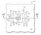
- FIG. 1is a top view of an electronic device with a shielding structure in accordance with an exemplary embodiment of the present invention
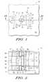
- FIG. 2is a cross-sectional view of the shielding structure of FIG. 1 along plane II-II;
- FIG. 3is a top view of an electronic device with a shielding structure in accordance with another exemplary embodiment of the present invention.
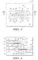
- FIG. 4is a cross-sectional view of the shielding structure of FIG. 3 along plane IV-IV;
- FIG. 5is a top view of an electronic device with a shielding structure in accordance with another exemplary embodiment of the present invention.
- FIG. 6is a cross-sectional view of the shielding structure of FIG. 5 along plane VI-VI;
- FIG. 7is a cross-sectional view of the shielding structure of FIG. 5 along plane VII-VII;
- FIG. 8is a flow chart illustrating a method for manufacturing an electronic device with a shielding structure in accordance with an exemplary embodiment of the present invention.
- FIG. 1is a top view of an electronic device 100 that utilizes a shielding structure 102 in accordance with an exemplary embodiment of the present invention
- FIG. 2illustrates a cross-sectional view of the electronic device 100 with the shielding structure 102 along plane II-II of FIG. 1
- the electronic device 100can be an electronic module with a plurality of layers, such as, for example, insulating layers 103 , 104 , 106 , 108 , 110 , and 112 , stacked sequentially on top of each other.
- the insulating layers 103 , 104 , 106 , 108 , 110 , and 112may comprise any dielectric material, such as for example, a ceramic, a silicon oxide, or TeOS.
- a layer 114may be an additional insulating layer or may be a semiconductor substrate, such as a silicon substrate.
- One or more intervening insulating layers 144 , 146 , and 148may also be provided adjacent and/or between the various layers 103 , 104 , 106 , 108 , 110 , 112 , and 114 .
- an intervening insulating layer 144is provided between the insulating layer 104 and the insulating layer 106 .
- An intervening insulating layer 146is provided between the insulating layer 110 and the insulating layer 112 .
- An intervening insulating layer 148is provided between the insulating layer 112 and the layer 114 .
- the term “intervening insulating layer”can be any layer that insulates a signal from a laterally adjacent portion of an electronic device.
- the “intervening insulating layer”can refer to a void in an otherwise conductive layer.
- the intervening insulating layer 144insulates a signal path 150 from an area metallization 136 , which is discussed in further detail below.
- One or more area metallizations 134 , 136 , 138 , and 140can also be provided within the device 100 .
- an area metallization 134is provided within the insulating layer 103 .
- An area metallization 136is also provided within the intervening insulating layer 144 .
- An area metallization 138is provided within the intervening insulating layer 146 .
- An area metallization 140is provided within the intervening insulating layer 148 .
- the area metallizations 134 , 136 , 138 , and 140can be solid, planar layers, perforated layers of conductive material, or any type of connection such as a connection trace line.
- the area metallizations 134 , 136 , 138 , and 140are formed by depositing suitable conductive material in trenches formed in the respective layer 103 , 144 , 146 , and 148 . Alternately, the area metallizations are deposited and then etched for subsequently depositing the respective intervening insulating layers 103 , 144 , 146 , and 148 .
- FIG. 2illustrates five insulating layers 104 , 106 , 108 , 110 , and 112 between the layers 103 and 114 ; however, in an alternate embodiment, the layers 103 and 114 are adjacent to one another.
- the electronic device 100can include a greater number or fewer number of area metallizations 134 , 136 , 138 , and 140 and intervening insulating layers 144 , 146 , and 148 . Additionally, other types of layers can be provided.
- the electronic device 100includes a plurality of interconnected modules.
- the electronic device 100includes the signal path 150 that transitions from a terminal 116 to a terminal 118 in a transition region 152 .
- the signal path 150has been outlined in bold in FIGS. 1 and 2 .
- the signal path 150extends from the terminal 116 in the insulating layer 103 , through an interconnect via 120 extending through the insulating layer 104 , and to a signal trace line 122 in the intervening insulating layer 144 .
- the signal path 150continues through an interconnect via 124 that extends through the insulating layer 106 , the insulating layer 108 , and the insulating layer 110 to a signal trace line 126 in the intervening insulating layer 146 .
- An interconnect via 129extends from the signal trace line 126 , through the insulating layer 112 , to the terminal 118 in the intervening insulating layer 148 .
- the signal trace lines 122 and 126can be, for example, microstrip lines or coplanar waveguides.
- the signal path 150 in the illustrated embodiment of FIGS. 1 and 2is shown extending between the terminals 116 and 118 , it will be appreciated that the signal path 150 can transition between additional external terminals and internal pads.
- the term “signal path”can refer to a path between two terminals, i.e., the beginning and/or end of a signal path, between two signal trace lines, or any portion of a larger signal path.
- transition regioncan refer to any portion of the signal path with at least one transition.
- transitioncan refer to any portion of a signal path that extends between at least two layers and wherein the signal travels in at least two directions, generally orthogonal to one another.
- a transition 154 and a transition 156are emphasized in FIG. 2 to better explain the one or more transitions that make up the transition region 152 .
- the transition 154includes at least a portion of the interconnect via 120 in the insulating layer 104 and at least a portion of the signal trace line 122 in the intervening insulating layer 144 .
- the transition 156includes at least a portion of the signal trace 126 and at least a portion of the interconnect via 129 in the insulating layer 112 . It will be appreciated that other transitions are also within the illustrated transition region 152 .
- the shielding structure 102is in proximity to the signal path 150 at the transition region 152 and includes a plurality of shielding vias 130 proximate to at least two areas, such as sides, corners, surfaces, regions, or the like of the signal path 150 .
- the shielding vias 130can be on any side of the signal path 150 , including opposing sides of the signal path 150 as shown in FIG. 2 .
- the shielding vias 130include one or more through vias 127 and/or one or more micro vias 128 .
- the through vias 127are vias that extend through at least two layers, such as through the insulating layer 106 , the insulating layer 108 , and the insulating layer 110
- the micro vias 128are vias that extend through one layer, such as through the insulating layer 104 or through the insulating layer 112 .
- Each of the through vias 127 and micro vias 128can be a laser drilled or chemically etched hole, which is then filled with conductive materials to provide vertical connection between the respective layers.
- Each of the through vias 127 and micro vias 128can have any suitable cross-sectional shape, such as for example, circular, square, or rectangular.
- the conductive materialscan be, for example, tungsten, copper, gold, or electrically conductive polymers.
- the area metallizations 134 , 136 , 138 , and 140can form part of the shielding structure 102 , and are coupled to the shielding vias 130 .
- the area metallizations 134 , 136 , 138 , and 140can provide a connection for the shielding vias 130 to effectively shield all or part the signal path 150 , including the transition region 152 .
- the area metallizations 134 , 136 , 138 , and 140can extend between the shielding vias 130 , i.e., the footprint of the shielding vias 130 , or the area metallizations 134 , 136 , 138 , and 140 can extend beyond one or more of the shielding vias 130 .
- the conductive metal suitable for the area metallizations 134 , 136 , 138 , and 140can include copper, aluminum, gold or the combination of other type of shielding materials.
- the area metallizationscan have a thickness of, for example, 5 ⁇ m to 25 ⁇ m.
- the area metallizations 134 , 136 , 138 , and 140 and shielding vias 130 of the shielding structure 102can provide a shield for EMI on all sides of the transition region 152 of the signal path 150 , e.g., the area metallizations 134 , 136 , 138 , and 140 can be above and below the signal path 150 and the shielding vias 130 can be on opposing sides of the transition region 152 of the signal path 150 as shown in FIG. 2 .
- current flowing in other signal paths and other sourcescan induce EMI that would otherwise interfere with the signal path 150 , particularly at the transition region 152 .
- the shielding structure 102prevents the EMI from interfering with the signal path 150 by confining or reflecting the EMI.
- the shielding structure 102provides protection for the signal path 150 from external EMI and minimizes the emission from signal path 150 itself.
- the EMImay induce a current in the shielding structure 102 instead of producing an unwanted current in the signal path 150 .
- the shielding structure 102is grounded.
- the shielding structure 102can include shielding structure portions (e.g., 158 and 160 in FIG. 2 ) to shield individual transitions (e.g., 154 and 156 ).
- shielding structures portions 158 and 160are emphasized in FIG. 2 for clarity.
- the shielding structure portion 158shields the transition 154 and includes the micro vias 128 in the insulating layer 104 on either side of the transition 154 and the area metallizations 134 and 136 .
- the shielding structure portion 160shields the transition 156 and includes the micro vias 128 in the insulating layer 112 on either side of the transition 156 and the area metallizations 138 and 140 .
- the shielding structure portions 158 and 160can be electrically connected with the through vias 127 , for example, to shield the transition from the signal trace line 122 to the interconnect via 124 proximate to the transition 154 and the transition from the interconnect via 124 to the signal trace line 126 proximate to transition 156 .
- the shielding structure portions 158 and 160can be considered two separate shielding structures.
- Other combinations of the shielding vias 130 and area metallizations 134 , 136 , 138 , and 140can be considered part of the shielding structure portions for the transitions 154 and 156 , as well as part of other shielding structure portions for other transitions.
- the more shielding vias 130 and area metallizations 134 , 136 , 138 , and 140 associated with each transitionthe better the shielding.
- FIG. 3is a top view of an electronic device 200 that utilizes a shielding structure 202 in accordance with another exemplary embodiment of the present invention
- FIG. 4illustrates a cross-sectional view of the electronic device 200 with the shielding structure 202 along plane IV-IV of FIG. 3
- the electronic device 200can be an electronic module with a plurality of layers, such as, for example, an insulating layer 204 , an insulating layer 206 , an insulating layer 208 , an insulating layer 210 , an insulating layer 212 , and a layer 214 stacked sequentially on top of each other.
- the layer 214may be an additional insulating layer or may be a semiconductor substrate, such as a silicon substrate.
- the insulating layers 204 , 206 , 208 , 210 , and 212may comprise any dielectric material, for example, ceramic, flame resistant 4 (FR- 4 ), silicon oxides, and similar materials.
- One or more intervening insulating layers 240 , 242 , and 244may also be provided adjacent and/or between the various insulating layers 204 , 206 , 208 , 210 , 212 , and 214 .
- an intervening insulating layer 240is provided between the insulating layer 206 and the insulating layer 208 .
- An intervening insulating layer 242is provided between the insulating layer 208 and the insulating layer 210 .
- An intervening insulating layer 244is provided between the insulating layer 210 and the insulating layer 212 .
- One or more area metallizations 230 , 232 , 234 , 236 , and 238can also be provided.
- an area metallization 230is provided between the insulating layer 204 and the insulating layer 206 .
- An area metallization 232is provided within the intervening insulating layer 240 .
- An area metallization 234is provided within the intervening insulating layer 242 .
- An area metallization 236is provided within the intervening insulating layer 244 .
- An area metallization 238is provided between the insulating layer 212 and the insulating layer 214 .
- the area metallizations 230 , 232 , 234 , 236 , and 238can be solid, planar layers, perforated layers of conductive material, or any type of connection such as a connection trace line.
- the area metallizations 232 , 234 , and 236are formed by depositing suitable conductive material in trenches formed in the respective intervening layer 240 , 242 , and 244 .
- the area metallizations 232 , 234 , and 236are deposited and then etched for subsequently depositing the respective intervening insulating layers 240 , 242 , and 244 .
- the electronic device 200can include a signal path 250 that transitions from a terminal 216 to a terminal 218 in a transition region 252 .
- the signal path 250has been outlined in bold in FIGS. 3 and 4 .
- the signal path 250extends from the terminal 216 in the intervening insulating layer 240 , and through a signal trace line 220 to an interconnect via 222 .
- the interconnect via 222extends through the insulating layer 208 , through the intervening insulating layer 242 , and through the insulating layer 210 to a signal trace line 224 in the intervening insulating layer 244 .
- the signal trace line 224extends to the terminal 218 , also in the intervening insulating layer 244 , to complete the signal path 250 from the terminal 216 to the terminal 218 .
- the signal path 250includes one or more transitions (e.g., 254 and 256 ).
- the transition 254includes at least a portion of the signal trace line 220 and at least a portion of the interconnect via 222
- the transition 256includes at least a portion of the interconnect via 222 and at least a portion of the signal trace line 224 . It will be appreciated that other transitions are also within the transition region 254 depicted within FIG. 4 .
- the shielding structure 202protects the signal path 250 from interference, particularly in the transition region 252 .
- the shielding structure 202includes one or more shielding vias 226 on at least two sides of the signal path 250 .
- FIGS. 3 and 4illustrate one embodiment that includes twenty-four shielding vias 226 , twelve of which are shown in FIG. 4 in the insulating layer 206 , the insulating layer 208 , the insulating layer 210 , and the insulating layer 212 .
- each of the shielding vias 226can be a laser drilled or chemically etched hole, which is then filled with conductive materials to provide vertical connection between the respective layers.
- the conductive materialscan be, for example, tungsten, copper, gold, or other electrically conductive polymers.
- Each of the shielding vias 226can have any suitable cross-sectional shape, such as for example, circular, square, or rectangular.
- the area metallizations 230 , 232 , 234 , 236 , and 238can form part of the shielding structure 202 , and are coupled to the shielding vias 226 .
- the area metallizations 230 , 232 , 234 , 236 , and 238can provide a ground for the shielding vias 226 to effectively shield the signal path 250 , including the transition region 252 .
- the area metallizations 230 , 232 , 234 , 236 , and 238can extend between the shielding vias 226 , i.e., the footprint of the shielding vias 226 , or the area metallizations 230 , 232 , 234 , 236 , and 238 can extend beyond the shielding vias 226 .
- the area metallizations 230 , 234 , 236 , and 238 and the shielding vias 226can provide EMI shielding in at least two areas, preferably four areas, of the transition region 252 of the signal path 250 . In an exemplary embodiment, the at least two areas are on opposing sides.
- the shielding structure 202can include shielding structure portions (e.g., 258 and 260 in FIG. 4 ) to shield individual transitions (e.g., 254 and 256 ).
- shielding structures portions 258 and 260are described in detail for clarity.
- the shielding structure portion 258shields the transition 254 and includes two of the micro vias 226 in the insulating layer 208 on either side of the transition 254 and the area metallizations 230 , 232 and 234 . It will be appreciated that other shielding vias and area metallizations can contribute to the shielding of the transition 254 , such as for example, the micro vias 226 in the insulating layer 206 .
- the shielding structure portion 260shields the transition 256 and includes the micro vias 226 in the insulating layer 212 on either side of the transition 256 and the area metallizations 236 and 234 . It will be appreciated that other shielding vias and area metallizations can contribute to the shielding of the transition 256 , such as for example, the micro vias 226 in the insulating layer 210 and the area metallization 238 . Other combinations of the shielding vias 226 and area metallizations 230 , 232 , 234 , 236 , and 238 can be considered part of the shielding structure portions for the transitions 254 and 256 , as well as part of other shielding structure portions for other transitions. Generally, the more shielding vias 226 and area metallizations 230 , 232 , 234 , 236 , and 238 associated with each transition, the better the shielding.
- another exemplary embodiment of the present inventionincludes an electronic device 300 formed by two electronic modules 304 and 306 and utilizes a shielding structure 302 .
- the shielding structure 302 in the electronic device 300shields a signal path 350 transitioning between the electronic module 304 and the electronic module 306 at a transition region 352 .
- the signal path 350has been outlined in bold in FIGS. 5-7 .
- the electronic device 300can be a flip chip module, which includes the electronic module 304 as a die and the electronic module 306 as a package substrate.
- Each of the electronic modules 304 and 306can have one or more functional components.
- the electronic module 304includes at least one layer, such as for example, four layers 307 , 308 , 310 , and 312 .
- the four layers of the electronic module 304can include an insulating layer 307 , an insulating layer 308 , an insulating layer 310 , and a layer 312 .
- the layer 312may be an insulating layer or may be a semiconductor substrate, such as a silicon-containing substrate.
- the electronic module 304can further include one or more area metallizations 334 and 338 .
- an area metallization 334can be provided within the insulating layer 307
- an area metallization 338can be provided between the insulating layer 310 and the insulating layer 312 .
- the electronic module 306includes at least one layer, such as for example, five insulating layers 313 , 314 , 316 , 318 , and 320 .
- a layer 322may be an insulating layer or may be a semiconductor substrate, such as a silicon-containing substrate.
- the electronic module 306can further include one or more intervening insulating layers, such as an intervening insulating layer 368 between the insulating layer 314 and the insulating layer 316 .
- One or more area metallizations 340 , 342 , and 344can also be provided.
- an area metallization 340is provided within the insulating layer 313 .
- An area metallization 342is provided within the intervening insulating layer 368
- an area metallization 344is provided between the insulating layer 320 and the insulating layer 322 .
- the signal path 350can extend from a signal trace line 324 between the insulating layer 308 and the insulating layer 310 of the electronic module 304 to an interconnect via 326 .
- the signal path 350can extend to other layers, such as the layer 312 and/or the layer 322 .
- the interconnect via 326can be a micro via that extends from the signal trace line 324 , and through the insulating layer 308 to a pad 327 formed within the insulating layer 307 .
- an interconnect via 329extends from a signal trace line 328 between the insulating layers 318 and 320 and through the insulating layer 318 , the insulating layer 316 , the intervening insulating layer 368 , the insulating layer 314 , and to a pad 331 formed within the intervening insulating layer 313 .
- the pad 331 of the module 306 and the pad 327 of the module 304can be coupled by an interconnect bump 335 to thus couple the modules 304 and 306 together and complete the signal path 350 .
- the interconnect bump 335can be a Land Grid Array (LGA), flip-chip bump, copper-pillar bump, or similar connection mechanism.
- the signal trace lines 324 and 328can be, for example, microstrip lines or coplanar waveguides. Underfill 337 can also be provided to secure the modules 304 and 306 together.
- a transition 354is emphasized in FIGS. 6 and 7 to better explain the one or more transitions that make up a transition region 352 for the signal path 350 .
- the transition 354includes at least a portion of the signal trace line 324 and at least a portion of the interconnect via 326 .
- a transition 358includes at least a portion of the signal trace 328 and at least a portion of the interconnect via 329 .
- the shielding structure 302is in proximity to the signal path 350 at the transition region 352 and includes one or more shielding vias 333 on at least two sides of the signal path 350 .
- the shielding vias 333can include one or more micro vias 330 and/or one or more through vias 332 .
- the shielding structurecan also include one or more bumps 370 that extended between the modules 304 and 306 .
- the through vias 332extend through more than one layer, and the micro vias 330 extend through one layer.
- the area metallizations 334 , 336 , 338 , 340 , 342 , and 344can form part of the shielding structure 302 , and are coupled to the shielding vias 333 and the bumps 370 .
- the area metallizations 334 , 336 , 338 , 340 , 342 , and 344 , together with shielding vias 333 and bumps 370 ,can effectively shield the signal path 350 .
- the area metallizations 334 , 336 , 338 , 340 , 342 , and 344can extend between the shielding vias 333 , i.e., the footprint of the shielding vias 333 , or the area metallizations 334 , 336 , 338 , 340 , 342 , and 344 can extend beyond the shielding vias 333 .
- the shielding structure 302can include shielding structure portions (e.g., 356 and 360 in FIG. 6 ) to shield individual transitions (e.g., 354 and 358 ).
- shielding structures portions 356 and 360are emphasized in FIG. 6 for clarity.
- the shielding structure portion 356shields the transition 354 and includes two of the through vias 332 in the insulating layer 308 and the insulating layer 310 on either side of the transition 354 and the area metallizations 334 and 338 .
- the shielding structure portion 360shields the transition 358 and includes the through vias 332 in the insulating layer 316 , the insulating layer 318 , and the insulating layer 320 on either side of the transition 358 and the area metallizations 342 and 344 .
- the shielding structure portions 356 and 360can be electrically connected and/or grounded to provide a complete shielding system, although it can be appreciated that the shielding structure portions 356 and 360 can be considered separate shielding structures.
- shielding vias 333 and area metallizations 334 , 336 , 338 , 340 , 342 , and 344can be considered part of the shielding structure portions for the transitions 354 and 358 , as well as part of other shielding structure portions for other transitions.
- area metallization 336can be considered part of the shielding structure portion 360 , or for example, the through vias 332 that extend through the insulating layer 316 , the insulating layer 318 , and the insulating layer 320 can be replaced with one or more micro vias and/or one or more additional area metallizations.
- the more shielding vias 333 and area metallizations 334 , 336 , 338 , 340 , 342 , and 344 associated with each transitionthe better the shielding.
- Embodiments of the shielding structures 102 , 202 , and 302provide continuous shielding for the signal path 150 , 250 , and 350 between two terminals, such as the terminals 116 and 118 , terminals 216 and 218 and/or the signal trace lines 324 and 328 , and particularly in transition regions 152 , 252 , and 352 , respectively.
- the shielding structures 102 , 202 , and 302can further provide an integrated and continuous grounding and a complete system level shielding, for example, for single line signal paths and differential signal paths.
- the shielding structures 102 , 202 , and 302substantially encapsulate and provide an electrically isolated environment for the signal path 150 , 250 , and 350 that shield the signal path from EMI.
- the number, placement, and type of shielding vias 130 , 226 , and 333 and/or bumps 370can be varied to optimize performance.
- the shielding vias 130 , 226 , and 333 and/or bumps 370are positioned, for example within 20, 40, 100, 300 microns, or greater from the signal path 150 , 250 , and 350 .
- the shielding vias 130 , 226 , and 333 and/or bumps 370can be placed on additional sides of the signal path 150 , 250 , and 350 , for example, on third and fourth sides of the signal path 150 , 250 , and 350 .
- the density of the shielding vias 130 , 226 , and 333 and/or bumps 370can also be increased or decreased depending on the desired shielding characteristics.
- the size, shape, and position of the area metallizations 134 , 136 , 138 , and 140 , the area metallizations 230 , 232 , 234 , 236 , and 238 , and the area metallizations 334 , 336 , 338 , 340 , 342 , and 344can be varied to optimize performance.
- the frequency range and the desired signal integrity of the particular applicationat least partially dictate the design of the shielding structure 102 , 202 , 302 .
- Design tools for signal integrity and three-dimensional electromagnetic (EM) analysiscan be utilized to optimize the placement and arrangement of the shielding structures 102 , 202 , 302 , for example, in ultra-wide band applications.
- the signal pathcan include a transition region with at least one transition of the signal path that extends in a first direction and a second direction orthogonal to the first direction.
- the methodfurther comprises forming a shielding structure in proximity to the signal path (step 420 ).
- the shielding structurecan include a plurality of shielding vias on either side of the signal path, particularly, for example, at the at least one transition, and one or more area metallizations coupled to the plurality of shielding vias.
- the first and second layerscan be in a single semiconductor module or a multiple semiconductor modules.
- the first layeris a die layer
- the second layeris a package substrate layer.
- portions of the shielding structurescan be formed simultaneously with the formation of portions of the signal path.
- Embodiments of the present inventioncan provide a system level signal integrity for all critical signal paths in a multi-layer module and between modules in multi-module electronic devices.
- Embodiments of the shielding structurescan be provided for single signals, differential signals, and multiple non-harmonious signals. Moreover, by providing a shielding structure within an electronic device, external shielding does not have to be added by the manufacturer or the customer.
- Embodiments of the present inventioncan be used in high performance applications, ultra wide band applications, millimeter wave RF applications, and/or high speed digital applications.
- a shielding structurefor shielding a signal path extending between a first layer and a second layer in an electronic device at a transition region with a transition that extends in a first direction and a second direction orthogonal to the first direction.
- the shielding structureincludes a shielding structure portion, which includes a first shielding via in proximity to a first area of the signal path at the transition; a second shielding via in proximity to a second area of the signal path at the transition; and an area metallization electrically coupled to the first shielding via.
- the area metallizationcan additionally be electrically coupled to the second shielding via.
- the first layercan be a layer in a first module and the second layer is in a second module.
- the signal pathcan include an interconnect bump extending from the first module to the second module, and the shielding structure portion can include a shielding bump in proximity to the interconnect bump.
- the area metallizationcan be a first area metallization of the first module, and the shielding structure portion can further include a second area metallization of the second module with the shielding bump extending from the first area metallization to the second area metallization.
- the shielding structure portioncan further include a third shielding via in proximity to a third area of the signal path at the transition and a fourth shielding via in proximity to a fourth area of the signal path at the transition.
- the area metallizationcan be a first area metallization above the transition and the shielding structure can further include a second area metallization below the transition.
- the area metallizationcan ground the first shielding via.
- a first plurality of shielding vias and a second plurality of shielding viascan extend in proximity to the signal path from a signal start point to a signal end point.
- an electronic devicein accordance with another exemplary embodiment, includes a first layer; a second layer overlying the first layer; a signal line extending between the first and second layers and having a transition region with at least one transition extending in first and second directions, orthogonal to one another; and a shielding structure for shielding the signal line proximate to the transition region.
- the shielding structureincludes a shielding structure portion having a first shielding via in proximity to a first area of the signal path at the transition, a second shielding via in proximity to a second area of the signal path at the transition on an opposing side of the first area, and an area metallization electrically coupled to the first shielding via.
- the shielding structure portion of the shielding structurecan further include a third shielding via in proximity to a third area of the signal path at the transition and a fourth shielding via in proximity to a fourth area of the signal path at the transition.
- the area metallizationcan be additionally electrically coupled to the second shielding via.
- the area metallizationcan ground the first shielding via and the second shielding via.
- the signal pathcan include a start point at the first layer and an end point at the second layer, and a first plurality of shielding vias and a second plurality of shielding vias can extend in proximity to substantially all of the signal path from the start point to the end point.
- the first shielding via and the second shielding viacan each include a through via or a micro via.
- the signal linecan be a single signal line or a differential signal line.
- the first shielding via and the second shielding viacan be within 100 microns of the signal line.
- the electronic devicecan include a first module and a second module coupled to the first module, and the signal path can include an interconnect bump extending between the first and second module.
- the area metallizationcan be a first area metallization of the first module and the shielding structure can further include a second area metallization of the second module and a shielding bump extending between the first and second area metallizations.
- the first modulecan be a flip-chip.
- a method of manufacturing an electronic devicecomprises the steps of: forming a first layer and a second layer with a signal path transitioning from the first layer to the second layer and having a transition region with a transition extending in a first direction and a second direction orthogonal to the first direction; and forming a shielding structure in proximity to two areas of the signal path at the transition.
- the shielding structureincludes a first shielding via proximate to a first area of the signal path at the transition, a second shielding via proximate to a second side of the signal path at the transition, and an area metallization coupled to the first shielding via and the second shielding via.
- the step of forming the first layer and the second layer and the step of forming the shielding structurecan be performed simultaneously
Landscapes
- Physics & Mathematics (AREA)
- Engineering & Computer Science (AREA)
- Microelectronics & Electronic Packaging (AREA)
- Electromagnetism (AREA)
- Condensed Matter Physics & Semiconductors (AREA)
- General Physics & Mathematics (AREA)
- Computer Hardware Design (AREA)
- Power Engineering (AREA)
- Semiconductor Integrated Circuits (AREA)
- Internal Circuitry In Semiconductor Integrated Circuit Devices (AREA)
Abstract
Description
Claims (9)
Priority Applications (2)
| Application Number | Priority Date | Filing Date | Title |
|---|---|---|---|
| US11/741,870US7869225B2 (en) | 2007-04-30 | 2007-04-30 | Shielding structures for signal paths in electronic devices |
| US12/962,893US8385084B2 (en) | 2007-04-30 | 2010-12-08 | Shielding structures for signal paths in electronic devices |
Applications Claiming Priority (1)
| Application Number | Priority Date | Filing Date | Title |
|---|---|---|---|
| US11/741,870US7869225B2 (en) | 2007-04-30 | 2007-04-30 | Shielding structures for signal paths in electronic devices |
Related Child Applications (1)
| Application Number | Title | Priority Date | Filing Date |
|---|---|---|---|
| US12/962,893DivisionUS8385084B2 (en) | 2007-04-30 | 2010-12-08 | Shielding structures for signal paths in electronic devices |
Publications (2)
| Publication Number | Publication Date |
|---|---|
| US20080266829A1 US20080266829A1 (en) | 2008-10-30 |
| US7869225B2true US7869225B2 (en) | 2011-01-11 |
Family
ID=39886710
Family Applications (2)
| Application Number | Title | Priority Date | Filing Date |
|---|---|---|---|
| US11/741,870Active2029-11-08US7869225B2 (en) | 2007-04-30 | 2007-04-30 | Shielding structures for signal paths in electronic devices |
| US12/962,893Active2027-05-24US8385084B2 (en) | 2007-04-30 | 2010-12-08 | Shielding structures for signal paths in electronic devices |
Family Applications After (1)
| Application Number | Title | Priority Date | Filing Date |
|---|---|---|---|
| US12/962,893Active2027-05-24US8385084B2 (en) | 2007-04-30 | 2010-12-08 | Shielding structures for signal paths in electronic devices |
Country Status (1)
| Country | Link |
|---|---|
| US (2) | US7869225B2 (en) |
Cited By (1)
| Publication number | Priority date | Publication date | Assignee | Title |
|---|---|---|---|---|
| US9589908B1 (en) | 2015-09-29 | 2017-03-07 | Nxp Usa, Inc. | Methods to improve BGA package isolation in radio frequency and millimeter wave products |
Families Citing this family (2)
| Publication number | Priority date | Publication date | Assignee | Title |
|---|---|---|---|---|
| US7977785B2 (en)* | 2009-03-05 | 2011-07-12 | Freescale Semiconductor, Inc. | Electronic device including dies, a dielectric layer, and a encapsulating layer |
| US10477672B2 (en)* | 2018-01-29 | 2019-11-12 | Hewlett Packard Enterprise Development Lp | Single ended vias with shared voids |
Citations (38)
| Publication number | Priority date | Publication date | Assignee | Title |
|---|---|---|---|---|
| US5414597A (en) | 1994-05-04 | 1995-05-09 | Ford Motor Company | Shielded circuit module |
| US6219254B1 (en) | 1999-04-05 | 2001-04-17 | Trw Inc. | Chip-to-board connection assembly and method therefor |
| US20010013650A1 (en) | 1997-05-23 | 2001-08-16 | Goetz Martin P. | Circuit interconnect providing reduced crosstalk and simultaneous switching noise |
| EP1182913A1 (en) | 2000-08-25 | 2002-02-27 | Agere Systems Guardian Corporation | High speed circuit board interconnection |
| US6356448B1 (en) | 1999-11-02 | 2002-03-12 | Inceptechnologies, Inc. | Inter-circuit encapsulated packaging for power delivery |
| EP1189271A2 (en) | 1996-07-12 | 2002-03-20 | Fujitsu Limited | Wiring boards and mounting of semiconductor devices thereon |
| US20020057883A1 (en) | 2000-09-29 | 2002-05-16 | Kevin Malone | High speed optical subassembly with ceramic carrier |
| WO2002047172A1 (en) | 2000-12-08 | 2002-06-13 | Sophia Wireless, Inc. | A high frequency interconnect system using micromachined plugs and sockets |
| US6420208B1 (en) | 2000-09-14 | 2002-07-16 | Motorola, Inc. | Method of forming an alternative ground contact for a semiconductor die |
| US20030006851A1 (en) | 1999-01-22 | 2003-01-09 | John Wood | Electronic circuitry |
| US20030036259A1 (en) | 2001-08-16 | 2003-02-20 | Motorola, Inc. | High speed, low latency bus modulation method and apparatus including a semiconductor structure for implementing same |
| US20030034487A1 (en) | 2001-08-16 | 2003-02-20 | Motorola, Inc. | Transmission line interconnect |
| US20030051910A1 (en)* | 2001-09-20 | 2003-03-20 | Dyke Peter D. Van | Electrical and physical design integration method and apparatus for providing interconnections on first level ceramic chip carrier packages |
| US20030112091A1 (en) | 2000-11-03 | 2003-06-19 | Lemke Timothy A. | High speed, controlled impedance air dielectric circuit modules for electronic backplane systems |
| US20030119279A1 (en) | 2000-03-22 | 2003-06-26 | Ziptronix | Three dimensional device integration method and integrated device |
| US6601293B1 (en) | 1998-08-28 | 2003-08-05 | Amkor Technology, Inc. | Method of making an electromagnetic interference shield device |
| US20040000425A1 (en) | 2002-06-26 | 2004-01-01 | White George E. | Methods for fabricating three-dimensional all organic interconnect structures |
| US20040043643A1 (en) | 2001-11-30 | 2004-03-04 | Fci Americas Technology | Interconnect for electrically connecting a multichip module to a circuit substrate and processes for making and using same |
| US6803252B2 (en) | 2001-11-21 | 2004-10-12 | Sierra Monolithics, Inc. | Single and multiple layer packaging of high-speed/high-density ICs |
| US6822880B2 (en) | 2001-09-28 | 2004-11-23 | Raytheon Company | Multilayer thin film hydrogen getter and internal signal EMI shield for complex three dimensional electronic package components |
| US20040238939A1 (en) | 2001-01-04 | 2004-12-02 | Ping Wu | Multi-power ring chip scale package for system level integration |
| US20040251501A1 (en) | 2003-06-11 | 2004-12-16 | Broadcom Corporation | Coupling of signals between adjacent functional blocks in an integrated circuit chip |
| US20040266384A1 (en) | 2003-06-27 | 2004-12-30 | Davis Richard F. | High frequency and low noise interconnect system |
| US20050046510A1 (en) | 2003-09-03 | 2005-03-03 | Kerner Stephen R. | Embedded RF vertical interconnect for flexible conformal antenna |
| US20050046001A1 (en) | 2001-08-28 | 2005-03-03 | Tessera, Inc | High-frequency chip packages |
| US6867668B1 (en) | 2002-03-18 | 2005-03-15 | Applied Micro Circuits Corporation | High frequency signal transmission from the surface of a circuit substrate to a flexible interconnect cable |
| US20050067676A1 (en) | 2003-09-25 | 2005-03-31 | Mahadevan Dave S. | Method of forming a semiconductor package and structure thereof |
| US20050077634A1 (en) | 2003-02-25 | 2005-04-14 | Seaman Kevin L. | Optimization of routing layers and board space requirements for a ball grid array package |
| US20050085103A1 (en) | 2001-01-12 | 2005-04-21 | Litton Systems, Inc. | High speed, high density interconnect system for differential and single-ended transmission systems |
| US20050098886A1 (en) | 2003-11-08 | 2005-05-12 | Chippac, Inc. | Flip chip interconnection pad layout |
| US6919226B2 (en) | 2001-11-22 | 2005-07-19 | Sony Corporation | Method for producing a multi-chip circuit module including a multi-layered wiring section utilizing a via-on-via structure |
| US20050250310A1 (en) | 2002-07-03 | 2005-11-10 | Sony Corporation | Multi-layer interconnection circuit module and manufacturing method thereof |
| US20050287850A1 (en) | 2001-11-14 | 2005-12-29 | Minich Steven E | Electrical connectors having differential signal pairs configured to reduce cross-talk on adjacent pairs |
| US6984571B1 (en) | 1999-10-01 | 2006-01-10 | Ziptronix, Inc. | Three dimensional device integration method and integrated device |
| GB2416925A (en) | 2004-07-30 | 2006-02-08 | Agilent Technologies Inc | EMI shield for electronics testing system |
| WO2006019336A2 (en) | 2004-08-11 | 2006-02-23 | Andrey Petrovich Zemlianov | Impedance controlled interconnect substrate and package for high-frequency electronic device |
| US20060038168A1 (en) | 2001-05-21 | 2006-02-23 | Estes Michael J | Terahertz interconnect system and applications |
| US7013558B2 (en) | 2000-03-21 | 2006-03-21 | Spraylat Corp. | Method for shielding an electronic component |
- 2007
- 2007-04-30USUS11/741,870patent/US7869225B2/enactiveActive
- 2010
- 2010-12-08USUS12/962,893patent/US8385084B2/enactiveActive
Patent Citations (38)
| Publication number | Priority date | Publication date | Assignee | Title |
|---|---|---|---|---|
| US5414597A (en) | 1994-05-04 | 1995-05-09 | Ford Motor Company | Shielded circuit module |
| EP1189271A2 (en) | 1996-07-12 | 2002-03-20 | Fujitsu Limited | Wiring boards and mounting of semiconductor devices thereon |
| US20010013650A1 (en) | 1997-05-23 | 2001-08-16 | Goetz Martin P. | Circuit interconnect providing reduced crosstalk and simultaneous switching noise |
| US6601293B1 (en) | 1998-08-28 | 2003-08-05 | Amkor Technology, Inc. | Method of making an electromagnetic interference shield device |
| US20030006851A1 (en) | 1999-01-22 | 2003-01-09 | John Wood | Electronic circuitry |
| US6219254B1 (en) | 1999-04-05 | 2001-04-17 | Trw Inc. | Chip-to-board connection assembly and method therefor |
| US6984571B1 (en) | 1999-10-01 | 2006-01-10 | Ziptronix, Inc. | Three dimensional device integration method and integrated device |
| US6356448B1 (en) | 1999-11-02 | 2002-03-12 | Inceptechnologies, Inc. | Inter-circuit encapsulated packaging for power delivery |
| US7013558B2 (en) | 2000-03-21 | 2006-03-21 | Spraylat Corp. | Method for shielding an electronic component |
| US20030119279A1 (en) | 2000-03-22 | 2003-06-26 | Ziptronix | Three dimensional device integration method and integrated device |
| EP1182913A1 (en) | 2000-08-25 | 2002-02-27 | Agere Systems Guardian Corporation | High speed circuit board interconnection |
| US6420208B1 (en) | 2000-09-14 | 2002-07-16 | Motorola, Inc. | Method of forming an alternative ground contact for a semiconductor die |
| US20020057883A1 (en) | 2000-09-29 | 2002-05-16 | Kevin Malone | High speed optical subassembly with ceramic carrier |
| US20030112091A1 (en) | 2000-11-03 | 2003-06-19 | Lemke Timothy A. | High speed, controlled impedance air dielectric circuit modules for electronic backplane systems |
| WO2002047172A1 (en) | 2000-12-08 | 2002-06-13 | Sophia Wireless, Inc. | A high frequency interconnect system using micromachined plugs and sockets |
| US20040238939A1 (en) | 2001-01-04 | 2004-12-02 | Ping Wu | Multi-power ring chip scale package for system level integration |
| US20050085103A1 (en) | 2001-01-12 | 2005-04-21 | Litton Systems, Inc. | High speed, high density interconnect system for differential and single-ended transmission systems |
| US20060038168A1 (en) | 2001-05-21 | 2006-02-23 | Estes Michael J | Terahertz interconnect system and applications |
| US20030034487A1 (en) | 2001-08-16 | 2003-02-20 | Motorola, Inc. | Transmission line interconnect |
| US20030036259A1 (en) | 2001-08-16 | 2003-02-20 | Motorola, Inc. | High speed, low latency bus modulation method and apparatus including a semiconductor structure for implementing same |
| US20050046001A1 (en) | 2001-08-28 | 2005-03-03 | Tessera, Inc | High-frequency chip packages |
| US20030051910A1 (en)* | 2001-09-20 | 2003-03-20 | Dyke Peter D. Van | Electrical and physical design integration method and apparatus for providing interconnections on first level ceramic chip carrier packages |
| US6822880B2 (en) | 2001-09-28 | 2004-11-23 | Raytheon Company | Multilayer thin film hydrogen getter and internal signal EMI shield for complex three dimensional electronic package components |
| US20050287850A1 (en) | 2001-11-14 | 2005-12-29 | Minich Steven E | Electrical connectors having differential signal pairs configured to reduce cross-talk on adjacent pairs |
| US6803252B2 (en) | 2001-11-21 | 2004-10-12 | Sierra Monolithics, Inc. | Single and multiple layer packaging of high-speed/high-density ICs |
| US6919226B2 (en) | 2001-11-22 | 2005-07-19 | Sony Corporation | Method for producing a multi-chip circuit module including a multi-layered wiring section utilizing a via-on-via structure |
| US20040043643A1 (en) | 2001-11-30 | 2004-03-04 | Fci Americas Technology | Interconnect for electrically connecting a multichip module to a circuit substrate and processes for making and using same |
| US6867668B1 (en) | 2002-03-18 | 2005-03-15 | Applied Micro Circuits Corporation | High frequency signal transmission from the surface of a circuit substrate to a flexible interconnect cable |
| US20040000425A1 (en) | 2002-06-26 | 2004-01-01 | White George E. | Methods for fabricating three-dimensional all organic interconnect structures |
| US20050250310A1 (en) | 2002-07-03 | 2005-11-10 | Sony Corporation | Multi-layer interconnection circuit module and manufacturing method thereof |
| US20050077634A1 (en) | 2003-02-25 | 2005-04-14 | Seaman Kevin L. | Optimization of routing layers and board space requirements for a ball grid array package |
| US20040251501A1 (en) | 2003-06-11 | 2004-12-16 | Broadcom Corporation | Coupling of signals between adjacent functional blocks in an integrated circuit chip |
| US20040266384A1 (en) | 2003-06-27 | 2004-12-30 | Davis Richard F. | High frequency and low noise interconnect system |
| US20050046510A1 (en) | 2003-09-03 | 2005-03-03 | Kerner Stephen R. | Embedded RF vertical interconnect for flexible conformal antenna |
| US20050067676A1 (en) | 2003-09-25 | 2005-03-31 | Mahadevan Dave S. | Method of forming a semiconductor package and structure thereof |
| US20050098886A1 (en) | 2003-11-08 | 2005-05-12 | Chippac, Inc. | Flip chip interconnection pad layout |
| GB2416925A (en) | 2004-07-30 | 2006-02-08 | Agilent Technologies Inc | EMI shield for electronics testing system |
| WO2006019336A2 (en) | 2004-08-11 | 2006-02-23 | Andrey Petrovich Zemlianov | Impedance controlled interconnect substrate and package for high-frequency electronic device |
Cited By (1)
| Publication number | Priority date | Publication date | Assignee | Title |
|---|---|---|---|---|
| US9589908B1 (en) | 2015-09-29 | 2017-03-07 | Nxp Usa, Inc. | Methods to improve BGA package isolation in radio frequency and millimeter wave products |
Also Published As
| Publication number | Publication date |
|---|---|
| US8385084B2 (en) | 2013-02-26 |
| US20080266829A1 (en) | 2008-10-30 |
| US20110075394A1 (en) | 2011-03-31 |
Similar Documents
| Publication | Publication Date | Title |
|---|---|---|
| CN209929298U (en) | Chip package | |
| EP2548225B1 (en) | System-in-package using embedded-die coreless substrates, and processes of forming same | |
| KR100891763B1 (en) | Semiconductor device | |
| US10015881B2 (en) | Cavities containing multi-wiring structures and devices | |
| US8729709B2 (en) | Semiconductor device | |
| CN101207101B (en) | Pattern shielding structure for dry etching and method thereof | |
| US7436056B2 (en) | Electronic component package | |
| US9468089B2 (en) | EBG structure, semiconductor device, and circuit board | |
| US7772694B2 (en) | Integrated circuit module and method of packaging same | |
| WO2011021328A1 (en) | Semiconductor device having shield layer and element-side power supply terminal capacitively coupled therein | |
| JP2008010859A (en) | Semiconductor device | |
| JP2008112992A (en) | Multiple ground shield semiconductor package, method of manufacturing the package, and noise prevention method using the ground shield | |
| US9589908B1 (en) | Methods to improve BGA package isolation in radio frequency and millimeter wave products | |
| JP2010109269A (en) | Semiconductor device | |
| US8791369B2 (en) | Electronic component | |
| CN102881680A (en) | Semiconductor device and method of manufacturing same | |
| US7230332B2 (en) | Chip package with embedded component | |
| US8385084B2 (en) | Shielding structures for signal paths in electronic devices | |
| US9431337B2 (en) | Semiconductor device having an inner power supply plate structure | |
| US6430059B1 (en) | Integrated circuit package substrate integrating with decoupling capacitor | |
| JP3878795B2 (en) | Multilayer wiring board | |
| EP4243065A2 (en) | Microelectronic packages having coaxially-shielded radio frequency input/output interfaces | |
| US20100244274A1 (en) | Wiring board | |
| US20060145350A1 (en) | High frequency conductors for packages of integrated circuits | |
| JP3798978B2 (en) | Multilayer wiring board |
Legal Events
| Date | Code | Title | Description |
|---|---|---|---|
| AS | Assignment | Owner name:FREESCALE SEMICONDUCTOR, INC., TEXAS Free format text:ASSIGNMENT OF ASSIGNORS INTEREST;ASSIGNORS:TANG, JINBANG;MCBEAN, RONALD V.;LIN, JONG-KAI;REEL/FRAME:019377/0238;SIGNING DATES FROM 20070425 TO 20070428 Owner name:FREESCALE SEMICONDUCTOR, INC., TEXAS Free format text:ASSIGNMENT OF ASSIGNORS INTEREST;ASSIGNORS:TANG, JINBANG;MCBEAN, RONALD V.;LIN, JONG-KAI;SIGNING DATES FROM 20070425 TO 20070428;REEL/FRAME:019377/0238 | |
| AS | Assignment | Owner name:CITIBANK, N.A., AS COLLATERAL AGENT, NEW YORK Free format text:SECURITY AGREEMENT;ASSIGNOR:FREESCALE SEMICONDUCTOR, INC.;REEL/FRAME:020045/0448 Effective date:20070718 Owner name:CITIBANK, N.A., AS COLLATERAL AGENT,NEW YORK Free format text:SECURITY AGREEMENT;ASSIGNOR:FREESCALE SEMICONDUCTOR, INC.;REEL/FRAME:020045/0448 Effective date:20070718 | |
| AS | Assignment | Owner name:CITIBANK, N.A.,NEW YORK Free format text:SECURITY AGREEMENT;ASSIGNOR:FREESCALE SEMICONDUCTOR, INC.;REEL/FRAME:024085/0001 Effective date:20100219 Owner name:CITIBANK, N.A., NEW YORK Free format text:SECURITY AGREEMENT;ASSIGNOR:FREESCALE SEMICONDUCTOR, INC.;REEL/FRAME:024085/0001 Effective date:20100219 | |
| AS | Assignment | Owner name:CITIBANK, N.A., AS COLLATERAL AGENT,NEW YORK Free format text:SECURITY AGREEMENT;ASSIGNOR:FREESCALE SEMICONDUCTOR, INC.;REEL/FRAME:024397/0001 Effective date:20100413 Owner name:CITIBANK, N.A., AS COLLATERAL AGENT, NEW YORK Free format text:SECURITY AGREEMENT;ASSIGNOR:FREESCALE SEMICONDUCTOR, INC.;REEL/FRAME:024397/0001 Effective date:20100413 | |
| FEPP | Fee payment procedure | Free format text:PAYOR NUMBER ASSIGNED (ORIGINAL EVENT CODE: ASPN); ENTITY STATUS OF PATENT OWNER: LARGE ENTITY | |
| STCF | Information on status: patent grant | Free format text:PATENTED CASE | |
| AS | Assignment | Owner name:CITIBANK, N.A., AS NOTES COLLATERAL AGENT, NEW YORK Free format text:SECURITY AGREEMENT;ASSIGNOR:FREESCALE SEMICONDUCTOR, INC.;REEL/FRAME:030633/0424 Effective date:20130521 Owner name:CITIBANK, N.A., AS NOTES COLLATERAL AGENT, NEW YOR Free format text:SECURITY AGREEMENT;ASSIGNOR:FREESCALE SEMICONDUCTOR, INC.;REEL/FRAME:030633/0424 Effective date:20130521 | |
| AS | Assignment | Owner name:CITIBANK, N.A., AS NOTES COLLATERAL AGENT, NEW YORK Free format text:SECURITY AGREEMENT;ASSIGNOR:FREESCALE SEMICONDUCTOR, INC.;REEL/FRAME:031591/0266 Effective date:20131101 Owner name:CITIBANK, N.A., AS NOTES COLLATERAL AGENT, NEW YOR Free format text:SECURITY AGREEMENT;ASSIGNOR:FREESCALE SEMICONDUCTOR, INC.;REEL/FRAME:031591/0266 Effective date:20131101 | |
| FPAY | Fee payment | Year of fee payment:4 | |
| AS | Assignment | Owner name:FREESCALE SEMICONDUCTOR, INC., TEXAS Free format text:PATENT RELEASE;ASSIGNOR:CITIBANK, N.A., AS COLLATERAL AGENT;REEL/FRAME:037356/0553 Effective date:20151207 Owner name:FREESCALE SEMICONDUCTOR, INC., TEXAS Free format text:PATENT RELEASE;ASSIGNOR:CITIBANK, N.A., AS COLLATERAL AGENT;REEL/FRAME:037356/0143 Effective date:20151207 Owner name:FREESCALE SEMICONDUCTOR, INC., TEXAS Free format text:PATENT RELEASE;ASSIGNOR:CITIBANK, N.A., AS COLLATERAL AGENT;REEL/FRAME:037354/0655 Effective date:20151207 | |
| AS | Assignment | Owner name:MORGAN STANLEY SENIOR FUNDING, INC., MARYLAND Free format text:ASSIGNMENT AND ASSUMPTION OF SECURITY INTEREST IN PATENTS;ASSIGNOR:CITIBANK, N.A.;REEL/FRAME:037486/0517 Effective date:20151207 | |
| AS | Assignment | Owner name:MORGAN STANLEY SENIOR FUNDING, INC., MARYLAND Free format text:ASSIGNMENT AND ASSUMPTION OF SECURITY INTEREST IN PATENTS;ASSIGNOR:CITIBANK, N.A.;REEL/FRAME:037518/0292 Effective date:20151207 | |
| AS | Assignment | Owner name:MORGAN STANLEY SENIOR FUNDING, INC., MARYLAND Free format text:SECURITY AGREEMENT SUPPLEMENT;ASSIGNOR:NXP B.V.;REEL/FRAME:038017/0058 Effective date:20160218 | |
| AS | Assignment | Owner name:MORGAN STANLEY SENIOR FUNDING, INC., MARYLAND Free format text:SUPPLEMENT TO THE SECURITY AGREEMENT;ASSIGNOR:FREESCALE SEMICONDUCTOR, INC.;REEL/FRAME:039138/0001 Effective date:20160525 | |
| AS | Assignment | Owner name:MORGAN STANLEY SENIOR FUNDING, INC., MARYLAND Free format text:CORRECTIVE ASSIGNMENT TO CORRECT THE REMOVE APPLICATION 12092129 PREVIOUSLY RECORDED ON REEL 038017 FRAME 0058. ASSIGNOR(S) HEREBY CONFIRMS THE SECURITY AGREEMENT SUPPLEMENT;ASSIGNOR:NXP B.V.;REEL/FRAME:039361/0212 Effective date:20160218 | |
| AS | Assignment | Owner name:NXP, B.V., F/K/A FREESCALE SEMICONDUCTOR, INC., NETHERLANDS Free format text:RELEASE BY SECURED PARTY;ASSIGNOR:MORGAN STANLEY SENIOR FUNDING, INC.;REEL/FRAME:040925/0001 Effective date:20160912 Owner name:NXP, B.V., F/K/A FREESCALE SEMICONDUCTOR, INC., NE Free format text:RELEASE BY SECURED PARTY;ASSIGNOR:MORGAN STANLEY SENIOR FUNDING, INC.;REEL/FRAME:040925/0001 Effective date:20160912 | |
| AS | Assignment | Owner name:NXP B.V., NETHERLANDS Free format text:RELEASE BY SECURED PARTY;ASSIGNOR:MORGAN STANLEY SENIOR FUNDING, INC.;REEL/FRAME:040928/0001 Effective date:20160622 | |
| AS | Assignment | Owner name:NXP USA, INC., TEXAS Free format text:CHANGE OF NAME;ASSIGNOR:FREESCALE SEMICONDUCTOR, INC.;REEL/FRAME:040632/0001 Effective date:20161107 | |
| AS | Assignment | Owner name:MORGAN STANLEY SENIOR FUNDING, INC., MARYLAND Free format text:CORRECTIVE ASSIGNMENT TO CORRECT THE REMOVE PATENTS 8108266 AND 8062324 AND REPLACE THEM WITH 6108266 AND 8060324 PREVIOUSLY RECORDED ON REEL 037518 FRAME 0292. ASSIGNOR(S) HEREBY CONFIRMS THE ASSIGNMENT AND ASSUMPTION OF SECURITY INTEREST IN PATENTS;ASSIGNOR:CITIBANK, N.A.;REEL/FRAME:041703/0536 Effective date:20151207 | |
| AS | Assignment | Owner name:MORGAN STANLEY SENIOR FUNDING, INC., MARYLAND Free format text:CORRECTIVE ASSIGNMENT TO CORRECT THE REMOVE APPLICATION 12681366 PREVIOUSLY RECORDED ON REEL 039361 FRAME 0212. ASSIGNOR(S) HEREBY CONFIRMS THE SECURITY AGREEMENT SUPPLEMENT;ASSIGNOR:NXP B.V.;REEL/FRAME:042762/0145 Effective date:20160218 Owner name:MORGAN STANLEY SENIOR FUNDING, INC., MARYLAND Free format text:CORRECTIVE ASSIGNMENT TO CORRECT THE REMOVE APPLICATION 12681366 PREVIOUSLY RECORDED ON REEL 038017 FRAME 0058. ASSIGNOR(S) HEREBY CONFIRMS THE SECURITY AGREEMENT SUPPLEMENT;ASSIGNOR:NXP B.V.;REEL/FRAME:042985/0001 Effective date:20160218 | |
| AS | Assignment | Owner name:NXP USA, INC., TEXAS Free format text:CORRECTIVE ASSIGNMENT TO CORRECT THE NATURE OF CONVEYANCE PREVIOUSLY RECORDED AT REEL: 040632 FRAME: 0001. ASSIGNOR(S) HEREBY CONFIRMS THE MERGER AND CHANGE OF NAME;ASSIGNOR:FREESCALE SEMICONDUCTOR INC.;REEL/FRAME:044209/0047 Effective date:20161107 | |
| MAFP | Maintenance fee payment | Free format text:PAYMENT OF MAINTENANCE FEE, 8TH YEAR, LARGE ENTITY (ORIGINAL EVENT CODE: M1552) Year of fee payment:8 | |
| AS | Assignment | Owner name:SHENZHEN XINGUODU TECHNOLOGY CO., LTD., CHINA Free format text:CORRECTIVE ASSIGNMENT TO CORRECT THE TO CORRECT THE APPLICATION NO. FROM 13,883,290 TO 13,833,290 PREVIOUSLY RECORDED ON REEL 041703 FRAME 0536. ASSIGNOR(S) HEREBY CONFIRMS THE THE ASSIGNMENT AND ASSUMPTION OF SECURITYINTEREST IN PATENTS.;ASSIGNOR:MORGAN STANLEY SENIOR FUNDING, INC.;REEL/FRAME:048734/0001 Effective date:20190217 | |
| AS | Assignment | Owner name:NXP B.V., NETHERLANDS Free format text:RELEASE BY SECURED PARTY;ASSIGNOR:MORGAN STANLEY SENIOR FUNDING, INC.;REEL/FRAME:050744/0097 Effective date:20190903 Owner name:NXP B.V., NETHERLANDS Free format text:RELEASE BY SECURED PARTY;ASSIGNOR:MORGAN STANLEY SENIOR FUNDING, INC.;REEL/FRAME:050745/0001 Effective date:20190903 | |
| AS | Assignment | Owner name:MORGAN STANLEY SENIOR FUNDING, INC., MARYLAND Free format text:CORRECTIVE ASSIGNMENT TO CORRECT THE REMOVE APPLICATION 12298143 PREVIOUSLY RECORDED ON REEL 042985 FRAME 0001. ASSIGNOR(S) HEREBY CONFIRMS THE SECURITY AGREEMENT SUPPLEMENT;ASSIGNOR:NXP B.V.;REEL/FRAME:051029/0001 Effective date:20160218 Owner name:MORGAN STANLEY SENIOR FUNDING, INC., MARYLAND Free format text:CORRECTIVE ASSIGNMENT TO CORRECT THE REMOVE APPLICATION 12298143 PREVIOUSLY RECORDED ON REEL 042762 FRAME 0145. ASSIGNOR(S) HEREBY CONFIRMS THE SECURITY AGREEMENT SUPPLEMENT;ASSIGNOR:NXP B.V.;REEL/FRAME:051145/0184 Effective date:20160218 Owner name:MORGAN STANLEY SENIOR FUNDING, INC., MARYLAND Free format text:CORRECTIVE ASSIGNMENT TO CORRECT THE REMOVE APPLICATION 12298143 PREVIOUSLY RECORDED ON REEL 039361 FRAME 0212. ASSIGNOR(S) HEREBY CONFIRMS THE SECURITY AGREEMENT SUPPLEMENT;ASSIGNOR:NXP B.V.;REEL/FRAME:051029/0387 Effective date:20160218 Owner name:MORGAN STANLEY SENIOR FUNDING, INC., MARYLAND Free format text:CORRECTIVE ASSIGNMENT TO CORRECT THE REMOVE APPLICATION 12298143 PREVIOUSLY RECORDED ON REEL 038017 FRAME 0058. ASSIGNOR(S) HEREBY CONFIRMS THE SECURITY AGREEMENT SUPPLEMENT;ASSIGNOR:NXP B.V.;REEL/FRAME:051030/0001 Effective date:20160218 Owner name:MORGAN STANLEY SENIOR FUNDING, INC., MARYLAND Free format text:CORRECTIVE ASSIGNMENT TO CORRECT THE REMOVE APPLICATION12298143 PREVIOUSLY RECORDED ON REEL 042985 FRAME 0001. ASSIGNOR(S) HEREBY CONFIRMS THE SECURITY AGREEMENT SUPPLEMENT;ASSIGNOR:NXP B.V.;REEL/FRAME:051029/0001 Effective date:20160218 Owner name:MORGAN STANLEY SENIOR FUNDING, INC., MARYLAND Free format text:CORRECTIVE ASSIGNMENT TO CORRECT THE REMOVE APPLICATION12298143 PREVIOUSLY RECORDED ON REEL 039361 FRAME 0212. ASSIGNOR(S) HEREBY CONFIRMS THE SECURITY AGREEMENT SUPPLEMENT;ASSIGNOR:NXP B.V.;REEL/FRAME:051029/0387 Effective date:20160218 Owner name:MORGAN STANLEY SENIOR FUNDING, INC., MARYLAND Free format text:CORRECTIVE ASSIGNMENT TO CORRECT THE REMOVE APPLICATION12298143 PREVIOUSLY RECORDED ON REEL 042762 FRAME 0145. ASSIGNOR(S) HEREBY CONFIRMS THE SECURITY AGREEMENT SUPPLEMENT;ASSIGNOR:NXP B.V.;REEL/FRAME:051145/0184 Effective date:20160218 | |
| AS | Assignment | Owner name:MORGAN STANLEY SENIOR FUNDING, INC., MARYLAND Free format text:CORRECTIVE ASSIGNMENT TO CORRECT THE REMOVE APPLICATION11759915 AND REPLACE IT WITH APPLICATION 11759935 PREVIOUSLY RECORDED ON REEL 037486 FRAME 0517. ASSIGNOR(S) HEREBY CONFIRMS THE ASSIGNMENT AND ASSUMPTION OF SECURITYINTEREST IN PATENTS;ASSIGNOR:CITIBANK, N.A.;REEL/FRAME:053547/0421 Effective date:20151207 | |
| AS | Assignment | Owner name:NXP B.V., NETHERLANDS Free format text:CORRECTIVE ASSIGNMENT TO CORRECT THE REMOVEAPPLICATION 11759915 AND REPLACE IT WITH APPLICATION11759935 PREVIOUSLY RECORDED ON REEL 040928 FRAME 0001. ASSIGNOR(S) HEREBY CONFIRMS THE RELEASE OF SECURITYINTEREST;ASSIGNOR:MORGAN STANLEY SENIOR FUNDING, INC.;REEL/FRAME:052915/0001 Effective date:20160622 | |
| AS | Assignment | Owner name:NXP, B.V. F/K/A FREESCALE SEMICONDUCTOR, INC., NETHERLANDS Free format text:CORRECTIVE ASSIGNMENT TO CORRECT THE REMOVEAPPLICATION 11759915 AND REPLACE IT WITH APPLICATION11759935 PREVIOUSLY RECORDED ON REEL 040925 FRAME 0001. ASSIGNOR(S) HEREBY CONFIRMS THE RELEASE OF SECURITYINTEREST;ASSIGNOR:MORGAN STANLEY SENIOR FUNDING, INC.;REEL/FRAME:052917/0001 Effective date:20160912 | |
| MAFP | Maintenance fee payment | Free format text:PAYMENT OF MAINTENANCE FEE, 12TH YEAR, LARGE ENTITY (ORIGINAL EVENT CODE: M1553); ENTITY STATUS OF PATENT OWNER: LARGE ENTITY Year of fee payment:12 |