US7868843B2 - Slim multi-band antenna array for cellular base stations - Google Patents
Slim multi-band antenna array for cellular base stationsDownload PDFInfo
- Publication number
- US7868843B2 US7868843B2US11/660,802US66080205AUS7868843B2US 7868843 B2US7868843 B2US 7868843B2US 66080205 AUS66080205 AUS 66080205AUS 7868843 B2US7868843 B2US 7868843B2
- Authority
- US
- United States
- Prior art keywords
- dual
- multiband antenna
- arrays
- frequency
- radiating
- Prior art date
- Legal status (The legal status is an assumption and is not a legal conclusion. Google has not performed a legal analysis and makes no representation as to the accuracy of the status listed.)
- Expired - Fee Related, expires
Links
Images


Classifications
- H—ELECTRICITY
- H01—ELECTRIC ELEMENTS
- H01Q—ANTENNAS, i.e. RADIO AERIALS
- H01Q1/00—Details of, or arrangements associated with, antennas
- H01Q1/12—Supports; Mounting means
- H01Q1/22—Supports; Mounting means by structural association with other equipment or articles
- H01Q1/24—Supports; Mounting means by structural association with other equipment or articles with receiving set
- H01Q1/241—Supports; Mounting means by structural association with other equipment or articles with receiving set used in mobile communications, e.g. GSM
- H01Q1/246—Supports; Mounting means by structural association with other equipment or articles with receiving set used in mobile communications, e.g. GSM specially adapted for base stations
- H—ELECTRICITY
- H01—ELECTRIC ELEMENTS
- H01Q—ANTENNAS, i.e. RADIO AERIALS
- H01Q1/00—Details of, or arrangements associated with, antennas
- H01Q1/52—Means for reducing coupling between antennas; Means for reducing coupling between an antenna and another structure
- H01Q1/521—Means for reducing coupling between antennas; Means for reducing coupling between an antenna and another structure reducing the coupling between adjacent antennas
- H01Q1/523—Means for reducing coupling between antennas; Means for reducing coupling between an antenna and another structure reducing the coupling between adjacent antennas between antennas of an array
- H—ELECTRICITY
- H01—ELECTRIC ELEMENTS
- H01Q—ANTENNAS, i.e. RADIO AERIALS
- H01Q21/00—Antenna arrays or systems
- H01Q21/06—Arrays of individually energised antenna units similarly polarised and spaced apart
- H01Q21/061—Two dimensional planar arrays
- H01Q21/065—Patch antenna array
- H—ELECTRICITY
- H01—ELECTRIC ELEMENTS
- H01Q—ANTENNAS, i.e. RADIO AERIALS
- H01Q21/00—Antenna arrays or systems
- H01Q21/06—Arrays of individually energised antenna units similarly polarised and spaced apart
- H01Q21/20—Arrays of individually energised antenna units similarly polarised and spaced apart the units being spaced along or adjacent to a curvilinear path
- H01Q21/205—Arrays of individually energised antenna units similarly polarised and spaced apart the units being spaced along or adjacent to a curvilinear path providing an omnidirectional coverage
- H—ELECTRICITY
- H01—ELECTRIC ELEMENTS
- H01Q—ANTENNAS, i.e. RADIO AERIALS
- H01Q5/00—Arrangements for simultaneous operation of antennas on two or more different wavebands, e.g. dual-band or multi-band arrangements
- H01Q5/40—Imbricated or interleaved structures; Combined or electromagnetically coupled arrangements, e.g. comprising two or more non-connected fed radiating elements
- H01Q5/42—Imbricated or interleaved structures; Combined or electromagnetically coupled arrangements, e.g. comprising two or more non-connected fed radiating elements using two or more imbricated arrays
Definitions
- the present inventionrefers to a slim multi-band antenna array for cellular base stations, which provides a reduced width of the base station antenna and minimizes the environmental and visual impact of a network of cellular base station antennas, in particular in mobile telephony and wireless service networks.
- the inventionrelates to a generation of slim base station sites that are able to integrate multiple mobile/cellular services into a compact radiating system.
- a Multi Band antenna array of the inventioncomprises an interlaced arrangement of small radiating elements to significantly reduce the size of the antenna. More specifically the width of this antenna being similar to the width of a typical single band antenna so about half of the width of typical Dual Band antenna.
- the UMTS, third generation of wireless communications systems, that is being added to 2 nd generation of wireless communications systemshas created a demand for multiband antennas and in particular to Dual Band Base Station Antennas.
- the typical Dual band antennas that are used todayare side by side arrays where the size is typically twice of the size of a single band antenna.
- the typical width of Dual Band antennais around 2 wavelengths, which is about 30 cm in the case of an antenna operating at two of the following communication services DCS, PCS or UMTS while the width of a Single Band antenna is typically around one wavelength, which is around 15 cm in case of a DCS, PCS or UMTS antenna.
- the cellular servicesrequire several Base Stations that are composed by several base station antennas to give service to the cellular users.
- the antennasare the radiating part of the Base Station.
- the radiating part of the Base Stationis composed by nine or three independent antennas that give coverage to a specific part of the city, village, road, motorway.
- the size of the Base Stationis large and has a significant visual impact.
- the inventionprovides tools and means to minimize the visual impact and cost of mobile telecommunication networks while at the same time simplifying the logistics of the deployment, installation and maintenance of such networks.
- the inventionprovides a slim base station site which integrates multiple mobile/cellular services into a compact radiating system.
- the radiating systemincludes an adjustable electrical tilt system for one or more of the operating frequency bands, thus providing additional flexibility when planning, adjusting, and optimizing the coverage, and increasing the capacity of the network.
- the slim form factor of the radiating system as described by the present inventionenables slimmer, lighter towers to support such radiating systems, which are easier to carry to the roof of buildings (through elevators, through stairs or small gear systems) where the systems might be installed.
- such slim systemsenable such lighter and portable towers to be implemented as a cascading of modular elements, and also, to introduce folding, retracting or bending mechanisms for an easier installation.
- the slim sitecan be easily disguised in the form of other urban architectural elements (such as for instance street light poles, chimneys, flag posts, advertisement posts and so on) while at the same time integrating other equipment (such as filters, diplexers, tower mounted low-noise amplifiers and/or power amplifiers) in a single, compact unit.
- One aspect of the inventionrefers to a Slim Stacked dual band antenna array using compact antenna and compact phase shifter technology to allow the integration of three dual band antennas on a slim cylinder, that result in a base station of reduced size and reduced visual impact when compared to the radiating part of current base stations.
- the diameter of this slim array that compose the radiating part of the base stationis typically less than 2 wavelengths for the longest operating wavelength, and in some embodiments, such a diameter is less than 1.6, 1.5, 1.4 or 1.3 wavelengths, which is significantly smaller than the size of the radiating part of typical base stations.
- the inventiontherefore provides as well a method for reducing the size of the radiating part of the base station, and therefore a method for minimizing the environmental and visual impact of a network of cellular base station antennas. Also, this provides a means of reducing the cost of installation of the whole network, and a means to speed-up the deployment of the network.
- a particular embodiment of this inventionincludes a Dual Band and dual polarized array with independent variable down-tilt for each frequency band.
- the ratio between frequency bandsis less than 2, and in some preferred embodiments less than 1.6, 1.5, 1.4, 1.3, 1.2 and 1.15.
- this inventionis suitable for combining frequency bands such as UMTS and GSM1800 (DCS), UMTS with PCS1900 or in general two or more cellular or wireless systems operating in the vicinity of the 1700 MHz-2700 MHz frequency range.
- DCSUMTS and GSM1800
- the ratiois computed from the central frequencies of the band. In some embodiments the ratio is computed from other frequencies chosen at the two bands.
- the width and thickness of this antennais small compared to typical Dual Band base station antenna. Particularly the width is less than two wavelengths, such as for instance one and half wavelengths (1.5 ⁇ ), 1.4 times the wavelength (1.4 ⁇ ), 1.3 times the wavelength (1.3 ⁇ ) and even in some embodiments less than one wavelength ( ⁇ ) for any of the operating bands.
- the thickness of this antennais less than one third of the wavelength, such as for instance 0.3 times the wavelength (0.3 ⁇ ) and even in some embodiments less than one third of the wavelength (0.3 ⁇ ) for any of the operating bands.
- the radiation pattern characteristicssuch as vertical and horizontal beamwidth, and upper side-lobes suppression, are maintained.
- Variable down-tiltis achieved by using a phase shifter and using adequate vertical spacing between radiating elements, less than one ⁇ , but also preferably less than 3 ⁇ 4 of ⁇ and less than 2 ⁇ 3 of ⁇ at all frequencies of operation to maintain a good radiation pattern. Such a spacing is specified, for instance, taking into consideration the center of the radiating elements.
- the phase shiftercomprises a movable transmission line above a main transmission line.
- the inventionallows the integration of three dual band antennas in a slim cylinder due to the compact phase-shifter that allows variable electrical downtilt, being the downtilt independent for the two operating bands of the dual band antenna.
- the thickness of the phase shifteris less than 0.07 times the wavelength (0.07 ⁇ ).
- the inventionmakes it possible to integrate three dual band antennas in a slim cylinder, due to the use of compact radiating elements and compact ground plane.
- these radiating elementsare smaller than half a wavelength ( ⁇ /2) at the frequency of operation, but also smaller than ⁇ /3 in several embodiments.
- Several techniquesare possible to reduce the size of the radiating elements within the present invention, such as for instance using space-filling structures, multilevel structures, box-counting and grid dimension curves, dielectric loading and fractal techniques.
- one aspect of the present inventionrefers to a multiband antenna system for cellular base stations, which includes at least one multiband antenna array, wherein each antenna array comprises a first set of radiating elements operating at a first frequency band and a second set of radiating elements operating at a second frequency band.
- the radiating elements of this antenna systemare smaller than ⁇ /2 or smaller than ⁇ /3, being ( ⁇ ) the longest operating wavelength.
- the ratio between the largest and the smallest of said frequency bandsis smaller than 2. This ratio can be computed from the largest and smallest operating frequency within the bands, or by taking the central frequencies of each band.
- each antenna arrayis radially spaced from a central axis of the antenna system, and each antenna array is longitudinally (i.e., along the direction of the central axis) placed within an angular sector defined around said central axis.
- FIG. 1shows a schematic plan view of an example of a U shaped microstrip or strip-line phase shifter.
- the phase-shifteris at its minimum phase position and in figure (b) it is at its maximum phase position.
- the moveable transmission lineis shown in lighter shading than the fixed main transmission line.
- FIG. 2shows an elevational front view of a flexible bridge mounted together with a movable transmission line and a main transmission line.
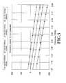
- FIG. 3shows a graphic representing phase progression for different positions of the phase shifter.
- FIG. 4shows examples of some possible embodiments of the small radiating elements for the antenna array.
- the radiating elementsare represented in perspective and housed within a box type ground-plane.
- the radiating elementsare shown in a plan view.
- FIG. 5shows in figures (a), (b) and (c) perspective views of examples of the arrangement of interleaving radiating elements working at different frequencies.
- Figure (d)is a schematic plan view of the interlaced disposition of the radiating elements. The position of each radiating element is represented by a square and the elements for a first frequency are shown in lighter shading, and the elements for a second frequency are shown in darker shading.
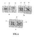
- FIG. 6shows in perspective more examples of interleaving radiating elements working at different frequencies according to the present invention.
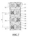
- FIG. 7shows a front view of the top portion of an antenna array, showing the arrangement of the radiating elements and its interlaced configuration.
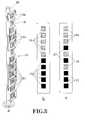
- FIG. 8shows in figure (a) a perspective view of a preferred arrangement of an antenna array showing the radiating elements and its stacked configuration.
- Figure (b)is an schematic front view of an example of the spatial arrangement of the stacked radiating elements working at different frequencies (elements for a first frequency shown in black boxes, elements for a second frequency shown in gridded boxes).
- Figure (c)is a schematic front view of an example of stacked radiating elements in which some elements are interlaced in the central portion of the array.
- FIG. 9shows a schematic cross-sectional views of a tri-sector antenna housed within a cylindrical radome.
- the three rectangular shapesrepresent the antenna arrays in a top view.
- Figure (a)shows three dualband antennas forming a tri-sector with 20 degrees of angular spacing.
- Figure (b)shows a tri-sector antenna without angular spacing, and figure (c) a tri-sector antenna with 20 degrees of angular spacing and ground-planes with bent flanges.
- FIG. 10shows a perspective view of slim stacked dual band antenna arrays mounted on a modular tower, in three different heights from the floor.
- FIG. 11shows an example of how the box-counting dimension is computed according to the present invention.
- FIG. 12shows an example of a curve featuring a grid-dimension larger than 1, also referred here as a ‘grid-dimension curve’.
- FIG. 13shows the curve of FIG. 12 in a 32-cell grid.
- FIG. 14shows the curve of FIG. 12 in a 128-cell grid.
- FIG. 15shows the curve of FIG. 12 in a 512-cell grid.
- the multiband antenna array of the inventioncomprises a first set of radiating elements ( 17 ) operating at a first frequency band and a second set of radiating elements ( 16 ) operating at a second frequency band.
- the radiating elements of this antenna systemare smaller than ⁇ /2 or smaller than ⁇ /3, being ( ⁇ ) the longest operating wavelength.
- FIG. 4shows a few examples of some possible radiating elements ( 13 ) that might be used within the scope of the present invention.
- the height of the radiating elements ( 13 ) with respect to the ground plane of the antennais also small, helping the integration of three dual band antennas on a slim cylinder. Such a height ( 13 ) is smaller than 0.15 wavelengths (0.15 ⁇ ) at the frequency of operation, but also smaller than 0.08 ⁇ in several embodiments.
- the radiating elements ( 13 ) placed on substrate ( 15 )are fed in four points ( 14 ) and the two ports with the same polarization are combined with a divider, resulting in an element with two ports, that exhibits orthogonal polarizations.
- These four feeding points ( 14 )can be feeding the radiating element ( 13 ) for instance by direct contact or by capacitive coupling.
- the capacitive couplingno electrical contact is required to connect the element, so solder joints or metal fasteners are avoided on the element. This can improve inter-modulation performance and it is one of the preferred arrangements of the invention.
- the aspect ratio of the elements(vertical:horizontal sizes) will be 1 to 1 (1:1), in some other preferred embodiments, a deviation smaller than a 15% in one of axes will be introduced in at least one of the elements to improve the polarization isolation, the isolation between connectors of different bands, or both.
- the radiating elements ( 13 ) of each multiband antenna arraymay be interlaced in different configurations.
- An example of the interlaced arrangement of the radiating elementsis shown in FIG. 5 .
- the radiating elements of a first frequency band ( 16 )are interlaced with the radiating elements of a second frequency band ( 17 ).
- all the radiating elementsare arranged in a matrix defined by two substantially parallel columns and a plurality of substantially parallel horizontal rows.
- each radiating element of one frequency bandis placed in between radiating elements of the other frequency band.
- two radiating elements of different frequency bandsare facing each other.
- each radiating element of one frequency bandis vertically and horizontally adjacent to radiating elements of the other frequency band.
- all the elements in the arrayare sequentially interlaced, while in other embodiments only a fraction of the elements are interlaced and some others remain on their respective side-by-side columns with no interlacing.
- FIGS. 5 a,b,cExamples of interleaving radiating elements working at different frequencies, are shown in FIGS. 5 a,b,c and in FIG. 6 .
- the horizontal separation between elementsis smaller than ⁇ /2, but bigger than ⁇ /3 to maintain the proper horizontal beamwidth ( ⁇ 75 degrees). It could be less than ⁇ /3 if broader horizontal beamwidth (>70 degrees) is required.
- a horizontal offset between bandsis also introduced in some embodiments to adjust horizontal beamwidth. This is for instance shown in FIG. 7 , where the horizontal spacing between interlaced elements ( 16 ) is smaller than the horizontal spacing between interlaced elements ( 17 ).
- FIG. 7shows a practical embodiment of a multiband antenna array in which the radiating elements ( 16 ),( 17 ) of the two frequency bands are interlaced as previously described.
- each radiating elementis mounted inside a box type ground plane ( 18 ), having side walls connected to a bottom base, whereas the top base is open, so that the radiating element is orthogonally placed with respect to the walls of the box type ground plane ( 18 ).
- the bottom baseacts as a ground plane for each radiating elements ( 16 ),( 17 ) while the side walls ( 18 ) enhance the isolation between radiating elements.
- this box ( 18 )can be made of metal casting or injection-moulded plastic covered with a conductor. So there is a possibility to manufacture this antenna without using an extruded or sheet metal ground plane. Also, for better isolation and cross polarization performance, each element should preferably have four feeding points ( 14 ) or more, preferably symmetrical, although unsymmetrical embodiments are allowed as well.
- the vertical spacing (d) between radiating elementshas been represented in FIG. 7 , where such spacing has been considered as an example between the centers of consecutive radiating elements of a first frequency band ( 17 ).
- Said vertical spacing (d)may be less than one ⁇ , but also preferably less than 3 ⁇ 4 of ⁇ and less than 2 ⁇ 3 of ⁇ at all frequencies of operation to maintain a good radiation pattern.
- a Filter/Diplexeris added inside the antenna to achieve greater isolation between electrical ports of different frequency bands.
- the radiating elementsmay be arranged in a stacked topology also in order to reduce the size of the antenna array.
- An example of the spatial arrangement of the stacked radiating elements working at different frequenciesis shown in FIG. 8 .
- Squared elementsare shown in FIG. 8 b to illustrate the positions of the elements in the array according to the present invention.
- other shapes of elementsfor instance space-filling, fractal, multilevel, straight, triangle, circular, polygonal
- antenna topologiesfor instance patches, dipoles, slots
- All the radiating elementsare aligned in a single column, wherein the elements of a first frequency band ( 17 ) are grouped together in the column below the elements of a second frequency band ( 16 ) which are grouped at the top portion of the column.
- the second frequency bandis the highest frequency one to reduce the gain difference between bands.
- the highest frequency elementsare preferably placed in the lower section of the stack.
- the number of radiating elements at each of the two regions for each banddoes not need to be the same. Different number of elements will be preferably used in those cases where a different radiation pattern for each band is desired.
- the spacing between elementswill preferably be between 0.6 ⁇ and 1.2 ⁇ at the shortest operating band within each corresponding region. For instance, in some embodiments the physical distance between elements in a first frequency region will be different than the physical distance between elements in a second frequency region, but the electrical distance (in terms of their corresponding operating frequencies) will be substantially similar.
- FIG. 8 aA preferred embodiment with stacked configuration of the radiating elements is shown in FIG. 8 a , wherein each radiating element is located within a box-like ground plane ( 18 ).
- the vertical separation between stacked arraysis larger than ⁇ , such distance is modified to control the gain adding more elements.
- ⁇the vertical separation between stacked arrays (centre to centre of each group of elements corresponding to a band) is larger than ⁇ , such distance is modified to control the gain adding more elements.
- FIG. 8 cit is possible to interlace some elements of a first frequency ( 17 ) with some elements of a second frequency ( 16 ) to modify the radiation pattern and gain of the antenna.
- flanges ( 29 )between elements.
- the flanges ( 29 )will be placed between every single radiating element and will have the same shape.
- further improvement of the polarization isolationis achieved by using asymmetrical arrangements and distributions of flanges ( 29 ) between radiating elements, as shown for instance in FIG. 5 b.
- a preferred embodiment of the inventioncomprises two additional antenna arrays to form a tri-sector antenna. Therefore, one of the main advantages of the present invention is that it is possible to integrate three dual band antennas in a slim cylinder, forming a tri-sector antenna.
- a single cylinder radome ( 22 )can be used. This technique is used to reduce visual impact by Base Station Antenna Manufacturers.
- the diameter of the circumference formed by the three antennasis less than 2 ⁇ at the greater frequency of each band, and even less than 1.5 ⁇ . This is achieved because of the compact size and architecture of each Dual Band antenna.
- the number of radiating elements around the central support ( 28 )will be just two, while in some other embodiments this number will be larger than three, preferably 4, 5 or 6.
- an angular spacingis introduced between antennas, and a mechanical feature is added in order to adjust the horizontal boresight of each sector so optimising the azimuth coverage.
- the diameter of the total circumference formed by the three antennasis still less than 2 ⁇ , and even less than 1.82 ⁇ at the highest frequency, with an angular spacing of at least 20 degrees. Smaller diameter is achieved in some embodiments by reducing the angular spacing and/or its adjustment range.
- the antenna arrays ( 19 , 19 ′, 19 ′′)are radially spaced from a central axis ( 21 ) of the antenna system.
- Each antenna array ( 19 , 19 ′, 19 ′′)is respectively placed longitudinally within an angular sector ( 20 , 20 ′, 20 ′′) defined around said central axis ( 21 ), the antenna arrays ( 19 , 19 ′, 19 ′′) being substantially parallel to said central axis ( 21 ).
- the three antenna arrays ( 19 , 19 ′, 19 ′′)are housed within a substantially cylindrical radome ( 22 ), which is preferably made of dielectric material and is substantially transparent within the 1700-2700 MHz frequency range. As shown in FIG. 9 , each array is placed according to the position of the sides of an equilateral triangle, which center is the axis ( 21 ) of the antenna system.
- the central support ( 28 )is aligned with respect said axis ( 21 ), and the antenna arrays ( 19 , 19 ′, 19 ′′) are mounted on said central support ( 28 ) at a selected distance.
- the three angular sectors ( 20 , 20 ′, 20 ′′)are less than 120° so that an angular spacing (A) is defined between said angular sectors.
- said angular spacing (A)is within the range 0° to 30°.
- the diameter of the cylindrical radome ( 22 )is reduced with respect to the embodiment of FIG. 9 a , for which the three angular sectors ( 20 , 20 ′, 20 ′′) extend 120° so that there is no angular spacing (A) in between.
- the antenna arrays ( 19 , 19 ′, 19 ′′)may be in contact at their sides.
- FIG. 9 cis an example of a Tri-Band antenna with three independent down-tilt and an angular spacing of 20 degrees.
- the ground plane profile23 , 23 ′, 23 ′′
- has flanges24 , 24 ′, 24 ′′ bent upwards at the optimum angle for minimizing antenna diameter and maximizing aperture of radiation, which is 40 degrees in this example.
- Each multiband antenna arrayis provided with a phase shifter device providing an adjustable electrical downtilt for each frequency band.
- the phase shifterincludes an electrical path of variable length, for which the phase shifter preferably comprises a first transmission line slideably mounted on a second transmission line.
- FIG. 1refers to the phase shifter shown in FIG. 1 , which in a preferred embodiment is formed by a moveable line ( 1 ) mounted on a fixed main transmission line ( 3 ).
- the movable line ( 1 )has a “U” shape, but could have another shape featuring two transmission line ends ( 2 , 2 ′) that move together over such main transmission line ( 3 ).
- the movable line ( 1 )will have two parallel ends ( 2 , 2 ′) that overlap an interrupted region of the fixed main transmission line ( 3 ), such that a linear displacement of said movable line ( 1 ) introduces a longer electrical path on a whole transmission line set.
- FIG. 1shows a moveable line ( 1 ) mounted on a fixed main transmission line ( 3 ).
- the movable line ( 1 )has a “U” shape, but could have another shape featuring two transmission line ends ( 2 , 2 ′) that move together over such main transmission line ( 3 ).
- the movable line ( 1 )will
- the moveable line ( 1 )is formed by a first substrate ( 7 ) provided with a first conductive layer ( 6 ), and the fixed main transmission line ( 3 ) is similarly formed by a second substrate ( 9 ) and a second conductive layer ( 8 ) on one of its faces.
- the moveable line ( 1 )slides above the main transmission line ( 3 ) and both are separated by respective low friction layers ( 30 ),( 30 ′) of a low microwave loss material, which could be for instance a Teflon base, to increase durability and avoid passive intermodulation (PIMs) at the same time. All parts are sandwiched together with a flexible bridge ( 5 ) that acts as a spring to avoid air gaps between layers and so maintaining the proper phase shifting.
- the bridge ( 5 )is formed by a base ( 12 ) fixed for instance to a support ( 31 ) of the main transmission line ( 3 ).
- a flexible arm ( 10 )projects horizontally from said base ( 12 ) and forms a protuberance ( 11 ) at its free end which maintains the moveable line ( 1 ) in contact with the main transmission line ( 3 ) during its displacement.
- the bridge ( 5 )acts as a spring due to its shape and the plastic material used.
- this plastic materialcan be chosen, without any limiting purpose, from the following set: Polypropylene, Acetal, PVC, and Nylon. This part can be moulded for manufacturability and low cost.
- the electrical length of the phase shiftermay be adjusted either manually or by means of a small electric motor (not shown), which in turn may be remotely controlled by means of any technique known to the prior art.
- the antenna systemis mounted on an elongated tower or support ( 25 ) of adjustable height and preferably of cylindrical shape.
- the supportmay be formed by one or more modular support sections ( 26 ) axially coupled together, by means of any technique known in the state of the art suitable for this purpose.
- the support ( 25 )may comprises hinge means at its bottom end so that the support ( 25 ) can be bent to make easier its installation and maintenance.
- the support sectorsmay form a telescopic structure, and the support ( 25 ) can be retracted.
- a way of miniaturizing the radiating elements of the Multiband Arrayis shaping part of the antenna elements (for example at least a part of the arms of a dipole, the perimeter of the patch of a patch antenna, the slot in a slot antenna, the loop perimeter in a loop antenna) as a space-filling curve (SFC), i.e., a curve that is large in terms of physical length but small in terms of the area in which the curve can be included. More precisely, the following definition is taken in this invention for a space-filling curve: a curve composed by at least five segments which are connected in such a way that each segment forms an angle with their neighbours, i.e., no pair of adjacent segments define a larger straight segment.
- SFCspace-filling curve
- a SFCcan comprise straight segments, and in some other embodiments a SFC can comprise curved segments, and yet in other cases a SFC can comprise both straight and curved segments. Also, whatever the design of such SFC is, it can never intersect with itself at any point except the initial and final point (that is, the whole curve can be arranged as a closed curve or loop, but none of the parts of the curve can become a closed loop).
- a space-filling curvecan be fitted over a flat or curved surface, and due to the angles between segments, the physical length of the curve is always larger than that of any straight line that can be fitted in the same area (surface) as said space-filling curve.
- the segments of the SFC curvesmust be shorter than at least one fifth of the free-space operating wavelength, in some embodiments preferably shorter than one tenth of the free-space operating wavelength.
- fiveis the minimum number of segments to provide some antenna size reduction, in some embodiments a larger number of segments can be chosen, for instance 10, 20 or more. In general, the larger the number of segments and the narrower the angles between them, the smaller the size of the final antenna.
- One aspect of the present inventionis the box-counting dimension of the curve that forms at least a portion of the antenna.
- the box-counting dimensionis computed in the following way: first a grid with substantially squared identical cells boxes of size L 1 is placed over the geometry, such that the grid completely covers the geometry, that is, no part of the curve is out of the grid. Then the number of boxes N 1 that include at least a point of the geometry are counted; secondly a grid with boxes of size L 2 (L 2 being smaller than L 1 ) is also placed over the geometry, such that the grid completely covers the geometry, and the number of boxes N 2 that include at least a point of the geometry are counted again.
- the box-counting dimension Dis then computed as:
- the box-counting dimensionis computed by placing the first and second grids inside the minimum rectangular area enclosing the curve of the antenna and applying the above algorithm.
- the minimum rectangular areait will be understood such area wherein there is not an entire row or column on the perimeter of the grid that does not contain any piece of the curve.
- some of the embodiments of the present inventionwill feature a box-counting dimension larger than 1.1, and in those applications where the required degree of miniaturization is higher, the designs will feature a box-counting dimension ranging from 1.3 up to 3, inclusive.
- a curve having a box-counting dimension close to 2is preferred.
- the box-counting dimensionwill be necessarily computed with a finer grid.
- the first gridwill be taken as a mesh of 10 ⁇ 10 equal cells, while the second grid will be taken as a mesh of 20 ⁇ 20 equal cells, and then D is computed according to the equation above.
- the larger the box-counting dimensionthe higher the degree of miniaturization that will be achieved by the antenna.
- One way of enhancing the miniaturization capabilities of the antenna according to the present inventionis to arrange the several segments of the curve of the antenna pattern in such a way that the curve intersects at least one point of at least 14 boxes of the first grid with 5 ⁇ 5 boxes or cells enclosing the curve. Also, in other embodiments where a high degree of miniaturization is required, the curve crosses at least one of the boxes twice within the 5 ⁇ 5 grid, that is, the curve includes two non-adjacent portions inside at least one of the cells or boxes of the grid.
- FIG. 11An example of how the box-counting dimension is computed according to the present invention is shown in FIG. 11 .
- An example of a curve ( 2300 ) according to the present inventionis placed under a 5 ⁇ 5 grid ( 2301 ) and under a 10 ⁇ 10 grid ( 2302 ).
- the size of the boxes in grid ( 2301 )is twice the size of the boxes in ( 2302 ).
- the curve ( 2300 )crosses more than 14 of the 25 boxes in grid ( 2301 ), and also the curve crosses at least one box twice, that is, at least one box contains two non-adjacent segments of the curve. In fact, ( 2300 ) is an example where such a double crossing occurs in 13 boxes out of the 25 in ( 2301 ).
- the radiating elements of the Multi Band Array of the present inventioninclude a characteristic grid dimension curve forming at least a portion of the at least one radiating element of the antenna.
- a grid dimension curvedoes not need to show clearly distinct segments and can be a completely smooth curve.
- the grid dimension in a grid dimension curveis computed in the following way:
- a grid with substantially identical cells of size L 1is placed over the geometry of said curve, such that the grid completely covers the geometry, and the number of cells N 1 that include at least a point of the geometry are counted;
- a grid with cells of size L 2is also placed over the geometry, such that the grid completely covers the geometry, and the number of cells N 2 that include at least a point of the geometry are counted again.
- the grid dimension Dis then computed as:
- the grid dimensionis computed by placing the first and second grids inside the minimum rectangular area enclosing the curve of the antenna and applying the above algorithm.
- minimum rectangular areait will be understood such area wherein there is not an entire row or column on the perimeter of the grid that does not contain any piece of the curve.
- some of the embodiments of the present inventionwill feature a grid dimension larger than 1, and in those applications where the required degree of miniaturization is higher, the designs will feature a grid dimension ranging from 1.5 up to 3 (in case of volumetric structures), inclusive.
- a curve having a grid dimension of about 2is preferred. In any case, for the purpose of the present invention, a grid dimension curve will feature a grid dimension larger than 1.
- One way of enhancing the miniaturization capabilities of the antenna according to the present inventionis to arrange the several segments of the curve of the antenna pattern in such a way that the curve intersects at least one point of at least 50% of the cells of the first grid with at least 25 cells enclosing the curve.
- the curvecrosses at least one of the cells twice within the 25 cell grid, that is, the curve includes two non-adjacent portions inside at least one of the cells or cells of the grid.
- FIG. 12shows an example of a curve featuring a grid-dimension larger than 1, also referred here as a ‘grid-dimension curve’.
- the curve of FIG. 12is in a 512-cell grid.
- the curvecrosses 509 cells at least at one point of the cell.
- the elements in the arraywill be patch antenna elements, having a perimeter or at least one portion of the element structure shaped with a curve of at least 5 segments, being said segments smaller than the longest operating wavelength ( ⁇ ) divided by 5.
- a curvewill feature a box-counting dimension or a grid dimension larger than 1.1, typical above 1.2 or 1.3.
- itwill feature a grid-dimension preferably larger than 1.1, typical above 1.2 or 1.3 as well.
- the larger the box counting or grid-dimensionthe smaller the size of the radiating element.
- the present inventionconsists of an antenna whose radiating element is characterised by its geometrical shape, which basically comprises several polygons or polyhedrons of the same type. That is, it comprises for example triangles, squares, pentagons, hexagons or even circles and ellipses as a limiting case of a polygon with a large number of sides, as well as tetrahedral, hexahedra, prisms, dodecahedra, etc. coupled to each other electrically (either through at least one point of contact or through a small separation providing a capacitive coupling) and grouped in structures of a higher level such that in the body of the antenna can be identified the polygonal or polyhedral elements which it comprises.
- structures generated in this mannercan be grouped in higher order structures in a manner similar to the basic elements, and so on until reaching as many levels as the antenna designer desires.
- a multilevel structureis characterized in that it is formed by gathering several polygon or polyhedron of the same type (for example triangles, parallelepipeds, pentagons, hexagons, etc., even circles or ellipses as special limiting cases of a polygon with a large number of sides, as well as tetrahedral, hexahedra, prisms, dodecahedra, etc.) coupled to each other electromagnetically, whether by proximity or by direct contact between elements.
- a multilevel structure or figureis distinguished from another conventional figure precisely by the interconnection (if it exists) between its component elements (the polygon or polyhedron).
- a multilevel structureIn a multilevel structure the majority of its component elements (in some embodiments preferably at least 75% of them) have more than 50% of their perimeter (for polygons) not in contact with any of the other elements of the structure. Thus, in a multilevel structure it is easy to identify geometrically and individually distinguish most of its basic component elements, presenting at least two levels of detail: that of the overall structure and that of the polygon or polyhedron elements which form it. Its name is precisely due to this characteristic and from the fact that the polygon or polyhedron can be included in a great variety of sizes. Additionally, several multilevel structures may be grouped and coupled electromagnetically to each other to form higher level structures. In a multilevel structure all the component elements are polygons with the same number of sides or polyhedron with the same number of faces. Naturally, this property is broken when several multilevel structures of different natures are grouped and electromagnetically coupled to form meta-structures of a higher level.
- multilevel antennaIts designation as multilevel antenna is precisely due to the fact that in the body of the antenna can be identified at least two levels of detail: that of the overall structure and that of the majority of the elements (polygons or polyhedrons) which make it up. This is achieved by ensuring that the area of contact or intersection (if it exists) between the majority of the elements forming the antenna is only a fraction of the perimeter or surrounding area of said polygons or polyhedrons.
- a particular property of multilevel antennaeis that their radioelectric behaviour can be similar in several frequency bands.
- Antenna input parametersimpedance and radiation pattern
- the antennahas the same level of matching or standing wave relationship in each different band
- the antennapresents almost identical radiation diagrams at different frequencies. This is due precisely to the multilevel structure of the antenna, that is, to the fact that it remains possible to identify in the antenna the majority of basic elements (same type polygons or polyhedrons) which make it up.
- the number of frequency bandsis proportional to the number of scales or sizes of the polygonal elements or similar sets in which they are grouped contained in the geometry of the main radiating element.
- multilevel structure antennaeIn addition to their multiband behaviour, multilevel structure antennae usually have a smaller than usual size as compared to other antennae of a simpler structure. (Such as those consisting of a single polygon or polyhedron). Additionally, its edge-rich and discontinuity-rich structure enhances the radiation process, relatively increasing the radiation resistance of the antenna and reducing the quality factor Q, i.e. increasing its bandwidth.
- the main characteristic of multilevel antennaeare the following:
- Multilevel antennaebase their behaviour on their particular geometry, offering a greater flexibility to the antenna designer as to the number of bands (proportional to the number of levels of detail), position, relative spacing and width, and thereby offer better and more varied characteristics for the final product.
- a multilevel structurecan be used in any known antenna configuration. As a non-limiting example can be cited: dipoles, monopoles, patch or microstrip antennae, coplanar antennae, reflector antennae, wound antennae or even antenna arrays. Manufacturing techniques are also not characteristic of multilevel antennae as the best-suited technique may be used for each structure or application. For example: printing on dielectric substrate by photolithography (printed circuit technique); dieing on metal plate, repulsion on dielectric, etc.
Landscapes
- Engineering & Computer Science (AREA)
- Computer Networks & Wireless Communication (AREA)
- Physics & Mathematics (AREA)
- Electromagnetism (AREA)
- Variable-Direction Aerials And Aerial Arrays (AREA)
Abstract
Description
- having the smallest radome diameter for lower visual impact and lower windload, allowing the mimetization of the radiating part of the base station with the environment,
- having the biggest angular spacing for more flexibility in optimising the azimuth coverage of each sector,
- having the maximum horizontal radiation aperture to increase the directivity of the antenna in the horizontal plane.
α=30+A/2
where (α) is the angle between the horizontal and the flanges of the ground plane and (A) is the angular spacing between 2 antennas.
- A multilevel geometry comprising polygon or polyhedron of the same class, electromagnetically coupled and grouped to form a larger structure. In multilevel geometry most of these elements are clearly visible as their area of contact, intersection or interconnection (if these exist) with other elements is always less than 50% of their perimeter.
- The radioelectric behaviour resulting from the geometry: multilevel antennae can present a multiband behaviour (identical or similar for several frequency bands) and/or operate at a reduced frequency, which allows reducing their size.
Claims (42)
Priority Applications (1)
| Application Number | Priority Date | Filing Date | Title |
|---|---|---|---|
| US11/660,802US7868843B2 (en) | 2004-08-31 | 2005-08-31 | Slim multi-band antenna array for cellular base stations |
Applications Claiming Priority (7)
| Application Number | Priority Date | Filing Date | Title |
|---|---|---|---|
| US60603804P | 2004-08-31 | 2004-08-31 | |
| EP05103226.6 | 2005-04-21 | ||
| EP05103226 | 2005-04-21 | ||
| EP05103226 | 2005-04-21 | ||
| US67856905P | 2005-05-06 | 2005-05-06 | |
| PCT/EP2005/009376WO2006024516A1 (en) | 2004-08-31 | 2005-08-31 | Slim multi-band antenna array for cellular base stations |
| US11/660,802US7868843B2 (en) | 2004-08-31 | 2005-08-31 | Slim multi-band antenna array for cellular base stations |
Publications (2)
| Publication Number | Publication Date |
|---|---|
| US20080062062A1 US20080062062A1 (en) | 2008-03-13 |
| US7868843B2true US7868843B2 (en) | 2011-01-11 |
Family
ID=35169643
Family Applications (1)
| Application Number | Title | Priority Date | Filing Date |
|---|---|---|---|
| US11/660,802Expired - Fee RelatedUS7868843B2 (en) | 2004-08-31 | 2005-08-31 | Slim multi-band antenna array for cellular base stations |
Country Status (3)
| Country | Link |
|---|---|
| US (1) | US7868843B2 (en) |
| EP (1) | EP1784894A1 (en) |
| WO (1) | WO2006024516A1 (en) |
Cited By (13)
| Publication number | Priority date | Publication date | Assignee | Title |
|---|---|---|---|---|
| US20100265150A1 (en)* | 2009-04-17 | 2010-10-21 | Per-Anders Arvidsson | Antenna Assembly |
| US20120050126A1 (en)* | 2010-08-31 | 2012-03-01 | Ace Technologies Corp. | Patch antenna synchronously generating linearly polarized wave and circularly polarized wave and generating method thereof |
| US20130225222A1 (en)* | 2012-02-24 | 2013-08-29 | Futurewei Technologies, Inc. | Apparatus and Method for Modular Multi-Sector Active Antenna System |
| US8754824B2 (en)* | 2005-10-14 | 2014-06-17 | Fractus, S.A. | Slim triple band antenna array for cellular base stations |
| US20140168027A1 (en)* | 2012-12-14 | 2014-06-19 | Raja Reddy KATIPALLY | Broadband In-Line Antenna Systems And Related Methods |
| US9130271B2 (en) | 2012-02-24 | 2015-09-08 | Futurewei Technologies, Inc. | Apparatus and method for an active antenna system with near-field radio frequency probes |
| US9231299B2 (en) | 2012-10-25 | 2016-01-05 | Raytheon Company | Multi-bandpass, dual-polarization radome with compressed grid |
| US20160126614A1 (en)* | 2014-10-29 | 2016-05-05 | Samsung Electronics Co., Ltd. | Antenna Device and Electronic Device Having the Same |
| US9362615B2 (en) | 2012-10-25 | 2016-06-07 | Raytheon Company | Multi-bandpass, dual-polarization radome with embedded gridded structures |
| US20170033471A1 (en)* | 2015-07-30 | 2017-02-02 | Wistron Neweb Corp. | Antenna System |
| WO2020094219A1 (en)* | 2018-11-07 | 2020-05-14 | Huawei Technologies Co., Ltd. | Antenna and base station |
| US10720714B1 (en)* | 2013-03-04 | 2020-07-21 | Ethertronics, Inc. | Beam shaping techniques for wideband antenna |
| US20230017375A1 (en)* | 2019-12-24 | 2023-01-19 | Commscope Technologies Llc | Radiating element, antenna assembly and base station antenna |
Families Citing this family (230)
| Publication number | Priority date | Publication date | Assignee | Title |
|---|---|---|---|---|
| US7868843B2 (en) | 2004-08-31 | 2011-01-11 | Fractus, S.A. | Slim multi-band antenna array for cellular base stations |
| US7642988B1 (en) | 2006-06-19 | 2010-01-05 | Sprint Communications Company L.P. | Multi-link antenna array configured for cellular site placement |
| US7881752B1 (en)* | 2006-06-19 | 2011-02-01 | Sprint Communications Company L.P. | Hybrid architecture that combines a metropolitan-area network fiber system with a multi-link antenna array |
| GB2439975B (en)* | 2006-07-07 | 2010-02-24 | Iti Scotland Ltd | Antenna arrangement |
| GB0622435D0 (en)* | 2006-11-10 | 2006-12-20 | Quintel Technology Ltd | Electrically tilted antenna system with polarisation diversity |
| US8354972B2 (en) | 2007-06-06 | 2013-01-15 | Fractus, S.A. | Dual-polarized radiating element, dual-band dual-polarized antenna assembly and dual-polarized antenna array |
| US8502743B2 (en) | 2007-12-05 | 2013-08-06 | Cricket Communications, Inc. | Single port dual antenna |
| DE102008041651A1 (en)* | 2008-08-28 | 2010-03-04 | Robert Bosch Gmbh | electrical appliance |
| US8466843B1 (en)* | 2009-03-19 | 2013-06-18 | Rockwell Collins, Inc. | Integrated L/C/Ku band antenna with omni-directional coverage |
| WO2011026034A2 (en)* | 2009-08-31 | 2011-03-03 | Andrew Llc | Modular type cellular antenna assembly |
| US8604997B1 (en)* | 2010-06-02 | 2013-12-10 | Lockheed Martin Corporation | Vertical array antenna |
| US20130294302A1 (en)* | 2010-08-04 | 2013-11-07 | Nokia Siemens Networks Oy | Broadband Antenna and Radio Base Station System for Process-ing at Least Two Frequency Bands or Radio Standards in a Radio Communications System |
| US9882430B1 (en) | 2014-05-07 | 2018-01-30 | Energous Corporation | Cluster management of transmitters in a wireless power transmission system |
| US10211680B2 (en) | 2013-07-19 | 2019-02-19 | Energous Corporation | Method for 3 dimensional pocket-forming |
| US9867062B1 (en) | 2014-07-21 | 2018-01-09 | Energous Corporation | System and methods for using a remote server to authorize a receiving device that has requested wireless power and to determine whether another receiving device should request wireless power in a wireless power transmission system |
| US10008889B2 (en) | 2014-08-21 | 2018-06-26 | Energous Corporation | Method for automatically testing the operational status of a wireless power receiver in a wireless power transmission system |
| US10199835B2 (en) | 2015-12-29 | 2019-02-05 | Energous Corporation | Radar motion detection using stepped frequency in wireless power transmission system |
| US20150326070A1 (en) | 2014-05-07 | 2015-11-12 | Energous Corporation | Methods and Systems for Maximum Power Point Transfer in Receivers |
| US9954374B1 (en) | 2014-05-23 | 2018-04-24 | Energous Corporation | System and method for self-system analysis for detecting a fault in a wireless power transmission Network |
| US9838083B2 (en) | 2014-07-21 | 2017-12-05 | Energous Corporation | Systems and methods for communication with remote management systems |
| US10063064B1 (en) | 2014-05-23 | 2018-08-28 | Energous Corporation | System and method for generating a power receiver identifier in a wireless power network |
| US9876648B2 (en) | 2014-08-21 | 2018-01-23 | Energous Corporation | System and method to control a wireless power transmission system by configuration of wireless power transmission control parameters |
| US10193396B1 (en) | 2014-05-07 | 2019-01-29 | Energous Corporation | Cluster management of transmitters in a wireless power transmission system |
| US10211674B1 (en) | 2013-06-12 | 2019-02-19 | Energous Corporation | Wireless charging using selected reflectors |
| US9843213B2 (en) | 2013-08-06 | 2017-12-12 | Energous Corporation | Social power sharing for mobile devices based on pocket-forming |
| US9859797B1 (en) | 2014-05-07 | 2018-01-02 | Energous Corporation | Synchronous rectifier design for wireless power receiver |
| US9793758B2 (en) | 2014-05-23 | 2017-10-17 | Energous Corporation | Enhanced transmitter using frequency control for wireless power transmission |
| US9871398B1 (en) | 2013-07-01 | 2018-01-16 | Energous Corporation | Hybrid charging method for wireless power transmission based on pocket-forming |
| US9893768B2 (en) | 2012-07-06 | 2018-02-13 | Energous Corporation | Methodology for multiple pocket-forming |
| US9991741B1 (en) | 2014-07-14 | 2018-06-05 | Energous Corporation | System for tracking and reporting status and usage information in a wireless power management system |
| US9900057B2 (en) | 2012-07-06 | 2018-02-20 | Energous Corporation | Systems and methods for assigning groups of antenas of a wireless power transmitter to different wireless power receivers, and determining effective phases to use for wirelessly transmitting power using the assigned groups of antennas |
| US11502551B2 (en) | 2012-07-06 | 2022-11-15 | Energous Corporation | Wirelessly charging multiple wireless-power receivers using different subsets of an antenna array to focus energy at different locations |
| US9450449B1 (en)* | 2012-07-06 | 2016-09-20 | Energous Corporation | Antenna arrangement for pocket-forming |
| US10141791B2 (en) | 2014-05-07 | 2018-11-27 | Energous Corporation | Systems and methods for controlling communications during wireless transmission of power using application programming interfaces |
| US9143000B2 (en) | 2012-07-06 | 2015-09-22 | Energous Corporation | Portable wireless charging pad |
| US10291055B1 (en) | 2014-12-29 | 2019-05-14 | Energous Corporation | Systems and methods for controlling far-field wireless power transmission based on battery power levels of a receiving device |
| US10256657B2 (en) | 2015-12-24 | 2019-04-09 | Energous Corporation | Antenna having coaxial structure for near field wireless power charging |
| US10263432B1 (en) | 2013-06-25 | 2019-04-16 | Energous Corporation | Multi-mode transmitter with an antenna array for delivering wireless power and providing Wi-Fi access |
| US10090886B1 (en) | 2014-07-14 | 2018-10-02 | Energous Corporation | System and method for enabling automatic charging schedules in a wireless power network to one or more devices |
| US9973021B2 (en) | 2012-07-06 | 2018-05-15 | Energous Corporation | Receivers for wireless power transmission |
| US20140008993A1 (en) | 2012-07-06 | 2014-01-09 | DvineWave Inc. | Methodology for pocket-forming |
| US10992187B2 (en) | 2012-07-06 | 2021-04-27 | Energous Corporation | System and methods of using electromagnetic waves to wirelessly deliver power to electronic devices |
| US10199849B1 (en) | 2014-08-21 | 2019-02-05 | Energous Corporation | Method for automatically testing the operational status of a wireless power receiver in a wireless power transmission system |
| US9912199B2 (en) | 2012-07-06 | 2018-03-06 | Energous Corporation | Receivers for wireless power transmission |
| US10063105B2 (en) | 2013-07-11 | 2018-08-28 | Energous Corporation | Proximity transmitters for wireless power charging systems |
| US9876379B1 (en) | 2013-07-11 | 2018-01-23 | Energous Corporation | Wireless charging and powering of electronic devices in a vehicle |
| US9923386B1 (en) | 2012-07-06 | 2018-03-20 | Energous Corporation | Systems and methods for wireless power transmission by modifying a number of antenna elements used to transmit power waves to a receiver |
| US9843201B1 (en)* | 2012-07-06 | 2017-12-12 | Energous Corporation | Wireless power transmitter that selects antenna sets for transmitting wireless power to a receiver based on location of the receiver, and methods of use thereof |
| US9899873B2 (en) | 2014-05-23 | 2018-02-20 | Energous Corporation | System and method for generating a power receiver identifier in a wireless power network |
| US9831718B2 (en) | 2013-07-25 | 2017-11-28 | Energous Corporation | TV with integrated wireless power transmitter |
| US9824815B2 (en) | 2013-05-10 | 2017-11-21 | Energous Corporation | Wireless charging and powering of healthcare gadgets and sensors |
| US10224758B2 (en) | 2013-05-10 | 2019-03-05 | Energous Corporation | Wireless powering of electronic devices with selective delivery range |
| US9438045B1 (en) | 2013-05-10 | 2016-09-06 | Energous Corporation | Methods and systems for maximum power point transfer in receivers |
| US9787103B1 (en) | 2013-08-06 | 2017-10-10 | Energous Corporation | Systems and methods for wirelessly delivering power to electronic devices that are unable to communicate with a transmitter |
| US9893555B1 (en) | 2013-10-10 | 2018-02-13 | Energous Corporation | Wireless charging of tools using a toolbox transmitter |
| US10312715B2 (en) | 2015-09-16 | 2019-06-04 | Energous Corporation | Systems and methods for wireless power charging |
| US9124125B2 (en) | 2013-05-10 | 2015-09-01 | Energous Corporation | Wireless power transmission with selective range |
| US10124754B1 (en) | 2013-07-19 | 2018-11-13 | Energous Corporation | Wireless charging and powering of electronic sensors in a vehicle |
| US10075008B1 (en) | 2014-07-14 | 2018-09-11 | Energous Corporation | Systems and methods for manually adjusting when receiving electronic devices are scheduled to receive wirelessly delivered power from a wireless power transmitter in a wireless power network |
| US10128699B2 (en) | 2014-07-14 | 2018-11-13 | Energous Corporation | Systems and methods of providing wireless power using receiver device sensor inputs |
| US10965164B2 (en) | 2012-07-06 | 2021-03-30 | Energous Corporation | Systems and methods of wirelessly delivering power to a receiver device |
| US9948135B2 (en) | 2015-09-22 | 2018-04-17 | Energous Corporation | Systems and methods for identifying sensitive objects in a wireless charging transmission field |
| US9847679B2 (en) | 2014-05-07 | 2017-12-19 | Energous Corporation | System and method for controlling communication between wireless power transmitter managers |
| US10050462B1 (en) | 2013-08-06 | 2018-08-14 | Energous Corporation | Social power sharing for mobile devices based on pocket-forming |
| US10230266B1 (en) | 2014-02-06 | 2019-03-12 | Energous Corporation | Wireless power receivers that communicate status data indicating wireless power transmission effectiveness with a transmitter using a built-in communications component of a mobile device, and methods of use thereof |
| US10223717B1 (en) | 2014-05-23 | 2019-03-05 | Energous Corporation | Systems and methods for payment-based authorization of wireless power transmission service |
| US9887739B2 (en) | 2012-07-06 | 2018-02-06 | Energous Corporation | Systems and methods for wireless power transmission by comparing voltage levels associated with power waves transmitted by antennas of a plurality of antennas of a transmitter to determine appropriate phase adjustments for the power waves |
| US9939864B1 (en) | 2014-08-21 | 2018-04-10 | Energous Corporation | System and method to control a wireless power transmission system by configuration of wireless power transmission control parameters |
| US10186913B2 (en) | 2012-07-06 | 2019-01-22 | Energous Corporation | System and methods for pocket-forming based on constructive and destructive interferences to power one or more wireless power receivers using a wireless power transmitter including a plurality of antennas |
| US10270261B2 (en) | 2015-09-16 | 2019-04-23 | Energous Corporation | Systems and methods of object detection in wireless power charging systems |
| US9853692B1 (en) | 2014-05-23 | 2017-12-26 | Energous Corporation | Systems and methods for wireless power transmission |
| US10063106B2 (en) | 2014-05-23 | 2018-08-28 | Energous Corporation | System and method for a self-system analysis in a wireless power transmission network |
| US9876394B1 (en) | 2014-05-07 | 2018-01-23 | Energous Corporation | Boost-charger-boost system for enhanced power delivery |
| US10206185B2 (en) | 2013-05-10 | 2019-02-12 | Energous Corporation | System and methods for wireless power transmission to an electronic device in accordance with user-defined restrictions |
| US9887584B1 (en) | 2014-08-21 | 2018-02-06 | Energous Corporation | Systems and methods for a configuration web service to provide configuration of a wireless power transmitter within a wireless power transmission system |
| US9882427B2 (en) | 2013-05-10 | 2018-01-30 | Energous Corporation | Wireless power delivery using a base station to control operations of a plurality of wireless power transmitters |
| US9899861B1 (en) | 2013-10-10 | 2018-02-20 | Energous Corporation | Wireless charging methods and systems for game controllers, based on pocket-forming |
| US9891669B2 (en) | 2014-08-21 | 2018-02-13 | Energous Corporation | Systems and methods for a configuration web service to provide configuration of a wireless power transmitter within a wireless power transmission system |
| US9893554B2 (en) | 2014-07-14 | 2018-02-13 | Energous Corporation | System and method for providing health safety in a wireless power transmission system |
| US10141768B2 (en) | 2013-06-03 | 2018-11-27 | Energous Corporation | Systems and methods for maximizing wireless power transfer efficiency by instructing a user to change a receiver device's position |
| US9966765B1 (en) | 2013-06-25 | 2018-05-08 | Energous Corporation | Multi-mode transmitter |
| US9847677B1 (en) | 2013-10-10 | 2017-12-19 | Energous Corporation | Wireless charging and powering of healthcare gadgets and sensors |
| US10090699B1 (en) | 2013-11-01 | 2018-10-02 | Energous Corporation | Wireless powered house |
| US10103582B2 (en) | 2012-07-06 | 2018-10-16 | Energous Corporation | Transmitters for wireless power transmission |
| US10381880B2 (en) | 2014-07-21 | 2019-08-13 | Energous Corporation | Integrated antenna structure arrays for wireless power transmission |
| US10211682B2 (en) | 2014-05-07 | 2019-02-19 | Energous Corporation | Systems and methods for controlling operation of a transmitter of a wireless power network based on user instructions received from an authenticated computing device powered or charged by a receiver of the wireless power network |
| US10291066B1 (en) | 2014-05-07 | 2019-05-14 | Energous Corporation | Power transmission control systems and methods |
| US10243414B1 (en) | 2014-05-07 | 2019-03-26 | Energous Corporation | Wearable device with wireless power and payload receiver |
| US9941707B1 (en) | 2013-07-19 | 2018-04-10 | Energous Corporation | Home base station for multiple room coverage with multiple transmitters |
| US9941747B2 (en) | 2014-07-14 | 2018-04-10 | Energous Corporation | System and method for manually selecting and deselecting devices to charge in a wireless power network |
| US9906065B2 (en) | 2012-07-06 | 2018-02-27 | Energous Corporation | Systems and methods of transmitting power transmission waves based on signals received at first and second subsets of a transmitter's antenna array |
| US10224982B1 (en) | 2013-07-11 | 2019-03-05 | Energous Corporation | Wireless power transmitters for transmitting wireless power and tracking whether wireless power receivers are within authorized locations |
| US10148097B1 (en) | 2013-11-08 | 2018-12-04 | Energous Corporation | Systems and methods for using a predetermined number of communication channels of a wireless power transmitter to communicate with different wireless power receivers |
| US10128693B2 (en) | 2014-07-14 | 2018-11-13 | Energous Corporation | System and method for providing health safety in a wireless power transmission system |
| US9252628B2 (en) | 2013-05-10 | 2016-02-02 | Energous Corporation | Laptop computer as a transmitter for wireless charging |
| US9825674B1 (en) | 2014-05-23 | 2017-11-21 | Energous Corporation | Enhanced transmitter that selects configurations of antenna elements for performing wireless power transmission and receiving functions |
| US9859756B2 (en) | 2012-07-06 | 2018-01-02 | Energous Corporation | Transmittersand methods for adjusting wireless power transmission based on information from receivers |
| US10218227B2 (en) | 2014-05-07 | 2019-02-26 | Energous Corporation | Compact PIFA antenna |
| US10038337B1 (en) | 2013-09-16 | 2018-07-31 | Energous Corporation | Wireless power supply for rescue devices |
| US9853458B1 (en) | 2014-05-07 | 2017-12-26 | Energous Corporation | Systems and methods for device and power receiver pairing |
| US10992185B2 (en) | 2012-07-06 | 2021-04-27 | Energous Corporation | Systems and methods of using electromagnetic waves to wirelessly deliver power to game controllers |
| US10205239B1 (en) | 2014-05-07 | 2019-02-12 | Energous Corporation | Compact PIFA antenna |
| US9812890B1 (en) | 2013-07-11 | 2017-11-07 | Energous Corporation | Portable wireless charging pad |
| US9368020B1 (en) | 2013-05-10 | 2016-06-14 | Energous Corporation | Off-premises alert system and method for wireless power receivers in a wireless power network |
| US12057715B2 (en) | 2012-07-06 | 2024-08-06 | Energous Corporation | Systems and methods of wirelessly delivering power to a wireless-power receiver device in response to a change of orientation of the wireless-power receiver device |
| US9806564B2 (en) | 2014-05-07 | 2017-10-31 | Energous Corporation | Integrated rectifier and boost converter for wireless power transmission |
| US10439448B2 (en) | 2014-08-21 | 2019-10-08 | Energous Corporation | Systems and methods for automatically testing the communication between wireless power transmitter and wireless power receiver |
| US9859757B1 (en) | 2013-07-25 | 2018-01-02 | Energous Corporation | Antenna tile arrangements in electronic device enclosures |
| US9941754B2 (en) | 2012-07-06 | 2018-04-10 | Energous Corporation | Wireless power transmission with selective range |
| EP2706613B1 (en)* | 2012-09-11 | 2017-11-22 | Alcatel Lucent | Multi-band antenna with variable electrical tilt |
| EP2959710B1 (en)* | 2013-02-22 | 2019-03-20 | Quintel Cayman Limited | Multi-array antenna |
| US9866279B2 (en) | 2013-05-10 | 2018-01-09 | Energous Corporation | Systems and methods for selecting which power transmitter should deliver wireless power to a receiving device in a wireless power delivery network |
| US9537357B2 (en) | 2013-05-10 | 2017-01-03 | Energous Corporation | Wireless sound charging methods and systems for game controllers, based on pocket-forming |
| US9538382B2 (en) | 2013-05-10 | 2017-01-03 | Energous Corporation | System and method for smart registration of wireless power receivers in a wireless power network |
| US9819230B2 (en) | 2014-05-07 | 2017-11-14 | Energous Corporation | Enhanced receiver for wireless power transmission |
| US9843763B2 (en) | 2013-05-10 | 2017-12-12 | Energous Corporation | TV system with wireless power transmitter |
| US9419443B2 (en) | 2013-05-10 | 2016-08-16 | Energous Corporation | Transducer sound arrangement for pocket-forming |
| US10103552B1 (en) | 2013-06-03 | 2018-10-16 | Energous Corporation | Protocols for authenticated wireless power transmission |
| US10003211B1 (en) | 2013-06-17 | 2018-06-19 | Energous Corporation | Battery life of portable electronic devices |
| US10062973B2 (en) | 2013-06-20 | 2018-08-28 | Fractus Antennas, S.L. | Scattered virtual antenna technology for wireless devices |
| US10021523B2 (en) | 2013-07-11 | 2018-07-10 | Energous Corporation | Proximity transmitters for wireless power charging systems |
| US9979440B1 (en) | 2013-07-25 | 2018-05-22 | Energous Corporation | Antenna tile arrangements configured to operate as one functional unit |
| US9762306B2 (en) | 2013-08-08 | 2017-09-12 | Intel IP Corporation | Method, apparatus and system for electrical downtilt adjustment in a multiple input multiple output system |
| US20150097751A1 (en)* | 2013-10-04 | 2015-04-09 | Tecom Co., Ltd. | Planar array antenna structure |
| CN203813033U (en)* | 2013-12-23 | 2014-09-03 | 华为技术有限公司 | A multi-frequency array antenna |
| US9935482B1 (en) | 2014-02-06 | 2018-04-03 | Energous Corporation | Wireless power transmitters that transmit at determined times based on power availability and consumption at a receiving mobile device |
| US10075017B2 (en) | 2014-02-06 | 2018-09-11 | Energous Corporation | External or internal wireless power receiver with spaced-apart antenna elements for charging or powering mobile devices using wirelessly delivered power |
| US10158257B2 (en) | 2014-05-01 | 2018-12-18 | Energous Corporation | System and methods for using sound waves to wirelessly deliver power to electronic devices |
| US9966784B2 (en) | 2014-06-03 | 2018-05-08 | Energous Corporation | Systems and methods for extending battery life of portable electronic devices charged by sound |
| US10170917B1 (en) | 2014-05-07 | 2019-01-01 | Energous Corporation | Systems and methods for managing and controlling a wireless power network by establishing time intervals during which receivers communicate with a transmitter |
| US10153653B1 (en) | 2014-05-07 | 2018-12-11 | Energous Corporation | Systems and methods for using application programming interfaces to control communications between a transmitter and a receiver |
| US9973008B1 (en) | 2014-05-07 | 2018-05-15 | Energous Corporation | Wireless power receiver with boost converters directly coupled to a storage element |
| US9800172B1 (en) | 2014-05-07 | 2017-10-24 | Energous Corporation | Integrated rectifier and boost converter for boosting voltage received from wireless power transmission waves |
| US10153645B1 (en) | 2014-05-07 | 2018-12-11 | Energous Corporation | Systems and methods for designating a master power transmitter in a cluster of wireless power transmitters |
| US9871301B2 (en) | 2014-07-21 | 2018-01-16 | Energous Corporation | Integrated miniature PIFA with artificial magnetic conductor metamaterials |
| US10116143B1 (en) | 2014-07-21 | 2018-10-30 | Energous Corporation | Integrated antenna arrays for wireless power transmission |
| US10068703B1 (en) | 2014-07-21 | 2018-09-04 | Energous Corporation | Integrated miniature PIFA with artificial magnetic conductor metamaterials |
| US9917477B1 (en) | 2014-08-21 | 2018-03-13 | Energous Corporation | Systems and methods for automatically testing the communication between power transmitter and wireless receiver |
| US9965009B1 (en) | 2014-08-21 | 2018-05-08 | Energous Corporation | Systems and methods for assigning a power receiver to individual power transmitters based on location of the power receiver |
| US10122415B2 (en) | 2014-12-27 | 2018-11-06 | Energous Corporation | Systems and methods for assigning a set of antennas of a wireless power transmitter to a wireless power receiver based on a location of the wireless power receiver |
| US9893535B2 (en) | 2015-02-13 | 2018-02-13 | Energous Corporation | Systems and methods for determining optimal charging positions to maximize efficiency of power received from wirelessly delivered sound wave energy |
| DE102015005468A1 (en)* | 2015-04-29 | 2016-11-03 | Kathrein-Werke Kg | antenna |
| US12283828B2 (en) | 2015-09-15 | 2025-04-22 | Energous Corporation | Receiver devices configured to determine location within a transmission field |
| US10523033B2 (en) | 2015-09-15 | 2019-12-31 | Energous Corporation | Receiver devices configured to determine location within a transmission field |
| US9906275B2 (en) | 2015-09-15 | 2018-02-27 | Energous Corporation | Identifying receivers in a wireless charging transmission field |
| US10211685B2 (en) | 2015-09-16 | 2019-02-19 | Energous Corporation | Systems and methods for real or near real time wireless communications between a wireless power transmitter and a wireless power receiver |
| US10158259B1 (en) | 2015-09-16 | 2018-12-18 | Energous Corporation | Systems and methods for identifying receivers in a transmission field by transmitting exploratory power waves towards different segments of a transmission field |
| US10008875B1 (en) | 2015-09-16 | 2018-06-26 | Energous Corporation | Wireless power transmitter configured to transmit power waves to a predicted location of a moving wireless power receiver |
| US10199850B2 (en) | 2015-09-16 | 2019-02-05 | Energous Corporation | Systems and methods for wirelessly transmitting power from a transmitter to a receiver by determining refined locations of the receiver in a segmented transmission field associated with the transmitter |
| US10778041B2 (en) | 2015-09-16 | 2020-09-15 | Energous Corporation | Systems and methods for generating power waves in a wireless power transmission system |
| US10186893B2 (en) | 2015-09-16 | 2019-01-22 | Energous Corporation | Systems and methods for real time or near real time wireless communications between a wireless power transmitter and a wireless power receiver |
| US9893538B1 (en) | 2015-09-16 | 2018-02-13 | Energous Corporation | Systems and methods of object detection in wireless power charging systems |
| US9871387B1 (en) | 2015-09-16 | 2018-01-16 | Energous Corporation | Systems and methods of object detection using one or more video cameras in wireless power charging systems |
| US9941752B2 (en) | 2015-09-16 | 2018-04-10 | Energous Corporation | Systems and methods of object detection in wireless power charging systems |
| US11710321B2 (en) | 2015-09-16 | 2023-07-25 | Energous Corporation | Systems and methods of object detection in wireless power charging systems |
| US10050470B1 (en) | 2015-09-22 | 2018-08-14 | Energous Corporation | Wireless power transmission device having antennas oriented in three dimensions |
| US10135295B2 (en) | 2015-09-22 | 2018-11-20 | Energous Corporation | Systems and methods for nullifying energy levels for wireless power transmission waves |
| US10020678B1 (en) | 2015-09-22 | 2018-07-10 | Energous Corporation | Systems and methods for selecting antennas to generate and transmit power transmission waves |
| US10153660B1 (en) | 2015-09-22 | 2018-12-11 | Energous Corporation | Systems and methods for preconfiguring sensor data for wireless charging systems |
| US10033222B1 (en) | 2015-09-22 | 2018-07-24 | Energous Corporation | Systems and methods for determining and generating a waveform for wireless power transmission waves |
| US10027168B2 (en) | 2015-09-22 | 2018-07-17 | Energous Corporation | Systems and methods for generating and transmitting wireless power transmission waves using antennas having a spacing that is selected by the transmitter |
| US10135294B1 (en) | 2015-09-22 | 2018-11-20 | Energous Corporation | Systems and methods for preconfiguring transmission devices for power wave transmissions based on location data of one or more receivers |
| US10128686B1 (en) | 2015-09-22 | 2018-11-13 | Energous Corporation | Systems and methods for identifying receiver locations using sensor technologies |
| US10454316B2 (en) | 2015-10-09 | 2019-10-22 | Ossia Inc. | Antenna configurations for wireless power and communication, and supplemental visual signals |
| WO2017062915A1 (en) | 2015-10-09 | 2017-04-13 | Ossia Inc. | Antenna configurations for wireless power and communication, and supplemental visual signals |
| US10333332B1 (en) | 2015-10-13 | 2019-06-25 | Energous Corporation | Cross-polarized dipole antenna |
| US10734717B2 (en) | 2015-10-13 | 2020-08-04 | Energous Corporation | 3D ceramic mold antenna |
| US9853485B2 (en) | 2015-10-28 | 2017-12-26 | Energous Corporation | Antenna for wireless charging systems |
| US9899744B1 (en) | 2015-10-28 | 2018-02-20 | Energous Corporation | Antenna for wireless charging systems |
| US10063108B1 (en) | 2015-11-02 | 2018-08-28 | Energous Corporation | Stamped three-dimensional antenna |
| US10027180B1 (en) | 2015-11-02 | 2018-07-17 | Energous Corporation | 3D triple linear antenna that acts as heat sink |
| US10135112B1 (en) | 2015-11-02 | 2018-11-20 | Energous Corporation | 3D antenna mount |
| US10256677B2 (en) | 2016-12-12 | 2019-04-09 | Energous Corporation | Near-field RF charging pad with adaptive loading to efficiently charge an electronic device at any position on the pad |
| US10027159B2 (en) | 2015-12-24 | 2018-07-17 | Energous Corporation | Antenna for transmitting wireless power signals |
| US10116162B2 (en) | 2015-12-24 | 2018-10-30 | Energous Corporation | Near field transmitters with harmonic filters for wireless power charging |
| US10079515B2 (en) | 2016-12-12 | 2018-09-18 | Energous Corporation | Near-field RF charging pad with multi-band antenna element with adaptive loading to efficiently charge an electronic device at any position on the pad |
| US10038332B1 (en) | 2015-12-24 | 2018-07-31 | Energous Corporation | Systems and methods of wireless power charging through multiple receiving devices |
| US10320446B2 (en) | 2015-12-24 | 2019-06-11 | Energous Corporation | Miniaturized highly-efficient designs for near-field power transfer system |
| US11863001B2 (en) | 2015-12-24 | 2024-01-02 | Energous Corporation | Near-field antenna for wireless power transmission with antenna elements that follow meandering patterns |
| US10008886B2 (en) | 2015-12-29 | 2018-06-26 | Energous Corporation | Modular antennas with heat sinks in wireless power transmission systems |
| CN107275808B (en)* | 2016-04-08 | 2021-05-25 | 康普技术有限责任公司 | Ultra-wideband radiators and associated antenna arrays |
| TWI628862B (en)* | 2016-05-10 | 2018-07-01 | 啟碁科技股份有限公司 | Communication device |
| US10224629B2 (en)* | 2016-05-20 | 2019-03-05 | Rockwell Collins, Inc. | Systems and methods for ultra-ultra-wide band AESA |
| US10923954B2 (en) | 2016-11-03 | 2021-02-16 | Energous Corporation | Wireless power receiver with a synchronous rectifier |
| KR102185600B1 (en) | 2016-12-12 | 2020-12-03 | 에너저스 코포레이션 | A method of selectively activating antenna zones of a near field charging pad to maximize transmitted wireless power |
| US10439442B2 (en) | 2017-01-24 | 2019-10-08 | Energous Corporation | Microstrip antennas for wireless power transmitters |
| US10389161B2 (en) | 2017-03-15 | 2019-08-20 | Energous Corporation | Surface mount dielectric antennas for wireless power transmitters |
| US10680319B2 (en) | 2017-01-06 | 2020-06-09 | Energous Corporation | Devices and methods for reducing mutual coupling effects in wireless power transmission systems |
| KR102583111B1 (en)* | 2017-02-02 | 2023-09-27 | 삼성전자주식회사 | Broadcast receiving appartus |
| US11011942B2 (en) | 2017-03-30 | 2021-05-18 | Energous Corporation | Flat antennas having two or more resonant frequencies for use in wireless power transmission systems |
| US10511097B2 (en) | 2017-05-12 | 2019-12-17 | Energous Corporation | Near-field antennas for accumulating energy at a near-field distance with minimal far-field gain |
| US11462949B2 (en) | 2017-05-16 | 2022-10-04 | Wireless electrical Grid LAN, WiGL Inc | Wireless charging method and system |
| US12074460B2 (en) | 2017-05-16 | 2024-08-27 | Wireless Electrical Grid Lan, Wigl Inc. | Rechargeable wireless power bank and method of using |
| US12074452B2 (en) | 2017-05-16 | 2024-08-27 | Wireless Electrical Grid Lan, Wigl Inc. | Networked wireless charging system |
| US10848853B2 (en) | 2017-06-23 | 2020-11-24 | Energous Corporation | Systems, methods, and devices for utilizing a wire of a sound-producing device as an antenna for receipt of wirelessly delivered power |
| US10122219B1 (en) | 2017-10-10 | 2018-11-06 | Energous Corporation | Systems, methods, and devices for using a battery as a antenna for receiving wirelessly delivered power from radio frequency power waves |
| US11342798B2 (en) | 2017-10-30 | 2022-05-24 | Energous Corporation | Systems and methods for managing coexistence of wireless-power signals and data signals operating in a same frequency band |
| US10615647B2 (en) | 2018-02-02 | 2020-04-07 | Energous Corporation | Systems and methods for detecting wireless power receivers and other objects at a near-field charging pad |
| US11159057B2 (en) | 2018-03-14 | 2021-10-26 | Energous Corporation | Loop antennas with selectively-activated feeds to control propagation patterns of wireless power signals |
| US11515732B2 (en) | 2018-06-25 | 2022-11-29 | Energous Corporation | Power wave transmission techniques to focus wirelessly delivered power at a receiving device |
| KR102548573B1 (en)* | 2018-11-06 | 2023-06-28 | 삼성전자 주식회사 | Antenna and electronic device including dielectric material overlapped with at least a portion of the antenna |
| US11437735B2 (en) | 2018-11-14 | 2022-09-06 | Energous Corporation | Systems for receiving electromagnetic energy using antennas that are minimally affected by the presence of the human body |
| US11539243B2 (en) | 2019-01-28 | 2022-12-27 | Energous Corporation | Systems and methods for miniaturized antenna for wireless power transmissions |
| EP3921945A1 (en) | 2019-02-06 | 2021-12-15 | Energous Corporation | Systems and methods of estimating optimal phases to use for individual antennas in an antenna array |
| US10785695B1 (en)* | 2019-02-19 | 2020-09-22 | Sprint Spectrum L.P. | System and method for managing data throughput of wireless devices in a wireless network |
| WO2020206304A1 (en)* | 2019-04-04 | 2020-10-08 | Cohere Technologies, Inc. | Massive cooperative multipoint network operation |
| CN110190383A (en)* | 2019-06-17 | 2019-08-30 | 中天宽带技术有限公司 | A kind of multifrequency antenna for base station with defect ground structure |
| CN112787080B (en)* | 2019-11-07 | 2024-01-02 | Oppo广东移动通信有限公司 | Antenna module and electronic equipment |
| US11374314B1 (en)* | 2020-03-23 | 2022-06-28 | Amazon Technologies, Inc. | Rectangular module arrangement for phased array antenna calibration |
| CN111817002A (en)* | 2020-07-16 | 2020-10-23 | 摩比天线技术(深圳)有限公司 | Low Profile Radiating Elements and Small Base Station Antennas |
| WO2022046532A1 (en) | 2020-08-28 | 2022-03-03 | Isco International, Llc | Method and system for polarization adjusting of orthogonally-polarized element pairs |
| CN113036452B (en)* | 2021-03-04 | 2022-11-01 | 武汉虹信科技发展有限责任公司 | Multi-standard fusion antenna array |
| CN113097748B (en)* | 2021-04-02 | 2022-09-27 | 重庆邮电大学 | A multi-frequency antenna array suitable for multi-standard base stations |
| CN113972495B (en)* | 2021-12-02 | 2024-06-18 | 重庆大学 | Dual-frequency array antenna with fan-shaped beam and pen-shaped beam |
| IT202100031961A1 (en)* | 2021-12-21 | 2023-06-21 | Commscope Technologies Llc | BASE STATION ANTENNAS WITH RADIANT ELEMENTS PROVIDED FROM A NON-METALLIC SUBSTRATE WITH METALLIC SURFACES |
| US11476585B1 (en) | 2022-03-31 | 2022-10-18 | Isco International, Llc | Polarization shifting devices and systems for interference mitigation |
| US11476574B1 (en) | 2022-03-31 | 2022-10-18 | Isco International, Llc | Method and system for driving polarization shifting to mitigate interference |
| US11502404B1 (en) | 2022-03-31 | 2022-11-15 | Isco International, Llc | Method and system for detecting interference and controlling polarization shifting to mitigate the interference |
| US11509072B1 (en) | 2022-05-26 | 2022-11-22 | Isco International, Llc | Radio frequency (RF) polarization rotation devices and systems for interference mitigation |
| US11515652B1 (en) | 2022-05-26 | 2022-11-29 | Isco International, Llc | Dual shifter devices and systems for polarization rotation to mitigate interference |
| US11509071B1 (en) | 2022-05-26 | 2022-11-22 | Isco International, Llc | Multi-band polarization rotation for interference mitigation |
| CN115036713A (en)* | 2022-06-22 | 2022-09-09 | 上海海积信息科技股份有限公司 | an antenna array |
| US11985692B2 (en) | 2022-10-17 | 2024-05-14 | Isco International, Llc | Method and system for antenna integrated radio (AIR) downlink and uplink beam polarization adaptation |
| US11990976B2 (en) | 2022-10-17 | 2024-05-21 | Isco International, Llc | Method and system for polarization adaptation to reduce propagation loss for a multiple-input-multiple-output (MIMO) antenna |
| US11956058B1 (en) | 2022-10-17 | 2024-04-09 | Isco International, Llc | Method and system for mobile device signal to interference plus noise ratio (SINR) improvement via polarization adjusting/optimization |
| US11949489B1 (en) | 2022-10-17 | 2024-04-02 | Isco International, Llc | Method and system for improving multiple-input-multiple-output (MIMO) beam isolation via alternating polarization |
| US12219522B1 (en) | 2023-12-29 | 2025-02-04 | Isco International, Llc | Methods and systems for estimating the shape of an object generating passive intermodulation (PIM) interference |
| US12348285B1 (en) | 2023-12-29 | 2025-07-01 | Isco International, Llc | Methods and systems for detecting, measuring, and/or locating passive intermodulation (PIM) sources via beamforming |
| US12301315B1 (en) | 2023-12-29 | 2025-05-13 | Isco International, Llc | Methods and systems for detecting, measuring, and/or locating passive intermodulation sources via downlink (DL) signal injection |
| US12301298B1 (en) | 2023-12-29 | 2025-05-13 | Isco International, Llc | Methods and systems for locating interference sources via angle of arrival (AoA) |
Citations (101)
| Publication number | Priority date | Publication date | Assignee | Title |
|---|---|---|---|---|
| US3605102A (en) | 1970-03-10 | 1971-09-14 | Talmadge F Frye | Directable multiband antenna |
| US3818490A (en) | 1972-08-04 | 1974-06-18 | Westinghouse Electric Corp | Dual frequency array |
| US3969730A (en) | 1975-02-12 | 1976-07-13 | The United States Of America As Represented By The Secretary Of Transportation | Cross slot omnidirectional antenna |
| US4243990A (en) | 1979-04-30 | 1981-01-06 | International Telephone And Telegraph Corporation | Integrated multiband array antenna |
| GB2161026A (en) | 1984-06-29 | 1986-01-02 | Racal Antennas Limited | Antenna arrangements |
| US4623894A (en) | 1984-06-22 | 1986-11-18 | Hughes Aircraft Company | Interleaved waveguide and dipole dual band array antenna |
| US4912481A (en) | 1989-01-03 | 1990-03-27 | Westinghouse Electric Corp. | Compact multi-frequency antenna array |
| US5210542A (en) | 1991-07-03 | 1993-05-11 | Ball Corporation | Microstrip patch antenna structure |
| US5220335A (en) | 1990-03-30 | 1993-06-15 | The United States Of America As Represented By The Administrator Of The National Aeronautics And Space Administration | Planar microstrip Yagi antenna array |
| US5227808A (en) | 1991-05-31 | 1993-07-13 | The United States Of America As Represented By The Secretary Of The Air Force | Wide-band L-band corporate fed antenna for space based radars |
| US5307075A (en) | 1991-12-12 | 1994-04-26 | Allen Telecom Group, Inc. | Directional microstrip antenna with stacked planar elements |
| FR2704359A1 (en) | 1993-04-23 | 1994-10-28 | Hirschmann Richard Gmbh Co | Flat antenna. |
| WO1995005012A1 (en) | 1993-08-06 | 1995-02-16 | Rautio, Aune | High frequency antenna system |
| US5394163A (en) | 1992-08-26 | 1995-02-28 | Hughes Missile Systems Company | Annular slot patch excited array |
| EP0688040A2 (en) | 1994-06-13 | 1995-12-20 | Nippon Telegraph And Telephone Corporation | Bidirectional printed antenna |
| US5497164A (en) | 1993-06-03 | 1996-03-05 | Alcatel N.V. | Multilayer radiating structure of variable directivity |
| US5512914A (en) | 1992-06-08 | 1996-04-30 | Orion Industries, Inc. | Adjustable beam tilt antenna |
| US5537367A (en) | 1994-10-20 | 1996-07-16 | Lockwood; Geoffrey R. | Sparse array structures |
| WO1997035360A1 (en) | 1996-03-22 | 1997-09-25 | Ball Aerospace & Technologies Corp. | Multi-frequency antenna |
| EP0817310A2 (en) | 1996-06-28 | 1998-01-07 | HE HOLDINGS, INC. dba HUGHES ELECTRONICS | Wide-band/dual-band stacked-disc radiators on stacked-dielectric posts phased array antenna |
| WO1998021779A1 (en) | 1996-11-13 | 1998-05-22 | Allen Telecom Inc. | Electrically variable beam tilt antenna |
| US5767814A (en) | 1995-08-16 | 1998-06-16 | Litton Systems Inc. | Mast mounted omnidirectional phase/phase direction-finding antenna system |
| JPH10209749A (en) | 1997-01-17 | 1998-08-07 | Nec Corp | Multiple frequency antenna |
| US5861845A (en) | 1998-05-19 | 1999-01-19 | Hughes Electronics Corporation | Wideband phased array antennas and methods |
| US5903822A (en) | 1991-12-26 | 1999-05-11 | Kabushiki Kaisha Toshiba | Portable radio and telephones having notches therein |
| US5969689A (en) | 1997-01-13 | 1999-10-19 | Metawave Communications Corporation | Multi-sector pivotal antenna system and method |
| WO1999059223A2 (en) | 1998-05-11 | 1999-11-18 | Csa Limited | Dual-band microstrip antenna array |
| US6025812A (en) | 1996-07-04 | 2000-02-15 | Kathrein-Werke Kg | Antenna array |
| US6046706A (en)* | 1997-06-20 | 2000-04-04 | Vargas; Robert A. | Antenna mast and method of using same |
| US6075485A (en) | 1998-11-03 | 2000-06-13 | Atlantic Aerospace Electronics Corp. | Reduced weight artificial dielectric antennas and method for providing the same |
| US6091365A (en) | 1997-02-24 | 2000-07-18 | Telefonaktiebolaget Lm Ericsson | Antenna arrangements having radiating elements radiating at different frequencies |
| WO2000046872A1 (en) | 1999-02-08 | 2000-08-10 | Telefonaktiebolaget Lm Ericsson (Publ) | A radio antenna assembly |
| WO2000052787A1 (en) | 1999-03-02 | 2000-09-08 | Nederlandse Organisatie Voor Toegepast-Natuurwetenschappelijk Onderzoek Tno | Volumetric phased array antenna system |
| US6118406A (en) | 1998-12-21 | 2000-09-12 | The United States Of America As Represented By The Secretary Of The Navy | Broadband direct fed phased array antenna comprising stacked patches |
| WO2000055939A1 (en) | 1999-03-15 | 2000-09-21 | Allgon Ab | Dual band antenna arrangement |
| US6133882A (en) | 1997-12-22 | 2000-10-17 | Her Majesty The Queen In Right Of Canada, As Represented By The Minister Of Industry Through Communications Research Centre | Multiple parasitic coupling to an outer antenna patch element from inner patch elements |
| US6154180A (en) | 1998-09-03 | 2000-11-28 | Padrick; David E. | Multiband antennas |
| US6175333B1 (en) | 1999-06-24 | 2001-01-16 | Nortel Networks Corporation | Dual band antenna |
| EP1071161A1 (en) | 1999-07-19 | 2001-01-24 | Raytheon Company | Multiple stacked patch antenna |
| US6211841B1 (en) | 1999-12-28 | 2001-04-03 | Nortel Networks Limited | Multi-band cellular basestation antenna |
| US6211824B1 (en) | 1999-05-06 | 2001-04-03 | Raytheon Company | Microstrip patch antenna |
| US6239762B1 (en) | 2000-02-02 | 2001-05-29 | Lockheed Martin Corporation | Interleaved crossed-slot and patch array antenna for dual-frequency and dual polarization, with multilayer transmission-line feed network |
| WO2001054225A1 (en) | 2000-01-19 | 2001-07-26 | Fractus, S.A. | Space-filling miniature antennas |
| US6307519B1 (en) | 1999-12-23 | 2001-10-23 | Hughes Electronics Corporation | Multiband antenna system using RF micro-electro-mechanical switches, method for transmitting multiband signals, and signal produced therefrom |
| US6333720B1 (en) | 1998-05-27 | 2001-12-25 | Kathrein-Werke Ag | Dual polarized multi-range antenna |
| EP1168493A2 (en) | 2000-06-28 | 2002-01-02 | Finglas Technologies Limited | Dual polarisation antennas |
| WO2002023669A1 (en) | 2000-09-12 | 2002-03-21 | Andrew Corporation | A dual polarised antenna |
| US6362790B1 (en) | 1998-09-18 | 2002-03-26 | Tantivy Communications, Inc. | Antenna array structure stacked over printed wiring board with beamforming components |
| US6377217B1 (en) | 1999-09-14 | 2002-04-23 | Paratek Microwave, Inc. | Serially-fed phased array antennas with dielectric phase shifters |
| US6388620B1 (en) | 2000-06-13 | 2002-05-14 | Hughes Electronics Corporation | Slot-coupled patch reflect array element for enhanced gain-band width performance |
| US6421024B1 (en) | 1999-05-06 | 2002-07-16 | Kathrein-Werke Kg | Multi-frequency band antenna |
| EP1227545A1 (en) | 1999-10-26 | 2002-07-31 | Fractus, S.A. | Interlaced multiband antenna arrays |
| US6452549B1 (en) | 2000-05-02 | 2002-09-17 | Bae Systems Information And Electronic Systems Integration Inc | Stacked, multi-band look-through antenna |
| US6462710B1 (en) | 2001-02-16 | 2002-10-08 | Ems Technologies, Inc. | Method and system for producing dual polarization states with controlled RF beamwidths |
| WO2002084790A1 (en) | 2001-04-16 | 2002-10-24 | Fractus, S.A. | Dual-band dual-polarized antenna array |
| US6480168B1 (en) | 2000-09-19 | 2002-11-12 | Lockheed Martin Corporation | Compact multi-band direction-finding antenna system |
| WO2002091518A1 (en) | 2001-05-04 | 2002-11-14 | Harris Corporation | Spatially orthogonal signal distribution and support architecture for multi-beam phased array antenna |
| WO2002095874A1 (en) | 2001-05-15 | 2002-11-28 | Raytheon Company | Fractal cross slot antenna |
| WO2002096166A1 (en) | 2001-05-18 | 2002-11-28 | Corporation For National Research Initiatives | Radio frequency microelectromechanical systems (mems) devices on low-temperature co-fired ceramic (ltcc) substrates |
| US6489925B2 (en) | 2000-08-22 | 2002-12-03 | Skycross, Inc. | Low profile, high gain frequency tunable variable impedance transmission line loaded antenna |
| US20030011529A1 (en) | 2000-12-21 | 2003-01-16 | Goettl Maximilian | Antenna, in particular mobile radio antenna |
| US6525691B2 (en) | 2000-06-28 | 2003-02-25 | The Penn State Research Foundation | Miniaturized conformal wideband fractal antennas on high dielectric substrates and chiral layers |
| WO2003023900A1 (en) | 2001-09-13 | 2003-03-20 | Fractus, S.A. | Multilevel and space-filling ground-planes for miniature and multiband antennas |
| US6538603B1 (en) | 2000-07-21 | 2003-03-25 | Paratek Microwave, Inc. | Phased array antennas incorporating voltage-tunable phase shifters |
| US6552687B1 (en) | 2002-01-17 | 2003-04-22 | Harris Corporation | Enhanced bandwidth single layer current sheet antenna |
| WO2003036759A1 (en)* | 2001-10-22 | 2003-05-01 | Qinetiq Limited | Apparatus for steering an antenna system |
| EP1320146A1 (en) | 2001-12-14 | 2003-06-18 | Dyctel Infraestructuras de Telecomunicaciones, S.A. | Multistandard multiband intelligent antenna system for cellular communications in multioperator environments |
| US6597327B2 (en) | 2000-09-15 | 2003-07-22 | Sarnoff Corporation | Reconfigurable adaptive wideband antenna |
| US20030137456A1 (en) | 2002-01-24 | 2003-07-24 | Sreenivas Ajay I. | Dual band coplanar microstrip interlaced array |
| US6611237B2 (en) | 2000-11-30 | 2003-08-26 | The Regents Of The University Of California | Fluidic self-assembly of active antenna |
| WO2003083992A1 (en) | 2002-03-26 | 2003-10-09 | Andrew Corp. | Multiband dual polarized adjustable beamtilt base station antenna |
| WO2004010535A1 (en) | 2002-07-15 | 2004-01-29 | Fractus, S.A. | Undersampled microstrip array using multilevel and space-filling shaped elements |
| US6741210B2 (en) | 1999-11-12 | 2004-05-25 | France Telecom | Dual band printed antenna |
| US20040108956A1 (en) | 2002-12-05 | 2004-06-10 | Max Gottl | Two-dimensional antenna array |
| US20040119645A1 (en) | 2001-04-30 | 2004-06-24 | Lee Byung-Je | Broadband dual-polarized microstrip array antenna |
| WO2004055938A2 (en) | 2002-12-13 | 2004-07-01 | Andrew Corporation | Improvements relating to dipole antennas and coaxial to microstrip transitions |
| US6762719B2 (en) | 2002-01-22 | 2004-07-13 | Altarum Institute | Self-orienting antenna array systems |
| US6771221B2 (en) | 2002-01-17 | 2004-08-03 | Harris Corporation | Enhanced bandwidth dual layer current sheet antenna |
| US6774844B2 (en) | 2001-08-09 | 2004-08-10 | Altarum Institute | Antenna structures based upon a generalized hausdorff design approach |
| US20040155831A1 (en) | 2002-12-23 | 2004-08-12 | Huberag | Broadband antenna having a three-dimensional cast part |
| US20040201537A1 (en) | 2003-04-10 | 2004-10-14 | Manfred Stolle | Antenna having at least one dipole or an antenna element arrangement which is similar to a dipole |
| US20040203284A1 (en) | 2003-04-11 | 2004-10-14 | Kathrein-Werke Kg. | Connecting device for connecting at least two antenna element devices, which are arranged offset with respect to one another, of an antenna arrangement |
| US20040201543A1 (en) | 2003-04-11 | 2004-10-14 | Kathrein-Werke Kg. | Reflector, in particular for a mobile radio antenna |
| ES1058218U (en) | 2004-07-29 | 2004-11-16 | Siemens, S.A. | Base station antenna for mobile telephony (Machine-translation by Google Translate, not legally binding) |
| US6819300B2 (en) | 2000-03-16 | 2004-11-16 | Kathrein-Werke Kg | Dual-polarized dipole array antenna |
| EP0843905B1 (en) | 1995-08-09 | 2004-12-01 | Fractal Antenna Systems Inc. | Fractal antennas, resonators and loading elements |
| US20040257292A1 (en) | 2003-06-20 | 2004-12-23 | Wang Electro-Opto Corporation | Broadband/multi-band circular array antenna |
| US20050001778A1 (en) | 2003-07-03 | 2005-01-06 | Kevin Le | Wideband dual polarized base station antenna offering optimized horizontal beam radiation patterns and variable vertical beam tilt |
| US20050057417A1 (en) | 2002-02-28 | 2005-03-17 | Anthony Teillet | Dual band, dual pol, 90 degree azimuth BW, variable downtilt antenna |
| EP1223637B1 (en) | 1999-09-20 | 2005-03-30 | Fractus, S.A. | Multilevel antennae |
| US20050134512A1 (en) | 2003-12-18 | 2005-06-23 | Kathrein-Werke Kg, | Mobile radio antenna arrangement for a base station |
| US20050225498A1 (en) | 2002-04-10 | 2005-10-13 | Cenk Koparan | Dual band antenna |
| US20050264463A1 (en) | 2004-05-27 | 2005-12-01 | Kathrein-Werke Kg | Stationary mobile radio antenna |
| WO2005122331A1 (en) | 2004-06-04 | 2005-12-22 | Andrew Corporation | Directed dipole antenna |
| WO2006024516A1 (en) | 2004-08-31 | 2006-03-09 | Fractus, S.A. | Slim multi-band antenna array for cellular base stations |
| US7053852B2 (en) | 2004-05-12 | 2006-05-30 | Andrew Corporation | Crossed dipole antenna element |
| US20060114168A1 (en) | 2004-11-30 | 2006-06-01 | Kathrein-Werke Kg | Antenna, in particular a mobile radio antenna |
| US20060176235A1 (en) | 2005-02-08 | 2006-08-10 | Kathrein-Werke Kg | Radome, in particular for mobile radio antennas, as well as an associated mobile radio antenna |
| GB2424765A (en) | 2005-03-29 | 2006-10-04 | Csa Ltd | Dipole antenna with an impedance matching arrangement |
| WO2007011295A1 (en) | 2005-07-22 | 2007-01-25 | Powerwave Technologies Sweden Ab | Antenna arrangement with interleaved antenna elements |
| US7196674B2 (en) | 2003-11-21 | 2007-03-27 | Andrew Corporation | Dual polarized three-sector base station antenna with variable beam tilt |
- 2005
- 2005-08-31USUS11/660,802patent/US7868843B2/ennot_activeExpired - Fee Related
- 2005-08-31EPEP05783771Apatent/EP1784894A1/ennot_activeWithdrawn
- 2005-08-31WOPCT/EP2005/009376patent/WO2006024516A1/enactiveApplication Filing
Patent Citations (106)
| Publication number | Priority date | Publication date | Assignee | Title |
|---|---|---|---|---|
| US3605102A (en) | 1970-03-10 | 1971-09-14 | Talmadge F Frye | Directable multiband antenna |
| US3818490A (en) | 1972-08-04 | 1974-06-18 | Westinghouse Electric Corp | Dual frequency array |
| US3969730A (en) | 1975-02-12 | 1976-07-13 | The United States Of America As Represented By The Secretary Of Transportation | Cross slot omnidirectional antenna |
| US4243990A (en) | 1979-04-30 | 1981-01-06 | International Telephone And Telegraph Corporation | Integrated multiband array antenna |
| US4623894A (en) | 1984-06-22 | 1986-11-18 | Hughes Aircraft Company | Interleaved waveguide and dipole dual band array antenna |
| GB2161026A (en) | 1984-06-29 | 1986-01-02 | Racal Antennas Limited | Antenna arrangements |
| US4912481A (en) | 1989-01-03 | 1990-03-27 | Westinghouse Electric Corp. | Compact multi-frequency antenna array |
| US5220335A (en) | 1990-03-30 | 1993-06-15 | The United States Of America As Represented By The Administrator Of The National Aeronautics And Space Administration | Planar microstrip Yagi antenna array |
| US5227808A (en) | 1991-05-31 | 1993-07-13 | The United States Of America As Represented By The Secretary Of The Air Force | Wide-band L-band corporate fed antenna for space based radars |
| US5210542A (en) | 1991-07-03 | 1993-05-11 | Ball Corporation | Microstrip patch antenna structure |
| US5307075A (en) | 1991-12-12 | 1994-04-26 | Allen Telecom Group, Inc. | Directional microstrip antenna with stacked planar elements |
| US5903822A (en) | 1991-12-26 | 1999-05-11 | Kabushiki Kaisha Toshiba | Portable radio and telephones having notches therein |
| US5512914A (en) | 1992-06-08 | 1996-04-30 | Orion Industries, Inc. | Adjustable beam tilt antenna |
| US5394163A (en) | 1992-08-26 | 1995-02-28 | Hughes Missile Systems Company | Annular slot patch excited array |
| FR2704359A1 (en) | 1993-04-23 | 1994-10-28 | Hirschmann Richard Gmbh Co | Flat antenna. |
| US5497164A (en) | 1993-06-03 | 1996-03-05 | Alcatel N.V. | Multilayer radiating structure of variable directivity |
| WO1995005012A1 (en) | 1993-08-06 | 1995-02-16 | Rautio, Aune | High frequency antenna system |
| EP0688040A2 (en) | 1994-06-13 | 1995-12-20 | Nippon Telegraph And Telephone Corporation | Bidirectional printed antenna |
| US5537367A (en) | 1994-10-20 | 1996-07-16 | Lockwood; Geoffrey R. | Sparse array structures |
| EP0843905B1 (en) | 1995-08-09 | 2004-12-01 | Fractal Antenna Systems Inc. | Fractal antennas, resonators and loading elements |
| US5767814A (en) | 1995-08-16 | 1998-06-16 | Litton Systems Inc. | Mast mounted omnidirectional phase/phase direction-finding antenna system |
| WO1997035360A1 (en) | 1996-03-22 | 1997-09-25 | Ball Aerospace & Technologies Corp. | Multi-frequency antenna |
| EP0817310A2 (en) | 1996-06-28 | 1998-01-07 | HE HOLDINGS, INC. dba HUGHES ELECTRONICS | Wide-band/dual-band stacked-disc radiators on stacked-dielectric posts phased array antenna |
| US6025812A (en) | 1996-07-04 | 2000-02-15 | Kathrein-Werke Kg | Antenna array |
| WO1998021779A1 (en) | 1996-11-13 | 1998-05-22 | Allen Telecom Inc. | Electrically variable beam tilt antenna |
| US5969689A (en) | 1997-01-13 | 1999-10-19 | Metawave Communications Corporation | Multi-sector pivotal antenna system and method |
| JPH10209749A (en) | 1997-01-17 | 1998-08-07 | Nec Corp | Multiple frequency antenna |
| US6091365A (en) | 1997-02-24 | 2000-07-18 | Telefonaktiebolaget Lm Ericsson | Antenna arrangements having radiating elements radiating at different frequencies |
| US6046706A (en)* | 1997-06-20 | 2000-04-04 | Vargas; Robert A. | Antenna mast and method of using same |
| US6133882A (en) | 1997-12-22 | 2000-10-17 | Her Majesty The Queen In Right Of Canada, As Represented By The Minister Of Industry Through Communications Research Centre | Multiple parasitic coupling to an outer antenna patch element from inner patch elements |
| WO1999059223A2 (en) | 1998-05-11 | 1999-11-18 | Csa Limited | Dual-band microstrip antenna array |
| US5861845A (en) | 1998-05-19 | 1999-01-19 | Hughes Electronics Corporation | Wideband phased array antennas and methods |
| US6333720B1 (en) | 1998-05-27 | 2001-12-25 | Kathrein-Werke Ag | Dual polarized multi-range antenna |
| US6154180A (en) | 1998-09-03 | 2000-11-28 | Padrick; David E. | Multiband antennas |
| US6362790B1 (en) | 1998-09-18 | 2002-03-26 | Tantivy Communications, Inc. | Antenna array structure stacked over printed wiring board with beamforming components |
| US6075485A (en) | 1998-11-03 | 2000-06-13 | Atlantic Aerospace Electronics Corp. | Reduced weight artificial dielectric antennas and method for providing the same |
| US6118406A (en) | 1998-12-21 | 2000-09-12 | The United States Of America As Represented By The Secretary Of The Navy | Broadband direct fed phased array antenna comprising stacked patches |
| WO2000046872A1 (en) | 1999-02-08 | 2000-08-10 | Telefonaktiebolaget Lm Ericsson (Publ) | A radio antenna assembly |
| WO2000052787A1 (en) | 1999-03-02 | 2000-09-08 | Nederlandse Organisatie Voor Toegepast-Natuurwetenschappelijk Onderzoek Tno | Volumetric phased array antenna system |
| WO2000055939A1 (en) | 1999-03-15 | 2000-09-21 | Allgon Ab | Dual band antenna arrangement |
| US6421024B1 (en) | 1999-05-06 | 2002-07-16 | Kathrein-Werke Kg | Multi-frequency band antenna |
| US6211824B1 (en) | 1999-05-06 | 2001-04-03 | Raytheon Company | Microstrip patch antenna |
| US6175333B1 (en) | 1999-06-24 | 2001-01-16 | Nortel Networks Corporation | Dual band antenna |
| EP1071161A1 (en) | 1999-07-19 | 2001-01-24 | Raytheon Company | Multiple stacked patch antenna |
| US6377217B1 (en) | 1999-09-14 | 2002-04-23 | Paratek Microwave, Inc. | Serially-fed phased array antennas with dielectric phase shifters |
| EP1223637B1 (en) | 1999-09-20 | 2005-03-30 | Fractus, S.A. | Multilevel antennae |
| US6937191B2 (en) | 1999-10-26 | 2005-08-30 | Fractus, S.A. | Interlaced multiband antenna arrays |
| EP1227545A1 (en) | 1999-10-26 | 2002-07-31 | Fractus, S.A. | Interlaced multiband antenna arrays |
| US20020171601A1 (en)* | 1999-10-26 | 2002-11-21 | Carles Puente Baliarda | Interlaced multiband antenna arrays |
| US6741210B2 (en) | 1999-11-12 | 2004-05-25 | France Telecom | Dual band printed antenna |
| US6307519B1 (en) | 1999-12-23 | 2001-10-23 | Hughes Electronics Corporation | Multiband antenna system using RF micro-electro-mechanical switches, method for transmitting multiband signals, and signal produced therefrom |
| US6211841B1 (en) | 1999-12-28 | 2001-04-03 | Nortel Networks Limited | Multi-band cellular basestation antenna |
| WO2001054225A1 (en) | 2000-01-19 | 2001-07-26 | Fractus, S.A. | Space-filling miniature antennas |
| US6239762B1 (en) | 2000-02-02 | 2001-05-29 | Lockheed Martin Corporation | Interleaved crossed-slot and patch array antenna for dual-frequency and dual polarization, with multilayer transmission-line feed network |
| US6819300B2 (en) | 2000-03-16 | 2004-11-16 | Kathrein-Werke Kg | Dual-polarized dipole array antenna |
| US6452549B1 (en) | 2000-05-02 | 2002-09-17 | Bae Systems Information And Electronic Systems Integration Inc | Stacked, multi-band look-through antenna |
| US6388620B1 (en) | 2000-06-13 | 2002-05-14 | Hughes Electronics Corporation | Slot-coupled patch reflect array element for enhanced gain-band width performance |
| EP1168493A2 (en) | 2000-06-28 | 2002-01-02 | Finglas Technologies Limited | Dual polarisation antennas |
| US6525691B2 (en) | 2000-06-28 | 2003-02-25 | The Penn State Research Foundation | Miniaturized conformal wideband fractal antennas on high dielectric substrates and chiral layers |
| US6538603B1 (en) | 2000-07-21 | 2003-03-25 | Paratek Microwave, Inc. | Phased array antennas incorporating voltage-tunable phase shifters |
| US6489925B2 (en) | 2000-08-22 | 2002-12-03 | Skycross, Inc. | Low profile, high gain frequency tunable variable impedance transmission line loaded antenna |
| WO2002023669A1 (en) | 2000-09-12 | 2002-03-21 | Andrew Corporation | A dual polarised antenna |
| US6597327B2 (en) | 2000-09-15 | 2003-07-22 | Sarnoff Corporation | Reconfigurable adaptive wideband antenna |
| US6480168B1 (en) | 2000-09-19 | 2002-11-12 | Lockheed Martin Corporation | Compact multi-band direction-finding antenna system |
| US6611237B2 (en) | 2000-11-30 | 2003-08-26 | The Regents Of The University Of California | Fluidic self-assembly of active antenna |
| US20030011529A1 (en) | 2000-12-21 | 2003-01-16 | Goettl Maximilian | Antenna, in particular mobile radio antenna |
| US6911939B2 (en) | 2001-02-16 | 2005-06-28 | Ems Technologies, Inc. | Patch and cavity for producing dual polarization states with controlled RF beamwidths |
| US6462710B1 (en) | 2001-02-16 | 2002-10-08 | Ems Technologies, Inc. | Method and system for producing dual polarization states with controlled RF beamwidths |
| WO2002084790A1 (en) | 2001-04-16 | 2002-10-24 | Fractus, S.A. | Dual-band dual-polarized antenna array |
| US20040119645A1 (en) | 2001-04-30 | 2004-06-24 | Lee Byung-Je | Broadband dual-polarized microstrip array antenna |
| WO2002091518A1 (en) | 2001-05-04 | 2002-11-14 | Harris Corporation | Spatially orthogonal signal distribution and support architecture for multi-beam phased array antenna |
| WO2002095874A1 (en) | 2001-05-15 | 2002-11-28 | Raytheon Company | Fractal cross slot antenna |
| WO2002096166A1 (en) | 2001-05-18 | 2002-11-28 | Corporation For National Research Initiatives | Radio frequency microelectromechanical systems (mems) devices on low-temperature co-fired ceramic (ltcc) substrates |
| US6774844B2 (en) | 2001-08-09 | 2004-08-10 | Altarum Institute | Antenna structures based upon a generalized hausdorff design approach |
| WO2003023900A1 (en) | 2001-09-13 | 2003-03-20 | Fractus, S.A. | Multilevel and space-filling ground-planes for miniature and multiband antennas |
| WO2003036759A1 (en)* | 2001-10-22 | 2003-05-01 | Qinetiq Limited | Apparatus for steering an antenna system |
| EP1320146A1 (en) | 2001-12-14 | 2003-06-18 | Dyctel Infraestructuras de Telecomunicaciones, S.A. | Multistandard multiband intelligent antenna system for cellular communications in multioperator environments |
| US6771221B2 (en) | 2002-01-17 | 2004-08-03 | Harris Corporation | Enhanced bandwidth dual layer current sheet antenna |
| US6552687B1 (en) | 2002-01-17 | 2003-04-22 | Harris Corporation | Enhanced bandwidth single layer current sheet antenna |
| US6762719B2 (en) | 2002-01-22 | 2004-07-13 | Altarum Institute | Self-orienting antenna array systems |
| US20040155820A1 (en) | 2002-01-24 | 2004-08-12 | Sreenivas Ajay I. | Dual band coplanar microstrip interlaced array |
| US20030137456A1 (en) | 2002-01-24 | 2003-07-24 | Sreenivas Ajay I. | Dual band coplanar microstrip interlaced array |
| US20050057417A1 (en) | 2002-02-28 | 2005-03-17 | Anthony Teillet | Dual band, dual pol, 90 degree azimuth BW, variable downtilt antenna |
| WO2003083992A1 (en) | 2002-03-26 | 2003-10-09 | Andrew Corp. | Multiband dual polarized adjustable beamtilt base station antenna |
| US20050225498A1 (en) | 2002-04-10 | 2005-10-13 | Cenk Koparan | Dual band antenna |
| WO2004010535A1 (en) | 2002-07-15 | 2004-01-29 | Fractus, S.A. | Undersampled microstrip array using multilevel and space-filling shaped elements |
| US6943732B2 (en) | 2002-12-05 | 2005-09-13 | Kathrein-Werke Kg | Two-dimensional antenna array |
| US20040108956A1 (en) | 2002-12-05 | 2004-06-10 | Max Gottl | Two-dimensional antenna array |
| WO2004055938A2 (en) | 2002-12-13 | 2004-07-01 | Andrew Corporation | Improvements relating to dipole antennas and coaxial to microstrip transitions |
| US20040155831A1 (en) | 2002-12-23 | 2004-08-12 | Huberag | Broadband antenna having a three-dimensional cast part |
| US20040201537A1 (en) | 2003-04-10 | 2004-10-14 | Manfred Stolle | Antenna having at least one dipole or an antenna element arrangement which is similar to a dipole |
| US20040201543A1 (en) | 2003-04-11 | 2004-10-14 | Kathrein-Werke Kg. | Reflector, in particular for a mobile radio antenna |
| US20040203284A1 (en) | 2003-04-11 | 2004-10-14 | Kathrein-Werke Kg. | Connecting device for connecting at least two antenna element devices, which are arranged offset with respect to one another, of an antenna arrangement |
| US20040257292A1 (en) | 2003-06-20 | 2004-12-23 | Wang Electro-Opto Corporation | Broadband/multi-band circular array antenna |
| US20050001778A1 (en) | 2003-07-03 | 2005-01-06 | Kevin Le | Wideband dual polarized base station antenna offering optimized horizontal beam radiation patterns and variable vertical beam tilt |
| US7196674B2 (en) | 2003-11-21 | 2007-03-27 | Andrew Corporation | Dual polarized three-sector base station antenna with variable beam tilt |
| US20050134512A1 (en) | 2003-12-18 | 2005-06-23 | Kathrein-Werke Kg, | Mobile radio antenna arrangement for a base station |
| US7053852B2 (en) | 2004-05-12 | 2006-05-30 | Andrew Corporation | Crossed dipole antenna element |
| US20050264463A1 (en) | 2004-05-27 | 2005-12-01 | Kathrein-Werke Kg | Stationary mobile radio antenna |
| WO2005122331A1 (en) | 2004-06-04 | 2005-12-22 | Andrew Corporation | Directed dipole antenna |
| ES1058218U (en) | 2004-07-29 | 2004-11-16 | Siemens, S.A. | Base station antenna for mobile telephony (Machine-translation by Google Translate, not legally binding) |
| WO2006024516A1 (en) | 2004-08-31 | 2006-03-09 | Fractus, S.A. | Slim multi-band antenna array for cellular base stations |
| US20060114168A1 (en) | 2004-11-30 | 2006-06-01 | Kathrein-Werke Kg | Antenna, in particular a mobile radio antenna |
| US20060176235A1 (en) | 2005-02-08 | 2006-08-10 | Kathrein-Werke Kg | Radome, in particular for mobile radio antennas, as well as an associated mobile radio antenna |
| GB2424765A (en) | 2005-03-29 | 2006-10-04 | Csa Ltd | Dipole antenna with an impedance matching arrangement |
| WO2007011295A1 (en) | 2005-07-22 | 2007-01-25 | Powerwave Technologies Sweden Ab | Antenna arrangement with interleaved antenna elements |
Non-Patent Citations (39)
| Title |
|---|
| Anguera, Fractal and broadband techniques on miniature, multifrequency, and high-directivity microstrip patch antennas (Ph.D Dissertation), Universitat Politecnica de Catalunya, May 2003. |
| Anguera, J., Fractal and broadband techniques on miniature, multifrequency and high-directivity microstrip patch antennas, Ph. D. Dissertation, Universitat Polit�cnica de Catalunya, May 2003. |
| Anguera, J., Fractal and broadband techniques on miniature, multifrequency and high-directivity microstrip patch antennas, Ph. D. Dissertation, Universitat Politécnica de Catalunya, May 2003. |
| Armogida , A. Microstrip patch antenna array for a mobile communication system base station. Microwave Conference Proceedings, 1997. APMC '97, 1997. |
| Borja, C., Fractal microstrip patch antennas with fractal perimeter and self-affine properties [Ph. D. Dissertation]. Universitat Polit�cnica de Catalunya, May 2001. |
| Borja, C., Fractal microstrip patch antennas with fractal perimeter and self-affine properties [Ph. D. Dissertation]. Universitat Politècnica de Catalunya, May 2001. |
| Borja, C., Fractal microstrip patch antennas with fractal perimeter and self-affine properties, Ph. D. Dissertation, Universitat Polit�cnica de Catalunya, May 2001. |
| Borja, C., Fractal microstrip patch antennas with fractal perimeter and self-affine properties, Ph. D. Dissertation, Universitat Politécnica de Catalunya, May 2001. |
| Chan , T. A dual-band microstrip array antenna. Antennas and Propagation Society International Symposium, 1995. |
| Chan, T. ; Hwang, Y. A dual-band microstrip array antennas. Antennas and Propagation Society International Symposium, 1995. |
| Chu et al, Analysis and design of a multi-band phased array using multi-feed dipole elements, Antennas and propagation society international symposium 1995 AP-S, Jun. 1995. |
| Chu et al, Multiband phased-array antenna with interleaved tapered-elements and waveguide radiators, Antennas and propagation society international symposium. AP-S Digest, Jul. 1996. |
| Gianvittorio et al, Fractal elements in array antennas: investigating reduced mutual coupling and tighter packing, Antennas and propagation society international symposium, Jul. 2000. |
| Gianvittorio et al, Fractal loop elements in phased array antennas: reduced mutual coupling and tighter packing, International conference on Phased Array Systems and Technology, Jan. 2000. |
| Hienonen, S., Studies on microwave antennas: passive intermodulation distortation in antenna structures and design of microstrip antenna elements, Ph. D. Dissertation, Helsinki University of Technology Laboratory Publications, Mar. 2005. |
| Izadian , Jamal S. Base-station antennas offer dual polarization. Microwaves & RF, May 2002. |
| Jones, H. S. Conformal and Small antenna designs. Proceedings of the Antennas Applications Symposium, 1981. |
| Kim et al, A study of wideband dual-frequency dual-polarization microstrip array antenna, IEEE Antennas and Propagation Society International Symposium, Jul. 2000. |
| Kim et al, Dual-feeding microstrip antenna with high isolation, Microwave and Optical Technology Letters, Oct. 2002. |
| Kim et al, The fractal random array, IEEE Proceedings, Sep. 1986. |
| Lindmark et al, Dual polarised multibeam antenna, Electronic letters, Dec. 1999. |
| Lu, J. H. Broadband dual-frequency operation of circular patch antennas and arrays with a pair of L-shaped slots. IEEE Transactions on Antennas and Propagation, vol. 51, May 2003. |
| Lu, J. H., Broadband dual-frequency operation of circular patch antennas and arrays with a pair of L-shaped slot, IEEE Transactions on Antennas and Propagation, May 2003, vol. 51, No. 5. |
| Mayes, Frequency independent antennas and broad-band derivatives thereof, IEEE Proceedings, Jan. 1992. |
| Parker et al, Convoluted array elements and reduced size unit cells for frequency-selective surfaces, IEE Proceedings H, Feb. 1991. |
| Poularikas, A. Handbook of antennas in wireless communications, CRC Press, cop. 2002. |
| Poularikas, A., Chapter 11. Outdoor and indoor cellular/personal handy phone system base station antenna in Japan, Handbook of antennas in wireless communications, CRC Press, 2002. |
| Puente et al, Fractal design of multiband and low side-lobe arrays, IEEE Transaction on antennas and propagation, May 1996. |
| Puente et al, Multiband fractal antennas and arrays, Fractals engineering, Sep. 1994. |
| Puente, C., et al., "Diseño Fractal de Agrupaciones de Antenas", Departamento de Teoria de la Señal y Communications, E.T.S.I. Telecommunicatión, Universitat Politè cnica de Catalunya, Apdo. Postal 30002 08080 Barcelona, Tel 93-4016849. |
| Puente, C., et al., "Dise�o Fractal de Agrupaciones de Antenas", Departamento de Teoria de la Se�al y Communications, E.T.S.I. Telecommunicati�n, Universitat Polit� cnica de Catalunya, Apdo. Postal 30002 08080 Barcelona, Tel 93-4016849. |
| Puente, Fractal antennas (Ph.D. Dissertation), Universitat Politecnica de Catalunya, May 1997. |
| Ramirez et al, A mutual coupling study of linear and circular polarized microstrip antennas for diversity wireless systems, IEEE Transactions on antennas and propagation, Feb. 2003. |
| SEO et al, Novel active array antenna using a transmission-line coupling network and a voltage-controlled oscillator with a varactor diode, Microwave and optical technology letters, May 2001. |
| Suarez, C. A., Design of basic element in a circulary grouping for stations bases GSM-UMTS / Diseño del elemento basico en una agrupación circular para estaciones base GSM-UMTS, XXI Simposium Nacional de la Unión Cientifica Internacional de Radio, Set. 2006. |
| Suarez, C. A., Design of basic element in a circulary grouping for stations bases GSM-UMTS / Dise�o del elemento basico en una agrupaci�n circular para estaciones base GSM-UMTS, XXI Simposium Nacional de la Uni�n Cientifica Internacional de Radio, Set. 2006. |
| Voipio , V. Triple band dual polarized basestation antenna, IEEE, May 2007. |
| Voipio, V., Dual band dual polarized basestation antenna FDTD design study, IEEE , Feb. 2007. |
| Wong, Planar antennas for wireless communications, Wiley Interscience, 2003. |
Cited By (25)
| Publication number | Priority date | Publication date | Assignee | Title |
|---|---|---|---|---|
| US20140253407A1 (en)* | 2005-10-14 | 2014-09-11 | Fractus, S.A. | Slim triple band antenna array for cellular base stations |
| US10910699B2 (en) | 2005-10-14 | 2021-02-02 | Commscope Technologies Llc | Slim triple band antenna array for cellular base stations |
| US9450305B2 (en)* | 2005-10-14 | 2016-09-20 | Fractus, S.A. | Slim triple band antenna array for cellular base stations |
| US10211519B2 (en) | 2005-10-14 | 2019-02-19 | Fractus, S.A. | Slim triple band antenna array for cellular base stations |
| US8754824B2 (en)* | 2005-10-14 | 2014-06-17 | Fractus, S.A. | Slim triple band antenna array for cellular base stations |
| US8378915B2 (en)* | 2009-04-17 | 2013-02-19 | Powerwave Technologies Sweden Ab | Antenna assembly |
| US20100265150A1 (en)* | 2009-04-17 | 2010-10-21 | Per-Anders Arvidsson | Antenna Assembly |
| US8552920B2 (en)* | 2010-08-31 | 2013-10-08 | Hyundai Motor Company | Patch antenna synchronously generating linearly polarized wave and circularly polarized wave and generating method thereof |
| US20120050126A1 (en)* | 2010-08-31 | 2012-03-01 | Ace Technologies Corp. | Patch antenna synchronously generating linearly polarized wave and circularly polarized wave and generating method thereof |
| US9130271B2 (en) | 2012-02-24 | 2015-09-08 | Futurewei Technologies, Inc. | Apparatus and method for an active antenna system with near-field radio frequency probes |
| US9209523B2 (en)* | 2012-02-24 | 2015-12-08 | Futurewei Technologies, Inc. | Apparatus and method for modular multi-sector active antenna system |
| US9356359B2 (en) | 2012-02-24 | 2016-05-31 | Futurewei Technologies, Inc. | Active antenna system (AAS) radio frequency (RF) module with heat sink integrated antenna reflector |
| US20130225222A1 (en)* | 2012-02-24 | 2013-08-29 | Futurewei Technologies, Inc. | Apparatus and Method for Modular Multi-Sector Active Antenna System |
| US9231299B2 (en) | 2012-10-25 | 2016-01-05 | Raytheon Company | Multi-bandpass, dual-polarization radome with compressed grid |
| US9362615B2 (en) | 2012-10-25 | 2016-06-07 | Raytheon Company | Multi-bandpass, dual-polarization radome with embedded gridded structures |
| US9219316B2 (en)* | 2012-12-14 | 2015-12-22 | Alcatel-Lucent Shanghai Bell Co. Ltd. | Broadband in-line antenna systems and related methods |
| US20140168027A1 (en)* | 2012-12-14 | 2014-06-19 | Raja Reddy KATIPALLY | Broadband In-Line Antenna Systems And Related Methods |
| US10720714B1 (en)* | 2013-03-04 | 2020-07-21 | Ethertronics, Inc. | Beam shaping techniques for wideband antenna |
| US20160126614A1 (en)* | 2014-10-29 | 2016-05-05 | Samsung Electronics Co., Ltd. | Antenna Device and Electronic Device Having the Same |
| US9652073B2 (en)* | 2014-10-29 | 2017-05-16 | Samsung Electronics Co., Ltd. | Antenna device and electronic device having the same |
| US9799963B2 (en)* | 2015-07-30 | 2017-10-24 | Wistron Neweb Corp. | Antenna system |
| US20170033471A1 (en)* | 2015-07-30 | 2017-02-02 | Wistron Neweb Corp. | Antenna System |
| WO2020094219A1 (en)* | 2018-11-07 | 2020-05-14 | Huawei Technologies Co., Ltd. | Antenna and base station |
| US20230017375A1 (en)* | 2019-12-24 | 2023-01-19 | Commscope Technologies Llc | Radiating element, antenna assembly and base station antenna |
| US12088017B2 (en)* | 2019-12-24 | 2024-09-10 | Outdoor Wireless Networks LLC | Radiating element, antenna assembly and base station antenna |
Also Published As
| Publication number | Publication date |
|---|---|
| EP1784894A1 (en) | 2007-05-16 |
| US20080062062A1 (en) | 2008-03-13 |
| WO2006024516A1 (en) | 2006-03-09 |
Similar Documents
| Publication | Publication Date | Title |
|---|---|---|
| US7868843B2 (en) | Slim multi-band antenna array for cellular base stations | |
| US10910699B2 (en) | Slim triple band antenna array for cellular base stations | |
| EP3841637B1 (en) | Antennas including multi-resonance cross-dipole radiating elements and related radiating elements | |
| US6211841B1 (en) | Multi-band cellular basestation antenna | |
| CN109149131B (en) | Dipole antenna and associated multiband antenna | |
| US8354972B2 (en) | Dual-polarized radiating element, dual-band dual-polarized antenna assembly and dual-polarized antenna array | |
| EP1380069B1 (en) | Dual-band dual-polarized antenna array | |
| US7015868B2 (en) | Multilevel Antennae | |
| EP2710668B1 (en) | Tri-pole antenna element and antenna array | |
| WO2018089340A1 (en) | Lensed base station antennas having azimuth beam width stabilization | |
| US20240195081A1 (en) | Cross-dipole radiating elements having helix-shaped dipole arms and base station antennas having such radiating elements | |
| US12347933B2 (en) | Base station antennas having broadband decoupling radiating elements including metamaterial resonator based dipole arms | |
| Kampeephat et al. | Gain and Pattern Improvements of Array Antenna using MSA with Asymmetric T-shaped Slit Loads | |
| EP4616485A1 (en) | Base station antennas having radiating elements with cloaked directors and/or multiple directors | |
| Abdin | Design of dual-polarization stacked arrays for wireless communications |
Legal Events
| Date | Code | Title | Description |
|---|---|---|---|
| AS | Assignment | Owner name:FRACTUS, S.A., SPAIN Free format text:ASSIGNMENT OF ASSIGNORS INTEREST;ASSIGNORS:BORAU, CARMEN MANA BORJA;KIRCHHOFER, JAMES DILION;TEILLET, ANTHONY;AND OTHERS;REEL/FRAME:019410/0130;SIGNING DATES FROM 20070514 TO 20070530 Owner name:FRACTUS, S.A., SPAIN Free format text:ASSIGNMENT OF ASSIGNORS INTEREST;ASSIGNORS:BORAU, CARMEN MANA BORJA;KIRCHHOFER, JAMES DILION;TEILLET, ANTHONY;AND OTHERS;SIGNING DATES FROM 20070514 TO 20070530;REEL/FRAME:019410/0130 | |
| STCF | Information on status: patent grant | Free format text:PATENTED CASE | |
| FPAY | Fee payment | Year of fee payment:4 | |
| MAFP | Maintenance fee payment | Free format text:PAYMENT OF MAINTENANCE FEE, 8TH YEAR, LARGE ENTITY (ORIGINAL EVENT CODE: M1552) Year of fee payment:8 | |
| AS | Assignment | Owner name:COMMSCOPE TECHNOLOGIES LLC, NORTH CAROLINA Free format text:ASSIGNMENT OF ASSIGNORS INTEREST;ASSIGNOR:FRACTUS, S.A.;REEL/FRAME:052595/0101 Effective date:20200326 | |
| AS | Assignment | Owner name:WILMINGTON TRUST, DELAWARE Free format text:SECURITY INTEREST;ASSIGNORS:ARRIS SOLUTIONS, INC.;ARRIS ENTERPRISES LLC;COMMSCOPE TECHNOLOGIES LLC;AND OTHERS;REEL/FRAME:060752/0001 Effective date:20211115 | |
| FEPP | Fee payment procedure | Free format text:MAINTENANCE FEE REMINDER MAILED (ORIGINAL EVENT CODE: REM.); ENTITY STATUS OF PATENT OWNER: LARGE ENTITY | |
| LAPS | Lapse for failure to pay maintenance fees | Free format text:PATENT EXPIRED FOR FAILURE TO PAY MAINTENANCE FEES (ORIGINAL EVENT CODE: EXP.); ENTITY STATUS OF PATENT OWNER: LARGE ENTITY | |
| STCH | Information on status: patent discontinuation | Free format text:PATENT EXPIRED DUE TO NONPAYMENT OF MAINTENANCE FEES UNDER 37 CFR 1.362 | |
| FP | Lapsed due to failure to pay maintenance fee | Effective date:20230111 |