US7868508B2 - Polyphase transverse and/or commutated flux systems - Google Patents
Polyphase transverse and/or commutated flux systemsDownload PDFInfo
- Publication number
- US7868508B2 US7868508B2US12/611,737US61173709AUS7868508B2US 7868508 B2US7868508 B2US 7868508B2US 61173709 AUS61173709 AUS 61173709AUS 7868508 B2US7868508 B2US 7868508B2
- Authority
- US
- United States
- Prior art keywords
- flux
- coil
- rotor
- portions
- electrical machine
- Prior art date
- Legal status (The legal status is an assumption and is not a legal conclusion. Google has not performed a legal analysis and makes no representation as to the accuracy of the status listed.)
- Active
Links
- 230000004907fluxEffects0.000titleclaimsabstractdescription356
- 239000004020conductorSubstances0.000claimsdescription51
- 230000036961partial effectEffects0.000claimsdescription16
- 238000000034methodMethods0.000abstractdescription14
- 239000000463materialSubstances0.000description20
- 238000013461designMethods0.000description16
- 230000002829reductive effectEffects0.000description13
- 230000008901benefitEffects0.000description8
- 238000004804windingMethods0.000description7
- RYGMFSIKBFXOCR-UHFFFAOYSA-NCopperChemical compound[Cu]RYGMFSIKBFXOCR-UHFFFAOYSA-N0.000description6
- 230000005540biological transmissionEffects0.000description5
- 238000001816coolingMethods0.000description5
- 230000006870functionEffects0.000description5
- 230000009467reductionEffects0.000description5
- 238000013459approachMethods0.000description4
- 239000000696magnetic materialSubstances0.000description4
- 238000012986modificationMethods0.000description4
- 230000004048modificationEffects0.000description4
- 229910052802copperInorganic materials0.000description3
- 239000010949copperSubstances0.000description3
- 239000012255powdered metalSubstances0.000description3
- 230000008569processEffects0.000description3
- 238000005406washingMethods0.000description3
- 239000002131composite materialSubstances0.000description2
- 238000010276constructionMethods0.000description2
- 238000007796conventional methodMethods0.000description2
- 230000008878couplingEffects0.000description2
- 238000010168coupling processMethods0.000description2
- 238000005859coupling reactionMethods0.000description2
- 230000006378damageEffects0.000description2
- 230000000694effectsEffects0.000description2
- 230000008030eliminationEffects0.000description2
- 238000003379elimination reactionMethods0.000description2
- 230000006698inductionEffects0.000description2
- 230000007246mechanismEffects0.000description2
- 239000002184metalSubstances0.000description2
- 229910052751metalInorganic materials0.000description2
- 150000002739metalsChemical class0.000description2
- 238000012856packingMethods0.000description2
- 230000035699permeabilityEffects0.000description2
- 230000002441reversible effectEffects0.000description2
- 229910000976Electrical steelInorganic materials0.000description1
- 229910000576Laminated steelInorganic materials0.000description1
- 235000013290Sagittaria latifoliaNutrition0.000description1
- 230000015556catabolic processEffects0.000description1
- 235000015246common arrowheadNutrition0.000description1
- 230000003247decreasing effectEffects0.000description1
- 230000007812deficiencyEffects0.000description1
- 238000006731degradation reactionMethods0.000description1
- 238000010438heat treatmentMethods0.000description1
- 230000003993interactionEffects0.000description1
- 230000000670limiting effectEffects0.000description1
- 238000003754machiningMethods0.000description1
- 238000004519manufacturing processMethods0.000description1
- 238000005259measurementMethods0.000description1
- 239000005300metallic glassSubstances0.000description1
- 230000005405multipoleEffects0.000description1
- 239000003921oilSubstances0.000description1
- 230000003287optical effectEffects0.000description1
- 238000005457optimizationMethods0.000description1
- 230000000704physical effectEffects0.000description1
- 238000000926separation methodMethods0.000description1
- 238000001228spectrumMethods0.000description1
- 238000009987spinningMethods0.000description1
- 239000000725suspensionSubstances0.000description1
- 230000001360synchronised effectEffects0.000description1
- 230000003685thermal hair damageEffects0.000description1
- 230000035899viabilityEffects0.000description1
- XLYOFNOQVPJJNP-UHFFFAOYSA-NwaterSubstancesOXLYOFNOQVPJJNP-UHFFFAOYSA-N0.000description1
Images


Classifications
- H—ELECTRICITY
- H02—GENERATION; CONVERSION OR DISTRIBUTION OF ELECTRIC POWER
- H02K—DYNAMO-ELECTRIC MACHINES
- H02K1/00—Details of the magnetic circuit
- H02K1/06—Details of the magnetic circuit characterised by the shape, form or construction
- H02K1/22—Rotating parts of the magnetic circuit
- H02K1/24—Rotor cores with salient poles ; Variable reluctance rotors
- H02K1/246—Variable reluctance rotors
- H—ELECTRICITY
- H02—GENERATION; CONVERSION OR DISTRIBUTION OF ELECTRIC POWER
- H02K—DYNAMO-ELECTRIC MACHINES
- H02K1/00—Details of the magnetic circuit
- H02K1/02—Details of the magnetic circuit characterised by the magnetic material
- H—ELECTRICITY
- H02—GENERATION; CONVERSION OR DISTRIBUTION OF ELECTRIC POWER
- H02K—DYNAMO-ELECTRIC MACHINES
- H02K1/00—Details of the magnetic circuit
- H02K1/04—Details of the magnetic circuit characterised by the material used for insulating the magnetic circuit or parts thereof
- H—ELECTRICITY
- H02—GENERATION; CONVERSION OR DISTRIBUTION OF ELECTRIC POWER
- H02K—DYNAMO-ELECTRIC MACHINES
- H02K21/00—Synchronous motors having permanent magnets; Synchronous generators having permanent magnets
- H02K21/26—Synchronous motors having permanent magnets; Synchronous generators having permanent magnets with rotating armatures and stationary magnets
- H—ELECTRICITY
- H02—GENERATION; CONVERSION OR DISTRIBUTION OF ELECTRIC POWER
- H02K—DYNAMO-ELECTRIC MACHINES
- H02K37/00—Motors with rotor rotating step by step and without interrupter or commutator driven by the rotor, e.g. stepping motors
- H02K37/02—Motors with rotor rotating step by step and without interrupter or commutator driven by the rotor, e.g. stepping motors of variable reluctance type
- H—ELECTRICITY
- H02—GENERATION; CONVERSION OR DISTRIBUTION OF ELECTRIC POWER
- H02K—DYNAMO-ELECTRIC MACHINES
- H02K41/00—Propulsion systems in which a rigid body is moved along a path due to dynamo-electric interaction between the body and a magnetic field travelling along the path
- H02K41/02—Linear motors; Sectional motors
- H02K41/025—Asynchronous motors
- H—ELECTRICITY
- H02—GENERATION; CONVERSION OR DISTRIBUTION OF ELECTRIC POWER
- H02K—DYNAMO-ELECTRIC MACHINES
- H02K2201/00—Specific aspects not provided for in the other groups of this subclass relating to the magnetic circuits
- H02K2201/12—Transversal flux machines
- H—ELECTRICITY
- H02—GENERATION; CONVERSION OR DISTRIBUTION OF ELECTRIC POWER
- H02K—DYNAMO-ELECTRIC MACHINES
- H02K2201/00—Specific aspects not provided for in the other groups of this subclass relating to the magnetic circuits
- H02K2201/15—Sectional machines
- Y—GENERAL TAGGING OF NEW TECHNOLOGICAL DEVELOPMENTS; GENERAL TAGGING OF CROSS-SECTIONAL TECHNOLOGIES SPANNING OVER SEVERAL SECTIONS OF THE IPC; TECHNICAL SUBJECTS COVERED BY FORMER USPC CROSS-REFERENCE ART COLLECTIONS [XRACs] AND DIGESTS
- Y10—TECHNICAL SUBJECTS COVERED BY FORMER USPC
- Y10T—TECHNICAL SUBJECTS COVERED BY FORMER US CLASSIFICATION
- Y10T29/00—Metal working
- Y10T29/49—Method of mechanical manufacture
- Y10T29/49002—Electrical device making
- Y10T29/49009—Dynamoelectric machine
- Y10T29/49012—Rotor
Definitions
- the present disclosurerelates to electrical systems, and in particular to transverse flux machines and commutated flux machines.
- Motors and alternatorsare typically designed for high efficiency, high power density, and low cost.
- High power density in a motor or alternatormay be achieved by operating at high rotational speed and therefore high electrical frequency.
- many applicationsrequire lower rotational speeds.
- a common solution to thisis to use a gear reduction. Gear reduction reduces efficiency, adds complexity, adds weight, and adds space requirements. Additionally, gear reduction increases system costs and increases mechanical failure rates.
- a motor or alternatortypically must have a large number of poles to provide a higher electrical frequency at a lower rotational speed.
- a particular motor or alternatorcan have, for example due to space limitations. Once the practical limit is reached, in order to achieve a desired power level the motor or alternator must be relatively large, and thus have a corresponding lower power density.
- electric motorsare of a radial flux type.
- some electric motorsare implemented as transverse flux machines and/or commutated flux machines. It is desirable to develop improved electric motor and/or alternator performance and/or configurability.
- improved transverse flux machines and/or commutated flux machinesare desirable.
- transverse flux machines and/or commutated flux machinesconfigured to accommodate multi-phase input and/or produce multi-phase output are desirable.
- an electrical machinecomprises a first conductive coil comprising a first coil portion, a second coil portion, a first coil end, and a second coil end.
- the first coil portion and the second coil portionare connected via the first coil end and the second coil end to form a loop.
- the first coil portionis at least partially enclosed by a first set of flux conductors.
- the second coil portionis at least partially enclosed by a second set of flux conductors.
- the first coil portion and the second coil portiontraverse at least partially overlapping angular portions with respect to a rotational axis of the electrical machine.
- the electrical machineis at least one of a transverse flux machine or a commutated flux machine.
- an electrical machinecomprises a rotor having an inner side and an outer side with respect to the rotational axis of the rotor, the inner side defining a circle about the rotational axis, and a conductive coil comprising a first coil portion, a second coil portion, a first coil end, and a second coil end.
- the first coil portion and the second coil portionare connected via the first coil end and the second coil end to form a loop.
- the conductive coilextends along only a portion of the circumference of the circle.
- a first set of flux conductorsat least partially encloses the first coil portion.
- a second set of flux conductorsat least partially encloses the second coil portion.
- the first set and the second setare engaged with the inner side of the rotor in one of a cavity engaged configuration or a face engaged configuration.
- the electrical machineis at least one of a transverse flux machine or a commutated flux machine.
- an electrical machinecomprises a stator.
- the electrical machinefurther comprises a coil at least partially enclosed by the stator, the coil comprising a first coil portion, a second coil portion, a first coil end, and a second coil end.
- the first coil portion and the second coil portionare connected via the first coil end and the second coil end to form a loop.
- the electrical machinefurther comprises a first rotor and a second rotor having a common rotational axis and common rotational plane.
- the statoris engaged with the first rotor at a first radius from the common rotational axis.
- the statoris engaged with the second rotor at a second radius from the common rotational axis.
- the first radius and the second radiusare different.
- the electrical machineis at least one of a transverse flux machine or a commutated flux machine.
- FIG. 1Aillustrates an exemplary transverse flux machine in accordance with an exemplary embodiment
- FIG. 1Billustrates an exemplary commutated flux machine in accordance with an exemplary embodiment
- FIG. 2Aillustrates an exemplary axial gap configuration in accordance with an exemplary embodiment
- FIG. 2Billustrates an exemplary radial gap configuration in accordance with an exemplary embodiment
- FIG. 3Aillustrates an exemplary cavity engaged configuration in accordance with an exemplary embodiment
- FIG. 3Billustrates an exemplary face engaged configuration in accordance with an exemplary embodiment
- FIG. 3Cillustrates an exemplary face engaged transverse flux configuration in accordance with an exemplary embodiment
- FIG. 4illustrates electric motor efficiency curves in accordance with an exemplary embodiment
- FIG. 5Aillustrates a cross-section of an exemplary single-phase stator/rotor assembly in accordance with an exemplary embodiment
- FIG. 5Billustrates a cross-section of an exemplary three-phase configuration based on the single-phase configuration of FIG. 5A in accordance with an exemplary embodiment
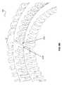
- FIG. 5Cillustrates an exemplary three-phase rotor configuration in accordance with an exemplary embodiment
- FIG. 5Dillustrates, in close-up view, exemplary magnetic and flux concentrating portions of a rotor illustrated in FIG. 5C in accordance with an exemplary embodiment
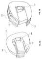
- FIG. 6Aillustrates an exemplary polyphase device having an interior stator in accordance with an exemplary embodiment
- FIG. 6Billustrates an exemplary polyphase device having an interior stator in accordance with an exemplary embodiment
- FIG. 6Cillustrates, in close-up view, a portion of the polyphase device of FIGS. 6A and 6B , wherein the inter-core flux conductor spacing has been configured to create a 90° phase lag in accordance with an exemplary embodiment
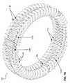
- FIG. 7Aillustrates an exemplary polyphase device having an interior rotor in accordance with an exemplary embodiment
- FIG. 7Billustrates an exemplary polyphase device having an interior rotor in accordance with an exemplary embodiment
- FIG. 7Cillustrates, in close-up view, a portion of the polyphase device of FIGS. 7A and 7B in accordance with an exemplary embodiment
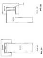
- FIG. 8Aillustrates, in a perspective view, an exemplary polyphase device having a slim design in accordance with an exemplary embodiment
- FIG. 8Billustrates, in close-up view, a portion of the polyphase device of FIG. 8A in accordance with an exemplary embodiment
- FIG. 8Cillustrates, in a face-on view, the exemplary polyphase device of FIGS. 8A and 8B in accordance with an exemplary embodiment
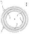
- FIG. 9Aillustrates a polyphase device of FIGS. 8A-8C having a similar polyphase device nested within in a phase-matched manner in accordance with an exemplary embodiment
- FIG. 9Billustrates a polyphase device of FIGS. 8A-8C having a similar polyphase device nested within in a phase-staggered manner in accordance with an exemplary embodiment
- FIG. 10illustrates, in cross-sectional view, an exemplary polyphase device configured for use in a vehicle in accordance with an exemplary embodiment.
- Prior electric motorsfor example conventional DC brushless motors, suffer from various deficiencies. For example, many electric motors are inefficient at various rotational speeds and/or loads, for example low rotational speeds. Thus, the motor is typically operated within a narrow RPM range and/or load range of suitable efficiency. In these configurations, gears or other mechanical approaches may be required in order to obtain useful work from the motor.
- Still other electric motorscontain large volumes of copper wire or other coil material. Due to the length of the coil windings, resistive effects in the coil lead to coil losses. For example, such losses convert a portion of electrical energy into heat, reducing efficiency and potentially leading to thermal damage to and/or functional destruction of the motor.
- torque densityrefers to Newton-meters produced per kilogram of active electrical and magnetic materials.
- many prior electric motorsare configured with a torque density from about 0.5 Newton-meters per kilogram to about 3 Newton-meters per kilogram.
- a certain electric motor with a torque density of 1 Newton-meter per kilogramproviding, for example, 10 total Newton-meters of torque may be quite heavy, for example in excess of 10 kilograms of active electrical and magnetic materials.
- another electric motor with a torque density of 2 Newton-meters per kilogramproviding, for example, 100 total Newton-meters of torque may also be quite heavy, for example in excess of 50 kilograms of active electrical and magnetic materials.
- the total weight of these electric motorsmay be significantly higher.
- such prior electric motorsare often quite bulky as a result of the large motor mass. Often, a motor of sufficient torque and/or power for a particular application is difficult or even impossible to fit in the available area.
- prior transverse flux machineshave been unable to overcome these difficulties. For example, prior transverse flux machines have suffered from significant flux leakage. Still others have offered torque densities of only a few Newton-meters per kilogram of active electrical and magnetic materials. Moreover, various prior transverse flux machines have been efficiently operable only within a comparatively narrow RPM and/or load range. Additionally, using prior transverse flux machines to generate substantial output power often required spinning relatively massive and complicated components (i.e., those involving permanent magnets and/or relatively exotic, dense and/or expensive flux concentrating or conducting materials) at high rates of speed. Such high-speed operation requires additional expensive and/or complicated components for support and/or system reliability. Moreover, many prior transverse flux machines are comparatively expensive and/or difficult to manufacture, limiting their viability.
- transverse flux machineand/or “commutated flux machine” may be any electrical machine wherein magnetic flux paths have sections where the flux is generally transverse to a rotational plane of the machine.
- the electrical machinewhen a magnet and/or flux concentrating components are on a rotor and/or are moved as the machine operates, the electrical machine may be a pure “transverse” flux machine.
- the electrical machinewhen a magnet and/or flux concentrating components are on a stator and/or are held stationary as the machine operates, the electrical machine may be a pure “commutated” flux machine.
- a “transverse flux machine”may be considered to be a “commutated flux machine” by fixing the rotor and moving the stator, and vice versa.
- a coilmay be fixed to a stator; alternatively, a coil may be fixed to a rotor.
- transverse flux machines and/or commutated flux machinesmay be configured in multiple ways.
- a commutated flux machinemay be configured with a stator 210 generally aligned with the rotational plane of a rotor 250 .
- axial gapSuch a configuration is referred to herein as “axial gap.”
- a commutated flux machinemay be configured with stator 210 rotated about 90 degrees with respect to the rotational plane of rotor 250 .
- radial gapis referred to herein as “radial gap.”
- a flux switch 352 in a commutated flux machinemay engage a stator 310 by extending at least partially into a cavity defined by stator 310 . Such a configuration is referred to herein as “cavity engaged.”
- flux switch 352 in a commutated flux machinemay engage stator 310 by closely approaching two terminal faces of stator 310 . Such a configuration is referred to herein as “face engaged.” Similar engagement approaches may be followed in transverse flux machines and are referred to in a similar manner.
- a transverse flux machine and/or commutated flux machinecomprises a rotor, a stator, and a coil.
- a flux switchmay be located on the stator or the rotor.
- a “flux switch”may be any component, mechanism, or device configured to open and/or close a magnetic circuit. (i.e., a portion where the permeability is significantly higher than air).
- a magnetmay be located on the stator or the rotor.
- a coilis at least partially enclosed by the stator or the rotor.
- flux concentrating portionsmay be included on the stator and/or the rotor.
- an exemplary transverse flux machine 100 Amay comprise a rotor 150 A, a stator 110 A, and a coil 120 A.
- a magnetmay be located on rotor 150 A.
- an exemplary commutated flux machine 100 Bmay comprise a rotor 150 B, a stator 110 B, and a coil 120 B.
- a magnetmay be located on stator 110 B.
- a transverse flux machine and/or commutated flux machinemay be configured with any suitable components, structures, and/or elements in order to provide desired electrical, magnetic, and/or physical properties.
- a commutated flux machine having a continuous, thermally stable torque density in excess of 50 Newton-meters per kilogrammay be achieved by utilizing a polyphase configuration.
- continuous, thermally stable torque densityrefers to a torque density maintainable by a motor, without active cooling, during continuous operation over a period of one hour or more.
- a continuous, thermally stable torque densitymay be considered to be a torque density maintainable by a motor for an extended duration of continuous operation, for example one hour or more, without thermal performance degradation and/or damage.
- a transverse flux machine and/or commutated flux machinemay be configured to achieve low core losses.
- core lossesmay be reduced.
- silicon steel, powdered metals, plated powdered metals, soft magnetic composites, amorphous metals, nanocrystalline composites, and/or the likemay be utilized in rotors, stators, switches, and/or other flux conducting components of a transverse flux machine and/or commutated flux machine. Eddy currents, flux leakage, and other undesirable properties may thus be reduced.
- a transverse flux machine and/or commutated flux machinemay also be configured to achieve low core losses by varying the level of saturation in a flux conductor, such as in an alternating manner.
- a flux conducting element in a statormay be configured such that a first portion of the flux conducting element saturates at a first time during operation of the stator. Similarly, a second portion of the same flux conducting element saturates at a second time during operation of the stator.
- portions of the flux conducting elementhave a level of magnetic flux density significantly below the saturation induction from time to time, reducing core loss.
- significant portions of the flux conducting elementmay have a level of flux density less than 25% of the saturation induction within the 50% of the time of its magnetic cycle.
- any suitable flux density variationsmay be utilized.
- a transverse flux machine and/or commutated flux machinemay be configured to achieve low coil losses.
- a particular transverse flux machine and/or commutated flux machinemay utilize only a small amount of copper C (for example, one-tenth as much copper C) while achieving the same output power P.
- a transverse flux machine and/or commutated flux machinemay be configured to utilize coil material in an improved manner (for example, by reducing and/or eliminating “end turns” in the coil). In this manner, resistive losses, eddy current losses, thermal losses, and/or other coil losses associated with a given coil mass C may be reduced.
- a coilmay be configured, shaped, oriented, aligned, manufactured, and/or otherwise configured to further reduce losses for a given coil mass C.
- a transverse flux machine and/or commutated flux machinemay be configured to achieve a higher voltage constant. In this manner, the number of turns in the machine may be reduced, in connection with a higher frequency. A corresponding reduction in coil mass and/or the number of turns in the coil may thus be achieved.
- a transverse flux machine and/or commutated flux machinemay be configured to achieve a high flux switching frequency, for example a flux switching frequency in excess of 1000 Hz. Because flux is switched at a high frequency, torque density may be increased.
- a typical conventional electric motor efficiency curve 402 for a particular torqueis illustrated. Revolutions per minute (RPM) is illustrated on the X axis, and motor efficiency is illustrated on the Y axis.
- RPMRevolutions per minute
- a conventional electric motortypically operates at a comparatively low efficiency at low RPM. For this conventional motor, efficiency increases and then peaks at a particular RPM, and eventually falls off as RPM increases further.
- many conventional electric motorsare often desirably operated within an RPM range near peak efficiency. For example, one particular prior art electric motor may have a maximum efficiency of about 90% at about 3000 RPM, but the efficiency falls off dramatically at RPMs that are not much higher or lower.
- Gearboxes, transmissions, and other mechanical mechanismsare often coupled to an electric motor to achieve a desired output RPM or other output condition.
- mechanical componentsare often costly, bulky, heavy, and/or impose additional energy losses, for example frictional losses.
- Such mechanical componentscan reduce the overall efficiency of the motor/transmission system.
- an electric motor operating at about 90% efficiency coupled to a gearbox operating at about 70% efficiencyresults in a motor/gearbox system having an overall efficiency of about 63%.
- a gearboxmay be larger and/or weigh more or cost more than the conventional electric motor itself. Gearboxes also reduce the overall reliability of the system.
- a transverse and/or commutated flux machine efficiency curve 404 for a particular torqueis illustrated.
- a transverse and/or commutated flux machinemay rapidly reach a desirable efficiency level (for example, 80% efficiency or higher) at an RPM lower than that of a conventional electric motor.
- the transverse and/or commutated flux machinemay maintain a desirable efficiency level across a larger RPM range than that of a conventional electric motor.
- the efficiency of the transverse and/or commutated flux machinemay fall off more slowly past peak efficiency RPM as compared to a conventional electric motor.
- a transverse and/or commutated flux machinemay achieve a torque density higher than that of a conventional electric motor.
- a transverse and/or commutated flux machinemay achieve a continuous, thermally stable torque density in excess of 100 Newton-meters per kilogram.
- a transverse and/or commutated flux machinemay desirably be employed in various applications.
- a transverse and/or commutated flux machinemay be utilized as a wheel hub motor, as a direct driveline motor, and/or the like.
- a transverse and/or commutated flux machinemay be utilized in an automotive application without need for a transmission, gearbox, and/or similar mechanical components.
- An exemplary electric or hybrid vehicle embodimentcomprises a transverse flux motor for driving a wheel of the vehicle, wherein the vehicle does not comprise a transmission, gearbox, and/or similar mechanical component(s).
- the electric or hybrid vehicleis significantly lighter than a similar vehicle that comprises a transmission-like mechanical component.
- the reduced weightmay facilitate an extended driving range as compared to a similar vehicle with a transmission like mechanical component.
- weight saved by elimination of the gearboxallows for utilization of additional batteries for extended range.
- weight saved by elimination of the gearboxallows for additional structural material for improved occupant safety.
- a commutated flux machine having a broad RPM range of suitable efficiencymay desirably be utilized in a variety of applications where a direct-drive configuration is advantageous.
- a commutated flux machine having an efficiency greater than 80% over an RPM range from only a few RPMs to about 2000 RPMsmay be desirably employed in an automobile.
- the exemplary transmissionless electric or hybrid vehiclemay have a higher overall efficiency. Stated otherwise, the exemplary vehicle may more efficiently utilize the power available in the batteries due to the improved efficiency resulting from the absence of a transmission-like component between the motor and the wheel of the vehicle. This, too, is configured to extend driving range and/or reduce the need for batteries.
- the commutated flux machineis configured to have a high torque density.
- the high torque density commutated flux machineis also well suited for use in various applications, for example automotive applications.
- a conventional electric motormay have a torque density of between about 0.5 to about 3 Newton-meters per kilogram. Additional techniques, for example active cooling, can enable a conventional electric motor to achieve a torque density of up to about 50 Newton-meters per kilogram. However, such techniques typically add significant additional system mass, complexity, bulk, and/or cost.
- such conventional electric motors configured to produce comparatively high amounts of torquefor example the Siemens 1FW6 motor, are limited to comparatively low RPM operation, for example operation below 250 RPMs.
- an exemplary passively cooled transverse flux machine and/or commutated flux machinemay be configured with a continuous, thermally stable torque density in excess of 50 Newton-meters per kilogram.
- “passively cooled”is generally understood to refer to systems without cooling components requiring power for operation, for example water pumps, oil pumps, cooling fans, and/or the like.
- this exemplary transverse flux machine and/or commutated flux machinemay be configured with a compact diameter, for example a diameter less than 14 inches.
- Another exemplary transverse flux machine and/or commutated flux machinemay be configured with a continuous, thermally stable torque density in excess of 100 Newton-meters per kilogram and a diameter less than 20 inches.
- exemplary transverse flux machines and/or commutated flux machinesmay be sized and/or otherwise configured and/or shaped in a manner suitable for mounting as a wheel hub motor in an electric vehicle, because the transverse flux machine and/or commutated flux machine is significantly lighter and/or more compact than a conventional electric motor. In this manner, the unsprung weight of the resulting wheel/motor assembly can be reduced. This can improve vehicle handling and reduce the complexity and/or size of suspension components.
- a transverse flux machine and/or commutated flux machinemay desirably be utilized in an electromechanical system having a rotating portion, for example a washing machine or other appliance.
- a conventional washing machinetypically utilizes an electric motor coupled to a belt drive to spin the washer drum.
- a transverse flux machine and/or commutated flux machinemay be axially coupled to the washer drum, providing a direct drive configuration and eliminating the belt drive element.
- a transverse flux machine and/or commutated flux machinefor example one comprising a partial stator, may be coupled to a rotor.
- the rotormay have a common axis as the washer drum.
- the rotormay also be coupled directly to the washer drum and/or integrally formed therefrom. In this manner, a transverse flux machine and/or commutated flux machine may provide rotational force for a washing machine or other similar electromechanical structures and/or systems.
- a transverse flux machine and/or commutated flux machinemay desirably be utilized to provide mechanical output to relatively lightweight vehicles such as bicycles, scooters, motorcycles, quads, golf carts, or other vehicles.
- a transverse flux machine and/or commutated flux machinemay desirably be utilized in small engine applications, for example portable generators, power tools, and other electrical equipment.
- a transverse flux machine and/or commutated flux machinemay desirably be utilized to provide mechanical output to propeller-driven devices, for example boats, airplanes, and/or the like.
- a transverse flux machine and/or commutated flux machinemay also desirably be utilized in various machine tools, for example rotating spindles, tables configured to move large masses, and/or the like.
- transverse flux machines and/or commutated flux machinesmay be utilized to provide electrical and/or mechanical input and/or output to and/or from any suitable devices.
- exemplary transverse flux and/or commutated flux machinesare configured to accommodate polyphase input and/or produce polyphase output.
- Polyphase input and/or output devicescan have various advantages compared to single-phase devices. For example, polyphase motors may not require external circuitry or other components in order to produce an initialing torque. Polyphase devices can also avoid pulsating and/or intermittency, for example pulsating and/or intermittency caused when current produced by a single phase device passes through the part of its cycle in which the current has zero amplitude. Instead, polyphase devices can deliver substantially constant power output over each period of an alternating current input, and vice versa.
- Polyphase devicescan be produced using layouts similar to single phase layouts disclosed in various co-pending applications incorporated by reference herein. Polyphase devices can also be produced using layouts having single rotor/stator sets, or layouts having polyphase features that differ from single phase rotor/stator layouts. Moreover, polyphase devices can be produced in any suitable configurations, as desired.
- exemplary embodiments shown hereingenerally have magnets on a rotor portion and flux switches on a stator portion
- flux switchesmay be mounted onto a rotor portion, and a series of magnets may be mounted onto a stator portion.
- flux switchescan be mounted onto a rotor portion and an electromagnet can be mounted onto a stator portion.
- Numerous other relationships between a stator portion and a rotor portionare also possible.
- either a stator portion or a rotor portionmay be mounted as an exterior-most component.
- magnets, flux concentrators, and/or flux switchesmay be arranged, configured, and/or coupled in order to conduct magnetic flux in such a way as to either generate electrical output or to drive the rotor.
- flux switches, flux concentrators, coils, and/or magnetscan be mounted to either of a rotor portion or a stator portion.
- a single phase device 500 Acomprises rotor 550 , a stator 510 , and a coil 520 .
- Single phase device 500 Ais illustrated here in cross section showing a transverse flux machine.
- rotor 550is cavity engaged with stator 510 in an axial gap configuration.
- Stator 510partially surrounds coil 520 .
- stator 510is held stationary and rotor 550 rotates about an axis of rotation 551 . It will be readily appreciated that in various other exemplary configurations, rotor 550 may be held stationary, so as to act as a stator. In these embodiments, stator 510 may be moved, so as to act as a rotor.
- rotor 550comprises a stack of alternating magnet and flux concentrating portions.
- polyphase device 500 Bcomprises three rotor portions 550 A, 550 B, and 500 C placed concentrically around a common axis of rotation
- polyphase device 500 Bcomprises any suitable number of rotors and/or stators, for example two rotors, four rotors, five rotors, and so on.
- rotor portions 550 A, 550 B, and 550 Ccan be capable of independent rotation.
- rotors portions 550 A, 550 B, and 550 Ccan be coupled to one another, such that rotor portions 550 A, 550 B, and 550 C rotate together.
- rotor portions 550 A, 550 B, and 550 Care very similar in design or even identical, as illustrated in FIG. 5B . In other exemplary embodiments, one or more of rotor portions 550 A, 550 B, and 550 C may be smaller than others. In yet other exemplary embodiments, rotor portions 550 A, 550 B, and 550 C differ from one another.
- a rotor portion 550(e.g., one or more of 550 A, 550 B, or 550 C) has a cross sectional shape.
- a rotor portion 550may have a wedge shape.
- the rotor portions 550may comprise various other suitable shapes, for example an arrow-head shape, a circular cross sectional shape, a rectangular cross-sectional shape, and/or the like.
- rotor portions 550 A, 550 B, and 550 Cwhen assembled into an electrically driven device and/or electrical output device, each comprise a stack of alternating magnet and flux concentrating portions.
- each rotor portion 550 A, 550 B, 550 C of polyphase device 500 Bcorresponds to a coil 520 a , 520 B, and 520 C, respectively.
- Coils 520 A, 520 B, and 520 Care typically oriented circumferentially about the center of polyphase device 500 B.
- coils 520 A, 520 B, and 520 Care fixed to the corresponding stator portion and thus do not rotate with rotor portions 550 A, 550 B, and 550 C.
- stator portions 510 A, 510 B and 510 C corresponding to each rotorare occupy at least a portion of the space between coils 520 A, 520 B, and 520 C.
- rotor portions 550 A, 550 B, and 550 Crotate independently of stator portions 510 A, 510 B and 510 C, which generally remain fixed.
- rotor portions 550 A, 550 B, 550 Ccan remain fixed so as to be the stator portion.
- coils 520 A, 520 B, and 520 C as well as stator portions 510 A, 510 B and 510 Care rotated with respect to the rotor portions.
- rotor portions 550 A, 550 B, and 550 C of FIG. 5Bare configured with a phase lag among rotor portions 510 A, 510 B and 510 C.
- Magnet portions 554 A, 554 B and 554 Care located on each of rotor portions 550 A, 550 B, and 550 C, respectively.
- multiple magnet portions 554 A, 554 B and 554 Care located on each of rotor portions 550 A, 550 B, and 550 C.
- each rotor portionmay comprise a pattern of alternating magnets and flux concentrating portions.
- rotor 550comprises a pattern of alternating magnets 554 and flux concentrating portions 552 and 556 . This pattern may be repeated about the circumference of a rotor portion 550 so as to at least partially form the shape of a rotor portion 550 .
- each of the magnet portions 554 on each of the rotors 550is located between two flux conducting portions.
- a particular magnet 554is located between flux conducting portion 552 and 556 .
- magnets 554may be arranged such that magnet surfaces having a common polarity engage a common flux concentrating portion (see, e.g., FIG. 5D ).
- a magnet portion 554may be located adjacent additional and/or fewer flux conducting portions, as desired.
- rotor portions 550 A, 550 B, and 550 Care partially rotated with respect to one another.
- a phase lag pis defined between rotor portions 550 A and 550 B.
- a phase lag p 2is defined between rotor portions 550 B and 550 C.
- additional rotors 550may be utilized to create additional phase lags, as desired.
- Rotor portions 550 A, 550 B and 550 Cmay be fixed relative to one another. In this manner, phase lags p 1 and p 2 are maintained as rotor portions 550 A, 550 B and 550 C turn while in operation. Phase lags p 1 and p 2 cause each of rotor portions 550 A, 550 B, and 550 C to produce a different phase of output. Moreover, rotor portions 550 A, 550 B, and 550 C may also be movable with respect to one another in order to vary one or more phase lags.
- phase lags p 1 and p 2 illustrated in FIG. 5Care merely representative. Numerous other phase lags and/or combinations of the same may be created in accordance with principles of the present disclosure. All such phase lags and/or resulting device input and/or output characteristics are considered to be within the scope of the present disclosure.
- polyphase device 500 Bmay be operated as an electrical output device.
- each of rotor portions 550 A, 550 B, and 550 Cgenerates an alternating electrical output (for example, a substantially sinusoidal output) in corresponding coils 520 A, 520 B, and 520 C.
- the electrical output of each coil 520 A, 520 B, and 520 Chas a phase that is shifted by a phase lag relative to each of the other coils 520 A, 520 B, and 520 C (alternatively, advanced relative to each of the other coils 520 A, 520 B, and 520 C).
- the number of phase lags in polyphase device 500 Bmay be up to one less than the number of rotor portions.
- three rotor portions 550 A, 550 B, and 550 Cmay be configured to create two phase lags.
- Three rotor portions 550 A, 550 B, and 550 Cmay also be configured to create one phase lag (for example, if rotor portions 550 B and 550 C are aligned similarly with respect to rotor portion 550 A).
- Three rotor portions 550 A, 550 B, and 550 Cmay also be configured to create no phase lag when all three rotor portions 550 A, 550 B, and 550 C are aligned similarly to one another.
- any suitable number of phase lags, and any suitable magnitude of phase lagsmay each be utilized, as desired.
- each phase lagmay be adjusted by adjusting the relative rotational alignment of each of the rotor portions 550 .
- Polyphase device 500 Bmay be operated as an electrical output device.
- phase outputsmay be shifted evenly relative to each other within each period of the alternating output.
- the phasescan be shifted relative to each other by one-third of the period.
- the phasescan be shifted unevenly with respect to one another.
- a second phasemay be shifted 30 degrees with respect to a first phase.
- a third phasemay be shifted by 60 degrees with respect to the second phase (and consequently, shifted by 90 degrees with respect to the first phase). Additional phases may similarly be shifted by any suitable value, as desired.
- each phase outputis produced by a different rotor portion 550 A, 550 B, and 550 C and corresponding stator 510 A, 510 B, and 510 C and coil 520 A, 520 B, and 520 C.
- polyphase device 500 Bis configured with a single stator portion 510 divided into separate phases sharing one or more rotors.
- the number of components of the polyphase devicemay be reduced.
- the polyphase devicemay produce and/or utilize more input/output phases than the number of rotors comprising the polyphase device.
- the size the polyphase devicemay be reduced, for example by reducing a thickness of the polyphase device in at least a direction parallel to the axis of rotation of a rotor.
- a polyphase device 600may be configured, with one or more interior stators.
- an “interior stator”refers to a stator having a portion thereof and/or various components thereof disposed substantially between two or more rotors.
- polyphase device 600comprises three stators each comprising a plurality of flux conducting portions 612 (shown as 612 A, 612 B, and 612 C).
- Polyphase device 600further comprises three coils 620 A, 620 B, 620 C, and two rotors 650 X, 650 Y.
- Flux conducting portions 612 A, 612 B, and 612 C, and coils 620 A, 620 B, and 620 Care located substantially between rotors 650 X and 650 Y.
- Coils 620 A, 620 B, and 620 Cmay each correspond to a different output phase.
- spacing between flux conducting portions 612 within stators 610is configured to create one or more phase relationships, as discussed below.
- polyphase device 600may comprise any suitable number of coils 620 , for example two coils 620 , four coils 620 , ten coils 620 , and/or the like. Accordingly, polyphase device 600 may be configured with a number of output phases up to the number of coils 620 and corresponding phase portions of one or more stators and/or rotors. Additionally, multiple coils 620 may be configured to correspond to a similar phase.
- Coils 620 A, 620 B, and 620 Ccan comprise any suitable material configured to conduct electrical current responsive to a changing magnetic field, for example copper wire windings.
- one or more coils 620are wound from flat wire (i.e., wire having a rectangular cross section, as opposed to a circular cross section).
- any of the coils, output windings, electrical connectors, and/or the like contemplated by this disclosure and/or in related disclosures, as suitablecan be fabricated from flat wire.
- Flat wire in a coil 620allows more efficient filling of available space with conductive material. In this manner, a higher packing density of wire in the coil may be achieved. Efficiency gains from the increased packing density can outweigh potential disadvantages, for example the resulting increased weight of a particular coil.
- any suitable material and/or shape of wire and/or coilmay be used.
- each of the coils 620 A, 620 B, and 620 C of polyphase device 600comprises a loop with a forward portion, 620 AF, 620 BF, 620 CF, and a rear portion, 620 AR, 620 BR, 620 CR, respectively.
- Each of the forward and rear portions of coils 620 A, 620 B, and 620 C of the polyphase device 600is substantially surrounded by flux conducting portions 612 of corresponding stators such that magnetic flux can be conducted around coils 620 A, 620 B, and 620 C.
- coils 620 A, 620 B, and 620 Cextend along a portion of a circumference of a circle.
- Coils 620 A, 620 B, and 620 Cmay extend any suitable portion of a circumference of a circle, for example approximately one-third of the circumference.
- Coils 620 A, 620 B, and 620 Cmay extend along portions having similar length.
- coils 620 A, 620 B, and 620 Cmay extend along portions having dissimilar lengths, as desired.
- forward portion 620 AFmay define a first arc, for example a semicircular arc
- rear portion 620 ARmay define a second arc, for example a semicircular arc.
- the first and second arcsmay have a common radius from a common axis, for example a rotational axis of a transverse flux and/or commutated flux machine.
- the first and second arcs (and/or forward portion 620 AF and rear portion 620 AR)may traverse a similar angular portion of a transverse flux machine. For example, in an exemplary three-phase embodiment, approximately 0° to 120° of the transverse flux machine is associated with a first coil (i.e.
- first and second arcs, (and/or forward portion 620 AF and rear portion 620 AR)may traverse overlapping angular portions of a transverse flux machine.
- forward portion 620 AFmay traverse approximately 0° to 120° of the transverse flux machine
- rear portionmay traverse approximately 5° to 115° of the transverse flux machine; thus, the angular portions are entirely overlapping.
- first and second arcsmay traverse partially overlapping angular portions of a transverse flux machine.
- forward portion 620 AFmay traverse approximately 0° to 120° of the transverse flux machine
- rear portion 620 ARmay traverse approximately 5° to 125° of the transverse flux machine; thus, the angular portions are partially overlapping.
- Conduction of flux through the flux conducting portions 612 about each of coils 620 A, 620 B, and 620 Cis able to produce an electrical output in each of coils 620 A, 620 B, and 620 C.
- fluxis conducted through flux conducting portions 612 A such that flux conducting portions 612 A substantially surrounding forward portion 620 AF are in phase with flux conducting portions 612 A substantially surrounding rear portion 620 AF.
- forward portion 620 AF and rear portion 620 ARare in phase.
- Similar phase arrangementsmay be found in portions 620 BF and 620 CF, and 620 BR and 620 CR, respectively.
- a forward portionmay be out of phase with a corresponding rear portion.
- a coilfor example coil 620 A, may be oriented about a rotational axis of polyphase device 600 such that current in forward portion 620 AF flows in a direction of rotation simultaneously with current in rear portion 620 AR flowing opposite the direction of rotation.
- current within coil 620 Amay be considered to flow around a somewhat “racetrack”-shaped loop extending only a portion of the angular distance around the rotational axis.
- coils 620 B and/or 620 Cmay be shaped, sized, aligned, configured and/or may otherwise function and/or behave in a manner similar to coil 620 A and portions thereof as described above.
- the flux conducting portions of polyphase device 600can be C-shaped.
- the flux conducting portionscan have one of a number of other shapes, for example U-shapes, rectilinear shapes, ovular shapes and linear shapes, in either cross-section or perspective, as desired.
- These flux conducting portionsmay be formed in any suitable manner.
- the flux conducting portionscan be fashioned from tape-wound torroid material, material including metallic glasses, laminated steel, powdered metal, or combinations of a number of these or other suitable flux conducting materials.
- the intra-coil flux conductor spacings S 610 A, S 610 B, and S 610 C(S 610 B and S 610 C not shown) (i.e., the spacings between adjacent flux conducting portions 612 A, 612 B, and 612 C, respectively) are approximately uniform size.
- the spacing between adjacent flux conducting portions with respect to the forward portions 620 AF, 620 BF, and 620 CF and rear portions 620 AR, 620 BR, and 620 CR, of each of the coilsare generally about the same size.
- the intra-coil flux conductor spacings S 610 A, S 610 B, and S 610 C on either and/or both the forward portions 620 AF, 620 BF, and 620 CF and rear portions 620 AR, 620 BR, and 620 CR of each of the coilscan be other than approximately equal.
- these flux conductor spacingsmay be varied in order to create different frequency outputs, or for other suitable purposes.
- the inter-coil flux conductor spacings SA-B, SB-C, and SC-A(SC-A not shown) (i.e., the on-center spacings between adjacent flux conducting portions on adjacent coils 620 A, 620 B, and 620 C), however, are generally unequal in size.
- the inter-coil flux conductor spacingsvary in order to set a particular phase relationship among the phases of the electrical output generated in each of coils 620 A, 620 B, and 620 C. These phase relationships among coils and their association with various components of the rotors will be discussed in more detail below. However, in certain cases, it may be advantageous to have one or more of the inter-core flux conductor spacings SA-B, SB-C, and SC-A be approximately equal to another.
- FIG. 6Ca close-up view of a polyphase device 600 is illustrated.
- the two rotor portions 650 X, 650 Y in polyphase device 600are at least partially received within flux conducting portions 612 comprising stators 610 .
- Rotor portions 650 X, 650 Ymay be very similar and/or identical. Additionally, rotor portions 650 X, 650 Y may have a similar construction to rotors used in single phase devices. In various exemplary embodiments, rotor portions 650 X, 650 Y are generally aligned with one another.
- rotor portions 650 X, 650 Ycan have substantial differences.
- rotor portions 650 X, 650 Ymay be at least partially rotated relative to one another. Stated another way, rotor portions 650 X, 650 Y may be unaligned.
- Rotor portions 650 X, 650 Ymay also have different sized alternating magnet portions 654 and/or flux concentrators 652 .
- alternating magnet portions 654 and flux concentrators 652are similar in features and functions to the corresponding regions 554 and 552 / 556 , respectively, of rotor 550 as illustrated in FIG. 5D .
- rotor portions 650 X, 650 Ymay be substantially similar to the rotors 550 used in polyphase device 500 B.
- adjacent magnet portions 654 of rotor portion 650 Xmay generally have alternating polar orientations.
- adjacent magnet portions 654 of rotor portion 650 Ymay generally have alternating polar orientations.
- alternate versions of rotor portion 650 Xmay be utilized, for example wherein the poles of adjacent magnet portions 654 within rotor 650 X are aligned rather than alternating. Similar alternate versions of rotor portion 650 Y may be utilized.
- all such combinations of alternating and/or aligned magnetsare considered to be within the scope of the present disclosure.
- polyphase device 600may be operated to generate electrical output from mechanical input.
- polyphase device 600may be operated in a substantially reverse manner, wherein electrical input is supplied to one or more coils in order to create mechanical output and/or other output (for example, turning of one or more rotors and/or mechanical components attached thereto). It will be appreciated by one of ordinary skill in the art that various principles may be applied to either and/or both of these configurations, as suitable.
- rotor portions 650 X, 650 Yspin relative to flux conducting portions 612 A along the direction D 1 shown in FIG. 6B .
- Thiscauses magnet portions 654 and flux concentrators 652 of rotor portions 650 X, 650 Y to alternately align with flux conducting portions 612 A. In this manner, flux is conducted along the flux conducting portions 612 A.
- orientation of successive magnet poles of each of magnet portions 654is such that each flux conducting portion 652 is at least partially surrounded by the same polarity of an abutting pair of magnet portions 654 .
- This orientationcreates a flux path from a first flux concentrator 652 , through a flux conductor 612 A, to a second flux concentrator 652 different from the first flux concentrator 652 .
- these flux pathsencircle sections of coils 620 A surrounded by flux conducting portions 612 A.
- Rotating rotor portions 650 X, 650 Ysuccessively moves flux concentrators 652 having opposing polarities near the flux conducting portions 612 A.
- rotating rotor portions 650 X, 650 Ysubstantially reverses the direction of the flux path with each sequential passing of flux concentrators 652 and flux conducting portions 612 A relative to one another. This process creates alternating electrical output in coils 620 A. Similar behavior and results may be simultaneously obtained in each of flux conducting portions 612 B and 612 C, and coils 620 B and 620 C.
- inter-coil flux conductor spacings SA-B, SB-C, and SC-Aare different than intra-coil flux conductor spacings S 610 A, S 610 B, and S 610 C.
- magnet portions 654 and flux concentrators 652 of rotors 650 X, 650 Yare aligned with flux conducting portions 612 of different stator sections 610 at different times.
- maximum flux conductance along a flux conducting portion 612 Aoccurs at a different time than for a flux conducting portion 612 B, and so on.
- the timingis governed by inter-coil flux conductor spacings SA-B, SB-C, and SC-A.
- inter-core flux conductor spacings SA-B, SB-C, and SC-Amay create a phase lag in the electrical output generated in a particular coil 620 , for example coil 620 A, with respect to the electrical output generated in one or more of the other coils 620 , for example coil 620 B.
- inter-core flux conductor spacing SA-Bis configured to create a 90° phase lag between the outputs of coils 620 A and 620 B.
- the inter-core flux conductor spacing SA-Bis such that flux conducting portions 612 A surrounding coil 620 A are aligned with the flux concentrators 654 of rotor portions 650 X, 650 Y.
- flux conducting portions 612 B surrounding coil 620 Bare aligned with magnet portions 654 of rotor portions 650 X, 650 Y. In this position, coils 620 A and 620 B are about 90° out of phase with one another.
- FIG. 6Cillustrates an inter-coil flux conductor spacing creating a 90° phase lag between adjacent coils.
- any suitable phase relationship between adjacent coilsmay be obtained by adjusting the inter-coil flux conductor spacing.
- a 180° phase lag between the output of adjacent coils 620 A and 620 Bcan be created.
- Thiscan be achieved by adjusting inter-coil flux conductor spacing SA-B. Adjusting SA-B can cause flux conducting portions 612 A surrounding coil 620 A to align with flux concentrators 652 having a first polarity at a given time T.
- Adjusting SA-Bcan also cause flux conducting portions 612 B surrounding a coil 620 B to align, at about the same time T, with flux concentrators 652 having an opposite polarity.
- Such an orientationresult in, at any given time, flux being conducted around adjacent coils 620 A and 620 B in opposing directions (e.g., flux is conducted in a generally clockwise direction around coil 620 A, while at the same time flux is conducted in a generally counter-clockwise direction around coil 620 B).
- adjusting SA-Bcan cause flux conducting portions 612 A surrounding coil 620 A to align with flux concentrators 652 having a first polarity at a given time T. Adjusting SA-B can also cause flux conducting portions 612 B surrounding a coil 620 B to align, at about the same time T, with flux concentrators 652 having the same polarity.
- coils 620 A and 620 Bare substantially in phase.
- any suitable phase relationship between coils 620for example coils 620 A and 620 B, may be achieved by configuring an inter-coil flux conductor spacing, for example SA-B.
- phase relationships between coils 620 A, 620 B, and 620 Ccan be adjusted, varied, and/or otherwise modified and/or controlled by similarly adjusting one or more of inter-coil flux conductor spacings SA-B, SB-C, and/or SC-A as discussed above. Further, these inter-coil flux conductor spacings can be adjusted independently of one another. In this manner, any suitable number of phase relationships between coils 620 A, 620 B, and/or 620 C of polyphase device 600 may be created.
- FIGS. 6A-6Cillustrate a polyphase device 600 wherein phase relationships are fixed once the stator is constructed
- polyphase devicesmay be configured with adjustable phase relationships between adjacent coils.
- flux conducting portions 612 Amay be moveable with respect to flux conducting portions 612 B. All such polyphase devices having adjustable phase relationships are considered to be within the scope of the present disclosure.
- flux conducting portions 612 associated with a particular coil 620may be interleaved and/or otherwise placed and/or arranged in an alternating manner.
- one flux conducting portion 612 Apartially encloses forward portion 620 AF.
- the next flux conducting portion 612 Apartially encloses rear portion 620 AR.
- the next flux conducting portion 612 Apartially encloses forward portion 620 AF, and so on in an alternating fashion. In this manner, flux conducting portions 612 A may be placed more compactly and/or tightly.
- flux conducting portions 612 Amay be arranged in an interleaved “back to back” configuration. In these arrangements, the “backs” of flux conducting portions 612 A may extend at least partially past one another, for example as illustrated in FIG. 6C . In this manner, polyphase device 600 may be made more compact than if flux conducting portions 612 A did not extend at least partially past one another. However, flux conducting portions 612 A may also be arranged in an alternating “back to back” configuration where portions of adjacent flux conducting portions 612 A do not extend past one another.
- flux conducting portions 612 B, 612 C, and/or other flux conducting portions of polyphase device 600may be interleaved, interspersed, and/or otherwise alternated in a similar manner.
- an “interior rotor”refers to a rotor having a portion thereof and/or various components thereof disposed substantially between two or more stators.
- a polyphase device 700is configured with an interior rotor 750 .
- Polyphase device 700further comprises three stators each comprising a plurality of flux conducting portions 712 (shown as 712 A, 712 B, and 712 C).
- Polyphase device 700further comprises three coils 720 A, 720 B, and 720 C, located substantially within and/or surrounded by flux conducting portions 712 A, 712 B, and 712 C, respectively.
- Rotor 750is also located substantially within and/or surrounded by flux conducting portions 712 A, 712 B, and 712 C.
- the arrangement of flux conducting portions 712 A, 712 B, and 712 C within polyphase device 700is substantially the inverse of the arrangement of flux conducting portions 612 A, 612 B, and 612 C within polyphase device 600 (see, e.g., FIGS. 6A-6C ), in the sense that orientation of each of flux conducting portions 712 A, 712 B, and 712 C is reversed when compared to the orientation of flux conducting portions 612 A, 612 B, and 612 C.
- polyphase device 700is configured to operate with a single rotor 750 .
- Polyphase device 700may comprise multiple coils 720 , for example coils 720 A, 720 B, and 720 C.
- Coils 720 A, 720 B, and 720 Cmay correspond to one or more output phases.
- each coil 720 A, 720 B, and 720 Ccorresponds to a different output phase.
- Any suitable number of coils 720may be utilized.
- three coils 720 A, 720 B, and 720 Cmay be utilized, corresponding to three phase portions of polyphase device 700 .
- two, four or more coils 720may be used and, correspondingly, two, four or more stators.
- the number of phases within polyphase device 700may range between one phase to a number of phases equal to the number of coils 720 present in polyphase device 700 .
- the spacing among flux conducting portions 712 A, 712 B, and 712 C associated with coils 720 A, 720 B, and 720 C, respectively,may be altered to create one or more phase relationships between them.
- functional relationships between various components of polyphase device 700are substantially similar to relationships found in polyphase device 600 .
- sizes, shapes, geometries, and/or other characteristics of components of polyphase device 700may be similar to those found in polyphase device 600 .
- the intra-coil spacing and inter-coil spacing of polyphase device 700may similarly be varied to achieve multiple phases and/or phase relationships as disclosed hereinabove.
- each of coils 720 A, 720 B, and 720 C of polyphase device 700are configured with a “bridging” segment 722 A, 722 B, and 722 C ( 722 C not shown), respectively, at a junction between adjacent coils.
- coil 720 Afurther comprises bridging segment 722 A.
- coil 720 Bfurther comprises bridging segment 722 B
- coil 720 Cfurther comprises bridging segment 722 C.
- Bridging segments 722 A and 722 Bare located at junction J 1 between coils 720 A and 720 B.
- Bridging sectionsmay be utilized in order to complete loops in coils, for example without occupying space desired for mechanical operation of rotor 750 . Bridging sections may be placed over and/or under a rotor, as desired. In this manner, a rotor may be rotated without contacting a bridging segment.
- a bridging segmentmay be placed through magnets and/or flux concentrators, as desired.
- a coilmay be coupled to a group of magnets and flux concentrators, and bridging segments may pass therethrough. Flux switches at least partially enclosing the coil may then be rotated to generate output in the coil.
- polyphase device 700may be operated in a manner at least partially similar to polyphase device 600 .
- polyphase device 700may be operated to generated electrical output by providing a mechanical input to rotor 750 .
- Polyphase device 700may also be operated to generate mechanical output at rotor 750 responsive to electrical input in one or more coils 720 .
- polyphase device 700may be configured with fixed phase relationships, for example by fixing flux conducting portions 712 A, 712 B, and 712 C with respect to one another.
- polyphase device 700may be configured with variable phase relationships, for example by allowing flux conducting portions 712 A, 712 B, and 712 C to move relative to one another, as disclosed hereinabove.
- slimrefer generally to configurations that reduce a dimension of a polyphase device, for example configurations wherein coil paths are substantially orthagonal to the axis A of the polyphase device, configurations wherein multiple rotors share a common rotational plane, and/or the like.
- a polyphase device 800is configured with a slim design.
- Polyphase device 800comprises three stators each comprising a plurality of flux conducting portions 812 (shown as 812 A, 812 B, and 812 C).
- Polyphase device 800further comprises three coils 820 A, 820 B, and 820 C.
- the paths defined by coils 820 A, 820 B, and 820 Care generally orthagonal with the axis A of rotation of polyphase device 800 (shown coming out of the page as viewed in FIG. 8A ).
- Polyphase device 800further comprises one or more rotor portions 850 (not shown).
- coils 820 A, 820 B, and 820 Ccorrespond to three phases based on intra-coil flux conductor spacing and inter-coil flux conductor spacing as previously discussed. In other exemplary embodiments, coils 820 A, 820 B, and 820 C correspond to two phases and/or one phase. Moreover, because the plane defined by coils 820 A, 820 B, 820 C is substantially orthagonal to the axis A of polyphase device 800 , polyphase device 800 may accordingly be formed to have a reduced or “slimmer” length along axis A.
- polyphase device 800may be formed to have a slimmer length along axis A than another design wherein a coil path is not orthogonal to axis A, but is rather substantially parallel to and/or at least partially traverses a distance parallel to axis A. Moreover, polyphase device 800 may slimmer than other designs having multiple rotors located at different points along axis A. Stated another way, in an exemplary embodiment, a first portion of a coil is in the same rotational plane as a second portion of that coil. In general, polyphase device 800 may be sized, shaped, and/or otherwise configured for use in various applications where a particular length along a rotational axis is desirable.
- each of the coils 820 A, 820 B, and 820 C of polyphase device 800comprises a loop with an inner portion, 820 AI, 820 BI, 820 CI, and a outer portion, 820 AO, 820 BO, 820 CO, respectively.
- outer portion 820 AOmay define a first arc, for example a first semicircular arc.
- Inner portion 820 AImay define a second arc, for example a second semicircular arc.
- the first and second arcsare concentric about a common axis, for example a rotational axis of a transverse flux machine and/or commutated flux machine.
- the first and second arcsmay also be co-planar.
- outer portions 820 AO, 820 BO, and 820 COextend along a portion of a circumference of a circle.
- Outer portions 820 AO, 820 BO, and 820 COmay extend any suitable portion of a circumference of a circle, for example approximately one-third of the circumference.
- Outer portions 820 AO, 820 BO, and 820 COmay extend along portions having similar length.
- outer portions 820 AO, 820 BO, and 820 COmay extend along portions having dissimilar lengths, as desired.
- Inner portions 820 AI, 820 BI, and 820 CImay traverse angular distances approximately corresponding to angular distances traversed by outer portions 820 AO, 820 BO, and 820 CO, respectively, for example identical angular distances.
- inner portions 820 AI, 820 BI, and 820 CImay traverse different angular distances.
- functional relationships between various components of polyphase device 800are substantially similar to relationships found in polyphase device 600 .
- sizes, shapes, geometries, and/or other characteristics of components of polyphase device 800may be similar to those found in polyphase device 600 .
- an intra-coil flux conductor spacing and/or inter-coil flux conductor spacing of polyphase device 800may similarly be varied to achieve multiple phases and/or phase relationships as disclosed hereinabove.
- polyphase device 800may be operated in a manner at least partially similar to polyphase device 600 .
- polyphase device 800may be operated to generated electrical output by providing a mechanical input to a rotor.
- Polyphase device 800may also be operated to generate mechanical output at a rotor responsive to electrical input in one or more coils 820 .
- polyphase device 800may be configured with fixed phase relationships, for example by fixing flux conducting portions 812 A, 812 B, and 812 C with respect to one another.
- polyphase device 800may be configured with variable phase relationships, for example by allowing flux conducting portions 812 A, 812 B, and 812 C to move relative to one another, as disclosed hereinabove.
- polyphase device 800may be configured to reduce the amount of coil material at a junction between adjacent coils.
- one or more bridging sections 822 A, 822 B, and 822 C 822 Bcomplete coils 820 A, 820 B, and 820 C, respectively.
- bridging sections 822 A and 822 Bcomplete coils 820 A and 820 B at junction J 2 .
- Bridging sections 822 A, 822 B, and 822 Cmay be significantly thinner than corresponding bridging sections 722 A, 722 B, and 722 C for polyphase device 700 .
- bridging sections 822 A, 822 B, and 822 Care thinner in a “slim” configuration because bridging sections 822 A, 822 B, and 822 C may not need to extend out of the plane of the main body of coils 820 A, 820 B, and 820 C, respectively, for example in order to allow clearance for a rotor. In this manner, the amount of material utilized in coils 820 A, 820 B, and 820 C may be desirably reduced.
- coil material comprising bridging sections 822 A, 822 B, and 822 Cis not at least partially surrounded by a corresponding flux conducting portion 812 A, 812 B, or 812 C, this material is generally not generating useful output, but rather losses.
- this materialmay be considered to be somewhat similar to material in an “end turn” in a conventional motor, and as such may be suitably reduced and/or minimized, as desired.
- polyphase device 800may accommodate a suitable number of rotors, for example two rotors, in order to allow interaction between the rotors and various portions of polyphase device 800 .
- polyphase device 800may comprise any suitable number of rotors, as desired.
- a first polyphase deviceis “nested” within another polyphase device, for example about a common axis.
- a “nested” configurationrefers to a single-phase and/or polyphase device surrounding another single-phase and/or polyphase device having a common axis.
- the resulting combined polyphase devicemay be configured with an increased mechanical and/or electrical output potential for a particular device size.
- multiple nested polyphase devicesmay be connected to the same mechanical device, such as the drive shaft for a vehicle.
- a combined polyphase devicecan provide many times, for example three times, the output of an un-nested polyphase device, with essentially the same footprint.
- These configurationscan be particularly advantageous for applications requiring a higher power output in a relatively compact and/or fixed space, for example motors for electric vehicles or other electric motors.
- Nested polyphase devicescan also be used, for example, to derive a greater amount of electrical output from a similar amount of mechanical input. Such an approach enables more compact electrical generator designs, turbine designs, and/or designs for devices incorporating the same.
- a nested polyphase device 900comprises a first polyphase device 900 A and a second polyphase device 900 B.
- Second polyphase device 900 Bmay be substantially similar to first polyphase device 900 A.
- second polyphase device 900 Bmay be a scaled-down or smaller version of first polyphase device 900 A.
- second polyphase device 900 Bmay be configured with a design substantially different from first polyphase device 900 A.
- Second polyphase device 900 Bis configured to be located at least partially within first polyphase device 900 A.
- phase relationships between first polyphase device 900 A and second polyphase device 900 Bmay be maintained, varied, and/or controlled by utilizing similarly sized components therein, but utilizing different stator component spacing, different rotor configurations, and/or the like.
- certain components of second polyphase device 900 B and/or other components and/or features of polyphase device 900are scaled down in size from similar components in first polyphase device 900 A, for example by an approximately consistent scaling factor.
- flux conducting portions 912 B of second polyphase device 900 Bare approximately half the size of flux conducting portions 912 A of first polyphase device 900 A.
- a spacing between adjacent flux conducting portions 912 B on second polyphase device 900 Bmay be approximately half that of a spacing between adjacent flux conducting portions 912 A on first polyphase device 900 A.
- a rotor utilized in second polyphase device 900 Bmay be a scaled down version of a rotor utilized in first polyphase device 900 A, for example a rotor scaled down by a similar factor.
- magnet portions and flux concentrating portions of a rotor for second polyphase device 900 Bmay be approximately half the size of magnet portions and flux concentrating portions of a rotor for first polyphase device 900 A.
- a rotor for second polyphase device 900 Bis connected to the same mechanical input/output device as a rotor for first polyphase device 900 A so as to operate in tandem.
- This arrangementcan be advantageous, for example in applications with spatial restrictions.
- these rotorsmay also be coupled to different mechanical devices, such that first polyphase device 900 A and second polyphase device 900 B may be utilized substantially independently.
- polyphase device 900may comprise any suitable number of nested polyphase devices.
- an area comprising an interior section of a particular polyphase devicemay be substantially filled with one or more additional polyphase and/or single-phase devices in order to form polyphase device 900 .
- a physical alignmentmay exist between like phase portions of a first polyphase device 900 A and a second polyphase device 900 B (see, e.g., FIG. 9A ).
- a coil 920 A of first polyphase device 900 A and a corresponding coil 920 B of second polyphase device 900 Bare configured to correspond to approximately a same input/output phase.
- corresponding coilse.g., 920 A and 920 B
- corresponding coilsmay be electrically connected so as to provide similar output or to receive a similar input.
- corresponding coilsmay be connected in other arrangements more suited for a particular implementation.
- polyphase device 900may comprise a phase-staggered configuration.
- polyphase device 900comprises a first polyphase device 900 A and a second, similar polyphase device 900 B nested therein in a phase-staggered configuration.
- similar phase portions of first polyphase device 900 A and second polyphase device 900 Bfor example coils 920 A and 920 B, are staggered in order to increase a distance therebetween. In this manner, electrical interference between similar phase portions may be reduced.
- phase staggeringmay reduce noise, vibration, and/or the like, for example by a mechanical pulse generated in one portion of the device corresponding to a similar mechanical pulse generated at approximately the same time on an opposite side.
- portions of first polyphase device 900 A corresponding to approximately the same input/output phase as portions of second polyphase device 900 Bmay be located on generally opposite sides of polyphase device 900 .
- coils 920 A and 920 Bcorrespond to approximately the same output phase.
- Coils 920 A and 920 Bmay be located approximately 180 rotational degrees away from one another about an axis of rotation of polyphase device 900 .
- coils 920 A and 920 Bmay be located on generally opposite sides of polyphase device 900 . In this manner, physical separation between corresponding phases may be maximized.
- FIGS. 5A-5Cillustrate axial gap configurations. Certain exemplary embodiments, including but not limited to those depicted therein, may alternatively be configured with radial gap configurations, as desired.
- FIGS. 6A-6C , 7 A- 7 C, 8 A- 8 C, 9 A- 9 B, and 10illustrate radial gap configurations.
- FIGS. 5A-5B , 6 A- 6 C, 7 A- 7 C, 8 A- 8 C, 9 A- 9 B, and 10illustrate cavity engaged configurations.
- Various exemplary embodiments, including but not limited to those depicted therein,may alternatively be configured with face engaged configurations, as desired.
- FIG. 5Cillustrates a face engaged configuration.
- Various other exemplary embodiments, including but not limited to those depicted therein,may also be configured with cavity engaged configurations, as desired.
- FIGS. 5A-10illustrate transverse flux machine configurations.
- Various exemplary embodiments, including but not limited to those depicted therein,may alternatively be configured with commutated flux machine configurations.
- a polyphase devicemay utilize a plurality of partial stators sharing a common rotor, for example a multipath rotor.
- a polyphase devicemay comprise three partial stators sharing a common rotor, each partial stator corresponding to an input and/or output phase.
- a polyphase devicemay comprise any suitable number of partial stators, as desired. Use of one or more partial stators may facilitate assembly and/or disassembly of a polyphase device.
- partial statorsmay also facilitate scalable and/or modular polyphase devices, wherein partial stators may be added and/or removed, as desired.
- a partial statormay be added and/or removed in order to modify one or more properties of a polyphase device, for example a torque density, a power output, an input and/or output electrical waveform, and/or the like.
- a polyphase devicemay be configured for use in a vehicle.
- a polyphase device 1000may be mounted on an axle of a wheel. In this manner, polyphase device 1000 may function as a direct drive hub motor.
- polyphase device 1000may be similar to polyphase device 700 having an interior rotor.
- polyphase device 1000comprises at least two coils 1020 A and 1020 B, and a rotor 1050 disposed between portions of each of coils 1020 A and 1020 B.
- any suitable polyphase devicemay be utilized in a vehicle, and the exemplary embodiments presented herein are by way of illustration and not of limitation.
- Principles of the present disclosuremay suitably be combined with principles for stators in transverse flux machines and commutated flux machines, for example principles for partial stators and/or gapped stators, as disclosed in a co-pending U.S. Patent Application entitled “TRANSVERSE AND/OR COMMUTATED FLUX SYSTEM STATOR CONCEPTS” having the same filing date as the present application, the contents of which are hereby incorporated by reference in their entirety.
- Principles of the present disclosuremay also suitably be combined with principles for rotors in transverse flux machines and commutated flux machines, for example tape wound rotors and/or multipath rotors, as disclosed in a co-pending U.S. Patent Application entitled “TRANSVERSE AND/OR COMMUTATED FLUX SYSTEM ROTOR CONCEPTS” having the same filing date as the present application, the contents of which are hereby incorporated by reference in their entirety.
- transverse flux machine and/or commutated flux machinemay incorporate use of a tape wound rotor, use of a multipath rotor, use of a partial stator, use of a polyphase design, and/or the like. All such combinations, permutations, and/or other interrelationships are considered to be within the scope of the present disclosure.
- the terms “comprises,” “comprising,” or any other variation thereof,are intended to cover a non-exclusive inclusion, such that a process, method, article, or apparatus that comprises a list of elements does not include only those elements but may include other elements not expressly listed or inherent to such process, method, article, or apparatus.
- the terms “coupled,” “coupling,” or any other variation thereofare intended to cover a physical connection, an electrical connection, a magnetic connection, an optical connection, a communicative connection, a functional connection, and/or any other connection.
- An electrical machinecomprising: a conductive coil comprising a first coil portion, a second coil portion, a first coil end, and a second coil end, wherein the first coil portion and the second coil portion are connected via the first coil end and the second coil end to form a loop, wherein a voltage is induced in more than 90% of the coil mass, and wherein the electrical machine is at least one of a transverse flux machine or a commutated flux machine.
- An electrical machinecomprising: a first rotor having a first plane of rotation; a second rotor having a second plane of rotation parallel to and non-overlapping the first plane of rotation, wherein the first rotor and second rotor have a common rotational axis; and a stator at least partially enclosing a coil, wherein the stator is located substantially between the first rotor and the second rotor, wherein the stator engages the first rotor and the second rotor, and wherein the electrical machine is at least one of a transverse flux machine or a commutated flux machine.
- An electrical machinecomprising: a conductive coil comprising a first coil portion, a second coil portion, a first coil end, and a second coil end, wherein the first coil portion and the second coil portion are connected via the first coil end and the second coil end to form a loop; a first set of flux conductors at least partially enclosing the first coil portion, wherein the first set of flux conductors engage a first rotor; and a second set of flux conductors at least partially enclosing the second coil portion, wherein the second set of flux conductors engage a second rotor, wherein the first set and the second set are arranged back-to-back, and wherein the electrical machine is at least one of a transverse flux machine or a commutated flux machine.
- the first set and the second setare arranged in an alternating manner.
- An electrical machinecomprising: a conductive coil comprising a first coil portion, a second coil portion, a first coil end, and a second coil end, wherein the first coil portion and the second coil portion are connected via the first coil end and the second coil end to form a loop; and a rotor, wherein the first coil portion is located on a first side of the rotor, wherein the second coil portion is located on an opposite side of the rotor, wherein the first coil end and the second coil end extend from the first side of the rotor to the opposite side of the rotor to form the loop, and wherein the electrical machine is at least one of a transverse flux machine or a commutated flux machine.
- the first coil endmay comprise a bridging segment traversing the rotor such that the rotor is between the bridging segment and an axis of rotation.
- the first coil endmay comprise a bridging segment passing between the rotor and an axis of rotation.
- the electrical machinemay be a polyphase machine.
- the electrical machinemay further comprise a first set of flux conductors at least partially enclosing the first coil portion, wherein the first set of flux conductors engage a first side of the rotor, and a second set of flux conductors at least partially enclosing the second coil portion, wherein the second set of flux conductors engage a second side of the rotor different from the first side, and wherein the first side and the second side are separated by a rotational plane of the rotor.
- An electrical machinecomprising: a rotor having a first side and a second side separated by a rotational plane of the rotor; a first set of flux conducting portions engaging the first side; a second set of flux conducting portions engaging the second side; and a coil at least partially enclosed by the first set of flux conducting portions and the second set of flux conducting portions, wherein the electrical machine is at least one of a transverse flux machine or a commutated flux machine.
- a nested electrical machinecomprising: a first electrical machine and a second electrical machine having a common rotational axis, wherein the second electrical machine is disposed entirely within an inner radius of the first electrical machine, wherein the first electrical machine is at least one of a transverse flux machine or a commutated flux machine, and wherein the second electrical machine is at least one of a transverse flux machine or a commutated flux machine.
- the first electrical machine and the second electrical machinemay differ in phase.
- An electrical machinecomprising: a rotor; and a plurality of partial stators coupled to the rotor, wherein each partial stator of the plurality of partial stators corresponds to a different input/output phase, and wherein the electrical machine is at least one of a transverse flux machine or a commutated flux machine.
- An electrical machinecomprising: a first rotor having a first radius; a second rotor having a second radius smaller than the first radius, the first rotor and the second rotor having a common rotational plane; a conductive coil comprising a first coil portion, a second coil portion, a first coil end, and a second coil end, wherein the first coil portion and the second coil portion are connected via the first coil end and the second coil end to form a loop; wherein the first coil portion is at least partially enclosed by a first set of flux conductors, wherein the second coil portion is at least partially enclosed by a second set of flux conductors, wherein the first set of flux conductors engage only the first rotor, and wherein the second set of flux conductors engage only the second rotor.
Landscapes
- Engineering & Computer Science (AREA)
- Power Engineering (AREA)
- Physics & Mathematics (AREA)
- Chemical & Material Sciences (AREA)
- Combustion & Propulsion (AREA)
- Electromagnetism (AREA)
- Iron Core Of Rotating Electric Machines (AREA)
- Windings For Motors And Generators (AREA)
- Permanent Magnet Type Synchronous Machine (AREA)
- Synchronous Machinery (AREA)
- Permanent Field Magnets Of Synchronous Machinery (AREA)
Abstract
Description
Claims (15)
Priority Applications (3)
| Application Number | Priority Date | Filing Date | Title |
|---|---|---|---|
| US12/611,737US7868508B2 (en) | 2008-11-03 | 2009-11-03 | Polyphase transverse and/or commutated flux systems |
| US12/948,925US7994678B2 (en) | 2008-11-03 | 2010-11-18 | Polyphase transverse and/or commutated flux systems |
| US13/173,513US8193679B2 (en) | 2008-11-03 | 2011-06-30 | Polyphase transverse and/or commutated flux systems |
Applications Claiming Priority (7)
| Application Number | Priority Date | Filing Date | Title |
|---|---|---|---|
| US11088908P | 2008-11-03 | 2008-11-03 | |
| US11087908P | 2008-11-03 | 2008-11-03 | |
| US11088408P | 2008-11-03 | 2008-11-03 | |
| US11087408P | 2008-11-03 | 2008-11-03 | |
| US11488108P | 2008-11-14 | 2008-11-14 | |
| US16844709P | 2009-04-10 | 2009-04-10 | |
| US12/611,737US7868508B2 (en) | 2008-11-03 | 2009-11-03 | Polyphase transverse and/or commutated flux systems |
Related Child Applications (1)
| Application Number | Title | Priority Date | Filing Date |
|---|---|---|---|
| US12/948,925DivisionUS7994678B2 (en) | 2008-11-03 | 2010-11-18 | Polyphase transverse and/or commutated flux systems |
Publications (2)
| Publication Number | Publication Date |
|---|---|
| US20100109453A1 US20100109453A1 (en) | 2010-05-06 |
| US7868508B2true US7868508B2 (en) | 2011-01-11 |
Family
ID=42130517
Family Applications (9)
| Application Number | Title | Priority Date | Filing Date |
|---|---|---|---|
| US12/611,737ActiveUS7868508B2 (en) | 2008-11-03 | 2009-11-03 | Polyphase transverse and/or commutated flux systems |
| US12/611,728ActiveUS7851965B2 (en) | 2008-11-03 | 2009-11-03 | Transverse and/or commutated flux system stator concepts |
| US12/611,733Expired - Fee RelatedUS7923886B2 (en) | 2008-11-03 | 2009-11-03 | Transverse and/or commutated flux system rotor concepts |
| US12/942,495Expired - Fee RelatedUS8008821B2 (en) | 2008-11-03 | 2010-11-09 | Transverse and/or commutated flux system stator concepts |
| US12/948,925ActiveUS7994678B2 (en) | 2008-11-03 | 2010-11-18 | Polyphase transverse and/or commutated flux systems |
| US13/039,837ActiveUS8030819B2 (en) | 2008-11-03 | 2011-03-03 | Transverse and/or commutated flux system rotor concepts |
| US13/173,513ActiveUS8193679B2 (en) | 2008-11-03 | 2011-06-30 | Polyphase transverse and/or commutated flux systems |
| US13/187,744AbandonedUS20110273035A1 (en) | 2008-11-03 | 2011-07-21 | Transverse and/or commutated flux system stator concepts |
| US13/230,522ActiveUS8242658B2 (en) | 2008-11-03 | 2011-09-12 | Transverse and/or commutated flux system rotor concepts |
Family Applications After (8)
| Application Number | Title | Priority Date | Filing Date |
|---|---|---|---|
| US12/611,728ActiveUS7851965B2 (en) | 2008-11-03 | 2009-11-03 | Transverse and/or commutated flux system stator concepts |
| US12/611,733Expired - Fee RelatedUS7923886B2 (en) | 2008-11-03 | 2009-11-03 | Transverse and/or commutated flux system rotor concepts |
| US12/942,495Expired - Fee RelatedUS8008821B2 (en) | 2008-11-03 | 2010-11-09 | Transverse and/or commutated flux system stator concepts |
| US12/948,925ActiveUS7994678B2 (en) | 2008-11-03 | 2010-11-18 | Polyphase transverse and/or commutated flux systems |
| US13/039,837ActiveUS8030819B2 (en) | 2008-11-03 | 2011-03-03 | Transverse and/or commutated flux system rotor concepts |
| US13/173,513ActiveUS8193679B2 (en) | 2008-11-03 | 2011-06-30 | Polyphase transverse and/or commutated flux systems |
| US13/187,744AbandonedUS20110273035A1 (en) | 2008-11-03 | 2011-07-21 | Transverse and/or commutated flux system stator concepts |
| US13/230,522ActiveUS8242658B2 (en) | 2008-11-03 | 2011-09-12 | Transverse and/or commutated flux system rotor concepts |
Country Status (6)
| Country | Link |
|---|---|
| US (9) | US7868508B2 (en) |
| EP (3) | EP2342802A2 (en) |
| JP (3) | JP2012507983A (en) |
| KR (3) | KR20110086063A (en) |
| CN (3) | CN102257709A (en) |
| WO (3) | WO2010062765A2 (en) |
Cited By (19)
| Publication number | Priority date | Publication date | Assignee | Title |
|---|---|---|---|---|
| US20110148225A1 (en)* | 2008-11-03 | 2011-06-23 | Motor Excellence Llc | Transverse and/or commutated flux system rotor concepts |
| US8053944B2 (en) | 2010-03-15 | 2011-11-08 | Motor Excellence, Llc | Transverse and/or commutated flux systems configured to provide reduced flux leakage, hysteresis loss reduction, and phase matching |
| US8222786B2 (en) | 2010-03-15 | 2012-07-17 | Motor Excellence Llc | Transverse and/or commutated flux systems having phase offset |
| US8395291B2 (en) | 2010-03-15 | 2013-03-12 | Electric Torque Machines, Inc. | Transverse and/or commutated flux systems for electric bicycles |
| US8405275B2 (en) | 2010-11-17 | 2013-03-26 | Electric Torque Machines, Inc. | Transverse and/or commutated flux systems having segmented stator laminations |
| US20140084712A1 (en)* | 2012-09-24 | 2014-03-27 | Eocycle Technologies Inc. | Transverse flux electrical machine stator components |
| US8836196B2 (en) | 2010-11-17 | 2014-09-16 | Electric Torque Machines, Inc. | Transverse and/or commutated flux systems having segmented stator laminations |
| US8952590B2 (en) | 2010-11-17 | 2015-02-10 | Electric Torque Machines Inc | Transverse and/or commutated flux systems having laminated and powdered metal portions |
| US9006951B2 (en) | 2011-06-28 | 2015-04-14 | Electric Torque Machines Inc | Cogging torque reduction device for electrical machines |
| US9236773B2 (en) | 2013-08-16 | 2016-01-12 | Electric Torque Machines Inc | Segmented stator with controlled eddy current |
| US9269483B2 (en) | 2011-04-13 | 2016-02-23 | Boulder Wind Power, Inc. | Flux focusing arrangement for permanent magnets, methods of fabricating such arrangements, and machines including such arrangements |
| US9331531B2 (en) | 2012-10-17 | 2016-05-03 | Eocycle Technologies Inc. | Method of manufacturing a transverse flux electrical machine rotor |
| US9509181B2 (en) | 2013-12-10 | 2016-11-29 | Electric Torque Machines Inc. | Transverse flux stator geometry |
| US9680339B2 (en) | 2013-01-04 | 2017-06-13 | Moog Inc. | Metal ribbon stator and motor comprising same |
| US9722479B2 (en) | 2012-08-03 | 2017-08-01 | Eocycle Technologies Inc. | Wind turbine comprising a transverse flux electrical machine |
| US9742226B2 (en) | 2015-08-11 | 2017-08-22 | Genesis Robotics Llp | Electric machine |
| US9899886B2 (en) | 2014-04-29 | 2018-02-20 | Boulder Wind Power, Inc. | Devices and methods for magnetic flux return optimization in electromagnetic machines |
| US11043885B2 (en) | 2016-07-15 | 2021-06-22 | Genesis Robotics And Motion Technologies Canada, Ulc | Rotary actuator |
| US11139707B2 (en) | 2015-08-11 | 2021-10-05 | Genesis Robotics And Motion Technologies Canada, Ulc | Axial gap electric machine with permanent magnets arranged between posts |
Families Citing this family (55)
| Publication number | Priority date | Publication date | Assignee | Title |
|---|---|---|---|---|
| WO2010083054A1 (en) | 2009-01-16 | 2010-07-22 | Jore Matthew B | Segmented stator for an axial field device |
| EP3751704A1 (en) | 2009-02-05 | 2020-12-16 | Evr Motors Ltd. | Electrical machine |
| US20120032084A1 (en)* | 2009-04-15 | 2012-02-09 | Koninklijke Philips Electronics N. V. | Drive with curved linear induction motor |
| SG179062A1 (en)* | 2009-09-08 | 2012-04-27 | Green Ray Technologies Llc | Arbitrary phase relationship for electrical connections in n-phase electric machines |
| BR112012012614A2 (en)* | 2009-11-25 | 2018-06-05 | Cabot Corp | airgel composites and method for making and using them. |
| US9154024B2 (en) | 2010-06-02 | 2015-10-06 | Boulder Wind Power, Inc. | Systems and methods for improved direct drive generators |
| US8749108B2 (en)* | 2011-03-15 | 2014-06-10 | Electric Torque Machines, Inc. | Transverse and/or commutated flux systems having laminated and powdered metal portions |
| JP5800352B2 (en)* | 2011-03-23 | 2015-10-28 | Necネットワーク・センサ株式会社 | Communication device and electronic device |
| TWM422528U (en)* | 2011-07-13 | 2012-02-11 | Xu Hong Jun | Transmission detection device for central axle |
| KR101259171B1 (en)* | 2011-09-26 | 2013-04-30 | 이형진 | High efficiency electric motor, high efficiency electric generator |
| US8994243B2 (en) | 2011-11-08 | 2015-03-31 | Electric Torque Machines Inc | Transverse and/or commutated flux systems having multidirectional laminations |
| US9300194B2 (en)* | 2011-11-09 | 2016-03-29 | Hamilton Sundstrand Corporation | Electromagnetic device |
| EP2604876B1 (en)* | 2011-12-12 | 2019-09-25 | Siemens Aktiengesellschaft | Magnetic radial bearing with individual core plates in tangential direction |
| CN102522834B (en)* | 2012-01-01 | 2013-12-04 | 中国船舶重工集团公司第七一二研究所 | Novel transverse flux motor |
| US10284029B2 (en) | 2012-03-20 | 2019-05-07 | Linear Labs, LLC | Brushed electric motor/generator |
| US10263480B2 (en) | 2012-03-20 | 2019-04-16 | Linear Labs, LLC | Brushless electric motor/generator |
| US9729016B1 (en) | 2012-03-20 | 2017-08-08 | Linear Labs, Inc. | Multi-tunnel electric motor/generator |
| EP2828962B1 (en) | 2012-03-20 | 2021-05-12 | Linear Labs, Inc. | An improved dc electric motor/generator with enhanced permanent magnet flux densities |
| DE102012205826B4 (en)* | 2012-04-11 | 2024-05-08 | Bayerische Motoren Werke Aktiengesellschaft | High-voltage pinion starter |
| US9461508B2 (en) | 2012-05-30 | 2016-10-04 | Prototus, Ltd. | Electromagnetic generator transformer |
| US10476324B2 (en)* | 2012-07-06 | 2019-11-12 | Persimmon Technologies Corporation | Hybrid field electric motor |
| US8339019B1 (en) | 2012-07-30 | 2012-12-25 | Boulder Wind Power, Inc. | Structure for an electromagnetic machine having compression and tension members |
| DE102012222194A1 (en)* | 2012-12-04 | 2014-06-05 | Schaeffler Technologies Gmbh & Co. Kg | Method for producing transverse flux machine, involves inserting primary sub-segments in conductor ring, and bonding mechanically primary sub-segments with one another to circular primary ring |
| US8736133B1 (en) | 2013-03-14 | 2014-05-27 | Boulder Wind Power, Inc. | Methods and apparatus for overlapping windings |
| TWI491145B (en)* | 2013-04-30 | 2015-07-01 | Ghing Hsin Dien | Electric machine |
| JP5886799B2 (en)* | 2013-08-05 | 2016-03-16 | 富士重工業株式会社 | Outside environment recognition device |
| WO2015040620A1 (en) | 2013-09-18 | 2015-03-26 | E.V.R. Motors Ltd. | Multipole electrical machine |
| US10570494B2 (en) | 2013-09-30 | 2020-02-25 | Persimmon Technologies Corporation | Structures utilizing a structured magnetic material and methods for making |
| EP3036351B1 (en) | 2013-09-30 | 2021-02-24 | Persimmon Technologies Corporation | Method of making a soft magnetic material |
| US20150147188A1 (en)* | 2013-11-25 | 2015-05-28 | Macroair Technologies, Inc. | High Volume Low Speed Fan Using Direct Drive Transverse Flux Motor |
| US10177620B2 (en) | 2014-05-05 | 2019-01-08 | Boulder Wind Power, Inc. | Methods and apparatus for segmenting a machine |
| US10122251B2 (en) | 2015-05-29 | 2018-11-06 | Com Dev Ltd. | Sequential actuator with sculpted active torque |
| US10447103B2 (en) | 2015-06-28 | 2019-10-15 | Linear Labs, LLC | Multi-tunnel electric motor/generator |
| US10476362B2 (en) | 2015-06-28 | 2019-11-12 | Linear Labs, LLC | Multi-tunnel electric motor/generator segment |
| DE102015212791A1 (en)* | 2015-07-08 | 2017-01-12 | Fgb A. Steinbach Gmbh & Co. Kg | Secondary part and primary part for a transverse flux machine |
| US10355569B2 (en)* | 2015-07-20 | 2019-07-16 | Eocycle Technologies Inc. | Core for transverse flux electrical machine |
| CN105207377A (en)* | 2015-10-13 | 2015-12-30 | 石瑛汉宫 | Novel efficient energy-saving direct current motor |
| WO2017070403A1 (en) | 2015-10-20 | 2017-04-27 | Linear Labs, Inc. | A circumferential flux electric machine with field weakening mechanisms and methods of use |
| JP2019527022A (en) | 2016-09-05 | 2019-09-19 | リニア ラブズ リミテッド ライアビリティ カンパニー | Improved multi-tunnel electric motor / generator |
| CN111566900A (en)* | 2017-11-13 | 2020-08-21 | 星转股份有限公司 | Induction motor |
| DE102018210163A1 (en)* | 2018-06-22 | 2019-12-24 | Hs Products Engineering Gmbh | Stator device, flat electric motor and method for producing a stator device |
| US11296585B2 (en) | 2018-12-21 | 2022-04-05 | The University Of Akron | Single stack multiphase transverse flux machines |
| GB2580920A (en)* | 2019-01-29 | 2020-08-05 | Saietta Group Ltd | Axial flux electrical machine and ancillary components |
| WO2020214856A1 (en) | 2019-04-17 | 2020-10-22 | Bard Access Systems, Inc. | Catheter securement device including extended anchor pad and release liner clasping features |
| DE102019206460B3 (en)* | 2019-05-06 | 2020-09-03 | Fertigungsgerätebau Adolf Steinbach GmbH & Co. KG | Rotating multiphase transverse flux machine |
| US11277062B2 (en) | 2019-08-19 | 2022-03-15 | Linear Labs, Inc. | System and method for an electric motor/generator with a multi-layer stator/rotor assembly |
| US11316390B2 (en) | 2019-09-06 | 2022-04-26 | The University Of Akron | Transverse flux machines |
| CN111064335B (en)* | 2020-01-02 | 2021-07-09 | 东南大学 | An E-type double-winding stator axial flux motor with amorphous material |
| WO2021163156A1 (en) | 2020-02-10 | 2021-08-19 | Electric Torque Machines, Inc. | Transverse flux electric machine |
| DE102020113047A1 (en)* | 2020-05-14 | 2021-11-18 | Schaeffler Technologies AG & Co. KG | Electric motor component and method for manufacturing an electric motor component of an axial flux motor |
| CN116171522A (en) | 2020-08-12 | 2023-05-26 | 电动扭矩机械公司 | electric motor |
| WO2022066616A2 (en) | 2020-09-24 | 2022-03-31 | Electric Torque Machines, Inc. | Marine propeller system with high torque drive |
| GB2613841A (en)* | 2021-12-16 | 2023-06-21 | Saietta Group PLC | Stacked-winding stator electrical machine |
| DE102022127817A1 (en) | 2022-04-25 | 2023-10-26 | Rolls-Royce Deutschland Ltd & Co Kg | Assembly for an electrical machine |
| CN117647166B (en)* | 2023-12-07 | 2024-07-09 | 宁波巨龙尺业制造有限公司 | Double-layer tape measure |
Citations (178)
| Publication number | Priority date | Publication date | Assignee | Title |
|---|---|---|---|---|
| US1361136A (en) | 1917-02-06 | 1920-12-07 | Burke Electric Company | Dynamo-electric machine |
| US2078668A (en) | 1935-11-29 | 1937-04-27 | Westinghouse Electric & Mfg Co | Low-loss dynamo-electric machine |
| GB518298A (en) | 1937-09-08 | 1940-02-22 | British Thomson Houston Co Ltd | Improvements in and relating to electric motors |
| US3403273A (en) | 1965-02-26 | 1968-09-24 | Tanaka Instr Company Ltd | Self-starting synchronous motor |
| DE1513856A1 (en) | 1966-02-04 | 1969-04-03 | Giffey Pretre S A Ets | Alternator |
| US3437854A (en) | 1965-11-08 | 1969-04-08 | Fujitsu Ltd | Electric rotary step motor with plural offset stator windings |
| US3558941A (en) | 1968-07-04 | 1971-01-26 | Giorgio Visconti Brebbia | Permanent magnet stepping motor with single winding |
| US3700942A (en) | 1971-02-03 | 1972-10-24 | Max Alth | Self-starting synchronous motors |
| US3710158A (en) | 1970-10-30 | 1973-01-09 | Bosch Gmbh Robert | Alternating current generator with radial stator poles |
| US3774059A (en) | 1971-09-13 | 1973-11-20 | Cambridge Thermionic Corp | Rotary stepping motor with laminated stator and rotor pole construction |
| US4021691A (en) | 1975-02-18 | 1977-05-03 | Alexandr Antonovich Dukshtau | Electrical machine stator |
| US4114057A (en) | 1976-12-06 | 1978-09-12 | Esters Ernie B | Dynamoelectric machine with inner and outer stators |
| US4206374A (en) | 1976-07-05 | 1980-06-03 | U.S. Philips Corporation | Synchronous motor |
| US4237396A (en) | 1977-10-06 | 1980-12-02 | P A Management Consultants Limited | Electromagnetic machines with permanent magnet excitation |
| US4363988A (en) | 1978-06-12 | 1982-12-14 | General Electric Company | Induction disk motor with metal tape components |
| GB2052176B (en) | 1979-06-20 | 1983-04-20 | Philips Nv | Stepping motor |
| US4388545A (en) | 1981-06-10 | 1983-06-14 | General Electric Company | Rotor for a permanent magnet AC motor |
| US4459501A (en) | 1983-06-13 | 1984-07-10 | Intra-Technology Assoc. Inc. | Toroidal generator and motor with radially extended magnetic poles |
| US4501980A (en) | 1982-06-04 | 1985-02-26 | Motornetics Corporation | High torque robot motor |
| US4605874A (en) | 1984-06-12 | 1986-08-12 | Maghemite Inc. | Brushless D.C. dynamoelectric machine having ferrite material magnetic circuit |
| US4611139A (en) | 1982-09-29 | 1986-09-09 | Motorola, Inc. | Axial air gap brushless alternator |
| US4620752A (en) | 1984-03-13 | 1986-11-04 | Kernforschungsanlage Julich Gesellschaft Mit Beschrankter Haftung | Magnetic bearing having triaxial position stabilization |
| US4658166A (en) | 1985-05-10 | 1987-04-14 | Portescap | Synchronous electric motor with disc-shaped permanent magnet rotor |
| DE3602687A1 (en) | 1986-01-30 | 1987-08-06 | Weh Herbert | Permanent magnet synchronous machine with transverse flux paths |
| DE8711725U1 (en) | 1986-08-29 | 1987-10-15 | Papst-Motoren GmbH & Co KG, 7742 St Georgen | Small electric motor |
| DE3626149A1 (en) | 1986-08-01 | 1988-02-11 | Heinz Dipl Phys Ritter | Cycle dynamo |
| US4794286A (en) | 1986-04-03 | 1988-12-27 | Adept Technology, Inc. | Variable reluctance stepper motor |
| US4835840A (en) | 1986-06-16 | 1989-06-06 | General Electric Company | Method of making an improved disc rotor assembly |
| US4850100A (en) | 1987-12-23 | 1989-07-25 | General Electric Company | Method of making a rotor assembly |
| US4900965A (en) | 1988-09-28 | 1990-02-13 | Fisher Technology, Inc. | Lightweight high power electromotive device |
| US4959577A (en) | 1989-10-23 | 1990-09-25 | General Motors Corporation | Alternating current generator |
| DE3927453C2 (en) | 1989-08-19 | 1991-05-23 | Herbert Prof. Dr.-Ing. 3300 Braunschweig De Weh | |
| US5038066A (en) | 1990-09-12 | 1991-08-06 | General Motors Corporation | Claw pole rotary actuator with limited angular movement |
| US5051641A (en) | 1987-02-13 | 1991-09-24 | J. M. Voith Gmbh | Transversal flow machine in accumulator arrangement |
| US5097167A (en) | 1985-03-27 | 1992-03-17 | Nippondenso Co., Ltd. | Rotary electric machine coil assemblies |
| US5117142A (en) | 1989-11-20 | 1992-05-26 | 501 Ibk Ab | Permanent magnetized synchronous machine designed according to the transverse flux principle |
| US5130595A (en) | 1987-11-23 | 1992-07-14 | Chrysler Corporation | Multiple magnetic paths machine |
| US5132581A (en) | 1990-02-26 | 1992-07-21 | Nippondenso Co., Ltd. | AC generator with annular permanent magnets |
| US5177054A (en) | 1991-04-08 | 1993-01-05 | Emerson Electric Co. | Flux trapped superconductor motor and method therefor |
| US5208503A (en) | 1991-04-12 | 1993-05-04 | Hisey Bradner L | Energy-efficient ferromagnetic stator and core apparatus |
| US5212419A (en) | 1992-01-10 | 1993-05-18 | Fisher Electric Motor Technology, Inc. | Lightweight high power electromotive device |
| US5250865A (en) | 1992-04-30 | 1993-10-05 | Avcon - Advanced Controls Technology, Inc. | Electromagnetic thrust bearing for coupling a rotatable member to a stationary member |
| US5262746A (en) | 1991-05-16 | 1993-11-16 | Victor Company Of Japan, Ltd. | Ribbon coil for motor winding |
| US5278470A (en) | 1990-07-06 | 1994-01-11 | Neag Zacharias J | Homopolar machine which acts as a direct current (DC) high voltage generator or motor |
| US5289072A (en) | 1990-11-23 | 1994-02-22 | J. M. Voith Gmbh | Electrical machine |
| US5306977A (en) | 1991-08-08 | 1994-04-26 | Nippondenso Co., Ltd. | Cooling rotor for an alternator mounted on vehicle |
| US5382859A (en) | 1992-09-01 | 1995-01-17 | Unique Mobility | Stator and method of constructing same for high power density electric motors and generators |
| US5386166A (en) | 1991-02-27 | 1995-01-31 | Leybold Ag | Magnetic bearing cell |
| US5543677A (en) | 1989-05-27 | 1996-08-06 | Robert Bosch Gmbh | Slipring-less claw-pole generator |
| US5543674A (en) | 1990-07-02 | 1996-08-06 | Radio Energie | Dynamoelectric machine composed of sectors having transverse fluxes |
| US5633551A (en) | 1994-04-15 | 1997-05-27 | Weh; Herbert | Machine with transverse flux |
| US5650680A (en) | 1995-12-11 | 1997-07-22 | Marathon Electric Mfg. Co. | Dynamo electric machine with permanent magnet rotor structure |
| EP0544200B1 (en) | 1991-11-22 | 1997-07-30 | Andrej Detela | Hybrid synchronous machine with transverse magnetic flux |
| EP0718959A3 (en) | 1994-12-22 | 1998-03-04 | General Motors Corporation | Rotor assembly for hybrid alternator |
| DE19634949C1 (en) | 1996-08-29 | 1998-03-05 | Weh Herbert Prof Dr Ing H C | Transversal-flux electrical machine with several transverse magnetic circuits |
| US5729065A (en) | 1993-01-16 | 1998-03-17 | Leybold Aktiengesellschaft | Magnetic bearing cell with rotor and stator |
| US5731649A (en) | 1996-12-27 | 1998-03-24 | Caama+E,Otl N+Ee O; Ramon A. | Electric motor or generator |
| US5773910A (en) | 1994-11-10 | 1998-06-30 | Voith Turbo Gmbh & Co. | Transverse flux machine |
| US5777418A (en) | 1995-06-23 | 1998-07-07 | Voith Turbo Gmbh | Transverse flux motor with magnetic floor gap |
| US5780953A (en) | 1993-12-07 | 1998-07-14 | Nippondenso Co., Ltd. | Alternator |
| US5814907A (en) | 1997-05-05 | 1998-09-29 | Moog Inc. | Electromagnetic force motor with internal eddy current damping |
| US5886449A (en) | 1995-08-11 | 1999-03-23 | Rolls-Royce Power Engineering Plc | Electrical machine |
| US5889348A (en) | 1996-03-19 | 1999-03-30 | Voith Turbo Gmbh & Co. Kg | Rotor for an electric machine, particularly a transverse flow machine |
| US5894183A (en) | 1996-10-29 | 1999-04-13 | Caterpillar Inc. | Permanent magnet generator rotor |
| US5925965A (en) | 1996-09-06 | 1999-07-20 | Emerson Electric Co. | Axial flux reluctance machine with two stators driving a rotor |
| US5942828A (en) | 1995-12-16 | 1999-08-24 | Hill; Wolfgang | Transverse flux machine |
| US5973436A (en) | 1996-08-08 | 1999-10-26 | Rolls-Royce Power Engineering Plc | Electrical machine |
| US5994802A (en) | 1995-09-27 | 1999-11-30 | Denso Corporation | AC generator for vehicle |
| US6028377A (en) | 1997-04-07 | 2000-02-22 | Japan Servo Co., Ltd. | Three-phase permanent magnet cascade claw type stepping motor |
| US6043579A (en) | 1996-07-03 | 2000-03-28 | Hill; Wolfgang | Permanently excited transverse flux machine |
| US6060810A (en) | 1998-07-13 | 2000-05-09 | Lg Electronics Inc. | Stator for linear motor by staggered core lamination |
| US6066906A (en) | 1999-02-17 | 2000-05-23 | American Superconductor Corporation | Rotating machine having superconducting windings |
| US6097126A (en) | 1997-09-24 | 2000-08-01 | Toshiba Tec Kabushiki Kaisha | Three-phrase reluctance motor |
| US6133655A (en) | 1996-11-13 | 2000-10-17 | Minebea Co., Ltd. | Claw-pole stepping motor with rotor including vibration reducing magnet |
| US6133669A (en) | 1997-12-31 | 2000-10-17 | Tupper; Christopher N. | Low-loss magnet core for high frequency claw-pole-type alternator |
| US6163097A (en) | 1996-12-11 | 2000-12-19 | Smith Technologies Development, Llc | Motor generator including interconnected stators and stator laminations |
| US6177748B1 (en) | 1998-04-13 | 2001-01-23 | Reliance Electronics Technologies, Llc | Interleaved laminated core for electromagnetic machine |
| JP2001025197A (en) | 1999-07-06 | 2001-01-26 | Nissan Motor Co Ltd | Motor stator |
| US6181035B1 (en) | 1993-09-30 | 2001-01-30 | Motors Acquisition Corp. | Permanent magnet electric motor having reduced cogging torque |
| US6194799B1 (en) | 1997-12-16 | 2001-02-27 | Fred N. Miekka | High-power low-RPM DC motor |
| US6229238B1 (en) | 1998-04-22 | 2001-05-08 | Bayerische Motoren Werke Aktiengesellschaft | Transversal flux machine |
| US6232693B1 (en) | 1997-05-13 | 2001-05-15 | Emerson Electric Co. | Switched reluctance motor having stator inserts for noise reduction, magnet positioning, and coil retention |
| US6236131B1 (en) | 1997-04-03 | 2001-05-22 | Daimlerchrysler Rail Systems Gmbh | Unilateral transverse flux machine with a multi-strand design |
| US20010001528A1 (en) | 1998-02-18 | 2001-05-24 | Istvan Ragaly | Synchronous machine with a hlder to support permanent magnets in a claw pole rotor |
| US6300702B1 (en) | 1998-03-30 | 2001-10-09 | Höganäs Ab | Electrical machine element |
| US20010030479A1 (en) | 2000-03-31 | 2001-10-18 | Mohler David B. | Permanent magnet brushless torque latching actuator |
| EP0998010B1 (en) | 1998-10-30 | 2001-12-12 | Bombardier Transportation GmbH | Transversal flux machine |
| US6365999B1 (en) | 1998-07-23 | 2002-04-02 | Voith Turbo Gmbh & Co. Kg | Stator module for an electric motor |
| US20020070627A1 (en) | 2000-09-06 | 2002-06-13 | Ward Robert W. | Stator core design |
| US6445105B1 (en) | 1999-04-06 | 2002-09-03 | General Electric Company | Axial flux machine and method of fabrication |
| US6448687B2 (en) | 2000-04-14 | 2002-09-10 | Mitsubishi Denki Kabushiki Kaisha | Automotive alternator |
| US6455970B1 (en) | 1998-03-19 | 2002-09-24 | Bombardier Transportation Gmbh | Multi-phase transverse flux machine |
| US20020135242A1 (en) | 2000-05-12 | 2002-09-26 | Teruo Kawai | Electric motor utilizing convergence of magnetic flux |
| US6472792B1 (en) | 1999-05-11 | 2002-10-29 | Höganäs Ab | Stator with teeth formed from a soft magnetic powder material |
| US6492758B1 (en) | 2000-02-25 | 2002-12-10 | Fisher & Paykel Limited | Polyphase transverse flux motor |
| US6545382B1 (en) | 2002-03-29 | 2003-04-08 | Western Digital Technologies, Inc. | Spindle motor including stator with magnetic flux guides |
| US20030122440A1 (en) | 2001-12-28 | 2003-07-03 | Emerson Electric Co. | Doubly salient machine with permanent magnets in stator teeth |
| US20030122439A1 (en) | 2001-12-28 | 2003-07-03 | Emerson Electric Co. | Doubly salient machine with angled permanent magnets in stator teeth |
| US6603237B1 (en) | 2002-01-30 | 2003-08-05 | Ramon A. Caamano | High frequency electric motor or generator including magnetic cores formed from thin film soft magnetic material |
| US6603060B1 (en) | 1998-03-11 | 2003-08-05 | National Institute Of Agrobiological Sciences | Method for regulating cell death |
| US6657329B2 (en) | 2000-05-05 | 2003-12-02 | Robert Bosch Gmbh | Unipolar transverse flux machine |
| US6664704B2 (en) | 2001-11-23 | 2003-12-16 | David Gregory Calley | Electrical machine |
| EP0707374B1 (en) | 1994-10-10 | 2004-01-02 | Centre National De La Recherche Scientifique (Cnrs) | Monophase hybrid actuators with flux commutation |
| US6707208B2 (en) | 2000-07-19 | 2004-03-16 | Gary L. Durham | Flux diode motor |
| US20040061396A1 (en) | 2002-07-17 | 2004-04-01 | Fujitsu General Limited | Induction motor |
| US6717297B2 (en) | 2000-04-07 | 2004-04-06 | Abb Ab | Electrical machine |
| US6750582B1 (en)* | 2002-12-19 | 2004-06-15 | Visteon Global Technologies, Inc. | Stator winding having cascaded end loops and increased cooling surface area |
| US20040140730A1 (en) | 2002-11-16 | 2004-07-22 | Minebea Co., Ltd. | Electric motor |
| US20040145269A1 (en) | 2002-11-16 | 2004-07-29 | Minebea Co., Ltd. | Electric motor |
| US6774512B2 (en) | 2000-07-14 | 2004-08-10 | Nidec Copel Corporation | Claw-pole permanent-magnet stepping motor |
| US6794791B2 (en) | 1999-12-08 | 2004-09-21 | Centre National De La Recherche Scientifique (C.N.R.S.) | Motor/generator with energized reluctance and coil in the air gap |
| US20040189138A1 (en) | 2003-03-24 | 2004-09-30 | Hoganas Ab | Stator of an electrical machine |
| US20040212267A1 (en) | 2003-04-15 | 2004-10-28 | Hoganas Ab | Core back of an electrical machine and method for making the same |
| US6815863B1 (en) | 1998-04-21 | 2004-11-09 | Höganäs Ab | Induction machine stator |
| US20040232799A1 (en) | 2003-05-21 | 2004-11-25 | Visteon Global Technologies, Inc. | Claw-pole alternator with non-uniform air gap |
| US20040251761A1 (en) | 2003-06-12 | 2004-12-16 | Hirzel Andrew D. | Radial airgap, transverse flux motor |
| US20040251759A1 (en) | 2003-06-12 | 2004-12-16 | Hirzel Andrew D. | Radial airgap, transverse flux motor |
| US20040262105A1 (en) | 2003-05-13 | 2004-12-30 | Zhesheng Li | Eddy-current wheelend retarder featuring modified rotor skin effect |
| US20050006978A1 (en) | 2003-07-07 | 2005-01-13 | Bradfield Michael D. | Twin coil claw pole rotor with stator phase shifting for electrical machine |
| US20050012427A1 (en) | 2003-06-04 | 2005-01-20 | Masahiro Seki | Claw pole motor stator |
| US6849985B2 (en) | 1999-12-23 | 2005-02-01 | Höganäs Ab | Electrical machine stator and rotor |
| US6853112B2 (en) | 2002-03-12 | 2005-02-08 | Denso Corporation | Rotating electric machine |
| US6867530B2 (en) | 2001-02-13 | 2005-03-15 | Robert Bosch Gmbh | Electrical machine |
| US20050062348A1 (en) | 2003-09-22 | 2005-03-24 | Japan Servo Co., Ltd. | Multi-polar rotary machine |
| US6879080B2 (en) | 2002-01-30 | 2005-04-12 | Ramon A. Caamano | High frequency electric motor or generator including magnetic cores formed from thin film soft magnetic material |
| US6882077B2 (en)* | 2002-12-19 | 2005-04-19 | Visteon Global Technologies, Inc. | Stator winding having cascaded end loops |
| US6885129B1 (en) | 2000-09-26 | 2005-04-26 | Mitsubishi Denki Kabushiki Kaisha | Ac generator for vehicle |
| US20050121983A1 (en) | 2001-12-28 | 2005-06-09 | Peter Ehrhart | Permanent-magnetically excited electrical motor |
| US20050156479A1 (en) | 2004-01-19 | 2005-07-21 | Mitsubishi Denki Kabushiki Kaisha | Alternating-current dynamoelectric machine |
| US6940197B2 (en) | 2003-05-20 | 2005-09-06 | Mitsubishi Denki Kabushiki Kaisha | Rotary electric machine for vehicle and control device thereof |
| US6949855B2 (en) | 2002-04-11 | 2005-09-27 | Eocycle Technologies Inc. | Transverse flux electrical machine with toothed rotor |
| US20050242679A1 (en) | 2002-04-12 | 2005-11-03 | Steffen Walter | Electromechanical power converter |
| US6979925B2 (en) | 2002-09-14 | 2005-12-27 | Mtu Aero Engines Gmbh | Electrical driving arrangement |
| US20060012263A1 (en) | 1996-12-11 | 2006-01-19 | Smith Stephen H | Axial field electric machine |
| US20060012259A1 (en) | 2004-07-19 | 2006-01-19 | Raser Technologies, Inc. | AC induction motor having multiple poles and increased stator/rotor gap |
| US6989622B1 (en) | 2004-11-23 | 2006-01-24 | Visteon Global Technologies, Inc. | Alternator having claw-pole rotor |
| EP1227566B1 (en) | 2001-02-27 | 2006-04-05 | Hitachi, Ltd. | Claw pole generator with permanent magnets |
| US7026737B2 (en) | 2000-10-27 | 2006-04-11 | Voith Turbo Gmbh & Co. Kg | Rotor for an electric machine, especially a synchronous machine, and synchronous machine with a transverse flux |
| US7030529B2 (en) | 2002-04-06 | 2006-04-18 | Robert Bosch Gmbh | Electrical machines, especially engines excited by permanent magnets |
| US20060082237A1 (en) | 2004-10-20 | 2006-04-20 | Raser Technologies, Inc. | Toroidal AC motor |
| US20060091755A1 (en) | 2004-10-28 | 2006-05-04 | Precise Automation, Llc | Transverse flux switched reluctance motor and control methods |
| US20060131974A1 (en) | 2002-08-14 | 2006-06-22 | Volvo Technology Ab | Electrical machine and use thereof |
| US20060131986A1 (en) | 2004-09-03 | 2006-06-22 | Ut-Battelle Llc | Axial gap permanent magnet reluctance motor and method |
| US7067954B2 (en) | 2003-10-23 | 2006-06-27 | Mitsubishi Denki Kabushiki Kaisha | Automotive rotary electric machine |
| US7071593B2 (en) | 2003-09-02 | 2006-07-04 | Minebea Co., Ltd. | Claw-pole type stepping motor |
| US20060192453A1 (en) | 2003-05-27 | 2006-08-31 | Gieras Jacek F | Modular transverse flux motor with integrated brake |
| US20060220477A1 (en) | 2005-03-30 | 2006-10-05 | Denso Corporation | Tandem type rotary generator generating two voltages |
| US7126313B2 (en) | 2003-05-27 | 2006-10-24 | Pratt & Whitney Canada Corp. | Architecture for electric machine |
| US7129602B2 (en) | 2001-09-14 | 2006-10-31 | Voith Turbo Gmbh & Co. Kg | Method for cooling a transverse flow synchronous machine and transverse flow synchronous machine |
| US20060261688A1 (en) | 2004-08-09 | 2006-11-23 | Hiroyuki Akita | Rotating electric machine |
| EP1117168B1 (en) | 2000-01-11 | 2007-01-10 | Mitsubishi Denki Kabushiki Kaisha | Claw-pole rotor for an alternator |
| US20070013253A1 (en) | 2005-06-29 | 2007-01-18 | Dubois Maxime R | Transverse flux electrical machine with segmented core stator |
| US20070046137A1 (en) | 2005-08-30 | 2007-03-01 | Denso Corporation | Rotor of rotary electric machine |
| US20070046139A1 (en) | 2005-08-26 | 2007-03-01 | Denso Corporation | Lundell type rotor core structure and rotary electric machine employing the same |
| US20070075605A1 (en) | 2005-09-30 | 2007-04-05 | Yuji Enomoto | Claw pole rotating electric machine |
| US7208856B2 (en) | 2004-01-19 | 2007-04-24 | Mitsubishi Denki Kabushiki Kaisha | Electric rotating machine |
| US7211922B2 (en) | 2004-02-17 | 2007-05-01 | Mitsubishi Denki Kabushiki Kaisha | Rotor for rotating electric machine |
| US7230361B2 (en) | 2003-01-31 | 2007-06-12 | Light Engineering, Inc. | Efficient high-speed electric device using low-loss materials |
| US20070138900A1 (en) | 2003-09-16 | 2007-06-21 | Honda Motor Co., Ltd. | Claw pole motor stator |
| US20070152528A1 (en) | 2005-12-29 | 2007-07-05 | Korea Electro Technology Research Institute | Permanent magnet excited transverse flux motor with outer rotor |
| US20070176505A1 (en) | 2004-02-27 | 2007-08-02 | Trzynadlowski Andrzej M | Permanent-magnet switched-flux machine |
| US7265472B2 (en)* | 2002-03-21 | 2007-09-04 | Rolls-Royce Plc | Magnetic coils for electrical machines |
| US7268456B2 (en)* | 2003-11-20 | 2007-09-11 | Toyota Jidosha Kabushiki Kaisha | Stator of rotary electric machine |
| EP1063754B1 (en) | 1999-06-22 | 2007-12-12 | Bombardier Transportation GmbH | Transversal flux machine |
| DE102006026719A1 (en) | 2006-06-08 | 2007-12-27 | Minebea Co., Ltd. | Claw pole stator for stepper motor, has two claw pole sheet metals comprising yokes and pole claws, where each pole sheet metals have same number of pole claws and pole gaps, and pole claws of claw pole sheet metal divided into sections |
| US7358639B2 (en) | 2002-01-30 | 2008-04-15 | Caamano Ramon A | High frequency electric motor or generator |
| US7385329B2 (en) | 2000-08-31 | 2008-06-10 | Wolfgang Hill | Electric machine for high magnetic reversal frequencies |
| US20080169776A1 (en) | 2005-01-13 | 2008-07-17 | Schaeffler Kg | Power Supply Device For an Electric Motor Method For Operation of an Electric Motor |
| US7420312B2 (en) | 2005-02-04 | 2008-09-02 | Mitsubishi Denki Kabushiki Kaisha | Rotating electrical machine |
| US20080211326A1 (en) | 2006-12-28 | 2008-09-04 | Korea Electro Technology Research Institute | Inner rotor type permanent magnet excited transverse flux motor |
| US20080265707A1 (en) | 2007-04-27 | 2008-10-30 | Remy International, Inc. | Electric machine and rotor for the same |
| US20080309188A1 (en) | 2007-05-09 | 2008-12-18 | David Gregory Calley | Electrical output generating devices and driven electrical devices with reduced flux leakage using permanent magnet components, and methods of making and using the same |
| US20080315700A1 (en) | 2007-06-19 | 2008-12-25 | Hitachi, Ltd. | Rotating Electrical Machine |
| US20090085415A1 (en)* | 2005-10-31 | 2009-04-02 | A. O. Smith Corporation | Stator assembly for an electric machine and method of manufacturing the same |
| US7592735B2 (en) | 2006-10-16 | 2009-09-22 | Denso Corporation | Alternator having Lundell type rotor |
| US20090243406A1 (en) | 2005-08-26 | 2009-10-01 | Hoganas Ab | Electric Machine Assembly |
| US7602095B2 (en) | 2006-04-13 | 2009-10-13 | Denso Corporation | Automotive tandem alternator having reduced axial length and capable of effectively suppressing magnetic leakage |
| US7679253B2 (en)* | 2002-01-24 | 2010-03-16 | Visteon Global Technologies, Inc. | Stator assembly with cascaded winding and method of making same |
Family Cites Families (152)
| Publication number | Priority date | Publication date | Assignee | Title |
|---|---|---|---|---|
| US3869625A (en)* | 1971-09-08 | 1975-03-04 | Bruce A Sawyer | Plural axis linear position |
| DE2429492C3 (en)* | 1974-06-20 | 1979-04-26 | Elmeg-Elektro-Mechanik Gmbh, 3150 Peine | Electric motor that can be operated step by step or continuously, in particular a step motor for driving a roller counter |
| US3984711A (en)* | 1975-04-07 | 1976-10-05 | Warner Electric Brake & Clutch Company | Variable reluctance step motor with permanent magnets |
| US4255696A (en)* | 1976-11-17 | 1981-03-10 | Sigma Instruments, Inc. | Synchronous motor system |
| US4127802A (en)* | 1977-04-06 | 1978-11-28 | Johnson Milton H | High torque stepping motor |
| JPS5484207A (en)* | 1977-12-19 | 1979-07-05 | Oki Electric Ind Co Ltd | Pulse motor |
| JPS5442403Y2 (en)* | 1978-04-13 | 1979-12-10 | ||
| US4286180A (en)* | 1978-07-20 | 1981-08-25 | Kollmorgen Technologies Corporation | Variable reluctance stepper motor |
| US4392072A (en) | 1978-09-13 | 1983-07-05 | General Electric Company | Dynamoelectric machine stator having articulated amorphous metal components |
| DE2845264A1 (en) | 1978-10-18 | 1980-05-08 | Bosch Gmbh Robert | ELECTRICAL MACHINE, ESPECIALLY SMALL MOTOR |
| DE2918329A1 (en) | 1979-05-07 | 1980-12-04 | Papst Motoren Kg | METHOD FOR FASTENING A GALVANOMAGNETIC SENSOR IN A RECORD OF A CIRCUIT BOARD |
| US4255684A (en) | 1979-08-03 | 1981-03-10 | Mischler William R | Laminated motor stator structure with molded composite pole pieces |
| DE3270973D1 (en) | 1981-07-08 | 1986-06-12 | Jeumont Schneider | Variable reluctance electric motor for the translatery movement of the control rods in a nuclear reactor |
| US4639626A (en)* | 1985-04-26 | 1987-01-27 | Magnetics Research International Corporation | Permanent magnet variable reluctance generator |
| GB8603590D0 (en) | 1986-02-13 | 1986-03-19 | Lucas Ind Plc | Dynamo electric machines |
| US4801834A (en) | 1986-04-30 | 1989-01-31 | General Electric Company | Rotor assembly |
| US4704555A (en) | 1986-06-16 | 1987-11-03 | General Electric Company | Improved disc rotor assembly |
| WO1988002194A1 (en)* | 1986-09-20 | 1988-03-24 | Nippon Telegraph And Telephone Corporation | Pulse motor |
| US4857786A (en)* | 1987-04-06 | 1989-08-15 | Hitachi, Ltd. | Structure of stepping motor and method of driving the stepping motor |
| KR910007482B1 (en)* | 1988-03-18 | 1991-09-26 | 가부시끼가이샤 히다찌세이사꾸쇼 | Linear access mechanism and magnetic disk device |
| US4883999A (en) | 1988-08-15 | 1989-11-28 | Pacific Scientific Company | Polyphase electronically commutated reluctance motor |
| US5015903A (en) | 1988-08-15 | 1991-05-14 | Pacific Scientific Company | Electronically commutated reluctance motor |
| DE3904516C1 (en) | 1989-02-15 | 1990-06-13 | Robert Bosch Gmbh, 7000 Stuttgart, De | |
| KR910006289B1 (en)* | 1989-04-08 | 1991-08-19 | 남중형 | Solenoid generator |
| JP3023510B2 (en)* | 1989-12-12 | 2000-03-21 | 株式会社いすゞセラミックス研究所 | Engine with flywheel generator |
| AT402134B (en) | 1991-04-29 | 1997-02-25 | Voith Elin Elektronik Ges M B | METHOD FOR CONTROLLING PERMANENTLY EXCITED ELECTRICALLY SINGLE-PHASE AC POWER MACHINES |
| DE4132340A1 (en) | 1991-08-26 | 1993-03-04 | Loher Ag | CIRCUIT ARRANGEMENT WITH A POWER CONTROLLER AND WITH A MOTOR, ESPECIALLY WITH A THREE-PHASE CONTROLLER AND WITH A THREE-PHASE ASYNCHRONOUS MOTOR |
| US5195231A (en) | 1992-02-18 | 1993-03-23 | General Electric Company | Method for producing inner stators for electromagnetic pumps |
| US5530308A (en) | 1992-02-18 | 1996-06-25 | General Electric Company | Electromagnetic pump stator coil |
| DE4335848C2 (en) | 1993-10-20 | 1996-07-11 | Voith Gmbh J M | Cooling arrangement for a transverse flux machine |
| DE4341963C2 (en)* | 1993-12-09 | 1999-09-23 | Stihl Maschf Andreas | Magnetic ignition system |
| GB2287134B (en) | 1994-03-03 | 1996-05-08 | Harold Aspden | Magnetic reluctance motors |
| US5696419A (en)* | 1994-06-13 | 1997-12-09 | Alternative Generation Devices, Inc. | High-efficiency electric power generator |
| JPH0870568A (en)* | 1994-06-20 | 1996-03-12 | Mitsubishi Heavy Ind Ltd | Two-degree-of-freedom operation motor, and its controller |
| GB9516497D0 (en)* | 1995-08-11 | 1995-10-11 | Rolls Royce Power Eng | Electrical machine |
| JPH09142371A (en)* | 1995-11-27 | 1997-06-03 | Sanyo Electric Co Ltd | Linear motor-driven bicycle |
| EP0777317A1 (en) | 1995-11-28 | 1997-06-04 | Voith Turbo GmbH & Co. KG | Circuit device for supplying power to a two-phase electrical machine |
| JP3084220B2 (en)* | 1995-12-21 | 2000-09-04 | 多摩川精機株式会社 | Hybrid type step motor |
| DE19610753A1 (en) | 1996-03-19 | 1997-09-25 | Voith Turbo Kg | Method for operating a drive unit for a vehicle, in particular for city buses and drive unit |
| DE19612034A1 (en) | 1996-03-27 | 1997-10-02 | Voith Turbo Kg | Method for operating a drive unit for vehicles and drive unit |
| JP3071392B2 (en)* | 1996-04-22 | 2000-07-31 | 多摩川精機株式会社 | Hybrid type step motor |
| DE19619321C2 (en) | 1996-05-14 | 1998-07-09 | Voith Turbo Kg | Method for operating a vehicle with several electric drive machines |
| SE516499C2 (en)* | 1996-05-30 | 2002-01-22 | Vilmos Toeroek | Self-starting brushless electric motor |
| JP3282521B2 (en) | 1996-07-08 | 2002-05-13 | トヨタ自動車株式会社 | Reluctance motor |
| KR19980015100A (en)* | 1996-08-20 | 1998-05-25 | 이형도 | Air cleaning method and apparatus of hard disk drive |
| EP0833429A1 (en) | 1996-09-27 | 1998-04-01 | Voith Turbo GmbH & Co. KG | Transversal flux machine with a plurality ofparallely connected wine stands and circuit device for supplying such machine |
| DE19639670C2 (en) | 1996-09-27 | 1999-09-02 | Voith Turbo Kg | Transverse flux machine with a plurality of ring windings connected in parallel |
| DE29621170U1 (en) | 1996-12-06 | 1998-04-09 | Voith Turbo GmbH & Co. KG, 89522 Heidenheim | AC machine |
| DE19650570A1 (en) | 1996-12-06 | 1998-06-10 | Voith Turbo Kg | Process for controlling the drag torque in a diesel-electric drive system and drive system |
| DE19650572A1 (en) | 1996-12-06 | 1998-06-10 | Voith Turbo Kg | Procedure for cooling AC machine esp transversal flux machine |
| DE29621166U1 (en) | 1996-12-06 | 1998-04-09 | Voith Turbo GmbH & Co. KG, 89522 Heidenheim | AC machine, in particular transverse flux machine |
| DE19704392A1 (en) | 1997-02-06 | 1998-08-13 | Voith Turbo Kg | Use of a transverse flux machine for use in a single wheel drive for vehicles and single wheel drive for vehicles |
| AT405390B (en) | 1997-03-19 | 1999-07-26 | Abb Daimler Benz Transp | ELECTRIC MOTOR WHEEL DRIVE FOR A VEHICLE WHEEL |
| DE19715019A1 (en) | 1997-04-11 | 1998-10-22 | Voith Turbo Kg | Rotor for an electrical machine, in particular a transverse flux machine |
| DE19728172C2 (en) | 1997-07-02 | 2001-03-29 | Wolfgang Hill | Electrical machine with soft magnetic teeth and process for their manufacture |
| DE19729382A1 (en) | 1997-07-10 | 1999-01-14 | Voith Turbo Kg | The electric drive arrangement with a starting torque converter |
| DE19743906C2 (en) | 1997-10-04 | 2002-06-13 | Voith Turbo Kg | A wheel drive |
| US6960860B1 (en) | 1998-06-18 | 2005-11-01 | Metglas, Inc. | Amorphous metal stator for a radial-flux electric motor |
| US6246561B1 (en)* | 1998-07-31 | 2001-06-12 | Magnetic Revolutions Limited, L.L.C | Methods for controlling the path of magnetic flux from a permanent magnet and devices incorporating the same |
| DE19846924A1 (en) | 1998-10-12 | 2000-04-13 | Sachsenwerk Gmbh | Permanent magnet excited assembly of an electrical machine and method for its manufacture |
| US6097118A (en)* | 1998-10-30 | 2000-08-01 | University Of Chicago | Reluctance apparatus for flywheel energy storage |
| AU1262699A (en)* | 1998-11-30 | 2000-06-19 | Nikon Corporation | Stage device and method of manufacturing the same, and aligner and method of manufacturing the same |
| DE19856526A1 (en) | 1998-12-08 | 2000-06-15 | Schaefertoens Joern Heinrich | Electric generator, preferably for use in motor vehicle, has central core with star-shaped flat strips about bore, either as strips of different widths or of same width, with wedge-shaped cross-section |
| DE19858304C2 (en) | 1998-12-17 | 2001-11-08 | Voith Turbo Kg | AC machine with transverse flow control, in particular two-pole transverse flow machine for high speed |
| US6215616B1 (en) | 1999-01-04 | 2001-04-10 | Western Digital Corporation | Disk drive spindle motor with wire guide insert |
| US6296072B1 (en) | 1999-01-20 | 2001-10-02 | Opti-Bike Llc | Electric bicycle and methods |
| US6137202A (en)* | 1999-04-27 | 2000-10-24 | General Electric Company | Insulated coil and coiled frame and method for making same |
| CN1078765C (en) | 1999-05-04 | 2002-01-30 | 李宜和 | Auxiliary power motor with improved structure |
| US6072258A (en)* | 1999-08-04 | 2000-06-06 | Magna Force, Inc. | Permanent magnet coupler with adjustable air gaps |
| DE19960737A1 (en) | 1999-12-16 | 2001-07-05 | Voith Turbo Kg | Wheel drive device |
| SI20497B (en) | 2000-01-14 | 2008-08-31 | Harmonic Drive Systems | Synchronous hybrid electric machine with toroid coil |
| WO2001056140A2 (en) | 2000-01-28 | 2001-08-02 | Imp Limited | Reluctance stepping motor |
| US20010030486A1 (en) | 2000-03-06 | 2001-10-18 | Pijanowski Joseph M. | Electric machine with structural spacer |
| DE10014226A1 (en) | 2000-03-22 | 2001-09-27 | Bosch Gmbh Robert | Electromechanical wheel brake has transversal flux motor with annular stimulation winding enclosing axis, yokes distributed peripherally on stimulation winding, matching movable poles |
| DE10022319A1 (en) | 2000-05-09 | 2001-11-29 | Voith Turbo Kg | Drive unit, in particular electrical drive unit for driving a wheel axle in a transaxle design |
| DE10036288A1 (en)* | 2000-07-26 | 2002-02-07 | Bosch Gmbh Robert | Unipolar transverse flux |
| CA2319848A1 (en) | 2000-09-21 | 2002-03-21 | Jean-Yves Dube | Proportional action propulsion system |
| DE10047675A1 (en) | 2000-09-25 | 2002-04-11 | Voith Turbo Kg | Stator assembly for a synchronous machine with transverse flow guidance and synchronous machine |
| DE10053265C2 (en) | 2000-10-26 | 2003-02-06 | Voith Turbo Kg | Parking brake device on vehicles and drive system with a parking brake device |
| US20080042507A1 (en) | 2000-11-15 | 2008-02-21 | Edelson Jonathan S | Turbine starter-generator |
| DE10062073A1 (en) | 2000-12-13 | 2002-06-20 | Bosch Gmbh Robert | Unipolar transverse flux |
| US20020074876A1 (en)* | 2000-12-14 | 2002-06-20 | Peter Campbell | Flywheel magneto generator |
| US6952068B2 (en) | 2000-12-18 | 2005-10-04 | Otis Elevator Company | Fabricated components of transverse flux electric motors |
| DE10128646A1 (en) | 2001-06-15 | 2003-01-02 | Voith Turbo Kg | stator |
| JP4113339B2 (en) | 2001-06-18 | 2008-07-09 | 日本サーボ株式会社 | Three-phase annular coil permanent magnet type rotating electrical machine |
| DE10130702A1 (en) | 2001-06-26 | 2003-01-02 | Bosch Gmbh Robert | Permanent magnet excited transverse flux machine |
| DE10131428A1 (en) | 2001-06-29 | 2003-01-16 | Bosch Gmbh Robert | Switched reluctance motor with radial and transverse flow |
| JP2003013955A (en) | 2001-07-02 | 2003-01-15 | Ishikawajima Harima Heavy Ind Co Ltd | Stator core for magnetic bearing |
| WO2003007459A1 (en)* | 2001-07-09 | 2003-01-23 | Harmonic Drive Systems Inc. | Hybrid synchronous electric machine |
| DE50214101D1 (en) | 2001-08-01 | 2010-01-28 | Sumitomo Shi Demag Plastics Ma | ELECTROMECHANICAL LINEAR DRIVE |
| DE10140303A1 (en) | 2001-08-16 | 2003-02-27 | Bosch Gmbh Robert | Unipolar transversal flux machine has rotor module provided by rotor rings with outer teeth fitted around permanent magnet rings magnetized radially in opposite directions |
| DE10145820A1 (en) | 2001-09-17 | 2003-04-30 | Voith Turbo Kg | Rotor for a synchronous machine with transverse flow guidance and method for improving corrosion protection |
| JP3561249B2 (en) | 2001-09-17 | 2004-09-02 | 三菱電機株式会社 | Stator for AC generator and method of manufacturing the same |
| DE10146123A1 (en) | 2001-09-19 | 2003-04-24 | Minebea Co Ltd | Electronically commutated electric motor with coils parallel to the axis |
| WO2003064310A1 (en) | 2002-01-31 | 2003-08-07 | Inventio Ag | Elevator, particularly for transporting passengers |
| DE10225156A1 (en) | 2002-06-06 | 2003-12-18 | Bosch Gmbh Robert | Transversal flux machine, in particular a unipolar transverse flux machine |
| US7275844B2 (en) | 2002-06-11 | 2007-10-02 | Akidenki Kabushikigaisya | Generator powered bicycle headlamp and electrical circuit |
| US6822066B2 (en)* | 2002-11-18 | 2004-11-23 | Dow Corning Corporation | Organosiloxane resin-polyene materials |
| GB0228642D0 (en) | 2002-12-07 | 2003-01-15 | Rolls Royce Plc | An electrical machine |
| DE10325085B3 (en) | 2003-06-03 | 2004-12-09 | Compact Dynamics Gmbh | transverse flux |
| US20080246362A1 (en) | 2003-06-12 | 2008-10-09 | Hirzel Andrew D | Radial airgap, transverse flux machine |
| US7242118B2 (en)* | 2003-07-31 | 2007-07-10 | Japan Servo Co., Ltd. | Toroidal-coil linear stepping motor, toroidal-coil linear reciprocating motor, cylinder compressor and cylinder pump using these motors |
| US7250704B1 (en) | 2003-08-06 | 2007-07-31 | Synchrony, Inc. | High temperature electrical coil |
| JP4062210B2 (en)* | 2003-08-20 | 2008-03-19 | 松下電器産業株式会社 | Linear motion mechanism of electronic component mounting equipment |
| JP2005075106A (en)* | 2003-08-29 | 2005-03-24 | Shimano Inc | Bicycle hub generator |
| DE102004018520A1 (en) | 2004-04-14 | 2005-11-03 | Voith Turbo Gmbh & Co. Kg | stator |
| KR100603943B1 (en) | 2004-10-22 | 2006-07-25 | 한국전기연구원 | Bidirectional Driven Compressor Using Transverse Flux Linear Motor |
| EP1810393A1 (en) | 2004-11-11 | 2007-07-25 | Abb Research Ltd. | Rotating transverse flux machine |
| US20090021099A1 (en) | 2005-04-11 | 2009-01-22 | Pulsed Inertial Electric Motor | Pulsed Inertial Electric Motor |
| DE102005020952A1 (en) | 2005-05-04 | 2006-11-16 | Bosch Rexroth Aktiengesellschaft | Phase module for a transverse flux machine |
| JP2006333652A (en)* | 2005-05-27 | 2006-12-07 | Nikki Denso Kk | Linear motor and precision rotary table |
| CN100388593C (en)* | 2005-07-27 | 2008-05-14 | 沈阳工业大学 | A transverse flux motor and its manufacturing method |
| US20070188037A1 (en)* | 2006-02-15 | 2007-08-16 | Lau Shing L | An add-on kit comprising a ring of magnets installed onto a bicycle/car wheel; electromagnets installed onto a bike fork or car suspension which then provide assisted rotation. |
| DE102006016503A1 (en) | 2006-04-07 | 2007-10-18 | Siemens Ag | Encoder device for an electrical machine |
| DE102006022836A1 (en) | 2006-05-16 | 2007-11-22 | Minebea Co., Ltd. | Stator arrangement and rotor arrangement for a transverse flux machine |
| DE102006048561A1 (en) | 2006-10-13 | 2008-04-17 | Robert Bosch Gmbh | Transverse flux machine, has stator composed of ring segment-shaped sections in its circumferential direction, where sections stay in force-fit connection with one another and are mechanically connected with one another |
| DE102006050201A1 (en) | 2006-10-25 | 2008-04-30 | Robert Bosch Gmbh | Transverse flux machine and method for producing a transverse flux machine |
| DE102006051234A1 (en) | 2006-10-31 | 2008-05-08 | Robert Bosch Gmbh | Transversal flux machine, has rotor arranged rotatably opposite to stator, which is provided with set of yokes for guiding winding, where yokes have side piece with varying height along width of side piece |
| DE102006052766A1 (en) | 2006-11-09 | 2008-07-31 | Robert Bosch Gmbh | Method for producing a transverse flux machine |
| JP2008131732A (en)* | 2006-11-20 | 2008-06-05 | Sumitomo Electric Ind Ltd | Rotor drive |
| CN101207314B (en) | 2006-12-18 | 2010-09-01 | 北京前沿科学研究所 | Steady frequency phase locking generator adapting for variety torque power |
| US20080179982A1 (en)* | 2007-01-30 | 2008-07-31 | Arvinmeritor Technology, Llc | Transverse flux, switched reluctance, traction motor with bobbin wound coil, with integral liquid cooling loop |
| EP2122809A2 (en) | 2007-02-15 | 2009-11-25 | Gloor Engineering | Electric machine |
| DE102007011369B3 (en) | 2007-03-07 | 2008-04-10 | Voith Patent Gmbh | Rotor arrangement for single-sided transversal flow machine, has rotor unit provided with rotor shoe to stator unit, where adjacent rotor shoe is connected with inference unit, and flow concentration stays with stator arrangement |
| US7868510B2 (en) | 2007-03-30 | 2011-01-11 | Rittenhouse Norman P | High-efficiency wheel-motor utilizing molded magnetic flux channels with transverse-flux stator |
| DE102007018930A1 (en) | 2007-04-21 | 2008-10-23 | Robert Bosch Gmbh | Electric machine with teeth composed of sheets |
| US7989084B2 (en) | 2007-05-09 | 2011-08-02 | Motor Excellence, Llc | Powdered metal manufacturing method and devices |
| DE102007034929A1 (en) | 2007-07-24 | 2009-02-05 | Robert Bosch Gmbh | transverse flux |
| US8129880B2 (en) | 2007-11-15 | 2012-03-06 | GM Global Technology Operations LLC | Concentrated winding machine with magnetic slot wedges |
| KR100960880B1 (en) | 2007-12-05 | 2010-06-04 | 한국전기연구원 | Three Phase Permanent Magnet Excitation Linear Motor |
| US7579742B1 (en) | 2008-01-17 | 2009-08-25 | Norman Rittenhouse | High-efficiency parallel-pole molded-magnetic flux channels transverse wound motor-dynamo |
| US9130425B2 (en) | 2008-03-19 | 2015-09-08 | Hoganas Ab (Publ) | Integrated rotor pole pieces |
| JP5726065B2 (en) | 2008-03-19 | 2015-05-27 | ホガナス アクチボラグ (パブル) | Integrated compression molded stator |
| ES2373776T3 (en) | 2008-03-19 | 2012-02-08 | Höganäs Ab (Publ) | ROTOR OF PERMANENT MAGNETS WITH POLAR FLOW CONCENTRATION PARTS. |
| CN102067254B (en) | 2008-04-14 | 2013-09-25 | 应达公司 | Induction coil, induction furnace and method for inductively heating flat conductive workpieces |
| CN201264675Y (en) | 2008-07-15 | 2009-07-01 | 苏州市德豪电器配件有限公司 | Highly effective energy-saving main unit type electric motorcycle |
| EP2148410A1 (en) | 2008-07-21 | 2010-01-27 | Siemens Aktiengesellschaft | Electric machine with cascaded winding structure |
| US7709992B2 (en) | 2008-07-31 | 2010-05-04 | Emerson Electric Co. | Electric machine |
| US7830057B2 (en) | 2008-08-29 | 2010-11-09 | Hamilton Sundstrand Corporation | Transverse flux machine |
| WO2010036221A1 (en) | 2008-09-26 | 2010-04-01 | Clearwater Holdings, Ltd. | Permanent magnet operating machine |
| JP2012507983A (en) | 2008-11-03 | 2012-03-29 | モーター エクセレンス, エルエルシー | Multiphase transverse and / or commutated flux system |
| DE102008054381A1 (en) | 2008-12-08 | 2010-06-10 | Robert Bosch Gmbh | Electric machine with a flywheel |
| EP2254091B1 (en) | 2009-05-19 | 2020-03-25 | Veoneer Sweden AB | Vision system and method for a motor vehicle |
| CN101552534B (en) | 2009-05-19 | 2011-05-11 | 哈尔滨工业大学 | Transverse flux cylinder type permanent magnet linear synchronous motor |
| KR101048055B1 (en) | 2009-09-11 | 2011-07-11 | 한국전기연구원 | Transverse flux electric equipment with slit in core |
| EP2317633A3 (en) | 2009-10-28 | 2012-08-08 | University of Bahrain | Transverse Flux Machine |
| US8299677B2 (en) | 2009-12-04 | 2012-10-30 | Hamilton Sundstrand Corporation | Transverse regulated flux machine |
| DE102009060955A1 (en) | 2009-12-30 | 2011-07-07 | Robert Bosch GmbH, 70469 | Ständerwicklung for a transverse flux machine and this method for producing a stator winding |
| DE102009060956A1 (en) | 2009-12-30 | 2011-07-07 | Robert Bosch GmbH, 70469 | Ständerwicklung for a transverse flux machine |
| DE102009060959A1 (en) | 2009-12-30 | 2011-07-07 | Robert Bosch GmbH, 70469 | transverse flux |
| US8390160B2 (en) | 2010-01-14 | 2013-03-05 | Hamilton Sundstrand Corporation | Compact electromechanical actuator |
| CN101834510A (en) | 2010-05-21 | 2010-09-15 | 浙江大学 | Moving Magnet Transverse Flux Linear Vibration Motor for Direct Drive Compressors |
- 2009
- 2009-11-03JPJP2011535623Apatent/JP2012507983A/enactivePending
- 2009-11-03JPJP2011534886Apatent/JP2012508549A/enactivePending
- 2009-11-03KRKR1020117011204Apatent/KR20110086063A/ennot_activeCeased
- 2009-11-03EPEP09829681Apatent/EP2342802A2/ennot_activeWithdrawn
- 2009-11-03CNCN2009801530055Apatent/CN102257709A/enactivePending
- 2009-11-03EPEP09829683Apatent/EP2342800A2/ennot_activeWithdrawn
- 2009-11-03USUS12/611,737patent/US7868508B2/enactiveActive
- 2009-11-03KRKR1020117011205Apatent/KR20110093803A/ennot_activeCeased
- 2009-11-03CNCN2009801479627Apatent/CN102227862A/enactivePending
- 2009-11-03WOPCT/US2009/063145patent/WO2010062765A2/enactiveApplication Filing
- 2009-11-03KRKR1020117010216Apatent/KR20110084902A/ennot_activeCeased
- 2009-11-03JPJP2011535622Apatent/JP2012508555A/enactivePending
- 2009-11-03CNCN2009801530040Apatent/CN102257708A/enactivePending
- 2009-11-03EPEP09829682Apatent/EP2342803A2/ennot_activeWithdrawn
- 2009-11-03USUS12/611,728patent/US7851965B2/enactiveActive
- 2009-11-03WOPCT/US2009/063142patent/WO2010062764A2/enactiveApplication Filing
- 2009-11-03WOPCT/US2009/063147patent/WO2010062766A2/enactiveApplication Filing
- 2009-11-03USUS12/611,733patent/US7923886B2/ennot_activeExpired - Fee Related
- 2010
- 2010-11-09USUS12/942,495patent/US8008821B2/ennot_activeExpired - Fee Related
- 2010-11-18USUS12/948,925patent/US7994678B2/enactiveActive
- 2011
- 2011-03-03USUS13/039,837patent/US8030819B2/enactiveActive
- 2011-06-30USUS13/173,513patent/US8193679B2/enactiveActive
- 2011-07-21USUS13/187,744patent/US20110273035A1/ennot_activeAbandoned
- 2011-09-12USUS13/230,522patent/US8242658B2/enactiveActive
Patent Citations (193)
| Publication number | Priority date | Publication date | Assignee | Title |
|---|---|---|---|---|
| US1361136A (en) | 1917-02-06 | 1920-12-07 | Burke Electric Company | Dynamo-electric machine |
| US2078668A (en) | 1935-11-29 | 1937-04-27 | Westinghouse Electric & Mfg Co | Low-loss dynamo-electric machine |
| GB518298A (en) | 1937-09-08 | 1940-02-22 | British Thomson Houston Co Ltd | Improvements in and relating to electric motors |
| US3403273A (en) | 1965-02-26 | 1968-09-24 | Tanaka Instr Company Ltd | Self-starting synchronous motor |
| US3437854A (en) | 1965-11-08 | 1969-04-08 | Fujitsu Ltd | Electric rotary step motor with plural offset stator windings |
| DE1513856A1 (en) | 1966-02-04 | 1969-04-03 | Giffey Pretre S A Ets | Alternator |
| US3558941A (en) | 1968-07-04 | 1971-01-26 | Giorgio Visconti Brebbia | Permanent magnet stepping motor with single winding |
| US3710158A (en) | 1970-10-30 | 1973-01-09 | Bosch Gmbh Robert | Alternating current generator with radial stator poles |
| US3700942A (en) | 1971-02-03 | 1972-10-24 | Max Alth | Self-starting synchronous motors |
| US3774059A (en) | 1971-09-13 | 1973-11-20 | Cambridge Thermionic Corp | Rotary stepping motor with laminated stator and rotor pole construction |
| US4021691A (en) | 1975-02-18 | 1977-05-03 | Alexandr Antonovich Dukshtau | Electrical machine stator |
| US4206374A (en) | 1976-07-05 | 1980-06-03 | U.S. Philips Corporation | Synchronous motor |
| US4114057A (en) | 1976-12-06 | 1978-09-12 | Esters Ernie B | Dynamoelectric machine with inner and outer stators |
| US4237396A (en) | 1977-10-06 | 1980-12-02 | P A Management Consultants Limited | Electromagnetic machines with permanent magnet excitation |
| US4363988A (en) | 1978-06-12 | 1982-12-14 | General Electric Company | Induction disk motor with metal tape components |
| GB2052176B (en) | 1979-06-20 | 1983-04-20 | Philips Nv | Stepping motor |
| US4388545A (en) | 1981-06-10 | 1983-06-14 | General Electric Company | Rotor for a permanent magnet AC motor |
| US4501980A (en) | 1982-06-04 | 1985-02-26 | Motornetics Corporation | High torque robot motor |
| US4611139A (en) | 1982-09-29 | 1986-09-09 | Motorola, Inc. | Axial air gap brushless alternator |
| US4459501A (en) | 1983-06-13 | 1984-07-10 | Intra-Technology Assoc. Inc. | Toroidal generator and motor with radially extended magnetic poles |
| US4620752A (en) | 1984-03-13 | 1986-11-04 | Kernforschungsanlage Julich Gesellschaft Mit Beschrankter Haftung | Magnetic bearing having triaxial position stabilization |
| US4605874A (en) | 1984-06-12 | 1986-08-12 | Maghemite Inc. | Brushless D.C. dynamoelectric machine having ferrite material magnetic circuit |
| US5097167A (en) | 1985-03-27 | 1992-03-17 | Nippondenso Co., Ltd. | Rotary electric machine coil assemblies |
| US4658166A (en) | 1985-05-10 | 1987-04-14 | Portescap | Synchronous electric motor with disc-shaped permanent magnet rotor |
| DE3602687A1 (en) | 1986-01-30 | 1987-08-06 | Weh Herbert | Permanent magnet synchronous machine with transverse flux paths |
| US4794286A (en) | 1986-04-03 | 1988-12-27 | Adept Technology, Inc. | Variable reluctance stepper motor |
| US4835840A (en) | 1986-06-16 | 1989-06-06 | General Electric Company | Method of making an improved disc rotor assembly |
| DE3626149A1 (en) | 1986-08-01 | 1988-02-11 | Heinz Dipl Phys Ritter | Cycle dynamo |
| DE8711725U1 (en) | 1986-08-29 | 1987-10-15 | Papst-Motoren GmbH & Co KG, 7742 St Georgen | Small electric motor |
| US5051641A (en) | 1987-02-13 | 1991-09-24 | J. M. Voith Gmbh | Transversal flow machine in accumulator arrangement |
| US5130595A (en) | 1987-11-23 | 1992-07-14 | Chrysler Corporation | Multiple magnetic paths machine |
| US4850100A (en) | 1987-12-23 | 1989-07-25 | General Electric Company | Method of making a rotor assembly |
| US4900965A (en) | 1988-09-28 | 1990-02-13 | Fisher Technology, Inc. | Lightweight high power electromotive device |
| US5543677A (en) | 1989-05-27 | 1996-08-06 | Robert Bosch Gmbh | Slipring-less claw-pole generator |
| DE3927453C2 (en) | 1989-08-19 | 1991-05-23 | Herbert Prof. Dr.-Ing. 3300 Braunschweig De Weh | |
| US4959577A (en) | 1989-10-23 | 1990-09-25 | General Motors Corporation | Alternating current generator |
| US5117142A (en) | 1989-11-20 | 1992-05-26 | 501 Ibk Ab | Permanent magnetized synchronous machine designed according to the transverse flux principle |
| US5132581A (en) | 1990-02-26 | 1992-07-21 | Nippondenso Co., Ltd. | AC generator with annular permanent magnets |
| US5543674A (en) | 1990-07-02 | 1996-08-06 | Radio Energie | Dynamoelectric machine composed of sectors having transverse fluxes |
| US5278470A (en) | 1990-07-06 | 1994-01-11 | Neag Zacharias J | Homopolar machine which acts as a direct current (DC) high voltage generator or motor |
| US5038066A (en) | 1990-09-12 | 1991-08-06 | General Motors Corporation | Claw pole rotary actuator with limited angular movement |
| US5289072A (en) | 1990-11-23 | 1994-02-22 | J. M. Voith Gmbh | Electrical machine |
| US5386166A (en) | 1991-02-27 | 1995-01-31 | Leybold Ag | Magnetic bearing cell |
| US5177054A (en) | 1991-04-08 | 1993-01-05 | Emerson Electric Co. | Flux trapped superconductor motor and method therefor |
| US5208503A (en) | 1991-04-12 | 1993-05-04 | Hisey Bradner L | Energy-efficient ferromagnetic stator and core apparatus |
| US5262746A (en) | 1991-05-16 | 1993-11-16 | Victor Company Of Japan, Ltd. | Ribbon coil for motor winding |
| US5306977A (en) | 1991-08-08 | 1994-04-26 | Nippondenso Co., Ltd. | Cooling rotor for an alternator mounted on vehicle |
| EP0544200B1 (en) | 1991-11-22 | 1997-07-30 | Andrej Detela | Hybrid synchronous machine with transverse magnetic flux |
| US5712521A (en) | 1991-11-22 | 1998-01-27 | Detela; Andrej | Hybrid synchronous machine with transverse magnetic flux |
| US5212419A (en) | 1992-01-10 | 1993-05-18 | Fisher Electric Motor Technology, Inc. | Lightweight high power electromotive device |
| US5250865A (en) | 1992-04-30 | 1993-10-05 | Avcon - Advanced Controls Technology, Inc. | Electromagnetic thrust bearing for coupling a rotatable member to a stationary member |
| US5382859A (en) | 1992-09-01 | 1995-01-17 | Unique Mobility | Stator and method of constructing same for high power density electric motors and generators |
| US5729065A (en) | 1993-01-16 | 1998-03-17 | Leybold Aktiengesellschaft | Magnetic bearing cell with rotor and stator |
| US6181035B1 (en) | 1993-09-30 | 2001-01-30 | Motors Acquisition Corp. | Permanent magnet electric motor having reduced cogging torque |
| US5780953A (en) | 1993-12-07 | 1998-07-14 | Nippondenso Co., Ltd. | Alternator |
| US5633551A (en) | 1994-04-15 | 1997-05-27 | Weh; Herbert | Machine with transverse flux |
| EP0707374B1 (en) | 1994-10-10 | 2004-01-02 | Centre National De La Recherche Scientifique (Cnrs) | Monophase hybrid actuators with flux commutation |
| US5773910A (en) | 1994-11-10 | 1998-06-30 | Voith Turbo Gmbh & Co. | Transverse flux machine |
| EP0718959A3 (en) | 1994-12-22 | 1998-03-04 | General Motors Corporation | Rotor assembly for hybrid alternator |
| US5777418A (en) | 1995-06-23 | 1998-07-07 | Voith Turbo Gmbh | Transverse flux motor with magnetic floor gap |
| US5886449A (en) | 1995-08-11 | 1999-03-23 | Rolls-Royce Power Engineering Plc | Electrical machine |
| US5994802A (en) | 1995-09-27 | 1999-11-30 | Denso Corporation | AC generator for vehicle |
| US5650680A (en) | 1995-12-11 | 1997-07-22 | Marathon Electric Mfg. Co. | Dynamo electric machine with permanent magnet rotor structure |
| US5942828A (en) | 1995-12-16 | 1999-08-24 | Hill; Wolfgang | Transverse flux machine |
| US5889348A (en) | 1996-03-19 | 1999-03-30 | Voith Turbo Gmbh & Co. Kg | Rotor for an electric machine, particularly a transverse flow machine |
| US6043579A (en) | 1996-07-03 | 2000-03-28 | Hill; Wolfgang | Permanently excited transverse flux machine |
| US5973436A (en) | 1996-08-08 | 1999-10-26 | Rolls-Royce Power Engineering Plc | Electrical machine |
| DE19634949C1 (en) | 1996-08-29 | 1998-03-05 | Weh Herbert Prof Dr Ing H C | Transversal-flux electrical machine with several transverse magnetic circuits |
| US5925965A (en) | 1996-09-06 | 1999-07-20 | Emerson Electric Co. | Axial flux reluctance machine with two stators driving a rotor |
| US5894183A (en) | 1996-10-29 | 1999-04-13 | Caterpillar Inc. | Permanent magnet generator rotor |
| US6133655A (en) | 1996-11-13 | 2000-10-17 | Minebea Co., Ltd. | Claw-pole stepping motor with rotor including vibration reducing magnet |
| US6163097A (en) | 1996-12-11 | 2000-12-19 | Smith Technologies Development, Llc | Motor generator including interconnected stators and stator laminations |
| US20060012263A1 (en) | 1996-12-11 | 2006-01-19 | Smith Stephen H | Axial field electric machine |
| US5731649A (en) | 1996-12-27 | 1998-03-24 | Caama+E,Otl N+Ee O; Ramon A. | Electric motor or generator |
| US6154013A (en) | 1996-12-27 | 2000-11-28 | Light Engineering Corporation | Electric motor or generator |
| US6236131B1 (en) | 1997-04-03 | 2001-05-22 | Daimlerchrysler Rail Systems Gmbh | Unilateral transverse flux machine with a multi-strand design |
| US6121712A (en) | 1997-04-07 | 2000-09-19 | Japan Servo Co., Ltd. | Three-phase permanent magnet cascade claw type stepping motor |
| US6028377A (en) | 1997-04-07 | 2000-02-22 | Japan Servo Co., Ltd. | Three-phase permanent magnet cascade claw type stepping motor |
| US5814907A (en) | 1997-05-05 | 1998-09-29 | Moog Inc. | Electromagnetic force motor with internal eddy current damping |
| US6232693B1 (en) | 1997-05-13 | 2001-05-15 | Emerson Electric Co. | Switched reluctance motor having stator inserts for noise reduction, magnet positioning, and coil retention |
| US6097126A (en) | 1997-09-24 | 2000-08-01 | Toshiba Tec Kabushiki Kaisha | Three-phrase reluctance motor |
| US6194799B1 (en) | 1997-12-16 | 2001-02-27 | Fred N. Miekka | High-power low-RPM DC motor |
| US6133669A (en) | 1997-12-31 | 2000-10-17 | Tupper; Christopher N. | Low-loss magnet core for high frequency claw-pole-type alternator |
| US20010001528A1 (en) | 1998-02-18 | 2001-05-24 | Istvan Ragaly | Synchronous machine with a hlder to support permanent magnets in a claw pole rotor |
| US6603060B1 (en) | 1998-03-11 | 2003-08-05 | National Institute Of Agrobiological Sciences | Method for regulating cell death |
| US6455970B1 (en) | 1998-03-19 | 2002-09-24 | Bombardier Transportation Gmbh | Multi-phase transverse flux machine |
| US6300702B1 (en) | 1998-03-30 | 2001-10-09 | Höganäs Ab | Electrical machine element |
| US6177748B1 (en) | 1998-04-13 | 2001-01-23 | Reliance Electronics Technologies, Llc | Interleaved laminated core for electromagnetic machine |
| US6815863B1 (en) | 1998-04-21 | 2004-11-09 | Höganäs Ab | Induction machine stator |
| US6229238B1 (en) | 1998-04-22 | 2001-05-08 | Bayerische Motoren Werke Aktiengesellschaft | Transversal flux machine |
| US6060810A (en) | 1998-07-13 | 2000-05-09 | Lg Electronics Inc. | Stator for linear motor by staggered core lamination |
| US6365999B1 (en) | 1998-07-23 | 2002-04-02 | Voith Turbo Gmbh & Co. Kg | Stator module for an electric motor |
| EP0998010B1 (en) | 1998-10-30 | 2001-12-12 | Bombardier Transportation GmbH | Transversal flux machine |
| US6066906A (en) | 1999-02-17 | 2000-05-23 | American Superconductor Corporation | Rotating machine having superconducting windings |
| US6445105B1 (en) | 1999-04-06 | 2002-09-03 | General Electric Company | Axial flux machine and method of fabrication |
| US6472792B1 (en) | 1999-05-11 | 2002-10-29 | Höganäs Ab | Stator with teeth formed from a soft magnetic powder material |
| EP1063754B1 (en) | 1999-06-22 | 2007-12-12 | Bombardier Transportation GmbH | Transversal flux machine |
| JP2001025197A (en) | 1999-07-06 | 2001-01-26 | Nissan Motor Co Ltd | Motor stator |
| US6794791B2 (en) | 1999-12-08 | 2004-09-21 | Centre National De La Recherche Scientifique (C.N.R.S.) | Motor/generator with energized reluctance and coil in the air gap |
| US6849985B2 (en) | 1999-12-23 | 2005-02-01 | Höganäs Ab | Electrical machine stator and rotor |
| EP1117168B1 (en) | 2000-01-11 | 2007-01-10 | Mitsubishi Denki Kabushiki Kaisha | Claw-pole rotor for an alternator |
| US6492758B1 (en) | 2000-02-25 | 2002-12-10 | Fisher & Paykel Limited | Polyphase transverse flux motor |
| US20010030479A1 (en) | 2000-03-31 | 2001-10-18 | Mohler David B. | Permanent magnet brushless torque latching actuator |
| US6717297B2 (en) | 2000-04-07 | 2004-04-06 | Abb Ab | Electrical machine |
| US6448687B2 (en) | 2000-04-14 | 2002-09-10 | Mitsubishi Denki Kabushiki Kaisha | Automotive alternator |
| US6657329B2 (en) | 2000-05-05 | 2003-12-02 | Robert Bosch Gmbh | Unipolar transverse flux machine |
| US20020135242A1 (en) | 2000-05-12 | 2002-09-26 | Teruo Kawai | Electric motor utilizing convergence of magnetic flux |
| US6774512B2 (en) | 2000-07-14 | 2004-08-10 | Nidec Copel Corporation | Claw-pole permanent-magnet stepping motor |
| US6707208B2 (en) | 2000-07-19 | 2004-03-16 | Gary L. Durham | Flux diode motor |
| US7385329B2 (en) | 2000-08-31 | 2008-06-10 | Wolfgang Hill | Electric machine for high magnetic reversal frequencies |
| US20020070627A1 (en) | 2000-09-06 | 2002-06-13 | Ward Robert W. | Stator core design |
| US6885129B1 (en) | 2000-09-26 | 2005-04-26 | Mitsubishi Denki Kabushiki Kaisha | Ac generator for vehicle |
| US7026737B2 (en) | 2000-10-27 | 2006-04-11 | Voith Turbo Gmbh & Co. Kg | Rotor for an electric machine, especially a synchronous machine, and synchronous machine with a transverse flux |
| US6867530B2 (en) | 2001-02-13 | 2005-03-15 | Robert Bosch Gmbh | Electrical machine |
| EP1227566B1 (en) | 2001-02-27 | 2006-04-05 | Hitachi, Ltd. | Claw pole generator with permanent magnets |
| US7129602B2 (en) | 2001-09-14 | 2006-10-31 | Voith Turbo Gmbh & Co. Kg | Method for cooling a transverse flow synchronous machine and transverse flow synchronous machine |
| US20040150288A1 (en) | 2001-11-23 | 2004-08-05 | David Calley | Electrical machine |
| US6664704B2 (en) | 2001-11-23 | 2003-12-16 | David Gregory Calley | Electrical machine |
| US6924579B2 (en) | 2001-11-23 | 2005-08-02 | David Calley | Electrical machine |
| US20030122440A1 (en) | 2001-12-28 | 2003-07-03 | Emerson Electric Co. | Doubly salient machine with permanent magnets in stator teeth |
| US20050121983A1 (en) | 2001-12-28 | 2005-06-09 | Peter Ehrhart | Permanent-magnetically excited electrical motor |
| US20030122439A1 (en) | 2001-12-28 | 2003-07-03 | Emerson Electric Co. | Doubly salient machine with angled permanent magnets in stator teeth |
| US7679253B2 (en)* | 2002-01-24 | 2010-03-16 | Visteon Global Technologies, Inc. | Stator assembly with cascaded winding and method of making same |
| US6603237B1 (en) | 2002-01-30 | 2003-08-05 | Ramon A. Caamano | High frequency electric motor or generator including magnetic cores formed from thin film soft magnetic material |
| US7030534B2 (en) | 2002-01-30 | 2006-04-18 | Caamano Ramon A | High frequency electric motor or generator including magnetic cores formed from thin film soft magnetic material |
| US6879080B2 (en) | 2002-01-30 | 2005-04-12 | Ramon A. Caamano | High frequency electric motor or generator including magnetic cores formed from thin film soft magnetic material |
| US7358639B2 (en) | 2002-01-30 | 2008-04-15 | Caamano Ramon A | High frequency electric motor or generator |
| US6853112B2 (en) | 2002-03-12 | 2005-02-08 | Denso Corporation | Rotating electric machine |
| US7474030B2 (en)* | 2002-03-21 | 2009-01-06 | Rolls-Royce Plc | Magnetic coils for electrical machines |
| US7265472B2 (en)* | 2002-03-21 | 2007-09-04 | Rolls-Royce Plc | Magnetic coils for electrical machines |
| US6545382B1 (en) | 2002-03-29 | 2003-04-08 | Western Digital Technologies, Inc. | Spindle motor including stator with magnetic flux guides |
| US7030529B2 (en) | 2002-04-06 | 2006-04-18 | Robert Bosch Gmbh | Electrical machines, especially engines excited by permanent magnets |
| US6949855B2 (en) | 2002-04-11 | 2005-09-27 | Eocycle Technologies Inc. | Transverse flux electrical machine with toothed rotor |
| US20050242679A1 (en) | 2002-04-12 | 2005-11-03 | Steffen Walter | Electromechanical power converter |
| US20040061396A1 (en) | 2002-07-17 | 2004-04-01 | Fujitsu General Limited | Induction motor |
| US20060131974A1 (en) | 2002-08-14 | 2006-06-22 | Volvo Technology Ab | Electrical machine and use thereof |
| US6979925B2 (en) | 2002-09-14 | 2005-12-27 | Mtu Aero Engines Gmbh | Electrical driving arrangement |
| US20040140730A1 (en) | 2002-11-16 | 2004-07-22 | Minebea Co., Ltd. | Electric motor |
| US7015603B2 (en) | 2002-11-16 | 2006-03-21 | Minebea Co., Ltd. | Electric motor |
| US20040145269A1 (en) | 2002-11-16 | 2004-07-29 | Minebea Co., Ltd. | Electric motor |
| US6882077B2 (en)* | 2002-12-19 | 2005-04-19 | Visteon Global Technologies, Inc. | Stator winding having cascaded end loops |
| US6750582B1 (en)* | 2002-12-19 | 2004-06-15 | Visteon Global Technologies, Inc. | Stator winding having cascaded end loops and increased cooling surface area |
| US7230361B2 (en) | 2003-01-31 | 2007-06-12 | Light Engineering, Inc. | Efficient high-speed electric device using low-loss materials |
| US6885124B2 (en)* | 2003-03-14 | 2005-04-26 | Visteon Global Technologies, Inc. | Stator winding having radial aligned wraps |
| US20040189138A1 (en) | 2003-03-24 | 2004-09-30 | Hoganas Ab | Stator of an electrical machine |
| US7245055B2 (en) | 2003-03-24 | 2007-07-17 | Höganäs Ab | Stator of an electrical machine |
| US20040212267A1 (en) | 2003-04-15 | 2004-10-28 | Hoganas Ab | Core back of an electrical machine and method for making the same |
| US7064469B2 (en) | 2003-04-15 | 2006-06-20 | Höganäs Ab | Core back of an electrical machine and method for making the same |
| US20040262105A1 (en) | 2003-05-13 | 2004-12-30 | Zhesheng Li | Eddy-current wheelend retarder featuring modified rotor skin effect |
| US6940197B2 (en) | 2003-05-20 | 2005-09-06 | Mitsubishi Denki Kabushiki Kaisha | Rotary electric machine for vehicle and control device thereof |
| US20040232799A1 (en) | 2003-05-21 | 2004-11-25 | Visteon Global Technologies, Inc. | Claw-pole alternator with non-uniform air gap |
| US20060192453A1 (en) | 2003-05-27 | 2006-08-31 | Gieras Jacek F | Modular transverse flux motor with integrated brake |
| US7126313B2 (en) | 2003-05-27 | 2006-10-24 | Pratt & Whitney Canada Corp. | Architecture for electric machine |
| US20050012427A1 (en) | 2003-06-04 | 2005-01-20 | Masahiro Seki | Claw pole motor stator |
| US7135802B2 (en) | 2003-06-04 | 2006-11-14 | Honda Motor Co., Ltd. | Claw pole motor stator |
| US20040251759A1 (en) | 2003-06-12 | 2004-12-16 | Hirzel Andrew D. | Radial airgap, transverse flux motor |
| US20040251761A1 (en) | 2003-06-12 | 2004-12-16 | Hirzel Andrew D. | Radial airgap, transverse flux motor |
| US20050006978A1 (en) | 2003-07-07 | 2005-01-13 | Bradfield Michael D. | Twin coil claw pole rotor with stator phase shifting for electrical machine |
| US7071593B2 (en) | 2003-09-02 | 2006-07-04 | Minebea Co., Ltd. | Claw-pole type stepping motor |
| US20070138900A1 (en) | 2003-09-16 | 2007-06-21 | Honda Motor Co., Ltd. | Claw pole motor stator |
| US7466057B2 (en) | 2003-09-16 | 2008-12-16 | Honda Motor Co., Ltd. | Claw pole motor stator |
| US20050062348A1 (en) | 2003-09-22 | 2005-03-24 | Japan Servo Co., Ltd. | Multi-polar rotary machine |
| US7067954B2 (en) | 2003-10-23 | 2006-06-27 | Mitsubishi Denki Kabushiki Kaisha | Automotive rotary electric machine |
| US7268456B2 (en)* | 2003-11-20 | 2007-09-11 | Toyota Jidosha Kabushiki Kaisha | Stator of rotary electric machine |
| US20050156479A1 (en) | 2004-01-19 | 2005-07-21 | Mitsubishi Denki Kabushiki Kaisha | Alternating-current dynamoelectric machine |
| US7208856B2 (en) | 2004-01-19 | 2007-04-24 | Mitsubishi Denki Kabushiki Kaisha | Electric rotating machine |
| US7211922B2 (en) | 2004-02-17 | 2007-05-01 | Mitsubishi Denki Kabushiki Kaisha | Rotor for rotating electric machine |
| US7385330B2 (en) | 2004-02-27 | 2008-06-10 | Board Of Regents Of The Nevada System Of Higher Education On Behalf Of The University Of Nevada, Reno | Permanent-magnet switched-flux machine |
| US20070176505A1 (en) | 2004-02-27 | 2007-08-02 | Trzynadlowski Andrzej M | Permanent-magnet switched-flux machine |
| US20060012259A1 (en) | 2004-07-19 | 2006-01-19 | Raser Technologies, Inc. | AC induction motor having multiple poles and increased stator/rotor gap |
| US20060261688A1 (en) | 2004-08-09 | 2006-11-23 | Hiroyuki Akita | Rotating electric machine |
| US20060131986A1 (en) | 2004-09-03 | 2006-06-22 | Ut-Battelle Llc | Axial gap permanent magnet reluctance motor and method |
| US20060082237A1 (en) | 2004-10-20 | 2006-04-20 | Raser Technologies, Inc. | Toroidal AC motor |
| US20060091755A1 (en) | 2004-10-28 | 2006-05-04 | Precise Automation, Llc | Transverse flux switched reluctance motor and control methods |
| US6989622B1 (en) | 2004-11-23 | 2006-01-24 | Visteon Global Technologies, Inc. | Alternator having claw-pole rotor |
| US20080169776A1 (en) | 2005-01-13 | 2008-07-17 | Schaeffler Kg | Power Supply Device For an Electric Motor Method For Operation of an Electric Motor |
| US7420312B2 (en) | 2005-02-04 | 2008-09-02 | Mitsubishi Denki Kabushiki Kaisha | Rotating electrical machine |
| US20060220477A1 (en) | 2005-03-30 | 2006-10-05 | Denso Corporation | Tandem type rotary generator generating two voltages |
| US20070013253A1 (en) | 2005-06-29 | 2007-01-18 | Dubois Maxime R | Transverse flux electrical machine with segmented core stator |
| US20090243406A1 (en) | 2005-08-26 | 2009-10-01 | Hoganas Ab | Electric Machine Assembly |
| US20070046139A1 (en) | 2005-08-26 | 2007-03-01 | Denso Corporation | Lundell type rotor core structure and rotary electric machine employing the same |
| US20070046137A1 (en) | 2005-08-30 | 2007-03-01 | Denso Corporation | Rotor of rotary electric machine |
| US20070075605A1 (en) | 2005-09-30 | 2007-04-05 | Yuji Enomoto | Claw pole rotating electric machine |
| US20090085415A1 (en)* | 2005-10-31 | 2009-04-02 | A. O. Smith Corporation | Stator assembly for an electric machine and method of manufacturing the same |
| US20070152528A1 (en) | 2005-12-29 | 2007-07-05 | Korea Electro Technology Research Institute | Permanent magnet excited transverse flux motor with outer rotor |
| US7602095B2 (en) | 2006-04-13 | 2009-10-13 | Denso Corporation | Automotive tandem alternator having reduced axial length and capable of effectively suppressing magnetic leakage |
| US20080007126A1 (en) | 2006-06-08 | 2008-01-10 | Minebea Co., Ltd. | Claw pole stator for a stepping motor and claw pole stepping motor |
| DE102006026719A1 (en) | 2006-06-08 | 2007-12-27 | Minebea Co., Ltd. | Claw pole stator for stepper motor, has two claw pole sheet metals comprising yokes and pole claws, where each pole sheet metals have same number of pole claws and pole gaps, and pole claws of claw pole sheet metal divided into sections |
| US7592735B2 (en) | 2006-10-16 | 2009-09-22 | Denso Corporation | Alternator having Lundell type rotor |
| US20080211326A1 (en) | 2006-12-28 | 2008-09-04 | Korea Electro Technology Research Institute | Inner rotor type permanent magnet excited transverse flux motor |
| US20080265707A1 (en) | 2007-04-27 | 2008-10-30 | Remy International, Inc. | Electric machine and rotor for the same |
| US20080309188A1 (en) | 2007-05-09 | 2008-12-18 | David Gregory Calley | Electrical output generating devices and driven electrical devices with reduced flux leakage using permanent magnet components, and methods of making and using the same |
| US20080315700A1 (en) | 2007-06-19 | 2008-12-25 | Hitachi, Ltd. | Rotating Electrical Machine |
Non-Patent Citations (56)
| Title |
|---|
| "Analytical Interpretation and Quantification of Rotational Losses in Stator Cores of Induction Motors", -IEEE Transactions on Magnetics, vol. 43, No. 10, Oct. 2007, retrieved Jan. 8, 2010. |
| "Applications of Power Electronics in Automotive Power Generation",-by David J. Perreault et al., Laboratory for Electromagnetic and Electronic Systems, Massachusetts Institute of Technology, Jun. 21-22, 2006-Paris. |
| "Evaluation of Rotor Conducting Screens on the Single-Phase Switched Reluctance Machine", -by M.M. Mahmoud et al., School of Engineering and Physical Sciences, Heriot-Watt University, Riccarton, Edinburgh, Scotland, United Kingdom, May 3, 2005. |
| "Iron Loss Calculation in a Claw-Pole Structure", by A. Reinap et al., Lund University, June 2004. |
| "Magnetic Field Calculation of Claw Pole Permanent Magnet Machines Using Magnetic Network Method": J. Elect. Electron. Eng., Australia, vol. 22, No. 1, pp. 69-75, 2002. |
| "New Design of Hybrid-Type Self-Bearing Motor for Small, High-Speed Spindle", -by Hideki Kanebako et al., IEEE/ ASME Transactions on Mechatronics, vol. 8, No. 1, Mar. 2003, retrieved Jan. 8, 2010. |
| "Permanent Magnet Assisted Synchronous Reluctance Motor Design and Performance Improvement", -A Dissertation by Peyman Niazi, Texas A&M University, Dec. 2005. |
| "Thermal Modeling of Lundell Alternators", IEEE Transactions on Energy Conversion, vol. 20, No. 1, Mar. 2005. |
| Development of a PM Transverse Flux Motor With Soft Magnetic Composite Core-IEEE Transactions on Energy Conversion, vol. 21, No. 2., Jun. 2006. |
| Dubois, Maxine R. et al.; "Clawpole Transverse-Flux Machine with Hybrid Stator"; pp. 1-6, Jul. 15, 2006. |
| Fundamental Modeling for Optimal Design of Transverse Flux Motors-Genevieve Patterson et al., University of Tokyo, 2008. |
| Hasubek, B.E. et al.; "Design Limitations of Reduced Magnet Material Passive Rotor Transverse Flux Motors Investigated Using 3D Finite Element Analysis"; 2000; pp. 365-369, retrieved Oct. 24, 2008. |
| Henneberger, G. et al.; "On the Parameters Computation of a Single Sided Transverse Flux Motor"; Workshop on Electrical Machines' Parameters, Technical University of Cluj-Napoca, May 26, 2001; pp. 35-40. |
| Husband, S.M. et al.; The Rolls-Royce Transverse Flux Motor Development; Electric Machines and Drives Conference, Vol. 3, pp. 1435-1440, IEEE, 2003. |
| IPRP dated Nov. 10, 2009 for International Patent Application No. PCT/US2008/063268. |
| IPRP dated Nov. 10, 2009 for International Patent Application No. PCT/US2008/063287. |
| IPRP dated Nov. 10, 2009 for International Patent Application No. PCT/US2008/063301. |
| IPRP dated Nov. 17, 2009 for International Patent Application No. PCT/US2008/063236. |
| IPRP dated Nov. 17, 2009 for International Patent Application No. PCT/US2008/063336. |
| ISR and WO dated Jun. 10, 2010 for International Application No. PCT/US2009/063142. |
| ISR and WO dated Jun. 10, 2010 for International Application No. PCT/US2009/063145. |
| ISR and WO dated Jun. 18, 2010 for International Application No. PCT/US2009/063147. |
| ISR/WO dated Aug. 15, 2008 for International Patent Application No. PCT/US2008/063287. |
| ISR/WO dated Aug. 15, 2008 for International Patent Application No. PCT/US2008/063301. |
| ISR/WO dated Aug. 20, 2008 for International Patent Application No. PCT/US2008/063236. |
| ISR/WO dated Nov. 10, 2009 for International Patent Application No. PCT/US2008/063268. |
| ISR/WO dated Oct. 24, 2008 for International Patent Application No. PCT/US2008/063336. |
| Lyng Eltorque QT 800-2.0 User Manual, version 1.0-dated Jul. 3, 2007. |
| Motors: Emerging Concepts by George Holling, Apr. 2007. |
| Notice of Allowance dated Aug. 12, 2010 for U.S. Appl. No. 12/611,728. |
| Notice of Allowance dated Dec. 30, 2009 for U.S. Appl. No. 12/149,931. |
| Notice of Allowance dated Feb. 13, 2008 for U.S. Appl. No. 11/679,806. |
| Notice of Allowance dated Mar. 29, 2005 for U.S. Appl. No. 10/721,765. |
| Notice of Allowance dated May 30, 2003 for U.S. Appl. No. 10/273,238. |
| Notice of Allowance dated May 4, 2010 for U.S. Appl. No. 12/149,931. |
| Notice of Allowance dated Nov. 3, 2009 for U.S. Appl. No. 12/149,931. |
| Notice of Allowance dated Oct. 6, 2010 for U.S. Appl. No. 12/149,935. |
| Notice of Allowance dated Sep. 8, 2010 for U.S. Appl. No. 12/149,934. |
| Office Action dated Apr. 28, 2010 for U.S. Appl. No. 12/149,935. |
| Office Action dated Aug. 9, 2010 for U.S. Appl. No. 12/611,733. |
| Office Action dated Jul. 27, 2010 for U.S. Appl. No. 12/149,936. |
| Office Action dated Mar. 2, 2010, for U.S. Appl. No. 12/149,931. |
| Office Action dated May 19, 2010 for U.S. Appl. No. 12/149,934. |
| Office Action dated Nov. 30, 2009 for U.S. Appl. No. 12/149,935. |
| Office Action dated Sep. 13, 2004 for U.S. Appl. No. 10/721,765. |
| Office Action dated Sep. 28, 2007 for U.S. Appl. No. 11/679,806. |
| Raser Technologies Company Brochure, 2005. |
| Response to Office Action filed Jan. 15, 2010 for Japanese Patent Application No. JPPA-2003-548374. |
| Restriction Requirement dated Apr. 22, 2010 for U.S. Appl. No. 12/149,936. |
| Restriction Requirement dated Apr. 5, 2010 for U.S. Appl. No. 12/149,934. |
| Technical Project Presentation-Development of a High-Performance Generator for Wind Turbines-by Andrzej M. Trzynadlowski, PhD, University of Nevada, Reno, FIEEE, Aug. 2007. |
| Technical Project Presentation-Development of a High-Performance Generator for Wind Turbines-Final Report-University of Nevada, Reno-Feb. 2004. |
| Theory of SR Motor Operation (Power Point Presentation), copyright 2002 by George Holling and Rocky Mountain Technologies Inc. |
| Woolmer, MD, T.J., et al., "Analysis of the Yokeless and Segmented Armature Machine", Electric Machines & Drives Conference, 2007. IEMDC apos; 07. IEEE International, May 3-5, 2007, pp. 704-708, vol. 1, Oxford University, Engineering Department, Parks Road, Oxford, UK. |
| www.higenmotor.com/eng/aboutus/about06read.asp?id=notice&no=87 dated Jan. 15, 2010. |
| www.iem.rwth-aachen.de/index.pl/new materials and machines=makePrintable=1; retrieved Jan. 15, 2010. |
Cited By (42)
| Publication number | Priority date | Publication date | Assignee | Title |
|---|---|---|---|---|
| US8242658B2 (en) | 2008-11-03 | 2012-08-14 | Electric Torque Machines Inc. | Transverse and/or commutated flux system rotor concepts |
| US8030819B2 (en) | 2008-11-03 | 2011-10-04 | Motor Excellence, Llc | Transverse and/or commutated flux system rotor concepts |
| US20110148225A1 (en)* | 2008-11-03 | 2011-06-23 | Motor Excellence Llc | Transverse and/or commutated flux system rotor concepts |
| US8193679B2 (en) | 2008-11-03 | 2012-06-05 | Motor Excellence Llc | Polyphase transverse and/or commutated flux systems |
| US8395291B2 (en) | 2010-03-15 | 2013-03-12 | Electric Torque Machines, Inc. | Transverse and/or commutated flux systems for electric bicycles |
| US8222786B2 (en) | 2010-03-15 | 2012-07-17 | Motor Excellence Llc | Transverse and/or commutated flux systems having phase offset |
| US8760023B2 (en)* | 2010-03-15 | 2014-06-24 | Electric Torque Machines, Inc. | Transverse and/or commutated flux systems having phase offset |
| US8053944B2 (en) | 2010-03-15 | 2011-11-08 | Motor Excellence, Llc | Transverse and/or commutated flux systems configured to provide reduced flux leakage, hysteresis loss reduction, and phase matching |
| US8405275B2 (en) | 2010-11-17 | 2013-03-26 | Electric Torque Machines, Inc. | Transverse and/or commutated flux systems having segmented stator laminations |
| US8836196B2 (en) | 2010-11-17 | 2014-09-16 | Electric Torque Machines, Inc. | Transverse and/or commutated flux systems having segmented stator laminations |
| US8854171B2 (en) | 2010-11-17 | 2014-10-07 | Electric Torque Machines Inc. | Transverse and/or commutated flux system coil concepts |
| US8952590B2 (en) | 2010-11-17 | 2015-02-10 | Electric Torque Machines Inc | Transverse and/or commutated flux systems having laminated and powdered metal portions |
| US9269483B2 (en) | 2011-04-13 | 2016-02-23 | Boulder Wind Power, Inc. | Flux focusing arrangement for permanent magnets, methods of fabricating such arrangements, and machines including such arrangements |
| US10242783B2 (en) | 2011-04-13 | 2019-03-26 | Boulder Wind Power, Inc. | Flux focusing arrangement for permanent magnets, methods of fabricating such arrangements, and machines including such arrangements |
| US9006951B2 (en) | 2011-06-28 | 2015-04-14 | Electric Torque Machines Inc | Cogging torque reduction device for electrical machines |
| US9755492B2 (en) | 2012-08-03 | 2017-09-05 | Eocycle Technologies Inc. | Rotatable transverse flux electrical machine |
| US9722479B2 (en) | 2012-08-03 | 2017-08-01 | Eocycle Technologies Inc. | Wind turbine comprising a transverse flux electrical machine |
| US9419486B2 (en) | 2012-09-24 | 2016-08-16 | Eocycle Technologies Inc. | Housing less transverse flux electrical machine |
| US20140084712A1 (en)* | 2012-09-24 | 2014-03-27 | Eocycle Technologies Inc. | Transverse flux electrical machine stator components |
| US9559559B2 (en) | 2012-09-24 | 2017-01-31 | Eocycle Technologies Inc. | Transverse flux electrical machine stator with stator skew and assembly thereof |
| US9559558B2 (en) | 2012-09-24 | 2017-01-31 | Eocycle Technologies Inc. | Modular transverse flux electrical machine assembly |
| US9559560B2 (en) | 2012-09-24 | 2017-01-31 | Eocycle Technologies Inc. | Transverse flux electrical machine stator phases assembly |
| US9876401B2 (en) | 2012-10-17 | 2018-01-23 | Eocycle Technologies Inc. | Transverse flux electrical machine rotor |
| US9331531B2 (en) | 2012-10-17 | 2016-05-03 | Eocycle Technologies Inc. | Method of manufacturing a transverse flux electrical machine rotor |
| US9680339B2 (en) | 2013-01-04 | 2017-06-13 | Moog Inc. | Metal ribbon stator and motor comprising same |
| US11081913B2 (en) | 2013-01-04 | 2021-08-03 | Moog Inc. | Metal ribbon stator and motor comprising same |
| US10320246B2 (en) | 2013-01-04 | 2019-06-11 | Moog Inc. | Metal ribbon stator and motor comprising same |
| US9236773B2 (en) | 2013-08-16 | 2016-01-12 | Electric Torque Machines Inc | Segmented stator with controlled eddy current |
| US9509181B2 (en) | 2013-12-10 | 2016-11-29 | Electric Torque Machines Inc. | Transverse flux stator geometry |
| US9899886B2 (en) | 2014-04-29 | 2018-02-20 | Boulder Wind Power, Inc. | Devices and methods for magnetic flux return optimization in electromagnetic machines |
| US10256687B2 (en) | 2014-04-29 | 2019-04-09 | Boulder Wind Power, Inc. | Devices and methods for magnetic flux return optimization in electromagnetic machines |
| US10075030B2 (en) | 2015-08-11 | 2018-09-11 | Genesis Robotics & Motion Technologies Canada, Ulc | Electric machine |
| US9742226B2 (en) | 2015-08-11 | 2017-08-22 | Genesis Robotics Llp | Electric machine |
| US9742225B2 (en) | 2015-08-11 | 2017-08-22 | Genesis Robotics Llp | Electric machine |
| US9755463B2 (en) | 2015-08-11 | 2017-09-05 | Genesis Robotics Llp | Electric machine |
| US9748803B2 (en) | 2015-08-11 | 2017-08-29 | Genesis Robotics LLC | Electric machine |
| US9748804B2 (en) | 2015-08-11 | 2017-08-29 | Genesis Robotics Llp | Electric machine |
| US10476323B2 (en) | 2015-08-11 | 2019-11-12 | Genesis Robotics & Motion Technologies Canada, Ulc | Electric machine |
| US11043862B2 (en) | 2015-08-11 | 2021-06-22 | Genesis Robotics And Motion Technologies Canada, Ulc | Electric machine |
| US9742227B2 (en) | 2015-08-11 | 2017-08-22 | Genesis Robotics Llp | Electric machine |
| US11139707B2 (en) | 2015-08-11 | 2021-10-05 | Genesis Robotics And Motion Technologies Canada, Ulc | Axial gap electric machine with permanent magnets arranged between posts |
| US11043885B2 (en) | 2016-07-15 | 2021-06-22 | Genesis Robotics And Motion Technologies Canada, Ulc | Rotary actuator |
Also Published As
| Publication number | Publication date |
|---|---|
| US20110062723A1 (en) | 2011-03-17 |
| WO2010062766A2 (en) | 2010-06-03 |
| US20100109462A1 (en) | 2010-05-06 |
| EP2342802A2 (en) | 2011-07-13 |
| WO2010062764A3 (en) | 2010-08-19 |
| US20120001501A1 (en) | 2012-01-05 |
| WO2010062765A3 (en) | 2010-08-19 |
| US7851965B2 (en) | 2010-12-14 |
| US7994678B2 (en) | 2011-08-09 |
| KR20110084902A (en) | 2011-07-26 |
| JP2012508555A (en) | 2012-04-05 |
| CN102257709A (en) | 2011-11-23 |
| CN102257708A (en) | 2011-11-23 |
| JP2012507983A (en) | 2012-03-29 |
| US20100109453A1 (en) | 2010-05-06 |
| KR20110086063A (en) | 2011-07-27 |
| US20110148225A1 (en) | 2011-06-23 |
| KR20110093803A (en) | 2011-08-18 |
| US8008821B2 (en) | 2011-08-30 |
| US8193679B2 (en) | 2012-06-05 |
| WO2010062766A3 (en) | 2010-08-12 |
| US20110273035A1 (en) | 2011-11-10 |
| CN102227862A (en) | 2011-10-26 |
| US7923886B2 (en) | 2011-04-12 |
| WO2010062764A2 (en) | 2010-06-03 |
| US8030819B2 (en) | 2011-10-04 |
| EP2342800A2 (en) | 2011-07-13 |
| WO2010062765A2 (en) | 2010-06-03 |
| EP2342803A2 (en) | 2011-07-13 |
| US20100109452A1 (en) | 2010-05-06 |
| US20110050010A1 (en) | 2011-03-03 |
| US8242658B2 (en) | 2012-08-14 |
| JP2012508549A (en) | 2012-04-05 |
| US20110259659A1 (en) | 2011-10-27 |
Similar Documents
| Publication | Publication Date | Title |
|---|---|---|
| US7868508B2 (en) | Polyphase transverse and/or commutated flux systems | |
| US8415848B2 (en) | Transverse and/or commutated flux systems configured to provide reduced flux leakage, hysteresis loss reduction, and phase matching | |
| US8952590B2 (en) | Transverse and/or commutated flux systems having laminated and powdered metal portions | |
| US20240380256A1 (en) | Segmented stator for a permanent magnet electric machine having a fractional-slot concentrated winding | |
| US12334784B2 (en) | Electrical flux-switching machine with structural support | |
| JP2016518097A (en) | Magnetic flux switching modulation pole machine | |
| WO2022050886A1 (en) | Winding arrangement for modulated pole machines | |
| US20230275481A1 (en) | An electrical machine with an isolated rotor |
Legal Events
| Date | Code | Title | Description |
|---|---|---|---|
| AS | Assignment | Owner name:MOTOR EXCELLENCE, LLC,ARIZONA Free format text:ASSIGNMENT OF ASSIGNORS INTEREST;ASSIGNORS:CALLEY, DAVID G;JANECEK, THOMAS F;SIGNING DATES FROM 20091104 TO 20091105;REEL/FRAME:023475/0469 Owner name:MOTOR EXCELLENCE, LLC, ARIZONA Free format text:ASSIGNMENT OF ASSIGNORS INTEREST;ASSIGNORS:CALLEY, DAVID G;JANECEK, THOMAS F;SIGNING DATES FROM 20091104 TO 20091105;REEL/FRAME:023475/0469 | |
| FEPP | Fee payment procedure | Free format text:PAYOR NUMBER ASSIGNED (ORIGINAL EVENT CODE: ASPN); ENTITY STATUS OF PATENT OWNER: LARGE ENTITY | |
| STCF | Information on status: patent grant | Free format text:PATENTED CASE | |
| AS | Assignment | Owner name:ELECTRIC TORQUE MACHINES, INC., ARIZONA Free format text:ASSIGNMENT OF ASSIGNORS INTEREST;ASSIGNOR:MOTOR EXCELLENCE, LLC;REEL/FRAME:029131/0563 Effective date:20120702 | |
| REMI | Maintenance fee reminder mailed | ||
| FPAY | Fee payment | Year of fee payment:4 | |
| SULP | Surcharge for late payment | ||
| FEPP | Fee payment procedure | Free format text:MAINTENANCE FEE REMINDER MAILED (ORIGINAL EVENT CODE: REM.); ENTITY STATUS OF PATENT OWNER: SMALL ENTITY | |
| FEPP | Fee payment procedure | Free format text:7.5 YR SURCHARGE - LATE PMT W/IN 6 MO, SMALL ENTITY (ORIGINAL EVENT CODE: M2555); ENTITY STATUS OF PATENT OWNER: SMALL ENTITY | |
| MAFP | Maintenance fee payment | Free format text:PAYMENT OF MAINTENANCE FEE, 8TH YR, SMALL ENTITY (ORIGINAL EVENT CODE: M2552); ENTITY STATUS OF PATENT OWNER: SMALL ENTITY Year of fee payment:8 | |
| FEPP | Fee payment procedure | Free format text:ENTITY STATUS SET TO UNDISCOUNTED (ORIGINAL EVENT CODE: BIG.); ENTITY STATUS OF PATENT OWNER: LARGE ENTITY | |
| MAFP | Maintenance fee payment | Free format text:PAYMENT OF MAINTENANCE FEE, 12TH YEAR, LARGE ENTITY (ORIGINAL EVENT CODE: M1553); ENTITY STATUS OF PATENT OWNER: LARGE ENTITY Year of fee payment:12 |