US7868301B2 - Deflecting a beam of electrically charged particles onto a curved particle path - Google Patents
Deflecting a beam of electrically charged particles onto a curved particle pathDownload PDFInfo
- Publication number
- US7868301B2 US7868301B2US12/249,531US24953108AUS7868301B2US 7868301 B2US7868301 B2US 7868301B2US 24953108 AUS24953108 AUS 24953108AUS 7868301 B2US7868301 B2US 7868301B2
- Authority
- US
- United States
- Prior art keywords
- correction
- deflection
- particle path
- plane
- magnet
- Prior art date
- Legal status (The legal status is an assumption and is not a legal conclusion. Google has not performed a legal analysis and makes no representation as to the accuracy of the status listed.)
- Active, expires
Links
- 239000002245particleSubstances0.000titleclaimsabstractdescription81
- 238000012937correctionMethods0.000claimsabstractdescription97
- 238000000034methodMethods0.000claimsabstractdescription18
- 230000001105regulatory effectEffects0.000claimsabstractdescription13
- 230000005291magnetic effectEffects0.000claimsabstractdescription8
- 239000003990capacitorSubstances0.000claimsdescription8
- 230000008859changeEffects0.000claimsdescription8
- 230000033228biological regulationEffects0.000claimsdescription4
- 230000001276controlling effectEffects0.000claimsdescription3
- 230000003993interactionEffects0.000claims1
- 238000011144upstream manufacturingMethods0.000claims1
- 150000002500ionsChemical class0.000description15
- 230000005684electric fieldEffects0.000description8
- 230000004907fluxEffects0.000description7
- 238000003384imaging methodMethods0.000description7
- 206010028980NeoplasmDiseases0.000description6
- XEEYBQQBJWHFJM-UHFFFAOYSA-NIronChemical compound[Fe]XEEYBQQBJWHFJM-UHFFFAOYSA-N0.000description4
- 230000005294ferromagnetic effectEffects0.000description4
- 239000004020conductorSubstances0.000description3
- 230000008878couplingEffects0.000description3
- 238000010168coupling processMethods0.000description3
- 238000005859coupling reactionMethods0.000description3
- 239000000463materialSubstances0.000description3
- 230000008901benefitEffects0.000description2
- 229910052799carbonInorganic materials0.000description2
- 230000000694effectsEffects0.000description2
- 238000002347injectionMethods0.000description2
- 239000007924injectionSubstances0.000description2
- 238000010884ion-beam techniqueMethods0.000description2
- 229910052742ironInorganic materials0.000description2
- 230000003287optical effectEffects0.000description2
- 239000002887superconductorSubstances0.000description2
- OKTJSMMVPCPJKN-UHFFFAOYSA-NCarbonChemical compound[C]OKTJSMMVPCPJKN-UHFFFAOYSA-N0.000description1
- UFHFLCQGNIYNRP-UHFFFAOYSA-NHydrogenChemical compound[H][H]UFHFLCQGNIYNRP-UHFFFAOYSA-N0.000description1
- 240000005561Musa balbisianaSpecies0.000description1
- 235000018290Musa x paradisiacaNutrition0.000description1
- 201000011510cancerDiseases0.000description1
- -1carbon ionsChemical class0.000description1
- 238000001816coolingMethods0.000description1
- 230000001419dependent effectEffects0.000description1
- 238000010586diagramMethods0.000description1
- 239000003302ferromagnetic materialSubstances0.000description1
- 229910052739hydrogenInorganic materials0.000description1
- 239000001257hydrogenSubstances0.000description1
- 230000006698inductionEffects0.000description1
- 230000001939inductive effectEffects0.000description1
- 238000009434installationMethods0.000description1
- 230000007246mechanismEffects0.000description1
- 238000002727particle therapyMethods0.000description1
- 230000035515penetrationEffects0.000description1
Images


Classifications
- G—PHYSICS
- G21—NUCLEAR PHYSICS; NUCLEAR ENGINEERING
- G21K—TECHNIQUES FOR HANDLING PARTICLES OR IONISING RADIATION NOT OTHERWISE PROVIDED FOR; IRRADIATION DEVICES; GAMMA RAY OR X-RAY MICROSCOPES
- G21K1/00—Arrangements for handling particles or ionising radiation, e.g. focusing or moderating
- G21K1/08—Deviation, concentration or focusing of the beam by electric or magnetic means
- G21K1/087—Deviation, concentration or focusing of the beam by electric or magnetic means by electrical means
- A—HUMAN NECESSITIES
- A61—MEDICAL OR VETERINARY SCIENCE; HYGIENE
- A61N—ELECTROTHERAPY; MAGNETOTHERAPY; RADIATION THERAPY; ULTRASOUND THERAPY
- A61N5/00—Radiation therapy
- A61N5/10—X-ray therapy; Gamma-ray therapy; Particle-irradiation therapy
- A61N5/1042—X-ray therapy; Gamma-ray therapy; Particle-irradiation therapy with spatial modulation of the radiation beam within the treatment head
- A61N5/1043—Scanning the radiation beam, e.g. spot scanning or raster scanning
- G—PHYSICS
- G21—NUCLEAR PHYSICS; NUCLEAR ENGINEERING
- G21K—TECHNIQUES FOR HANDLING PARTICLES OR IONISING RADIATION NOT OTHERWISE PROVIDED FOR; IRRADIATION DEVICES; GAMMA RAY OR X-RAY MICROSCOPES
- G21K1/00—Arrangements for handling particles or ionising radiation, e.g. focusing or moderating
- G21K1/08—Deviation, concentration or focusing of the beam by electric or magnetic means
- G21K1/093—Deviation, concentration or focusing of the beam by electric or magnetic means by magnetic means
- H—ELECTRICITY
- H05—ELECTRIC TECHNIQUES NOT OTHERWISE PROVIDED FOR
- H05H—PLASMA TECHNIQUE; PRODUCTION OF ACCELERATED ELECTRICALLY-CHARGED PARTICLES OR OF NEUTRONS; PRODUCTION OR ACCELERATION OF NEUTRAL MOLECULAR OR ATOMIC BEAMS
- H05H7/00—Details of devices of the types covered by groups H05H9/00, H05H11/00, H05H13/00
- H05H7/04—Magnet systems, e.g. undulators, wigglers; Energisation thereof
- A—HUMAN NECESSITIES
- A61—MEDICAL OR VETERINARY SCIENCE; HYGIENE
- A61N—ELECTROTHERAPY; MAGNETOTHERAPY; RADIATION THERAPY; ULTRASOUND THERAPY
- A61N5/00—Radiation therapy
- A61N5/10—X-ray therapy; Gamma-ray therapy; Particle-irradiation therapy
- A61N2005/1085—X-ray therapy; Gamma-ray therapy; Particle-irradiation therapy characterised by the type of particles applied to the patient
- A61N2005/1087—Ions; Protons
Definitions
- the present embodimentsrelate to deflecting a beam of electrically charged particles onto a curved particle path.
- Particle therapyincludes accelerating ions of hydrogen (protons), carbon (C12) or other elements to high velocities (equivalent to energies of 50-500 MeV/nucleon) and directing the ions or other elements onto tumor tissue that is to be treated.
- the depth of penetration into the tissuecan be set by varying the particle energy.
- the ionsare generated and accelerated in a part of the system, which because of the part's size, that is stationary.
- the part of the systemis immovable.
- the tumormay be irradiated from different directions. Accordingly, a movable magnet system for guiding and deflecting the ion beam may be provided.
- the magnet systemmay be adjustable in strength in order to enable an alignment with different particle energies, something which can be implemented effectively by electromagnets.
- a magnet system that is able to rotate around the patientmay be a gantry.
- a gantrycomprises a system of magnets for deflecting and focusing ions of different energy and the mechanisms for mounting and rotating.
- the ion beam having a small beam diameter of a few millimetersexits the stationary generation and accelerator system and is injected into the gantry's magnet system, which is rotatable around the beam axis.
- the beamexperiences a deflection out of the rotational axis, focusing actions and further deflections before finally crossing the original beam axis in the isocenter at an obtuse angle, for example, at right angles to the rotational axis and hence to the original beam axis (compare FIG.
- the deflectionsare implemented by dipole fields and the focusing actions by successive crossed quadrupole fields.
- the particle energy according to the depth of the tumor in the tissuemay be varied and it's the energy along the two other spatial coordinates in the layer of this depth may be varied.
- Two scanner magnetswhich are part of the gantry, can deflect the beam by a small angle in the horizontal and/or vertical plane since. In contrast to the other magnets, the scanner magnets can be driven very quickly. Adapting the current feed to the other deflection and focusing magnets in line with the respective particle energy can only be done slowly.
- the scanner magnetsare (other than shown in FIG. 1 ) the last ion-optic component of the gantry.
- the beam diametercan be kept small through the entire gantry, for example, the aperture and also the overall installation size of the previously traversed deflection and focusing magnets can be kept small. Due to the deflection caused by the scanner magnets, however, the particles strike the area to be treated at different angles.
- the particle beamsmay have a parallel incidence.
- the scanner magnetsare placed ahead of the terminating deflection magnet. Accordingly, the defocusing caused by the scanner magnets can be compensated by the following magnet, so the particles can exit the gantry in virtually parallel beams.
- magnets with iron yokeare used for the gantry, as is typically the case with ion-optic systems, the maximum magnetic flux density attainable is limited to about 2 Tesla due to saturation effects in the iron (or the ferromagnetic material used in this case).
- the achievable deflection radiusis inversely proportional to the magnetic flux density.
- ferromagnetic yoke materialis used, the necessary deflection angle is only achieved with a size of magnet system that is unacceptable in terms of weight and costs.
- the use of superconducting air-core coilsrepresents an alternative. Accordingly, considerably higher flux densities can be realized, with the result that the required deflection radius is reduced by the corresponding factor.
- the magnetcan be implemented by individual coils with a rectangular cross-section, which enclose the volume of the particle beam.
- An actively shielded designincludes, for example, two coils closed via the outsides and pairs of main, end and main correction coils are used, as shown in FIG. 2 .
- the positions and cross-sections of the individual coilsare usually chosen such that the ion-optic requirements for particle beams exiting in parallel and homogeneous spatial distribution of the particles are fulfilled.
- FIG. 3shows an example of a spatial and angular deviation for a coil configuration.
- a devicedeflects a beam of electrically charged particles onto a curved particle path.
- the deviceallows maximally precise beam guidance in a simple manner also in the case of a scanned particle beam.
- a device for deflecting a beam of electrically charged particles onto a curved particle pathincludes at least one beam guidance magnet and at least one scanner magnet.
- the at least one beam guidance magnethas a coil system which has at least one coil that is curved along the particle path for the purpose of deflecting the beam onto a curved particle path.
- the at least one scanner magnetvariably deflects the beam in a y,z plane at right angles to the particle path, the device having at least one correction system which is embodied to influence the particle path in a regulated or controlled manner with the aid of electric and/or magnetic fields as a function of the position of the beam in the y,z plane.
- a method for deflecting a beam of electrically charged particles onto a curved particle pathincludes deflecting the beam onto a curved particle path using at least one beam guidance magnet having a coil system which has coils that are curved along the particle path, variably deflecting the beam in a y,z plane at right angles to the particle path using at least one scanner magnet having a coil system, and additionally deflecting the beam as a function of the position of the particle path in the y,z plane by regulating or controlling at least one correction system having a correction regulating or control unit and having a correction deflection unit.
- a correction systemmay be used to compensate for inaccuracies in the deflection of the beam by the deflection magnet, for example, as a function of the position of the beam in the plane at right angles to the particle path.
- the correction systemcontrols or regulates the particle path differently according to the position of the beam in the y,z plane and corrects the position of the beam and/or the deviation in the direction of the beam, for example, from a main beam direction.
- the correction systemmay include at least one correction coil and/or at least one correction capacitor by which a magnetic or electric field is generated.
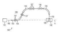
- FIG. 1illustrates an irradiation facility (system) including a gantry system
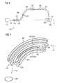
- FIG. 2illustrates a beam guidance magnet
- FIG. 3illustrates exit sites and angular deviations in a plane of the isocenter at right angles to the main beam direction
- FIG. 4illustrates a beam guidance magnet with two electrode pairs
- FIG. 5illustrates a beam guidance magnet with two electrode pairs
- FIG. 6illustrates electrode pairs with control voltages for horizontal and vertical deflection
- FIG. 7illustrates a beam guidance magnet with two correction coil pairs
- FIG. 8illustrates a beam guidance magnet in a side view with two correction coil pairs
- FIG. 9is a diagram according to FIG. 3 in which the scan curve in the plane of the isocenter is drawn.
- FIG. 1shows an irradiation facility 100 by which a beam of electrically charged particles (particle beam) 102 emerging from a particle source or accelerator 101 is deflected along a curved particle path with a gantry system.
- the particle beam 102may be a beam of C 6+ ions.
- the particle beam 102is guided inside a beam guidance tube 103 .
- a beam guidance plane 104is the curved path of the particle beam 102 .
- the particle beam 102is deflected (or, as the case may be, focused) several times from a direction predefined by the particle source or accelerator 101 from the particle beam's 102 original direction by a plurality of deflection magnets 105 and/or quadrupole magnets 107 .
- Deflection magnets 105 and/or quadrupole magnets 107 and further magnets, for example, scanner magnets 106are part of the gantry system which is rotatable around a specified rotation axis A.
- a gantry systemincludes a frame for mounting the corresponding magnets.
- the gantry systemmay direct the particle beam 102 into an isocenter 109 .
- An isocenter 109is an area in which the particle beam 102 intersects the gantry rotation axis A. During a rotation of the gantry system, the particle beam 102 runs consistently through the isocenter 109 .
- the isocenter 109is located inside an irradiation zone 108 . If an irradiation facility 100 is used, for example, for cancer treatment, a tumor or phantom that is to be irradiated with C 6+ ions, for example, is located in the area of the isocenter 109 .
- FIG. 2shows a beam guidance magnet in a side view.
- the beam guidance magnetmay be a 90° deflection magnet.
- the beam guidance magnetmay deflect the particle beam by 90°, for example.
- the beam guidance magnetmay include a plurality of coil systems.
- the coil systemmay include a first and second coil subsystem.
- FIG. 2shows the individual coils of a first and second coil subsystem.
- the first coil subsystemcomprises two main coils 201 .
- FIG. 4shows one of the two main coils.
- the corresponding second main coilwhich is arranged laterally reversed with respect to the beam guidance plane, lies congruent with the first main coil.
- the first main coils 201each have bent-up end parts 205 , 206 .
- the secondary coils 207are located between the bent-up end parts 205 , 206 .
- the main coils 201each have elongate side parts 203 along the particle path, while the secondary coils 207 each have largely flat, elongated side parts 208 .
- the end parts 205 , 206 of the main coils 201 , 202may be bent upward in such a way that they overlap with the arcuate end parts 209 , 210 of the secondary coils 207 in the projection into the beam guidance plane.
- the second coil subsystemincludes two second main coils 302 , 303 , which are each curved in a banana shape and are disposed in the area of the beam guidance plane between the first main coils 201 .
- the two second main coils 302 , 303each have a section close to the particle path and a side part distant from the particle path.
- the coil systemmay include main correction coils 301 arranged in the inner area of the secondary coil.
- a beam of electrically charged particles 101may be deflected into an isocenter 109 by the coil system shown in FIG. 2 .
- FIG. 3shows in the plane of the isocenter the exit sites (crosses) and angular deviations from an ideal vertical incident direction (arrows) when an uncorrected deflection magnet, as shown for example in FIG. 2 , is used for deflecting the particle beam.
- the deflection magnetincludes additional electrode pairs on the output side and inside the beam tube.
- the additional electrode pairsmay be placed under voltage in pairs individually for the horizontal and vertical deflection independently of the current feed to the magnet system of the deflection magnet in order to allow small angular corrections by means of an electric field.
- the electrode pairsmay be capacitors, such as parallel-plate capacitors.
- FIGS. 4 and 5show electrode pairs 700 , 702 .
- the coils of the deflection magnet surrounding the electrode pairs 700 , 702are shown transparently in order to allow a view onto the electrode pair.
- a first electrode pair 700enables the deflection of the particle beam in the y-direction (horizontal direction) while the second electrode pair 702 enables the deflection of the particle beam in the z-direction (vertical direction).
- the two electrode pairs 700 , 702may be driven simultaneously and according to strength in accordance with the necessary correction for both directions for the respective beam. Initially an increased spatial deviation can be associated with this. However, this can likewise be fully compensated by appropriate control of the scanner magnets (angular correction during injection of typically less than 1 mrad).
- the energy change in the ions when speeding through the electric correction fieldis negligibly small, since the field strength-path length product is small and the direction of the electric field is almost vertical to the movement direction of the ions.
- the field strength-path length productis associated only with a change in direction but not a change in velocity of the ions.
- the angular deviation for each beamwhich for treatment purposes has only a small extension relative to the aperture of the magnet (e.g. 1 to 5 mm beam diameter relative to 200 ⁇ 200 mm 2 aperture), can be fully corrected for each location within the aperture by the electric field that is built up between the electrode pairs 700 , 702 .
- a beam of small extensioncan exit precisely at each location within the aperture exactly in parallel and correct the unavoidable imaging errors of the magnet system.
- the magnet system of the main magnetshould already have satisfactory imaging characteristics, as shown in FIG. 3 .
- Remaining inaccuraciesmay be corrected. Greater deviations, for example, distortions of the beam spot (a beam with round cross-section could exit the deflection magnet with a slightly elliptical cross-section for example) cannot be corrected by the above device and method.
- the requirements in terms of the ion-optic characteristics with regard to the beam distortionsare relatively minor compared to angular and spatial deviations.
- the correction method and the deviceare suitable for magnet arrangements that include nonlinear materials such as ferromagnetic shields, which essentially cannot have optimal imaging characteristics for all ion energies simultaneously.
- the current feed to the magnet system and the scanner control for each scan rowmay be set such that the positive and negative angular deviations are of equal size in terms of absolute value.
- the drive voltages for each roware minimized symmetrically around zero and the absolute value of the voltage is reduced to a minimum.
- the absolute value of the electrode voltage and the risk of a flashoverare reduced.
- the use of an electric field for small angular correctionshas the advantage that correction may be performed quickly, since only small capacitances have to be recharged, which permits the voxel-by-voxel or pixel-by-pixel correction during the scanning.
- FIG. 6shows the driving of the electrode pairs 700 , 702 by control voltage for the horizontal and vertical deflection, respectively.
- the deflection magnetincludes additional correction coil pairs (for example, at the output of the magnet), which can be driven in pairs individually for the horizontal and vertical deflection independently of the current feed to the main magnets. Accordingly, a spatial deviation may be initially increased. The increased spatial deviation may be compensated by suitable control of the scanner magnets (angular correction during injection of typically less than 1 mrad).
- FIGS. 7 and 8show correction coil pairs.
- FIG. 7shows a first correction coil pair 800 for the deflection in the y-direction (horizontal direction) and a second correction coil pair 802 arranged at right angles thereto for the deflection in the z-direction (vertical direction).
- the correction coils 800 , 802may suppress the angular deviation for each beam, which for treatment purposes has only a small extension relative to the aperture of the magnet (e.g. 1 to 5 mm beam diameter relative to 200 ⁇ 200 mm 2 aperture), for each location within the aperture.
- the individually driven correction coil pairs 800 , 802 and suitable control of the scanner magnetsmay cause a beam of small extension to exit precisely at each location within the aperture exactly in parallel and correct the unavoidable imaging errors of the main magnet.
- the magnet system of the main magnetmay have satisfactory imaging characteristics, as shown in FIG. 3 .
- the remaining inaccuraciesmay be corrected all the more easily. Greater deviations, for example, distortions of the beam spot (a beam with round cross-section could exit the deflection magnet with a slightly elliptical cross-section for example) cannot be corrected by the above device and method.
- the requirements in terms of the ion-optic characteristics with regard to the beam distortionsare relatively minor compared to angular and spatial deviations.
- the correction method and the deviceare suitable for use in particular for magnet arrangements that include nonlinear materials such as ferromagnetic shields which essentially cannot have optimal imaging characteristics for all ion energies simultaneously.
- the first correction coil pair 800 for horizontal deflectionmay be omitted and the current feed to the main magnet is corrected. This saves on a correction coil pair 800 and its current source.
- the high inductance of the main magnetmay make it difficult to effect quick current changes due to the high voltages and the AC losses occurring in the superconductor (e.g., when a superconducting magnet is used).
- the current feed to the main magnetmay be set to the mean value of the correction current for a scan row (compare FIG. 9 ) and the correction performed from voxel to voxel by the horizontal first correction coil pair 800 .
- the correction coil pairs 800 , 802may include a strong inductive coupling of the correction coils and the coils of the main magnet. Quick current changes in the correction coils can then induce high voltages in the main coil system, which can then be corrected by the main coil system's current source.
- the high voltagesmay be counteracted by incorporating the drive signals for the current feed to the correction coils in accordance with the coupling to the main coil system as a correction variable into the regulation or control of the current source of the main coil system.
- an additional controlled voltage sourcecan equally be connected in series with the main coil system and the main coil current source, which voltage source compensates the induction voltage due to the correction coil current change in accordance with the control.
- the current regulation in the main coil systemmay be improved or made easier.
- a flux density of approximately 90 mTis required in the center of the first correction coil pair 800 , where the coils have a 1 m spacing and 0.5 m radius. This flux density is achieved for a magnetomotive force per coil of approximately 100 kA*turns.
- Each individual correction coil of the pair for horizontal deflection with a radius of 0.5 m and cross-section of 5 ⁇ 10 cm 2has an inductance of approximately 1.6 ⁇ H for one turn.
- correction coil pairs 800 , 802are normally conducting or superconducting can be assessed on the basis of the different loss contributions and the cooling concept of the overall magnet arrangement. Both are possible from the ion-optic viewpoint.
- FIG. 9shows the curve of a scanned particle beam along a y,z plane which is scanned in rows arranged in the y-direction.
Landscapes
- Physics & Mathematics (AREA)
- Engineering & Computer Science (AREA)
- Health & Medical Sciences (AREA)
- Spectroscopy & Molecular Physics (AREA)
- Biomedical Technology (AREA)
- High Energy & Nuclear Physics (AREA)
- General Engineering & Computer Science (AREA)
- Nuclear Medicine, Radiotherapy & Molecular Imaging (AREA)
- General Health & Medical Sciences (AREA)
- Public Health (AREA)
- Veterinary Medicine (AREA)
- Animal Behavior & Ethology (AREA)
- Life Sciences & Earth Sciences (AREA)
- Radiology & Medical Imaging (AREA)
- Pathology (AREA)
- Optics & Photonics (AREA)
- Plasma & Fusion (AREA)
- Radiation-Therapy Devices (AREA)
Abstract
Description
Claims (23)
Applications Claiming Priority (3)
| Application Number | Priority Date | Filing Date | Title |
|---|---|---|---|
| DE102007050035.3ADE102007050035B4 (en) | 2007-10-17 | 2007-10-17 | Apparatus and method for deflecting a jet of electrically charged particles onto a curved particle path |
| DEDE102007050035.3 | 2007-10-17 | ||
| DE102007050035 | 2007-10-17 |
Publications (2)
| Publication Number | Publication Date |
|---|---|
| US20090101832A1 US20090101832A1 (en) | 2009-04-23 |
| US7868301B2true US7868301B2 (en) | 2011-01-11 |
Family
ID=40458847
Family Applications (1)
| Application Number | Title | Priority Date | Filing Date |
|---|---|---|---|
| US12/249,531Active2029-07-18US7868301B2 (en) | 2007-10-17 | 2008-10-10 | Deflecting a beam of electrically charged particles onto a curved particle path |
Country Status (2)
| Country | Link |
|---|---|
| US (1) | US7868301B2 (en) |
| DE (1) | DE102007050035B4 (en) |
Cited By (27)
| Publication number | Priority date | Publication date | Assignee | Title |
|---|---|---|---|---|
| US20090140671A1 (en)* | 2007-11-30 | 2009-06-04 | O'neal Iii Charles D | Matching a resonant frequency of a resonant cavity to a frequency of an input voltage |
| US20090200483A1 (en)* | 2005-11-18 | 2009-08-13 | Still River Systems Incorporated | Inner Gantry |
| US20100045213A1 (en)* | 2004-07-21 | 2010-02-25 | Still River Systems, Inc. | Programmable Radio Frequency Waveform Generator for a Synchrocyclotron |
| US8581523B2 (en) | 2007-11-30 | 2013-11-12 | Mevion Medical Systems, Inc. | Interrupted particle source |
| US8791656B1 (en) | 2013-05-31 | 2014-07-29 | Mevion Medical Systems, Inc. | Active return system |
| US8927950B2 (en) | 2012-09-28 | 2015-01-06 | Mevion Medical Systems, Inc. | Focusing a particle beam |
| US20150123007A1 (en)* | 2012-05-31 | 2015-05-07 | Siemens Aktiengesellschaft | Deflection plate and deflection device for deflecting charged particles |
| US9155186B2 (en) | 2012-09-28 | 2015-10-06 | Mevion Medical Systems, Inc. | Focusing a particle beam using magnetic field flutter |
| US9185789B2 (en) | 2012-09-28 | 2015-11-10 | Mevion Medical Systems, Inc. | Magnetic shims to alter magnetic fields |
| US9274067B2 (en) | 2011-03-07 | 2016-03-01 | Loma Linda University Medical Center | Systems, devices and methods related to calibration of a proton computed tomography scanner |
| US9301384B2 (en) | 2012-09-28 | 2016-03-29 | Mevion Medical Systems, Inc. | Adjusting energy of a particle beam |
| US9545528B2 (en) | 2012-09-28 | 2017-01-17 | Mevion Medical Systems, Inc. | Controlling particle therapy |
| US9622335B2 (en) | 2012-09-28 | 2017-04-11 | Mevion Medical Systems, Inc. | Magnetic field regenerator |
| US9661736B2 (en) | 2014-02-20 | 2017-05-23 | Mevion Medical Systems, Inc. | Scanning system for a particle therapy system |
| US9681531B2 (en) | 2012-09-28 | 2017-06-13 | Mevion Medical Systems, Inc. | Control system for a particle accelerator |
| US9723705B2 (en) | 2012-09-28 | 2017-08-01 | Mevion Medical Systems, Inc. | Controlling intensity of a particle beam |
| US9730308B2 (en) | 2013-06-12 | 2017-08-08 | Mevion Medical Systems, Inc. | Particle accelerator that produces charged particles having variable energies |
| US9950194B2 (en) | 2014-09-09 | 2018-04-24 | Mevion Medical Systems, Inc. | Patient positioning system |
| US9962560B2 (en) | 2013-12-20 | 2018-05-08 | Mevion Medical Systems, Inc. | Collimator and energy degrader |
| US10254739B2 (en) | 2012-09-28 | 2019-04-09 | Mevion Medical Systems, Inc. | Coil positioning system |
| US10258810B2 (en) | 2013-09-27 | 2019-04-16 | Mevion Medical Systems, Inc. | Particle beam scanning |
| US10646728B2 (en) | 2015-11-10 | 2020-05-12 | Mevion Medical Systems, Inc. | Adaptive aperture |
| US10653892B2 (en) | 2017-06-30 | 2020-05-19 | Mevion Medical Systems, Inc. | Configurable collimator controlled using linear motors |
| US10675487B2 (en) | 2013-12-20 | 2020-06-09 | Mevion Medical Systems, Inc. | Energy degrader enabling high-speed energy switching |
| US10925147B2 (en) | 2016-07-08 | 2021-02-16 | Mevion Medical Systems, Inc. | Treatment planning |
| US11103730B2 (en) | 2017-02-23 | 2021-08-31 | Mevion Medical Systems, Inc. | Automated treatment in particle therapy |
| US11291861B2 (en) | 2019-03-08 | 2022-04-05 | Mevion Medical Systems, Inc. | Delivery of radiation by column and generating a treatment plan therefor |
Families Citing this family (8)
| Publication number | Priority date | Publication date | Assignee | Title |
|---|---|---|---|---|
| CN102208226B (en)* | 2011-05-10 | 2013-01-16 | 中国科学院近代物理研究所 | High-accuracy three-combination quadrupole lens |
| JP6328487B2 (en)* | 2014-05-20 | 2018-05-23 | 住友重機械工業株式会社 | Superconducting electromagnet and charged particle beam therapy system |
| WO2016067820A1 (en)* | 2014-10-28 | 2016-05-06 | 国立研究開発法人 放射線医学総合研究所 | Charged particle beam irradiation device |
| JP6613466B2 (en)* | 2014-10-28 | 2019-12-04 | 国立研究開発法人量子科学技術研究開発機構 | Charged particle beam irradiation equipment |
| JP6529832B2 (en)* | 2015-06-15 | 2019-06-12 | 住友重機械工業株式会社 | Charged particle beam therapy system |
| CN106139419B (en)* | 2016-07-29 | 2022-10-28 | 中国原子能科学研究院 | Rotating frame for treating tumors |
| WO2022178218A1 (en) | 2021-02-19 | 2022-08-25 | Mevion Medical Systems, Inc. | Gantry for a particle therapy system |
| WO2025155696A1 (en)* | 2024-01-16 | 2025-07-24 | Ohio State Innovation Foundation | Portable liquid helium-free mri-guided proton therapy system |
Citations (8)
| Publication number | Priority date | Publication date | Assignee | Title |
|---|---|---|---|---|
| DE19907771A1 (en) | 1999-02-19 | 2000-08-31 | Schwerionenforsch Gmbh | Method for checking the radiation control unit of an ion beam therapy system |
| EP1045399A1 (en) | 1999-04-12 | 2000-10-18 | GSI Gesellschaft für Schwerionenforschung mbH | Device and method for controlling a raster scanner in ion theraphy |
| DE10057824A1 (en) | 2000-11-21 | 2002-06-06 | Schwerionenforsch Gmbh | Device and method for adjusting an ion beam spot size in tumor radiation |
| DE102005041122B3 (en) | 2005-08-30 | 2007-05-31 | Siemens Ag | Gantry system for a particle therapy system, particle therapy system and irradiation method for a particle therapy system with such a gantry system |
| US20080315113A1 (en)* | 2007-06-21 | 2008-12-25 | Dirk Diehl | Beam guidance magnet |
| US20090091409A1 (en)* | 2006-04-21 | 2009-04-09 | Gunter Ries | Curved beam control magnet |
| US20090090871A1 (en)* | 2007-09-28 | 2009-04-09 | Dirk Diehl | Radiation treatment system with a beam control magnet |
| US20090321654A1 (en)* | 2007-05-04 | 2009-12-31 | Dirk Diehl | Beam guiding magnet for deflecting a particle beam |
- 2007
- 2007-10-17DEDE102007050035.3Apatent/DE102007050035B4/enactiveActive
- 2008
- 2008-10-10USUS12/249,531patent/US7868301B2/enactiveActive
Patent Citations (9)
| Publication number | Priority date | Publication date | Assignee | Title |
|---|---|---|---|---|
| DE19907771A1 (en) | 1999-02-19 | 2000-08-31 | Schwerionenforsch Gmbh | Method for checking the radiation control unit of an ion beam therapy system |
| EP1045399A1 (en) | 1999-04-12 | 2000-10-18 | GSI Gesellschaft für Schwerionenforschung mbH | Device and method for controlling a raster scanner in ion theraphy |
| US6677597B1 (en) | 1999-04-12 | 2004-01-13 | Gesellschaft Fuer Schwerionenforschung Mbh | Device and method for controlling a raster scanner in ion-beam therapy |
| DE10057824A1 (en) | 2000-11-21 | 2002-06-06 | Schwerionenforsch Gmbh | Device and method for adjusting an ion beam spot size in tumor radiation |
| DE102005041122B3 (en) | 2005-08-30 | 2007-05-31 | Siemens Ag | Gantry system for a particle therapy system, particle therapy system and irradiation method for a particle therapy system with such a gantry system |
| US20090091409A1 (en)* | 2006-04-21 | 2009-04-09 | Gunter Ries | Curved beam control magnet |
| US20090321654A1 (en)* | 2007-05-04 | 2009-12-31 | Dirk Diehl | Beam guiding magnet for deflecting a particle beam |
| US20080315113A1 (en)* | 2007-06-21 | 2008-12-25 | Dirk Diehl | Beam guidance magnet |
| US20090090871A1 (en)* | 2007-09-28 | 2009-04-09 | Dirk Diehl | Radiation treatment system with a beam control magnet |
Non-Patent Citations (1)
| Title |
|---|
| German Office Action dated Aug. 4, 2008 with English translation. |
Cited By (50)
| Publication number | Priority date | Publication date | Assignee | Title |
|---|---|---|---|---|
| USRE48047E1 (en) | 2004-07-21 | 2020-06-09 | Mevion Medical Systems, Inc. | Programmable radio frequency waveform generator for a synchrocyclotron |
| US8952634B2 (en) | 2004-07-21 | 2015-02-10 | Mevion Medical Systems, Inc. | Programmable radio frequency waveform generator for a synchrocyclotron |
| US20100045213A1 (en)* | 2004-07-21 | 2010-02-25 | Still River Systems, Inc. | Programmable Radio Frequency Waveform Generator for a Synchrocyclotron |
| US8344340B2 (en) | 2005-11-18 | 2013-01-01 | Mevion Medical Systems, Inc. | Inner gantry |
| US8907311B2 (en) | 2005-11-18 | 2014-12-09 | Mevion Medical Systems, Inc. | Charged particle radiation therapy |
| US20090200483A1 (en)* | 2005-11-18 | 2009-08-13 | Still River Systems Incorporated | Inner Gantry |
| US8581523B2 (en) | 2007-11-30 | 2013-11-12 | Mevion Medical Systems, Inc. | Interrupted particle source |
| US8933650B2 (en) | 2007-11-30 | 2015-01-13 | Mevion Medical Systems, Inc. | Matching a resonant frequency of a resonant cavity to a frequency of an input voltage |
| US8970137B2 (en) | 2007-11-30 | 2015-03-03 | Mevion Medical Systems, Inc. | Interrupted particle source |
| US20090140671A1 (en)* | 2007-11-30 | 2009-06-04 | O'neal Iii Charles D | Matching a resonant frequency of a resonant cavity to a frequency of an input voltage |
| USRE48317E1 (en) | 2007-11-30 | 2020-11-17 | Mevion Medical Systems, Inc. | Interrupted particle source |
| US9880301B2 (en) | 2011-03-07 | 2018-01-30 | Loma Linda University Medical Center | Systems, devices and methods related to calibration of a proton computed tomography scanner |
| US9274067B2 (en) | 2011-03-07 | 2016-03-01 | Loma Linda University Medical Center | Systems, devices and methods related to calibration of a proton computed tomography scanner |
| US9312092B2 (en)* | 2012-05-31 | 2016-04-12 | Siemens Aktiengesellschaft | Deflection plate and deflection device for deflecting charged particles |
| US20150123007A1 (en)* | 2012-05-31 | 2015-05-07 | Siemens Aktiengesellschaft | Deflection plate and deflection device for deflecting charged particles |
| US8927950B2 (en) | 2012-09-28 | 2015-01-06 | Mevion Medical Systems, Inc. | Focusing a particle beam |
| US9301384B2 (en) | 2012-09-28 | 2016-03-29 | Mevion Medical Systems, Inc. | Adjusting energy of a particle beam |
| US9545528B2 (en) | 2012-09-28 | 2017-01-17 | Mevion Medical Systems, Inc. | Controlling particle therapy |
| US9622335B2 (en) | 2012-09-28 | 2017-04-11 | Mevion Medical Systems, Inc. | Magnetic field regenerator |
| US9185789B2 (en) | 2012-09-28 | 2015-11-10 | Mevion Medical Systems, Inc. | Magnetic shims to alter magnetic fields |
| US9681531B2 (en) | 2012-09-28 | 2017-06-13 | Mevion Medical Systems, Inc. | Control system for a particle accelerator |
| US9706636B2 (en) | 2012-09-28 | 2017-07-11 | Mevion Medical Systems, Inc. | Adjusting energy of a particle beam |
| US9723705B2 (en) | 2012-09-28 | 2017-08-01 | Mevion Medical Systems, Inc. | Controlling intensity of a particle beam |
| US9155186B2 (en) | 2012-09-28 | 2015-10-06 | Mevion Medical Systems, Inc. | Focusing a particle beam using magnetic field flutter |
| US10254739B2 (en) | 2012-09-28 | 2019-04-09 | Mevion Medical Systems, Inc. | Coil positioning system |
| US10368429B2 (en) | 2012-09-28 | 2019-07-30 | Mevion Medical Systems, Inc. | Magnetic field regenerator |
| US10155124B2 (en) | 2012-09-28 | 2018-12-18 | Mevion Medical Systems, Inc. | Controlling particle therapy |
| US8791656B1 (en) | 2013-05-31 | 2014-07-29 | Mevion Medical Systems, Inc. | Active return system |
| US9730308B2 (en) | 2013-06-12 | 2017-08-08 | Mevion Medical Systems, Inc. | Particle accelerator that produces charged particles having variable energies |
| US10456591B2 (en) | 2013-09-27 | 2019-10-29 | Mevion Medical Systems, Inc. | Particle beam scanning |
| US10258810B2 (en) | 2013-09-27 | 2019-04-16 | Mevion Medical Systems, Inc. | Particle beam scanning |
| US9962560B2 (en) | 2013-12-20 | 2018-05-08 | Mevion Medical Systems, Inc. | Collimator and energy degrader |
| US10675487B2 (en) | 2013-12-20 | 2020-06-09 | Mevion Medical Systems, Inc. | Energy degrader enabling high-speed energy switching |
| US10434331B2 (en) | 2014-02-20 | 2019-10-08 | Mevion Medical Systems, Inc. | Scanning system |
| US9661736B2 (en) | 2014-02-20 | 2017-05-23 | Mevion Medical Systems, Inc. | Scanning system for a particle therapy system |
| US11717700B2 (en) | 2014-02-20 | 2023-08-08 | Mevion Medical Systems, Inc. | Scanning system |
| US9950194B2 (en) | 2014-09-09 | 2018-04-24 | Mevion Medical Systems, Inc. | Patient positioning system |
| US11213697B2 (en) | 2015-11-10 | 2022-01-04 | Mevion Medical Systems, Inc. | Adaptive aperture |
| US10646728B2 (en) | 2015-11-10 | 2020-05-12 | Mevion Medical Systems, Inc. | Adaptive aperture |
| US11786754B2 (en) | 2015-11-10 | 2023-10-17 | Mevion Medical Systems, Inc. | Adaptive aperture |
| US10786689B2 (en) | 2015-11-10 | 2020-09-29 | Mevion Medical Systems, Inc. | Adaptive aperture |
| US10925147B2 (en) | 2016-07-08 | 2021-02-16 | Mevion Medical Systems, Inc. | Treatment planning |
| US12150235B2 (en) | 2016-07-08 | 2024-11-19 | Mevion Medical Systems, Inc. | Treatment planning |
| US11103730B2 (en) | 2017-02-23 | 2021-08-31 | Mevion Medical Systems, Inc. | Automated treatment in particle therapy |
| US10653892B2 (en) | 2017-06-30 | 2020-05-19 | Mevion Medical Systems, Inc. | Configurable collimator controlled using linear motors |
| US11291861B2 (en) | 2019-03-08 | 2022-04-05 | Mevion Medical Systems, Inc. | Delivery of radiation by column and generating a treatment plan therefor |
| US11311746B2 (en) | 2019-03-08 | 2022-04-26 | Mevion Medical Systems, Inc. | Collimator and energy degrader for a particle therapy system |
| US11717703B2 (en) | 2019-03-08 | 2023-08-08 | Mevion Medical Systems, Inc. | Delivery of radiation by column and generating a treatment plan therefor |
| US12161885B2 (en) | 2019-03-08 | 2024-12-10 | Mevion Medical Systems, Inc. | Delivery of radiation by column and generating a treatment plan therefor |
| US12168147B2 (en) | 2019-03-08 | 2024-12-17 | Mevion Medical Systems, Inc. | Collimator and energy degrader for a particle therapy system |
Also Published As
| Publication number | Publication date |
|---|---|
| DE102007050035B4 (en) | 2015-10-08 |
| US20090101832A1 (en) | 2009-04-23 |
| DE102007050035A1 (en) | 2009-04-23 |
Similar Documents
| Publication | Publication Date | Title |
|---|---|---|
| US7868301B2 (en) | Deflecting a beam of electrically charged particles onto a curved particle path | |
| KR101974425B1 (en) | Focusing magnet and charged particle irradiation apparatus | |
| US8487269B2 (en) | Combined radiation therapy and magnetic resonance unit | |
| US8378312B1 (en) | System, apparatus and method for deflecting a particle beam | |
| US20210085999A1 (en) | Apparatus and methods for magnetic control of radiation electron beam | |
| EP1501603B1 (en) | Device for irradiation therapy with charged particles | |
| US7812319B2 (en) | Beam guiding magnet for deflecting a particle beam | |
| US7432516B2 (en) | Rapid cycling medical synchrotron and beam delivery system | |
| US8405044B2 (en) | Achromatically bending a beam of charged particles by about ninety degrees | |
| US20030164458A1 (en) | Beam scanning system for a heavy ion gantry | |
| US11110299B2 (en) | Proton-arc beam delivery system | |
| KR20050083810A (en) | Electron accelerator and radiotherapy apparatus using same | |
| US10195465B2 (en) | Method and apparatus for controlled pencil beam therapy with rapid beam compensation | |
| EP3308834A1 (en) | Particle therapy apparatus comprising an mri | |
| US4063098A (en) | Beam scanning system | |
| JP2019180654A (en) | Convergent electromagnet and charged particle beam irradiation device | |
| US20150340141A1 (en) | Superconductive electromagnet device | |
| CN113470920B (en) | Superconducting electromagnet device and charged particle beam irradiation device | |
| JP2021153759A (en) | Electric charge particle beam radiation device | |
| US9067065B2 (en) | Particle beam irradiation apparatus and particle beam therapy system utilizing a beam position monitor to provide feedback adjustments based on the beam position | |
| US20090090871A1 (en) | Radiation treatment system with a beam control magnet | |
| US7315034B2 (en) | Irradiation system with ion beam/charged particle beam | |
| JP7293042B2 (en) | Charged particle beam irradiation device and charged particle beam irradiation method | |
| JP2025527432A (en) | Bent Magnet | |
| US20080116390A1 (en) | Delivery of a Charged Particle Beam |
Legal Events
| Date | Code | Title | Description |
|---|---|---|---|
| AS | Assignment | Owner name:SIEMENS AKTIENGESELLSCHAFT, GERMANY Free format text:ASSIGNMENT OF ASSIGNORS INTEREST;ASSIGNOR:DIEHL, DIRK;REEL/FRAME:021878/0717 Effective date:20081103 | |
| STCF | Information on status: patent grant | Free format text:PATENTED CASE | |
| FPAY | Fee payment | Year of fee payment:4 | |
| AS | Assignment | Owner name:SIEMENS HEALTHCARE GMBH, GERMANY Free format text:ASSIGNMENT OF ASSIGNORS INTEREST;ASSIGNOR:SIEMENS AKTIENGESELLSCHAFT;REEL/FRAME:039271/0561 Effective date:20160610 | |
| MAFP | Maintenance fee payment | Free format text:PAYMENT OF MAINTENANCE FEE, 8TH YEAR, LARGE ENTITY (ORIGINAL EVENT CODE: M1552) Year of fee payment:8 | |
| AS | Assignment | Owner name:VARIAN MEDICAL SYSTEMS PARTICLE THERAPY GMBH, GERMANY Free format text:ASSIGNMENT OF ASSIGNORS INTEREST;ASSIGNOR:SIEMENS HEALTHCARE GMBH;REEL/FRAME:055648/0772 Effective date:20170710 | |
| AS | Assignment | Owner name:VARIAN MEDICAL SYSTEMS PARTICLE THERAPY GMBH & CO. KG, GERMANY Free format text:CHANGE OF NAME;ASSIGNOR:VARIAN MEDICAL SYSTEMS PARTICLE THERAPY GMBH;REEL/FRAME:056998/0015 Effective date:20201218 | |
| MAFP | Maintenance fee payment | Free format text:PAYMENT OF MAINTENANCE FEE, 12TH YEAR, LARGE ENTITY (ORIGINAL EVENT CODE: M1553); ENTITY STATUS OF PATENT OWNER: LARGE ENTITY Year of fee payment:12 |