US7867891B2 - Dual metal interconnects for improved gap-fill, reliability, and reduced capacitance - Google Patents
Dual metal interconnects for improved gap-fill, reliability, and reduced capacitanceDownload PDFInfo
- Publication number
- US7867891B2 US7867891B2US12/316,304US31630408AUS7867891B2US 7867891 B2US7867891 B2US 7867891B2US 31630408 AUS31630408 AUS 31630408AUS 7867891 B2US7867891 B2US 7867891B2
- Authority
- US
- United States
- Prior art keywords
- interconnect
- refractory
- opening
- trench
- layer
- Prior art date
- Legal status (The legal status is an assumption and is not a legal conclusion. Google has not performed a legal analysis and makes no representation as to the accuracy of the status listed.)
- Active
Links
- 229910052751metalInorganic materials0.000titleclaimsdescription62
- 239000002184metalSubstances0.000titleclaimsdescription62
- 230000009977dual effectEffects0.000titleclaimsdescription16
- 238000000034methodMethods0.000claimsdescription57
- 230000008569processEffects0.000claimsdescription31
- 230000004888barrier functionEffects0.000claimsdescription27
- 238000000151depositionMethods0.000claimsdescription16
- PXHVJJICTQNCMI-UHFFFAOYSA-NNickelChemical compound[Ni]PXHVJJICTQNCMI-UHFFFAOYSA-N0.000claimsdescription12
- KDLHZDBZIXYQEI-UHFFFAOYSA-NPalladiumChemical compound[Pd]KDLHZDBZIXYQEI-UHFFFAOYSA-N0.000claimsdescription12
- BASFCYQUMIYNBI-UHFFFAOYSA-NplatinumChemical compound[Pt]BASFCYQUMIYNBI-UHFFFAOYSA-N0.000claimsdescription12
- 150000002739metalsChemical class0.000claimsdescription10
- 239000000758substrateSubstances0.000claimsdescription10
- 238000005240physical vapour depositionMethods0.000claimsdescription9
- 239000003870refractory metalSubstances0.000claimsdescription9
- XKRFYHLGVUSROY-UHFFFAOYSA-NArgonChemical compound[Ar]XKRFYHLGVUSROY-UHFFFAOYSA-N0.000claimsdescription6
- 229910045601alloyInorganic materials0.000claimsdescription6
- 239000000956alloySubstances0.000claimsdescription6
- 239000000203mixtureSubstances0.000claimsdescription6
- 230000008021depositionEffects0.000claimsdescription5
- 239000003989dielectric materialSubstances0.000claimsdescription5
- 230000037361pathwayEffects0.000claimsdescription5
- KJTLSVCANCCWHF-UHFFFAOYSA-NRutheniumChemical compound[Ru]KJTLSVCANCCWHF-UHFFFAOYSA-N0.000claimsdescription4
- 229910017052cobaltInorganic materials0.000claimsdescription4
- 239000010941cobaltSubstances0.000claimsdescription4
- GUTLYIVDDKVIGB-UHFFFAOYSA-Ncobalt atomChemical compound[Co]GUTLYIVDDKVIGB-UHFFFAOYSA-N0.000claimsdescription4
- 229910052759nickelInorganic materials0.000claimsdescription4
- 229910052763palladiumInorganic materials0.000claimsdescription4
- 229910052697platinumInorganic materials0.000claimsdescription4
- 229910052707rutheniumInorganic materials0.000claimsdescription4
- WFKWXMTUELFFGS-UHFFFAOYSA-NtungstenChemical compound[W]WFKWXMTUELFFGS-UHFFFAOYSA-N0.000claimsdescription4
- 229910052721tungstenInorganic materials0.000claimsdescription4
- 239000010937tungstenSubstances0.000claimsdescription4
- ZOXJGFHDIHLPTG-UHFFFAOYSA-NBoronChemical compound[B]ZOXJGFHDIHLPTG-UHFFFAOYSA-N0.000claimsdescription3
- OAICVXFJPJFONN-UHFFFAOYSA-NPhosphorusChemical compound[P]OAICVXFJPJFONN-UHFFFAOYSA-N0.000claimsdescription3
- 229910052786argonInorganic materials0.000claimsdescription3
- 229910052796boronInorganic materials0.000claimsdescription3
- 239000001307heliumSubstances0.000claimsdescription3
- 229910052734heliumInorganic materials0.000claimsdescription3
- SWQJXJOGLNCZEY-UHFFFAOYSA-Nhelium atomChemical compound[He]SWQJXJOGLNCZEY-UHFFFAOYSA-N0.000claimsdescription3
- 239000001257hydrogenSubstances0.000claimsdescription3
- 229910052739hydrogenInorganic materials0.000claimsdescription3
- 125000004435hydrogen atomChemical class[H]*0.000claimsdescription3
- 238000010849ion bombardmentMethods0.000claimsdescription3
- 229910052698phosphorusInorganic materials0.000claimsdescription3
- 239000011574phosphorusSubstances0.000claimsdescription3
- 238000007772electroless platingMethods0.000claimsdescription2
- 238000005530etchingMethods0.000claimsdescription2
- 238000000231atomic layer depositionMethods0.000claims2
- 239000011819refractory materialSubstances0.000claims2
- 239000010410layerSubstances0.000description77
- 239000000463materialSubstances0.000description14
- 238000004519manufacturing processMethods0.000description10
- VYPSYNLAJGMNEJ-UHFFFAOYSA-NSilicium dioxideChemical compoundO=[Si]=OVYPSYNLAJGMNEJ-UHFFFAOYSA-N0.000description9
- 239000010949copperSubstances0.000description8
- 239000011229interlayerSubstances0.000description7
- 238000004377microelectronicMethods0.000description7
- 230000015572biosynthetic processEffects0.000description6
- 229910052581Si3N4Inorganic materials0.000description5
- XUIMIQQOPSSXEZ-UHFFFAOYSA-NSiliconChemical compound[Si]XUIMIQQOPSSXEZ-UHFFFAOYSA-N0.000description5
- 239000004020conductorSubstances0.000description5
- 229910052710siliconInorganic materials0.000description5
- 239000010703siliconSubstances0.000description5
- HQVNEWCFYHHQES-UHFFFAOYSA-Nsilicon nitrideChemical compoundN12[Si]34N5[Si]62N3[Si]51N64HQVNEWCFYHHQES-UHFFFAOYSA-N0.000description5
- 229910052802copperInorganic materials0.000description4
- 238000005137deposition processMethods0.000description4
- 229910052814silicon oxideInorganic materials0.000description4
- RYGMFSIKBFXOCR-UHFFFAOYSA-NCopperChemical compound[Cu]RYGMFSIKBFXOCR-UHFFFAOYSA-N0.000description3
- 229920002120photoresistant polymerPolymers0.000description3
- 229910052454barium strontium titanateInorganic materials0.000description2
- 239000003054catalystSubstances0.000description2
- 238000009713electroplatingMethods0.000description2
- MRELNEQAGSRDBK-UHFFFAOYSA-Nlanthanum(3+);oxygen(2-)Chemical compound[O-2].[O-2].[O-2].[La+3].[La+3]MRELNEQAGSRDBK-UHFFFAOYSA-N0.000description2
- 229910052451lead zirconate titanateInorganic materials0.000description2
- 238000001465metallisationMethods0.000description2
- 238000000059patterningMethods0.000description2
- 238000000623plasma-assisted chemical vapour depositionMethods0.000description2
- 230000009467reductionEffects0.000description2
- 239000000377silicon dioxideSubstances0.000description2
- JBRZTFJDHDCESZ-UHFFFAOYSA-NAsGaChemical compound[As]#[Ga]JBRZTFJDHDCESZ-UHFFFAOYSA-N0.000description1
- 229910000881Cu alloyInorganic materials0.000description1
- BQCADISMDOOEFD-UHFFFAOYSA-NSilverChemical compound[Ag]BQCADISMDOOEFD-UHFFFAOYSA-N0.000description1
- GWEVSGVZZGPLCZ-UHFFFAOYSA-NTitan oxideChemical compoundO=[Ti]=OGWEVSGVZZGPLCZ-UHFFFAOYSA-N0.000description1
- 229910052782aluminiumInorganic materials0.000description1
- XAGFODPZIPBFFR-UHFFFAOYSA-NaluminiumChemical compound[Al]XAGFODPZIPBFFR-UHFFFAOYSA-N0.000description1
- 230000006399behaviorEffects0.000description1
- 239000003990capacitorSubstances0.000description1
- 230000003197catalytic effectEffects0.000description1
- 239000003638chemical reducing agentSubstances0.000description1
- 238000005229chemical vapour depositionMethods0.000description1
- 230000001010compromised effectEffects0.000description1
- 239000000356contaminantSubstances0.000description1
- 230000007547defectEffects0.000description1
- 230000001419dependent effectEffects0.000description1
- 238000009792diffusion processMethods0.000description1
- 230000008030eliminationEffects0.000description1
- 238000003379elimination reactionMethods0.000description1
- 230000003628erosive effectEffects0.000description1
- 229920002313fluoropolymerPolymers0.000description1
- 239000004811fluoropolymerSubstances0.000description1
- 229910000449hafnium oxideInorganic materials0.000description1
- WIHZLLGSGQNAGK-UHFFFAOYSA-Nhafnium(4+);oxygen(2-)Chemical compound[O-2].[O-2].[Hf+4]WIHZLLGSGQNAGK-UHFFFAOYSA-N0.000description1
- 230000020169heat generationEffects0.000description1
- WPYVAWXEWQSOGY-UHFFFAOYSA-Nindium antimonideChemical compound[Sb]#[In]WPYVAWXEWQSOGY-UHFFFAOYSA-N0.000description1
- 239000012212insulatorSubstances0.000description1
- 230000001788irregularEffects0.000description1
- HFGPZNIAWCZYJU-UHFFFAOYSA-Nlead zirconate titanateChemical compound[O-2].[O-2].[O-2].[O-2].[O-2].[Ti+4].[Zr+4].[Pb+2]HFGPZNIAWCZYJU-UHFFFAOYSA-N0.000description1
- 238000001459lithographyMethods0.000description1
- 238000012986modificationMethods0.000description1
- 230000004048modificationEffects0.000description1
- 230000006855networkingEffects0.000description1
- 230000006911nucleationEffects0.000description1
- 238000010899nucleationMethods0.000description1
- 230000003287optical effectEffects0.000description1
- TWNQGVIAIRXVLR-UHFFFAOYSA-Noxo(oxoalumanyloxy)alumaneChemical compoundO=[Al]O[Al]=OTWNQGVIAIRXVLR-UHFFFAOYSA-N0.000description1
- BPUBBGLMJRNUCC-UHFFFAOYSA-Noxygen(2-);tantalum(5+)Chemical compound[O-2].[O-2].[O-2].[O-2].[O-2].[Ta+5].[Ta+5]BPUBBGLMJRNUCC-UHFFFAOYSA-N0.000description1
- RVTZCBVAJQQJTK-UHFFFAOYSA-Noxygen(2-);zirconium(4+)Chemical compound[O-2].[O-2].[Zr+4]RVTZCBVAJQQJTK-UHFFFAOYSA-N0.000description1
- 229910021420polycrystalline siliconInorganic materials0.000description1
- 229920000642polymerPolymers0.000description1
- 229920005591polysiliconPolymers0.000description1
- 229910021426porous siliconInorganic materials0.000description1
- 150000003839saltsChemical class0.000description1
- 239000004065semiconductorSubstances0.000description1
- 235000012239silicon dioxideNutrition0.000description1
- 229910052709silverInorganic materials0.000description1
- 239000004332silverSubstances0.000description1
- 238000009751slip formingMethods0.000description1
- 230000002269spontaneous effectEffects0.000description1
- 238000004544sputter depositionMethods0.000description1
- 238000003860storageMethods0.000description1
- 239000000126substanceSubstances0.000description1
- 238000006467substitution reactionMethods0.000description1
- 229910052715tantalumInorganic materials0.000description1
- GUVRBAGPIYLISA-UHFFFAOYSA-Ntantalum atomChemical compound[Ta]GUVRBAGPIYLISA-UHFFFAOYSA-N0.000description1
- MZLGASXMSKOWSE-UHFFFAOYSA-Ntantalum nitrideChemical compound[Ta]#NMZLGASXMSKOWSE-UHFFFAOYSA-N0.000description1
- 229910001936tantalum oxideInorganic materials0.000description1
- 238000002207thermal evaporationMethods0.000description1
- OGIDPMRJRNCKJF-UHFFFAOYSA-Ntitanium oxideInorganic materials[Ti]=OOGIDPMRJRNCKJF-UHFFFAOYSA-N0.000description1
- 235000012431wafersNutrition0.000description1
- 229910001928zirconium oxideInorganic materials0.000description1
Images


Classifications
- H—ELECTRICITY
- H01—ELECTRIC ELEMENTS
- H01L—SEMICONDUCTOR DEVICES NOT COVERED BY CLASS H10
- H01L21/00—Processes or apparatus adapted for the manufacture or treatment of semiconductor or solid state devices or of parts thereof
- H01L21/02—Manufacture or treatment of semiconductor devices or of parts thereof
- H01L21/04—Manufacture or treatment of semiconductor devices or of parts thereof the devices having potential barriers, e.g. a PN junction, depletion layer or carrier concentration layer
- H01L21/18—Manufacture or treatment of semiconductor devices or of parts thereof the devices having potential barriers, e.g. a PN junction, depletion layer or carrier concentration layer the devices having semiconductor bodies comprising elements of Group IV of the Periodic Table or AIIIBV compounds with or without impurities, e.g. doping materials
- H01L21/28—Manufacture of electrodes on semiconductor bodies using processes or apparatus not provided for in groups H01L21/20 - H01L21/268
- H—ELECTRICITY
- H01—ELECTRIC ELEMENTS
- H01L—SEMICONDUCTOR DEVICES NOT COVERED BY CLASS H10
- H01L21/00—Processes or apparatus adapted for the manufacture or treatment of semiconductor or solid state devices or of parts thereof
- H01L21/70—Manufacture or treatment of devices consisting of a plurality of solid state components formed in or on a common substrate or of parts thereof; Manufacture of integrated circuit devices or of parts thereof
- H01L21/71—Manufacture of specific parts of devices defined in group H01L21/70
- H01L21/768—Applying interconnections to be used for carrying current between separate components within a device comprising conductors and dielectrics
- H01L21/76838—Applying interconnections to be used for carrying current between separate components within a device comprising conductors and dielectrics characterised by the formation and the after-treatment of the conductors
- H01L21/76877—Filling of holes, grooves or trenches, e.g. vias, with conductive material
- H01L21/76879—Filling of holes, grooves or trenches, e.g. vias, with conductive material by selective deposition of conductive material in the vias, e.g. selective C.V.D. on semiconductor material, plating
- H—ELECTRICITY
- H01—ELECTRIC ELEMENTS
- H01L—SEMICONDUCTOR DEVICES NOT COVERED BY CLASS H10
- H01L21/00—Processes or apparatus adapted for the manufacture or treatment of semiconductor or solid state devices or of parts thereof
- H01L21/02—Manufacture or treatment of semiconductor devices or of parts thereof
- H01L21/04—Manufacture or treatment of semiconductor devices or of parts thereof the devices having potential barriers, e.g. a PN junction, depletion layer or carrier concentration layer
- H01L21/18—Manufacture or treatment of semiconductor devices or of parts thereof the devices having potential barriers, e.g. a PN junction, depletion layer or carrier concentration layer the devices having semiconductor bodies comprising elements of Group IV of the Periodic Table or AIIIBV compounds with or without impurities, e.g. doping materials
- H01L21/30—Treatment of semiconductor bodies using processes or apparatus not provided for in groups H01L21/20 - H01L21/26
- H01L21/31—Treatment of semiconductor bodies using processes or apparatus not provided for in groups H01L21/20 - H01L21/26 to form insulating layers thereon, e.g. for masking or by using photolithographic techniques; After treatment of these layers; Selection of materials for these layers
- H01L21/3205—Deposition of non-insulating-, e.g. conductive- or resistive-, layers on insulating layers; After-treatment of these layers
- H—ELECTRICITY
- H01—ELECTRIC ELEMENTS
- H01L—SEMICONDUCTOR DEVICES NOT COVERED BY CLASS H10
- H01L21/00—Processes or apparatus adapted for the manufacture or treatment of semiconductor or solid state devices or of parts thereof
- H01L21/70—Manufacture or treatment of devices consisting of a plurality of solid state components formed in or on a common substrate or of parts thereof; Manufacture of integrated circuit devices or of parts thereof
- H01L21/71—Manufacture of specific parts of devices defined in group H01L21/70
- H01L21/768—Applying interconnections to be used for carrying current between separate components within a device comprising conductors and dielectrics
- H01L21/76838—Applying interconnections to be used for carrying current between separate components within a device comprising conductors and dielectrics characterised by the formation and the after-treatment of the conductors
- H01L21/76877—Filling of holes, grooves or trenches, e.g. vias, with conductive material
- H—ELECTRICITY
- H01—ELECTRIC ELEMENTS
- H01L—SEMICONDUCTOR DEVICES NOT COVERED BY CLASS H10
- H01L23/00—Details of semiconductor or other solid state devices
- H01L23/52—Arrangements for conducting electric current within the device in operation from one component to another, i.e. interconnections, e.g. wires, lead frames
- H01L23/522—Arrangements for conducting electric current within the device in operation from one component to another, i.e. interconnections, e.g. wires, lead frames including external interconnections consisting of a multilayer structure of conductive and insulating layers inseparably formed on the semiconductor body
- H01L23/5226—Via connections in a multilevel interconnection structure
- H—ELECTRICITY
- H01—ELECTRIC ELEMENTS
- H01L—SEMICONDUCTOR DEVICES NOT COVERED BY CLASS H10
- H01L21/00—Processes or apparatus adapted for the manufacture or treatment of semiconductor or solid state devices or of parts thereof
- H01L21/02—Manufacture or treatment of semiconductor devices or of parts thereof
- H01L21/04—Manufacture or treatment of semiconductor devices or of parts thereof the devices having potential barriers, e.g. a PN junction, depletion layer or carrier concentration layer
- H01L21/18—Manufacture or treatment of semiconductor devices or of parts thereof the devices having potential barriers, e.g. a PN junction, depletion layer or carrier concentration layer the devices having semiconductor bodies comprising elements of Group IV of the Periodic Table or AIIIBV compounds with or without impurities, e.g. doping materials
- H01L21/28—Manufacture of electrodes on semiconductor bodies using processes or apparatus not provided for in groups H01L21/20 - H01L21/268
- H01L21/283—Deposition of conductive or insulating materials for electrodes conducting electric current
- H01L21/288—Deposition of conductive or insulating materials for electrodes conducting electric current from a liquid, e.g. electrolytic deposition
- H—ELECTRICITY
- H01—ELECTRIC ELEMENTS
- H01L—SEMICONDUCTOR DEVICES NOT COVERED BY CLASS H10
- H01L23/00—Details of semiconductor or other solid state devices
- H01L23/52—Arrangements for conducting electric current within the device in operation from one component to another, i.e. interconnections, e.g. wires, lead frames
- H01L23/522—Arrangements for conducting electric current within the device in operation from one component to another, i.e. interconnections, e.g. wires, lead frames including external interconnections consisting of a multilayer structure of conductive and insulating layers inseparably formed on the semiconductor body
- H01L23/532—Arrangements for conducting electric current within the device in operation from one component to another, i.e. interconnections, e.g. wires, lead frames including external interconnections consisting of a multilayer structure of conductive and insulating layers inseparably formed on the semiconductor body characterised by the materials
- H01L23/53204—Conductive materials
- H01L23/53209—Conductive materials based on metals, e.g. alloys, metal silicides
- H01L23/53214—Conductive materials based on metals, e.g. alloys, metal silicides the principal metal being aluminium
- H—ELECTRICITY
- H01—ELECTRIC ELEMENTS
- H01L—SEMICONDUCTOR DEVICES NOT COVERED BY CLASS H10
- H01L23/00—Details of semiconductor or other solid state devices
- H01L23/52—Arrangements for conducting electric current within the device in operation from one component to another, i.e. interconnections, e.g. wires, lead frames
- H01L23/522—Arrangements for conducting electric current within the device in operation from one component to another, i.e. interconnections, e.g. wires, lead frames including external interconnections consisting of a multilayer structure of conductive and insulating layers inseparably formed on the semiconductor body
- H01L23/532—Arrangements for conducting electric current within the device in operation from one component to another, i.e. interconnections, e.g. wires, lead frames including external interconnections consisting of a multilayer structure of conductive and insulating layers inseparably formed on the semiconductor body characterised by the materials
- H01L23/53204—Conductive materials
- H01L23/53209—Conductive materials based on metals, e.g. alloys, metal silicides
- H01L23/53228—Conductive materials based on metals, e.g. alloys, metal silicides the principal metal being copper
- H—ELECTRICITY
- H01—ELECTRIC ELEMENTS
- H01L—SEMICONDUCTOR DEVICES NOT COVERED BY CLASS H10
- H01L23/00—Details of semiconductor or other solid state devices
- H01L23/52—Arrangements for conducting electric current within the device in operation from one component to another, i.e. interconnections, e.g. wires, lead frames
- H01L23/522—Arrangements for conducting electric current within the device in operation from one component to another, i.e. interconnections, e.g. wires, lead frames including external interconnections consisting of a multilayer structure of conductive and insulating layers inseparably formed on the semiconductor body
- H01L23/532—Arrangements for conducting electric current within the device in operation from one component to another, i.e. interconnections, e.g. wires, lead frames including external interconnections consisting of a multilayer structure of conductive and insulating layers inseparably formed on the semiconductor body characterised by the materials
- H01L23/53204—Conductive materials
- H01L23/53209—Conductive materials based on metals, e.g. alloys, metal silicides
- H01L23/53242—Conductive materials based on metals, e.g. alloys, metal silicides the principal metal being a noble metal, e.g. gold
- H—ELECTRICITY
- H01—ELECTRIC ELEMENTS
- H01L—SEMICONDUCTOR DEVICES NOT COVERED BY CLASS H10
- H01L23/00—Details of semiconductor or other solid state devices
- H01L23/52—Arrangements for conducting electric current within the device in operation from one component to another, i.e. interconnections, e.g. wires, lead frames
- H01L23/522—Arrangements for conducting electric current within the device in operation from one component to another, i.e. interconnections, e.g. wires, lead frames including external interconnections consisting of a multilayer structure of conductive and insulating layers inseparably formed on the semiconductor body
- H01L23/532—Arrangements for conducting electric current within the device in operation from one component to another, i.e. interconnections, e.g. wires, lead frames including external interconnections consisting of a multilayer structure of conductive and insulating layers inseparably formed on the semiconductor body characterised by the materials
- H01L23/53204—Conductive materials
- H01L23/53209—Conductive materials based on metals, e.g. alloys, metal silicides
- H01L23/53257—Conductive materials based on metals, e.g. alloys, metal silicides the principal metal being a refractory metal
- H—ELECTRICITY
- H01—ELECTRIC ELEMENTS
- H01L—SEMICONDUCTOR DEVICES NOT COVERED BY CLASS H10
- H01L2924/00—Indexing scheme for arrangements or methods for connecting or disconnecting semiconductor or solid-state bodies as covered by H01L24/00
- H01L2924/0001—Technical content checked by a classifier
- H01L2924/0002—Not covered by any one of groups H01L24/00, H01L24/00 and H01L2224/00
Definitions
- the field of inventionrelates generally to the field of semiconductor integrated circuit manufacturing and, more specifically but not exclusively, relates to forming dual metal interconnect structures for increased reliability and reduced capacitance.
- a photoresist materialis patterned on a dielectric layer and the dielectric material is etched through the photoresist material patterning to form a hole or a via (hereinafter collectively referred to as “an opening” or “openings”) to form a pathway between an underlying metal and an adjacent trench or other interconnect structure.
- the photoresist materialis removed and the opening and trench are commonly coated with a barrier and a seed layer then filled with a low resistivity metal to form a conductive pathway through the opening and trench.
- Formation of the conductive pathway through high aspect openings using common barrier, seed, and trench materialscan compromise continuity of the seed layer on high aspect ratio opening surfaces leading to incomplete film coverage, can increase electromigration in the openings leading to reliability failures, and can limit thickness of the dielectric layer as a result of gap-fill constraints.
- FIG. 1is a cross-sectional view of an opening 110 formed adjacent to a trench 120 formed over and directly adjacent to the opening 110 , the opening 110 having an opening width 112 and an opening height 114 .
- a barrier 130is formed using a physical vapor deposition (PVD) process on a trench surface 140 , an opening sidewall 150 , and an underlying metal surface 160 . Deposition of the barrier 130 using the PVD process results in a non-conformal barrier 130 thickness along the opening sidewall 150 due to the anisotropic nature of the deposition process.
- the non-conformal barrier 130 in the opening 110can result in areas with thin or missing portions of a barrier 130 along a portion of the opening sidewall 150 , leaving at least a portion of the opening sidewall 150 exposed.
- the barrier 130is a multi-layer film that typically consists of a tantalum nitride (TaN) film and a tantalum (Ta) film stack that is used to minimize or substantially prevent diffusion of contaminants across the barrier 130 .
- An underlying metal 170 of copper (Cu)is formed in the dielectric region 180 using methods known to one skilled in the art.
- the dielectric region 180is selectively formed of a dielectric material to electrically isolate conductors, reduce resistance capacitance (“RC”) delay and improve device performance, such as silicon dioxide (SiO 2 ).
- FIG. 2illustrates the device in FIG. 1 after forming a conductive layer 210 on the barrier 130 .
- the conductive layer 210is a multi-layer film of Cu that typically consists of a seed layer comprising Cu deposited using a PVD process followed by a thicker Cu layer deposited using an electroplating process to form the conductive layer in the opening 110 and the trench 120 . Deposition of the PVD seed layer can exacerbate nonconformity exhibited by the barrier 130 when forming the conductive layer 210 , leading to one or more voids 220 in the opening 110 .
- Formation of the conductive layer 210is challenging since the seed layer must be continuously formed along the opening sidewalls 150 using a largely anisotropic process to deposit the layer along vertical or nearly vertical opening sidewalls 150 , meaning that a direction rate in the direction normal to a surface is much higher than in a direction parallel to the surface. Formation of the conductive layer 210 , when formed with minimal voids (not shown), creates a seam near a center of the opening 110 created when the conductive layer 210 fills the opening 110 from substantially laterally opposite sidewalls.
- the opening sidewalls 150may be tapered (not shown) to provide a more robust seed layer deposition process, however via resistance and reliability is compromised since the tapered profile increases current density near the bottom of the opening 110 as the opening thickness 112 shrinks.
- an aspect ratio of the opening 110or the ratio of the opening height 114 to the opening width 112 is limited to allow filling of the opening 110 using traditional methods. Limiting the aspect ratio forces a reduction in the opening height 114 as the opening width 112 continues to shrink, while increasing capacitance.
- deposition of the barrier 130 on the underlying metal surface 160creates an electrical barrier that also increases resistance to electrical flow between the conductive layer 210 and the underlying metal 170 .
- FIG. 1is an illustration of a cross-sectional view of an opening formed adjacent to an overlying trench with a barrier formed on the trench and the opening.
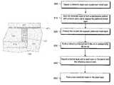
- FIG. 3is an illustration of a top view of a trench and an opening filled with refractory interconnect over an underlying metal layer.
- FIG. 4is a cross-sectional view of FIG. 3 through line A-A illustrating the opening filled with refractory interconnect.
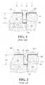
- FIG. 5illustrates the device in FIG. 4 after depositing a barrier layer, a seed layer and a conductive layer in a trench adjacent to and on the refractory interconnect.
- FIG. 7illustrates a system with a central processing unit comprising dual metal interconnects.
- FIG. 3is an illustration of a top view of the trench 120 and the opening 110 in the dielectric region 180 filled with a refractory interconnect 310 over the underlying metal 170 , which is part of a patterned metal layer, in accordance with one embodiment of the invention.
- the refractory interconnect 310may be a contact, a line, a via, or another conducting element with an opening width 112 substantially equal to or larger than 50 nm, where the opening width 112 is a nominal width of the opening 110 .
- the trench 120may be shaped in a block pattern, a v-shaped pattern, a semi-circular pattern, and/or an irregular pattern etched or otherwise formed in the dielectric region 180 .
- the dielectric region 180may be formed using silicon oxide, lightly doped silicon oxide, a fluoropolymer, a porous silicon oxide, silicon oxynitride, and/or silicon nitride.
- the trench 120is positioned directly above the refractory interconnect 310 .
- the trench 120may be positioned on a side of the refractory interconnect 310 (not shown) and directly adjacent to the refractory interconnect 310 to provide an exposed surface of the refractory interconnect 310 .
- the trench 120may be pretreated using argon (Ar) ion bombardment or a plasma process formed using a mixture of hydrogen (H 2 ) and helium (He), and/or a mixture of H 2 and Ar.
- Pretreatment of the trench 120is performed, in one example, to reduce an oxide layer on exposed metal surfaces to promote catalytic behavior.
- the pretreatment processmay be performed in a plasma chamber at a temperature ranging substantially between 100 to 200 degrees Celsius (° C.) and preferably about 150 (° C.).
- the plasma processmay be applied substantially between 20 to 60 seconds using an applied power substantially between 200-1000 Watts.
- the refractory interconnect 310may be formed in the opening 110 using a selective deposition process that substantially fills high aspect ratio features, particularly at or above 3:1, originating from the bottom of the feature to avoid creation of voids, seams, and/or other defects in the opening 110 .
- the refractory interconnect 310may be deposited in whole or at least in part by using an electroless deposition process that operates, for example, from a spontaneous reduction of a metal from a solution of its salt with a reducing agent or similar source of electrons in the presence of a catalyst or catalyst surface such as the underlying metal surface 160 .
- the refractory interconnect 310is a metal that is selectively designed to diffuse slowly through the dielectric region 180 while providing electromigration resistance.
- the refractory interconnect 310without deposition of an intervening barrier 130 between the dielectric region 180 and the refractory interconnect 310 , which would otherwise consume a portion of the opening 110 while increasing process complexity and manufacturing cost, reduces resistance to electrical flow between the refractory interconnect 310 and an underlying metal 170 .
- the refractory interconnect 310may be formed directly on or adjacent to the underlying metal 170 and one or more walls or sides of the opening 110 without first forming a barrier 130 .
- the trench 120is formed using an etch process or another erosion process used to remove a portion of the dielectric region 180 .
- the refractory interconnect 310is formed from the bottom up. In another embodiment, the refractory interconnect 310 , particularly in alloy form may be doped with, or contain small amounts of boron and/or phosphorus to impart amorphous properties.
- the trench interconnect 420comprising a seed layer and an interconnect layer, or conductor may be formed of the same material or from different materials.
- the trench interconnect 420may be formed using one or more low resistivity metals such as silver (Ag), copper (Cu), aluminum (Al), and their alloys.
- the refractory interconnect 310 and the trench interconnect 420are formed of two different materials, referred to here as a dual metal interconnect.
- the trench interconnect 420is separated from the underlying metal 170 by the dielectric region 180 with a thickness roughly equivalent to the opening height 114 . While the opening width 112 continues to shrink to allow greater device density, the opening height 114 remains relatively thick in comparison. Embodiments of the invention allow for progressively higher aspect ratio openings, or the ratio of the opening height 114 to the opening width 112 , that would have otherwise been prohibited due to gap-fill constraints, thereby reducing capacitance and making the microelectronic device more power efficient.
- FIG. 6illustrates a cross-sectional view of a dual metal interconnect in a microelectronic device 600 , such as a central processing unit or a memory unit, in accordance with one embodiment.
- the microelectronic device 600contains a substrate 605 that may comprise silicon, gallium arsenide (GaAs), or indium antimonide (InSb) in monocrystalline form.
- the substrate 605may further comprise buried layers such as one or more silicon-on-insulator layers.
- One or more front end filmsare formed on the substrate 605 to form a pre-metal dielectric 610 .
- the pre-metal dielectric 610may comprise one or more films typically used in contemporary device fabrication known to one skilled in the art, such as silicon oxide, silicon nitride, doped or un-doped polysilicon, lanthanum oxide, tantalum oxide, titanium oxide, hafnium oxide, zirconium oxide, lead-zirconate-titanate (PZT), barium-strontium-titanate (BST), or aluminum oxide.
- the pre-metal dielectric layer 610may be deposited using methods such as thermal deposition, plasma enhanced chemical vapor deposition (PECVD), high density chemical vapor deposition (HDCVD), and/or sputtering.
- a series of interlayer dielectric layers 620comprising refractory interconnects 410 , a trench barrier 420 , and a trench conductor 430 are formed over the pre-metal dielectric layer 610 .
- the interlayer dielectric layers 620may comprise a silicon oxide, silicon nitride, or a low k dielectric (e.g., k ⁇ 3) such as carbon-doped oxide (CDO).
- CDOcarbon-doped oxide
- the interlayer dielectric layers 620may be planarized, or polished using a process such as chemical mechanical planarization (CMP). The planarization process erodes a top portion of the dielectric material to create a uniform surface while improving the optical resolution of subsequent lithography steps.
- CMPchemical mechanical planarization
- the refractory interconnects 310are filled with one or more refractory metals such as cobalt (Co), nickel (Ni), palladium (Pd), platinum (Pt), tungsten (W), ruthenium (Ru), and their alloys while the trench interconnects 420 and underlying metals 170 are formed by a damascene or dual-damascene process with copper or a copper alloy using an electroplating process to fill recesses such as trenches 120 in the interlayer dielectric layers 620 .
- the trench interconnects 420 and the interlayer dielectric layers 620may be planarized using a CMP process or another planarizing process known to one skilled in the art.
- FIG. 7illustrates a communications system 700 with a central processing unit (CPU) 710 comprising dual metal interconnects in accordance with one embodiment.
- the communications system 700may include a motherboard 720 with the CPU 710 , and a networking interface 730 coupled to a bus 740 . More specifically, the CPU 710 may comprise the earlier described dual metal interconnect structure and/or its method of fabrication.
- the communications system 700may additionally include other components described herein, including but are not limited to volatile and non-volatile memory, a graphics processor, a digital signal processor, a crypto processor, a chipset, mass storage (such as hard disk, compact disk (CD), digital versatile disk (DVD)), and so forth.
- FIG. 8is a flowchart describing one embodiment of a fabrication process used to form dual metal interconnect structures.
- a dielectric layeris deposited over a patterned metal layer.
- the dielectric layeris etched to form a damascene pattern with a trench and an opening to expose the patterned metal layer. The opening is pretreated and the patterned metal layer is exposed in element 820 .
- a refractory interconnect 310is formed in the opening to substantially fill the opening.
- a barrier layer 410is deposited and a seed layer is formed on the trench and the refractory interconnect 310 in element 840 .
- a low resistivity metalis formed on the seed layer in element 850 to form a trench interconnect 420 .
- the process described in FIG. 8may be repeated one or more times to provide a plurality of additional conductors.
Landscapes
- Engineering & Computer Science (AREA)
- Physics & Mathematics (AREA)
- Condensed Matter Physics & Semiconductors (AREA)
- General Physics & Mathematics (AREA)
- Computer Hardware Design (AREA)
- Microelectronics & Electronic Packaging (AREA)
- Power Engineering (AREA)
- Manufacturing & Machinery (AREA)
- Internal Circuitry In Semiconductor Integrated Circuit Devices (AREA)
Abstract
Description
Claims (14)
Priority Applications (7)
| Application Number | Priority Date | Filing Date | Title |
|---|---|---|---|
| US12/316,304US7867891B2 (en) | 2008-12-10 | 2008-12-10 | Dual metal interconnects for improved gap-fill, reliability, and reduced capacitance |
| EP09832386.8AEP2356674B1 (en) | 2008-12-10 | 2009-12-01 | Dual metal interconnects |
| JP2011531271AJP2012505554A (en) | 2008-12-10 | 2009-12-01 | Dual metal interconnect to improve gap fill reliability and reduce capacity |
| PCT/US2009/066198WO2010068523A2 (en) | 2008-12-10 | 2009-12-01 | Dual metal interconnects for improved gap-fill, reliability, and reduced capacitance |
| KR1020117007716AKR101238953B1 (en) | 2008-12-10 | 2009-12-01 | Dual metal interconnects for improved gap-fill, reliability, and reduced capacitance |
| CN2009801399711ACN102171797A (en) | 2008-12-10 | 2009-12-01 | Dual metal interconnects for improved gap-fill, reliability, and reduced capacitance |
| US12/967,865US20110079910A1 (en) | 2008-12-10 | 2010-12-14 | Dual metal interconnects for improved gap-fill, reliability, and reduced capacitance |
Applications Claiming Priority (1)
| Application Number | Priority Date | Filing Date | Title |
|---|---|---|---|
| US12/316,304US7867891B2 (en) | 2008-12-10 | 2008-12-10 | Dual metal interconnects for improved gap-fill, reliability, and reduced capacitance |
Related Child Applications (1)
| Application Number | Title | Priority Date | Filing Date |
|---|---|---|---|
| US12/967,865DivisionUS20110079910A1 (en) | 2008-12-10 | 2010-12-14 | Dual metal interconnects for improved gap-fill, reliability, and reduced capacitance |
Publications (2)
| Publication Number | Publication Date |
|---|---|
| US20100140804A1 US20100140804A1 (en) | 2010-06-10 |
| US7867891B2true US7867891B2 (en) | 2011-01-11 |
Family
ID=42230178
Family Applications (2)
| Application Number | Title | Priority Date | Filing Date |
|---|---|---|---|
| US12/316,304ActiveUS7867891B2 (en) | 2008-12-10 | 2008-12-10 | Dual metal interconnects for improved gap-fill, reliability, and reduced capacitance |
| US12/967,865AbandonedUS20110079910A1 (en) | 2008-12-10 | 2010-12-14 | Dual metal interconnects for improved gap-fill, reliability, and reduced capacitance |
Family Applications After (1)
| Application Number | Title | Priority Date | Filing Date |
|---|---|---|---|
| US12/967,865AbandonedUS20110079910A1 (en) | 2008-12-10 | 2010-12-14 | Dual metal interconnects for improved gap-fill, reliability, and reduced capacitance |
Country Status (6)
| Country | Link |
|---|---|
| US (2) | US7867891B2 (en) |
| EP (1) | EP2356674B1 (en) |
| JP (1) | JP2012505554A (en) |
| KR (1) | KR101238953B1 (en) |
| CN (1) | CN102171797A (en) |
| WO (1) | WO2010068523A2 (en) |
Cited By (12)
| Publication number | Priority date | Publication date | Assignee | Title |
|---|---|---|---|---|
| US8508018B2 (en) | 2010-09-24 | 2013-08-13 | Intel Corporation | Barrier layers |
| US8779589B2 (en) | 2010-12-20 | 2014-07-15 | Intel Corporation | Liner layers for metal interconnects |
| US9128289B2 (en) | 2012-12-28 | 2015-09-08 | Pixtronix, Inc. | Display apparatus incorporating high-aspect ratio electrical interconnects |
| US20160163587A1 (en)* | 2014-12-08 | 2016-06-09 | International Business Machines Corporation | Self-aligned via interconnect structures |
| US9514983B2 (en) | 2012-12-28 | 2016-12-06 | Intel Corporation | Cobalt based interconnects and methods of fabrication thereof |
| US9583386B2 (en) | 2014-10-25 | 2017-02-28 | Lam Research Corporation | Interlevel conductor pre-fill utilizing selective barrier deposition |
| US9704798B2 (en) | 2013-12-20 | 2017-07-11 | Intel Corporation | Using materials with different etch rates to fill trenches in semiconductor devices |
| US9997457B2 (en) | 2013-12-20 | 2018-06-12 | Intel Corporation | Cobalt based interconnects and methods of fabrication thereof |
| US10431544B2 (en) | 2016-02-17 | 2019-10-01 | International Business Machines Corporation | Self-forming barrier for cobalt interconnects |
| US11075165B2 (en) | 2019-07-19 | 2021-07-27 | Applied Materials, Inc. | Methods and apparatus for forming dual metal interconnects |
| US11107727B2 (en) | 2019-05-10 | 2021-08-31 | International Business Machines Corporation | Double metal double patterning with vias extending into dielectric |
| US11177214B2 (en) | 2020-01-15 | 2021-11-16 | International Business Machines Corporation | Interconnects with hybrid metal conductors |
Families Citing this family (5)
| Publication number | Priority date | Publication date | Assignee | Title |
|---|---|---|---|---|
| US20120153483A1 (en)* | 2010-12-20 | 2012-06-21 | Akolkar Rohan N | Barrierless single-phase interconnect |
| KR20130000218A (en)* | 2011-06-22 | 2013-01-02 | 삼성디스플레이 주식회사 | Electrode including magnetic material and organic light emitting device using the electrode |
| WO2017087005A1 (en)* | 2015-11-21 | 2017-05-26 | Intel Corporation | Metallization stacks with enclosed vias |
| TW201840903A (en)* | 2016-11-20 | 2018-11-16 | 美商應用材料股份有限公司 | Methods to selectively deposit corrosion-free metal contacts |
| US10395986B1 (en) | 2018-05-30 | 2019-08-27 | International Business Machines Corporation | Fully aligned via employing selective metal deposition |
Citations (9)
| Publication number | Priority date | Publication date | Assignee | Title |
|---|---|---|---|---|
| US4692349A (en)* | 1986-03-03 | 1987-09-08 | American Telephone And Telegraph Company, At&T Bell Laboratories | Selective electroless plating of vias in VLSI devices |
| US6030877A (en)* | 1997-10-06 | 2000-02-29 | Industrial Technology Research Institute | Electroless gold plating method for forming inductor structures |
| US6197685B1 (en)* | 1997-07-11 | 2001-03-06 | Matsushita Electronics Corporation | Method of producing multilayer wiring device with offset axises of upper and lower plugs |
| US20040087117A1 (en) | 2002-08-23 | 2004-05-06 | Amberwave Systems Corporation | Semiconductor heterostructures and related methods |
| US20060113542A1 (en) | 2004-11-30 | 2006-06-01 | Massachusetts Institute Of Technology | Method for forming low defect density alloy graded layers and structure containing such layers |
| US20070235802A1 (en) | 2006-04-05 | 2007-10-11 | Chartered Semiconductor Manufacturing Ltd | Method to control source/drain stressor profiles for stress engineering |
| US20080122101A1 (en)* | 2004-09-02 | 2008-05-29 | Rohm Co., Ltd. | Manufacturing Method Of Semiconductor Device And Semiconductor Device Produced Therewith |
| US7432200B2 (en) | 2005-12-15 | 2008-10-07 | Intel Corporation | Filling narrow and high aspect ratio openings using electroless deposition |
| WO2010068530A2 (en) | 2008-12-11 | 2010-06-17 | Intel Corporation | Graded high germanium compound films for strained semiconductor devices |
Family Cites Families (23)
| Publication number | Priority date | Publication date | Assignee | Title |
|---|---|---|---|---|
| US4957775A (en)* | 1986-05-29 | 1990-09-18 | Massachusetts Institute Of Technology | Method and apparatus for refractory metal deposition |
| JPH04307736A (en)* | 1991-04-04 | 1992-10-29 | Canon Inc | Interconnection method of fine multilayer-structure semiconductor element |
| JPH06104207A (en)* | 1992-09-18 | 1994-04-15 | Toshiba Corp | Method for manufacturing semiconductor device |
| JPH07135209A (en)* | 1993-11-09 | 1995-05-23 | Matsushita Electric Ind Co Ltd | Multilayer wiring structure and manufacturing method thereof |
| JP3605291B2 (en)* | 1997-08-29 | 2004-12-22 | 株式会社日立製作所 | Semiconductor integrated circuit device |
| JP2001135638A (en)* | 1999-11-04 | 2001-05-18 | Sony Corp | Semiconductor device and its manufacturing method |
| US6495019B1 (en)* | 2000-04-19 | 2002-12-17 | Agere Systems Inc. | Device comprising micromagnetic components for power applications and process for forming device |
| US6368910B1 (en)* | 2000-11-24 | 2002-04-09 | Winbond Electronics Corp. | Method of fabricating ruthenium-based contact plug for memory devices |
| JP4198906B2 (en)* | 2001-11-15 | 2008-12-17 | 株式会社ルネサステクノロジ | Semiconductor device and manufacturing method of semiconductor device |
| JP2003179057A (en)* | 2001-12-12 | 2003-06-27 | Sony Corp | Semiconductor device and method of manufacturing the same |
| US7008872B2 (en)* | 2002-05-03 | 2006-03-07 | Intel Corporation | Use of conductive electrolessly deposited etch stop layers, liner layers and via plugs in interconnect structures |
| JP2004289046A (en)* | 2003-03-25 | 2004-10-14 | Renesas Technology Corp | Method for manufacturing semiconductor device having capacitor |
| JP2007502551A (en)* | 2003-06-13 | 2007-02-08 | アプライド マテリアルズ インコーポレイテッド | Integration of ALD tantalum nitride for copper metallization |
| US7304388B2 (en) | 2003-06-26 | 2007-12-04 | Intel Corporation | Method and apparatus for an improved air gap interconnect structure |
| US7345350B2 (en)* | 2003-09-23 | 2008-03-18 | Micron Technology, Inc. | Process and integration scheme for fabricating conductive components, through-vias and semiconductor components including conductive through-wafer vias |
| KR100621630B1 (en)* | 2004-08-25 | 2006-09-19 | 삼성전자주식회사 | Damascene process using dissimilar metals |
| CN100472739C (en)* | 2004-11-08 | 2009-03-25 | Tel艾派恩有限公司 | Copper interconnect wiring and method of forming thereof |
| JP2006216690A (en)* | 2005-02-02 | 2006-08-17 | Renesas Technology Corp | Semiconductor device |
| KR100703973B1 (en)* | 2005-07-20 | 2007-04-06 | 삼성전자주식회사 | Wiring of a semiconductor device having a double capping film and a method of forming the same |
| US20070099806A1 (en)* | 2005-10-28 | 2007-05-03 | Stewart Michael P | Composition and method for selectively removing native oxide from silicon-containing surfaces |
| KR100894769B1 (en)* | 2006-09-29 | 2009-04-24 | 주식회사 하이닉스반도체 | Metal wiring formation method of semiconductor device |
| JP2007005840A (en)* | 2006-10-16 | 2007-01-11 | Renesas Technology Corp | Method of manufacturing semiconductor integrated circuit device |
| JP4921945B2 (en)* | 2006-12-13 | 2012-04-25 | 株式会社東芝 | Semiconductor device manufacturing method and semiconductor device |
- 2008
- 2008-12-10USUS12/316,304patent/US7867891B2/enactiveActive
- 2009
- 2009-12-01KRKR1020117007716Apatent/KR101238953B1/enactiveActive
- 2009-12-01JPJP2011531271Apatent/JP2012505554A/enactivePending
- 2009-12-01CNCN2009801399711Apatent/CN102171797A/enactivePending
- 2009-12-01WOPCT/US2009/066198patent/WO2010068523A2/enactiveApplication Filing
- 2009-12-01EPEP09832386.8Apatent/EP2356674B1/enactiveActive
- 2010
- 2010-12-14USUS12/967,865patent/US20110079910A1/ennot_activeAbandoned
Patent Citations (9)
| Publication number | Priority date | Publication date | Assignee | Title |
|---|---|---|---|---|
| US4692349A (en)* | 1986-03-03 | 1987-09-08 | American Telephone And Telegraph Company, At&T Bell Laboratories | Selective electroless plating of vias in VLSI devices |
| US6197685B1 (en)* | 1997-07-11 | 2001-03-06 | Matsushita Electronics Corporation | Method of producing multilayer wiring device with offset axises of upper and lower plugs |
| US6030877A (en)* | 1997-10-06 | 2000-02-29 | Industrial Technology Research Institute | Electroless gold plating method for forming inductor structures |
| US20040087117A1 (en) | 2002-08-23 | 2004-05-06 | Amberwave Systems Corporation | Semiconductor heterostructures and related methods |
| US20080122101A1 (en)* | 2004-09-02 | 2008-05-29 | Rohm Co., Ltd. | Manufacturing Method Of Semiconductor Device And Semiconductor Device Produced Therewith |
| US20060113542A1 (en) | 2004-11-30 | 2006-06-01 | Massachusetts Institute Of Technology | Method for forming low defect density alloy graded layers and structure containing such layers |
| US7432200B2 (en) | 2005-12-15 | 2008-10-07 | Intel Corporation | Filling narrow and high aspect ratio openings using electroless deposition |
| US20070235802A1 (en) | 2006-04-05 | 2007-10-11 | Chartered Semiconductor Manufacturing Ltd | Method to control source/drain stressor profiles for stress engineering |
| WO2010068530A2 (en) | 2008-12-11 | 2010-06-17 | Intel Corporation | Graded high germanium compound films for strained semiconductor devices |
Non-Patent Citations (1)
| Title |
|---|
| International Search Report/Witten Opinion for Patent Application No. PCT/US2009/066334, mailed Jun. 22, 2010, 11 pages. |
Cited By (21)
| Publication number | Priority date | Publication date | Assignee | Title |
|---|---|---|---|---|
| US8508018B2 (en) | 2010-09-24 | 2013-08-13 | Intel Corporation | Barrier layers |
| US8779589B2 (en) | 2010-12-20 | 2014-07-15 | Intel Corporation | Liner layers for metal interconnects |
| US9514983B2 (en) | 2012-12-28 | 2016-12-06 | Intel Corporation | Cobalt based interconnects and methods of fabrication thereof |
| US9128289B2 (en) | 2012-12-28 | 2015-09-08 | Pixtronix, Inc. | Display apparatus incorporating high-aspect ratio electrical interconnects |
| US12354956B2 (en) | 2013-12-20 | 2025-07-08 | Tahoe Research, Ltd. | Cobalt based interconnects and methods of fabrication thereof |
| US9704798B2 (en) | 2013-12-20 | 2017-07-11 | Intel Corporation | Using materials with different etch rates to fill trenches in semiconductor devices |
| US9997457B2 (en) | 2013-12-20 | 2018-06-12 | Intel Corporation | Cobalt based interconnects and methods of fabrication thereof |
| US11328993B2 (en) | 2013-12-20 | 2022-05-10 | Intel Corporation | Cobalt based interconnects and methods of fabrication thereof |
| US10700007B2 (en) | 2013-12-20 | 2020-06-30 | Intel Corporation | Cobalt based interconnects and methods of fabrication thereof |
| US11862563B2 (en) | 2013-12-20 | 2024-01-02 | Tahoe Research, Ltd. | Cobalt based interconnects and methods of fabrication thereof |
| US9583386B2 (en) | 2014-10-25 | 2017-02-28 | Lam Research Corporation | Interlevel conductor pre-fill utilizing selective barrier deposition |
| US10395984B2 (en) | 2014-12-08 | 2019-08-27 | International Business Machines Corporation | Self-aligned via interconnect structures |
| US20160163587A1 (en)* | 2014-12-08 | 2016-06-09 | International Business Machines Corporation | Self-aligned via interconnect structures |
| US10727122B2 (en)* | 2014-12-08 | 2020-07-28 | International Business Machines Corporation | Self-aligned via interconnect structures |
| US11348832B2 (en) | 2014-12-08 | 2022-05-31 | International Business Machines Corporation | Self-aligned via interconnect structures |
| US10446496B2 (en) | 2016-02-17 | 2019-10-15 | International Business Machines Corporation | Self-forming barrier for cobalt interconnects |
| US10431544B2 (en) | 2016-02-17 | 2019-10-01 | International Business Machines Corporation | Self-forming barrier for cobalt interconnects |
| US11107727B2 (en) | 2019-05-10 | 2021-08-31 | International Business Machines Corporation | Double metal double patterning with vias extending into dielectric |
| US11075165B2 (en) | 2019-07-19 | 2021-07-27 | Applied Materials, Inc. | Methods and apparatus for forming dual metal interconnects |
| US11948885B2 (en) | 2019-07-19 | 2024-04-02 | Applied Materials, Inc. | Methods and apparatus for forming dual metal interconnects |
| US11177214B2 (en) | 2020-01-15 | 2021-11-16 | International Business Machines Corporation | Interconnects with hybrid metal conductors |
Also Published As
| Publication number | Publication date |
|---|---|
| EP2356674B1 (en) | 2023-10-11 |
| CN102171797A (en) | 2011-08-31 |
| WO2010068523A3 (en) | 2010-08-26 |
| EP2356674A2 (en) | 2011-08-17 |
| JP2012505554A (en) | 2012-03-01 |
| WO2010068523A2 (en) | 2010-06-17 |
| EP2356674A4 (en) | 2017-12-06 |
| KR20110059752A (en) | 2011-06-03 |
| KR101238953B1 (en) | 2013-03-04 |
| US20100140804A1 (en) | 2010-06-10 |
| US20110079910A1 (en) | 2011-04-07 |
Similar Documents
| Publication | Publication Date | Title |
|---|---|---|
| US7867891B2 (en) | Dual metal interconnects for improved gap-fill, reliability, and reduced capacitance | |
| US10804147B2 (en) | Semiconductor device with reduced via resistance | |
| US7915162B2 (en) | Method of forming damascene filament wires | |
| US6821879B2 (en) | Copper interconnect by immersion/electroless plating in dual damascene process | |
| US6509267B1 (en) | Method of forming low resistance barrier on low k interconnect with electrolessly plated copper seed layer | |
| US9293412B2 (en) | Graphene and metal interconnects with reduced contact resistance | |
| US10903116B2 (en) | Void-free metallic interconnect structures with self-formed diffusion barrier layers | |
| US20040219783A1 (en) | Copper dual damascene interconnect technology | |
| US12218003B2 (en) | Selective ILD deposition for fully aligned via with airgap | |
| US20020167089A1 (en) | Copper dual damascene interconnect technology | |
| US6555461B1 (en) | Method of forming low resistance barrier on low k interconnect | |
| JP2009026989A (en) | Semiconductor device and manufacturing method of semiconductor device | |
| KR20040001989A (en) | Method for forming a copper metal line in semiconductor device | |
| US7638423B2 (en) | Semiconductor device and method of forming wires of semiconductor device | |
| KR100924556B1 (en) | Metal wiring of semiconductor device and method of forming the same | |
| US20230077760A1 (en) | Top via interconnects without barrier metal between via and above line |
Legal Events
| Date | Code | Title | Description |
|---|---|---|---|
| AS | Assignment | Owner name:INTEL CORPORATION,CALIFORNIA Free format text:ASSIGNMENT OF ASSIGNORS INTEREST;ASSIGNORS:BRIEN, KEVIN O';AKOLKAR, ROHAN;INDUKURI, TEJASWI;AND OTHERS;REEL/FRAME:022210/0406 Effective date:20081126 Owner name:INTEL CORPORATION, CALIFORNIA Free format text:ASSIGNMENT OF ASSIGNORS INTEREST;ASSIGNORS:BRIEN, KEVIN O';AKOLKAR, ROHAN;INDUKURI, TEJASWI;AND OTHERS;REEL/FRAME:022210/0406 Effective date:20081126 | |
| STCF | Information on status: patent grant | Free format text:PATENTED CASE | |
| FPAY | Fee payment | Year of fee payment:4 | |
| MAFP | Maintenance fee payment | Free format text:PAYMENT OF MAINTENANCE FEE, 8TH YEAR, LARGE ENTITY (ORIGINAL EVENT CODE: M1552) Year of fee payment:8 | |
| AS | Assignment | Owner name:TAHOE RESEARCH, LTD., IRELAND Free format text:ASSIGNMENT OF ASSIGNORS INTEREST;ASSIGNOR:INTEL CORPORATION;REEL/FRAME:061175/0176 Effective date:20220718 | |
| FEPP | Fee payment procedure | Free format text:MAINTENANCE FEE REMINDER MAILED (ORIGINAL EVENT CODE: REM.); ENTITY STATUS OF PATENT OWNER: LARGE ENTITY | |
| FEPP | Fee payment procedure | Free format text:11.5 YR SURCHARGE- LATE PMT W/IN 6 MO, LARGE ENTITY (ORIGINAL EVENT CODE: M1556); ENTITY STATUS OF PATENT OWNER: LARGE ENTITY | |
| MAFP | Maintenance fee payment | Free format text:PAYMENT OF MAINTENANCE FEE, 12TH YEAR, LARGE ENTITY (ORIGINAL EVENT CODE: M1553); ENTITY STATUS OF PATENT OWNER: LARGE ENTITY Year of fee payment:12 |