US7867850B2 - Enhanced multi-bit non-volatile memory device with resonant tunnel barrier - Google Patents
Enhanced multi-bit non-volatile memory device with resonant tunnel barrierDownload PDFInfo
- Publication number
- US7867850B2 US7867850B2US12/349,133US34913309AUS7867850B2US 7867850 B2US7867850 B2US 7867850B2US 34913309 AUS34913309 AUS 34913309AUS 7867850 B2US7867850 B2US 7867850B2
- Authority
- US
- United States
- Prior art keywords
- layer
- forming
- tunnel barrier
- resonant tunnel
- charge
- Prior art date
- Legal status (The legal status is an assumption and is not a legal conclusion. Google has not performed a legal analysis and makes no representation as to the accuracy of the status listed.)
- Active, expires
Links
- 230000004888barrier functionEffects0.000titleclaimsabstractdescription72
- 230000015654memoryEffects0.000claimsabstractdescription85
- 230000000903blocking effectEffects0.000claimsabstractdescription46
- 229910021417amorphous siliconInorganic materials0.000claimsabstractdescription12
- GNPVGFCGXDBREM-UHFFFAOYSA-Ngermanium atomChemical compound[Ge]GNPVGFCGXDBREM-UHFFFAOYSA-N0.000claimsabstractdescription12
- 229910002244LaAlO3Inorganic materials0.000claimsabstractdescription11
- 229910052732germaniumInorganic materials0.000claimsabstractdescription10
- 239000000463materialSubstances0.000claimsdescription50
- 239000000758substrateSubstances0.000claimsdescription32
- 150000004767nitridesChemical class0.000claimsdescription29
- 238000000034methodMethods0.000claimsdescription24
- 238000002161passivationMethods0.000claimsdescription16
- 229910021420polycrystalline siliconInorganic materials0.000claimsdescription7
- 229920005591polysiliconPolymers0.000claimsdescription3
- ATJFFYVFTNAWJD-UHFFFAOYSA-NTinChemical compound[Sn]ATJFFYVFTNAWJD-UHFFFAOYSA-N0.000claims2
- 238000007667floatingMethods0.000abstractdescription29
- 229910052710siliconInorganic materials0.000abstractdescription10
- 239000010703siliconSubstances0.000abstractdescription10
- VYPSYNLAJGMNEJ-UHFFFAOYSA-NSilicium dioxideChemical compoundO=[Si]=OVYPSYNLAJGMNEJ-UHFFFAOYSA-N0.000description22
- 238000010586diagramMethods0.000description19
- 229910052681coesiteInorganic materials0.000description11
- 229910052906cristobaliteInorganic materials0.000description11
- 239000000377silicon dioxideSubstances0.000description11
- 229910052682stishoviteInorganic materials0.000description11
- 229910052905tridymiteInorganic materials0.000description11
- 238000009826distributionMethods0.000description9
- 238000005516engineering processMethods0.000description9
- XUIMIQQOPSSXEZ-UHFFFAOYSA-NSiliconChemical compound[Si]XUIMIQQOPSSXEZ-UHFFFAOYSA-N0.000description8
- 229910052751metalInorganic materials0.000description8
- 239000002184metalSubstances0.000description8
- 230000006870functionEffects0.000description6
- 239000004065semiconductorSubstances0.000description6
- NRTOMJZYCJJWKI-UHFFFAOYSA-NTitanium nitrideChemical compound[Ti]#NNRTOMJZYCJJWKI-UHFFFAOYSA-N0.000description4
- 230000008901benefitEffects0.000description4
- 238000009792diffusion processMethods0.000description4
- 239000002019doping agentSubstances0.000description4
- 239000012535impuritySubstances0.000description4
- MZLGASXMSKOWSE-UHFFFAOYSA-Ntantalum nitrideChemical compound[Ta]#NMZLGASXMSKOWSE-UHFFFAOYSA-N0.000description4
- 230000005689Fowler Nordheim tunnelingEffects0.000description3
- 238000004891communicationMethods0.000description3
- 229910017817a-GeInorganic materials0.000description2
- 230000006978adaptationEffects0.000description2
- 239000004020conductorSubstances0.000description2
- 230000008878couplingEffects0.000description2
- 238000010168coupling processMethods0.000description2
- 238000005859coupling reactionMethods0.000description2
- 239000006185dispersionSubstances0.000description2
- 239000012212insulatorSubstances0.000description2
- 239000003990capacitorSubstances0.000description1
- 239000000969carrierSubstances0.000description1
- 230000001351cycling effectEffects0.000description1
- 230000014759maintenance of locationEffects0.000description1
- 230000006386memory functionEffects0.000description1
- 229920001690polydopaminePolymers0.000description1
- 230000009467reductionEffects0.000description1
- 229910052594sapphireInorganic materials0.000description1
- 239000010980sapphireSubstances0.000description1
- 239000007787solidSubstances0.000description1
- 239000010409thin filmSubstances0.000description1
- 230000005641tunnelingEffects0.000description1
Images


Classifications
- G—PHYSICS
- G11—INFORMATION STORAGE
- G11C—STATIC STORES
- G11C11/00—Digital stores characterised by the use of particular electric or magnetic storage elements; Storage elements therefor
- G11C11/56—Digital stores characterised by the use of particular electric or magnetic storage elements; Storage elements therefor using storage elements with more than two stable states represented by steps, e.g. of voltage, current, phase, frequency
- G—PHYSICS
- G11—INFORMATION STORAGE
- G11C—STATIC STORES
- G11C16/00—Erasable programmable read-only memories
- G11C16/02—Erasable programmable read-only memories electrically programmable
- G11C16/04—Erasable programmable read-only memories electrically programmable using variable threshold transistors, e.g. FAMOS
- G11C16/0466—Erasable programmable read-only memories electrically programmable using variable threshold transistors, e.g. FAMOS comprising cells with charge storage in an insulating layer, e.g. metal-nitride-oxide-silicon [MNOS], silicon-oxide-nitride-oxide-silicon [SONOS]
- H—ELECTRICITY
- H10—SEMICONDUCTOR DEVICES; ELECTRIC SOLID-STATE DEVICES NOT OTHERWISE PROVIDED FOR
- H10D—INORGANIC ELECTRIC SEMICONDUCTOR DEVICES
- H10D30/00—Field-effect transistors [FET]
- H10D30/60—Insulated-gate field-effect transistors [IGFET]
- H10D30/68—Floating-gate IGFETs
- H10D30/6891—Floating-gate IGFETs characterised by the shapes, relative sizes or dispositions of the floating gate electrode
- H—ELECTRICITY
- H10—SEMICONDUCTOR DEVICES; ELECTRIC SOLID-STATE DEVICES NOT OTHERWISE PROVIDED FOR
- H10D—INORGANIC ELECTRIC SEMICONDUCTOR DEVICES
- H10D30/00—Field-effect transistors [FET]
- H10D30/60—Insulated-gate field-effect transistors [IGFET]
- H10D30/69—IGFETs having charge trapping gate insulators, e.g. MNOS transistors
- H10D30/694—IGFETs having charge trapping gate insulators, e.g. MNOS transistors characterised by the shapes, relative sizes or dispositions of the gate electrodes
- H—ELECTRICITY
- H10—SEMICONDUCTOR DEVICES; ELECTRIC SOLID-STATE DEVICES NOT OTHERWISE PROVIDED FOR
- H10D—INORGANIC ELECTRIC SEMICONDUCTOR DEVICES
- H10D64/00—Electrodes of devices having potential barriers
- H10D64/01—Manufacture or treatment
- H10D64/031—Manufacture or treatment of data-storage electrodes
- H10D64/035—Manufacture or treatment of data-storage electrodes comprising conductor-insulator-conductor-insulator-semiconductor structures
- H—ELECTRICITY
- H10—SEMICONDUCTOR DEVICES; ELECTRIC SOLID-STATE DEVICES NOT OTHERWISE PROVIDED FOR
- H10D—INORGANIC ELECTRIC SEMICONDUCTOR DEVICES
- H10D64/00—Electrodes of devices having potential barriers
- H10D64/01—Manufacture or treatment
- H10D64/031—Manufacture or treatment of data-storage electrodes
- H10D64/037—Manufacture or treatment of data-storage electrodes comprising charge-trapping insulators
- H—ELECTRICITY
- H10—SEMICONDUCTOR DEVICES; ELECTRIC SOLID-STATE DEVICES NOT OTHERWISE PROVIDED FOR
- H10D—INORGANIC ELECTRIC SEMICONDUCTOR DEVICES
- H10D64/00—Electrodes of devices having potential barriers
- H10D64/60—Electrodes characterised by their materials
- H10D64/66—Electrodes having a conductor capacitively coupled to a semiconductor by an insulator, e.g. MIS electrodes
- H10D64/68—Electrodes having a conductor capacitively coupled to a semiconductor by an insulator, e.g. MIS electrodes characterised by the insulator, e.g. by the gate insulator
- H10D64/681—Electrodes having a conductor capacitively coupled to a semiconductor by an insulator, e.g. MIS electrodes characterised by the insulator, e.g. by the gate insulator having a compositional variation, e.g. multilayered
- H10D64/685—Electrodes having a conductor capacitively coupled to a semiconductor by an insulator, e.g. MIS electrodes characterised by the insulator, e.g. by the gate insulator having a compositional variation, e.g. multilayered being perpendicular to the channel plane
Definitions
- the present inventionrelates generally to memory devices and in particular the present invention relates to non-volatile memory devices.
- RAMrandom-access memory
- ROMread only memory
- DRAMdynamic random access memory
- Flash memoriesmay use floating gate technology or trapping technology.
- Floating gate cellsinclude source and drain regions that may be laterally spaced apart to form an intermediate channel region. The source and drain regions are formed in a common horizontal plane of a silicon substrate.
- the floating gatetypically made of doped polysilicon, is disposed over the channel region and is electrically isolated from the other cell elements by oxide.
- the non-volatile memory function for the floating gate technologyis created by the absence or presence of charge stored on the isolated floating gate.
- the floating gate cellmay be a single level cell (SLC) or a multiple level cell (MLC).
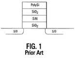
- the trapping technologyfunctions as a non-volatile memory and can be implemented in a silicon-oxide-nitride-oxide-silicon (SONOS) architecture as illustrated in FIG. 1 .
- SONOSsilicon-oxide-nitride-oxide-silicon
- the nitride trap layercan capture and store electrons or holes in order to act as a non-volatile memory.
- the cellmay be an SLC or an MLC.
- Each cell's threshold voltage (V th )determines the data that is stored in the cell. For example, in a single bit per cell, a V th of 0.5V might indicate a programmed cell while a V th of ⁇ 0.5V might indicate an erased cell.
- the multilevel cellmay have multiple V th windows that each indicate a different state. Multilevel cells take advantage of the analog nature of a traditional flash cell by assigning a bit pattern to a specific voltage range stored on the cell. This technology permits the storage of two or more bits per cell, depending on the quantity of voltage ranges assigned to the cell and the stability of the assigned voltage ranges during the lifetime operation of the memory cell.
- a cellmay be assigned four different voltage ranges of 200 mV for each range. Typically, a dead space or margin of 0.2V to 0.4V is between each range. If the voltage stored on the cell is within the first range, the cell is storing a 00. If the voltage is within the second range, the cell is storing a 01. This continues for as many ranges that are used for the cell provided these voltage ranges remain stable during the lifetime operation of the memory cell.
- MLCrequires tight control of the threshold voltage ranges and stability of these voltage ranges in order to achieve multiple memory states and associated ranges of threshold levels per cell.
- the spread in the threshold level (when programmed by a defined set of conditions) of the memory stateis affected by several factors.
- the key factorsare: (a) the statistical variations of tunnel oxide thickness and cell coupling coefficient from cell-to-cell; (b) the variation of the trapped charge centroid in density and depth; (c) cell-to-cell variation in trapped charge losses during stand-by (retention), during reading (read disturb), during partial programming (inhibit) and; (d) cell-to-cell variation in endurance (write/erase cycling) characteristics. Additionally, variations in capacitance coupling between adjacent cells creates variation in program disturb differently from cell-to-cell and contribute to the threshold spread.
- One way to reduce the threshold voltage dispersionis to use a resonant tunnel barrier transistor as illustrated in FIG. 2 .
- a resonant tunnel barrier transistoras illustrated in FIG. 2 .
- Such a transistoris comprised of a normal SiN trapping layer 201 , a SiO 2 charge blocking layer 202 , and a polysilicon gate 203 .
- the tunnel dielectric 200is comprised of a layer of SiO 2 210 , a layer of amorphous silicon 211 , and another layer of SiO 2 212 . This results in an electron band energy level diagram as illustrated in FIG. 3 .
- FIG. 3shows the electron band for the tunnel dielectric 320 that is comprised of the first SiO 2 layer 307 , the amorphous silicon layer 306 , and the second SiO 2 layer 305 .
- the electron bands for the SiN trapping layer 304 , SiO 2 charge blocking layer 303 , and gate 301are also shown.
- FIG. 4illustrates a typical prior art threshold voltage distribution for a conventional SONOS-type structure.
- Each state‘00’ ‘01’ ‘10’ and ‘11’, is shown along the threshold voltage (V th ) axis.
- V ththreshold voltage
- This diagramshows that each state has a relatively large threshold window. Such a large window might result in interference from adjacent states as well as limiting the quantity of possible states.
- each distributioncan be +/ ⁇ 0.5V.
- designing such a multi-level memory systemrequires that each state be separated from the other states by a margin. However, the margin is so small that program disturb conditions may still cause the programming of an undesired state.
- FIG. 5illustrates a typical prior art resonant tunnel barrier threshold voltage distribution. This diagram shows that each threshold voltage distribution has been substantially reduced from the prior art distributions.
- FIG. 1shows a cross-sectional view of a typical prior art SONOS structure.
- FIG. 2shows a cross-sectional view of a typical prior art resonant tunnel barrier SONOSOS structure.
- FIG. 3shows a prior art electron band energy diagram in accordance with the prior art structure of FIG. 2 .
- FIG. 4shows a typical prior art threshold voltage distribution for a conventional SONOS-type structure.
- FIG. 5shows a typical prior art threshold voltage distribution in accordance with the resonant tunnel barrier structure of FIG. 2 .
- FIG. 6shows a cross-sectional view of one embodiment of a mono-level resonant tunnel barrier floating gate transistor architecture of the present invention.
- FIG. 7shows a cross-sectional view of one embodiment of a bi-level resonant tunnel barrier floating gate transistor architecture of the present invention.
- FIG. 8shows an electron band energy level diagram of the bi-level resonant tunnel barrier transistor of FIG. 7 .
- FIG. 9shows a cross-sectional view of one embodiment of a high-k resonant tunnel barrier transistor of the present invention with an embedded trap layer.
- FIG. 10shows a cross-sectional view of another embodiment of a high-k resonant barrier transistor of the present invention with an embedded trap layer.
- FIG. 11shows an electron band energy level diagram in accordance with the structure of FIG. 9 .
- FIG. 12shows an electron band energy level diagram in accordance with the structure of FIG. 10 .
- FIG. 13shows a block diagram of one embodiment of a chip architecture of a memory device and memory system of the present invention.
- FIG. 14shows a block diagram of one embodiment of a memory module of the present invention.
- SOSsilicon-on-sapphire
- SOIsilicon-on-insulator
- TFTthin film transistor
- doped and undoped semiconductorsepitaxial layers of a silicon supported by a base semiconductor structure, as well as other semiconductor structures well known to one skilled in the art.
- wafer or substratewhen reference is made to a wafer or substrate in the following description, previous process steps may have been utilized to form regions/junctions in the base semiconductor structure, and terms wafer or substrate include the underlying layers containing such regions/junctions.
- FIG. 6illustrates a cross-sectional view of one embodiment of a floating gate memory cell of the present invention using a mono-level resonant tunnel barrier 600 .
- the one transistor cellis formed on a substrate 601 that has doped source/drain areas 602 , 603 .
- the function of each active region 602 , 603depends on the direction of biasing of the cell.
- the source/drain regions 602 , 603may be n-type regions 602 , 603 doped into a p-type substrate 601 .
- the source/drain regions 602 , 603are p-type regions 602 , 603 doped into an n-type substrate 601 .
- the resonant tunnel barrier 600is formed over the substrate 601 substantially between the pair of source/drain regions 602 , 603 .
- the tunnel barrier 600is comprised of a single amorphous layer 611 of material between two dielectric layers 610 , 612 .
- the dielectric layers 610 , 612are an oxide such as SiO 2 .
- the amorphous layer 611may be a layer of silicon (a-Si). Alternate embodiments may use germanium (a-Ge) or some other amorphous material.
- Each of the layers of the resonant tunnel barrier 600may be formed to a thickness in the range of 1-3 nm.
- the above materialsmay result in a total effective oxide thickness of the barrier 600 of approximately 3.5 nm. Alternate embodiments can use other material thicknesses.
- the resonant tunnel barrier 600provides benefits as discussed subsequently as a result of the electrons or holes having a preferred resident state after crossing the barrier at a certain energy level. In other words, under certain energy conditions, the electronic carriers have a higher probability to tunnel and once they have tunneled through the barrier, they remain in a certain well defined quantum state.
- a floating gate layer 620is formed over the resonant tunnel barrier 600 .
- the floating gate layer 620in one embodiment, is silicon. Alternate embodiments can use other materials.
- the floating gate layer 620in one embodiment, is formed to a thickness in the range of 3-6 nm.
- the floating gate material 620usually consists of silicon as stated above with a dielectric constant of nearly 12.
- a charge blocking layer 621is formed over the floating gate layer 620 .
- the charge blocking layer 621prevents the leakage of the charge from the floating gate 620 to the gate 623 .
- the blocking layer 621is comprised of HfSiON or LaAlO 3 and is formed to a thickness in the range of 5-10 nm.
- the materials used in the blocking layer 621may provide an effective oxide thickness of approximately 1 nm.
- An ultra-thin layer(e.g., 1-2 nm) of conductive metal nitride 622 may be formed over the charge blocking layer 621 and is comprised of tantalum nitride (TaN), or titanium nitride (TiN), or some other metal nitride material.
- This layer 622acts as an appropriate passivation layer and diffusion barrier for undesirable impurities and dopants.
- the passivation layer 622is not required for proper operation of the memory cell of the present invention.
- the gate 623is formed over the passivation layer 622 or charge blocking layer 621 .
- the gate 623can be comprised of heavily doped polycrystalline silicon or some other conducting material.
- the entire memory cell stack illustrated in FIG. 6may have an effective oxide thickness in the range of 5-6 nm compared to a stack as illustrated in FIG. 2 having an effective oxide thickness of 10-12 nm.
- the embodiment of FIG. 6therefore, provides a memory cell with substantially reduced voltage requirements for programming.
- FIG. 7illustrates a cross-sectional view of one embodiment of a floating gate memory cell of the present invention using a bi-level resonant tunnel barrier 700 .
- the one transistor cellis formed on a substrate 701 that has doped source/drain areas 702 , 703 .
- the function of each active region 702 , 703depends on the direction of biasing of the cell.
- the source/drain regions 702 , 703may be n-type regions 702 , 703 doped into a p-type substrate 701 .
- the source/drain regions 702 , 703are p-type regions 702 , 703 doped into an n-type substrate 701 .
- the bi-level resonant tunnel barrier 700is formed over the channel region of the substrate 701 substantially between the pair of source/drain regions 702 , 703 .
- the tunnel barrier 700is comprised of a single amorphous silicon layer 711 over a single amorphous germanium layer 712 between two dielectric layers 710 , 713 .
- An alternate embodimentforms the amorphous germanium layer over the amorphous silicon layer.
- the dielectric layers 710 , 713are an oxide such as SiO 2 .
- Each of the layers of the resonant tunnel barrier 700may be formed to a thickness in the range of 1-3 nm.
- the materialsresult in a total effective oxide thickness of the barrier 700 of approximately 3.5 nm. Alternate embodiments can use other material thicknesses.
- a floating gate layer 720is formed over the resonant tunnel barrier 700 .
- the floating gate layer 720in one embodiment, is silicon. Alternate embodiments can use other materials.
- the floating gate layer 720in one embodiment, is formed to a thickness in the range of 3-6 nm.
- the floating gate material 720usually consists of silicon as stated above with a dielectric constant of approximately 12.
- a charge blocking layer 721is formed over the floating gate layer 720 .
- the charge blocking layer 721prevents the leakage of the charge from the floating gate 720 to the gate 723 .
- the blocking layer 721is comprised of HfSiON or LaAlO 3 and is formed to a thickness in the range of 5-10 nm.
- the materials used in the blocking layer 721may provide an effective oxide thickness of approximately 1 nm.
- An ultra-thin layer (e.g., 1-2 nm) of conductive metal nitride 722may be formed over the charge blocking layer 621 and is comprised of tantalum nitride (TaN), titanium nitride (TiN), or some other metal nitride material.
- This layer 722acts as an appropriate passivation layer and diffusion barrier for undesirable impurities and dopants.
- the passivation layer 722is not required for proper operation of the memory cell of the present invention.
- the gate 723is formed over the passivation layer 722 or charge blocking layer 721 .
- the gate 723can be comprised of heavily doped polycrystalline silicon or some other conducting material.
- the entire memory cell stack illustrated in FIG. 7may have an effective oxide thickness again in the range of 5-6 nm. Similar to the illustration of FIG. 6 , this one also provides a floating gate memory cell with substantially reduced voltage requirements for programming by nearly a factor of 2.
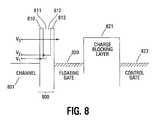
- FIG. 8illustrates an electron band energy level diagram of the bi-level resonant tunnel barrier memory cell of FIG. 7 .
- This diagramshows the tunnel barrier 800 energy levels for the first oxide layer 810 , the amorphous silicon layer 811 , the amorphous germanium layer 812 , and the second oxide layer 813 . These levels are shown in relation to the channel 801 , floating gate 820 , charge blocking layer 821 , and control gate 823 levels.
- the resonant tunnel barrier statesare illustrated as v 1 and v 2 .
- the standard Fowler-Nordheim tunneling stateis illustrated as v 3 . This diagram shows the reduced energy and, therefore, the reduced programming voltages necessary, to tunnel through the resonant tunnel barrier.
- FIG. 9illustrates a cross-sectional view of one embodiment of an embedded trap memory cell of the present invention using a mono-level resonant tunnel barrier 900 .
- the one transistor cellis formed on a substrate 901 that has doped source/drain areas 902 , 903 .
- the function of each active region 902 , 903depends on the direction of biasing of the cell.
- the source/drain regions 902 , 903may be n-type regions 902 , 903 doped into a p-type substrate 901 .
- the source/drain regions 902 , 903are p-type regions 902 , 903 doped into an n-type substrate 901 .
- the resonant tunnel barrier 900is formed over the channel region of the substrate 901 substantially between the pair of source/drain regions 902 , 903 .
- the tunnel barrier 900is comprised of a single amorphous silicon layer 911 between two dielectric layers 910 , 912 .
- the dielectric layers 910 , 913are an oxide such as SiO 2 .
- Each of the layers of the resonant tunnel barrier 900may be formed to a thickness in the range of 1-3 nm.
- the materialsresult in a total effective oxide thickness of the barrier 900 of approximately 3.5 nm. Alternate embodiments can use other material thicknesses.
- a charge trapping layer 920is formed over the resonant tunnel barrier 900 .
- the trap layer 920in one embodiment, is nitride. Alternate embodiments can use other high-k materials.
- the trapping layer 920in one embodiment, is formed to a thickness in the range of 3-6 nm.
- the choice of charge trapping materialyields an effective oxide thickness of approximately 2.5 nm. Alternate embodiments can use other thicknesses and materials that result in alternate effective oxide thicknesses.
- a high-k charge blocking layer 921is formed over the trap layer 920 .
- the charge blocking layer 921prevents the leakage of the charge from the floating gate 920 to the gate 923 .
- the blocking layer 921is comprised of HfSiON or LaAlO 3 and is formed to a thickness in the range of 5-10 nm.
- the materials used in the blocking layer 921may provide an effective oxide thickness of approximately 1-2 nm.
- the high-k charge blocking layer 921when comprised of the above materials, has a dielectric constant approximately in the range of 14-17.
- An ultra-thin layer(e.g., 1-2 nm) of conductive metal nitride 922 may be formed over the charge blocking layer 921 and is comprised of tantalum nitride (TaN), titanium nitride (TiN), or some other metal nitride material.
- This layer 922acts as an appropriate passivation layer and diffusion barrier for undesirable impurities and dopants.
- the passivation layer 922is not required for proper operation of the memory cell of the present invention.
- the gate 923is formed over the passivation layer 922 or charge blocking layer 921 .
- the gate 923can be comprised of polycrystalline silicon or some other material.
- the entire memory cell stack illustrated in FIG. 9may have an effective oxide thickness in the range of 7-8 nm.
- Such a thin EOTprovides a memory cell with substantially reduced voltage requirements for programming when compared to the device illustrated in the prior art of FIG. 2 .
- FIG. 10illustrates a cross-sectional view of one embodiment of the memory cell of the present invention using a resonant tunnel barrier 1000 .
- the one transistor cellis formed on a substrate 1001 that has doped source/drain areas 1002 , 1003 .
- the function of each active region 1002 , 1003depends on the direction of biasing of the cell.
- the source/drain regions 1002 , 1003may be n-type regions 1002 , 1003 doped into a p-type substrate 1001 .
- the source/drain regions 1002 , 1003are p-type regions 1002 , 1003 doped into an n-type substrate 1001 .
- the resonant tunnel barrier 1000is formed over the channel region in the substrate 1001 substantially between the pair of source/drain regions 1002 , 1003 .
- the resonant tunnel barrier 1000is comprised of an amorphous layer 1011 of material between two high-k dielectric layers 1010 , 1012 .
- the amorphous layer 1011may be a layer of silicon (a-Si). Alternate embodiments may use germanium (a-Ge) or some other amorphous material. In one embodiment, the amorphous layer 1011 is formed between high-k layers 1010 , 1012 of HfSiON or LaAlO 3 . Alternate embodiments may use other high dielectric constant materials around the amorphous layer 1011 .
- Each of the layers of the resonant tunnel barrier 1000may be formed to a thickness in the range of 1-3 nm.
- the materialsresult in a total effective oxide thickness of the barrier 1000 of approximately 1.5 nm. Alternate embodiments can use other material thicknesses.
- a high-k charge trapping layer 1020is formed over the resonant tunnel barrier 1000 .
- the high-k charge trapping layer 1020is comprised of an efficient trapping material such as SiN, AlN, or some other nitride. When comprised of AlN, the trapping layer 1020 has a dielectric constant of approximately 10.
- the charge trapping layer 1020in one embodiment, is formed to a thickness in the range of 3-6 nm.
- the choice of charge trapping materialyields an effective oxide thickness of approximately 2.0 nm. Alternate embodiments can use other thicknesses and materials that result in alternate effective oxide thicknesses.
- a charge blocking layer 1021is formed over the charge trapping layer 1020 .
- the charge blocking layer 1021prevents the leakage of the charge from the charge trapping layer 1020 to the gate 1023 .
- the blocking layer 1021is comprised of HfSiON or LaAlO 3 and is formed to a thickness in the range of 5-10 nm.
- the materials used in the blocking layer 1021may provide an effective oxide thickness of approximately 1 nm.
- the high-k charge blocking layerhas a dielectric constant of approximately 27.5.
- An ultra-thin layer(e.g., 1-2 nm) of conductive metal nitride 1022 may be formed over the charge blocking layer 112 and is comprised of tantalum nitride (TaN), titanium nitride (TiN), or some other metal nitride material.
- This layer 1022acts as an appropriate passivation layer and diffusion barrier for undesirable impurities and dopants.
- the passivation layer 1022is not required for proper operation of the memory cell of the present invention.
- the gate 1023is formed over the passivation layer 1022 or charge blocking layer 1021 .
- the gate 1023can be comprised of polycrystalline silicon or some other material.
- the entire memory cell stack illustrated in FIG. 10may have an effective oxide thickness in the range of 4-5 nm.
- This illustrationprovides a memory cell that can be programmed at a reduced voltage level of one-third (factor of 3) when compared with the device of FIG. 2 .
- FIG. 11illustrates an electron band energy level diagram for the resonant tunnel barrier transistor embodiment of FIG. 9 .
- This diagramshows the required energy levels for the tunnel barrier 1100 in relation to the trapping layer 1120 , charge blocking layer 1121 , and control gate 1123 .
- the tunnel barrier 1100is further comprised of the three layers 1110 - 1112 .
- the resonant tunnel barrier statesare illustrated as v 1 and v 2 .
- the standard Fowler-Nordheim tunneling stateis illustrated as v 3 . This diagram shows the reduced energy and, therefore, the reduced programming voltages necessary, to tunnel through the resonant tunnel barrier.
- FIG. 12illustrates an electron band energy level diagram for the resonant tunnel barrier transistor embodiment of FIG. 10 .
- This diagramshows the required energy levels for the tunnel barrier 1200 in relation to the trapping layer 1220 , charge blocking layer 1221 , and control gate 1223 .
- the tunnel barrier 1200is further comprised of the three layers 1210 - 1212 .
- the resonant tunnel barrier statesare illustrated as v 1 and v 2 .
- the standard Fowler-Nordheim tunneling stateis illustrated as v 3 .
- This diagramshows further reduction in energy levels and, therefore, the significantly reduced programming voltages necessary to tunnel through the resonant tunnel barrier for such a device.
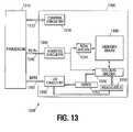
- FIG. 13illustrates a functional block diagram of a memory device 1300 and memory system 1320 of one embodiment of the present invention.
- the systemhas a processor 1310 or other controlling circuitry, for generating memory signals, that is coupled to the memory device 1300 .
- the memory device 1300has been simplified to focus on features of the memory that are helpful in understanding the present invention.
- the memory deviceincludes an array of non-volatile memory cells 1330 as discussed previously with reference to FIG. 1 .
- the memory cellsmay be flash cells or some other non-volatile memory technology.
- the memory array 1530is arranged in banks of rows and columns along word lines and bit lines, respectively.
- the arraymay be formed in a NAND architecture, a NOR architecture, or some other array architecture.
- An address buffer circuit 1340is provided to latch address signals provided on address input connections A 0 -Ax 1342 . Address signals are received and decoded by a row decoder 1344 and a column decoder 1346 to access the memory array 1330 . It will be appreciated by those skilled in the art, with the benefit of the present description, that the number of address input connections depends on the density and architecture of the memory array 1330 . That is, the number of addresses increases with both increased memory cell counts and increased bank and block counts.
- the memory device 1300reads data in the memory array 1330 by sensing voltage or current changes in the memory array columns using sense/latch circuitry 1350 .
- the sense/latch circuitryin one embodiment, is coupled to read and latch a row of data from the memory array 1330 .
- Data input and output buffer circuitry 1360is included for bi-directional data communication over a plurality of data connections 1362 with the controller 1310 .
- Write circuitry 1355is provided to write data to the memory array.
- Control circuitry 1370decodes signals provided on control connections 1372 from the processor 1310 . These signals are used to control the operations on the memory array 1330 , including data read, data write, and erase operations.
- the control circuitry 1370may be a state machine, a sequencer, or some other type of controller.
- the non-volatile memory device illustrated in FIG. 13has been simplified to facilitate a basic understanding of the features of the memory. A more detailed understanding of internal circuitry and functions of flash memories are known to those skilled in the art.
- FIG. 14is an illustration of a memory module 1400 that incorporates the memory cell embodiments as discussed previously.
- memory module 1400is illustrated as a memory card, the concepts discussed with reference to memory module 1400 are applicable to other types of removable or portable memory, e.g., USB flash drives.
- FIG. 14one example form factor is depicted in FIG. 14 , these concepts are applicable to other form factors as well.
- Memory module 1400includes a housing 1405 to enclose one or more memory devices 1410 of the present invention.
- the housing 1405includes one or more contacts 1415 for communication with a host device.
- host devicesinclude digital cameras, digital recording and playback devices, PDAs, personal computers, memory card readers, interface hubs and the like.
- the contacts 1415are in the form of a standardized interface.
- the contacts 1415might be in the form of a USB Type-A male connector.
- the contacts 1415are in the form of a semi-proprietary interface, such as might be found on COMPACTFLASH memory cards licensed by SANDISK Corporation, MEMORY STICK memory cards licensed by SONY Corporation, SD SECURE DIGITAL memory cards licensed by TOSHIBA Corporation and the like. In general, however, contacts 1415 provide an interface for passing control, address and/or data signals between the memory module 1400 and a host having compatible receptors for the contacts 1415 .
- the memory module 1400may optionally include additional circuitry 1420 .
- the additional circuitry 1420may include a memory controller for controlling access across multiple memory devices 1410 and/or for providing a translation layer between an external host and a memory device 1410 .
- a memory controllercould selectively couple an I/O connection (not shown in FIG. 14 ) of a memory device 1410 to receive the appropriate signal at the appropriate I/O connection at the appropriate time or to provide the appropriate signal at the appropriate contact 1415 at the appropriate time.
- the communication protocol between a host and the memory module 1400may be different than what is required for access of a memory device 1410 .
- a memory controllercould then translate the command sequences received from a host into the appropriate command sequences to achieve the desired access to the memory device 1410 .
- Such translationmay further include changes in signal voltage levels in addition to command sequences.
- the additional circuitry 1420may further include functionality unrelated to control of a memory device 1410 .
- the additional circuitry 1420may include circuitry to restrict read or write access to the memory module 1400 , such as password protection, biometrics or the like.
- the additional circuitry 1420may include circuitry to indicate a status of the memory module 1400 .
- the additional circuitry 1420may include functionality to determine whether power is being supplied to the memory module 1400 and whether the memory module 1400 is currently being accessed, and to display an indication of its status, such as a solid light while powered and a flashing light while being accessed.
- the additional circuitry 1420may further include passive devices, such as decoupling capacitors to help regulate power requirements within the memory module 1400 .
- the memory cells of the present inventionutilizes resonant tunnel barrier to provide tighter threshold voltage levels and greater voltage scalability.
- High dielectric constant materialsare used in the insulator stack, the charge blocking layer, and the charge trap layer in order to reduce the operating voltages of the cell.
- a deeper and more efficient trapping layer materialsimilarly reduces the required programming voltages.
Landscapes
- Engineering & Computer Science (AREA)
- Computer Hardware Design (AREA)
- Microelectronics & Electronic Packaging (AREA)
- Non-Volatile Memory (AREA)
- Semiconductor Memories (AREA)
Abstract
Description
Claims (20)
Priority Applications (1)
| Application Number | Priority Date | Filing Date | Title |
|---|---|---|---|
| US12/349,133US7867850B2 (en) | 2005-12-09 | 2009-01-06 | Enhanced multi-bit non-volatile memory device with resonant tunnel barrier |
Applications Claiming Priority (2)
| Application Number | Priority Date | Filing Date | Title |
|---|---|---|---|
| US11/298,884US7482651B2 (en) | 2005-12-09 | 2005-12-09 | Enhanced multi-bit non-volatile memory device with resonant tunnel barrier |
| US12/349,133US7867850B2 (en) | 2005-12-09 | 2009-01-06 | Enhanced multi-bit non-volatile memory device with resonant tunnel barrier |
Related Parent Applications (1)
| Application Number | Title | Priority Date | Filing Date |
|---|---|---|---|
| US11/298,884DivisionUS7482651B2 (en) | 2005-12-09 | 2005-12-09 | Enhanced multi-bit non-volatile memory device with resonant tunnel barrier |
Publications (2)
| Publication Number | Publication Date |
|---|---|
| US20090155970A1 US20090155970A1 (en) | 2009-06-18 |
| US7867850B2true US7867850B2 (en) | 2011-01-11 |
Family
ID=37890147
Family Applications (2)
| Application Number | Title | Priority Date | Filing Date |
|---|---|---|---|
| US11/298,884ActiveUS7482651B2 (en) | 2005-12-09 | 2005-12-09 | Enhanced multi-bit non-volatile memory device with resonant tunnel barrier |
| US12/349,133Active2026-01-08US7867850B2 (en) | 2005-12-09 | 2009-01-06 | Enhanced multi-bit non-volatile memory device with resonant tunnel barrier |
Family Applications Before (1)
| Application Number | Title | Priority Date | Filing Date |
|---|---|---|---|
| US11/298,884ActiveUS7482651B2 (en) | 2005-12-09 | 2005-12-09 | Enhanced multi-bit non-volatile memory device with resonant tunnel barrier |
Country Status (4)
| Country | Link |
|---|---|
| US (2) | US7482651B2 (en) |
| KR (1) | KR101056543B1 (en) |
| CN (1) | CN101356627B (en) |
| WO (1) | WO2007070424A1 (en) |
Cited By (11)
| Publication number | Priority date | Publication date | Assignee | Title |
|---|---|---|---|---|
| US9515086B2 (en) | 2014-10-24 | 2016-12-06 | Samsung Electronics Co., Ltd. | Semiconductor device, electronic device, and method of fabricating the same |
| US10153381B1 (en) | 2017-07-05 | 2018-12-11 | Micron Technology, Inc. | Memory cells having an access gate and a control gate and dielectric stacks above and below the access gate |
| US10153039B1 (en) | 2017-07-05 | 2018-12-11 | Micron Technology, Inc. | Memory cells programmed via multi-mechanism charge transports |
| US10153348B1 (en) | 2017-07-05 | 2018-12-11 | Micron Technology, Inc. | Memory configurations |
| US10176870B1 (en) | 2017-07-05 | 2019-01-08 | Micron Technology, Inc. | Multifunctional memory cells |
| US10262736B2 (en) | 2017-07-05 | 2019-04-16 | Micron Technology, Inc. | Multifunctional memory cells |
| US10276576B2 (en) | 2017-07-05 | 2019-04-30 | Micron Technology, Inc. | Gated diode memory cells |
| US10297493B2 (en) | 2017-07-05 | 2019-05-21 | Micron Technology, Inc. | Trench isolation interfaces |
| US10374101B2 (en) | 2017-07-05 | 2019-08-06 | Micron Technology, Inc. | Memory arrays |
| US10411026B2 (en) | 2017-07-05 | 2019-09-10 | Micron Technology, Inc. | Integrated computing structures formed on silicon |
| US10892340B2 (en) | 2017-07-05 | 2021-01-12 | Micron Technology, Inc. | Memory cell structures |
Families Citing this family (29)
| Publication number | Priority date | Publication date | Assignee | Title |
|---|---|---|---|---|
| EP1818989A3 (en)* | 2006-02-10 | 2010-12-01 | Semiconductor Energy Laboratory Co., Ltd. | Nonvolatile semiconductor storage device and manufacturing method thereof |
| EP1837917A1 (en)* | 2006-03-21 | 2007-09-26 | Semiconductor Energy Laboratory Co., Ltd. | Nonvolatile semiconductor memory device |
| EP1837900A3 (en)* | 2006-03-21 | 2008-10-15 | Semiconductor Energy Laboratory Co., Ltd. | Nonvolatile semiconductor memory device |
| KR101488516B1 (en)* | 2006-03-21 | 2015-02-02 | 가부시키가이샤 한도오따이 에네루기 켄큐쇼 | Nonvolatile semiconductor memory device |
| TWI416738B (en)* | 2006-03-21 | 2013-11-21 | Semiconductor Energy Lab | Nonvolatile semiconductor memory device |
| US7786526B2 (en)* | 2006-03-31 | 2010-08-31 | Semiconductor Energy Laboratory Co., Ltd. | Nonvolatile semiconductor memory device |
| US7554854B2 (en)* | 2006-03-31 | 2009-06-30 | Semiconductor Energy Laboratory Co., Ltd. | Method for deleting data from NAND type nonvolatile memory |
| EP1840947A3 (en)* | 2006-03-31 | 2008-08-13 | Semiconductor Energy Laboratory Co., Ltd. | Nonvolatile semiconductor memory device |
| US8022460B2 (en)* | 2006-03-31 | 2011-09-20 | Semiconductor Energy Laboratory Co., Ltd. | Nonvolatile semiconductor memory device |
| US7579646B2 (en)* | 2006-05-25 | 2009-08-25 | Taiwan Semiconductor Manufacturing Company, Ltd. | Flash memory with deep quantum well and high-K dielectric |
| US8816422B2 (en)* | 2006-09-15 | 2014-08-26 | Taiwan Semiconductor Manufacturing Company, Ltd. | Multi-trapping layer flash memory cell |
| US8294197B2 (en)* | 2006-09-22 | 2012-10-23 | Taiwan Semiconductor Manufacturing Company, Ltd. | Program/erase schemes for floating gate memory cells |
| JP4976796B2 (en)* | 2006-09-25 | 2012-07-18 | 株式会社東芝 | Semiconductor device |
| JP5221065B2 (en)* | 2007-06-22 | 2013-06-26 | 株式会社東芝 | Nonvolatile semiconductor memory device |
| KR20090025629A (en)* | 2007-09-06 | 2009-03-11 | 삼성전자주식회사 | Nonvolatile Memory Device and Formation Method |
| US7898850B2 (en)* | 2007-10-12 | 2011-03-01 | Micron Technology, Inc. | Memory cells, electronic systems, methods of forming memory cells, and methods of programming memory cells |
| US7759715B2 (en)* | 2007-10-15 | 2010-07-20 | Micron Technology, Inc. | Memory cell comprising dynamic random access memory (DRAM) nanoparticles and nonvolatile memory (NVM) nanoparticle |
| KR20090052682A (en)* | 2007-11-21 | 2009-05-26 | 삼성전자주식회사 | Nonvolatile Memory Devices and Cards and Systems Comprising the Same |
| JP5208537B2 (en)* | 2008-02-19 | 2013-06-12 | 株式会社東芝 | Nonvolatile memory element |
| US7875923B2 (en)* | 2008-05-15 | 2011-01-25 | Seagate Technology Llc | Band engineered high-K tunnel oxides for non-volatile memory |
| US8735963B2 (en)* | 2008-07-07 | 2014-05-27 | Taiwan Semiconductor Manufacturing Company, Ltd. | Flash memory cells having leakage-inhibition layers |
| JP2010040994A (en)* | 2008-08-08 | 2010-02-18 | Toshiba Corp | Semiconductor memory device, and method of manufacturing the same |
| US7968406B2 (en)* | 2009-01-09 | 2011-06-28 | Micron Technology, Inc. | Memory cells, methods of forming dielectric materials, and methods of forming memory cells |
| US8680629B2 (en)* | 2009-06-03 | 2014-03-25 | International Business Machines Corporation | Control of flatband voltages and threshold voltages in high-k metal gate stacks and structures for CMOS devices |
| US8274116B2 (en) | 2009-11-16 | 2012-09-25 | International Business Machines Corporation | Control of threshold voltages in high-k metal gate stack and structures for CMOS devices |
| JP2013214553A (en)* | 2012-03-30 | 2013-10-17 | Toshiba Corp | Method for manufacturing semiconductor device and semiconductor device |
| GB201418888D0 (en) | 2014-10-23 | 2014-12-10 | Univ Lancaster | Improvements relating to electronic memory devices |
| US9812545B2 (en) | 2014-10-30 | 2017-11-07 | City University Of Hong Kong | Electronic device for data storage and a method of producing an electronic device for data storage |
| CN111341864A (en)* | 2020-04-03 | 2020-06-26 | 扬州工业职业技术学院 | Thin-film solar cells based on ultra-thin germanium quantum dots and preparation methods thereof |
Citations (10)
| Publication number | Priority date | Publication date | Assignee | Title |
|---|---|---|---|---|
| US6407435B1 (en) | 2000-02-11 | 2002-06-18 | Sharp Laboratories Of America, Inc. | Multilayer dielectric stack and method |
| US20030080370A1 (en)* | 2001-10-31 | 2003-05-01 | Eliyahou Harari | Multi-state non-volatile integrated circuit memory systems that employ dielectric storage elements |
| US6562491B1 (en)* | 2001-10-15 | 2003-05-13 | Advanced Micro Devices, Inc. | Preparation of composite high-K dielectrics |
| US20030132432A1 (en) | 1999-06-04 | 2003-07-17 | Matsushita Electric Industrial Co., Ltd. | Semiconductor device |
| US6617639B1 (en) | 2002-06-21 | 2003-09-09 | Advanced Micro Devices, Inc. | Use of high-K dielectric material for ONO and tunnel oxide to improve floating gate flash memory coupling |
| US20040169238A1 (en)* | 2001-06-28 | 2004-09-02 | Chang-Hyun Lee | Non-volatile semiconductor memory devices with a gate electrode having a higher work-function than a polysilicon layer |
| US20050051856A1 (en)* | 2003-09-04 | 2005-03-10 | Mizuki Ono | Semiconductor device |
| US6882592B2 (en) | 2003-07-31 | 2005-04-19 | Kabushiki Kaisha Toshiba | Semiconductor memory device |
| US6917072B2 (en) | 2002-11-15 | 2005-07-12 | Kabushiki Kaisha Toshiba | Semiconductor memory device |
| US20060197227A1 (en) | 2005-02-24 | 2006-09-07 | Yong Liang | Semiconductor structures and methods for fabricating semiconductor structures comprising high dielectric constant stacked structures |
Family Cites Families (6)
| Publication number | Priority date | Publication date | Assignee | Title |
|---|---|---|---|---|
| US5270298A (en)* | 1992-03-05 | 1993-12-14 | Bell Communications Research, Inc. | Cubic metal oxide thin film epitaxially grown on silicon |
| KR100247919B1 (en) | 1996-12-31 | 2000-03-15 | 윤종용 | Capacitor having ferroelectric film |
| CN1188913C (en)* | 2001-10-18 | 2005-02-09 | 旺宏电子股份有限公司 | Structure of High Efficiency Gate Nitride ROM |
| US6690059B1 (en)* | 2002-08-22 | 2004-02-10 | Atmel Corporation | Nanocrystal electron device |
| JP2004158810A (en) | 2002-09-10 | 2004-06-03 | Fujitsu Ltd | Non-volatile semiconductor memory |
| US6630383B1 (en)* | 2002-09-23 | 2003-10-07 | Advanced Micro Devices, Inc. | Bi-layer floating gate for improved work function between floating gate and a high-K dielectric layer |
- 2005
- 2005-12-09USUS11/298,884patent/US7482651B2/enactiveActive
- 2006
- 2006-12-08WOPCT/US2006/047031patent/WO2007070424A1/enactiveApplication Filing
- 2006-12-08KRKR1020087013876Apatent/KR101056543B1/enactiveActive
- 2006-12-08CNCN200680050557XApatent/CN101356627B/enactiveActive
- 2009
- 2009-01-06USUS12/349,133patent/US7867850B2/enactiveActive
Patent Citations (10)
| Publication number | Priority date | Publication date | Assignee | Title |
|---|---|---|---|---|
| US20030132432A1 (en) | 1999-06-04 | 2003-07-17 | Matsushita Electric Industrial Co., Ltd. | Semiconductor device |
| US6407435B1 (en) | 2000-02-11 | 2002-06-18 | Sharp Laboratories Of America, Inc. | Multilayer dielectric stack and method |
| US20040169238A1 (en)* | 2001-06-28 | 2004-09-02 | Chang-Hyun Lee | Non-volatile semiconductor memory devices with a gate electrode having a higher work-function than a polysilicon layer |
| US6562491B1 (en)* | 2001-10-15 | 2003-05-13 | Advanced Micro Devices, Inc. | Preparation of composite high-K dielectrics |
| US20030080370A1 (en)* | 2001-10-31 | 2003-05-01 | Eliyahou Harari | Multi-state non-volatile integrated circuit memory systems that employ dielectric storage elements |
| US6617639B1 (en) | 2002-06-21 | 2003-09-09 | Advanced Micro Devices, Inc. | Use of high-K dielectric material for ONO and tunnel oxide to improve floating gate flash memory coupling |
| US6917072B2 (en) | 2002-11-15 | 2005-07-12 | Kabushiki Kaisha Toshiba | Semiconductor memory device |
| US6882592B2 (en) | 2003-07-31 | 2005-04-19 | Kabushiki Kaisha Toshiba | Semiconductor memory device |
| US20050051856A1 (en)* | 2003-09-04 | 2005-03-10 | Mizuki Ono | Semiconductor device |
| US20060197227A1 (en) | 2005-02-24 | 2006-09-07 | Yong Liang | Semiconductor structures and methods for fabricating semiconductor structures comprising high dielectric constant stacked structures |
Non-Patent Citations (2)
| Title |
|---|
| S. Kim, et al., "Robust Multi-bit Programmable Flash Memory Using a Resonant Tunnel Barrier," Process Development Team, Memory Division, Semiconductor Business, Samsung Electronics Co., Ltd., No. 257. |
| T.C. Chang, et al., "Quasisuperlattice storage: A concept of multilevel charge storage," Applied Physics Letters, vol. 85, No. 2, American Institute of Physics, Jul. 14, 2004, pp. 248-250. |
Cited By (25)
| Publication number | Priority date | Publication date | Assignee | Title |
|---|---|---|---|---|
| US9515086B2 (en) | 2014-10-24 | 2016-12-06 | Samsung Electronics Co., Ltd. | Semiconductor device, electronic device, and method of fabricating the same |
| US10153381B1 (en) | 2017-07-05 | 2018-12-11 | Micron Technology, Inc. | Memory cells having an access gate and a control gate and dielectric stacks above and below the access gate |
| US10153039B1 (en) | 2017-07-05 | 2018-12-11 | Micron Technology, Inc. | Memory cells programmed via multi-mechanism charge transports |
| US10153348B1 (en) | 2017-07-05 | 2018-12-11 | Micron Technology, Inc. | Memory configurations |
| US10176870B1 (en) | 2017-07-05 | 2019-01-08 | Micron Technology, Inc. | Multifunctional memory cells |
| US10262736B2 (en) | 2017-07-05 | 2019-04-16 | Micron Technology, Inc. | Multifunctional memory cells |
| US10276576B2 (en) | 2017-07-05 | 2019-04-30 | Micron Technology, Inc. | Gated diode memory cells |
| US10297493B2 (en) | 2017-07-05 | 2019-05-21 | Micron Technology, Inc. | Trench isolation interfaces |
| US10374101B2 (en) | 2017-07-05 | 2019-08-06 | Micron Technology, Inc. | Memory arrays |
| US10411026B2 (en) | 2017-07-05 | 2019-09-10 | Micron Technology, Inc. | Integrated computing structures formed on silicon |
| US10483155B2 (en) | 2017-07-05 | 2019-11-19 | Micron Technology, Inc. | Trench isolation interfaces |
| US10541027B2 (en) | 2017-07-05 | 2020-01-21 | Micron Technology, Inc. | Multifunctional memory cells |
| US10546639B2 (en) | 2017-07-05 | 2020-01-28 | Micron Technology, Inc. | Multifunctional memory cells |
| US10566053B2 (en) | 2017-07-05 | 2020-02-18 | Micron Technology, Inc. | Memory cells programmed via multi-mechanism charge transports |
| US10741658B2 (en) | 2017-07-05 | 2020-08-11 | Micron Technology, Inc. | Memory configurations |
| US10797053B2 (en) | 2017-07-05 | 2020-10-06 | Micron Technology, Inc. | Gated diode memory cells |
| US10811424B2 (en) | 2017-07-05 | 2020-10-20 | Micron Technology, Inc. | Integrated computing structures formed on silicon |
| US10892340B2 (en) | 2017-07-05 | 2021-01-12 | Micron Technology, Inc. | Memory cell structures |
| US10957389B2 (en) | 2017-07-05 | 2021-03-23 | Micron Technology, Inc. | Multifunctional memory cells |
| US10998042B2 (en) | 2017-07-05 | 2021-05-04 | Micron Technology, Inc. | Memory cells with tunneling materials including lanthanum oxide |
| US11031283B2 (en) | 2017-07-05 | 2021-06-08 | Micron Technology, Inc. | Trench isolation interfaces |
| US11087842B2 (en) | 2017-07-05 | 2021-08-10 | Micron Technology, Inc. | Multifunctional memory cells |
| US11211503B2 (en) | 2017-07-05 | 2021-12-28 | Micron Technology, Inc. | Memory arrays |
| US11211124B2 (en) | 2017-07-05 | 2021-12-28 | Micron Technology, Inc. | Multifunctional memory cells |
| US11264472B2 (en) | 2017-07-05 | 2022-03-01 | Micron Technology, Inc. | Memory configurations |
Also Published As
| Publication number | Publication date |
|---|---|
| KR20080066090A (en) | 2008-07-15 |
| CN101356627B (en) | 2011-09-28 |
| US7482651B2 (en) | 2009-01-27 |
| WO2007070424A1 (en) | 2007-06-21 |
| US20070132010A1 (en) | 2007-06-14 |
| CN101356627A (en) | 2009-01-28 |
| KR101056543B1 (en) | 2011-08-11 |
| US20090155970A1 (en) | 2009-06-18 |
Similar Documents
| Publication | Publication Date | Title |
|---|---|---|
| US7867850B2 (en) | Enhanced multi-bit non-volatile memory device with resonant tunnel barrier | |
| US8062945B2 (en) | Methods of forming non-volatile memory structure with crested barrier tunnel layer | |
| US7429767B2 (en) | High performance multi-level non-volatile memory device | |
| US7072223B2 (en) | Asymmetric band-gap engineered nonvolatile memory device | |
| US8415715B2 (en) | Discrete trap non-volatile multi-functional memory device | |
| US8288264B2 (en) | Scalable multi-function and multi-level nano-crystal non-volatile memory device | |
| US8242554B2 (en) | Integrated two device non-volatile memory | |
| US7768062B2 (en) | Combined volatile and non-volatile memory device with graded composition insulator stack | |
| JP2004134799A (en) | Single-bit nonvolatile memory cell, and method for writing and erasing the same |
Legal Events
| Date | Code | Title | Description |
|---|---|---|---|
| FEPP | Fee payment procedure | Free format text:PAYOR NUMBER ASSIGNED (ORIGINAL EVENT CODE: ASPN); ENTITY STATUS OF PATENT OWNER: LARGE ENTITY | |
| STCF | Information on status: patent grant | Free format text:PATENTED CASE | |
| FPAY | Fee payment | Year of fee payment:4 | |
| AS | Assignment | Owner name:U.S. BANK NATIONAL ASSOCIATION, AS COLLATERAL AGENT, CALIFORNIA Free format text:SECURITY INTEREST;ASSIGNOR:MICRON TECHNOLOGY, INC.;REEL/FRAME:038669/0001 Effective date:20160426 Owner name:U.S. BANK NATIONAL ASSOCIATION, AS COLLATERAL AGEN Free format text:SECURITY INTEREST;ASSIGNOR:MICRON TECHNOLOGY, INC.;REEL/FRAME:038669/0001 Effective date:20160426 | |
| AS | Assignment | Owner name:MORGAN STANLEY SENIOR FUNDING, INC., AS COLLATERAL AGENT, MARYLAND Free format text:PATENT SECURITY AGREEMENT;ASSIGNOR:MICRON TECHNOLOGY, INC.;REEL/FRAME:038954/0001 Effective date:20160426 Owner name:MORGAN STANLEY SENIOR FUNDING, INC., AS COLLATERAL Free format text:PATENT SECURITY AGREEMENT;ASSIGNOR:MICRON TECHNOLOGY, INC.;REEL/FRAME:038954/0001 Effective date:20160426 | |
| AS | Assignment | Owner name:U.S. BANK NATIONAL ASSOCIATION, AS COLLATERAL AGENT, CALIFORNIA Free format text:CORRECTIVE ASSIGNMENT TO CORRECT THE REPLACE ERRONEOUSLY FILED PATENT #7358718 WITH THE CORRECT PATENT #7358178 PREVIOUSLY RECORDED ON REEL 038669 FRAME 0001. ASSIGNOR(S) HEREBY CONFIRMS THE SECURITY INTEREST;ASSIGNOR:MICRON TECHNOLOGY, INC.;REEL/FRAME:043079/0001 Effective date:20160426 Owner name:U.S. BANK NATIONAL ASSOCIATION, AS COLLATERAL AGEN Free format text:CORRECTIVE ASSIGNMENT TO CORRECT THE REPLACE ERRONEOUSLY FILED PATENT #7358718 WITH THE CORRECT PATENT #7358178 PREVIOUSLY RECORDED ON REEL 038669 FRAME 0001. ASSIGNOR(S) HEREBY CONFIRMS THE SECURITY INTEREST;ASSIGNOR:MICRON TECHNOLOGY, INC.;REEL/FRAME:043079/0001 Effective date:20160426 | |
| MAFP | Maintenance fee payment | Free format text:PAYMENT OF MAINTENANCE FEE, 8TH YEAR, LARGE ENTITY (ORIGINAL EVENT CODE: M1552) Year of fee payment:8 | |
| AS | Assignment | Owner name:JPMORGAN CHASE BANK, N.A., AS COLLATERAL AGENT, ILLINOIS Free format text:SECURITY INTEREST;ASSIGNORS:MICRON TECHNOLOGY, INC.;MICRON SEMICONDUCTOR PRODUCTS, INC.;REEL/FRAME:047540/0001 Effective date:20180703 Owner name:JPMORGAN CHASE BANK, N.A., AS COLLATERAL AGENT, IL Free format text:SECURITY INTEREST;ASSIGNORS:MICRON TECHNOLOGY, INC.;MICRON SEMICONDUCTOR PRODUCTS, INC.;REEL/FRAME:047540/0001 Effective date:20180703 | |
| AS | Assignment | Owner name:MICRON TECHNOLOGY, INC., IDAHO Free format text:RELEASE BY SECURED PARTY;ASSIGNOR:U.S. BANK NATIONAL ASSOCIATION, AS COLLATERAL AGENT;REEL/FRAME:047243/0001 Effective date:20180629 | |
| AS | Assignment | Owner name:MICRON TECHNOLOGY, INC., IDAHO Free format text:RELEASE BY SECURED PARTY;ASSIGNOR:MORGAN STANLEY SENIOR FUNDING, INC., AS COLLATERAL AGENT;REEL/FRAME:050937/0001 Effective date:20190731 | |
| AS | Assignment | Owner name:MICRON SEMICONDUCTOR PRODUCTS, INC., IDAHO Free format text:RELEASE BY SECURED PARTY;ASSIGNOR:JPMORGAN CHASE BANK, N.A., AS COLLATERAL AGENT;REEL/FRAME:051028/0001 Effective date:20190731 Owner name:MICRON TECHNOLOGY, INC., IDAHO Free format text:RELEASE BY SECURED PARTY;ASSIGNOR:JPMORGAN CHASE BANK, N.A., AS COLLATERAL AGENT;REEL/FRAME:051028/0001 Effective date:20190731 | |
| MAFP | Maintenance fee payment | Free format text:PAYMENT OF MAINTENANCE FEE, 12TH YEAR, LARGE ENTITY (ORIGINAL EVENT CODE: M1553); ENTITY STATUS OF PATENT OWNER: LARGE ENTITY Year of fee payment:12 |