US7867307B2 - Cyclonic separating apparatus for a cleaning appliance - Google Patents
Cyclonic separating apparatus for a cleaning applianceDownload PDFInfo
- Publication number
- US7867307B2 US7867307B2US12/243,484US24348408AUS7867307B2US 7867307 B2US7867307 B2US 7867307B2US 24348408 AUS24348408 AUS 24348408AUS 7867307 B2US7867307 B2US 7867307B2
- Authority
- US
- United States
- Prior art keywords
- closure member
- cyclonic
- separating apparatus
- seal
- collectors
- Prior art date
- Legal status (The legal status is an assumption and is not a legal conclusion. Google has not performed a legal analysis and makes no representation as to the accuracy of the status listed.)
- Active, expires
Links
Images


Classifications
- A—HUMAN NECESSITIES
- A47—FURNITURE; DOMESTIC ARTICLES OR APPLIANCES; COFFEE MILLS; SPICE MILLS; SUCTION CLEANERS IN GENERAL
- A47L—DOMESTIC WASHING OR CLEANING; SUCTION CLEANERS IN GENERAL
- A47L9/00—Details or accessories of suction cleaners, e.g. mechanical means for controlling the suction or for effecting pulsating action; Storing devices specially adapted to suction cleaners or parts thereof; Carrying-vehicles specially adapted for suction cleaners
- A47L9/10—Filters; Dust separators; Dust removal; Automatic exchange of filters
- A47L9/16—Arrangement or disposition of cyclones or other devices with centrifugal action
- A47L9/1608—Cyclonic chamber constructions
- A—HUMAN NECESSITIES
- A47—FURNITURE; DOMESTIC ARTICLES OR APPLIANCES; COFFEE MILLS; SPICE MILLS; SUCTION CLEANERS IN GENERAL
- A47L—DOMESTIC WASHING OR CLEANING; SUCTION CLEANERS IN GENERAL
- A47L9/00—Details or accessories of suction cleaners, e.g. mechanical means for controlling the suction or for effecting pulsating action; Storing devices specially adapted to suction cleaners or parts thereof; Carrying-vehicles specially adapted for suction cleaners
- A47L9/10—Filters; Dust separators; Dust removal; Automatic exchange of filters
- A47L9/16—Arrangement or disposition of cyclones or other devices with centrifugal action
- A47L9/1616—Multiple arrangement thereof
- A47L9/1625—Multiple arrangement thereof for series flow
- A47L9/1633—Concentric cyclones
- A—HUMAN NECESSITIES
- A47—FURNITURE; DOMESTIC ARTICLES OR APPLIANCES; COFFEE MILLS; SPICE MILLS; SUCTION CLEANERS IN GENERAL
- A47L—DOMESTIC WASHING OR CLEANING; SUCTION CLEANERS IN GENERAL
- A47L9/00—Details or accessories of suction cleaners, e.g. mechanical means for controlling the suction or for effecting pulsating action; Storing devices specially adapted to suction cleaners or parts thereof; Carrying-vehicles specially adapted for suction cleaners
- A47L9/10—Filters; Dust separators; Dust removal; Automatic exchange of filters
- A47L9/16—Arrangement or disposition of cyclones or other devices with centrifugal action
- A47L9/1616—Multiple arrangement thereof
- A47L9/1641—Multiple arrangement thereof for parallel flow
- A—HUMAN NECESSITIES
- A47—FURNITURE; DOMESTIC ARTICLES OR APPLIANCES; COFFEE MILLS; SPICE MILLS; SUCTION CLEANERS IN GENERAL
- A47L—DOMESTIC WASHING OR CLEANING; SUCTION CLEANERS IN GENERAL
- A47L9/00—Details or accessories of suction cleaners, e.g. mechanical means for controlling the suction or for effecting pulsating action; Storing devices specially adapted to suction cleaners or parts thereof; Carrying-vehicles specially adapted for suction cleaners
- A47L9/10—Filters; Dust separators; Dust removal; Automatic exchange of filters
- A47L9/16—Arrangement or disposition of cyclones or other devices with centrifugal action
- A47L9/1683—Dust collecting chambers; Dust collecting receptacles
- B—PERFORMING OPERATIONS; TRANSPORTING
- B04—CENTRIFUGAL APPARATUS OR MACHINES FOR CARRYING-OUT PHYSICAL OR CHEMICAL PROCESSES
- B04C—APPARATUS USING FREE VORTEX FLOW, e.g. CYCLONES
- B04C5/00—Apparatus in which the axial direction of the vortex is reversed
- B—PERFORMING OPERATIONS; TRANSPORTING
- B04—CENTRIFUGAL APPARATUS OR MACHINES FOR CARRYING-OUT PHYSICAL OR CHEMICAL PROCESSES
- B04C—APPARATUS USING FREE VORTEX FLOW, e.g. CYCLONES
- B04C5/00—Apparatus in which the axial direction of the vortex is reversed
- B04C5/08—Vortex chamber constructions
- B—PERFORMING OPERATIONS; TRANSPORTING
- B04—CENTRIFUGAL APPARATUS OR MACHINES FOR CARRYING-OUT PHYSICAL OR CHEMICAL PROCESSES
- B04C—APPARATUS USING FREE VORTEX FLOW, e.g. CYCLONES
- B04C5/00—Apparatus in which the axial direction of the vortex is reversed
- B04C5/24—Multiple arrangement thereof
- B—PERFORMING OPERATIONS; TRANSPORTING
- B04—CENTRIFUGAL APPARATUS OR MACHINES FOR CARRYING-OUT PHYSICAL OR CHEMICAL PROCESSES
- B04C—APPARATUS USING FREE VORTEX FLOW, e.g. CYCLONES
- B04C5/00—Apparatus in which the axial direction of the vortex is reversed
- B04C5/24—Multiple arrangement thereof
- B04C5/26—Multiple arrangement thereof for series flow
- Y—GENERAL TAGGING OF NEW TECHNOLOGICAL DEVELOPMENTS; GENERAL TAGGING OF CROSS-SECTIONAL TECHNOLOGIES SPANNING OVER SEVERAL SECTIONS OF THE IPC; TECHNICAL SUBJECTS COVERED BY FORMER USPC CROSS-REFERENCE ART COLLECTIONS [XRACs] AND DIGESTS
- Y10—TECHNICAL SUBJECTS COVERED BY FORMER USPC
- Y10S—TECHNICAL SUBJECTS COVERED BY FORMER USPC CROSS-REFERENCE ART COLLECTIONS [XRACs] AND DIGESTS
- Y10S55/00—Gas separation
- Y10S55/03—Vacuum cleaner
Definitions
- the present inventionrelates to cyclonic separating apparatus for a cleaning appliance. Particularly, but not exclusively, the present invention relates to cyclonic separating apparatus for a vacuum cleaner.
- Vacuum cleaners which utilise cyclonic separating apparatusare well known. Examples of such vacuum cleaners are shown in EP 0 042 723, EP 1 370 173 and EP 1 268 076.
- an airflow in which dirt and dust is entrainedenters a first cyclonic separator via a tangential inlet which causes the airflow to follow a spiral or helical path within the first cyclonic separator so that the dirt and dust is separated from the airflow.
- Relatively clean airpasses out of the chamber while the separated dirt and dust is collected in a first collector.
- the airflowis then passed to a second cyclonic separator which is capable of separating finer dirt and dust than the first cyclonic separator.
- the cleaned airflowthen exits the cyclonic separating apparatus, and the separated fine dirt and dust is collected in a second collector.
- EP 1 023 864describes a vacuum cleaner with separating apparatus which can be removed from a main body of the cleaner for emptying.
- a lower closure of the separating apparatusis attached by way of a hinge to the remainder of the separating apparatus and the closure can be released by pressing a release button.
- the described vacuum cleanerhas a first and a second cyclonic separator, each having a separate collector.
- the collectorsare annular and the first collector surrounds the second collector.
- Attached to the lower end of an annular wall separating the two collectorsis a depending annular seal.
- a hinged closure memberis connected to the base of the first collector and which can be released to empty the two collectors. When the closure member is moved to a closed position, the seal is wiped against a part of the closure member, ensuring that the sealing surface is clear of dirt and dust, and allowing the seal to be stretched slightly by engagement with the closure member when in the closed position. This helps to maintain the sealing action.
- An alternative sealing arrangementis used on a range of vacuum cleaners sold by DysonTM under the trade name DC12TM. These vacuum cleaners also have two cyclonic separators, each having a separate collector. In this arrangement, a hinged closure member carries a small annular seal which seals against a wall separating the two collectors.
- cyclonic separating apparatusfor a cleaning appliance, the cyclonic separating apparatus comprising a plurality of cyclonic separators arranged in series for separating particles from a dirt- and dust-laden airflow, a plurality of collectors for collecting the separated dirt and dust, and a closure member movable between a closed position in which the closure member closes an end of each collector and an open position in which separated dirt and dust can be emptied from the collectors, the ends of the collectors being separated by at least one dividing wall, wherein an expandable seal is provided to seal between the closure member and the at least one dividing wall when the closure member is in the closed position.
- the sealBy providing an expandable seal which seals between the at least one dividing wall and the closure member, the seal is able to seal effectively even if the closure member is misaligned, incorrectly fitted or if dirt and dust is present between the surfaces to be sealed. This is because the seal is able to expand in order to seal tightly between the surfaces to be sealed.
- the sealis expandable in response to a pressure difference across a surface of the seal.
- the sealis located over a channel formed on the closure member. More preferably, the channel and seal form a cavity which is open to the atmosphere.
- the sealcan be conveniently located on the closure member, and a cavity can be formed by the seal and the channel.
- the cavityis adapted to be open to the atmosphere which allows a pressure differential to be created across the surface of the seal when the cyclonic separating apparatus is in use.
- FIG. 1is a side view of a cylinder vacuum cleaner including cyclonic separating apparatus according to a first embodiment of the invention
- FIG. 2is a plan view of the cylinder vacuum cleaner of FIG. 1 ;
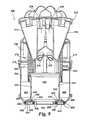
- FIG. 3is a side section taken along the line A-A of FIG. 2 showing the cyclonic separating apparatus removed from the cylinder vacuum cleaner of FIG. 1 ;
- FIG. 4is perspective view of a seal of the cyclonic separating apparatus of FIG. 3 ;
- FIG. 5is a side section of the seal of FIG. 4 ;
- FIG. 6is an enlarged view of a part of FIG. 5 ;
- FIG. 7is a side section of a closure member forming part of the cyclonic separating apparatus of FIG. 3 ;
- FIG. 8is a side section of the cyclonic separating apparatus of FIG. 3 , with the closure member in an open state;
- FIG. 9is a side section through cyclonic separating apparatus according to a second embodiment of the invention.
- FIGS. 1 and 2A cylinder vacuum cleaner 10 incorporating cyclonic separating apparatus according to a first embodiment of the invention is shown in FIGS. 1 and 2 .
- the vacuum cleaner 10has a main body 12 housing a motor and fan unit (not shown) and to which a pair of wheels 14 is attached.
- the wheels 14allow the main body 12 of the vacuum cleaner 10 to be manoeuvred across a floor surface.
- a dirty air inlet 16is formed on the main body 12 .
- a hose and wand assembly(not shown) can be connected to the dirty air inlet 16 in order to enable a user to clean a floor surface.
- Cyclonic separating apparatus 100is releasably attached to the main body 12 .
- the interior of the cyclonic separating apparatus 100is in communication with the dirty air inlet 16 through which a dirt-laden airflow enters the cyclonic separating apparatus 100 .
- the cyclonic separating apparatus 100can be removed from the main body 12 for emptying purposes.
- the cyclonic separating apparatus 100is shown in more detail in FIG. 3 , in which the cyclonic separating apparatus 100 is shown removed from the remainder of the vacuum cleaner 10 for clarity.
- the cyclonic separating apparatus 100comprises a substantially cylindrical outer wall 102 .
- the outer wall 102defines a first cyclonic separator 104 and a first collector 106 . Dirt and dust is both separated by the first cyclonic separator 104 and collected in the first collector 106 in this region.
- An inlet 108is formed in the outer wall 102 .
- the inlet 108forms a communication path between the dirty air inlet 16 and the interior of the first cyclonic separator 104 .
- the air inlet 108is arranged tangentially to the first cyclonic separator 104 so that the incoming air is forced to follow a helical path around the interior of the outer wall 102 .
- a shroud 110is located inwardly of the outer wall 102 of the first cyclonic separator 104 .
- the shroud 110comprises a cylindrical wall 112 having a plurality of through-holes 114 .
- the shroud 110surrounds an outlet 116 from the first cyclonic separator 104 .
- the outlet 116provides a communication path between the first cyclonic separator 104 and a second cyclonic separator 118 .
- a lip 120is provided at the base of the shroud 110 . The lip 120 helps prevent separated dirt and dust from being re-entrained back into the airflow within the first cyclonic separator 104 .
- the second cyclonic separator 118comprises a single cyclone 122 .
- the single cyclone 122has an air inlet 124 and an air outlet 126 , both of which are located at a first end of the single cyclone 122 .
- a cone opening 128is located at a second end of the single cyclone 122 .
- a second collector 130is also located at the second end of the single cyclone 122 and is in communication with the cone opening 128 .
- the second collector 130is delimited by a cylindrical wall 132 which depends from an outer surface of the single cyclone 122 and which is located inwardly of the shroud 110 .
- the air outlet 126 of the single cyclone 122is in communication with a duct 134 .
- the duct 134provides a communication path between the second cyclonic separator 118 and a third cyclonic separator 136 .
- the third cyclonic separator 136comprises a plurality of high-efficiency cyclones 138 arranged in parallel. In this embodiment, fourteen high-efficiency cyclones 138 are provided. Each high-efficiency cyclone 138 has a tangentially-arranged air inlet 140 and an air outlet 142 . Each air inlet 140 and air outlet 142 is located at a first end of the respective high-efficiency cyclone 138 . A cone opening (not shown) is located at a second end of each high-efficiency cyclone 138 .
- a third collector 144is located at the second end of the high-efficiency cyclones 138 and is in communication with the cone openings of the high-efficiency cyclones 138 .
- the third collector 144is delimited by the cylindrical wall 132 and a cylindrical wall 146 which is located between the shroud 110 and the cylindrical wall 132 .
- the cylindrical wall 146depends from an upper part of the shroud 110 and is also connected to the shroud at a point approximately half way down the cylindrical wall 146 . Therefore, the third collector 144 is an annular chamber located between the first collector 106 and the second collector 130 .
- the first, second and third collectors 106 , 130 , 144are arranged concentrically.
- the second and third collectors 130 , 144are arranged inside the first collector 106 .
- the second collector 130is also arranged inside the third collector 144 .
- the ends of the collectors 106 , 130 , 144are separated by dividing walls 132 , 146 .
- the ends of the first and third collectors 106 , 144are divided by cylindrical wall 146
- the ends of the second and third collectors 130 , 144are divided by cylindrical wall 132 .
- the air outlets 142 of the high-efficiency cyclones 138are in communication with an outlet 148 .
- the outlet 148provides an airflow path from the cyclonic separating apparatus 100 into other parts of the vacuum cleaner 10 .
- Located downstream of the outlet 148is a pre-motor filter (not shown), the motor and fan unit and a post-motor filter (not shown).
- a closure member 150closes the lower end of the cyclonic separating apparatus 100 .
- the closure member 150is pivotably mounted on the lower end of the outer wall 102 by means of a hinge 152 .
- the closure member 150is retained in a closed position (as shown in FIG. 3 ) by means of a catch 154 .
- the closure member 150comprises a base 155 and an inner annular wall 156 extending into the second collector 130 .
- the inner annular wall 156helps to reduce the risk of dirt and dust separated by the single cyclone 122 of the second cyclonic separator 118 being re-entrained into the airflow leaving the single cyclone 122 .
- the closure member 150also includes four further annular walls 158 concentric with and arranged radially outside the inner annular wall 156 . Adjacent annular walls 158 delimit three concentric, annular channels 160 , 162 , 164 .
- the three annular channels 160 , 162 , 164comprise a relatively wide channel 162 flanked by two relatively narrow channels 160 , 164 .
- annular seal 166is attached to the closure member 150 .
- the annular seal 166is shown in more detail in FIGS. 4 to 6 . In these figures, the annular seal 166 is shown removed from the remainder of the cyclonic separating apparatus 100 .
- the annular seal 166has a convex upper surface 168 and two side walls 170 which depend therefrom.
- the annular seal 166is manufactured from a flexible material such as a rubber.
- the convex upper surface 168has an increased thickness towards the uppermost portion thereof.
- the side walls 170have a sawtooth profile on both an internal surface 172 and an external surface 174 thereof. This is shown most clearly in FIG. 6 .
- the sawtooth profilecomprises two teeth which define two circumferential grooves around the internal surfaces 172 of the side walls 170 .
- the sawtooth profile on the external surfaces 174comprises four smaller teeth which define four circumferential grooves around the external surfaces 174 .
- FIG. 7shows a cross-section of the closure member 150 with the annular seal 166 attached thereto.
- Each side wall 170 of the annular seal 166is located in a respective relatively narrow annular channel 160 , 164 of the closure member 150 .
- the annular seal 166is held in place by the engagement of the teeth located on the inner and outer surfaces 172 , 174 of the side walls 170 of the annular seal 166 with the annular walls 158 of the closure member 150 .
- the upper surface 168 of the annular seal 166covers the relatively wide annular channel 162 of the closure member 150 to define a cavity 175 .
- a plurality of through-holes 176are formed in the base 155 of the closure member 150 to provide a communication path between the cavity 175 and the external atmosphere. Therefore, the cavity 175 will remain at atmospheric pressure, irrespective of the pressure inside the cyclonic separating apparatus 100 . However, due to the speed of the airflow within the cyclonic separating apparatus 100 , the pressure within the cyclonic separating apparatus 100 will be below atmospheric, resulting in a pressure drop across the upper surface 168 of the annular seal 166 . Due to its flexible nature, the annular seal 166 will change shape depending upon the magnitude of the pressure difference established across the convex upper surface 168 thereof.
- the annular seal 166is an expandable seal as it is able to expand, or inflate, when there is a positive pressure in the cavity relative to that within the cyclonic separating apparatus 100 .
- the operation of the annular seal 166is described in more detail below.
- the annular seal 166is shown in a “relaxed” position in FIG. 7 , in which there is no pressure difference across the convex upper surface 168 of the annular seal 166 .
- the closure member 150is closed (as shown in FIG. 3 )
- the upper surface 168 of the annular seal 166will be compressed by the ends of the cylindrical walls 132 , 146 to effect a seal between closure member 150 and the three collectors 106 , 130 , 144 even when there is no pressure drop across the upper surface 168 of the annular seal 166 .
- the motor and fan unitdraws a flow of dirt-laden air through the hose and wand, into the dirty air inlet 16 , through the inlet 108 and into the cyclonic separating apparatus 100 . Due to the tangential arrangement of the inlet 108 , the airflow is forced to follow a helical path around the interior of the outer wall 102 . Therefore, larger dirt and dust particles are separated by cyclonic motion in the first cyclonic separator 104 . These particles are collected in the first collector 106 .
- the partially-cleaned airflowthen flows back up the interior of the first cyclonic separator 104 and exits the first cyclonic separator 104 via the through-holes 114 in the shroud 110 .
- the airflowOnce the airflow has passed through the shroud 110 , it enters the outlet 116 and from there enters the inlet 124 of the single cyclone 122 of the second cyclonic separator 118 .
- the single cyclone 122has a diameter smaller than the outer wall 102 of the first cyclonic separator 104 and is tapered. Therefore, the single cyclone 122 is able to separate smaller particles of dirt and dust from the partially-cleaned airflow than the first cyclonic separator 104 .
- the airflowis then divided between the tangential air inlets 140 of the high-efficiency cyclones 138 of the third cyclonic separator 136 .
- Each of the high-efficiency cyclones 138has a diameter smaller than that of both the first cyclonic separator 104 and the single cyclone 122 of the second cyclonic separator 118 . Therefore, the high-efficiency cyclones 138 are able to separate even finer particles of dirt and dust from the airflow than either of the first or second cyclonic separators 104 , 118 . Separated dirt and dust exits the high-efficiency cyclones 138 via the cone openings and passes into the third collector 144 where it is collected.
- Cleaned airthen flows back up the high-efficiency cyclones 138 , exits the high-efficiency cyclones 138 through the air outlets 142 and enters the outlet 148 .
- the cleaned airthen passes from the outlet 148 sequentially through the pre-motor filter, the motor and fan unit, and the post-motor filter before being exhausted from the vacuum cleaner 10 through the air vents (not shown) located on the outer surface of the vacuum cleaner 10 .
- the speed of the airflow within the cyclonic separating apparatus 100will be greater than the speed of the atmospheric air surrounding the vacuum cleaner 10 . Therefore, the air pressure within the cyclonic separating apparatus 100 will be lower than atmospheric pressure. Consequently, there will be a pressure drop (or differential) across the convex upper surface 168 of the annular seal 166 .
- the pressure in the cavity 175 beneath the annular seal 166will be positive relative to the pressure in the cyclonic separating apparatus 100 . This will cause the annular seal 166 to expand, or inflate, and push upwards against the ends of the cylindrical walls 132 , 146 .
- the annular seal 166is able to seal effectively between the three separate collectors 106 , 130 , 144 even if the collectors 106 , 130 , 144 are not fully sealed when the vacuum cleaner 10 is switched off; for example, due to a worn seal, a misaligned closure member 150 or the presence of dirt and dust between the annular seal 166 and the cylindrical walls 132 , 146 .
- the collectors 106 , 130 , 144 of the cyclonic separating apparatus 100may be full of dirt and dust, and require emptying. To do this, the user switches off the vacuum cleaner 10 .
- the vacuum cleaner 10When the vacuum cleaner 10 is switched off, the air pressure within the cyclonic separating apparatus 100 will return to atmospheric pressure. Therefore, there will be no pressure drop across the upper surface 168 of the annular seal 166 and so the annular seal 166 will contract, or deflate.
- the userreleases the cyclonic separating apparatus 100 from the main body 12 by pressing a release button (not shown), removes the cyclonic separating apparatus 100 from the remainder of the vacuum cleaner 10 and places it over a suitable receptacle such as a dustbin. The user then presses a further release button (not shown) in order to release the catch 154 .
- the usermanually moves the closure member 150 back into the closed position shown in FIG. 3 .
- the cyclonic separating apparatus 100can then be replaced on the main body 12 of the vacuum cleaner 10 (as shown in FIGS. 1 and 2 ) for further cleaning operations.
- FIG. 9shows a side section through cyclonic separating apparatus 200 according to a second embodiment of the invention.
- the cyclonic separating apparatus 200is suitable for use in the vacuum cleaner 10 of FIG. 1 in place of the cyclonic separating apparatus 100 of the first embodiment.
- the cyclonic separating apparatus 200differs from the cyclonic separating apparatus 100 of the first embodiment in that the cyclonic separating apparatus 200 has only two cyclonic separators.
- the cyclonic separating apparatus 200comprises a substantially cylindrical outer wall 202 .
- the outer wall 202defines a first cyclonic separator 204 and a first collector 206 .
- An inlet 208is formed in the outer wall 202 .
- the inlet 208is arranged tangentially to the first cyclonic separator 204 in the manner of the inlet 108 of the first embodiment.
- a shroud 210is located inwardly of the outer wall 202 .
- the shroud 210is similar to the shroud 110 of the first embodiment and will not be described any further.
- a passageway 212is located downstream of the shroud 210 and provides a communication path between the first cyclonic separator 204 and a second cyclonic separator 214 .
- the second cyclonic separator 214comprises a plurality of high-efficiency cyclones 216 arranged in parallel. In this embodiment, six high-efficiency cyclones 216 are provided. Each high-efficiency cyclone 216 has a cone opening 218 in communication with a second collector 220 .
- the second collector 220is delimited by a cylindrical wall 222 which depends from a lower part of the shroud 210 .
- the first and second collectors 206 , 220are arranged concentrically, with the second collector 220 being arranged inside the first collector 206 .
- the ends of the collectors 206 , 220are separated by the dividing wall 222 .
- a closure member 224closes the lower end of the cyclonic separating apparatus 200 .
- the closure member 224is pivotably mounted on the lower end of the outer wall 202 in a similar manner to the closure member 150 of the first embodiment.
- the closure member 224includes four annular walls 226 which delimit three concentric, annular channels 228 , 230 , 232 .
- the three annular channels 228 , 230 , 232comprise a relatively wide channel 230 flanked by two relatively narrow channels 228 , 232 .
- annular seal 234is attached to the closure member 224 .
- the annular seal 234is the same as the annular seal 166 of the first embodiment. However, in this embodiment, the annular seal 234 only seals between the closure member 224 and a single dividing wall 222 .
- an upper surface 236 of the annular seal 234covers the relatively wide annular channel 230 of the closure member 224 to define a cavity 238 .
- a plurality of through-holes 240are formed in the closure member 224 to provide a communication path between the cavity 238 and the external atmosphere. Therefore, the cavity 238 will remain at atmospheric pressure irrespective of the pressure inside the cyclonic separating apparatus 200 .
- the annular seal 234is shown in a “relaxed” position in FIG. 9 , in which there is no pressure difference across an upper surface 236 of the annular seal 234 .
- the annular seal 234will change shape depending upon the magnitude of the pressure difference established across the upper surface 236 thereof when the vacuum cleaner 10 is switched on.
- a flow of dirt and dust laden airflows through the inlet 208 and into the cyclonic separating apparatus 200 .
- Larger dirt and dust particlesare separated by cyclonic motion in the first cyclonic separator 204 , and these particles are collected in the first collector 206 .
- the partially-cleaned airflowexits the first cyclonic separator 204 via through-holes (not shown) in the shroud 210 , and is divided between the plurality of high-efficiency cyclones 216 of the second cyclonic separator 214 . Dirt and dust is separated in the high-efficiency cyclones 216 and exits via the cone openings 218 to be collected in the second collector 220 .
- the cleaned airthen passes back up through the plurality of high-efficiency cyclones 216 and out of the cyclonic separating apparatus 200 .
- the remainder of the operation of the cyclonic separating apparatus 200is identical to that of the cyclonic separating apparatus 100 as described in the first embodiment.
- the pressure in the cavity 238 beneath the annular seal 234will be positive relative to the pressure in the cyclonic separating apparatus 200 . Therefore, the annular seal 234 will expand—the upper surface 236 will be pushed upwards to seal against the end of the dividing wall 222 . Therefore, the annular seal 236 is able to seal effectively between the two separate collectors 206 , 220 even if the collectors 206 , 220 are not fully sealed when the vacuum cleaner 10 is switched off.
- the inventionis not limited to the detailed description given above. Variations will be apparent to the person skilled in the art.
- the sealneed not be expandable, or inflatable, in response to a pressure difference across a surface of the seal.
- a thermally-expandable seal which expands when heatedmay be used.
- the sealneed not be annular. Other arrangements, for example, square, rectangular or cylindrical shapes could be used.
- the sealmay also take the form of a sheet.
- More than one sealmay be used; for example, an individual expandable seal may be located between each dividing wall and the closure member. Additionally, the seal need not be located on the closure member. Other arrangements could be used; for example, the seal could be located on the end of the dividing wall between collectors, or may be located on a separate member between the dividing walls and the closure member.
- a part of the cyclonic separating apparatus other than the basemay be movable for emptying purposes.
- Other forms, arrangements and locations of closure membersmay be used.
- the side or top of the cyclonic separating apparatusmay be movable (or openable).
- the closure memberneed not be pivotable.
- Other opening arrangements for the closure membermay be used; for example, sliding, retracting or rotating closure members.
- More than three cyclonic separatorsmay be provided. Additionally, more than one collector may be provided with a cyclonic separator. For example, two cyclonic separators may be provided with one of the cyclonic separators having two collectors associated therewith. Further, any number of cyclones may be used in each cyclonic separator.
- the cleaning applianceneed not be a cylinder vacuum cleaner.
- the inventionis applicable to other types of vacuum cleaner, for example, upright machines, stick-vacuums or hand-held cleaners. Further, the present invention is applicable to other types of cleaning appliances, for example, a wet and dry machine or a carpet shampooer.
Landscapes
- Engineering & Computer Science (AREA)
- Mechanical Engineering (AREA)
- Filters For Electric Vacuum Cleaners (AREA)
- Cyclones (AREA)
Abstract
Description
Claims (15)
Applications Claiming Priority (2)
| Application Number | Priority Date | Filing Date | Title |
|---|---|---|---|
| GB0720341.7 | 2007-10-18 | ||
| GB0720341.7AGB2453761B (en) | 2007-10-18 | 2007-10-18 | Cyclonic separating apparatus for a cleaning appliance |
Publications (2)
| Publication Number | Publication Date |
|---|---|
| US20090100633A1 US20090100633A1 (en) | 2009-04-23 |
| US7867307B2true US7867307B2 (en) | 2011-01-11 |
Family
ID=38814013
Family Applications (1)
| Application Number | Title | Priority Date | Filing Date |
|---|---|---|---|
| US12/243,484Active2029-06-19US7867307B2 (en) | 2007-10-18 | 2008-10-01 | Cyclonic separating apparatus for a cleaning appliance |
Country Status (8)
| Country | Link |
|---|---|
| US (1) | US7867307B2 (en) |
| EP (1) | EP2205137B1 (en) |
| JP (1) | JP4696320B2 (en) |
| KR (1) | KR101153986B1 (en) |
| CN (1) | CN101455543B (en) |
| AU (1) | AU2008313526C1 (en) |
| GB (1) | GB2453761B (en) |
| WO (1) | WO2009050428A1 (en) |
Cited By (31)
| Publication number | Priority date | Publication date | Assignee | Title |
|---|---|---|---|---|
| US20090100634A1 (en)* | 2007-10-18 | 2009-04-23 | Dyson Technology Limited | Cyclonic separating apparatus for a cleaning appliance |
| US20090100810A1 (en)* | 2007-10-23 | 2009-04-23 | David Benjamin Smith | Cyclonic separation apparatus |
| US20120210537A1 (en)* | 2011-02-18 | 2012-08-23 | Makarov Sergey V | Vacuum cleaner dirt cup |
| USD703017S1 (en) | 2011-01-07 | 2014-04-22 | Black & Decker Inc. | Screwdriver |
| USD705504S1 (en)* | 2013-02-18 | 2014-05-20 | Dyson Technology Limited | Vacuum cleaner |
| USD708408S1 (en)* | 2013-02-18 | 2014-07-01 | Dyson Technology Limited | Part of a vacuum cleaner |
| USD708802S1 (en)* | 2013-02-18 | 2014-07-08 | Dyson Technology Limited | Part of a vacuum cleaner |
| USD709253S1 (en)* | 2012-08-28 | 2014-07-15 | Samsung Electronics Co., Ltd. | Vacuum cleaner |
| USD718912S1 (en)* | 2013-02-18 | 2014-12-02 | Dyson Technology Limited | Vacuum cleaner |
| USD724799S1 (en)* | 2012-08-28 | 2015-03-17 | Samsung Electronics Co. Ltd. | Vacuum cleaner |
| US9199362B2 (en) | 2010-01-07 | 2015-12-01 | Black & Decker Inc. | Power tool having rotary input control |
| US9266178B2 (en) | 2010-01-07 | 2016-02-23 | Black & Decker Inc. | Power tool having rotary input control |
| US20160150929A1 (en)* | 2014-12-01 | 2016-06-02 | Lg Electronics Inc. | Vacuum cleaner and dust collecting apparatus |
| USD767220S1 (en) | 2013-12-20 | 2016-09-20 | Dyson Technology Limited | Part of a vacuum cleaner |
| USD767219S1 (en) | 2013-12-20 | 2016-09-20 | Dyson Technology Limited | Part of a vacuum cleaner |
| US9475180B2 (en) | 2010-01-07 | 2016-10-25 | Black & Decker Inc. | Power tool having rotary input control |
| US9693665B2 (en) | 2014-10-22 | 2017-07-04 | Techtronic Industries Co. Ltd. | Vacuum cleaner having cyclonic separator |
| US9775483B2 (en) | 2014-10-22 | 2017-10-03 | Techtronic Industries Co. Ltd. | Vacuum cleaner having cyclonic separator |
| US9885194B1 (en) | 2017-05-11 | 2018-02-06 | Hayward Industries, Inc. | Pool cleaner impeller subassembly |
| US9885196B2 (en) | 2015-01-26 | 2018-02-06 | Hayward Industries, Inc. | Pool cleaner power coupling |
| US9896858B1 (en) | 2017-05-11 | 2018-02-20 | Hayward Industries, Inc. | Hydrocyclonic pool cleaner |
| US9909333B2 (en) | 2015-01-26 | 2018-03-06 | Hayward Industries, Inc. | Swimming pool cleaner with hydrocyclonic particle separator and/or six-roller drive system |
| US9918602B2 (en) | 2011-04-15 | 2018-03-20 | Dyson Technology Limited | Cyclonic separator |
| USD813475S1 (en) | 2016-06-01 | 2018-03-20 | Milwaukee Electric Tool Corporation | Handheld vacuum cleaner |
| US10080471B2 (en) | 2015-12-21 | 2018-09-25 | Electrolux Home Care Products, Inc. | Versatile vacuum cleaners |
| US10117551B2 (en) | 2014-10-22 | 2018-11-06 | Techtronic Industries Co. Ltd. | Handheld vacuum cleaner |
| US10123673B2 (en)* | 2015-01-16 | 2018-11-13 | Lg Electronics Inc. | Dust collecting apparatus |
| US10156083B2 (en) | 2017-05-11 | 2018-12-18 | Hayward Industries, Inc. | Pool cleaner power coupling |
| US10631697B2 (en) | 2014-02-14 | 2020-04-28 | Techtronic Industries Co. Ltd. | Separator configuration |
| US11064855B2 (en)* | 2016-08-25 | 2021-07-20 | Lg Electronics Inc. | Cleaner |
| US12121198B2 (en) | 2014-12-17 | 2024-10-22 | Omachron Intellectual Property Inc. | Surface cleaning apparatus |
Families Citing this family (56)
| Publication number | Priority date | Publication date | Assignee | Title |
|---|---|---|---|---|
| CA2599303A1 (en) | 2007-08-29 | 2009-02-28 | Gbd Corp. | Surface cleaning apparatus |
| US9888817B2 (en) | 2014-12-17 | 2018-02-13 | Omachron Intellectual Property Inc. | Surface cleaning apparatus |
| US11857142B2 (en) | 2006-12-15 | 2024-01-02 | Omachron Intellectual Property Inc. | Surface cleaning apparatus having an energy storage member and a charger for an energy storage member |
| US10165912B2 (en) | 2006-12-15 | 2019-01-01 | Omachron Intellectual Property Inc. | Surface cleaning apparatus |
| US9192269B2 (en) | 2006-12-15 | 2015-11-24 | Omachron Intellectual Property Inc. | Surface cleaning apparatus |
| US20210401246A1 (en) | 2016-04-11 | 2021-12-30 | Omachron Intellectual Property Inc. | Surface cleaning apparatus |
| CA2658046A1 (en)* | 2009-03-11 | 2010-09-11 | G.B.D. Corp. | Surface cleaning apparatus |
| US9433332B2 (en) | 2013-02-27 | 2016-09-06 | Omachron Intellectual Property Inc. | Surface cleaning apparatus |
| US10722086B2 (en) | 2017-07-06 | 2020-07-28 | Omachron Intellectual Property Inc. | Handheld surface cleaning apparatus |
| US12156626B2 (en) | 2009-03-13 | 2024-12-03 | Omachron Intellectual Property Inc. | Surface cleaning apparatus |
| US9265395B2 (en) | 2010-03-12 | 2016-02-23 | Omachron Intellectual Property Inc. | Surface cleaning apparatus |
| US8402599B2 (en) | 2010-09-01 | 2013-03-26 | Techtronic Floor Care Technology Limited | Vacuum cleaner dirt cup and seal |
| GB2490694B (en) | 2011-05-11 | 2015-01-14 | Dyson Technology Ltd | A surface treating appliance |
| GB2490695B (en) | 2011-05-11 | 2015-01-14 | Dyson Technology Ltd | A surface treating appliance |
| GB2492744B (en) | 2011-05-11 | 2014-12-24 | Dyson Technology Ltd | A multi-cyclonic surface treating appliance |
| GB2490692B (en) | 2011-05-11 | 2014-12-17 | Dyson Technology Ltd | A cyclonic surface treating appliance with multiple cyclones |
| GB2492743B (en) | 2011-05-11 | 2015-01-14 | Dyson Technology Ltd | A surface treating appliance |
| GB2490693B (en) | 2011-05-11 | 2014-12-17 | Dyson Technology Ltd | A cyclonic surface treating appliance with multiple cyclones |
| GB2490697B (en) | 2011-05-11 | 2015-01-14 | Dyson Technology Ltd | A surface treating appliance |
| GB2490696B (en) | 2011-05-11 | 2014-12-17 | Dyson Technology Ltd | A cyclonic surface treating appliance with multiple cyclones |
| US9320401B2 (en) | 2013-02-27 | 2016-04-26 | Omachron Intellectual Property Inc. | Surface cleaning apparatus |
| US9027198B2 (en) | 2013-02-27 | 2015-05-12 | G.B.D. Corp. | Surface cleaning apparatus |
| US9591958B2 (en) | 2013-02-27 | 2017-03-14 | Omachron Intellectual Property Inc. | Surface cleaning apparatus |
| US9585530B2 (en) | 2014-07-18 | 2017-03-07 | Omachron Intellectual Property Inc. | Portable surface cleaning apparatus |
| US9451853B2 (en) | 2014-07-18 | 2016-09-27 | Omachron Intellectual Property Inc. | Portable surface cleaning apparatus |
| US9420925B2 (en) | 2014-07-18 | 2016-08-23 | Omachron Intellectual Property Inc. | Portable surface cleaning apparatus |
| US9314139B2 (en) | 2014-07-18 | 2016-04-19 | Omachron Intellectual Property Inc. | Portable surface cleaning apparatus |
| KR102117003B1 (en)* | 2014-08-07 | 2020-06-09 | 삼성전자주식회사 | Cleaner and dust separating device applying the same |
| WO2016021874A1 (en)* | 2014-08-07 | 2016-02-11 | Samsung Electronics Co., Ltd. | Cleaner and dust separating device applying the same |
| US10251519B2 (en) | 2014-12-17 | 2019-04-09 | Omachron Intellectual Property Inc. | Surface cleaning apparatus |
| US10136778B2 (en) | 2014-12-17 | 2018-11-27 | Omachron Intellectual Property Inc. | Surface cleaning apparatus |
| GB2546543B (en)* | 2016-01-22 | 2019-01-02 | Dyson Technology Ltd | Separating apparatus and vacuum cleaner |
| US9936846B2 (en)* | 2016-04-25 | 2018-04-10 | Omachron Intellectual Property Inc. | Cyclone assembly for surface cleaning apparatus and a surface cleaning apparatus having same |
| US10251521B2 (en) | 2016-04-25 | 2019-04-09 | Omachron Intellectual Property Inc. | Cyclone assembly for surface cleaning apparatus and a surface cleaning apparatus having same |
| US10149587B2 (en) | 2016-04-25 | 2018-12-11 | Omachron Intellectual Property Inc. | Cyclone assembly for surface cleaning apparatus and a surface cleaning apparatus having same |
| US10537219B2 (en) | 2016-04-25 | 2020-01-21 | Omachron Intellectual Property Inc. | Cyclone assembly for surface cleaning apparatus and a surface cleaning apparatus having same |
| US10201260B2 (en) | 2016-04-25 | 2019-02-12 | Omachron Intellectual Property Inc. | Cyclone assembly for surface cleaning apparatus and a surface cleaning apparatus having same |
| EP3641610B1 (en)* | 2017-06-19 | 2023-03-15 | Techtronic Floor Care Technology Limited | Cyclonic separator device |
| GB2563664B (en)* | 2017-06-23 | 2019-09-04 | Dyson Technology Ltd | Separating apparatus and vacuum cleaner |
| US11766156B2 (en) | 2020-03-18 | 2023-09-26 | Omachron Intellectual Property Inc. | Surface cleaning apparatus with removable air treatment member assembly |
| US10506904B2 (en) | 2017-07-06 | 2019-12-17 | Omachron Intellectual Property Inc. | Handheld surface cleaning apparatus |
| US11445878B2 (en) | 2020-03-18 | 2022-09-20 | Omachron Intellectual Property Inc. | Surface cleaning apparatus with removable air treatment member assembly |
| US10537216B2 (en) | 2017-07-06 | 2020-01-21 | Omachron Intellectual Property Inc. | Handheld surface cleaning apparatus |
| US10702113B2 (en) | 2017-07-06 | 2020-07-07 | Omachron Intellectual Property Inc. | Handheld surface cleaning apparatus |
| US10842330B2 (en) | 2017-07-06 | 2020-11-24 | Omachron Intellectual Property Inc. | Handheld surface cleaning apparatus |
| US10631693B2 (en) | 2017-07-06 | 2020-04-28 | Omachron Intellectual Property Inc. | Handheld surface cleaning apparatus |
| US11666193B2 (en) | 2020-03-18 | 2023-06-06 | Omachron Intellectual Property Inc. | Surface cleaning apparatus with removable air treatment member assembly |
| US11730327B2 (en) | 2020-03-18 | 2023-08-22 | Omachron Intellectual Property Inc. | Surface cleaning apparatus with removable air treatment assembly |
| US10750913B2 (en) | 2017-07-06 | 2020-08-25 | Omachron Intellectual Property Inc. | Handheld surface cleaning apparatus |
| US10882059B2 (en) | 2018-09-21 | 2021-01-05 | Omachron Intellectual Property Inc. | Multi cyclone array for surface cleaning apparatus and a surface cleaning apparatus having same |
| US11192122B2 (en) | 2018-08-13 | 2021-12-07 | Omachron Intellectual Property Inc. | Cyclonic air treatment member and surface cleaning apparatus including the same |
| US11013384B2 (en) | 2018-08-13 | 2021-05-25 | Omachron Intellectual Property Inc. | Cyclonic air treatment member and surface cleaning apparatus including the same |
| US11006799B2 (en) | 2018-08-13 | 2021-05-18 | Omachron Intellectual Property Inc. | Cyclonic air treatment member and surface cleaning apparatus including the same |
| AU2021237991B2 (en) | 2020-03-18 | 2024-08-01 | Omachron Intellectual Property Inc. | Surface cleaning apparatus with removable air treatment member assembly |
| CN112122019B (en)* | 2020-09-02 | 2021-10-15 | 东莞福莱仕智能电子科技有限公司 | Cyclone separation device and cleaning equipment |
| CN215128031U (en)* | 2021-03-11 | 2021-12-14 | 北京顺造科技有限公司 | A cyclone separation device |
Citations (12)
| Publication number | Priority date | Publication date | Assignee | Title |
|---|---|---|---|---|
| US3486618A (en) | 1966-09-13 | 1969-12-30 | Nils Anders Lennart Wikdahl | Multiple-cyclone separator installation |
| US4687497A (en) | 1986-09-29 | 1987-08-18 | Mobil Oil Corporation | Solids-gas separator |
| US5000767A (en)* | 1990-05-30 | 1991-03-19 | Pneumafil Corporation | Dust collector with pneumatic seal |
| WO2002067742A2 (en) | 2001-02-24 | 2002-09-06 | Dyson Ltd | A collecting chamber for a vacuum cleaner |
| JP2002326041A (en) | 2001-05-08 | 2002-11-12 | Matsushita Electric Ind Co Ltd | Centrifugal dust collector and vacuum cleaner using the same |
| JP2003156002A (en) | 2001-11-21 | 2003-05-30 | Nok Corp | Accumulator |
| US6607572B2 (en)* | 2001-02-24 | 2003-08-19 | Dyson Limited | Cyclonic separating apparatus |
| JP2003528704A (en) | 2000-03-31 | 2003-09-30 | ダイソン・リミテッド | Apparatus for separating particles from a fluid stream |
| GB2386827A (en) | 2002-03-26 | 2003-10-01 | White Cons Ltd | Filtration arrangement for a cyclonic vacuum cleaner |
| JP2004229827A (en) | 2003-01-29 | 2004-08-19 | Sanyo Electric Co Ltd | Dust collecting device and vacuum cleaner using it |
| KR20070012988A (en) | 2005-07-25 | 2007-01-30 | 엘지전자 주식회사 | Dust collection unit |
| GB2441300A (en) | 2006-09-01 | 2008-03-05 | Dyson Technology Ltd | A collection chamber for a vacuum cleaner |
- 2007
- 2007-10-18GBGB0720341.7Apatent/GB2453761B/enactiveActive
- 2008
- 2008-10-01USUS12/243,484patent/US7867307B2/enactiveActive
- 2008-10-06KRKR1020107008891Apatent/KR101153986B1/enactiveActive
- 2008-10-06EPEP08806518.0Apatent/EP2205137B1/enactiveActive
- 2008-10-06AUAU2008313526Apatent/AU2008313526C1/enactiveActive
- 2008-10-06WOPCT/GB2008/003376patent/WO2009050428A1/enactiveApplication Filing
- 2008-10-17JPJP2008268779Apatent/JP4696320B2/enactiveActive
- 2008-10-20CNCN2008101911849Apatent/CN101455543B/enactiveActive
Patent Citations (13)
| Publication number | Priority date | Publication date | Assignee | Title |
|---|---|---|---|---|
| US3486618A (en) | 1966-09-13 | 1969-12-30 | Nils Anders Lennart Wikdahl | Multiple-cyclone separator installation |
| US4687497A (en) | 1986-09-29 | 1987-08-18 | Mobil Oil Corporation | Solids-gas separator |
| US5000767A (en)* | 1990-05-30 | 1991-03-19 | Pneumafil Corporation | Dust collector with pneumatic seal |
| US6835222B2 (en) | 2000-03-31 | 2004-12-28 | Dyson Limited | Apparatus for separating particles from fluid flow |
| JP2003528704A (en) | 2000-03-31 | 2003-09-30 | ダイソン・リミテッド | Apparatus for separating particles from a fluid stream |
| US6607572B2 (en)* | 2001-02-24 | 2003-08-19 | Dyson Limited | Cyclonic separating apparatus |
| WO2002067742A2 (en) | 2001-02-24 | 2002-09-06 | Dyson Ltd | A collecting chamber for a vacuum cleaner |
| JP2002326041A (en) | 2001-05-08 | 2002-11-12 | Matsushita Electric Ind Co Ltd | Centrifugal dust collector and vacuum cleaner using the same |
| JP2003156002A (en) | 2001-11-21 | 2003-05-30 | Nok Corp | Accumulator |
| GB2386827A (en) | 2002-03-26 | 2003-10-01 | White Cons Ltd | Filtration arrangement for a cyclonic vacuum cleaner |
| JP2004229827A (en) | 2003-01-29 | 2004-08-19 | Sanyo Electric Co Ltd | Dust collecting device and vacuum cleaner using it |
| KR20070012988A (en) | 2005-07-25 | 2007-01-30 | 엘지전자 주식회사 | Dust collection unit |
| GB2441300A (en) | 2006-09-01 | 2008-03-05 | Dyson Technology Ltd | A collection chamber for a vacuum cleaner |
Non-Patent Citations (2)
| Title |
|---|
| GB Search Report, dated Feb. 12, 2008, directed to corresponding GB Patent Application No. GB0720341.7; 1 page. |
| International Search Report and Written Opinion mailed on Jan. 5, 2009, directed to counterpart International Patent Application No. PCT/GB2008/003376; 14 pages. |
Cited By (54)
| Publication number | Priority date | Publication date | Assignee | Title |
|---|---|---|---|---|
| US8375509B2 (en) | 2007-10-18 | 2013-02-19 | Dyson Technology Limited | Cyclonic separating apparatus for a cleaning appliance |
| US20090100634A1 (en)* | 2007-10-18 | 2009-04-23 | Dyson Technology Limited | Cyclonic separating apparatus for a cleaning appliance |
| US20090100810A1 (en)* | 2007-10-23 | 2009-04-23 | David Benjamin Smith | Cyclonic separation apparatus |
| US7976597B2 (en)* | 2007-10-23 | 2011-07-12 | Hoover Limited | Cyclonic separation apparatus |
| US9321156B2 (en) | 2010-01-07 | 2016-04-26 | Black & Decker Inc. | Power tool having rotary input control |
| US9199362B2 (en) | 2010-01-07 | 2015-12-01 | Black & Decker Inc. | Power tool having rotary input control |
| US9266178B2 (en) | 2010-01-07 | 2016-02-23 | Black & Decker Inc. | Power tool having rotary input control |
| US9211636B2 (en) | 2010-01-07 | 2015-12-15 | Black & Decker Inc. | Power tool having rotary input control |
| US10160049B2 (en) | 2010-01-07 | 2018-12-25 | Black & Decker Inc. | Power tool having rotary input control |
| US9475180B2 (en) | 2010-01-07 | 2016-10-25 | Black & Decker Inc. | Power tool having rotary input control |
| US9321155B2 (en) | 2010-01-07 | 2016-04-26 | Black & Decker Inc. | Power tool having switch and rotary input control |
| USD703017S1 (en) | 2011-01-07 | 2014-04-22 | Black & Decker Inc. | Screwdriver |
| US8689401B2 (en)* | 2011-02-18 | 2014-04-08 | Techtronic Floor Care Technology Limited | Vacuum cleaner dirt cup |
| US20120210537A1 (en)* | 2011-02-18 | 2012-08-23 | Makarov Sergey V | Vacuum cleaner dirt cup |
| US10750916B2 (en) | 2011-04-15 | 2020-08-25 | Dyson Technology Limited | Cyclonic separator |
| US9918602B2 (en) | 2011-04-15 | 2018-03-20 | Dyson Technology Limited | Cyclonic separator |
| USD724799S1 (en)* | 2012-08-28 | 2015-03-17 | Samsung Electronics Co. Ltd. | Vacuum cleaner |
| USD709253S1 (en)* | 2012-08-28 | 2014-07-15 | Samsung Electronics Co., Ltd. | Vacuum cleaner |
| USD718912S1 (en)* | 2013-02-18 | 2014-12-02 | Dyson Technology Limited | Vacuum cleaner |
| USD708802S1 (en)* | 2013-02-18 | 2014-07-08 | Dyson Technology Limited | Part of a vacuum cleaner |
| USD708408S1 (en)* | 2013-02-18 | 2014-07-01 | Dyson Technology Limited | Part of a vacuum cleaner |
| USD705504S1 (en)* | 2013-02-18 | 2014-05-20 | Dyson Technology Limited | Vacuum cleaner |
| USD767220S1 (en) | 2013-12-20 | 2016-09-20 | Dyson Technology Limited | Part of a vacuum cleaner |
| USD767219S1 (en) | 2013-12-20 | 2016-09-20 | Dyson Technology Limited | Part of a vacuum cleaner |
| US10631697B2 (en) | 2014-02-14 | 2020-04-28 | Techtronic Industries Co. Ltd. | Separator configuration |
| US11412904B2 (en) | 2014-02-14 | 2022-08-16 | Techtronic Industries Co. Ltd. | Separator configuration |
| US10980379B2 (en) | 2014-10-22 | 2021-04-20 | Techtronic Industries Co. Ltd. | Handheld vacuum cleaner |
| US9775483B2 (en) | 2014-10-22 | 2017-10-03 | Techtronic Industries Co. Ltd. | Vacuum cleaner having cyclonic separator |
| US11653800B2 (en) | 2014-10-22 | 2023-05-23 | Techtronic Industries Co. Ltd. | Handheld vacuum cleaner |
| US10117551B2 (en) | 2014-10-22 | 2018-11-06 | Techtronic Industries Co. Ltd. | Handheld vacuum cleaner |
| US10716444B2 (en) | 2014-10-22 | 2020-07-21 | Techtronic Industries Co. Ltd. | Vacuum cleaner having cyclonic separator |
| US9693665B2 (en) | 2014-10-22 | 2017-07-04 | Techtronic Industries Co. Ltd. | Vacuum cleaner having cyclonic separator |
| US20160150929A1 (en)* | 2014-12-01 | 2016-06-02 | Lg Electronics Inc. | Vacuum cleaner and dust collecting apparatus |
| US10130226B2 (en)* | 2014-12-01 | 2018-11-20 | Lg Electronics Inc. | Vacuum cleaner and dust collecting apparatus |
| US12121198B2 (en) | 2014-12-17 | 2024-10-22 | Omachron Intellectual Property Inc. | Surface cleaning apparatus |
| US10835093B2 (en) | 2015-01-16 | 2020-11-17 | Lg Electronics Inc. | Dust collecting apparatus |
| US10750914B2 (en) | 2015-01-16 | 2020-08-25 | Lg Electronics Inc. | Dust collecting apparatus |
| US10123673B2 (en)* | 2015-01-16 | 2018-11-13 | Lg Electronics Inc. | Dust collecting apparatus |
| US10835094B2 (en) | 2015-01-16 | 2020-11-17 | Lg Electronics Inc. | Dust collecting apparatus |
| US10791894B2 (en) | 2015-01-16 | 2020-10-06 | Lg Electronics, Inc. | Dust collecting apparatus |
| US11236523B2 (en) | 2015-01-26 | 2022-02-01 | Hayward Industries, Inc. | Pool cleaner with cyclonic flow |
| US9885196B2 (en) | 2015-01-26 | 2018-02-06 | Hayward Industries, Inc. | Pool cleaner power coupling |
| US12065854B2 (en) | 2015-01-26 | 2024-08-20 | Hayward Industries, Inc. | Pool cleaner with cyclonic flow |
| US9909333B2 (en) | 2015-01-26 | 2018-03-06 | Hayward Industries, Inc. | Swimming pool cleaner with hydrocyclonic particle separator and/or six-roller drive system |
| US10557278B2 (en) | 2015-01-26 | 2020-02-11 | Hayward Industries, Inc. | Pool cleaner with cyclonic flow |
| US10080471B2 (en) | 2015-12-21 | 2018-09-25 | Electrolux Home Care Products, Inc. | Versatile vacuum cleaners |
| USD813475S1 (en) | 2016-06-01 | 2018-03-20 | Milwaukee Electric Tool Corporation | Handheld vacuum cleaner |
| US11064855B2 (en)* | 2016-08-25 | 2021-07-20 | Lg Electronics Inc. | Cleaner |
| US11751739B2 (en) | 2016-08-25 | 2023-09-12 | Lg Electronics Inc. | Cleaner |
| US10253517B2 (en) | 2017-05-11 | 2019-04-09 | Hayward Industries, Inc. | Hydrocyclonic pool cleaner |
| US10156083B2 (en) | 2017-05-11 | 2018-12-18 | Hayward Industries, Inc. | Pool cleaner power coupling |
| US9896858B1 (en) | 2017-05-11 | 2018-02-20 | Hayward Industries, Inc. | Hydrocyclonic pool cleaner |
| US10767382B2 (en) | 2017-05-11 | 2020-09-08 | Hayward Industries, Inc. | Pool cleaner impeller subassembly |
| US9885194B1 (en) | 2017-05-11 | 2018-02-06 | Hayward Industries, Inc. | Pool cleaner impeller subassembly |
Also Published As
| Publication number | Publication date |
|---|---|
| AU2008313526B2 (en) | 2011-06-30 |
| CN101455543B (en) | 2011-05-11 |
| KR101153986B1 (en) | 2012-06-07 |
| JP4696320B2 (en) | 2011-06-08 |
| GB2453761B (en) | 2012-04-18 |
| KR20100075537A (en) | 2010-07-02 |
| EP2205137A1 (en) | 2010-07-14 |
| GB2453761A (en) | 2009-04-22 |
| US20090100633A1 (en) | 2009-04-23 |
| AU2008313526C1 (en) | 2011-11-24 |
| EP2205137B1 (en) | 2014-11-19 |
| JP2009095678A (en) | 2009-05-07 |
| GB0720341D0 (en) | 2007-11-28 |
| WO2009050428A1 (en) | 2009-04-23 |
| CN101455543A (en) | 2009-06-17 |
| AU2008313526A1 (en) | 2009-04-23 |
Similar Documents
| Publication | Publication Date | Title |
|---|---|---|
| US7867307B2 (en) | Cyclonic separating apparatus for a cleaning appliance | |
| US8375509B2 (en) | Cyclonic separating apparatus for a cleaning appliance | |
| US7874040B2 (en) | Cyclonic separating apparatus | |
| AU2010217381B2 (en) | Cyclonic separating apparatus | |
| US20090106932A1 (en) | Cleaning appliance | |
| EP2061366A1 (en) | A collecting chamber for a vacuum cleaner | |
| GB2448915A (en) | A collecting chamber for a cleaning appliance | |
| GB2469057A (en) | Separating apparatus for a cleaning appliance |
Legal Events
| Date | Code | Title | Description |
|---|---|---|---|
| AS | Assignment | Owner name:DYSON TECHNOLOGY LIMITED, JAPAN Free format text:ASSIGNMENT OF ASSIGNORS INTEREST;ASSIGNORS:BATES, ADAM JAMES;STICKNEY, TIMOTHY NICHOLAS;REEL/FRAME:021927/0545 Effective date:20081118 | |
| AS | Assignment | Owner name:DYSON TECHNOLOGY LIMITED, UNITED KINGDOM Free format text:CORRECTIVE ASSIGNMENT TO CORRECT THE ADDRESS OF THE ASSIGNEE PREVIOUSLY RECORDED ON REEL 021927 FRAME 0545;ASSIGNORS:BATES, ADAM JAMES;STICKNEY, TIMOTHY NICHOLAS;REEL/FRAME:021942/0649 Effective date:20081118 Owner name:DYSON TECHNOLOGY LIMITED, UNITED KINGDOM Free format text:CORRECTIVE ASSIGNMENT TO CORRECT THE ADDRESS OF THE ASSIGNEE PREVIOUSLY RECORDED ON REEL 021927 FRAME 0545. ASSIGNOR(S) HEREBY CONFIRMS THE ASSIGNMENT TO DYSON TECHNOLOGY LIMITED;ASSIGNORS:BATES, ADAM JAMES;STICKNEY, TIMOTHY NICHOLAS;REEL/FRAME:021942/0649 Effective date:20081118 | |
| STCF | Information on status: patent grant | Free format text:PATENTED CASE | |
| FPAY | Fee payment | Year of fee payment:4 | |
| MAFP | Maintenance fee payment | Free format text:PAYMENT OF MAINTENANCE FEE, 8TH YEAR, LARGE ENTITY (ORIGINAL EVENT CODE: M1552) Year of fee payment:8 | |
| MAFP | Maintenance fee payment | Free format text:PAYMENT OF MAINTENANCE FEE, 12TH YEAR, LARGE ENTITY (ORIGINAL EVENT CODE: M1553); ENTITY STATUS OF PATENT OWNER: LARGE ENTITY Year of fee payment:12 |