US7867262B2 - Surgical fixing device for two bone parts - Google Patents
Surgical fixing device for two bone partsDownload PDFInfo
- Publication number
- US7867262B2 US7867262B2US11/787,113US78711307AUS7867262B2US 7867262 B2US7867262 B2US 7867262B2US 78711307 AUS78711307 AUS 78711307AUS 7867262 B2US7867262 B2US 7867262B2
- Authority
- US
- United States
- Prior art keywords
- engaging
- fixing device
- tensioning
- accordance
- bone parts
- Prior art date
- Legal status (The legal status is an assumption and is not a legal conclusion. Google has not performed a legal analysis and makes no representation as to the accuracy of the status listed.)
- Expired - Fee Related, expires
Links
- 210000000988bone and boneAnatomy0.000titleclaimsabstractdescription104
- 210000002105tongueAnatomy0.000description11
- 239000000463materialSubstances0.000description6
- 238000006073displacement reactionMethods0.000description4
- 230000008719thickeningEffects0.000description3
- 210000001562sternumAnatomy0.000description2
- 230000006978adaptationEffects0.000description1
- 238000002788crimpingMethods0.000description1
- 239000013013elastic materialSubstances0.000description1
- 238000000034methodMethods0.000description1
- 238000012986modificationMethods0.000description1
- 230000004048modificationEffects0.000description1
- 229920001296polysiloxanePolymers0.000description1
- 230000000630rising effectEffects0.000description1
- 239000000126substanceSubstances0.000description1
Images


Classifications
- A—HUMAN NECESSITIES
- A61—MEDICAL OR VETERINARY SCIENCE; HYGIENE
- A61B—DIAGNOSIS; SURGERY; IDENTIFICATION
- A61B17/00—Surgical instruments, devices or methods
- A61B17/56—Surgical instruments or methods for treatment of bones or joints; Devices specially adapted therefor
- A61B17/58—Surgical instruments or methods for treatment of bones or joints; Devices specially adapted therefor for osteosynthesis, e.g. bone plates, screws or setting implements
- A61B17/68—Internal fixation devices, including fasteners and spinal fixators, even if a part thereof projects from the skin
- A61B17/688—Internal fixation devices, including fasteners and spinal fixators, even if a part thereof projects from the skin for reattaching pieces of the skull
- A—HUMAN NECESSITIES
- A61—MEDICAL OR VETERINARY SCIENCE; HYGIENE
- A61B—DIAGNOSIS; SURGERY; IDENTIFICATION
- A61B17/00—Surgical instruments, devices or methods
- A61B17/56—Surgical instruments or methods for treatment of bones or joints; Devices specially adapted therefor
- A61B17/58—Surgical instruments or methods for treatment of bones or joints; Devices specially adapted therefor for osteosynthesis, e.g. bone plates, screws or setting implements
- A61B17/68—Internal fixation devices, including fasteners and spinal fixators, even if a part thereof projects from the skin
- A61B17/82—Internal fixation devices, including fasteners and spinal fixators, even if a part thereof projects from the skin for bone cerclage
- A61B17/823—Internal fixation devices, including fasteners and spinal fixators, even if a part thereof projects from the skin for bone cerclage for the sternum
Definitions
- the inventionrelates to a surgical fixing device for the mutual fixing of two bone parts lying next to each other, having a first engaging element for engaging the underside of the two bone parts and having a second engaging element for engaging the upper side of the bone parts and having a tensioning device, which connects the two engaging elements to each other through an interspace between the bone parts and which permanently fixes the two engaging elements with respect to each other in a tensioned manner when they engage the underside and the upper side of the bone parts.
- Such a fixing deviceis known for example from DE 103 26 690 B4.
- two bone parts lying next to each otherfor example two bone parts of the cranial bone or the sternum, can be fixed while lying side by side, leaving between the two bone parts a very narrow interspace through which the two engaging elements are tensioned with respect to each other.
- the fixing devicecomprising at least one elastic tensioning element, which displaces a supporting surface which can be applied to the upper side of the bone parts toward the first engaging element, so that the supporting surface and the first engaging element can be moved away from each other against the force of the elastic tensioning element.
- Such a configurationmakes it possible before the bone parts are brought together to fix the surgical fixing device on one of the two bone parts in such a way that the engaging element assumes the correct position, but does not yet tension the bone parts with respect to each other with the final force.
- the first engaging elementWith this first engagement of the fixing device on one of the two bone parts, the first engaging element is drawn toward the underside of the bone part by the elastic tensioning element, while the supporting surface elastically engages the upper side of this bone part.
- the supporting surface and the first engaging elementconsequently accommodate the first bone part elastically between them and keep the fixing device in this position on the first bone part.
- the supporting surfaceis part of the elastic tensioning element.
- the supporting surfaceis disposed between the two engaging elements before the fixing device is applied to the bone parts. It is advantageous if the elastic tensioning element is releasably connected to the fixing device. After the fixing device is applied for the first time and after the second bone part is pushed in between the first engaging element and the supporting surface, it is therefore possible to remove the elastic tensioning element and then tension the two engaging elements finally with respect to each other. Even after the removal of the elastic tensioning element, the surgical fixing device remains in its position, whether because the first engaging element has dug into the adjacent bone parts and is thereby fixed, or because the operating surgeon is securely holding the fixing device by a suitable handling instrument on the tensioning device.
- the elastic tensioning elementmay be held particularly advantageously on the tensioning device.
- the tensioning devicehas at least one rod that is held on the first engaging element and passes through the second engaging element and that the elastic tensioning element is held on this rod.
- the tensioning devicehas two rods disposed next to each other and the elastic tensioning element comprises a bridge connecting the two rods.
- the tensioning elementmay carry at least one clamping element, which releasably fixes the tensioning element on the rod or the rods.
- the clamping elementholds the elastic tensioning element on the rod or the rods in such a way that the elastic tensioning of the supporting surface on the one hand and the first engaging element on the other hand with respect to each other is ensured, but the clamping force is nevertheless only at such a level that the elastic tensioning element can be drawn away from the rod or the rods when the engaging elements are to be tensioned with respect to each other.
- the tensioning elementhas a spring arm which connects the supporting surface and the location where said element is connected to the tensioning device and is brought laterally past the second engaging element.
- the tensioning elementmay carry a grip extending beyond the tensioning device, so that the operating surgeon can grasp the elastic tensioning element at this grip and optionally remove the elastic tensioning element before the tensioning of the engaging elements.
- the elastic tensioning elementis supported on the second engaging element.
- the elastic tensioning elementmay be pushed laterally in between the upper side of the bone parts and the underside of the second engaging element, and be able to be pushed laterally out again, when the fixing device is engaging the bone parts.
- the elastic tensioning elementis therefore not permanently connected to the fixing device, but instead is formed as a separate part which is pushed in between the second engaging element and the upper side of the bone parts and thereby keeps the fixing device resiliently in the engaging position.
- the elastic tensioning elementmay be a bow spring, but it would also be possible in the case of all embodiments for other types of spring to be used, for example helical springs, cup springs, cushions of elastic material, etc.
- the bow springis formed in a U-shaped manner, with a first arm that forms the supporting surface and a second arm that can be applied to the second engaging element and with a resilient cross-piece that connects the two arms.
- a particularly advantageous arrangementis obtained if the tensioning device has at least one rod that is held on the first engaging element and passes through the second engaging element and if the elastic tensioning element is disposed on both sides of the rod or rods.
- the tensioning devicehas at least one rod that is held on the first engaging element and passes through the second engaging element and if the elastic tensioning element is disposed on both sides of the rod or rods.
- the elastic tensioning elementmay have for example a slit-shaped cut-out, which is entered by the rod or rods of the tensioning device when the elastic tensioning element is pushed in.
- a slit-shaped cut-outwhich is entered by the rod or rods of the tensioning device when the elastic tensioning element is pushed in.
- At least one arresting memberis provided, which member secures the elastic tensioning element to prevent it from being pushed out in the pushed-in state, and if the arresting member can be released by displacing forces exceeding a limit value. Consequently, although the pushed-in elastic tensioning element is fixed in the pushed-in position, it can be pulled out from the engaging position by a relatively great force.
- the arresting membermay be formed by interengaging projections and recesses on the elastic tensioning element and on the second engaging element.
- the supporting surfaceis formed such that it rises up at its edge that is at the front during pulling out. That facilitates the pulling out of the elastic tensioning element, since the upwardly rising edge, for example a bent-up edge, acts as a slide-on surface.
- slide-on surfaces that make it easier for the bone parts to be pushed in between the supporting surface and the first engaging elementmay be located on the side edges of the supporting surfaces.
- the supporting surfaceis formed by the second engaging element.
- the second engaging elementmust be tensioned by the elastic tensioning element with respect to the first engaging element, and in this case too all elastic spring elements that are in principle familiar to a person skilled in the art can be used.
- a stopwhich stop limits the extent to which the two engaging elements come together under the action of the elastic tensioning element, so that the two engaging elements are not completely pushed together by the elastic tensioning element. This is important, since in this way the operating surgeon has the possibility of pushing the two engaging elements elastically apart for application to the bone part and of positioning the bone part between the engaging elements.
- the elastic tensioning elementmay for example comprise at least one elastically extensible pull member, which acts on the two engaging elements and draws them elastically toward each other.
- the pull membermay be in the form of a closed loop and enclose the two engaging elements outwardly. It is also possible for the pull member to be disposed between the two engaging elements and fixed by in each case one end on a respective engaging element.
- Pull members of this typemay be formed by rubber rings, rubber filaments or similar structures, but also by helical springs and other elastically extensible pull members.
- the elastic tensioning elementengages the upper side of the second engaging element and is supported on the tensioning device.
- the elastic tensioning elementis elastically compressed or deformed and thereby exerts tensioning forces on the second engaging element.
- the elastic tensioning elementmay be formed for example by at least one resilient part of the second engaging element, which is supported on the tensioning device. This may, for example, take the form of one or more spring tongues cut out from the second engaging element.
- the tensioning elementhas at least one rod that is held on the first engaging element and passes through the second engaging element and a supporting member for the elastic tensioning element is held on this rod.
- Thismay, for example, take the form of a tensioning disk that is displaceable on the rod only in the direction of the two engaging elements and permanently tensions the two engaging elements with respect to each other in the applied state of the fixing device.
- the supporting membermay also be disposed at the free end of the rod, for example it may be releasably fitted or screwed onto the end of the rod.
- the elastic tensioning elementmay be formed in particular as a helical spring surrounding the rod.
- the engaging elementscarry pointed fixing projections that point in the direction of the respective other engaging element, and by which they enter the substance of the bone and are thereby held on the bone parts.
- the fixing projectionsmay be inclined with respect to the tensioning device of the two engaging elements. In this case, it is advantageous if the fixing projections are inclined toward each other, that is to say if the spacings between the fixing projections at the engaging elements are greater than the spacings at the free ends of the fixing projections. This makes it easier for the bone parts to be pushed laterally in between the engaging elements.
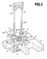
- FIG. 1shows a perspective view of a first preferred exemplary embodiment of a fixing device, with a bow spring pushed in between the bone parts and the second engaging element;
- FIG. 2shows a view similar to FIG. 1 , with the bow spring pulled out and with a schematically represented device for tensioning the two engaging elements with respect to each other;
- FIG. 3shows a view similar to FIG. 1 in the case of a further exemplary embodiment of a fixing device, with an elastic tensioning element held on tensioning rods;
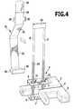
- FIG. 4shows a view similar to FIG. 3 after removal of the elastic tensioning element and before the fitting-on of a bridge for connecting the two tensioning rods;
- FIG. 5shows a view similar to FIG. 1 in the case of a further preferred exemplary embodiment of a fixing device, with an elastically extensible tensioning element surrounding the two engaging elements;
- FIG. 6shows a view similar to FIG. 5 in the case of a further preferred exemplary embodiment, with elastically extensible tensioning elements disposed between the engaging elements, elastically tensioning them with respect to each other;
- FIG. 7shows a view similar to FIG. 5 , with a helical spring surrounding a tensioning rod for elastically tensioning the two engaging elements with respect to each other;
- FIG. 8shows a view similar to FIG. 7 , with a helical spring surrounding a tensioning rod and a support at the free end of the tensioning rod, and
- FIG. 9shows a view similar to FIG. 7 , with spring tongues in the second engaging element for elastically tensioning the two engaging elements with respect to each other.
- the fixing device 1 represented in the drawingserves for connecting two bone parts 2 , 3 lying next to each other, which are only represented very schematically in the drawing. These may be two plate-shaped parts of the cranial bone, two parts of the sternum separated from each other by a saw cut or similar bone parts that are to be fixed in relation to each other while lying side by side, leaving a narrow interspace 4 between the two bone parts 2 , 3 .
- the fixing device 1comprises a rectangular, first engaging plate 5 and a second, likewise rectangular engaging plate 6 . Both engaging plates carry on their longitudinal edges. tooth-shaped projections 7 that point toward the other engaging plate, respectively, protrude substantially transversely from the planar engaging plates, penetrate into the bone material when the engaging plates 5 , 6 are tensioned against the bone parts 2 , 3 and secure the engaging plates 5 , 6 against lateral displacement in relation to the bone parts 2 , 3 .
- the first engaging plate 5is applied to the underside of the bone parts 2 , 3 , to be precise in such a way that it bridges the interspace 4 , and in the same way the second engaging plate 6 is applied to the upper side of the bone parts 2 , 3 .
- the two engaging plates 5 , 6are strongly tensioned with respect to each other in this position, the two bone parts 2 , 3 are fixed with respect to each other.
- the first engaging plate 5carries two tensioning rods 8 , 9 that are disposed in parallel next to each other and extend perpendicularly in relation to the engaging plate, are disposed on the longitudinal center line of the first engaging plate 5 and protrude outward through the interspace 4 when the fixing device 1 is applied, the width of the interspace 4 preferably being determined by the diameter of the tensioning rods 8 , 9 .
- the two tensioning rods 8 , 9are connected to each other at their free end by a bridge 10 , which is held axially in a non-displaceable manner on the tensioning rods 8 , 9 , for example by crimping.
- the tensioning rods 8 , 9pass through the second engaging plate 6 , which for this purpose has two apertures 11 , 12 .
- the edges of these apertures 11 , 12are subdivided into elastic tongues 14 by radial incisions 13 .
- These tongues 14bend back elastically when the second engaging plate 6 is displaced in the direction of the first engaging plate 5 , while at the same time these tongues 14 slide along on circumferential ribs 15 , which are located on the two tensioning rods 8 , 9 . This makes it possible to displace the second engaging plate 6 in the direction of the first engaging plate 5 , but not in the reverse direction, since the tongues 14 prevent a return movement once they have bent back elastically.
- the second engaging plate 6is at first displaced only a little in the direction of the first engaging plate 5 , so that the spacing between the two engaging plates 5 , 6 is much greater than the thickness of the bone parts 2 , 3 to be fixed.
- the fixing device 1is at first positioned on one of the two bone parts 2 or 3 in such a way that the first engaging plate 5 adopts the desired position, and then a bow spring 16 is pushed into the interspace between the upper side of this bone part and the underside of the second engaging plate 6 .
- This bow spring 16consists of an elastically resilient strip material and is bent in a U-shaped manner, so that it has two parallel arms 17 , 18 and a cross-piece 19 , which is bent substantially in the form of a circle and connects these two arms 17 , 18 .
- the lower armis bent back downward at its free end in the form of a slide-on surface 18 a.
- the bow spring 16Along the bow spring 16 , the latter has a central slit 20 , which extends through the entire cross-piece 19 into both arms 17 , 18 and the width of which is at least as great as the diameter of the tensioning rods 8 , 9 .
- the depth to which the spring is pushed inis defined by the end of the slit 20 , one of the two tensioning rods 8 , 9 butting against this end of the slit 20 when the bow spring 16 has been pushed in completely ( FIG. 1 ).
- this elastically compressible bow spring 16tensions the first engaging plate 5 against the underside of the bone part, i.e. the bone part is tensioned between the lower arm 18 of the bow spring 16 and the first engaging plate 5 ( FIG. 1 ).
- the spacing between the two engaging plates 5 , 6can in this case be set in a suitable way by displacement of the second engaging plate 6 in the direction of the first engaging plate 5 , so that as a result the spring force with which the fixing device 1 is held on the bone part can optionally also be set appropriately.
- the other bone part 3can then be pushed laterally into the interspace between the lower arm 18 of the bow spring 16 and the first engaging plate 5 , until the bone part butts against the tensioning rods 8 , 9 .
- the lower arm 18 of the bow spring 16is thereby pressed resiliently upward, so that the bone part can also slide past the protruding projections 7 .
- These projections 7may extend perpendicularly from the two engaging plates 5 , 6 , but it is also possible to incline these projections 7 slightly inward, as can be seen in particular from FIGS. 5 to 9 . This makes it easier for the bone parts to be introduced between the first engaging plate 5 and the bow spring 16 .
- a sloping run-in surface 21may be respectively provided on the side edges of the lower arm 18 of the bow spring 16 , which surface slides along on the bone parts when the bone parts 2 , 3 are pushed toward each other, and thereby resiliently raises the lower arm 18 ( FIGS. 1 and 2 ).
- the fixing device 1is pressed by the bow spring 16 against the bone parts 2 , 3 in such a way that the first engaging plate 5 engages with its projections 7 in the bone parts 2 , 3 , and thereby provides fixing of the fixing device on the bone parts 2 , 3 . It is therefore possible to remove the bow spring 16 again after this fixing, which is effected simply by pulling it out laterally.
- the bow spring 16carries a grip 22 in the form of an obliquely upwardly bent lobe, by which the bow spring 16 can be grasped by hand or by means of an instrument and then pulled out. Although this brings an end to the elastic tensioning force, the fixing device remains in this position, since it is kept in this position by the projections 7 digging into the bone material.
- the tensioning instrument 23engages a bridge 10 with an upper tensioning tool 24 and engages the upper side of the second engaging plate 6 with a lower tensioning tool 25 .
- the two tensioning tools 24 and 25spread apart, the second engaging plate 6 is thereby displaced in the direction of the first engaging plate 5 along the two tensioning rods 8 , 9 , and this leads to a final fixing of the two engaging plates 5 , 6 on the bone parts 2 , 3 ( FIG. 2 ).
- the projecting parts of the tensioning rods 8 , 9can be removed, for example with the aid of a cutting tool, and the fixing device 1 remains in the body.
- the removed upper parts of the tensioning rods 8 , 9 with the bridge 10 and the bow spring 16are removed from the operating area.
- the upper arm 17 of the bow spring 16is convexly curved upward in its middle region between the cross-piece 19 and its end ( FIG. 2 ), this convexity 17 a engaging between the two apertures 11 , 12 , which protrude slightly downward beyond the second engaging plate 6 , when the bow spring 16 has been pushed in completely.
- This engagement of the convexity 17 a between the two downwardly protruding apertures 11 , 12provides fixing of the bow spring 16 against displacement in the direction of the slit 20 , i.e. the bow spring 16 is fixed in the pushed-in state.
- this fixingcan be released by pulling strongly on the grip 22 , as a result of which the convexity 17 a slides up on the downwardly protruding aperture 11 and bends the upper arm 17 elastically downward, so that the bow spring 16 can be pulled out completely from the interspace between the bone part and the upper engaging plate 6 .
- a spring arm 31is releasably held, to be precise with the aid of two clamping members 29 and 30 , which partly grip around the tensioning rods 8 , 9 .
- the spring armconsists of an elastically bendable material in strip form and has a step 26 , which rests on the upper side of the bridge 10 when the spring arm 31 is connected to the fixing device 1 .
- the spring arm 31has two straight portions 32 and 33 , connected to each other at an angle, and, at its lower end, the spring arm 31 goes over into a supporting plate 34 , which runs parallel to the two engaging plates 5 , 6 , is located between the two engaging plates 5 , 6 and has on its longitudinal edge opposite the spring arm 31 an edge region 35 protruding upward at a right angle.
- the supporting plate 34can be moved away from the first engaging plate 5 against the spring force of the spring arm 31 , so that the fixing device 1 can be applied to a bone part in such a way that the latter is tensioned between the supporting plate 34 and the first engaging plate 5 .
- the spring arm 31thereby presses the supporting plate 34 resiliently against the upper side of the bone part and thereby tensions the first engaging plate 5 against the underside of the bone part, it being possible for the tooth-shaped projections 7 to penetrate at least partially into the bone material. In this way, fixing of the fixing device 1 on the bone part is possible, the second engaging plate 6 still remaining at a distance above the bone parts 2 , 3 ( FIG. 3 ).
- the second bone partcan then be pushed laterally in between the supporting plate 34 and the first engaging plate 5 .
- the spring arm 31is removed.
- the clamping elements 29 , 30are bent up.
- the releasing operationis assisted by an upwardly protruding extension 36 in lobe form, by which the spring arm 31 can be grasped.
- the engaging plates 5 , 6can be finally tensioned with respect to each other in a way similar to in the case of the exemplary embodiment of FIG. 2 .
- the first engaging plate 5is tensioned against a bone part by means of a tensioning surface; in the exemplary embodiment of FIGS. 1 and 2 the lower arm 18 forms the tensioning surface, in the exemplary embodiment of FIGS. 3 and 4 the supporting plate 34 forms the tensioning surface.
- FIGS. 5 to 9configurations in which such a tensioning surface is formed by the second engaging plate 6 itself are represented in FIGS. 5 to 9 .
- the fixing devices 1 represented in FIGS. 5 to 9are constructed in a way similar to those of FIGS. 1 to 4 , so parts that correspond to one another have the same designations.
- a single tensioning rod 8is provided, but it would be quite possible also to provide these exemplary embodiments with two tensioning rods in a way similar to that represented in the case of the exemplary embodiments of FIGS. 1 to 4 .
- the two engaging plates 5 , 6are surrounded by an elastic band 37 , which is in the form of a closed loop, is brought past the outside of said plates and in the simplest case is a rubber ring or a comparable elastic component of a material that is tolerated by the body, for example of silicone.
- this band 37it has a widening 38 with an opening 39 , which lies directly over the aperture 11 of the second engaging plate 6 , so that the tensioning rod 8 also passes through this opening 39 .
- the two engaging plates 5 , 6are elastically tensioned with respect to each other by this band 37 , while a stepped widening 40 of the tensioning rod 8 prevents them from coming together completely under the action of the elastic band 37 , this stepped widening 40 directly abutting the first engaging plate 5 and forming a stop for the second engaging plate 6 .
- the second engaging plate 6is freely displaceable on the tensioning rod 8 in both directions, so does not have the radial incisions 13 and the tongue 14 that are provided in the case of the exemplary embodiments of FIGS. 1 to 4 .
- Thismakes it possible to increase the spacing between the two engaging plates 5 , 6 against the action of the elastic band 37 and adapt it to the thickness of the bone parts.
- an arresting disk 41is mounted on the tensioning rod 8 and has a central opening 42 , through which the tensioning rod 8 passes.
- This opening 42is formed in a way similar to the aperture 11 in the case of the exemplary embodiments of FIGS. 1 to 4 , because radial incisions 13 are provided, which incisions subdivide the arresting disk 41 in the edge region of the opening 42 into a number of resilient tongues 14 lying next to one another. In this way, the arresting disk 41 can be displaced from above downward, but because of the circumferential ribs 15 cannot be displaced from below upward, in a way similar to the second engaging plate 6 in the case of the exemplary embodiments of FIGS. 1 to 4 .
- the displacement of the arresting disk 41is performed by a tensioning instrument, which is formed in a way similar to the tensioning instrument 23 in the case of the exemplary embodiment of FIG. 2 ; in this case, the upper tool is then supported on a head-shaped thickening 43 of the tensioning rod 8 .
- the elastic band 37can be removed before the arresting disk 41 is displaced into the final tensioning position; the elastic band can be removed for example simply by cutting it open and pulling it laterally away.
- the two engaging plates 5 , 6are not tensioned with respect to each other by an elastic band surrounding them, but instead by two elastic extensible tensioning elements 44 , 45 , which are respectively fixed by their ends on the two engaging plates 5 , 6 and are disposed in the interspace between the two engaging plates 5 , 6 .
- the arrangementis chosen such that the two tensioning elements 44 , 45 similarly lie in the interspace 4 of the two bone parts 2 , 3 .
- the tensioning elements 44 , 45may be tension springs or rubber-elastic bands.
- tensioning elements 44 , 45can also be removed; in this case, removal is also possible even when the engaging plates 5 , 6 are completely tensioned with respect to each other by the arresting disk 41 .
- the tensioning elements 44 , 45may for example be inserted into the engaging plates 5 , 6 through laterally open slits 46 in the latter and are fixed in the axial direction by a head-shaped thickening 47 . This makes it possible to pull the tensioning elements 44 , 45 laterally out from these slits 46 and in this way release them from the engaging plates 5 , 6 if the tensioning elements 44 , 45 are to be removed.
- the two engaging plates 5 , 6are not tensioned with respect to each other by an elastic band but instead by a helical spring 48 , which concentrically surrounds the tensioning rod 8 and is supported on the one hand on the upper side of the second engaging plate 6 and on the other hand on the underside of the arresting disk 41 , and as a result displaces the second engaging plate 6 elastically toward the first engaging plate 5 .
- this helical spring 48in the final tensioning together of the engaging plates 5 , 6 this helical spring 48 is completely compressed, but it would also be possible to remove this helical spring 48 , for example by the helical spring 48 , which is wound from thin spring wire, being pulled off laterally, so that the spring wire is stretched.
- the helical spring 48 in the case of this exemplary embodimentsurrounds the arresting disk 41 at a spacing and is supported on a stop 49 , which is fitted on the free end of the tensioning rod 8 .
- the stop 49may be held for example in a clamping fit on the tensioning rod 8 or by a thread onto which the stop 49 is screwed, or by a bayonet fastening. This makes it possible to remove the stop 49 after positioning the fixing device 1 on the bone parts and to pull the helical spring 48 off upward, so that the tensioning rod 8 and the arresting disk 41 are exposed in the way that can be seen from FIGS. 5 to 7 .
- the stop 49can be fitted again onto the tensioning rod 8 and then acts in a way similar to the head-shaped thickening 43 as a stop for a tensioning instrument.
- tongue-shaped regionshave been punched out from the second engaging plate 6 by U-shaped cuts, have been bent upward and form the spring tongues 50 , 51 .
- Theseare supported on the arresting disk 41 and thereby tension the engaging plates 5 , 6 resiliently with respect to each other.
- the spacingcan in this case be increased against the spring force of these spring tongues 50 , 51 , so that the fixing device 1 can be pushed laterally onto the bone parts or the bone parts can be pushed in between the engaging plates 5 , 6 .
- the arresting disk 41is displaced downward and thereby at the same time also bends the spring tongues 50 , 51 downward to such an extent that the arresting disk 41 comes to lie on the upper side of the second engaging plate 6 .
- the present inventionprovides advantageous methods and apparatus for the fixing together of adjacent bone parts.
Landscapes
- Health & Medical Sciences (AREA)
- Orthopedic Medicine & Surgery (AREA)
- Surgery (AREA)
- Life Sciences & Earth Sciences (AREA)
- Biomedical Technology (AREA)
- Nuclear Medicine, Radiotherapy & Molecular Imaging (AREA)
- Neurology (AREA)
- Engineering & Computer Science (AREA)
- Heart & Thoracic Surgery (AREA)
- Medical Informatics (AREA)
- Molecular Biology (AREA)
- Animal Behavior & Ethology (AREA)
- General Health & Medical Sciences (AREA)
- Public Health (AREA)
- Veterinary Medicine (AREA)
- Neurosurgery (AREA)
- Surgical Instruments (AREA)
Abstract
Description
Claims (20)
Applications Claiming Priority (2)
| Application Number | Priority Date | Filing Date | Title |
|---|---|---|---|
| DE102006021025 | 2006-04-28 | ||
| DE102006021025ADE102006021025B3 (en) | 2006-04-28 | 2006-04-28 | Surgical fixation device for two bone parts |
Publications (2)
| Publication Number | Publication Date |
|---|---|
| US20070270856A1 US20070270856A1 (en) | 2007-11-22 |
| US7867262B2true US7867262B2 (en) | 2011-01-11 |
Family
ID=38050238
Family Applications (1)
| Application Number | Title | Priority Date | Filing Date |
|---|---|---|---|
| US11/787,113Expired - Fee RelatedUS7867262B2 (en) | 2006-04-28 | 2007-04-12 | Surgical fixing device for two bone parts |
Country Status (5)
| Country | Link |
|---|---|
| US (1) | US7867262B2 (en) |
| EP (1) | EP2012688B1 (en) |
| JP (1) | JP5049339B2 (en) |
| DE (1) | DE102006021025B3 (en) |
| WO (1) | WO2007124807A1 (en) |
Cited By (4)
| Publication number | Priority date | Publication date | Assignee | Title |
|---|---|---|---|---|
| US20110034959A1 (en)* | 2007-12-19 | 2011-02-10 | Sevrain Lionel C | Spring-assisted cranial clamp |
| US20130310885A1 (en)* | 2007-04-06 | 2013-11-21 | Robert J. Schoutens | Securing Device To Secure Fixation Devices To Bone Portions |
| US9468703B2 (en) | 2010-12-13 | 2016-10-18 | Rohit Khanna | Decompressive craniotomy device and methodology |
| US10052143B2 (en) | 2014-04-30 | 2018-08-21 | DePuy Synthes Products, Inc. | Tensioning instrument and related bone fixation systems and methods |
Families Citing this family (65)
| Publication number | Priority date | Publication date | Assignee | Title |
|---|---|---|---|---|
| US8118836B2 (en) | 2004-11-05 | 2012-02-21 | Biomet Sports Medicine, Llc | Method and apparatus for coupling soft tissue to a bone |
| US8303604B2 (en) | 2004-11-05 | 2012-11-06 | Biomet Sports Medicine, Llc | Soft tissue repair device and method |
| US8361113B2 (en) | 2006-02-03 | 2013-01-29 | Biomet Sports Medicine, Llc | Method and apparatus for coupling soft tissue to a bone |
| US7857830B2 (en) | 2006-02-03 | 2010-12-28 | Biomet Sports Medicine, Llc | Soft tissue repair and conduit device |
| US7905904B2 (en) | 2006-02-03 | 2011-03-15 | Biomet Sports Medicine, Llc | Soft tissue repair device and associated methods |
| US8128658B2 (en) | 2004-11-05 | 2012-03-06 | Biomet Sports Medicine, Llc | Method and apparatus for coupling soft tissue to bone |
| US7749250B2 (en) | 2006-02-03 | 2010-07-06 | Biomet Sports Medicine, Llc | Soft tissue repair assembly and associated method |
| US9801708B2 (en) | 2004-11-05 | 2017-10-31 | Biomet Sports Medicine, Llc | Method and apparatus for coupling soft tissue to a bone |
| US8088130B2 (en) | 2006-02-03 | 2012-01-03 | Biomet Sports Medicine, Llc | Method and apparatus for coupling soft tissue to a bone |
| US8137382B2 (en) | 2004-11-05 | 2012-03-20 | Biomet Sports Medicine, Llc | Method and apparatus for coupling anatomical features |
| US7658751B2 (en) | 2006-09-29 | 2010-02-09 | Biomet Sports Medicine, Llc | Method for implanting soft tissue |
| US8298262B2 (en) | 2006-02-03 | 2012-10-30 | Biomet Sports Medicine, Llc | Method for tissue fixation |
| US9017381B2 (en) | 2007-04-10 | 2015-04-28 | Biomet Sports Medicine, Llc | Adjustable knotless loops |
| US8840645B2 (en) | 2004-11-05 | 2014-09-23 | Biomet Sports Medicine, Llc | Method and apparatus for coupling soft tissue to a bone |
| US7909851B2 (en) | 2006-02-03 | 2011-03-22 | Biomet Sports Medicine, Llc | Soft tissue repair device and associated methods |
| US8998949B2 (en) | 2004-11-09 | 2015-04-07 | Biomet Sports Medicine, Llc | Soft tissue conduit device |
| US8771352B2 (en) | 2011-05-17 | 2014-07-08 | Biomet Sports Medicine, Llc | Method and apparatus for tibial fixation of an ACL graft |
| US9078644B2 (en) | 2006-09-29 | 2015-07-14 | Biomet Sports Medicine, Llc | Fracture fixation device |
| US9538998B2 (en) | 2006-02-03 | 2017-01-10 | Biomet Sports Medicine, Llc | Method and apparatus for fracture fixation |
| US9271713B2 (en) | 2006-02-03 | 2016-03-01 | Biomet Sports Medicine, Llc | Method and apparatus for tensioning a suture |
| US8574235B2 (en) | 2006-02-03 | 2013-11-05 | Biomet Sports Medicine, Llc | Method for trochanteric reattachment |
| US10517587B2 (en) | 2006-02-03 | 2019-12-31 | Biomet Sports Medicine, Llc | Method and apparatus for forming a self-locking adjustable loop |
| US8968364B2 (en) | 2006-02-03 | 2015-03-03 | Biomet Sports Medicine, Llc | Method and apparatus for fixation of an ACL graft |
| US8562647B2 (en) | 2006-09-29 | 2013-10-22 | Biomet Sports Medicine, Llc | Method and apparatus for securing soft tissue to bone |
| US11311287B2 (en) | 2006-02-03 | 2022-04-26 | Biomet Sports Medicine, Llc | Method for tissue fixation |
| US8506597B2 (en) | 2011-10-25 | 2013-08-13 | Biomet Sports Medicine, Llc | Method and apparatus for interosseous membrane reconstruction |
| US8652172B2 (en) | 2006-02-03 | 2014-02-18 | Biomet Sports Medicine, Llc | Flexible anchors for tissue fixation |
| US8597327B2 (en) | 2006-02-03 | 2013-12-03 | Biomet Manufacturing, Llc | Method and apparatus for sternal closure |
| US11259792B2 (en) | 2006-02-03 | 2022-03-01 | Biomet Sports Medicine, Llc | Method and apparatus for coupling anatomical features |
| US9468433B2 (en) | 2006-02-03 | 2016-10-18 | Biomet Sports Medicine, Llc | Method and apparatus for forming a self-locking adjustable loop |
| US8251998B2 (en) | 2006-08-16 | 2012-08-28 | Biomet Sports Medicine, Llc | Chondral defect repair |
| US9149267B2 (en) | 2006-02-03 | 2015-10-06 | Biomet Sports Medicine, Llc | Method and apparatus for coupling soft tissue to a bone |
| US8801783B2 (en) | 2006-09-29 | 2014-08-12 | Biomet Sports Medicine, Llc | Prosthetic ligament system for knee joint |
| US8652171B2 (en) | 2006-02-03 | 2014-02-18 | Biomet Sports Medicine, Llc | Method and apparatus for soft tissue fixation |
| US8562645B2 (en) | 2006-09-29 | 2013-10-22 | Biomet Sports Medicine, Llc | Method and apparatus for forming a self-locking adjustable loop |
| US8500818B2 (en) | 2006-09-29 | 2013-08-06 | Biomet Manufacturing, Llc | Knee prosthesis assembly with ligament link |
| US8672969B2 (en) | 2006-09-29 | 2014-03-18 | Biomet Sports Medicine, Llc | Fracture fixation device |
| US11259794B2 (en) | 2006-09-29 | 2022-03-01 | Biomet Sports Medicine, Llc | Method for implanting soft tissue |
| US9918826B2 (en) | 2006-09-29 | 2018-03-20 | Biomet Sports Medicine, Llc | Scaffold for spring ligament repair |
| ES2336059B8 (en) | 2007-08-10 | 2011-08-03 | Neos Surgery, S.L. | A BINDING FRAGMENT FIXING DEVICE. |
| DE102007040695A1 (en)* | 2007-08-29 | 2009-04-23 | Aesculap Ag | Surgical contractor for holding together sections of bone, especially of sternum, has spring-loaded plate which moves along transverse rod to hold first section against second section, which fits against stationary plate |
| EP2949281B1 (en)* | 2008-02-28 | 2016-11-30 | T.A.G. Medical Products Corporation Ltd. | Medical apparatus for attaching a suture to a bone |
| US12419632B2 (en) | 2008-08-22 | 2025-09-23 | Biomet Sports Medicine, Llc | Method and apparatus for coupling anatomical features |
| US12245759B2 (en) | 2008-08-22 | 2025-03-11 | Biomet Sports Medicine, Llc | Method and apparatus for coupling soft tissue to bone |
| US8343227B2 (en) | 2009-05-28 | 2013-01-01 | Biomet Manufacturing Corp. | Knee prosthesis assembly with ligament link |
| US12096928B2 (en) | 2009-05-29 | 2024-09-24 | Biomet Sports Medicine, Llc | Method and apparatus for coupling soft tissue to a bone |
| DE102010000230A1 (en) | 2010-01-27 | 2011-07-28 | Aesculap AG, 78532 | Surgical instruments |
| DE102010000231A1 (en) | 2010-01-27 | 2011-07-28 | Aesculap AG, 78532 | Implant for the mutual support of spinous processes of adjacent vertebral bodies and surgical system |
| EP2637582B1 (en) | 2010-11-12 | 2017-08-23 | Aesculap AG | Spinal fixation system |
| US12329373B2 (en) | 2011-05-02 | 2025-06-17 | Biomet Sports Medicine, Llc | Method and apparatus for soft tissue fixation |
| US9357991B2 (en) | 2011-11-03 | 2016-06-07 | Biomet Sports Medicine, Llc | Method and apparatus for stitching tendons |
| US9314241B2 (en) | 2011-11-10 | 2016-04-19 | Biomet Sports Medicine, Llc | Apparatus for coupling soft tissue to a bone |
| US9381013B2 (en) | 2011-11-10 | 2016-07-05 | Biomet Sports Medicine, Llc | Method for coupling soft tissue to a bone |
| US9370350B2 (en) | 2011-11-10 | 2016-06-21 | Biomet Sports Medicine, Llc | Apparatus for coupling soft tissue to a bone |
| WO2013163101A1 (en)* | 2012-04-23 | 2013-10-31 | Alphatec Spine, Inc. | Interspinous process device and method |
| WO2013167731A1 (en)* | 2012-05-11 | 2013-11-14 | Aesculap Ag | Implant for stabilizing spinous processes |
| US9265530B2 (en) | 2012-12-18 | 2016-02-23 | Neos Surgery S.L. | Apparatus and methods for fixating a cranial bone flap with a cranial bone mass |
| US9757119B2 (en) | 2013-03-08 | 2017-09-12 | Biomet Sports Medicine, Llc | Visual aid for identifying suture limbs arthroscopically |
| US9918827B2 (en) | 2013-03-14 | 2018-03-20 | Biomet Sports Medicine, Llc | Scaffold for spring ligament repair |
| US10136886B2 (en) | 2013-12-20 | 2018-11-27 | Biomet Sports Medicine, Llc | Knotless soft tissue devices and techniques |
| US9615822B2 (en) | 2014-05-30 | 2017-04-11 | Biomet Sports Medicine, Llc | Insertion tools and method for soft anchor |
| US9700291B2 (en) | 2014-06-03 | 2017-07-11 | Biomet Sports Medicine, Llc | Capsule retractor |
| US10039543B2 (en) | 2014-08-22 | 2018-08-07 | Biomet Sports Medicine, Llc | Non-sliding soft anchor |
| US9955980B2 (en) | 2015-02-24 | 2018-05-01 | Biomet Sports Medicine, Llc | Anatomic soft tissue repair |
| US9974534B2 (en) | 2015-03-31 | 2018-05-22 | Biomet Sports Medicine, Llc | Suture anchor with soft anchor of electrospun fibers |
Citations (25)
| Publication number | Priority date | Publication date | Assignee | Title |
|---|---|---|---|---|
| EP0014823A1 (en) | 1979-02-06 | 1980-09-03 | HOWMEDICA INTERNATIONAL, INC. Zweigniederlassung Kiel | Implant for the fixation of rib fractures |
| US4279248A (en) | 1979-07-20 | 1981-07-21 | Shlomo Gabbay | Sternum closure device and procedure for using same |
| EP0209602A1 (en) | 1985-02-04 | 1987-01-28 | Jürgen Peter Erich MESCHKE | Rappel line clamp and harness |
| US4670938A (en) | 1984-05-14 | 1987-06-09 | Fowlston Kenneth B | One piece flexible hinge having engaging ridges and a rib |
| US4802477A (en) | 1987-05-07 | 1989-02-07 | Shlomo Gabbay | Sternum closure device |
| US5549620A (en) | 1994-12-06 | 1996-08-27 | Bremer; Paul | Brain surgery with craniotomy pin |
| US5620452A (en) | 1994-12-22 | 1997-04-15 | Yoon; Inbae | Surgical clip with ductile tissue penetrating members |
| US5722976A (en) | 1993-08-27 | 1998-03-03 | Brown; Robin Peter | Apparatus and method for surgically securing bone parts |
| US5729867A (en) | 1996-11-05 | 1998-03-24 | Carmichael; Carl C. | Flexible and detachable web hinge for display panels capable of orienting one panel relative to another through 360 degrees |
| DE19634696C1 (en)* | 1996-08-28 | 1998-04-23 | Aesculap Ag & Co Kg | Surgical device for alignment and temporary fixation of cap segment removed from skull capsule to remaining skull cap |
| US5800436A (en) | 1996-02-03 | 1998-09-01 | Lerch; Karl-Dieter | Device for postoperative fixation back into the cranium of a plug of bone removed therefrom during a surgical operation |
| DE29919090U1 (en) | 1999-10-30 | 2000-01-13 | Aesculap AG & Co. KG, 78532 Tuttlingen | Surgical connecting element for fixing adjacent bone plates |
| US6022351A (en) | 1999-02-23 | 2000-02-08 | Bremer; Paul W. | Skull closure device and procedure |
| US6045552A (en) | 1998-03-18 | 2000-04-04 | St. Francis Medical Technologies, Inc. | Spine fixation plate system |
| JP2003220070A (en) | 2002-01-31 | 2003-08-05 | Kanai Hiroaki | Fixation device for osteosynthesis |
| DE20315612U1 (en) | 2003-10-08 | 2003-12-11 | Aesculap Ag & Co. Kg | Surgical connecting element, for fixing adjacent bone plates, comprises two contact elements, coupling element, and locking element |
| WO2004006783A1 (en) | 2002-07-12 | 2004-01-22 | Shlomo Gabbay | Sternum closure apparatus and method for helping maintain a space between parts of the sternum |
| WO2004016205A2 (en) | 2002-08-15 | 2004-02-26 | Coppes Justin K | Intervertebral disc implant |
| WO2004107998A1 (en)* | 2003-06-04 | 2004-12-16 | Aesculap Ag & Co. Kg | Sternum closure |
| US20050065521A1 (en) | 2002-02-22 | 2005-03-24 | Steger Shon D. | Method and apparatus for bone fracture fixation |
| US20050278027A1 (en) | 2004-06-11 | 2005-12-15 | Hyde Edward R Jr | Annulus fibrosus stent |
| WO2006002744A1 (en) | 2004-07-05 | 2006-01-12 | Neos Surgery, S.L. | Device for fastening post-craniotomy bone flaps |
| DE102004038823B3 (en) | 2004-08-04 | 2006-03-30 | Aesculap Ag & Co. Kg | Implant for fixing adjacent bone plates |
| US20070038218A1 (en) | 2005-08-12 | 2007-02-15 | Mark Grevious | Sternal closure device |
| US7361178B2 (en)* | 2000-07-27 | 2008-04-22 | Synthes (U.S.A.) | Cranial flap clamp and instrument for use therewith |
- 2006
- 2006-04-28DEDE102006021025Apatent/DE102006021025B3/ennot_activeExpired - Fee Related
- 2007
- 2007-03-02JPJP2009504582Apatent/JP5049339B2/ennot_activeExpired - Fee Related
- 2007-03-02WOPCT/EP2007/001791patent/WO2007124807A1/enactiveApplication Filing
- 2007-03-02EPEP07703578.0Apatent/EP2012688B1/ennot_activeNot-in-force
- 2007-04-12USUS11/787,113patent/US7867262B2/ennot_activeExpired - Fee Related
Patent Citations (28)
| Publication number | Priority date | Publication date | Assignee | Title |
|---|---|---|---|---|
| EP0014823A1 (en) | 1979-02-06 | 1980-09-03 | HOWMEDICA INTERNATIONAL, INC. Zweigniederlassung Kiel | Implant for the fixation of rib fractures |
| US4279248A (en) | 1979-07-20 | 1981-07-21 | Shlomo Gabbay | Sternum closure device and procedure for using same |
| US4670938A (en) | 1984-05-14 | 1987-06-09 | Fowlston Kenneth B | One piece flexible hinge having engaging ridges and a rib |
| EP0209602A1 (en) | 1985-02-04 | 1987-01-28 | Jürgen Peter Erich MESCHKE | Rappel line clamp and harness |
| US4802477A (en) | 1987-05-07 | 1989-02-07 | Shlomo Gabbay | Sternum closure device |
| US5722976A (en) | 1993-08-27 | 1998-03-03 | Brown; Robin Peter | Apparatus and method for surgically securing bone parts |
| US5549620A (en) | 1994-12-06 | 1996-08-27 | Bremer; Paul | Brain surgery with craniotomy pin |
| US5620452A (en) | 1994-12-22 | 1997-04-15 | Yoon; Inbae | Surgical clip with ductile tissue penetrating members |
| US5800436A (en) | 1996-02-03 | 1998-09-01 | Lerch; Karl-Dieter | Device for postoperative fixation back into the cranium of a plug of bone removed therefrom during a surgical operation |
| DE19634696C1 (en)* | 1996-08-28 | 1998-04-23 | Aesculap Ag & Co Kg | Surgical device for alignment and temporary fixation of cap segment removed from skull capsule to remaining skull cap |
| US5729867A (en) | 1996-11-05 | 1998-03-24 | Carmichael; Carl C. | Flexible and detachable web hinge for display panels capable of orienting one panel relative to another through 360 degrees |
| US6045552A (en) | 1998-03-18 | 2000-04-04 | St. Francis Medical Technologies, Inc. | Spine fixation plate system |
| US6022351A (en) | 1999-02-23 | 2000-02-08 | Bremer; Paul W. | Skull closure device and procedure |
| DE29919090U1 (en) | 1999-10-30 | 2000-01-13 | Aesculap AG & Co. KG, 78532 Tuttlingen | Surgical connecting element for fixing adjacent bone plates |
| US7361178B2 (en)* | 2000-07-27 | 2008-04-22 | Synthes (U.S.A.) | Cranial flap clamp and instrument for use therewith |
| JP2003220070A (en) | 2002-01-31 | 2003-08-05 | Kanai Hiroaki | Fixation device for osteosynthesis |
| US20050065521A1 (en) | 2002-02-22 | 2005-03-24 | Steger Shon D. | Method and apparatus for bone fracture fixation |
| WO2004006783A1 (en) | 2002-07-12 | 2004-01-22 | Shlomo Gabbay | Sternum closure apparatus and method for helping maintain a space between parts of the sternum |
| WO2004016205A2 (en) | 2002-08-15 | 2004-02-26 | Coppes Justin K | Intervertebral disc implant |
| WO2004107998A1 (en)* | 2003-06-04 | 2004-12-16 | Aesculap Ag & Co. Kg | Sternum closure |
| DE10326690A1 (en) | 2003-06-04 | 2005-01-05 | Aesculap Ag & Co. Kg | Sternum closure |
| US20060122611A1 (en) | 2003-06-04 | 2006-06-08 | Aesculap Ag & Co. Kg | Sternum closure device |
| DE20315612U1 (en) | 2003-10-08 | 2003-12-11 | Aesculap Ag & Co. Kg | Surgical connecting element, for fixing adjacent bone plates, comprises two contact elements, coupling element, and locking element |
| US20050278027A1 (en) | 2004-06-11 | 2005-12-15 | Hyde Edward R Jr | Annulus fibrosus stent |
| WO2006002744A1 (en) | 2004-07-05 | 2006-01-12 | Neos Surgery, S.L. | Device for fastening post-craniotomy bone flaps |
| DE102004038823B3 (en) | 2004-08-04 | 2006-03-30 | Aesculap Ag & Co. Kg | Implant for fixing adjacent bone plates |
| US20070250059A1 (en) | 2004-08-04 | 2007-10-25 | Dieter Weisshaupt | Implant for securing neighbouring bone plates |
| US20070038218A1 (en) | 2005-08-12 | 2007-02-15 | Mark Grevious | Sternal closure device |
Non-Patent Citations (1)
| Title |
|---|
| Patent Abstracts of Japan, vol. 2003, No. 06, "Sacrum Fixing Device", Publication No. 2003038504, Publication Date Feb. 12, 2003. |
Cited By (7)
| Publication number | Priority date | Publication date | Assignee | Title |
|---|---|---|---|---|
| US20130310885A1 (en)* | 2007-04-06 | 2013-11-21 | Robert J. Schoutens | Securing Device To Secure Fixation Devices To Bone Portions |
| US9351765B2 (en)* | 2007-04-06 | 2016-05-31 | DePuy Synthes Products, Inc. | Securing device to secure fixation devices to bone portions |
| US20110034959A1 (en)* | 2007-12-19 | 2011-02-10 | Sevrain Lionel C | Spring-assisted cranial clamp |
| US8992588B2 (en)* | 2007-12-19 | 2015-03-31 | Lers Surgical, Llc | Spring-assisted cranial clamp |
| US9468703B2 (en) | 2010-12-13 | 2016-10-18 | Rohit Khanna | Decompressive craniotomy device and methodology |
| US9950098B2 (en) | 2010-12-13 | 2018-04-24 | Rohit Khanna | Device and method for performing a decompressive craniotomy |
| US10052143B2 (en) | 2014-04-30 | 2018-08-21 | DePuy Synthes Products, Inc. | Tensioning instrument and related bone fixation systems and methods |
Also Published As
| Publication number | Publication date |
|---|---|
| JP2009533107A (en) | 2009-09-17 |
| EP2012688A1 (en) | 2009-01-14 |
| DE102006021025B3 (en) | 2008-01-03 |
| US20070270856A1 (en) | 2007-11-22 |
| JP5049339B2 (en) | 2012-10-17 |
| EP2012688B1 (en) | 2015-08-26 |
| WO2007124807A1 (en) | 2007-11-08 |
Similar Documents
| Publication | Publication Date | Title |
|---|---|---|
| US7867262B2 (en) | Surgical fixing device for two bone parts | |
| JP4234585B2 (en) | A kit comprising a medical fixator and a device for placing the fixator | |
| KR100720210B1 (en) | Intervertebral insert | |
| US8221464B2 (en) | Device for clamping two portions of a braid and an intervertebral implant comprising a spacer, a braid, and such a clamping device | |
| CN107405142B (en) | Suture fixing device | |
| US7238188B2 (en) | Implant for fixing bone plates | |
| US20060122611A1 (en) | Sternum closure device | |
| US8133227B2 (en) | Sternum closure device | |
| US8172859B2 (en) | Clipping device | |
| US8523880B2 (en) | Medical clip and apparatus for the application of such a clip | |
| US20080009900A1 (en) | Surgical grasping device | |
| US9149297B2 (en) | Flexible cranial clamp and method of anchoring to cranium | |
| EP0592959A2 (en) | Suture clip | |
| US9408600B2 (en) | Releasable suture clamp and suture anchor assembly including same | |
| US20120123447A1 (en) | Device for tensioning flexible material | |
| JP2004008805A (en) | Device and method for fixing skull and osteocortical flap | |
| US20060282102A1 (en) | Method and apparatus for holding suture ends to facilitate tying of knots | |
| WO1997041780A1 (en) | Disposable loading unit for a vascular suturing instrument | |
| EP0510084A4 (en) | Suture knotting instrument | |
| CN107028650A (en) | Bone fracture fixation clamp | |
| US10123832B2 (en) | Surgical forceps system | |
| US7674280B2 (en) | Implant for fixing adjacent bone plates | |
| US10206723B2 (en) | Rod inserter and insertion tube | |
| JP2025061964A (en) | Method and apparatus for supporting a U-shaped portion of an elongated flexible element against body tissue - Patents.com | |
| US20130110181A1 (en) | Cranial fixation device |
Legal Events
| Date | Code | Title | Description |
|---|---|---|---|
| AS | Assignment | Owner name:AESCULAP AG & CO. KG, GERMANY Free format text:ASSIGNMENT OF ASSIGNORS INTEREST;ASSIGNORS:MORALES, PEDRO;WEISSHAUPT, DIETER;DWORSCHAK, MANFRED;AND OTHERS;REEL/FRAME:019519/0200;SIGNING DATES FROM 20070523 TO 20070529 Owner name:AESCULAP AG & CO. KG, GERMANY Free format text:ASSIGNMENT OF ASSIGNORS INTEREST;ASSIGNORS:MORALES, PEDRO;WEISSHAUPT, DIETER;DWORSCHAK, MANFRED;AND OTHERS;SIGNING DATES FROM 20070523 TO 20070529;REEL/FRAME:019519/0200 | |
| AS | Assignment | Owner name:AESCULAP AG, GERMANY Free format text:CHANGE OF NAME;ASSIGNOR:AESCULAP AG & CO. KG;REEL/FRAME:021731/0524 Effective date:20080506 Owner name:AESCULAP AG,GERMANY Free format text:CHANGE OF NAME;ASSIGNOR:AESCULAP AG & CO. KG;REEL/FRAME:021731/0524 Effective date:20080506 | |
| FPAY | Fee payment | Year of fee payment:4 | |
| FEPP | Fee payment procedure | Free format text:MAINTENANCE FEE REMINDER MAILED (ORIGINAL EVENT CODE: REM.); ENTITY STATUS OF PATENT OWNER: LARGE ENTITY | |
| LAPS | Lapse for failure to pay maintenance fees | Free format text:PATENT EXPIRED FOR FAILURE TO PAY MAINTENANCE FEES (ORIGINAL EVENT CODE: EXP.); ENTITY STATUS OF PATENT OWNER: LARGE ENTITY | |
| STCH | Information on status: patent discontinuation | Free format text:PATENT EXPIRED DUE TO NONPAYMENT OF MAINTENANCE FEES UNDER 37 CFR 1.362 | |
| FP | Lapsed due to failure to pay maintenance fee | Effective date:20190111 |