US7867255B2 - Spinal rod connector system and method for a bone anchor - Google Patents
Spinal rod connector system and method for a bone anchorDownload PDFInfo
- Publication number
- US7867255B2 US7867255B2US11/399,927US39992706AUS7867255B2US 7867255 B2US7867255 B2US 7867255B2US 39992706 AUS39992706 AUS 39992706AUS 7867255 B2US7867255 B2US 7867255B2
- Authority
- US
- United States
- Prior art keywords
- spinal rod
- receiver
- connector
- receptacle
- mounting
- Prior art date
- Legal status (The legal status is an assumption and is not a legal conclusion. Google has not performed a legal analysis and makes no representation as to the accuracy of the status listed.)
- Active, expires
Links
- 0CC1=*CCC1Chemical compoundCC1=*CCC10.000description1
Images


Classifications
- A—HUMAN NECESSITIES
- A61—MEDICAL OR VETERINARY SCIENCE; HYGIENE
- A61B—DIAGNOSIS; SURGERY; IDENTIFICATION
- A61B17/00—Surgical instruments, devices or methods
- A61B17/56—Surgical instruments or methods for treatment of bones or joints; Devices specially adapted therefor
- A61B17/58—Surgical instruments or methods for treatment of bones or joints; Devices specially adapted therefor for osteosynthesis, e.g. bone plates, screws or setting implements
- A61B17/68—Internal fixation devices, including fasteners and spinal fixators, even if a part thereof projects from the skin
- A61B17/70—Spinal positioners or stabilisers, e.g. stabilisers comprising fluid filler in an implant
- A61B17/7049—Connectors, not bearing on the vertebrae, for linking longitudinal elements together
- A61B17/705—Connectors, not bearing on the vertebrae, for linking longitudinal elements together for linking adjacent ends of longitudinal elements
- A—HUMAN NECESSITIES
- A61—MEDICAL OR VETERINARY SCIENCE; HYGIENE
- A61B—DIAGNOSIS; SURGERY; IDENTIFICATION
- A61B17/00—Surgical instruments, devices or methods
- A61B17/56—Surgical instruments or methods for treatment of bones or joints; Devices specially adapted therefor
- A61B17/58—Surgical instruments or methods for treatment of bones or joints; Devices specially adapted therefor for osteosynthesis, e.g. bone plates, screws or setting implements
- A61B17/68—Internal fixation devices, including fasteners and spinal fixators, even if a part thereof projects from the skin
- A61B17/84—Fasteners therefor or fasteners being internal fixation devices
- A61B17/86—Pins or screws or threaded wires; nuts therefor
- A—HUMAN NECESSITIES
- A61—MEDICAL OR VETERINARY SCIENCE; HYGIENE
- A61B—DIAGNOSIS; SURGERY; IDENTIFICATION
- A61B17/00—Surgical instruments, devices or methods
- A61B17/56—Surgical instruments or methods for treatment of bones or joints; Devices specially adapted therefor
- A61B17/58—Surgical instruments or methods for treatment of bones or joints; Devices specially adapted therefor for osteosynthesis, e.g. bone plates, screws or setting implements
- A61B17/68—Internal fixation devices, including fasteners and spinal fixators, even if a part thereof projects from the skin
- A61B17/70—Spinal positioners or stabilisers, e.g. stabilisers comprising fluid filler in an implant
- A61B17/7001—Screws or hooks combined with longitudinal elements which do not contact vertebrae
- A61B17/7032—Screws or hooks with U-shaped head or back through which longitudinal rods pass
- A—HUMAN NECESSITIES
- A61—MEDICAL OR VETERINARY SCIENCE; HYGIENE
- A61B—DIAGNOSIS; SURGERY; IDENTIFICATION
- A61B17/00—Surgical instruments, devices or methods
- A61B17/56—Surgical instruments or methods for treatment of bones or joints; Devices specially adapted therefor
- A61B17/58—Surgical instruments or methods for treatment of bones or joints; Devices specially adapted therefor for osteosynthesis, e.g. bone plates, screws or setting implements
- A61B17/68—Internal fixation devices, including fasteners and spinal fixators, even if a part thereof projects from the skin
- A61B17/70—Spinal positioners or stabilisers, e.g. stabilisers comprising fluid filler in an implant
- A61B17/7001—Screws or hooks combined with longitudinal elements which do not contact vertebrae
- A61B17/7041—Screws or hooks combined with longitudinal elements which do not contact vertebrae with single longitudinal rod offset laterally from single row of screws or hooks
Definitions
- the spineis subject to various pathologies that compromise its load bearing and support capabilities.
- Such pathologies of the spineinclude, for example, degenerative diseases, the effects of tumors and, of course, fractures and dislocations attributable to physical trauma.
- spinal motion segmentswhich include two or more adjacent vertebrae and the disc tissue or disc space therebetween
- artificial discs, fusion implants, or other interbody devicescan be placed into the disc space after disc material removal.
- External stabilization of spinal segments alone or in combination with interbody devicesalso provides advantages. Elongated rigid plates, rods and other external stabilization devices have been helpful in the stabilization and fixation of a spinal motion segment, in correcting abnormal curvatures and alignments of the spinal column, and for treatment of other conditions.
- a spinal rod systemincludes a mounting anchor including a first portion for engaging a bony structure and a receiver defining a first receptacle.
- a first elongated spinal rodis positioned in the receptacle of the mounting anchor.
- a connectorincludes a body extending along a longitudinal axis that is oriented transversely to the first spinal rod.
- the bodyincludes a mounting portion and a receiving portion along the longitudinal axis.
- the mounting portionis positioned about the receiver and engaged thereto with an engaging member.
- the receiving portionis positioned adjacent the receiver of the mounting anchor and defines a second receptacle.
- a second spinal rodcan be engaged in the second receptacle of the receiving portion of the connector and extends from the receiving portion in generally parallel relation with the first spinal rod.
- a spinal rod systemincludes a mounting anchor including a first portion for engaging a bony structure and a receiver defining a first receptacle.
- a first elongated spinal rodis positioned in the receiver of the mounting anchor.
- a connectorincludes a body extending along a longitudinal axis and oriented transversely to the first spinal rod.
- the bodyincludes a mounting portion and a receiving portion along the longitudinal axis.
- the mounting portionis positioned about the receiver and is clampingly engaged between the first spinal rod and an engaging member engaged to the receiver of the mounting anchor.
- the receiving portion of the connector bodyalso defines a second receptacle adjacent the mounting portion.
- a second spinal rodcan be engaged to the receiving portion of the connector in the second receptacle so that the second spinal rod extends from the receiving portion in generally parallel relation with the first spinal rod.
- a method for assembling a spinal rod systemcomprises: positioning a first spinal rod into a first receptacle defined by a receiver of a mounting anchor; positioning a mounting portion of a connector body about the receiver of the mounting anchor; securing an engaging member to the receiver of the mounting anchor with a flange of the engaging member in contact with the connector body and the connector body in contact with the first spinal rod outside the first receptacle; advancing the engaging member into the receiver thereby advancing the connector body and spinal rod in contact therewith until the spinal rod is seated against the receiver of the mounting anchor; and engaging a second spinal rod to the connector body.
- a spinal rod systemincludes a mounting anchor including a first portion for engaging a bony structure and a receiver defining a first receptacle.
- a first elongated spinal rodis positioned in the receptacle of the mounting anchor.
- a connectorincludes a body extending along a longitudinal axis that is oriented along the first spinal rod.
- the bodyincludes a mounting portion and a receiving portion along the longitudinal axis.
- the mounting portionis positioned about the receiver and engaged thereto with an engaging member.
- the receiving portionis positioned adjacent the receiver of the mounting anchor and defines a second receptacle.
- a second spinal rodcan be engaged in the second receptacle of the receiving portion of the connector and extends from the receiving portion in generally end-to-end and axial alignment with the first spinal rod.
- a spinal rod systemincludes a mounting anchor including a first portion for engaging a bony structure and a receiver defining a first receptacle.
- a first elongated spinal rodis positioned in the receiver of the mounting anchor.
- a connectorincludes a body extending along a longitudinal axis that extends in the same direction as and way from an end of the spinal rod in the receiver of the mounting anchor.
- the bodyincludes a mounting portion and a receiving portion along the longitudinal axis.
- the mounting portionis positioned about the receiver and is clampingly engaged between the first spinal rod and an engaging member engaged to the receiver of the mounting anchor.
- the receiving portion of the connector bodyalso defines a second receptacle adjacent the mounting portion.
- a second spinal rodcan be engaged to the receiving portion of the connector in the second receptacle so that the second spinal rod extends from the receiving portion in a generally aligned and end-to-end relation with the first spinal rod.
- FIG. 1is an elevation view of a spinal column segment shown diagrammatically and one embodiment of a stabilization system employing a connector to connect two rods to an anchor.
- FIG. 2is an elevation view of one embodiment of an anchor engageable with a vertebral body of the spinal column segment.
- FIG. 3is a plan view of the anchor of FIG. 2 with a spinal rod positioned in the anchor.
- FIG. 4is a plan view of the connector of FIG. 1 .
- FIG. 5is a section view of the connector through line 5 - 5 of FIG. 4 and further showing a pair of rods positioned relative to the connector.
- FIG. 6is a section view of a first engaging member for coupling the connector to the anchor.
- FIG. 7is a section view of a second engaging member for coupling a rod to the connector.
- FIG. 8is a plan view of another embodiment connector.
- FIG. 9is a section view of the connector through line 9 - 9 of FIG. 8 and further showing a pair of rods positioned relative to the connector.
- FIG. 10is a section view of another embodiment connector and pair of spinal rods positioned relative thereto.
- FIG. 11is an elevation view of a spinal column segment shown diagrammatically and another embodiment of a stabilization system employing another embodiment connector to connect two rods to an anchor.
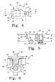
- FIG. 12is a plan view of the connector of FIG. 11 .
- FIG. 13is a section view of the connector along line 13 - 13 of FIG. 12 .
- FIG. 14is a plan view of another embodiment connector.
- FIG. 1there is shown a spinal rod system 10 including a first rod 12 and a second rod 22 .
- First rod 12 and second rod 22are releasably coupled to one another with connector 30 at a mounting anchor 28 with rods 12 , 22 in laterally offset and axially extending relation to one another when positioned along the spinal column.
- Rods 12 , 22provide a construct between the respective first and second vertebrae V 1 and V 2 and the respective second and third vertebrae V 2 and V 3 to provide a desired stabilization effect.
- First rod 12can be secured to at least one vertebra V 1 with at least one first anchor 14
- second rod 22can be secured to at least one third vertebra V 3 with at least one third anchor 24 .
- Rods 12 , 22are secured to second, mounting anchor 28 engaged to vertebra V 2 to provide a spinal rod system 10 along vertebrae V 1 , V 2 , V 3 .
- the length of the construct between anchors 14 and 28 and anchors 24 and 28can be decreased or increased by adjusting the axial positioning of one or more of the rods 12 , 22 in the respective mounting anchor 28 and/or rod connector 30 .
- Such adjustmentmay be desirable, for example, to provide an optimal fit during surgery, to allow rods of shorter length to be assembled in a single system, to allow rods of varying properties to be employed in the same system, and/or to adjust the length of the construct as a result of growth or other changes in the patient anatomy after the initial implantation procedure.
- system 10can be adapted to extend along a single vertebral level, two vertebral levels as shown, or along three or more vertebral levels.
- System 10can employ multiple mounting anchors and connectors along with multiple other anchors to secure two or more rods along the spinal column.
- Connector 30includes a connector body 32 releasably engageable to mounting anchor 28 and second rod 22 .
- connector body 32is positionable in contact with first rod 12 in mounting anchor 28 to secure first rod 12 to mounting anchor 28 .
- Body 32 of connector 30also includes a receptacle 44 for receiving second rod 22 therein.
- Connector 30is configured to secure rods 12 , 22 with rod 12 along rod axis 13 and rod 22 along rod axis 23 .
- Axes 13 , 23can be generally parallel and offset from one another while minimizing the footprint or intrusiveness of the connector into the tissue surrounding the rod system and allowing the length of the rod construct for positioning and/or attachment along the spinal column to be readily adjustable.
- the rods 12 , 22can extend along their respective axes 13 , 23 in opposite directions from rod connector 30 for positioning along one or more spinal motion segments of the spinal column to provide stabilization.
- one embodiment for mounting anchor 28is a bone screw with a tulip or U-shaped receiver 90 to receive rod 12 therethrough.
- Receiver 90includes a pair of arms 92 , 93 defining internal threads there along to threadingly engage an engaging member, such as engaging member 60 shown in FIG. 6 .
- Arms 92 , 93define a receptacle 94 therebetween through which one of the rods 12 , 22 can extend, such as shown with respect to rod 12 .
- a bone engaging portion 96extends distally from receiver 90 and can include an elongated shaft-like structure with external threads configured to threadingly engage bony tissue of a vertebral body.
- bone engaging portion 96Other forms for bone engaging portion 96 are also contemplated, including hooks, staples, pins, spikes, wires, cables, sutures or other structure engageable to a vertebral body.
- anchor 28is shown with bone engaging portion 96 fixed relative to receiver 90 .
- Other forms contemplate bone engaging portion 96is pivotal relative to receiver 90 in any one or combination of uni-planar, multi-axial, cone-shaped or otherwise configured pivot paths and orientations.
- bone engaging portion 96can include a head pivotally captured in receiver 90 .
- Anchors 14 and 24can be configured similarly to anchor 28 , or may include any suitable configuration for securing a spinal rod along the spinal column.
- Connector body 32includes a receiving portion 38 for receiving rod 22 therein and a mounting portion 40 alongside receiving portion 38 for positioning about mounting anchor 28 .
- Connector body 32extends along a longitudinal axis 34 that is transversely oriented to rods 12 , 22 when rods 12 , 22 are engaged to connector body 32 .
- the width of connector body 32 transverse to longitudinal axis 34can be less than, the same as, or greater than the length along longitudinal axis 34 .
- the width transverse to longitudinal axis 34can vary along its length.
- Mounting portion 40includes a length and width along and transverse to longitudinal axis 34 to accommodate receiver 90 of anchor 38 in window 50 .
- Receiving portion 38includes a length along axis 34 sufficient to form receptacle 44 for receiving rod 22 therein along a rod axis 23 .
- Receiving portion 38also includes a bore 42 for receiving an engaging member, such as engaging member 80 shown in FIG. 7 , to secure rod 22 in position in receptacle 44 .
- engaging member 80is a set screw type member with a threaded body 82 threadingly engageable to internal threads along bore 42 .
- a tool engaging portion 84may be provided for engagement with a driving tool.
- Tool engaging portion 84may be in the form of a proximally extending member as shown integrally formed with body 82 , or may be in the form of an internal tool recess in body 82 .
- Tool engaging portion 84can be severable on application of a threshold torque to engaging member 80 when body 82 is positioned in contact with rod 22 in receptacle 44 .
- Tool engaging portion 84can also be fixed and non-removable from body 82 .
- Receiving portion 38can include a depth d 1 from a proximal or upper surface 48 of connector body 32 that positions the centerline of rod 22 in alignment distally and proximally with the depth d 2 of the centerline of rod 12 below proximal surface 48 .
- Other embodimentscontemplate that depth d 1 and depth d 2 differ from one another to accommodate, for example, changes in the anatomy of the patient.
- Mounting portion 40 of connector body 32includes a central window 50 to receive receiver 90 of anchor 28 therein, as shown in FIG. 6 .
- Wall 52extends around window 50 and is shaped like the outer perimeter of anchor 28 so that receiver 90 is received in close, form-fitting engagement therewith.
- At least one contact member 54extends distally from or is formed with wall 52 and is positioned in contact with rod 12 outside receptacle 94 .
- Contact member 54includes a distal contact surface 56 that can be concavely curved to fit around a portion of the convexly curved perimeter of rod 12 . It is contemplated that a contact member 54 can be provided on each side of anchor 28 to contact rod 12 outside receptacle 94 .
- the distal contact surfacecan include any suitable configuration, including configurations that conform to or extend around rods with non-circular outer perimeters.
- Engaging member 60is engageable to anchor 28 in receiver 90 with a threaded body portion 62 .
- Body portion 62includes at least one flange 64 extending outwardly therefrom that can contact connector body 32 along proximal surface 48 to force contact member 54 into contact with rod 12 .
- engaging member 60is threadingly advanced into receiver 90
- rod 12is seated against receiver 90 by contact members 54 pressing thereagainst, limiting or preventing further rotation of engaging member 60 .
- connector body 32is clamped between flange 64 and rod 12 .
- engaging member 60is a set screw type member with threaded body 62 threadingly engageable to internal threads along arms 92 , 93 of receiver 90 .
- a tool engaging portion 66may be provided for engagement with a driving tool.
- Tool engaging portion 66may be in the form of a proximally extending member as shown integrally formed with flange 64 , or may be in the form of an internal tool recess.
- Tool engaging portion 66can be severable on application of a threshold torque to engaging member 60 when rod 12 is seated in receiver 90 of anchor 28 .
- Tool engaging portion 66can also be fixed and non-removable from body 62 .
- flange 64is rotatably captured between tool engaging portion 66 and body 62 so that its relative orientation with connector body 32 is maintained as engaging member 60 is engaged to anchor 28 .
- Flange 64can include an outer perimeter that is rectangular, square, circular or any other suitable shape to contact the proximal surface 48 of connector body 32 .
- FIGS. 8-9show connector 130 with a connector body 132 having a receiving portion 138 and a mounting portion 140 .
- Mounting portion 140can be configured like mounting portion 40 discussed above.
- receiving portion 138includes an open configuration where a pair of arms 142 , 143 define a receptacle 144 therebetween for receiving engaging member 80 .
- Rod 22can be positioned between arms 142 , 143 in a side-loading fashion, i.e. from the side of rod 22 , and seated in the bottom of receptacle 144 .
- Engaging member 80can be threadingly engaged to arms 142 , 143 into contact with rod 22 to firmly seat and secure rod 22 against receiving portion 138 .
- receiving portion 38was shown with a closed type configuration around bore 42 , and thus rod 22 is loaded in an endwise fashion, or end-loaded, into and through receptacle 44 .
- FIG. 10shows another embodiment connector 230 having a connector body 232 with a receiving portion 238 and a mounting portion 240 .
- Mounting portion 240can be configured like mounting portion 40 discussed above and positioned about mounting anchor 28 and engaged to rod 12 with engaging member 60 .
- Receiving portion 138includes a bore 242 that extends along an oblique bore axis 243 from receptacle 244 .
- Bore axis 243is obliquely oriented to an engaging axis 53 along which engaging member 60 engages mounting anchor 28 when viewed in section along longitudinal axis 234 as shown in FIG. 10 .
- bore axis 243is obliquely oriented to longitudinal axis 234 of body 232 when viewed in section along longitudinal axis 234 as shown in FIG. 10 .
- axis 243extends from rod 22 through a side of connector body 32 that is remote from rod 12 .
- bore 242 and thus bore axis 243extend from receptacle 244 toward window 250 through upper proximal surface 248 of connector body 232 .
- Rods 12 , 22can be of the same size, shape and material properties, or more have one or more of these characteristics that differ from one another.
- Connector 30allows rods of differing characteristics to be secured to one another in laterally offset and axially extending relation for positioning along multiple levels of the spinal column and provide a rod system that is adapted for the anatomy, surgical condition, or surgical procedure.
- the characteristicsinclude differing cross-sectional dimensions of the rods 12 , 22 .
- Other embodimentscontemplate selection criteria for selection and assembly of the rods to include any one or combination of characteristics, including length, contouring, flexibility, surface features, shape, section modulus, elasticity, materials and material properties, and coatings, for example.
- the diameter of rod 22is sized to extend along a first portion of the spine, such as the cervical region, and the diameter of second rod 12 is sized to extend along a second portion of the spine, such as the thoracic region.
- Other systemscontemplate multiple rods coupled to one another in axially offset fashion with characteristics adapted for positioning along any one or combination of the sacral, lumbar, thoracic and cervical regions of the spinal column.
- Connector 30is configured to be secured to rods 12 , 22 with rods 12 , 22 in side-by-side or near side-by-side relation.
- rods 12 , 22can overlap one another in connector 30 in a lengthwise direction. This minimizes the footprint or intrusiveness of connector 30 into the tissue surrounding the rod system, and maximizes the length of the rod portion of each rod available for positioning and/or attachment along the spinal column.
- the positioning of rods 12 , 22 in connector 30can also be adjusted so that the rods 12 , 22 do not directly overlap one another.
- receiving portion 38can be offset cephaladly or caudally relative to mounting portion 40 so that the rods do not overlap when engaged to connector 30 .
- first and second rodscan be adapted for engagement with another rod with another connector 30 or other device at each end thereof so that three or more rods may comprise the rod system.
- the rodscan be secured to vertebrae of the spinal column system with anchors that include any one or combination of hooks, screws, bolts, multi-axial screws, staples, cables or wires, sutures, clamps, and/or other attachment devices and systems, with or without interbody fusion devices or implants between vertebrae.
- Engaging members 60 and 80can be positionable in the respective bores of connector 30 either prior to placement of rods 12 , 22 in receptacle 94 of anchor 28 and receptacle 44 of connector 30 , or after placement or rods 12 , 22 in receptacles 90 , 44 .
- the engaging memberscan be in the form of set screws with a proximally oriented tool engaging recess or extension to facilitate engagement with a driving tool.
- Other embodimentscontemplate other arrangements for engagement of connector 30 with the engaging members, such as bayonet locks, friction fits, engagement members that include multiple components.
- FIG. 11there is shown a spinal rod system 300 including first rod 12 and second rod 22 .
- First rod 12 and second rod 22are releasably coupled to one another with connector 300 at a mounting anchor with rods 12 , 22 in end-to-end relation and in axial alignment with one another when positioned along the spinal column.
- Rods 12 , 22provide a construct between the respective first and second vertebrae V 1 and V 2 and the respective second and third vertebrae V 2 and V 3 to provide a desired stabilization effect.
- First rod 12can be secured to at least one vertebra V 1 with at least one first anchor 14
- second rod 22can be secured to at least one third vertebra V 3 with at least one third anchor 24 .
- Rods 12 , 22are secured to second, mounting anchor 28 engaged to vertebra V 2 to provide spinal rod system 300 along vertebrae V 1 , V 2 , V 3 .
- the length of the construct between anchors 14 and 28 and anchors 24 and 28can be decreased or increased by adjusting the axial positioning of one or more of the rods 12 , 22 in the respective mounting anchor 28 and/or rod connector 330 .
- Such adjustmentmay be desirable, for example, to provide an optimal fit during surgery, to allow rods of shorter length to be assembled in a single system, to allow rods of varying properties to be employed in the same system, and/or to adjust the length of the construct as a result of growth or other changes in the patient anatomy after the initial implantation procedure.
- system 300can be adapted to extend along a single vertebral level, two vertebral levels as shown, or along three or more vertebral levels. System 300 can employ multiple mounting anchors and connectors along with multiple other anchors to secure two or more rods along the spinal column.
- Connector 330includes a connector body 332 releasably engageable to mounting anchor 28 and second rod 22 .
- connector body 332is positionable in contact with first rod 12 in mounting anchor 28 to secure first rod 12 to mounting anchor 28 .
- Body 332 of connector 330also includes a receptacle 344 for receiving second rod 22 therein.
- Connector 330is configured to secure rods 12 , 22 with rod 12 along rod axis 13 and rod 22 along rod axis 23 .
- Axes 13 , 23can be generally aligned with one another while minimizing the footprint or intrusiveness of the connector into the tissue surrounding the rod system and allowing the length of the rod construct for positioning and/or attachment along the spinal column to be readily adjustable.
- the rods 12 , 22can extend along their respective axes 13 , 23 in opposite directions from rod connector 330 for positioning along one or more spinal motion segments of the spinal column to provide stabilization.
- Connector body 332includes a receiving portion 338 for receiving rod 22 therein and a mounting portion 340 alongside receiving portion 338 for positioning about mounting anchor 28 .
- Connector body 332extends along a longitudinal axis 334 that is aligned axially with axes 13 , 23 of rods 12 , 22 when rods 12 , 22 are engaged to connector body 332 .
- the width of connector body 332 transverse to longitudinal axis 334can be less than, the same as, or greater than the length along longitudinal axis 334 .
- the width transverse to longitudinal axis 334can vary along its length.
- Mounting portion 340includes a length and width along and transverse to longitudinal axis 334 to accommodate receiver 90 of anchor 38 in window 350 .
- Receiving portion 338includes a length along axis 334 sufficient to form receptacle 344 for receiving rod 22 therein along rod axis 23 .
- Receiving portion 338also includes a bore 342 for receiving an engaging member, such as engaging member 80 shown in FIG. 7 , to secure rod 22 in position in receptacle 344 .
- Receiving portion 338can include a depth d 1 from a proximal or upper surface 348 of connector body 332 that positions the centerline 23 of rod 22 in alignment distally and proximally with the depth d 2 of the centerline 13 of rod 12 below proximal surface 348 .
- Other embodimentscontemplate that depth d 1 and depth d 2 differ from one another to accommodate, for example, changes in the anatomy of the patient.
- Mounting portion 340 of connector body 332includes a central window 350 to receive receiver 90 of anchor 28 therein, as shown in FIG. 6 .
- Wall 352extends around window 350 and is shaped like the outer perimeter of anchor 28 so that receiver 90 is received in close, form-fitting engagement therewith.
- At least one contact member 354extends distally from or is formed with wall 352 and is positioned in contact with rod 12 outside receptacle 94 .
- Contact member 354can include a distal contact surface 356 that can be concavely curved to fit around a portion of the convexly curved perimeter of rod 12 . It is contemplated that a contact member 354 can be provided on each side of anchor 28 to contact rod 12 outside receptacle 94 .
- the distal contact surface 356can include any suitable configuration, including configurations that conform to or extend around rods with non-circular outer perimeters.
- Engaging member 60is engageable to anchor 28 in receiver 90 so that as engaging member 60 is threadingly advanced into receiver 90 , rod 12 is seated against receiver 90 by contact members 354 pressing against rod 12 , limiting or preventing further rotation of engaging member 60 .
- receiving portion 338can be top-loading and define a space between a pair of arms such as discussed above with respect to receiving portion 138 .
- Bore 342can be obliquely oriented to the axis 334 or open along a side of receiving portion 338 .
- connector 430is shown with a connector body 432 having a mounting portion 440 defining a window 450 configured like mounting portion 340 of connector 330 .
- Connector 430includes a receiving portion 438 with first and second bores 442 , 443 to receive engaging members, such as engaging members 80 discussed above.
- Bores 442 , 443can be spaced along longitudinal axis 434 and provide multiple locations along rod 22 for engagement to axially secure rod 22 in connector 430 .
Landscapes
- Health & Medical Sciences (AREA)
- Orthopedic Medicine & Surgery (AREA)
- Life Sciences & Earth Sciences (AREA)
- Surgery (AREA)
- Neurology (AREA)
- Heart & Thoracic Surgery (AREA)
- Engineering & Computer Science (AREA)
- Biomedical Technology (AREA)
- Nuclear Medicine, Radiotherapy & Molecular Imaging (AREA)
- Medical Informatics (AREA)
- Molecular Biology (AREA)
- Animal Behavior & Ethology (AREA)
- General Health & Medical Sciences (AREA)
- Public Health (AREA)
- Veterinary Medicine (AREA)
- Surgical Instruments (AREA)
- Prostheses (AREA)
Abstract
Description
Claims (36)
Priority Applications (6)
| Application Number | Priority Date | Filing Date | Title |
|---|---|---|---|
| US11/399,927US7867255B2 (en) | 2006-04-07 | 2006-04-07 | Spinal rod connector system and method for a bone anchor |
| KR1020087027256AKR20090019780A (en) | 2006-04-07 | 2007-03-28 | Spinal Rod Connector System and Method for Bone Anchor |
| PCT/US2007/065320WO2007118003A1 (en) | 2006-04-07 | 2007-03-28 | Spinal rod connector system and method for a bone anchor |
| CNA2007800138927ACN101426435A (en) | 2006-04-07 | 2007-03-28 | Spinal rod connector system and method for a bone anchor |
| JP2009504383AJP2009533087A (en) | 2006-04-07 | 2007-03-28 | Spinal rod connector device and method for bone anchor |
| EP07759537AEP2010077A1 (en) | 2006-04-07 | 2007-03-28 | Spinal rod connector system and method for a bone anchor |
Applications Claiming Priority (1)
| Application Number | Priority Date | Filing Date | Title |
|---|---|---|---|
| US11/399,927US7867255B2 (en) | 2006-04-07 | 2006-04-07 | Spinal rod connector system and method for a bone anchor |
Publications (2)
| Publication Number | Publication Date |
|---|---|
| US20070270805A1 US20070270805A1 (en) | 2007-11-22 |
| US7867255B2true US7867255B2 (en) | 2011-01-11 |
Family
ID=38269112
Family Applications (1)
| Application Number | Title | Priority Date | Filing Date |
|---|---|---|---|
| US11/399,927Active2028-10-14US7867255B2 (en) | 2006-04-07 | 2006-04-07 | Spinal rod connector system and method for a bone anchor |
Country Status (6)
| Country | Link |
|---|---|
| US (1) | US7867255B2 (en) |
| EP (1) | EP2010077A1 (en) |
| JP (1) | JP2009533087A (en) |
| KR (1) | KR20090019780A (en) |
| CN (1) | CN101426435A (en) |
| WO (1) | WO2007118003A1 (en) |
Cited By (16)
| Publication number | Priority date | Publication date | Assignee | Title |
|---|---|---|---|---|
| US20130006306A1 (en)* | 2006-09-26 | 2013-01-03 | Synthes Gmbh | Transconnector |
| US20130268003A1 (en)* | 2012-04-05 | 2013-10-10 | Tufts Medical Center, Inc. | Spring loaded mechanism for managing scoliosis |
| US8641739B2 (en)* | 2011-12-08 | 2014-02-04 | Spine Wave, Inc. | Methods for percutaneously extending an existing spinal construct |
| US20150025584A1 (en)* | 2009-04-01 | 2015-01-22 | Globus Medical, Inc. | Orthopedic Clamp and Extension Rod |
| US9017386B2 (en) | 2013-03-08 | 2015-04-28 | Warsaw Orthopedic, Inc. | Iliac connectors |
| US9044273B2 (en) | 2013-10-07 | 2015-06-02 | Intelligent Implant Systems, Llc | Polyaxial plate rod system and surgical procedure |
| US9421041B2 (en) | 2008-09-09 | 2016-08-23 | Marc E. Richelsoph | Polyaxial screw assembly |
| US9456851B2 (en) | 2007-10-23 | 2016-10-04 | Intelligent Implant Systems, Llc | Spinal implant |
| US9763703B2 (en) | 2015-05-05 | 2017-09-19 | Degen Medical, Inc. | Cross connectors, kits, and methods |
| US20180116695A1 (en)* | 2016-10-28 | 2018-05-03 | Warsaw Orthopedic, Inc | Spinal implant system and method |
| US10413330B2 (en)* | 2016-08-09 | 2019-09-17 | Warsaw Orthopedic, Inc. | Spinal implant system and method |
| US11058461B2 (en)* | 2008-02-02 | 2021-07-13 | Globus Medical, Inc. | Intervertebral fusion implant |
| US11284924B1 (en) | 2020-12-16 | 2022-03-29 | Warsaw Orthopedic, Inc | Adjustable spinal implant, system and method |
| US11350969B1 (en) | 2021-02-02 | 2022-06-07 | Warsaw Orthopedic, Inc. | Rotatable spinal implant, system, and method |
| US11426206B2 (en)* | 2008-02-02 | 2022-08-30 | Globus Medical, Inc. | Pedicle screw having a removable rod coupling |
| US20230240724A1 (en)* | 2019-05-22 | 2023-08-03 | Nuvasive, Inc. | Posterior spinal fixation screws |
Families Citing this family (37)
| Publication number | Priority date | Publication date | Assignee | Title |
|---|---|---|---|---|
| US8114158B2 (en) | 2004-08-03 | 2012-02-14 | Kspine, Inc. | Facet device and method |
| US8100946B2 (en) | 2005-11-21 | 2012-01-24 | Synthes Usa, Llc | Polyaxial bone anchors with increased angulation |
| WO2008128105A1 (en)* | 2007-04-12 | 2008-10-23 | Texas Scottish Rite Hospital For Children | Orthopedic fastener for stabilization and fixation |
| EP2155086B1 (en) | 2007-06-06 | 2016-05-04 | K2M, Inc. | Medical device to correct deformity |
| US8313515B2 (en)* | 2007-06-15 | 2012-11-20 | Rachiotek, Llc | Multi-level spinal stabilization system |
| US9439681B2 (en) | 2007-07-20 | 2016-09-13 | DePuy Synthes Products, Inc. | Polyaxial bone fixation element |
| US9408641B2 (en)* | 2008-02-02 | 2016-08-09 | Globus Medical, Inc. | Spinal rod link reducer |
| US9579126B2 (en) | 2008-02-02 | 2017-02-28 | Globus Medical, Inc. | Spinal rod link reducer |
| US8100949B2 (en)* | 2008-06-03 | 2012-01-24 | Warsaw Orthopedic, Inc. | Transverse rod connectors with osteoconductive material |
| WO2010017471A1 (en)* | 2008-08-07 | 2010-02-11 | The Children's Mercy Hospital | Sliding rod system for correcting spinal deformities |
| JP5815407B2 (en) | 2008-09-12 | 2015-11-17 | ジンテス ゲゼルシャフト ミット ベシュレンクテル ハフツング | Spinal stabilization and guided fixation system |
| KR20110081208A (en) | 2008-09-29 | 2011-07-13 | 신세스 게엠바하 | Multi-Axis Bottom-Loading Screw and Rod Assemblies |
| US20100114167A1 (en)* | 2008-10-31 | 2010-05-06 | Warsaw Orthopedic, Inc. | Transition rod |
| CA2742399A1 (en) | 2008-11-03 | 2010-06-03 | Dustin M. Harvey | Uni-planar bone fixation assembly |
| US8828058B2 (en) | 2008-11-11 | 2014-09-09 | Kspine, Inc. | Growth directed vertebral fixation system with distractible connector(s) and apical control |
| US8357182B2 (en) | 2009-03-26 | 2013-01-22 | Kspine, Inc. | Alignment system with longitudinal support features |
| KR20120013312A (en) | 2009-04-15 | 2012-02-14 | 신세스 게엠바하 | Orthodontic Connectors for Spinal Structures |
| US20100292736A1 (en)* | 2009-05-15 | 2010-11-18 | Warsaw Orthopedic, Inc. | Linkage for Connection of Fusion and Non-Fusion Systems |
| CA2764841A1 (en) | 2009-06-17 | 2010-12-23 | Synthes Usa, Llc | Revision connector for spinal constructs |
| US9168071B2 (en) | 2009-09-15 | 2015-10-27 | K2M, Inc. | Growth modulation system |
| JP6158176B2 (en) | 2011-06-03 | 2017-07-05 | ケイツーエム インコーポレイテッドK2M,Inc. | Spine correction system |
| US8715323B2 (en) | 2011-10-17 | 2014-05-06 | Warsaw Orthopedic, Inc. | Coronal angulating connector |
| US9468469B2 (en) | 2011-11-16 | 2016-10-18 | K2M, Inc. | Transverse coupler adjuster spinal correction systems and methods |
| US8920472B2 (en) | 2011-11-16 | 2014-12-30 | Kspine, Inc. | Spinal correction and secondary stabilization |
| US20130123854A1 (en)* | 2011-11-16 | 2013-05-16 | Dimitriy G. Kondrashov | System and method for spinal stabilization through mutli-head spinal screws |
| US9451987B2 (en) | 2011-11-16 | 2016-09-27 | K2M, Inc. | System and method for spinal correction |
| US9468468B2 (en) | 2011-11-16 | 2016-10-18 | K2M, Inc. | Transverse connector for spinal stabilization system |
| WO2014172632A2 (en) | 2011-11-16 | 2014-10-23 | Kspine, Inc. | Spinal correction and secondary stabilization |
| US9468471B2 (en) | 2013-09-17 | 2016-10-18 | K2M, Inc. | Transverse coupler adjuster spinal correction systems and methods |
| US10517647B2 (en) | 2016-05-18 | 2019-12-31 | Medos International Sarl | Implant connectors and related methods |
| US10321939B2 (en) | 2016-05-18 | 2019-06-18 | Medos International Sarl | Implant connectors and related methods |
| US10398476B2 (en) | 2016-12-13 | 2019-09-03 | Medos International Sàrl | Implant adapters and related methods |
| US10492835B2 (en) | 2016-12-19 | 2019-12-03 | Medos International Sàrl | Offset rods, offset rod connectors, and related methods |
| US10238432B2 (en)* | 2017-02-10 | 2019-03-26 | Medos International Sàrl | Tandem rod connectors and related methods |
| US10966761B2 (en) | 2017-03-28 | 2021-04-06 | Medos International Sarl | Articulating implant connectors and related methods |
| US10561454B2 (en) | 2017-03-28 | 2020-02-18 | Medos International Sarl | Articulating implant connectors and related methods |
| US11076890B2 (en) | 2017-12-01 | 2021-08-03 | Medos International Sàrl | Rod-to-rod connectors having robust rod closure mechanisms and related methods |
Citations (57)
| Publication number | Priority date | Publication date | Assignee | Title |
|---|---|---|---|---|
| US4361141A (en) | 1979-07-27 | 1982-11-30 | Zimmer Usa, Inc. | Scoliosis transverse traction assembly |
| US4771767A (en) | 1986-02-03 | 1988-09-20 | Acromed Corporation | Apparatus and method for maintaining vertebrae in a desired relationship |
| US4773402A (en) | 1985-09-13 | 1988-09-27 | Isola Implants, Inc. | Dorsal transacral surgical implant |
| US4854304A (en) | 1987-03-19 | 1989-08-08 | Oscobal Ag | Implant for the operative correction of spinal deformity |
| US5053034A (en) | 1990-08-03 | 1991-10-01 | Sven Olerud | Spinal joint |
| US5154718A (en) | 1988-12-21 | 1992-10-13 | Zimmer, Inc. | Spinal coupler assembly |
| US5217461A (en) | 1992-02-20 | 1993-06-08 | Acromed Corporation | Apparatus for maintaining vertebrae in a desired spatial relationship |
| EP0584803A1 (en) | 1992-08-26 | 1994-03-02 | Chih-I Lin | Vertebral locking and retrieving system |
| US5330473A (en) | 1993-03-04 | 1994-07-19 | Advanced Spine Fixation Systems, Inc. | Branch connector for spinal fixation systems |
| US5330474A (en)* | 1991-09-23 | 1994-07-19 | Lin Chih I | Vertebral locking and retrieving system |
| US5330472A (en) | 1990-06-13 | 1994-07-19 | Howmedica Gmbh | Device for applying a tensional force between vertebrae of the human vertebral column |
| US5336223A (en) | 1993-02-04 | 1994-08-09 | Rogers Charles L | Telescoping spinal fixator |
| EP0612507A1 (en) | 1993-02-24 | 1994-08-31 | Societe De Fabrication De Materiel Orthopedique Sofamor | Fixator for osteosynthesis of the lumbosacral spine |
| US5344422A (en)* | 1989-10-30 | 1994-09-06 | Synthes (U.S.A.) | Pedicular screw clamp |
| WO1994026190A1 (en) | 1993-05-11 | 1994-11-24 | Synthes Ag Chur | Osteo-synthetic securing component and manipulation aid therefor |
| US5403314A (en)* | 1993-02-05 | 1995-04-04 | Acromed Corporation | Apparatus for retaining spinal elements in a desired spatial relationship |
| US5425732A (en) | 1992-01-16 | 1995-06-20 | Ulrich; Heinrich | Implant for internal fixation, particularly spondylodesis implant |
| US5487744A (en)* | 1993-04-08 | 1996-01-30 | Advanced Spine Fixation Systems, Inc. | Closed connector for spinal fixation systems |
| US5536268A (en)* | 1992-12-23 | 1996-07-16 | Plus Endoprothetik Ag | System for osteosynthesis at the vertebral column, connecting element for such a system and tool for its placement and removal |
| US5562660A (en) | 1993-02-09 | 1996-10-08 | Plus Endoprothetik Ag | Apparatus for stiffening and/or correcting the vertebral column |
| US5571102A (en)* | 1992-09-15 | 1996-11-05 | Cavagna; Remi | System for spinal osteosynthesis |
| US5575790A (en) | 1995-03-28 | 1996-11-19 | Rensselaer Polytechnic Institute | Shape memory alloy internal linear actuator for use in orthopedic correction |
| US5593408A (en) | 1994-11-30 | 1997-01-14 | Sofamor S.N.C | Vertebral instrumentation rod |
| US5630816A (en)* | 1995-05-01 | 1997-05-20 | Kambin; Parviz | Double barrel spinal fixation system and method |
| US5643260A (en) | 1995-02-14 | 1997-07-01 | Smith & Nephew, Inc. | Orthopedic fixation system |
| US5658284A (en) | 1994-06-30 | 1997-08-19 | Allo Pro Ag | Connection member for the connection of a resilient rod with a bone screw which can be anchored in a vertebra |
| US5716355A (en)* | 1995-04-10 | 1998-02-10 | Sofamor Danek Group, Inc. | Transverse connection for spinal rods |
| US5735852A (en)* | 1995-05-22 | 1998-04-07 | Synthes (U.S.A.) | Clamp jaw for a spinal affixation device |
| US5741255A (en)* | 1996-06-05 | 1998-04-21 | Acromed Corporation | Spinal column retaining apparatus |
| US5743907A (en)* | 1990-07-24 | 1998-04-28 | Acromed Corporation | Spinal column retaining method and apparatus |
| US5876403A (en)* | 1996-09-06 | 1999-03-02 | Robert Reid Inc. | Bone-fixing devices |
| US5888221A (en)* | 1992-08-11 | 1999-03-30 | Gelbard; Steven D. | Spinal stabilization implant system |
| US5928233A (en)* | 1995-12-22 | 1999-07-27 | Ohio Medical Instrument Co., Inc. | Spinal fixation device with laterally attachable connectors |
| US5993449A (en)* | 1995-11-30 | 1999-11-30 | Synthes (Usa) | Bone-fixing device |
| US6099528A (en) | 1997-05-29 | 2000-08-08 | Sofamor S.N.C. | Vertebral rod for spinal osteosynthesis instrumentation and osteosynthesis instrumentation, including said rod |
| US6106527A (en) | 1998-04-29 | 2000-08-22 | National Science Council | Vertebral fixing device |
| US6171311B1 (en) | 1996-10-18 | 2001-01-09 | Marc Richelsoph | Transverse connector |
| US6231575B1 (en)* | 1998-08-27 | 2001-05-15 | Martin H. Krag | Spinal column retainer |
| US6241730B1 (en) | 1997-11-26 | 2001-06-05 | Scient'x (Societe A Responsabilite Limitee) | Intervertebral link device capable of axial and angular displacement |
| US6264658B1 (en)* | 1998-07-06 | 2001-07-24 | Solco Surgical Instruments Co., Ltd. | Spine fixing apparatus |
| US6328739B1 (en)* | 1999-05-04 | 2001-12-11 | Industrial Technology Research Institute | Enhanced spine fixation apparatus |
| US6520962B1 (en) | 2000-10-23 | 2003-02-18 | Sdgi Holdings, Inc. | Taper-locked adjustable connector |
| US20030045878A1 (en)* | 1999-12-03 | 2003-03-06 | Dominique Petit | Connecting assembly for spinal osteosynthesis |
| US6551318B1 (en)* | 2000-07-26 | 2003-04-22 | Stahurski Consulting Inc. | Spinal column retaining apparatus |
| WO2003037200A2 (en) | 2001-10-31 | 2003-05-08 | Centerpulse Spine-Tech, Inc. | Adjustable tandem connectors for corrective devices for the spinal column and other bones and joints |
| US6676661B1 (en) | 1999-07-23 | 2004-01-13 | Antonio Martin Benlloch | Multiaxial connector for spinal implant |
| US6682529B2 (en)* | 2002-06-11 | 2004-01-27 | Stahurski Consulting, Inc. | Connector assembly with multidimensional accommodation and associated method |
| US6685705B1 (en) | 2000-10-23 | 2004-02-03 | Sdgi Holdings, Inc. | Six-axis and seven-axis adjustable connector |
| US20040087949A1 (en)* | 2002-10-31 | 2004-05-06 | Bono Frank S. | Snap-in washers and assemblies thereof |
| US20040220575A1 (en) | 2003-04-30 | 2004-11-04 | Biedermann Motech Gmbh | Bone anchoring element with thread that can be unscrewed |
| US20040267264A1 (en)* | 2003-06-27 | 2004-12-30 | Konieczynski David D. | Polyaxial bone screw |
| US20050154388A1 (en) | 2002-01-31 | 2005-07-14 | Pierre Roussouly | Spinal osteosynthesis connector and instrumentation |
| US20050171537A1 (en) | 2001-11-27 | 2005-08-04 | Christian Mazel | Connector for vertebral anchoring system |
| US20050228378A1 (en)* | 2004-03-31 | 2005-10-13 | Iain Kalfas | Spinal rod connector |
| US20050228376A1 (en) | 2004-03-31 | 2005-10-13 | Boomer Mark C | Adjustable-angle spinal fixation element |
| US20050277932A1 (en)* | 2004-06-15 | 2005-12-15 | Sdgi Holdings, Inc. | Spinal rod system |
| US7645294B2 (en)* | 2004-03-31 | 2010-01-12 | Depuy Spine, Inc. | Head-to-head connector spinal fixation system |
Family Cites Families (1)
| Publication number | Priority date | Publication date | Assignee | Title |
|---|---|---|---|---|
| US6262658B1 (en)* | 1999-12-17 | 2001-07-17 | Intel Corporation | Tipping indicator |
- 2006
- 2006-04-07USUS11/399,927patent/US7867255B2/enactiveActive
- 2007
- 2007-03-28CNCNA2007800138927Apatent/CN101426435A/enactivePending
- 2007-03-28JPJP2009504383Apatent/JP2009533087A/enactivePending
- 2007-03-28KRKR1020087027256Apatent/KR20090019780A/ennot_activeWithdrawn
- 2007-03-28EPEP07759537Apatent/EP2010077A1/ennot_activeWithdrawn
- 2007-03-28WOPCT/US2007/065320patent/WO2007118003A1/enactiveApplication Filing
Patent Citations (62)
| Publication number | Priority date | Publication date | Assignee | Title |
|---|---|---|---|---|
| US4361141A (en) | 1979-07-27 | 1982-11-30 | Zimmer Usa, Inc. | Scoliosis transverse traction assembly |
| US4773402A (en) | 1985-09-13 | 1988-09-27 | Isola Implants, Inc. | Dorsal transacral surgical implant |
| US4771767A (en) | 1986-02-03 | 1988-09-20 | Acromed Corporation | Apparatus and method for maintaining vertebrae in a desired relationship |
| US4854304A (en) | 1987-03-19 | 1989-08-08 | Oscobal Ag | Implant for the operative correction of spinal deformity |
| US5154718A (en) | 1988-12-21 | 1992-10-13 | Zimmer, Inc. | Spinal coupler assembly |
| US5344422A (en)* | 1989-10-30 | 1994-09-06 | Synthes (U.S.A.) | Pedicular screw clamp |
| US5330472A (en) | 1990-06-13 | 1994-07-19 | Howmedica Gmbh | Device for applying a tensional force between vertebrae of the human vertebral column |
| US5743907A (en)* | 1990-07-24 | 1998-04-28 | Acromed Corporation | Spinal column retaining method and apparatus |
| US5053034A (en) | 1990-08-03 | 1991-10-01 | Sven Olerud | Spinal joint |
| US5330474A (en)* | 1991-09-23 | 1994-07-19 | Lin Chih I | Vertebral locking and retrieving system |
| US5425732A (en) | 1992-01-16 | 1995-06-20 | Ulrich; Heinrich | Implant for internal fixation, particularly spondylodesis implant |
| US5217461A (en) | 1992-02-20 | 1993-06-08 | Acromed Corporation | Apparatus for maintaining vertebrae in a desired spatial relationship |
| US5888221A (en)* | 1992-08-11 | 1999-03-30 | Gelbard; Steven D. | Spinal stabilization implant system |
| EP0584803A1 (en) | 1992-08-26 | 1994-03-02 | Chih-I Lin | Vertebral locking and retrieving system |
| US5571102A (en)* | 1992-09-15 | 1996-11-05 | Cavagna; Remi | System for spinal osteosynthesis |
| US5536268A (en)* | 1992-12-23 | 1996-07-16 | Plus Endoprothetik Ag | System for osteosynthesis at the vertebral column, connecting element for such a system and tool for its placement and removal |
| US5336223A (en) | 1993-02-04 | 1994-08-09 | Rogers Charles L | Telescoping spinal fixator |
| US5403314A (en)* | 1993-02-05 | 1995-04-04 | Acromed Corporation | Apparatus for retaining spinal elements in a desired spatial relationship |
| US5562660A (en) | 1993-02-09 | 1996-10-08 | Plus Endoprothetik Ag | Apparatus for stiffening and/or correcting the vertebral column |
| US5486174A (en) | 1993-02-24 | 1996-01-23 | Soprane S.A. | Fastener for the osteosynthesis of the spinal column |
| EP0612507A1 (en) | 1993-02-24 | 1994-08-31 | Societe De Fabrication De Materiel Orthopedique Sofamor | Fixator for osteosynthesis of the lumbosacral spine |
| US5330473A (en) | 1993-03-04 | 1994-07-19 | Advanced Spine Fixation Systems, Inc. | Branch connector for spinal fixation systems |
| US5487744A (en)* | 1993-04-08 | 1996-01-30 | Advanced Spine Fixation Systems, Inc. | Closed connector for spinal fixation systems |
| US5534001A (en) | 1993-05-11 | 1996-07-09 | Synthes (U.S.A.) | Osteosynthetic fixation element and manipulation device |
| WO1994026190A1 (en) | 1993-05-11 | 1994-11-24 | Synthes Ag Chur | Osteo-synthetic securing component and manipulation aid therefor |
| US5658284A (en) | 1994-06-30 | 1997-08-19 | Allo Pro Ag | Connection member for the connection of a resilient rod with a bone screw which can be anchored in a vertebra |
| US5593408A (en) | 1994-11-30 | 1997-01-14 | Sofamor S.N.C | Vertebral instrumentation rod |
| US5643260A (en) | 1995-02-14 | 1997-07-01 | Smith & Nephew, Inc. | Orthopedic fixation system |
| US5575790A (en) | 1995-03-28 | 1996-11-19 | Rensselaer Polytechnic Institute | Shape memory alloy internal linear actuator for use in orthopedic correction |
| US5716355A (en)* | 1995-04-10 | 1998-02-10 | Sofamor Danek Group, Inc. | Transverse connection for spinal rods |
| US5630816A (en)* | 1995-05-01 | 1997-05-20 | Kambin; Parviz | Double barrel spinal fixation system and method |
| US5735852A (en)* | 1995-05-22 | 1998-04-07 | Synthes (U.S.A.) | Clamp jaw for a spinal affixation device |
| US5993449A (en)* | 1995-11-30 | 1999-11-30 | Synthes (Usa) | Bone-fixing device |
| US5928233A (en)* | 1995-12-22 | 1999-07-27 | Ohio Medical Instrument Co., Inc. | Spinal fixation device with laterally attachable connectors |
| US5741255A (en)* | 1996-06-05 | 1998-04-21 | Acromed Corporation | Spinal column retaining apparatus |
| US5876403A (en)* | 1996-09-06 | 1999-03-02 | Robert Reid Inc. | Bone-fixing devices |
| US6328741B1 (en) | 1996-10-18 | 2001-12-11 | Spinal Innovations, Llc | Transverse connector |
| US6171311B1 (en) | 1996-10-18 | 2001-01-09 | Marc Richelsoph | Transverse connector |
| US6099528A (en) | 1997-05-29 | 2000-08-08 | Sofamor S.N.C. | Vertebral rod for spinal osteosynthesis instrumentation and osteosynthesis instrumentation, including said rod |
| US6102912A (en) | 1997-05-29 | 2000-08-15 | Sofamor S.N.C. | Vertebral rod of constant section for spinal osteosynthesis instrumentations |
| US6241730B1 (en) | 1997-11-26 | 2001-06-05 | Scient'x (Societe A Responsabilite Limitee) | Intervertebral link device capable of axial and angular displacement |
| US6106527A (en) | 1998-04-29 | 2000-08-22 | National Science Council | Vertebral fixing device |
| US6264658B1 (en)* | 1998-07-06 | 2001-07-24 | Solco Surgical Instruments Co., Ltd. | Spine fixing apparatus |
| US6231575B1 (en)* | 1998-08-27 | 2001-05-15 | Martin H. Krag | Spinal column retainer |
| US6328739B1 (en)* | 1999-05-04 | 2001-12-11 | Industrial Technology Research Institute | Enhanced spine fixation apparatus |
| US6676661B1 (en) | 1999-07-23 | 2004-01-13 | Antonio Martin Benlloch | Multiaxial connector for spinal implant |
| US20030045878A1 (en)* | 1999-12-03 | 2003-03-06 | Dominique Petit | Connecting assembly for spinal osteosynthesis |
| US6551318B1 (en)* | 2000-07-26 | 2003-04-22 | Stahurski Consulting Inc. | Spinal column retaining apparatus |
| US6520962B1 (en) | 2000-10-23 | 2003-02-18 | Sdgi Holdings, Inc. | Taper-locked adjustable connector |
| US6685705B1 (en) | 2000-10-23 | 2004-02-03 | Sdgi Holdings, Inc. | Six-axis and seven-axis adjustable connector |
| WO2003037200A2 (en) | 2001-10-31 | 2003-05-08 | Centerpulse Spine-Tech, Inc. | Adjustable tandem connectors for corrective devices for the spinal column and other bones and joints |
| US20060079892A1 (en)* | 2001-10-31 | 2006-04-13 | Suranjan Roychowdhury | Adjustable tandem connectors for corrective devices for the spinal column and other bones and joints |
| US20050171537A1 (en) | 2001-11-27 | 2005-08-04 | Christian Mazel | Connector for vertebral anchoring system |
| US20050154388A1 (en) | 2002-01-31 | 2005-07-14 | Pierre Roussouly | Spinal osteosynthesis connector and instrumentation |
| US6682529B2 (en)* | 2002-06-11 | 2004-01-27 | Stahurski Consulting, Inc. | Connector assembly with multidimensional accommodation and associated method |
| US20040087949A1 (en)* | 2002-10-31 | 2004-05-06 | Bono Frank S. | Snap-in washers and assemblies thereof |
| US20040220575A1 (en) | 2003-04-30 | 2004-11-04 | Biedermann Motech Gmbh | Bone anchoring element with thread that can be unscrewed |
| US20040267264A1 (en)* | 2003-06-27 | 2004-12-30 | Konieczynski David D. | Polyaxial bone screw |
| US20050228378A1 (en)* | 2004-03-31 | 2005-10-13 | Iain Kalfas | Spinal rod connector |
| US20050228376A1 (en) | 2004-03-31 | 2005-10-13 | Boomer Mark C | Adjustable-angle spinal fixation element |
| US7645294B2 (en)* | 2004-03-31 | 2010-01-12 | Depuy Spine, Inc. | Head-to-head connector spinal fixation system |
| US20050277932A1 (en)* | 2004-06-15 | 2005-12-15 | Sdgi Holdings, Inc. | Spinal rod system |
Cited By (29)
| Publication number | Priority date | Publication date | Assignee | Title |
|---|---|---|---|---|
| US8784452B2 (en)* | 2006-09-26 | 2014-07-22 | DePuy Synthes Products, LLC | Transconnector |
| US20130006306A1 (en)* | 2006-09-26 | 2013-01-03 | Synthes Gmbh | Transconnector |
| US9456851B2 (en) | 2007-10-23 | 2016-10-04 | Intelligent Implant Systems, Llc | Spinal implant |
| US11058461B2 (en)* | 2008-02-02 | 2021-07-13 | Globus Medical, Inc. | Intervertebral fusion implant |
| US20210307788A1 (en)* | 2008-02-02 | 2021-10-07 | Globus Medical, Inc. | Pedicle screw |
| US11426206B2 (en)* | 2008-02-02 | 2022-08-30 | Globus Medical, Inc. | Pedicle screw having a removable rod coupling |
| US12303171B2 (en)* | 2008-02-02 | 2025-05-20 | Globus Medical Inc. | Pedicle screw |
| US9433440B2 (en) | 2008-09-09 | 2016-09-06 | Intelligent Implant Systems Llc | Polyaxial screw assembly |
| US9603629B2 (en) | 2008-09-09 | 2017-03-28 | Intelligent Implant Systems Llc | Polyaxial screw assembly |
| US9421041B2 (en) | 2008-09-09 | 2016-08-23 | Marc E. Richelsoph | Polyaxial screw assembly |
| US9283003B2 (en)* | 2009-04-01 | 2016-03-15 | Globus Medical, Inc. | Orthopedic clamp and extension rod |
| US10595909B2 (en)* | 2009-04-01 | 2020-03-24 | Globus Medical, Inc. | Orthopedic clamp and extension rod |
| US20150025584A1 (en)* | 2009-04-01 | 2015-01-22 | Globus Medical, Inc. | Orthopedic Clamp and Extension Rod |
| US20180021066A1 (en)* | 2009-04-01 | 2018-01-25 | Globus Medical, Inc. | Orthopedic clamp and extension rod |
| US8641739B2 (en)* | 2011-12-08 | 2014-02-04 | Spine Wave, Inc. | Methods for percutaneously extending an existing spinal construct |
| US8808328B2 (en)* | 2012-04-05 | 2014-08-19 | Tufts Medical Center, Inc. | Spring loaded mechanism for managing scoliosis |
| US20130268003A1 (en)* | 2012-04-05 | 2013-10-10 | Tufts Medical Center, Inc. | Spring loaded mechanism for managing scoliosis |
| US9017386B2 (en) | 2013-03-08 | 2015-04-28 | Warsaw Orthopedic, Inc. | Iliac connectors |
| US9044273B2 (en) | 2013-10-07 | 2015-06-02 | Intelligent Implant Systems, Llc | Polyaxial plate rod system and surgical procedure |
| US9956010B2 (en) | 2013-10-07 | 2018-05-01 | Intelligent Implant Systems, Llc | Polyaxial plate rod system and surgical procedure |
| US9526531B2 (en) | 2013-10-07 | 2016-12-27 | Intelligent Implant Systems, Llc | Polyaxial plate rod system and surgical procedure |
| US9763703B2 (en) | 2015-05-05 | 2017-09-19 | Degen Medical, Inc. | Cross connectors, kits, and methods |
| US10413330B2 (en)* | 2016-08-09 | 2019-09-17 | Warsaw Orthopedic, Inc. | Spinal implant system and method |
| US10966760B2 (en)* | 2016-10-28 | 2021-04-06 | Warsaw Orthopedic, Inc. | Spinal implant system and method |
| US20180116695A1 (en)* | 2016-10-28 | 2018-05-03 | Warsaw Orthopedic, Inc | Spinal implant system and method |
| US20210220018A1 (en)* | 2016-10-28 | 2021-07-22 | Warsaw Orthopedic, Inc. | Spinal implant system and method |
| US20230240724A1 (en)* | 2019-05-22 | 2023-08-03 | Nuvasive, Inc. | Posterior spinal fixation screws |
| US11284924B1 (en) | 2020-12-16 | 2022-03-29 | Warsaw Orthopedic, Inc | Adjustable spinal implant, system and method |
| US11350969B1 (en) | 2021-02-02 | 2022-06-07 | Warsaw Orthopedic, Inc. | Rotatable spinal implant, system, and method |
Also Published As
| Publication number | Publication date |
|---|---|
| US20070270805A1 (en) | 2007-11-22 |
| CN101426435A (en) | 2009-05-06 |
| KR20090019780A (en) | 2009-02-25 |
| WO2007118003A1 (en) | 2007-10-18 |
| EP2010077A1 (en) | 2009-01-07 |
| JP2009533087A (en) | 2009-09-17 |
Similar Documents
| Publication | Publication Date | Title |
|---|---|---|
| US7867255B2 (en) | Spinal rod connector system and method for a bone anchor | |
| US7699874B2 (en) | Low profile spinal rod connector system | |
| US8226689B2 (en) | Apparatus and methods for spinal implant with variable link mechanism | |
| US8915945B2 (en) | Adjustable multi-axial spinal coupling assemblies | |
| US7901433B2 (en) | Occipito-cervical stabilization system and method | |
| US5624442A (en) | Transverse link for use with a spinal implant system | |
| AU2010313336B2 (en) | Bone engaging implant with adjustment saddle | |
| US8298275B2 (en) | Direct control spinal implant | |
| US6533790B1 (en) | Self-guided pedical screw | |
| US8105364B2 (en) | Systems, devices and methods for stabilization of the spinal column | |
| AU690179B2 (en) | Transverse link for spinal implant system | |
| US20090093843A1 (en) | Dynamic spine stabilization system | |
| US20040158247A1 (en) | Polyaxial pedicle screw system | |
| US20110257690A1 (en) | Transverse and Sagittal Adjusting Screw | |
| US20040177847A1 (en) | Posterior pedicle screw and plate system and methods | |
| US20160128734A1 (en) | Threaded Setscrew Crosslink |
Legal Events
| Date | Code | Title | Description |
|---|---|---|---|
| AS | Assignment | Owner name:SDGI HOLDINGS INC., DELAWARE Free format text:ASSIGNMENT OF ASSIGNORS INTEREST;ASSIGNORS:MILLER, KEITH E.;REZACH, WILLIAM ALAN;REEL/FRAME:017741/0027 Effective date:20060330 Owner name:SDGI HOLDINGS, INC., DELAWARE Free format text:ASSIGNMENT OF ASSIGNORS INTEREST;ASSIGNORS:MILLER, KEITH E.;REZACH, WILLIAM ALAN;REEL/FRAME:018101/0157 Effective date:20060330 | |
| AS | Assignment | Owner name:WARSAW ORTHOPEDIC, INC., INDIANA Free format text:MERGER;ASSIGNOR:SDGI HOLDING, INC.;REEL/FRAME:022471/0137 Effective date:20060428 Owner name:WARSAW ORTHOPEDIC, INC.,INDIANA Free format text:MERGER;ASSIGNOR:SDGI HOLDING, INC.;REEL/FRAME:022471/0137 Effective date:20060428 | |
| STCF | Information on status: patent grant | Free format text:PATENTED CASE | |
| CC | Certificate of correction | ||
| FPAY | Fee payment | Year of fee payment:4 | |
| MAFP | Maintenance fee payment | Free format text:PAYMENT OF MAINTENANCE FEE, 8TH YEAR, LARGE ENTITY (ORIGINAL EVENT CODE: M1552) Year of fee payment:8 | |
| MAFP | Maintenance fee payment | Free format text:PAYMENT OF MAINTENANCE FEE, 12TH YEAR, LARGE ENTITY (ORIGINAL EVENT CODE: M1553); ENTITY STATUS OF PATENT OWNER: LARGE ENTITY Year of fee payment:12 |