US7867128B2 - Multi-speed transmission - Google Patents
Multi-speed transmissionDownload PDFInfo
- Publication number
- US7867128B2 US7867128B2US12/826,206US82620610AUS7867128B2US 7867128 B2US7867128 B2US 7867128B2US 82620610 AUS82620610 AUS 82620610AUS 7867128 B2US7867128 B2US 7867128B2
- Authority
- US
- United States
- Prior art keywords
- planetary gear
- gear set
- area
- clutch
- transmission
- Prior art date
- Legal status (The legal status is an assumption and is not a legal conclusion. Google has not performed a legal analysis and makes no representation as to the accuracy of the status listed.)
- Expired - Fee Related
Links
Images


Classifications
- F—MECHANICAL ENGINEERING; LIGHTING; HEATING; WEAPONS; BLASTING
- F16—ENGINEERING ELEMENTS AND UNITS; GENERAL MEASURES FOR PRODUCING AND MAINTAINING EFFECTIVE FUNCTIONING OF MACHINES OR INSTALLATIONS; THERMAL INSULATION IN GENERAL
- F16H—GEARING
- F16H3/00—Toothed gearings for conveying rotary motion with variable gear ratio or for reversing rotary motion
- F16H3/44—Toothed gearings for conveying rotary motion with variable gear ratio or for reversing rotary motion using gears having orbital motion
- F16H3/62—Gearings having three or more central gears
- F16H3/66—Gearings having three or more central gears composed of a number of gear trains without drive passing from one train to another
- F—MECHANICAL ENGINEERING; LIGHTING; HEATING; WEAPONS; BLASTING
- F16—ENGINEERING ELEMENTS AND UNITS; GENERAL MEASURES FOR PRODUCING AND MAINTAINING EFFECTIVE FUNCTIONING OF MACHINES OR INSTALLATIONS; THERMAL INSULATION IN GENERAL
- F16H—GEARING
- F16H2200/00—Transmissions for multiple ratios
- F16H2200/003—Transmissions for multiple ratios characterised by the number of forward speeds
- F16H2200/006—Transmissions for multiple ratios characterised by the number of forward speeds the gear ratios comprising eight forward speeds
- F—MECHANICAL ENGINEERING; LIGHTING; HEATING; WEAPONS; BLASTING
- F16—ENGINEERING ELEMENTS AND UNITS; GENERAL MEASURES FOR PRODUCING AND MAINTAINING EFFECTIVE FUNCTIONING OF MACHINES OR INSTALLATIONS; THERMAL INSULATION IN GENERAL
- F16H—GEARING
- F16H2200/00—Transmissions for multiple ratios
- F16H2200/20—Transmissions using gears with orbital motion
- F16H2200/2002—Transmissions using gears with orbital motion characterised by the number of sets of orbital gears
- F16H2200/2012—Transmissions using gears with orbital motion characterised by the number of sets of orbital gears with four sets of orbital gears
- F—MECHANICAL ENGINEERING; LIGHTING; HEATING; WEAPONS; BLASTING
- F16—ENGINEERING ELEMENTS AND UNITS; GENERAL MEASURES FOR PRODUCING AND MAINTAINING EFFECTIVE FUNCTIONING OF MACHINES OR INSTALLATIONS; THERMAL INSULATION IN GENERAL
- F16H—GEARING
- F16H2200/00—Transmissions for multiple ratios
- F16H2200/20—Transmissions using gears with orbital motion
- F16H2200/203—Transmissions using gears with orbital motion characterised by the engaging friction means not of the freewheel type, e.g. friction clutches or brakes
- F16H2200/2043—Transmissions using gears with orbital motion characterised by the engaging friction means not of the freewheel type, e.g. friction clutches or brakes with five engaging means
Definitions
- the inventionrelates generally to a multiple speed transmission having a plurality of planetary gear sets and a plurality of torque transmitting devices and more particularly to a transmission having eight or more speeds, four planetary gear sets and a plurality of torque transmitting devices.
- a typical multiple speed transmissionuses a combination of a plurality of torque transmitting mechanisms, planetary gear arrangements and fixed interconnections to achieve a plurality of gear ratios.
- the number and physical arrangement of the planetary gear setsgenerally, are dictated by packaging, cost and desired speed ratios.
- a transmissionhaving an input member, an output member, a plurality of planetary gear sets, and a plurality of torque-transmitting mechanisms.
- the plurality of planetary gear setseach have a sun gear member, a planetary carrier member, and a ring gear member.
- four of the gear setsare simple planetary gear sets.
- two of the plurality of torque transmitting mechanismsare brakes.
- three of the torque transmitting mechanismsare friction clutches.
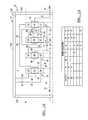
- FIG. 1Ais a schematic diagram of a transmission according to the principles of the present invention.
- FIG. 1Bis a chart showing feasible locations of the torque transmitting devices for the arrangement of the transmission shown in FIG. 1A ;
- FIG. 1Cis a schematic diagram of another arrangement of the transmission according to the principles of the present invention.
- FIG. 1Dis a chart showing feasible locations of the torque transmitting devices for the arrangement of the transmission shown in FIG. 1C ;
- FIG. 2Ais a schematic diagram of still another arrangement of the transmission according to the principles of the present invention.
- FIG. 2Bis a chart showing feasible locations of the torque transmitting devices for the arrangement of the transmission shown in FIG. 2A ;
- FIG. 3Ais a schematic diagram of still another arrangement of the transmission according to the principles of the present invention.
- FIG. 3Bis a chart showing feasible locations of the torque transmitting devices for the arrangement of the transmission shown in FIG. 3A ;
- FIG. 4Ais a schematic diagram of still another arrangement of the transmission according to the principles of the present invention.
- FIG. 4Bis a chart showing feasible locations of the torque transmitting devices for the arrangement of the transmission shown in FIG. 4A ;
- FIG. 5Ais a schematic diagram of still another arrangement of the transmission according to the principles of the present invention.
- FIG. 5Bis a chart showing feasible locations of the torque transmitting devices for the arrangement of the transmission shown in FIG. 5A ;
- FIG. 6Ais a schematic diagram of still another arrangement of the transmission according to the principles of the present invention.
- FIG. 6Bis a chart showing feasible locations of the torque transmitting devices for the arrangement of the transmission shown in FIG. 6A ;
- FIG. 7Ais a schematic diagram of still another arrangement of the transmission according to the principles of the present invention.
- FIG. 7Bis a chart showing feasible locations of the torque transmitting devices for the arrangement of the transmission shown in FIG. 7A .
- the transmission 10is illustrated as a rear-wheel drive or longitudinal transmission, though various other types of transmission configurations may be employed.
- the transmission 10includes a transmission housing 11 , an input shaft or member 12 , and an output shaft or member 14 .
- the input member 12is continuously connected to an engine (not shown) or to a turbine of a torque converter (not shown).
- the output member 14is continuously connected with a final drive unit (not shown) or transfer case (not shown).
- the transmission 10includes a first planetary gear set 16 , a second planetary gear set 18 , a third planetary gear set 20 , and a fourth planetary gear set 22 .
- the planetary gear sets 16 , 18 , 20 and 22are connected between the input member 12 and the output member 14 .
- the planetary gear set 16includes a sun gear member 24 , a ring gear member 26 , and a planet carrier member 28 that rotatably supports a set of planet or pinion gears 30 (only one of which is shown).
- the pinion gears 30are configured to intermesh with the sun gear member 24 and the ring gear member 26 .
- the sun gear member 24is connected for common rotation with a first shaft or intermediate member 32 and a second shaft or intermediate member 34 . It should be appreciated that the first intermediate member 32 is connected for common rotation with the second intermediate member 34 and that the intermediate members 32 and 34 may form one single shaft or multiple shafts through one or more members of the planetary gear sets, as seen throughout the several views.
- the ring gear member 26is connected for common rotation with a third shaft or intermediate member 36 .
- the planet carrier member 28is connected for common rotation with a fourth shaft or intermediate member 38 .
- the planetary gear set 18includes a sun gear member 42 , a ring gear member 44 , and a planet carrier member 46 that rotatably supports a set of planet or pinion gears 48 .
- the pinion gears 48are configured to intermesh with the sun gear member 42 and the ring gear member 44 .
- the sun gear member 42is connected for common rotation with the second intermediate member 34 .
- the ring gear member 44is connected for common rotation with a fifth shaft or intermediate member 50 .
- the planet carrier member 46is connected for common rotation with the input member 12 .
- the planetary gear set 20includes a sun gear member 52 , a ring gear member 54 , and a carrier member 56 that rotatably supports a set of planet or pinion gears 58 .
- the pinion gears 58are configured to intermesh with the sun gear member 52 and the ring gear member 54 .
- the sun gear member 52is connected for common rotation with the fifth shaft or intermediate member 50 and with a sixth shaft or intermediate member 51 . It should be appreciated that the fifth intermediate member 50 is connected for common rotation with the sixth intermediate member 51 and that the intermediate members 50 and 51 may form one single shaft or multiple shafts through one or more members of the planetary gear sets, as seen throughout the several views.
- the ring gear member 54is connected for common rotation with a seventh shaft or intermediate member 60 .
- the planet carrier member 56is connected for common rotation with an eighth shaft or intermediate member 62 .
- the eighth intermediate member 62is connected for common rotation with the output member 14 and that the eighth intermediate members 62 and the output member 14 may form one single shaft or multiple shafts through one or more members of the planetary gear sets, as seen throughout the several views.
- the planetary gear set 22includes a sun gear member 72 , a ring gear member 74 , and a planet carrier member 76 that rotatably supports a set of planet or pinion gears 78 .
- the pinion gears 78are configured to intermesh with the sun gear member 72 and the ring gear member 74 .
- the sun gear member 72is connected for common rotation with a ninth shaft or intermediate member 64 and a tenth shaft or intermediate member 66 . It should be appreciated that the ninth intermediate member 64 is connected for common rotation with the tenth intermediate member 66 and that the intermediate members 64 and 66 may form one single shaft or multiple shafts through one or more members of the planetary gear sets, as seen throughout the several views.
- the ring gear member 74is connected for common rotation with the fourth intermediate member 38 .
- the planet carrier member 76is connected for common rotation with the output member 14 and with the eighth intermediate member 62 .
- the transmission 10includes a variety of torque-transmitting mechanisms or devices including a first intermediate clutch C 1 , a second intermediate clutch C 2 , a third intermediate clutch C 3 , a first brake B 1 and a second brake B 2 .
- the first intermediate clutch C 1is selectively engagable to connect the input member 12 to the tenth intermediate member 66 .
- the first intermediate clutch C 1may be connected to the input member 12 through the planet carrier member 46 , as seen throughout the several views.
- the second intermediate clutch C 2is selectively engagable to connect the sixth intermediate member 51 to the ninth intermediate member 64 .
- the third intermediate clutch C 3is selectively engagable to connect the seventh intermediate member 60 to the ninth intermediate member 64 .
- the brake B 1is selectively engagable to connect the first intermediate member 32 to the transmission housing 11 to restrict rotation of the first intermediate member 32 relative to the transmission housing 11 .
- the brake B 2is selectively engagable to connect the third intermediate member 36 to the transmission housing 11 to restrict rotation of the third intermediate member 36 relative to the transmission housing 11 .
- the transmission 10is capable of transmitting torque from the input member 12 to the output member 14 in at least eight forward torque ratios and one reverse torque ratio.
- Each of the forward torque ratios and the reverse torque ratioare attained by engagement of one or more of the torque-transmitting mechanisms (i.e. first intermediate clutch C 1 , second intermediate clutch C 2 , third intermediate clutch C 3 , brake B 1 and brake B 2 ).
- first intermediate clutch C 1second intermediate clutch C 2
- third intermediate clutch C 3i.e. first intermediate clutch C 1 , second intermediate clutch C 2 , third intermediate clutch C 3 , brake B 1 and brake B 2 .
- Those skilled in the artwill readily understand that a different speed ratio is associated with each torque ratio.
- eight forward speed ratiosmay be attained by the transmission 10 .
- the transmission housing 11includes a first end wall 102 , a second end wall 104 , and a third wall 106 .
- the third wall 106interconnects between the first and second end walls 102 and 104 to provide a space or cavity 108 in which planetary gear sets 16 , 18 , 20 , and 22 and the torque-transmitting mechanisms C 1 , C 2 , C 3 , B 1 , and B 2 are located.
- the cavity 108has a plurality of areas or Zones A, B, C, D, E, and F in which the plurality of torque transmitting mechanisms C 1 , C 2 , C 3 , B 1 , and B 2 will be specifically positioned, in accordance with the preferred embodiments of the present invention.
- Zone Ais defined by the area or space bounded: axially on the left by the first end wall 102 , on the right by planetary gear set 16 , radially inward by a reference line “L” which is a longitudinal line that is axially aligned with the input shaft 12 , and radially outward by a reference line “M” which is a longitudinal line that extends adjacent an outer diameter or outer periphery of the planetary gear sets 16 , 18 , 20 , and 22 .
- Zone Bis defined by the area bounded: axially on the left by planetary gear set 16 , axially on the right by the planetary gear set 18 , radially outward by reference line “M”, and radially inward by reference line “L”.
- Zone Cis defined by the area bounded: axially on the left by the planetary gear set 18 , axially on the right by the planetary gear set 20 , radially outward by reference line “M”, and radially inward by reference line “L”.
- Zone Dis defined by the area bounded: axially on the left by the planetary gear set 20 , axially on the right by the planetary gear set 22 , radially outward by reference line “M”, and radially inward by reference line “L”.
- Zone Eis defined by the area bounded: axially on the left by the planetary gear set 22 , axially on the right by the second end wall 104 , radially outward by reference line “M”, and radially inward by reference line “L”.
- Zone Fis defined by the area bounded: axially on the left by the first end wall 102 , axially on the right by the second end wall 104 , radially inward by reference line “M” and radially outward by the third wall 106 .
- planetary gear sets 16 , 18 , 20 , and 22will change positions within the transmission cavity 108 , however, the Zones described above will not change and will remain the same as shown throughout the Figures.
- the planetary gear sets 16 , 18 , 20 , and 22are longitudinally arranged in the following order from left to right: 16 - 18 - 20 - 22 .
- the planetary gear set 16is disposed closest to the wall 102
- the planetary gear set 22is disposed closest to the wall 104
- the planetary gear set 18is adjacent the planetary gear set 16
- the planetary gear set 20is disposed between the planetary gear sets 18 and 22 .
- the torque-transmitting mechanismsare intentionally located within specific Zones in order to provide advantages in overall transmission size, packaging efficiency, and reduced manufacturing complexity.
- the torque-transmitting mechanism C 1is disposed within Zone C
- the torque-transmitting mechanisms C 2 and C 3are disposed within Zone D
- the torque-transmitting mechanisms B 1 and B 2are disposed within Zone F.
- the present inventioncontemplates other embodiments where the torque-transmitting mechanisms C 1 , C 2 , C 3 , B 1 , and B 2 are disposed in the other Zones.
- the feasible locations of the torque-transmitting devices C 1 , C 2 , C 3 , B 1 , and B 2 relative to the Zonesare illustrated in the chart shown in FIG. 1B .
- An “X” in the chartindicates that the present invention contemplates locating the particular torque-transmitting device in any of the referenced Zones.
- the transmission 10 Bincludes the planetary gear sets 16 , 18 , 20 , and 22 and the torque-transmitting mechanisms C 1 , C 2 , C 3 , B 1 , and B 2 .
- the various components and connecting shafts that are identical with the transmission 10 in FIG. 1Ahave the same numerical designation.
- the transmission 10 Bincludes the planetary gear sets 16 , 18 , 20 , and 22 longitudinally arranged identically to the arrangement shown in FIG. 1A .
- the torque-transmitting mechanisms C 1 and C 2are disposed within Zone B.
- the torque-transmitting mechanism C 3is disposed within Zone D and the torque-transmitting mechanisms B 1 and B 2 are disposed within Zone F.
- the present inventioncontemplates other embodiments of transmission 10 B where the torque-transmitting mechanisms C 1 , C 2 , C 3 , B 1 , and B 2 are disposed in the other Zones.
- the feasible locations of the torque-transmitting devices C 1 , C 2 , C 3 , B 1 , and B 2 relative to the Zonesare illustrated in the chart shown in FIG. 1D .
- An “X” in the chartindicates that the present invention contemplates locating the particular torque-transmitting device in any of the referenced Zones.
- the transmission 200includes the planetary gear sets 16 , 18 , 20 , and 22 and the torque-transmitting mechanisms C 1 , C 2 , C 3 , B 1 , and B 2 .
- the various components and connecting shafts that are identical with the transmission 10 in FIG. 1Ahave the same numerical designation in FIG. 2A .
- the transmission 200includes the planetary gear sets 16 , 18 , 20 , and 22 longitudinally arranged in the following order from left to right: 18 - 20 - 16 - 22 .
- the planetary gear set 18is disposed closest to the wall 102
- the planetary gear set 22is disposed closest to the wall 104
- the planetary gear set 20is adjacent the planetary gear set 18
- the planetary gear set 16is disposed between the planetary gear sets 20 and 22 .
- the torque-transmitting mechanismsare intentionally located within specific Zones in order to provide advantages in overall transmission size, packaging efficiency, and reduced manufacturing complexity.
- the torque-transmitting mechanisms C 1 and C 2are disposed within Zone A
- the torque-transmitting mechanism C 3is disposed within Zone C
- the torque-transmitting mechanisms B 1 and B 2are disposed within Zone F.
- the present inventioncontemplates other embodiments of the transmission 200 where the torque-transmitting mechanisms C 1 , C 2 , C 3 , B 1 , and B 2 are disposed in the other Zones.
- the feasible locations of the torque-transmitting devices C 1 , C 2 , C 3 , B 1 , and B 2 relative to the Zonesare illustrated in the chart shown in FIG. 2B .
- An “X” in the chartindicates that the present invention contemplates locating the particular torque-transmitting device in any of the referenced Zones.
- the transmission 300includes the planetary gear sets 16 , 18 , 20 , and 22 and the torque-transmitting mechanisms C 1 , C 2 , C 3 , B 1 , and B 2 .
- the various components and connecting shafts that are identical with the transmission 10 in FIG. 1Ahave the same numerical designation in FIG. 3A .
- the transmission 300includes the planetary gear sets 16 , 18 , 20 , and 22 longitudinally arranged identically to the arrangement shown in FIG. 2A .
- the input shaft 12is arranged such that it crosses the boundary between Zones A and F.
- the torque-transmitting mechanisms C 1 and C 2are disposed within Zone A
- the torque-transmitting mechanism C 3is disposed within Zone C
- the torque-transmitting mechanisms B 1 and B 2are disposed within Zone F.
- the present inventioncontemplates other embodiments of the transmission 300 where the torque-transmitting mechanisms C 1 , C 2 , C 3 , B 1 , and B 2 are disposed in the other Zones.
- the feasible locations of the torque-transmitting devices C 1 , C 2 , C 3 , B 1 , and B 2 relative to the Zonesare illustrated in the chart shown in FIG. 3B .
- An “X” in the chartindicates that the present invention contemplates locating the particular torque-transmitting device in any of the referenced Zones.
- the transmission 400includes the planetary gear sets 16 , 18 , 20 , and 22 and the torque-transmitting mechanisms C 1 , C 2 , C 3 , B 1 , and B 2 .
- the various components and connecting shafts that are identical with the transmission 10 in FIG. 1Ahave the same numerical designation in FIG. 4A .
- the transmission 400includes the planetary gear sets 16 , 18 , 20 , and 22 longitudinally arranged in the following order from left to right: 18 - 16 - 20 - 22 .
- the planetary gear set 18is disposed closest to the wall 102
- the planetary gear set 22is disposed closest to the wall 104
- the planetary gear set 16is adjacent the planetary gear set 18
- the planetary gear set 20is disposed between the planetary gear sets 16 and 22 .
- the torque-transmitting mechanismsare intentionally located within specific Zones in order to provide advantages in overall transmission size, packaging efficiency, and reduced manufacturing complexity.
- the torque-transmitting mechanisms C 1 and C 2are disposed within Zone A
- the torque-transmitting mechanism C 3is disposed within Zone C
- the torque-transmitting mechanisms B 1 and B 2are disposed within Zone F.
- the present inventioncontemplates other embodiments of the transmission 400 where the torque-transmitting mechanisms C 1 , C 2 , C 3 , B 1 , and B 2 are disposed in the other Zones.
- the feasible locations of the torque-transmitting devices C 1 , C 2 , C 3 , B 1 , and B 2 relative to the Zonesare illustrated in the chart shown in FIG. 4B .
- An “X” in the chartindicates that the present invention contemplates locating the particular torque-transmitting device in any of the referenced Zones.
- the transmission 500includes the planetary gear sets 16 , 18 , 20 , and 22 and the torque-transmitting mechanisms C 1 , C 2 , C 3 , B 1 , and B 2 .
- the various components and connecting shafts that are identical with the transmission 10 in FIG. 1Ahave the same numerical designation in FIG. 5A .
- the transmission 500includes the planetary gear sets 16 , 18 , 20 , and 22 longitudinally arranged in the following order from left to right: 18 - 16 - 22 - 20 .
- the planetary gear set 18is disposed closest to the wall 102
- the planetary gear set 20is disposed closest to the wall 104
- the planetary gear set 16is adjacent the planetary gear set 18
- the planetary gear set 22is disposed between the planetary gear sets 16 and 20 .
- the torque-transmitting mechanismsare intentionally located within specific Zones in order to provide advantages in overall transmission size, packaging efficiency, and reduced manufacturing complexity.
- the torque-transmitting mechanisms C 1 and C 2are disposed within Zone A
- the torque-transmitting mechanism C 3is disposed within Zone D
- the torque-transmitting mechanisms B 1 and B 2are disposed within Zone F.
- the present inventioncontemplates other embodiments of the transmission 500 where the torque-transmitting mechanisms C 1 , C 2 , C 3 , B 1 , and B 2 are disposed in the other Zones.
- the feasible locations of the torque-transmitting devices C 1 , C 2 , C 3 , B 1 , and B 2 relative to the Zonesare illustrated in the chart shown in FIG. 5B .
- An “X” in the chartindicates that the present invention contemplates locating the particular torque-transmitting device in any of the referenced Zones.
- the transmission 600includes the planetary gear sets 16 , 18 , 20 , and 22 and the torque-transmitting mechanisms C 1 , C 2 , C 3 , B 1 , and B 2 .
- the various components and connecting shafts that are identical with the transmission 10 in FIG. 1Ahave the same numerical designation in FIG. 6A .
- the transmission 600includes the planetary gear sets 16 , 18 , 20 , and 22 longitudinally arranged in the following order from left to right: 20 - 18 - 16 - 22 .
- the planetary gear set 20is disposed closest to the wall 102
- the planetary gear set 22is disposed closest to the wall 104
- the planetary gear set 18is adjacent the planetary gear set 20
- the planetary gear set 16is disposed between the planetary gear sets 18 and 22 .
- the torque-transmitting mechanismsare intentionally located within specific Zones in order to provide advantages in overall transmission size, packaging efficiency, and reduced manufacturing complexity.
- the torque-transmitting mechanisms C 1 , C 2 , B 1 , and B 2are disposed within Zone F
- the torque-transmitting mechanism C 3is disposed within Zone A.
- the present inventioncontemplates other embodiments of the transmission 600 where the torque-transmitting mechanisms C 1 , C 2 , C 3 , B 1 , and B 2 are disposed in the other Zones.
- the feasible locations of the torque-transmitting devices C 1 , C 2 , C 3 , B 1 , and B 2 relative to the Zonesare illustrated in the chart shown in FIG. 6B .
- An “X” in the chartindicates that the present invention contemplates locating the particular torque-transmitting device in any of the referenced Zones.
- the transmission 700includes the planetary gear sets 16 , 18 , 20 , and 22 and the torque-transmitting mechanisms C 1 , C 2 , C 3 , B 1 , and B 2 .
- the various components and connecting shafts that are identical with the transmission 10 in FIG. 1Ahave the same numerical designation in FIG. 7A .
- the transmission 700includes the planetary gear sets 16 , 18 , 20 , and 22 longitudinally arranged in the following order from left to right: 20 - 22 - 18 - 16 .
- the planetary gear set 20is disposed closest to the wall 102
- the planetary gear set 16is disposed closest to the wall 104
- the planetary gear set 22is adjacent the planetary gear set 20
- the planetary gear set 18is disposed between the planetary gear sets 22 and 16 .
- the torque-transmitting mechanismsare intentionally located within specific Zones in order to provide advantages in overall transmission size, packaging efficiency, and reduced manufacturing complexity.
- the torque-transmitting mechanisms C 1 , C 2 , and C 3are disposed within Zone B
- the torque-transmitting mechanism B 1is disposed within Zone F
- the torque-transmitting mechanism B 2is disposed within Zone E.
- the present inventioncontemplates other embodiments of the transmission 700 where the torque-transmitting mechanisms C 1 , C 2 , C 3 , B 1 , and B 2 are disposed in the other Zones.
- the feasible locations of the torque-transmitting devices C 1 , C 2 , C 3 , B 1 , and B 2 relative to the Zonesare illustrated in the chart shown in FIG. 7B .
- An “X” in the chartindicates that the present invention contemplates locating the particular torque-transmitting device in any of the referenced Zones.
Landscapes
- Engineering & Computer Science (AREA)
- General Engineering & Computer Science (AREA)
- Mechanical Engineering (AREA)
- Structure Of Transmissions (AREA)
Abstract
Description
Claims (22)
Priority Applications (1)
| Application Number | Priority Date | Filing Date | Title |
|---|---|---|---|
| US12/826,206US7867128B2 (en) | 2007-03-16 | 2010-06-29 | Multi-speed transmission |
Applications Claiming Priority (3)
| Application Number | Priority Date | Filing Date | Title |
|---|---|---|---|
| US89541107P | 2007-03-16 | 2007-03-16 | |
| US11/746,396US7775931B2 (en) | 2007-03-16 | 2007-05-09 | Multi-speed transmission |
| US12/826,206US7867128B2 (en) | 2007-03-16 | 2010-06-29 | Multi-speed transmission |
Related Parent Applications (1)
| Application Number | Title | Priority Date | Filing Date |
|---|---|---|---|
| US11/746,396DivisionUS7775931B2 (en) | 2007-03-16 | 2007-05-09 | Multi-speed transmission |
Publications (2)
| Publication Number | Publication Date |
|---|---|
| US20100267514A1 US20100267514A1 (en) | 2010-10-21 |
| US7867128B2true US7867128B2 (en) | 2011-01-11 |
Family
ID=39719869
Family Applications (7)
| Application Number | Title | Priority Date | Filing Date |
|---|---|---|---|
| US11/746,396Expired - Fee RelatedUS7775931B2 (en) | 2007-03-16 | 2007-05-09 | Multi-speed transmission |
| US12/826,196Expired - Fee RelatedUS7867130B2 (en) | 2007-03-16 | 2010-06-29 | Multi-speed transmission |
| US12/826,206Expired - Fee RelatedUS7867128B2 (en) | 2007-03-16 | 2010-06-29 | Multi-speed transmission |
| US12/826,199Expired - Fee RelatedUS7878940B2 (en) | 2007-03-16 | 2010-06-29 | Multi-speed transmission |
| US12/826,180Expired - Fee RelatedUS7867129B2 (en) | 2007-03-16 | 2010-06-29 | Multi-speed transmission |
| US12/826,171Expired - Fee RelatedUS7862466B2 (en) | 2007-03-16 | 2010-06-29 | Multi-speed transmission |
| US12/826,186Expired - Fee RelatedUS7862467B2 (en) | 2007-03-16 | 2010-06-29 | Multi-speed transmission |
Family Applications Before (2)
| Application Number | Title | Priority Date | Filing Date |
|---|---|---|---|
| US11/746,396Expired - Fee RelatedUS7775931B2 (en) | 2007-03-16 | 2007-05-09 | Multi-speed transmission |
| US12/826,196Expired - Fee RelatedUS7867130B2 (en) | 2007-03-16 | 2010-06-29 | Multi-speed transmission |
Family Applications After (4)
| Application Number | Title | Priority Date | Filing Date |
|---|---|---|---|
| US12/826,199Expired - Fee RelatedUS7878940B2 (en) | 2007-03-16 | 2010-06-29 | Multi-speed transmission |
| US12/826,180Expired - Fee RelatedUS7867129B2 (en) | 2007-03-16 | 2010-06-29 | Multi-speed transmission |
| US12/826,171Expired - Fee RelatedUS7862466B2 (en) | 2007-03-16 | 2010-06-29 | Multi-speed transmission |
| US12/826,186Expired - Fee RelatedUS7862467B2 (en) | 2007-03-16 | 2010-06-29 | Multi-speed transmission |
Country Status (4)
| Country | Link |
|---|---|
| US (7) | US7775931B2 (en) |
| JP (1) | JP4691073B2 (en) |
| CN (1) | CN101265959B (en) |
| DE (1) | DE202007007702U1 (en) |
Families Citing this family (41)
| Publication number | Priority date | Publication date | Assignee | Title |
|---|---|---|---|---|
| DE102005002337A1 (en)* | 2005-01-17 | 2006-08-10 | Zf Friedrichshafen Ag | Multi-speed transmission |
| DE102006023302B4 (en)* | 2006-05-18 | 2011-09-22 | Zf Friedrichshafen Ag | Multi-speed transmission |
| US7699741B2 (en)* | 2007-01-25 | 2010-04-20 | Gm Global Technology Operations, Inc. | Multi-speed transmission |
| US8012059B2 (en)* | 2007-05-30 | 2011-09-06 | GM Global Technology Operations LLC | Multi-speed automatic transmission |
| JP2010156351A (en)* | 2007-09-25 | 2010-07-15 | Komatsu Ltd | Planetary gear type gearbox |
| US8197378B2 (en)* | 2008-02-20 | 2012-06-12 | GM Global Technology Operations LLC | Multi-speed transaxle for a front wheel drive vehicle |
| US8118700B2 (en)* | 2008-02-20 | 2012-02-21 | GM Global Technology Operations LLC | Multi-speed transmission for a front wheel drive vehicle |
| US8123650B2 (en)* | 2008-02-20 | 2012-02-28 | GM Global Technology Operations LLC | Multi-speed transaxle for a front wheel drive vehicle |
| US8187138B2 (en)* | 2008-02-21 | 2012-05-29 | GM Global Technology Operations LLC | Multi-speed transaxle for a front wheel drive vehicle |
| US8075441B2 (en)* | 2008-03-31 | 2011-12-13 | GM Global Technology Operations LLC | Automatic transmission gear and clutch arrangement |
| US8267832B2 (en)* | 2008-04-16 | 2012-09-18 | GM Global Technology Operations LLC | Multi-speed transaxle |
| US7998015B2 (en)* | 2008-04-17 | 2011-08-16 | GM Global Technology Operations LLC | Multi-speed transaxle for a front wheel drive vehicle |
| US8167767B2 (en)* | 2008-04-18 | 2012-05-01 | GM Global Technology Operations LLC | Multi-speed transaxle |
| US8192320B2 (en)* | 2008-04-18 | 2012-06-05 | GM Global Technology Operations LLC | Multi-speed transaxle |
| US8241167B2 (en)* | 2008-04-21 | 2012-08-14 | GM Global Technology Operations LLC | Multi-speed transaxle |
| US8206252B2 (en)* | 2008-05-09 | 2012-06-26 | GM Global Technology Operations LLC | Hybrid powertrain having a multi-speed transmission |
| US8292767B2 (en)* | 2008-06-04 | 2012-10-23 | GM Global Technology Operations LLC | Powertrain having a multi-speed transmission |
| US8033948B2 (en)* | 2009-02-13 | 2011-10-11 | GM Global Technology Operations LLC | Multi-speed transmission |
| US8105196B2 (en)* | 2009-05-01 | 2012-01-31 | GM Global Technology Operations LLC | Automatic transmission gear and clutch arrangement |
| DE102010040001A1 (en)* | 2010-08-31 | 2012-03-01 | Zf Friedrichshafen Ag | Planetary-type multi-stage reduction gear box i.e. automatic gear box, for e.g. passenger car, has shaft connected with ring gears of planetary gear train and sun wheel of another planetary gear train |
| DE102010040000A1 (en)* | 2010-08-31 | 2012-03-01 | Zf Friedrichshafen Ag | Multi-step planetary gearbox for motor vehicle, has planetary gear trains that are selectively engaged with shafts so that various transmission ratios are produced between drive and driven shafts to realize forward and reverse gears |
| DE102010039998A1 (en)* | 2010-08-31 | 2012-03-01 | Zf Friedrichshafen Ag | Multistage gearbox, particularly automatic gearbox for motor vehicle, has drive shaft, output shaft and four planetary wheel sets, which are arranged in housing |
| DE102010039990A1 (en)* | 2010-08-31 | 2012-03-01 | Zf Friedrichshafen Ag | Multi-step planetary gear box for motor vehicle, has planetary gear sets that are connected together via shafts and clutches, and drive and driven shafts connected to webs of planetary gear sets, respectively |
| DE102010039989A1 (en)* | 2010-08-31 | 2012-03-01 | Zf Friedrichshafen Ag | Multistage gearbox, particularly automatic gearbox for motor vehicle, has drive shaft, output shaft and four planetary wheel sets, which are arranged in housing |
| DE102010040002A1 (en)* | 2010-08-31 | 2012-03-01 | Zf Friedrichshafen Ag | Multistage gearbox, particularly automatic gearbox for motor vehicle, has drive shaft, output shaft and four planetary wheel sets, which are arranged in housing |
| DE102010039996A1 (en)* | 2010-08-31 | 2012-03-01 | Zf Friedrichshafen Ag | Multi-step planetary reduction gearbox for motor vehicle, has planetary gear trains selectively engaged with shafts so that various transmission ratios are produced between drive and driven shafts to realize forward and reverse gears |
| DE102010039997A1 (en)* | 2010-08-31 | 2012-03-01 | Zf Friedrichshafen Ag | Planetary-type multi-stage reduction gear box i.e. automatic gear box, for e.g. passenger car, has shaft connected with bar of planetary gear train, and driven shaft connected with bar of another planetary gear train over clutch |
| US9163704B2 (en)* | 2011-01-10 | 2015-10-20 | Gm Global Technology Operations, Llc | Clutch and gear arrangement for a front wheel drive vehicle |
| US8678972B2 (en)* | 2011-10-03 | 2014-03-25 | GM Global Technology Operations LLC | Multi-speed transmission |
| US8506442B2 (en)* | 2011-10-03 | 2013-08-13 | GM Global Technology Operations LLC | Multi-speed transmission |
| US9618087B2 (en) | 2012-06-14 | 2017-04-11 | GM Global Technology Operations LLC | Automatic transmission gear and clutch arrangement |
| US9068630B2 (en)* | 2013-01-03 | 2015-06-30 | Ford Global Technologies, Llc | Multi-speed transmission |
| US9625007B2 (en)* | 2014-08-12 | 2017-04-18 | Allison Transmission, Inc. | Multi-speed transmission |
| WO2016024951A1 (en)* | 2014-08-12 | 2016-02-18 | Allison Transmission, Inc. | Multi-speed transmission |
| US9512905B2 (en)* | 2014-10-27 | 2016-12-06 | Allison Transmission, Inc. | Multi-speed transmission |
| DE102014226232A1 (en)* | 2014-12-17 | 2016-06-23 | Zf Friedrichshafen Ag | Multi-stage automatic transmission |
| US9927009B2 (en)* | 2015-04-23 | 2018-03-27 | Allison Transmission, Inc. | Multi-speed transmission |
| EP3286453A4 (en)* | 2015-04-24 | 2018-12-05 | Allison Transmission, Inc. | Multi-speed transmission |
| KR101724470B1 (en)* | 2015-06-15 | 2017-04-07 | 현대자동차 주식회사 | Planetary gear train of automatic transmission for vehicles |
| DE102015011519B4 (en)* | 2015-09-03 | 2020-07-09 | Audi Ag | Method for operating a multi-speed transmission in a motor vehicle |
| DE102021200165B4 (en) | 2021-01-11 | 2023-12-28 | Zf Friedrichshafen Ag | Operating a multi-speed vehicle transmission |
Citations (53)
| Publication number | Priority date | Publication date | Assignee | Title |
|---|---|---|---|---|
| US6558287B2 (en) | 2001-03-29 | 2003-05-06 | Aisin Aw Co., Ltd. | Automatic transmission for a vehicle |
| US6634981B1 (en) | 2002-04-16 | 2003-10-21 | General Motors Corporation | Family of transmission mechanisms with three planetary gear sets and a stationary member |
| US6648790B2 (en) | 2002-02-25 | 2003-11-18 | General Motors Corporation | Family of multi-speed transmission mechanisms having three planetary gear sets and six torque-transmitting devices |
| US6659904B1 (en) | 2002-06-18 | 2003-12-09 | General Motors Corporation | Multi-speed planetary transmissions with three interconnected gear sets |
| US6659903B1 (en) | 2002-06-18 | 2003-12-09 | General Motors Corporation | Multi-speed transmissions with three gear sets and a stationary planetary member |
| US6709360B2 (en) | 2002-08-02 | 2004-03-23 | General Motors Corporation | Family of multi-speed transmission mechanisms with three input clutches and three planetary gearsets |
| US20040082425A1 (en) | 2002-10-23 | 2004-04-29 | Lee Chunhao J. | Planetary transmissions with clutched input and a stationary member |
| US6746360B2 (en) | 2002-09-12 | 2004-06-08 | General Motors Corporation | Transmission mechanisms with clutched input and a stationary planetary gear member |
| US6887178B2 (en) | 2001-10-30 | 2005-05-03 | Toyota Jidosha Kabushiki Kaisha | Automatic transmission |
| US6910985B2 (en) | 2001-05-30 | 2005-06-28 | Jatco Ltd | Gear-operated speed change apparatus for automatic transmission |
| US6913556B2 (en) | 2003-10-24 | 2005-07-05 | General Motors Corporation | Power transmission for a vehicle |
| US6923742B2 (en) | 2003-10-24 | 2005-08-02 | General Motors Corporation | Power transmission for a vehicle |
| US6929576B2 (en) | 2003-10-24 | 2005-08-16 | General Motors Corporation | Power transmission for a vehicle |
| US6949048B2 (en) | 2004-02-10 | 2005-09-27 | General Motors Corporation | Wide ratio transmissions with three planetary gear sets and two brakes |
| US6960150B2 (en) | 2003-10-24 | 2005-11-01 | General Motors Corporation | Power transmission for a vehicle |
| US6962548B2 (en) | 2004-02-10 | 2005-11-08 | General Motors Corporation | Wide ratio transmissions with a stationary planetary gear member and at least five clutches |
| US20050282680A1 (en) | 2004-06-21 | 2005-12-22 | Soh Byeong H | Multiple speed automatic transmission for a vehicle |
| US7014590B2 (en) | 2003-06-24 | 2006-03-21 | General Motors Corporation | Seven-speed transmission |
| US20060068965A1 (en) | 2002-07-11 | 2006-03-30 | Gerhard Gumpoltsberger | Multi-stage transmission |
| US7033299B2 (en) | 2004-06-16 | 2006-04-25 | General Motors Corporation | Planetary transmissions having three interconnected gear sets and clutched input |
| US7059995B2 (en) | 2003-06-24 | 2006-06-13 | General Motors Corporation | Seven- or eight-speed transmission |
| US7074153B2 (en) | 2004-08-18 | 2006-07-11 | General Motors Corporation | Planetary transmissions having three gear sets and input clutches |
| US7081066B2 (en) | 2004-08-18 | 2006-07-25 | General Motors Corporation | Planetary transmissions having three non-continuously interconnected gear sets |
| US7094173B2 (en) | 2004-06-04 | 2006-08-22 | General Motors Corporation | Wide ratio transmissions having a stationary planetary member and at least four clutches |
| US7101305B2 (en) | 2003-05-27 | 2006-09-05 | Toyota Jidosha Kabushiki Kaisha | Planetary-gear-type multiple-step transmission for vehicle |
| US7101303B2 (en) | 2003-09-04 | 2006-09-05 | Zf Friedrichshafen Ag | Multiple gear stage automatic transmission |
| US7104915B2 (en) | 2003-09-04 | 2006-09-12 | Zf Friedrichshafen Ag | Multiple gear stage automatic transmission |
| US7115063B2 (en) | 2003-09-04 | 2006-10-03 | Zf Friedrichshafen Ag | Multiple gear stage automatic transmission |
| US7115061B2 (en) | 2003-09-04 | 2006-10-03 | Zf Friedrichshafen Ag | Multiple gear stage automatic transmission |
| US7118510B2 (en) | 2004-07-23 | 2006-10-10 | General Motors Corporation | Planetary transmissions having input clutches and two interconnecting members |
| US7118511B2 (en) | 2003-09-04 | 2006-10-10 | Zf Friedrichshafen Ag | Multiple gear stage automatic transmission |
| US7118509B2 (en) | 2003-05-27 | 2006-10-10 | Toyota Jidosha Kabushiki Kaisha | Multiple-step transmission |
| US7137923B2 (en) | 2003-09-04 | 2006-11-21 | Zf Friedrichshafen Ag | Multiple gear stage automatic transmission |
| US7150696B2 (en) | 2004-08-24 | 2006-12-19 | General Motors Corporation | Planetary transmissions having a stationary gear member and clutched input members |
| US7150695B2 (en) | 2004-07-23 | 2006-12-19 | General Motors Corporation | Planetary transmissions having input clutches and three interconnected gear sets |
| US7156767B2 (en) | 2003-09-04 | 2007-01-02 | Zf Friedrichshafen Ag | Multiple gear stage automatic transmission |
| US7156768B2 (en) | 2003-01-21 | 2007-01-02 | Zf Friedrichshafen Ag | Multi-stage transmission |
| US20070010370A1 (en) | 2005-07-08 | 2007-01-11 | Madhusudan Raghavan | Multi-speed planetary transmissions having seven torque-transmitting devices and two fixed interconnections |
| US20070010367A1 (en) | 2005-07-08 | 2007-01-11 | Madhusudan Raghavan | Multi-speed planetary transmissions having seven torque-transmitting devices engaged in combinations of two |
| US20070010369A1 (en) | 2005-07-08 | 2007-01-11 | Bucknor Norman K | Multi-speed planetary transmissions having a stationary member and seven torque-transmitting devices |
| US20080085813A1 (en) | 2006-10-09 | 2008-04-10 | Hart James M | Multi-speed transmission |
| US20080085806A1 (en) | 2006-10-09 | 2008-04-10 | Wittkopp Scott H | Multi-speed transmission |
| US20080085811A1 (en) | 2006-10-09 | 2008-04-10 | Hart James M | Multi-speed transmission |
| US20080085809A1 (en) | 2006-10-09 | 2008-04-10 | Wittkopp Scott H | Multi-speed transmission |
| US20080085808A1 (en) | 2006-10-09 | 2008-04-10 | Hart James M | Multi-speed transmission |
| US20080085812A1 (en) | 2006-10-09 | 2008-04-10 | Wittkopp Scott H | Multi-speed transmission |
| US20080085810A1 (en) | 2006-10-09 | 2008-04-10 | Hart James M | Multi-speed transmission |
| US20080085807A1 (en) | 2006-10-09 | 2008-04-10 | Wittkopp Scott H | Multi-speed transmission |
| US20080283684A1 (en) | 2007-05-18 | 2008-11-20 | Gm Global Technology Operations, Inc. | Exhaust mounting system |
| US20090247343A1 (en)* | 2008-03-31 | 2009-10-01 | Gm Global Technology Operations, Inc. | Automatic transmission gear and clutch arrangement |
| US20090264238A1 (en)* | 2008-04-17 | 2009-10-22 | Gm Global Technology Operations, Inc. | Multi-speed transaxle for a front wheel drive vehicle |
| US20090280941A1 (en)* | 2008-05-09 | 2009-11-12 | Gm Global Technology Operations, Inc. | Hybrid powertrain having a multi-speed transmission |
| US20090305838A1 (en)* | 2008-06-04 | 2009-12-10 | Gm Global Technology Operations, Inc. | Powertrain having a multi-speed transmission |
Family Cites Families (16)
| Publication number | Priority date | Publication date | Assignee | Title |
|---|---|---|---|---|
| US6176803B1 (en) | 1999-09-28 | 2001-01-23 | Caterpillar Inc. | Transmission assembly with four planetary gear sets providing nine forward and one reverse gear ratio |
| DE10115985A1 (en) | 2001-03-30 | 2002-10-10 | Zahnradfabrik Friedrichshafen | Multi-speed transmission |
| DE10115983A1 (en) | 2001-03-30 | 2002-10-10 | Zahnradfabrik Friedrichshafen | Multi-speed transmission |
| DE10315709A1 (en)* | 2003-04-07 | 2004-10-21 | Zf Friedrichshafen Ag | Multi-stage automatic transmission |
| JP4380291B2 (en) | 2003-10-27 | 2009-12-09 | トヨタ自動車株式会社 | Planetary gear type multi-stage transmission for vehicles |
| US7011597B2 (en) | 2004-03-24 | 2006-03-14 | General Motors Corporation | Multi-speed transmission |
| DE102005002337A1 (en)* | 2005-01-17 | 2006-08-10 | Zf Friedrichshafen Ag | Multi-speed transmission |
| US7163484B2 (en) | 2005-01-24 | 2007-01-16 | General Motors Corporation | Eight-speed transmissions with four planetary gear sets |
| DE102005010210A1 (en)* | 2005-03-05 | 2006-09-14 | Zf Friedrichshafen Ag | Multi-speed transmission |
| US7341537B2 (en) | 2005-05-25 | 2008-03-11 | General Motors Corporation | Multi-speed transmission |
| US7204780B2 (en) | 2005-05-25 | 2007-04-17 | General Motors Corporation | Multi speed transmission |
| DE102005032001A1 (en) | 2005-07-08 | 2007-02-01 | Zf Friedrichshafen Ag | Multi-speed transmission |
| JPWO2007007707A1 (en)* | 2005-07-14 | 2009-01-29 | ヤマハマリン株式会社 | Outboard motor |
| DE102005032880B4 (en)* | 2005-07-14 | 2016-07-28 | Zf Friedrichshafen Ag | Multi-speed transmission |
| DE102006033087B4 (en) | 2006-07-14 | 2022-05-19 | Zf Friedrichshafen Ag | Hybrid drive for a vehicle |
| KR100897261B1 (en)* | 2006-11-06 | 2009-05-14 | 현대자동차주식회사 | 8-speed powertrain for automotive automatic transmission |
- 2007
- 2007-05-09USUS11/746,396patent/US7775931B2/ennot_activeExpired - Fee Related
- 2007-05-31DEDE202007007702Upatent/DE202007007702U1/ennot_activeExpired - Lifetime
- 2007-07-13JPJP2007183801Apatent/JP4691073B2/ennot_activeExpired - Fee Related
- 2008
- 2008-03-14CNCN2008100865167Apatent/CN101265959B/ennot_activeExpired - Fee Related
- 2010
- 2010-06-29USUS12/826,196patent/US7867130B2/ennot_activeExpired - Fee Related
- 2010-06-29USUS12/826,206patent/US7867128B2/ennot_activeExpired - Fee Related
- 2010-06-29USUS12/826,199patent/US7878940B2/ennot_activeExpired - Fee Related
- 2010-06-29USUS12/826,180patent/US7867129B2/ennot_activeExpired - Fee Related
- 2010-06-29USUS12/826,171patent/US7862466B2/ennot_activeExpired - Fee Related
- 2010-06-29USUS12/826,186patent/US7862467B2/ennot_activeExpired - Fee Related
Patent Citations (54)
| Publication number | Priority date | Publication date | Assignee | Title |
|---|---|---|---|---|
| US6558287B2 (en) | 2001-03-29 | 2003-05-06 | Aisin Aw Co., Ltd. | Automatic transmission for a vehicle |
| US6910985B2 (en) | 2001-05-30 | 2005-06-28 | Jatco Ltd | Gear-operated speed change apparatus for automatic transmission |
| US7029416B2 (en) | 2001-10-30 | 2006-04-18 | Toyota Jidosha Kabushiki Kaisha | Automatic transmission |
| US6887178B2 (en) | 2001-10-30 | 2005-05-03 | Toyota Jidosha Kabushiki Kaisha | Automatic transmission |
| US6648790B2 (en) | 2002-02-25 | 2003-11-18 | General Motors Corporation | Family of multi-speed transmission mechanisms having three planetary gear sets and six torque-transmitting devices |
| US6634981B1 (en) | 2002-04-16 | 2003-10-21 | General Motors Corporation | Family of transmission mechanisms with three planetary gear sets and a stationary member |
| US6659904B1 (en) | 2002-06-18 | 2003-12-09 | General Motors Corporation | Multi-speed planetary transmissions with three interconnected gear sets |
| US6659903B1 (en) | 2002-06-18 | 2003-12-09 | General Motors Corporation | Multi-speed transmissions with three gear sets and a stationary planetary member |
| US20060068965A1 (en) | 2002-07-11 | 2006-03-30 | Gerhard Gumpoltsberger | Multi-stage transmission |
| US6709360B2 (en) | 2002-08-02 | 2004-03-23 | General Motors Corporation | Family of multi-speed transmission mechanisms with three input clutches and three planetary gearsets |
| US6746360B2 (en) | 2002-09-12 | 2004-06-08 | General Motors Corporation | Transmission mechanisms with clutched input and a stationary planetary gear member |
| US20040082425A1 (en) | 2002-10-23 | 2004-04-29 | Lee Chunhao J. | Planetary transmissions with clutched input and a stationary member |
| US7156768B2 (en) | 2003-01-21 | 2007-01-02 | Zf Friedrichshafen Ag | Multi-stage transmission |
| US7118509B2 (en) | 2003-05-27 | 2006-10-10 | Toyota Jidosha Kabushiki Kaisha | Multiple-step transmission |
| US7101305B2 (en) | 2003-05-27 | 2006-09-05 | Toyota Jidosha Kabushiki Kaisha | Planetary-gear-type multiple-step transmission for vehicle |
| US7014590B2 (en) | 2003-06-24 | 2006-03-21 | General Motors Corporation | Seven-speed transmission |
| US7059995B2 (en) | 2003-06-24 | 2006-06-13 | General Motors Corporation | Seven- or eight-speed transmission |
| US7137923B2 (en) | 2003-09-04 | 2006-11-21 | Zf Friedrichshafen Ag | Multiple gear stage automatic transmission |
| US7156767B2 (en) | 2003-09-04 | 2007-01-02 | Zf Friedrichshafen Ag | Multiple gear stage automatic transmission |
| US7118511B2 (en) | 2003-09-04 | 2006-10-10 | Zf Friedrichshafen Ag | Multiple gear stage automatic transmission |
| US7115061B2 (en) | 2003-09-04 | 2006-10-03 | Zf Friedrichshafen Ag | Multiple gear stage automatic transmission |
| US7115063B2 (en) | 2003-09-04 | 2006-10-03 | Zf Friedrichshafen Ag | Multiple gear stage automatic transmission |
| US7104915B2 (en) | 2003-09-04 | 2006-09-12 | Zf Friedrichshafen Ag | Multiple gear stage automatic transmission |
| US7101303B2 (en) | 2003-09-04 | 2006-09-05 | Zf Friedrichshafen Ag | Multiple gear stage automatic transmission |
| US6960150B2 (en) | 2003-10-24 | 2005-11-01 | General Motors Corporation | Power transmission for a vehicle |
| US6913556B2 (en) | 2003-10-24 | 2005-07-05 | General Motors Corporation | Power transmission for a vehicle |
| US6923742B2 (en) | 2003-10-24 | 2005-08-02 | General Motors Corporation | Power transmission for a vehicle |
| US6929576B2 (en) | 2003-10-24 | 2005-08-16 | General Motors Corporation | Power transmission for a vehicle |
| US6962548B2 (en) | 2004-02-10 | 2005-11-08 | General Motors Corporation | Wide ratio transmissions with a stationary planetary gear member and at least five clutches |
| US6949048B2 (en) | 2004-02-10 | 2005-09-27 | General Motors Corporation | Wide ratio transmissions with three planetary gear sets and two brakes |
| US7094173B2 (en) | 2004-06-04 | 2006-08-22 | General Motors Corporation | Wide ratio transmissions having a stationary planetary member and at least four clutches |
| US7033299B2 (en) | 2004-06-16 | 2006-04-25 | General Motors Corporation | Planetary transmissions having three interconnected gear sets and clutched input |
| US20050282680A1 (en) | 2004-06-21 | 2005-12-22 | Soh Byeong H | Multiple speed automatic transmission for a vehicle |
| US7118510B2 (en) | 2004-07-23 | 2006-10-10 | General Motors Corporation | Planetary transmissions having input clutches and two interconnecting members |
| US7150695B2 (en) | 2004-07-23 | 2006-12-19 | General Motors Corporation | Planetary transmissions having input clutches and three interconnected gear sets |
| US7074153B2 (en) | 2004-08-18 | 2006-07-11 | General Motors Corporation | Planetary transmissions having three gear sets and input clutches |
| US7081066B2 (en) | 2004-08-18 | 2006-07-25 | General Motors Corporation | Planetary transmissions having three non-continuously interconnected gear sets |
| US7150696B2 (en) | 2004-08-24 | 2006-12-19 | General Motors Corporation | Planetary transmissions having a stationary gear member and clutched input members |
| US20070010367A1 (en) | 2005-07-08 | 2007-01-11 | Madhusudan Raghavan | Multi-speed planetary transmissions having seven torque-transmitting devices engaged in combinations of two |
| US20070010370A1 (en) | 2005-07-08 | 2007-01-11 | Madhusudan Raghavan | Multi-speed planetary transmissions having seven torque-transmitting devices and two fixed interconnections |
| US20070010369A1 (en) | 2005-07-08 | 2007-01-11 | Bucknor Norman K | Multi-speed planetary transmissions having a stationary member and seven torque-transmitting devices |
| US20080085808A1 (en) | 2006-10-09 | 2008-04-10 | Hart James M | Multi-speed transmission |
| US20080085806A1 (en) | 2006-10-09 | 2008-04-10 | Wittkopp Scott H | Multi-speed transmission |
| US20080085811A1 (en) | 2006-10-09 | 2008-04-10 | Hart James M | Multi-speed transmission |
| US20080085809A1 (en) | 2006-10-09 | 2008-04-10 | Wittkopp Scott H | Multi-speed transmission |
| US20080085813A1 (en) | 2006-10-09 | 2008-04-10 | Hart James M | Multi-speed transmission |
| US20080085812A1 (en) | 2006-10-09 | 2008-04-10 | Wittkopp Scott H | Multi-speed transmission |
| US20080085810A1 (en) | 2006-10-09 | 2008-04-10 | Hart James M | Multi-speed transmission |
| US20080085807A1 (en) | 2006-10-09 | 2008-04-10 | Wittkopp Scott H | Multi-speed transmission |
| US20080283684A1 (en) | 2007-05-18 | 2008-11-20 | Gm Global Technology Operations, Inc. | Exhaust mounting system |
| US20090247343A1 (en)* | 2008-03-31 | 2009-10-01 | Gm Global Technology Operations, Inc. | Automatic transmission gear and clutch arrangement |
| US20090264238A1 (en)* | 2008-04-17 | 2009-10-22 | Gm Global Technology Operations, Inc. | Multi-speed transaxle for a front wheel drive vehicle |
| US20090280941A1 (en)* | 2008-05-09 | 2009-11-12 | Gm Global Technology Operations, Inc. | Hybrid powertrain having a multi-speed transmission |
| US20090305838A1 (en)* | 2008-06-04 | 2009-12-10 | Gm Global Technology Operations, Inc. | Powertrain having a multi-speed transmission |
Also Published As
| Publication number | Publication date |
|---|---|
| US7862466B2 (en) | 2011-01-04 |
| US20100267513A1 (en) | 2010-10-21 |
| US7878940B2 (en) | 2011-02-01 |
| JP2008232419A (en) | 2008-10-02 |
| US7867130B2 (en) | 2011-01-11 |
| US20100267514A1 (en) | 2010-10-21 |
| US7775931B2 (en) | 2010-08-17 |
| US20100267515A1 (en) | 2010-10-21 |
| CN101265959B (en) | 2012-08-08 |
| CN101265959A (en) | 2008-09-17 |
| US7867129B2 (en) | 2011-01-11 |
| DE202007007702U1 (en) | 2008-08-28 |
| US20100267516A1 (en) | 2010-10-21 |
| US20080227587A1 (en) | 2008-09-18 |
| JP4691073B2 (en) | 2011-06-01 |
| US7862467B2 (en) | 2011-01-04 |
| US20100304917A1 (en) | 2010-12-02 |
| US20100267517A1 (en) | 2010-10-21 |
Similar Documents
| Publication | Publication Date | Title |
|---|---|---|
| US7867129B2 (en) | Multi-speed transmission | |
| US8636618B2 (en) | Clutch and gear arrangement for a front wheel drive vehicle | |
| US8932174B2 (en) | Clutch and gear arrangement for a rear wheel drive vehicle | |
| US8435152B2 (en) | Eight speed automatic transmission | |
| US8070644B2 (en) | Gear and clutch arrangement for multi-speed transmission | |
| US9163704B2 (en) | Clutch and gear arrangement for a front wheel drive vehicle | |
| US8070642B2 (en) | Gear and clutch arrangement for multi-speed transmission | |
| US8113980B2 (en) | Gear and clutch arrangement for multi-speed transmission | |
| US8025604B2 (en) | Gear and clutch arrangement for multi-speed transmission | |
| US20090118063A1 (en) | Gear and clutch arrangement for multi-speed transmission |
Legal Events
| Date | Code | Title | Description |
|---|---|---|---|
| AS | Assignment | Owner name:WILMINGTON TRUST COMPANY, DELAWARE Free format text:SECURITY AGREEMENT;ASSIGNOR:GM GLOBAL TECHNOLOGY OPERATIONS, INC.;REEL/FRAME:025327/0156 Effective date:20101027 | |
| FEPP | Fee payment procedure | Free format text:PAYOR NUMBER ASSIGNED (ORIGINAL EVENT CODE: ASPN); ENTITY STATUS OF PATENT OWNER: LARGE ENTITY | |
| STCF | Information on status: patent grant | Free format text:PATENTED CASE | |
| AS | Assignment | Owner name:GM GLOBAL TECHNOLOGY OPERATIONS LLC, MICHIGAN Free format text:CHANGE OF NAME;ASSIGNOR:GM GLOBAL TECHNOLOGY OPERATIONS, INC.;REEL/FRAME:025781/0333 Effective date:20101202 | |
| FPAY | Fee payment | Year of fee payment:4 | |
| AS | Assignment | Owner name:GM GLOBAL TECHNOLOGY OPERATIONS LLC, MICHIGAN Free format text:RELEASE BY SECURED PARTY;ASSIGNOR:WILMINGTON TRUST COMPANY;REEL/FRAME:034287/0001 Effective date:20141017 | |
| MAFP | Maintenance fee payment | Free format text:PAYMENT OF MAINTENANCE FEE, 8TH YEAR, LARGE ENTITY (ORIGINAL EVENT CODE: M1552) Year of fee payment:8 | |
| FEPP | Fee payment procedure | Free format text:MAINTENANCE FEE REMINDER MAILED (ORIGINAL EVENT CODE: REM.); ENTITY STATUS OF PATENT OWNER: LARGE ENTITY | |
| LAPS | Lapse for failure to pay maintenance fees | Free format text:PATENT EXPIRED FOR FAILURE TO PAY MAINTENANCE FEES (ORIGINAL EVENT CODE: EXP.); ENTITY STATUS OF PATENT OWNER: LARGE ENTITY | |
| STCH | Information on status: patent discontinuation | Free format text:PATENT EXPIRED DUE TO NONPAYMENT OF MAINTENANCE FEES UNDER 37 CFR 1.362 | |
| FP | Lapsed due to failure to pay maintenance fee | Effective date:20230111 |