US7866497B2 - Bottle security device - Google Patents
Bottle security deviceDownload PDFInfo
- Publication number
- US7866497B2 US7866497B2US12/001,691US169107AUS7866497B2US 7866497 B2US7866497 B2US 7866497B2US 169107 AUS169107 AUS 169107AUS 7866497 B2US7866497 B2US 7866497B2
- Authority
- US
- United States
- Prior art keywords
- housing
- cap
- securing member
- interior chamber
- cam surface
- Prior art date
- Legal status (The legal status is an assumption and is not a legal conclusion. Google has not performed a legal analysis and makes no representation as to the accuracy of the status listed.)
- Active, expires
Links
- 230000013011matingEffects0.000claimsdescription2
- POIUWJQBRNEFGX-XAMSXPGMSA-NcathelicidinChemical compoundC([C@@H](C(=O)N[C@@H](CCCNC(N)=N)C(=O)N[C@@H](CCCCN)C(=O)N[C@@H](CO)C(=O)N[C@@H](CCCCN)C(=O)N[C@@H](CCC(O)=O)C(=O)N[C@@H](CCCCN)C(=O)N[C@@H]([C@@H](C)CC)C(=O)NCC(=O)N[C@@H](CCCCN)C(=O)N[C@@H](CCC(O)=O)C(=O)N[C@@H](CC=1C=CC=CC=1)C(=O)N[C@@H](CCCCN)C(=O)N[C@@H](CCCNC(N)=N)C(=O)N[C@@H]([C@@H](C)CC)C(=O)N[C@@H](C(C)C)C(=O)N[C@@H](CCC(N)=O)C(=O)N[C@@H](CCCNC(N)=N)C(=O)N[C@@H]([C@@H](C)CC)C(=O)N[C@@H](CCCCN)C(=O)N[C@@H](CC(O)=O)C(=O)N[C@@H](CC=1C=CC=CC=1)C(=O)N[C@@H](CC(C)C)C(=O)N[C@@H](CCCNC(N)=N)C(=O)N[C@@H](CC(N)=O)C(=O)N[C@@H](CC(C)C)C(=O)N[C@@H](C(C)C)C(=O)N1[C@@H](CCC1)C(=O)N[C@@H](CCCNC(N)=N)C(=O)N[C@@H]([C@@H](C)O)C(=O)N[C@@H](CCC(O)=O)C(=O)N[C@@H](CO)C(O)=O)NC(=O)[C@H](CC=1C=CC=CC=1)NC(=O)[C@H](CC(O)=O)NC(=O)CNC(=O)[C@H](CC(C)C)NC(=O)[C@@H](N)CC(C)C)C1=CC=CC=C1POIUWJQBRNEFGX-XAMSXPGMSA-N0.000description24
- 230000002265preventionEffects0.000description3
- 230000003213activating effectEffects0.000description1
- 230000000694effectsEffects0.000description1
- 239000003292glueSubstances0.000description1
- 238000007373indentationMethods0.000description1
- 239000000463materialSubstances0.000description1
- 238000003466weldingMethods0.000description1
Images


Classifications
- E—FIXED CONSTRUCTIONS
- E05—LOCKS; KEYS; WINDOW OR DOOR FITTINGS; SAFES
- E05B—LOCKS; ACCESSORIES THEREFOR; HANDCUFFS
- E05B73/00—Devices for locking portable objects against unauthorised removal; Miscellaneous locking devices
- E05B73/0017—Anti-theft devices, e.g. tags or monitors, fixed to articles, e.g. clothes, and to be removed at the check-out of shops
- E05B73/0041—Anti-theft devices, e.g. tags or monitors, fixed to articles, e.g. clothes, and to be removed at the check-out of shops for essentially round objects, e.g. bottles or racket handles
Definitions
- the present inventionrelates generally to security devices used in the prevention of theft. More particularly, the present invention relates to bottle security devices used in the prevention of theft of bottles and the contents thereof. Specifically, the present invention relates to a bottle security device which is secured to the neck of a bottle.
- a third category of bottle security devicesinvolves those which are neither threaded to the bottle directly or involve the use of a strap secured to the neck but rather have a cap with a cavity therein which slidably receives the top of the bottle neck and is secured thereto so that the security device prevents the removal of the contents from the bottle and also may not be removed from the bottle without a specially configured key absent breaking the bottle or defeating the security device.
- the present devicefalls in the third category and provides various improved security features.
- the present inventionis to provides a bottle security device comprising: a housing; an interior chamber formed in the housing; a cap rotatable relative to the housing about a vertical axis; a portion of the cap in the interior chamber; a cavity formed in the cap adapted to receive therein a portion of a bottle neck; at least one securing member in the interior chamber; a first cam surface which spirals radially outwardly relative to the axis; a second cam surface; a sliding engagement between the first and second cam surfaces during rotation of the cap relative to the housing; a secured position of the at least one securing member adapted to engage the bottle neck; an unsecured position of the at least one securing member adapted to be disengaged from the bottle neck; and wherein the at least one securing member is movable in response to the sliding engagement from one of the secured and unsecured positions to the other of the secured and unsecured positions.
- the present inventionalso provides a bottle security device comprising: a housing; an interior chamber formed in the housing; a cap rotatable relative to the housing about a vertical axis; a portion of the cap in the interior chamber; a cavity formed in the cap adapted to receive therein a portion of a bottle neck; at least one securing member in the interior chamber; a first cam surface which spirals radially outwardly relative to the axis; a second cam surface; a sliding engagement between the first and second cam surfaces during rotation of the cap relative to the housing; wherein one of the first and second cam surfaces is on the at least one securing member; the other of the first and second cam surfaces is on one of the cap and housing; and the at least one securing member is movable in response to rotation of the cap relative to the housing between a secured position adapted to engage the bottle neck and an unsecured position adapted to be disengaged from the bottle neck.
- FIG. 1is a side elevational view of the bottle security device of the present invention secured to a bottle neck.
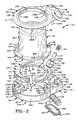
- FIG. 2is an exploded perspective view of the bottle security device.
- FIG. 3is a top plan view of the cap.
- FIG. 4is a sectional view taken on line 4 - 4 of FIG. 3 .
- FIG. 4Ais a sectional view taken on line 4 A- 4 A of FIG. 3 .
- FIG. 5is a bottom plan view of the cap.
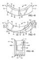
- FIG. 6is a bottom plan view of one of the securing members.
- FIG. 7is a top plan view of one of the securing members.
- FIG. 8is a sectional view of the locking member showing the teeth and the interior chamber.
- FIG. 9is a top plan view of the housing top member.
- FIG. 10is a rear elevational view of the housing top member.
- FIG. 11is a sectional view taken on line 11 - 11 of FIG. 10 .
- FIG. 12is a top plan view of the housing bottom member.
- FIG. 13is a sectional view taken on line 13 - 13 of FIG. 12 .
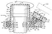
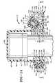
- FIG. 14is sectional view of the bottle security device on the bottle neck in the unsecured position.
- FIG. 15is a sectional view taken on line 15 - 15 of FIG. 14 . with the rectangular portion of the housing substantially omitted and the securing members shaded for clarity.
- FIG. 16is similar to FIG. 14 and shows the bottle security device in the secured position.
- FIG. 17is a sectional view taken on line 17 - 17 of FIG. 16 . with the rectangular portion of the housing substantially omitted and the securing members shaded for clarity.
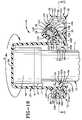
- FIG. 18is a sectional view similar to FIG. 14 showing the key unlocking the locking mechanism, rotation of the cap to move the securing members from the secured to the unsecured position.
- FIG. 19is a sectional view similar to FIG. 15 illustrating an alternate set of pivotable securing members in the unsecured position.
- FIG. 20is similar to FIG. 19 and shows the securing members pivoted to the secured position.
- the bottle security device of the present inventionis shown generally at 10 in FIG. 1 .
- Device 10is shown in FIG. 1 mounted on a bottle 12 having a neck 14 which includes a radially outwardly extending annular flange 16 ( FIG. 14 ) having a downwardly facing lower surface 17 .
- Device 10is securable to bottle neck 14 to prevent the theft of bottle 12 and its contents absent the use of a special key or damage to device 10 or bottle 12 .
- device 10includes a cap 18 , three securing members 20 A-C, a locking member 22 , a magnetically attractable cylinder 24 , a coil spring 26 , a housing top member 28 and a housing bottom member 30 which is secured to top member 28 when assembled to provide a housing having a front 29 and rear 31 .
- the housingfurther includes a bottom wall section 32 which is securable to bottom member 30 .
- the housingincludes a circular portion 33 and a generally rectangular portion 35 extending radially outwardly from circular portion 33 in a forward direction.
- An electronic article surveillance (EAS) tag 34is mounted within the housing for activating an alarm upon unauthorized removal of device 10 and bottle 12 from a secured area such as a store or the like.
- EASelectronic article surveillance
- Each of elements 18 , 20 , 22 , 28 , 30 and 32are formed of rigid materials, typically a rigid plastic.
- Cap 18includes a substantially flat circular top wall 36 and an annular sidewall 38 connected to top wall 36 and extending downwardly therefrom.
- cap 18may have an open cap configuration in which top wall 36 is eliminated or partially eliminated and sidewall 38 may be substantially shorter than shown in the figures.
- Sidewall 38is substantially cylindrical or tapers slightly to have a frustoconical configuration.
- Sidewall 38has an upper end 40 and a lower end 42 and defines therewithin a cavity 41 ( FIG. 4 ) having an entrance opening 43 adjacent lower end 42 whereby bottle neck 14 may be inserted through entrance opening 43 into cavity 41 .
- An annular flange 44is connected to and extends radially outwardly from sidewall 38 adjacent lower end 42 to a circular outer perimeter 45 .
- Sidewall 38 and flange 44are concentric about a vertically extending axis X ( FIGS. 4-5 ) passing through the center of top wall 36 and cavity 41 .
- a pair of arcuate slots 46 A and Bare formed in flange 44 extending from the top to the bottom thereof and having respective first and second circumferentially opposed ends 47 and 49 .
- Each slot 46is concentric about axis X and defines a circumferential width between first and second ends 47 and 49 which is approximately 60 degrees.
- the portion of flange 44 between first end 47 of slot 46 B and second end 49 of slot 46 Aalso has a circumferential width of approximately 60 degrees.
- a section 39 comprising a series of one-way locking teeth 48is formed atop flange 44 so that teeth 48 extend generally upwardly and are angled radially outwardly.
- Section 39 of locking teeth 48has first and second circumferentially opposed ends 51 and 53 defining therebetween a circumferential width which is approximately 60 degrees in the exemplary embodiment although this may vary.
- the segment of flange 44 extending between first end 51 of section 39 and second end 49 of slot 46 Bhas a circumferential width of approximately 60 degrees.
- each tooth 48has a base 55 and a tip 57 each of which is straight and defines a line defining an angle A with respect to a horizontal plane Y wherein angle A in the exemplary embodiment is approximately 30 degrees and typically in the range of 20 to 70 degrees, more typically from 25 to 60 degrees and usually from 30 to 45 degrees.
- Tip 57thus is angled from adjacent outer perimeter 45 of flange 44 upwardly and radially inwardly toward axis X.
- angle Amay vary from 0 to 90 degrees or any other suitable angle.
- flange 44includes three arcuate projections or ridges 50 A-C which extend downwardly from a flat annular wall 59 of flange 44 .
- Each ridge 50has an inner end 52 along an inner perimeter of flange 44 adjacent sidewall 38 and an outer end 54 adjacent and in communication with outer perimeter 45 of flange 44 .
- Each ridge 50spirals radially outwardly with respect to axis X from first end 52 to second end 54 .
- Slot 46 Ais disposed between ridges 50 A and 50 B extending from adjacent and radially outwardly of inner end 52 of ridge 50 B to adjacent and radially inwardly of outer end 54 of ridge 50 A.
- slot 46 Bis disposed between ridges 50 B and 50 C extending from adjacent and radially outwardly of inner end 52 of ridge 50 A to adjacent and radially inwardly of outer end 54 of ridge 50 C.
- Each ridge 50has a first inner cam surface 56 which faces generally radially inwardly and spirals outwardly with respect to axis X from first end 52 to second end 54 .
- each ridge 50has a second outer cam surface 58 which faces generally radially outwardly and spirals outwardly with respect to axis X from first end 52 to second end 54 .
- each inner cam surface 56has inner and outer terminal ends 61 A and 61 B respectively at inner and outer ends 52 and 54 of ridge 50 .
- each outer cam surface 58has inner and outer terminal ends 63 A and 63 B respectively at inner and outer ends 52 and 54 .
- the inner terminal ends 61 B of one of the ridges such as ridge 50 A and another adjacent ridge such as ridge 50 Cdefine therebetween a circumferential width or distance G which in the exemplary embodiment is approximately 120 degrees.
- Each ridge 50extends circumferentially a distance H or has a circumferential width or distance H defined between inner terminal end 63 A of outer cam surface 58 and outer terminal end 61 B of inner cam surface 56 of a given ridge 50 .
- Circumferential distance H in the exemplary embodimentis approximately 95 to 100 degrees.
- angle G and angle His angle J or circumferential distance J defined between an outer terminal end 61 B of an inner cam surface 56 of one ridge and the adjacent inner terminal end 63 A of an outer cam surface 58 of the closest adjacent ridge 50 , as shown with reference to ridges 50 C and 50 A.
- Distance Jis thus in the exemplary embodiment approximately 20 to 25 degrees.
- Each inner cam surface 56has a circumferential distance K defined between the inner and outer terminal ends 61 A and 61 B thereof.
- Distance K in the exemplary embodimentis approximately 65 to 75 degrees.
- outer cam surface 58has a circumferential distance L defined between the inner and outer terminal ends 63 A and 63 B thereof.
- each inner cam surface 56is an arc of a circle M which is shown in dashed lines in FIG. 5 and is concentric about a vertical axis P adjacent and parallel to vertical axis X. Axis P passes through top wall 36 of cap 18 and also through cavity 41 .
- each outer cam surface 58is an arc of a circle N which has a greater diameter than circle M and is also concentric about axis P.
- Flat annular wall 59has a flat horizontal lower surface including three crescent-shaped flat lower surfaces 65 A-C respectively between each adjacent pair of ridges 50 .
- Each of these downwardly facing crescent-shaped surfaces 65extends circumferentially from an inner cam surface 56 of one ridge 50 to an outer cam surface 58 of an adjacent ridge 50 and radially from the inner perimeter of flange 44 to outer perimeter 45 .
- Slots 46 A and 46 Bare respectively within two of these crescent-shaped regions so that slot 46 A extends from the top of flange 44 to crescent-shaped surface 65 A and slot 46 B extends from the top of flange 44 to crescent-shaped surface 65 C.
- each securing member 20has a first and second circumferentially opposed ends 60 and 62 , a convexly curved inner perimeter 64 extending from first end 60 to 62 and a convexly curved outer perimeter 66 extending from first end 60 to second end 62 .
- Inner and outer perimeters 64 and 66define arcs of respective circles which are substantially concentric about axis X when device 10 is assembled and members 20 are in the secured position ( FIG. 17 ).
- Securing member 20has parallel bottom and top surfaces 68 and 70 which are substantially flat and horizontal.
- Each end 60 and 62has a lower laterally-facing guide surface 72 and a laterally facing abutment surface 74 .
- the lower guide surfaces 72 on each end 60 and 62are parallel to one another.
- the abutment surfaces 74 on each end 60 and 62are approximately parallel to a radius of a circle which is concentric about axis X when device 10 is assembled and lie on such a radius in the secured position ( FIG. 17 ).
- Each securing member 20moves radially inwardly and outwardly as further described below so that when each securing member 20 is moved fully radially inwardly, the abutment surfaces 74 on first end 60 of one securing member 20 abuts the abutment surface 74 on a second end 62 of another securing member 20 .
- Each securing member 20includes a flat lower plate or wall 76 which defines bottom surface 68 .
- a substantially flat upper plate or wall 78is connected to and extends upwardly from lower plate 76 and is substantially parallel thereto.
- Each member 20has a tapered surface 79 which tapers radially upwardly and inwardly along inner perimeter 64 along lower and upper plates 76 and 78 .
- a straight groove 80 bounded by parallel guide surfaces 81is formed in lower plate 76 extending upwardly from bottom surface 68 parallel to guide surfaces 72 and aligned on a radius of a circle concentric about axis X when device 10 is assembled.
- Securing member 20may be formed without a groove 80 and corresponding guide surfaces or may be formed with additional grooves to provide additional guide surfaces if desired.
- each upper plate 78includes an inner arm 82 which extends along the full length of inner perimeter 64 and an outer arm 84 which extends along about half of outer perimeter 66 .
- Inner arm 82is a generally arcuate triangular shape and is wider adjacent first end 60 and narrows to substantially a point adjacent second end 62 adjacent inner perimeter 64 .
- Arm 84is also a curved triangular shape and is wider adjacent end 62 and narrows to a point adjacent the midpoint between first and second ends 60 and 62 at outer perimeter 66 .
- An arcuate groove 86is formed in upper plate 78 between inner and outer arms 82 and 84 extending downwardly from top surface 70 and defining an arc of a circle.
- Each groove 86spirals radially outwardly with respect to axis X from an inner terminal end 83 at abutment surface 74 of second end 62 adjacent inner perimeter 64 to an outer terminal end 85 adjacent first end 60 where it communicates with outer perimeter 66 .
- An inner cam surface 88 on first arm 82faces generally radially outwardly and bounds arcuate groove 86 so that it spirals radially outwardly in the same fashion.
- Inner cam surface 88has an inner terminal end 87 A at abutment surface 74 of second end 62 and an outer terminal end 87 B at outer perimeter 66 adjacent first end 60 .
- An outer cam surface 90faces generally radially inwardly and bounds the other side of groove 86 and thus spirals radially outwardly in the same manner to adjacent the midpoint between ends 60 and 62 .
- Outer cam surface 90has an inner terminal end 89 A at second end 62 and an outer terminal end 89 B at outer perimeter 66 near the midpoint between first and second ends 60 and 62 and slightly closer to first end 60 .
- Each groove 86has a constant width and thus the cam surfaces 88 and 90 bounding a given groove 86 curve in a parallel fashion.
- Each groove 86is configured to receive one of arcuate ridges 50 of flange 44 so that inner cam surface 56 of a respective ridge 50 slidably engages inner cam surface 88 , and outer cam surface 58 of each ridge 50 slidably engages outer cam surface 90 during rotation of cap 18 relative to the housing.
- Each ridge 50has a constant width and thus cam surface 56 and 58 bounding a given ridge 50 curve in parallel fashion.
- Inner and outer cam surfaces 56 and 58curve in a mating fashion respectively with inner and outer cam surfaces 88 and 90 .
- securing member 20may be formed with more than one groove similar to groove 86 to provide additional corresponding spiraling cam surfaces.
- additional projections or spiraling ridges similar to ridges 50may be formed on flange 44 of cap 18 to provide additional cam surfaces received in these additional grooves.
- a pair of upper guide surfaces 92 which are parallel to one anotherare formed respectively on arms 82 and 84 adjacent first and second ends 60 and 62 and extend upwardly vertically from a respective pair of tabs 94 at ends 60 and 62 .
- Each securing memberthus steps horizontally inwardly along an upper surface of tab 94 from lower guide surface 72 to upper guide surface 92 , which is parallel to surface 72 .
- locking member 22has upper and lower opposed ends 96 and 98 with a plurality of one-way locking teeth 100 formed at lower end 98 and extending downwardly therefrom for lockably engaging locking teeth 48 on flange 44 .
- Locking teeth 100 and locking teeth 48thus lockably engage one another to prevent rotation of cap 18 relative to the housing in one direction while allowing rotation in the opposite direction.
- Locking member 22is substantially rectangular as viewed from the side and substantially square as viewed from above and has a generally parallelepiped configuration.
- Member 22has a substantially flat inner side 102 ( FIG. 2 ), a substantially flat outer side 104 opposed thereto and a pair of opposed flat lateral sides 106 A and B.
- An interior chamberis formed in locking member 22 including a lower chamber 108 and an upper chamber 110 which has a greater diameter than that of lower chamber 108 .
- the interior chamberhas an entrance opening 112 and an annular lip 114 is formed between lower and upper chambers 110 .
- Lower chamber 108is configured for receiving cylinder 24 and upper chamber 110 is configured to receive spring 26 with a lower end of spring 26 abutting annular lip 114 for biasing locking member 22 to its locked position ( FIG. 16 ) with locking teeth 100 lockably engaging teeth 48 .
- Member 28includes a main wall 116 which has a circular wall portion 118 and a generally rectangular wall portion 120 extending radially outwardly therefrom.
- Circular wall portion 118is concentric about axis X and defines a circular hole or upper entrance opening 122 extending from the top to the bottom of main wall 116 .
- a wedge shaped portion 124is connected to and extends upwardly from rectangular wall portion 120 .
- Portion 124includes a front wall 126 which tapers radially upwardly and inwardly toward axis X to a rear wall 128 which tapers radially downwardly and inwardly therefrom toward axis X to main wall 116 at a location adjacent hole 122 .
- Portion 124further includes first and second space sidewalls 130 and 132 which are generally triangular and connected to each of front and rear walls 126 and 128 and extend upwardly from main wall 116 of rectangular portion 120 .
- a key alignment notch or indentation 134is formed in wedge shaped portion 124 extending laterally inwardly from first sidewall 130 .
- a pair of rear support posts 136 A and Bare connected to and extend downwardly from circular wall portion 118 and are spaced from one another to extend respectively through slots 46 A and 46 B of flange 44 when device 10 is assembled ( FIG. 15 ). Support posts 136 A and B provide additional strength between the top and bottom housing members but may be eliminated without otherwise altering the function of device 10 .
- flange 44may be formed without slots 46 for receiving such posts therethrough.
- a pair of front support posts 138 A and Blikewise extend downwardly from rectangular wall portion 120 on opposite sides of wedge shaped portion 124 .
- rear wall of wedge shaped portion 124has a flat inner surface 140 which is straight and tapers radially upwardly and outwardly away from axis X when device 10 is assembled at an angle B relative to horizontal plane Y wherein angle B is in the exemplary embodiment approximately 60 degrees, typically in the range of 20 to 70 degrees, more typically from 30 to 65 degrees and usually from 45 to 60 degrees.
- angle Bmay be any suitable angle.
- An interior wall 142is connected to and extends downwardly from front wall 126 and is spaced forward from rear wall 128 .
- Interior wall 142has a rear upwardly extending surface 144 which is substantially vertical.
- Front wall 126angles radially inwardly and upwardly to define an angle C with horizontal plane Y which is in the exemplary embodiment about 30 degrees and thus at a right angle to surface 140 .
- Angle Cis the same as angle A and falls within the ranges noted with reference to angle A.
- a downwardly opening cavity 146is formed in wedge shaped portion 124 and bounded by the inner surface of front wall 126 and surfaces 140 and 144 .
- Bottom member 30includes a circular portion 148 defining a circular interior chamber 149 and a generally rectangular portion 150 defining a generally rectangular interior chamber 151 .
- Member 30includes a bottom wall which includes a circular bottom wall portion 152 and a front bottom wall portion 154 extending radially forward from portion 152 .
- a circular hole or lower entrance opening 156is formed in circular bottom wall portion 152 and communicates with interior chamber 149 , as does entrance opening 122 of housing top member 28 when device 10 is assembled.
- a substantially rectangular hole 158is formed in the bottom of rectangular portion 150 which receives bottom wall section 32 ( FIG. 2 ) when secured thereto ( FIG. 14 ).
- Circular portion 148includes a circular sidewall 160 having a circular inner surface 161 bounding and circumscribing interior chamber 149 .
- Sidewall 160includes an interior segment or arc 162 the outer surface of which bounds rectangular interior chamber 151 .
- Rectangular portion 150includes a front wall 164 and first and second lateral sidewalls 166 and 168 connected to front wall 164 and circular sidewall 160 with interior segment 162 extending therebetween.
- Ledges 170 and 172are formed on rectangular portion 150 respectively along sidewalls 166 and 168 .
- Three straight ridges 174 A-C( FIG. 12 ) having parallel guide surfaces 175 are connected to and extend upwardly from bottom wall portion 152 , extend radially inwardly from sidewall 160 to the inner perimeter of bottom wall 152 which bounds hole 156 and are elongated horizontally along a radius of a circle which is concentric about axis X. Ridges 174 are circumferentially equally spaced from one another so that each adjacent pair of ridges 174 defines therebetween an angle D which is approximately 120 degrees.
- Three triangular guides 176 A-Care connected to and extend upwardly from bottom wall 152 and radially inwardly from sidewall 160 .
- Guides 176are equally spaced from one another circumferentially with each of guides 176 positioned midway between an adjacent pair of ridges 174 .
- Each guide 176is a substantially flat horizontal plate having first and second straight lower guide surfaces 178 and 180 which are connected to and extend inwardly from sidewall 160 toward one another to terminate adjacent the inner perimeter of bottom wall 152 which bounds hole 156 .
- Guide surfaces 178 and 180 of each guide 176define therebetween an angle E which in the exemplary embodiment is approximately 120 degrees.
- the guide surface 178 of each guide 176is parallel to the guide surface 180 of an adjacent guide 176 and also parallel to surfaces 175 of the straight guide 174 disposed between said surfaces 178 and 180 .
- These parallel surfaces 178 and 180 of the respective guides 176define therebetween a channel in which the respective securing member 20 is slidably received.
- Each arm 182 A-C( FIG. 12 ) are connected to sidewall 160 and extend radially inwardly therefrom and respectively over guides 176 A-C.
- Each arm 182is also a substantially flat horizontal plate seated on a respective guide 176 and includes a pair of overhangs 184 which extend outwardly over and beyond guide surfaces 178 and 180 of guide 176 .
- First and second straight upper guide surfaces 186 and 188are formed on a respective overhangs 184 parallel to and respectively adjacent guide surfaces 178 and 180 .
- Second guide surface 188is connected to and extends inwardly from sidewall 160 .
- first guide surface 186is on a free end of arm 182 which is spaced radially inwardly from inner surface 161 of sidewall 160 .
- An arcuate outer surface 190 on each arm 182faces generally radially outwardly and spirals radially inwardly relative to axis X from adjacent inner surface 161 of sidewall 160 to guide surface 186 at the free end of arm 182 .
- Outer surface 190 and inner surface 161 of sidewall 160thus define therebetween a curved triangular groove 192 bounded by the upper surface of a respective guide 176 .
- An arcuate inner surface 191 on each arm 182faces generally radially inwardly and spirals radially inwardly relative to axis X from guide surface 188 to guide surface 186 with a parallel curvature to outer surface 190 .
- a rear post-receiving hole 194is formed in each of arms 182 A and 182 B extending downwardly from the upper surfaces thereof for respectively receiving therein the lower ends of support posts 136 A and 136 B of top member 28 when device 10 is assembled ( FIG. 15 ).
- a pair of front post-receiving holes 196are spaced from one another adjacent and external to interior segment 162 of sidewall 160 respectively inwardly of and adjacent lateral sidewalls 166 and 168 for respectively receiving the lower ends of support posts 138 A and 138 B when device 10 is assembled.
- a substantially flat tapered guide wall 198( FIGS. 12-13 ) is connected to interior segment 162 of sidewall 160 and tapers radially upwardly and outwardly relative to axis X within rectangular interior chamber 151 .
- Wall 198has a flat guide surface 200 tapering in the same manner.
- a pair of spaced lateral walls 202are connected to guide wall 198 and extend radially inwardly therefrom to connect to interior segment 162 .
- Surface 200 and horizontal plane Ydefine therebetween an angle F which in the exemplary embodiment is approximately 60 degrees. Angle F is the same as angle B ( FIG. 11 ) and falls within the same ranges described with reference to angle B.
- bottom wall section 32includes a generally flat rectangular wall 204 , a first tab 206 extending laterally outwardly from one end thereof and a second tab 208 extending upwardly from the opposite end thereof.
- tab 206is inserted from below into rectangular interior chamber 151 ( FIG. 12 ) and seated atop ledge 170 and tab 208 is pushed upwardly into chamber 151 to form a snap fit connection with ledge 172 so that bottom wall section 32 is non-removably secured to bottom member 30 to bound the bottom of interior chamber 151 .
- FIG. 14shows a sectional view of bottle security device 10 when assembled in the unsecured position.
- Securing members 20are spread apart far enough so that the inner perimeters 64 thereof have a greater diameter than that of flange 16 of bottle neck 14 so that flange 16 and neck 14 have been inserted upwardly through entrance opening 156 and the opening formed between members 20 into cavity 41 of cap 18 with flange 16 disposed upwardly of upper surfaces of 70 of members 20 .
- EAS tag 34is disposed within rectangular interior chamber 151 .
- Top member 28is secured to the top of bottom member 30 typically by ultrasonic welding although another fastening mechanism may be used such as glue, fasteners such as screws and so forth.
- top wall 36 and side wall 38 of cap 18Prior to the connection of top member 28 to bottom member 30 , top wall 36 and side wall 38 of cap 18 are inserted upwardly through entrance opening 122 of top member 28 so that lower end 42 of side wall 38 is disposed in opening 122 and slidably engages circular wall portion 118 during relative rotation.
- Flange 44 of cap 18is disposed within circular interior chamber 149 ( FIG. 13 ) with the upper surface of flat annular wall 59 slidably engaging the lower surface of circular wall portion 118 during rotation and the lower crescent shaped surfaces 65 of wall 59 seated on and slidably engaging the upper surfaces 70 of securing members 20 during rotation of cap 18 .
- Outer perimeter 45 of flange 44is closely adjacent or slidably engages inner surface 161 ( FIG.
- each securing member 20 adjacent inner perimeter 64is disposed directly below side wall 38 of cap 18 in the unsecured position.
- Inner perimeters 64 of the securing members 20lie on a circle of a diameter which is substantially the same as that of opening 156 .
- Tapered guide wall 198extends upwardly into cavity 146 with its upper end abutting inner surface 144 of interior wall 142 adjacent its connection to front wall 126 .
- FIG. 15is a sectional view of device 10 with securing members 20 (shaded) in the unsecured position. Ridges 50 A-C are shown within the spiraling grooves 86 of the respective securing members 20 A-C. Securing members 20 are positioned with outer perimeters 66 abutting inner surface 161 of sidewall 160 and thus lie on a circular path concentric about axis X. Outer ends 54 of ridges 50 are at outer ends 85 of grooves 86 and abut or are closely adjacent inner surface 161 outside of and circumferentially spaced from respective grooves 192 .
- Inner ends 52 of ridges 50are adjacent respective guides 176 with outer cam surfaces 58 adjacent ends 52 slidably engaging inner surfaces 191 of respective arms 182 .
- Each inner end 52 of a ridge 50is thus positioned radially inwardly of and adjacent a respective arm 182 and at the same height thereof.
- the inner ends 52 of respective ridges 50 A and 50 Bare likewise adjacent and spaced radially inwardly of posts 136 B and 136 A, which are disposed at the first ends 47 of respective slots 46 B and 46 A in the unsecured position of securing members 20 .
- the inner ends 52 of each of ridges 50also abuts one of abutment surfaces 74 adjacent a first end 60 of a respective securing member 20 .
- the abutment surface 74 on a second end 62 of an adjacent securing member 20is parallel to and spaced from the abutment surface 74 contacted by said first end 52 .
- Each lower plate 76 of a respective member 20is positioned within the channel defined between a pair of parallel guide surfaces 178 and 180 with surfaces 72 on ends 60 and 62 of member 20 slidably engaging surfaces 178 and 180 .
- Tabs 94are positioned beneath overhangs 184 and surfaces 92 slidably engage surfaces 186 and 188 of a respective pair of adjacent arms 184 .
- the upper surfaces of tabs 94also respectively are closely adjacent or slidably engage the lower surfaces of overhangs 184 , which further substantially eliminate vertical movement of each securing member 20 , which thus slides linearly along a horizontal path.
- Each ridge 174is received within a groove 80 ( FIG. 17 ) of a respective securing member 20 with surfaces 81 ( FIG. 17 ) of securing member 20 slidably engaging guide surfaces 175 of ridge 174 .
- Bottom surface 68 ( FIG. 14 )slidably engages the upper surface of circular bottom wall portion 152 .
- the sliding engagement between the various guide surfacesguides the sliding movement of each member 20 radially inwardly from the unsecured position ( FIGS. 14-15 ) to the secured position ( FIGS. 16-17 ) and radially outwardly in reverse. More particularly, each securing member 20 slides in a linear fashion parallel to surfaces 81 and 175 and the radius along which the respective ridge 174 and groove 80 lies.
- cap 18is rotated (Arrows Q in FIG. 16 ) so that ridges 50 rotate (Arrows R in FIG. 17 ) relative to the housing and the outer ends 54 of ridges 50 slidably engage inner surface 161 of sidewall 160 and move into respective grooves 192 between arms 184 and sidewall 160 .
- Each inner cam surface 56 of a respective ridge 50 adjacent outer end 54matingly engages outer surface 190 as outer end 54 rotates into slot 192 .
- Each inner end 52 of a respective ridge 50moves circumferentially within a respective slot 86 away from the abutment surface 74 which it engaged in the unsecured position shown in FIG. 15 .
- the rotational movement of cap 18causes inner cam surfaces 56 of ridges 50 to respectively slidably engage inner cam surfaces 88 of securing members 20 to force members 20 to slide linearly radially inwardly (arrows S) to the secured position of FIGS. 16 and 17 from the unsecured position of FIGS. 14 and 15 .
- cap 18During the rotation of cap 18 , the position of posts 136 A and B respectively shift to the second ends 49 of respective slots 46 A and 46 B. Outer ends 54 of ridges 50 A and 50 C are respectively adjacent and spaced radially outwardly of posts 136 and second ends 49 of slots 46 .
- the rotational movement of cap 18 to move members 20 from the unsecured position to the secured positionmay be accomplished without unlocking locking member 22 due to the one-way nature of locking teeth 100 and 48 .
- locking member 22After rotation to the secured position, locking member 22 is biased by spring 26 to the locked position with teeth 100 thereof lockably engaging teeth 48 on flange 44 of cap 18 , as shown in FIG. 16 .
- a key member 210( FIG. 18 ) including a magnet 212 is first used to unlock device 10 .
- Key member 210includes an alignment tab 214 which is receivable within key alignment notch 134 ( FIGS. 2 , 9 ) on wedge shaped section 124 to align magnet 212 with magnetically attractable cylinder 24 in order to attract cylinder 24 toward the magnet 212 .
- Cylinder 24is secured to locking member 22 so that locking member 22 is likewise moved (Arrow T) toward magnet 212 to overcome the spring bias of spring 26 so that locking teeth 100 are disengaged from locking teeth 48 , thus allowing cap 18 to rotate in a direction (Arrow U ) opposite that shown in FIG. 16 (Arrows Q).
- Rotation in this opposite directioncauses outer ends 54 of ridges 50 to move circumferentially along a circular path out of grooves 192 with outer cam surfaces 58 slidably engaging outer cam surfaces 90 of members 20 to force members 20 to move radially outwardly in a linear fashion from the secured position of FIGS. 16 and 17 to the unsecured position of FIGS. 14 and 15 .
- Inner perimeters 64 of securing member 20thus move outwardly beyond the outer surface of flange 16 so that bottle neck 14 may be removed from within cavity 41 of cap 18 .
- locking member 22is spring biased to the locked position
- securing members 20are not spring biased to the unsecured position. This prevents securing members 20 from automatically moving to the unsecured position if locking member 22 is moved even momentarily to its unlocked position.
- the housing of device 10is also configured to make it more difficult for locking member 22 to become dislodged from its locking position in an attempt to defeat device 10 .
- locking memberswhich are magnetically attractable move in a horizontal direction radially outwardly from a locked position to an unlocked position.
- the securing membersmay be spring biased to their unsecured position, in the exemplary embodiment the securing members do not automatically move to the unsecured position when the locking member is in the unlocked position.
- locking member 22moves to the unlocked position not in a radially outwardly horizontal direction (perpendicular to axis X) but rather radially upwardly and outwardly in a linear fashion (Arrow T) at an angle to the horizontal. While this angle may vary, it is shown in the exemplary embodiment to move at an angle of approximately 60 degrees relative to the horizontal, being guided by guide surfaces 140 and 200 which are so angled. The angle at which locking member 22 moves is thus the same as angle B ( FIG. 11 ) and falls within the ranges noted with respect thereto.
- FIGS. 19 and 20show an alternate embodiment of pivotable securing members 20 D-F.
- Securing members 20 D-Fare respectively pivotally mounted on pivots 218 which are secured to circular bottom wall portion 152 and extend into interior chamber 149 .
- a groove or slot 86 Ais formed in each of securing members 20 D-F and spirals radially outwardly in the same manner as grooves 86 formed in securing members 20 A-C.
- Each of securing members 20 D-Fthus includes cam surfaces 88 A and 90 A which spiral outwardly in the same manner as cam surfaces 88 and 90 of securing members 20 A-C.
- cam projections shown as generally cylindrical pins 220are received respectively in each of slots 86 A for camming engagement with the respective cam surfaces 88 A and 90 A. Pins 220 thus are connected to and project downwardly from annular flange 44 of cap 18 instead of ridges 50 .
- camming pins 220rotate along with cap 18 as indicated by Arrows V in FIG. 20 to slidably engage respective cam surfaces 88 A to force the respective securing members 20 D-F pivotally inward about pivots 218 as indicated at Arrows W from the unsecured position of FIG. 19 to the secured position of FIG. 20 .
- securing members 20 D-F in the unsecured position of FIG. 19are spaced radially outwardly of the outer circumference of flange 16 of bottle neck 14 and pivot inwardly beneath flange 16 radially inward of its outer circumference in the secured position of FIG. 20 in order to prevent removal of the bottle securing device from the bottle neck.
- bottle security device 10provides several advantageous features and new structures within the art which are configured to prevent the theft of bottle 12 or the contents thereof without the use of a special key member or without breaking bottle 12 or damaging device 10 .
Landscapes
- Closures For Containers (AREA)
Abstract
Description
Claims (20)
Priority Applications (3)
| Application Number | Priority Date | Filing Date | Title |
|---|---|---|---|
| US12/001,691US7866497B2 (en) | 2007-12-12 | 2007-12-12 | Bottle security device |
| PCT/US2008/013052WO2009075723A1 (en) | 2007-12-12 | 2008-11-24 | Bottle security device |
| EP08860044.0AEP2231489B1 (en) | 2007-12-12 | 2008-11-24 | Bottle security device |
Applications Claiming Priority (1)
| Application Number | Priority Date | Filing Date | Title |
|---|---|---|---|
| US12/001,691US7866497B2 (en) | 2007-12-12 | 2007-12-12 | Bottle security device |
Publications (2)
| Publication Number | Publication Date |
|---|---|
| US20090152230A1 US20090152230A1 (en) | 2009-06-18 |
| US7866497B2true US7866497B2 (en) | 2011-01-11 |
Family
ID=40751831
Family Applications (1)
| Application Number | Title | Priority Date | Filing Date |
|---|---|---|---|
| US12/001,691Active2029-04-17US7866497B2 (en) | 2007-12-12 | 2007-12-12 | Bottle security device |
Country Status (3)
| Country | Link |
|---|---|
| US (1) | US7866497B2 (en) |
| EP (1) | EP2231489B1 (en) |
| WO (1) | WO2009075723A1 (en) |
Cited By (10)
| Publication number | Priority date | Publication date | Assignee | Title |
|---|---|---|---|---|
| US20090212001A1 (en)* | 2008-02-21 | 2009-08-27 | Mary Clemente | Jurado cap assembly |
| US20130169409A1 (en)* | 2011-12-30 | 2013-07-04 | Hsin-Pei Chang | Anti-counterfeiting article and method thereof |
| US20130334162A1 (en)* | 2012-06-16 | 2013-12-19 | Mike Salisbury | Adjustable cap |
| USD727191S1 (en) | 2013-12-04 | 2015-04-21 | Xiao Hui Yang | EAS tag for bottles |
| US20150158659A1 (en)* | 2011-02-04 | 2015-06-11 | S.C. Johnson & Son, Inc. | Attachment mechanism for a container |
| USD742773S1 (en) | 2013-09-23 | 2015-11-10 | Wg Security Products | EAS tag for bottles |
| US9311797B2 (en) | 2010-04-05 | 2016-04-12 | Wg Security Products | EAS tag for bottles |
| US9472073B2 (en) | 2013-11-21 | 2016-10-18 | Wg Security Products, Inc. | EAS tag for bottles |
| US10872482B1 (en) | 2017-11-22 | 2020-12-22 | Alexander Montgomery Colton | Personalized lid for prescription bottles |
| US10973320B2 (en)* | 2018-11-29 | 2021-04-13 | Compal Electronics, Inc. | Wine bottle fixing device |
Families Citing this family (13)
| Publication number | Priority date | Publication date | Assignee | Title |
|---|---|---|---|---|
| EP2496781A2 (en)* | 2009-11-02 | 2012-09-12 | Checkpoint Systems, Inc. | Adjustable dual loop cable security device |
| US9206628B2 (en) | 2010-03-12 | 2015-12-08 | Checkpoint Systems, Inc. | Security device |
| US8887541B2 (en) | 2010-03-12 | 2014-11-18 | Checkpoint Systems, Inc. | Security device |
| US8525675B2 (en) | 2010-03-12 | 2013-09-03 | Checkpoint Systems, Inc. | Security device |
| WO2014134292A1 (en)* | 2013-02-27 | 2014-09-04 | Michael Norman | Tag housing assembly for attachment to a bottle neck |
| CN203499390U (en)* | 2013-10-08 | 2014-03-26 | 广州维琼兰科技有限公司 | Wind bottle anti-theft protective device |
| ES2727449T3 (en)* | 2014-12-18 | 2019-10-16 | Enneffe S R L | Anti-theft and safety mechanisms for bottles |
| CN111108254B (en)* | 2017-07-28 | 2022-09-16 | 关卡系统股份有限公司 | A locking slider safety device |
| CN109229705B (en)* | 2018-08-15 | 2023-10-03 | 四川宜宾五粮液精美印务有限责任公司 | Environment-friendly anti-counterfeiting packaging box |
| HUP1800372A1 (en)* | 2018-11-05 | 2020-05-28 | Shopguard Kft | Article surveillance tag |
| GB2580933A (en)* | 2019-01-30 | 2020-08-05 | YASIN Omar | Security device for bottles |
| JP7629731B2 (en)* | 2019-09-20 | 2025-02-14 | キャリア コーポレイション | Method and system for locking and unlocking - Patents.com |
| KR102715904B1 (en)* | 2022-07-21 | 2024-10-11 | 이진행 | Locking stopper and container having the same |
Citations (81)
| Publication number | Priority date | Publication date | Assignee | Title |
|---|---|---|---|---|
| US445755A (en) | 1891-02-03 | Bottle-lock | ||
| US654533A (en) | 1899-12-11 | 1900-07-24 | Alfred Garner | Stopper-fastener. |
| US770387A (en) | 1904-09-20 | Fruit-jar | ||
| US783885A (en) | 1904-10-24 | 1905-02-28 | Harry C Mcdougall | Bottle-seal. |
| US809213A (en) | 1905-03-20 | 1906-01-02 | Frederick M Osgood | Means for sealing bottles. |
| US833446A (en) | 1906-03-01 | 1906-10-16 | Paul A Degener | Bottle-locking mechanism. |
| US880723A (en) | 1907-03-21 | 1908-03-03 | James M Cumming | Bottle-closure. |
| US1343962A (en) | 1919-11-16 | 1920-06-22 | Clark Hudson | Safety-lock for bottles or the like |
| US1937295A (en) | 1933-01-03 | 1933-11-28 | Napier Co | Bottle lock |
| US2418039A (en) | 1946-01-04 | 1947-03-25 | Wilburt W Mays | Bottle closure retainer |
| GB677311A (en) | 1950-09-27 | 1952-08-13 | Abraham Aladar Brody | Safety means for poison bottles and the like |
| US3025990A (en) | 1959-12-11 | 1962-03-20 | Sparkle Top Corp | Plastic closure members for champagne bottles |
| US3102651A (en)* | 1960-10-03 | 1963-09-03 | Arthur H Boese | Flow control neck or head |
| DE2121739A1 (en) | 1971-05-03 | 1972-11-09 | Metallwerke Adolf Hopf KG, 8860 Nördlingen | Safety cap for vessels with a neck |
| DE2307205A1 (en) | 1973-02-14 | 1974-08-22 | Neuro Plast Gmbh & Co Kg | SECURITY BOTTLE CAP |
| US3837518A (en) | 1972-11-30 | 1974-09-24 | Sunbeam Plastics Corp | Tamper-proof and child-proof medicine bottle or the like |
| US3843006A (en) | 1971-12-25 | 1974-10-22 | Takeda Chemical Industries Ltd | Safety bottle cap |
| US3863798A (en) | 1972-11-06 | 1975-02-04 | Kanebo Ltd | Push-button-type cap for container |
| US3893582A (en) | 1973-10-05 | 1975-07-08 | Continental Can Co | Child proof closure |
| AR203305A1 (en) | 1974-09-18 | 1975-08-29 | Briti H | SAFETY LID FOR BOTTLES, BOTTLES AND THE LIKE |
| US3913769A (en)* | 1974-12-20 | 1975-10-21 | Suwa Seikosha Kk | Safety locking cap |
| US3944102A (en) | 1972-04-05 | 1976-03-16 | Hermann Grau | Safety screw closure |
| US3947930A (en) | 1974-10-30 | 1976-04-06 | I. D. Engineering, Inc. | Anti-theft fastening device and tool for releasing same |
| US3950917A (en) | 1973-03-07 | 1976-04-20 | American Hospital Supply Corporation | Method of opening a double screw cap system for sterile medical container |
| US4056209A (en) | 1977-03-23 | 1977-11-01 | W.P. Energy Technology Systems | Medication bottle having a safety cap |
| AR212291A1 (en) | 1977-10-13 | 1978-06-15 | Cygon Sa C I F I | CLOSURE FOR PACKAGING OF SPECIAL PRODUCTS |
| AR214228A1 (en) | 1978-02-10 | 1979-05-15 | Klochko C | THREADABLE SAFETY LID FOR BOTTLES AND THE LIKE |
| US4260067A (en) | 1978-10-20 | 1981-04-07 | Roman Andruchiw | Safety closure |
| US4279353A (en) | 1977-04-23 | 1981-07-21 | Zensho Honma | Plastic bottle cap |
| GB2082552A (en) | 1980-08-18 | 1982-03-10 | Johnsen Jorgensen Plastics Ltd | Child resistant container and closure assemblies |
| US4364483A (en)* | 1981-02-02 | 1982-12-21 | Erich Golde | Child proof screw cap |
| AR227988A1 (en) | 1982-10-07 | 1982-12-30 | Bonaventura Eduardo Nestor | SAFETY COVER FOR CONTAINERS |
| DE3211387A1 (en) | 1982-03-27 | 1983-09-29 | Johannes 2082 Uetersen Hebbelmann | Safety closure, especially for medicine bottles |
| US4570810A (en) | 1985-03-15 | 1986-02-18 | Sunbeam Plastics Corporation | Cap with tamper indicating band |
| FR2586231A1 (en) | 1985-08-13 | 1987-02-20 | Begouen Jean Paul | Stopper for bottles or the like incorporating opening means with a safety lock |
| US4710752A (en) | 1986-08-08 | 1987-12-01 | Pitney Bowes Inc. | Apparatus and method for detecting a magnetic marker |
| FR2608285A2 (en) | 1986-11-03 | 1988-06-17 | Bouan Bruno | Anti-theft device |
| US4775061A (en) | 1987-11-23 | 1988-10-04 | Coote David J | Safety bottle cap |
| US4796768A (en) | 1988-01-26 | 1989-01-10 | Stuckey William C | Lockable closure cap |
| WO1989007076A1 (en) | 1988-01-26 | 1989-08-10 | Stuckey William C | Lockable closure cap |
| US4944075A (en) | 1989-09-18 | 1990-07-31 | Security Tag Systems, Inc. | Detrimental-substance-containing theft-deterrent device |
| EP0385540A1 (en) | 1989-02-24 | 1990-09-05 | N.V. Nederlandsche Apparatenfabriek NEDAP | Detection label for an anti-shop-lifting system |
| US4960218A (en)* | 1989-10-24 | 1990-10-02 | Nippon Sanso Kabushiki Kaisha | Plug body for a liquid container |
| WO1991004201A1 (en) | 1989-09-12 | 1991-04-04 | Pehr Harold T | Captive key release closure structure |
| WO1992000173A1 (en) | 1990-06-29 | 1992-01-09 | Slegten Jacobus Hermanus Josep | Insect control |
| US5085332A (en) | 1991-04-11 | 1992-02-04 | Gettig Technologies, Inc. | Closure assembly |
| US5114029A (en) | 1991-07-10 | 1992-05-19 | Merck & Co., Inc. | Child resistant bottle closure assemblage |
| WO1992012067A1 (en) | 1990-12-27 | 1992-07-23 | Pehr Harold T | Captive key release closure structure |
| EP0522679A2 (en) | 1991-06-26 | 1993-01-13 | Alpha Enterprises, Inc. | Cassette security container |
| US5261548A (en)* | 1989-02-03 | 1993-11-16 | Senetics, Inc. | Indicator cap for use with threaded or bayonet lug container |
| US5269429A (en) | 1990-05-15 | 1993-12-14 | Robert Finke Gmbh & Co. Kg | Closure cap for infusion or transfusion bottles |
| US5303835A (en) | 1992-06-24 | 1994-04-19 | Habley Medical Technology Corporation | Lyophilization cap and method |
| WO1994008867A1 (en) | 1992-10-19 | 1994-04-28 | Hartek S.A. | Device for the identification and locking of a bottle |
| AR246914A1 (en) | 1991-05-10 | 1994-10-31 | Munoz Jorge Omar | Safety top for packages with a screw-on neck. |
| US5386924A (en) | 1994-05-10 | 1995-02-07 | Flinta; Frank J. | Cap for gas outlet nozzles |
| US5431293A (en) | 1994-03-14 | 1995-07-11 | Piron; Ludwig A. | Child-proof container closure and locking system |
| US5433329A (en) | 1994-09-23 | 1995-07-18 | Primary Delivery Systems, Inc. | Child-resistant cap with independent open and close ratchet sets |
| US5462186A (en) | 1994-08-02 | 1995-10-31 | The Coca Cola Company | Cam follower closure on container with cam track finish |
| US5464109A (en) | 1994-08-15 | 1995-11-07 | Greenwald; Kenneth | Lockable bottle cap retainer |
| EP0687635A1 (en) | 1994-06-17 | 1995-12-20 | Werner & Mertz GmbH | Bottle- or canister closure |
| US5519381A (en) | 1992-11-18 | 1996-05-21 | British Technology Group Limited | Detection of multiple articles |
| WO1997000819A1 (en) | 1995-06-20 | 1997-01-09 | Fors France S.A. | Theft preventing device, particularly for bottles |
| US5602530A (en) | 1993-03-12 | 1997-02-11 | Mw International Ltd. | Anti-theft device for bottles |
| US5615788A (en) | 1995-08-10 | 1997-04-01 | Larguia; Constancio | Container safety cap |
| US5638970A (en) | 1989-02-03 | 1997-06-17 | Senetics, Inc. | Child-resistant indicator cap |
| US5678712A (en) | 1995-05-26 | 1997-10-21 | Owens-Illnois Closure Inc. | Child resistant reminder closure |
| US5749484A (en) | 1995-09-22 | 1998-05-12 | Rieke Corporation | Tamper-evident child-resistant closure |
| US5769252A (en) | 1996-12-05 | 1998-06-23 | Volpe And Koenig, P.C. | Container closure which converts from a child resistant to a non-child resistant configuration |
| US5960972A (en) | 1996-11-15 | 1999-10-05 | Constancio Larguia, Sr. | Container cap with interlocked safety closure |
| WO1999067149A1 (en) | 1998-06-24 | 1999-12-29 | Alpha Enterprises, Inc. | Bottle security device |
| US6382416B1 (en) | 2000-06-27 | 2002-05-07 | Kathy S. Gainey | Medicine safety storage system |
| US20030121879A1 (en)* | 2002-01-02 | 2003-07-03 | Erie Plastics Corporation | Anti-leak dust cover and closure used therewith |
| US20030168456A1 (en) | 2002-03-06 | 2003-09-11 | Alessandro Tomasella | Closure device particularly for bottles and/or containers |
| US6631629B1 (en) | 2001-07-30 | 2003-10-14 | Arthur Fuss | Anti-theft product tag with ball clutch |
| US20040016269A1 (en) | 2002-07-29 | 2004-01-29 | Johan Skjellerup | Security tag assembly |
| US20040040962A1 (en)* | 2002-09-04 | 2004-03-04 | Andy Bielecki | Insulated beverage container and lid assembly |
| US20040060892A1 (en) | 2002-09-30 | 2004-04-01 | Heston Jeffrey C | Closure having taper-evidencing label |
| US20040182814A1 (en) | 2001-05-02 | 2004-09-23 | Udo Suffa | Closure cap cooperating with a bottle container |
| US6912878B2 (en) | 2003-02-24 | 2005-07-05 | Alpha Security Products, Inc. | Bottle security device |
| US20060170559A1 (en)* | 2004-12-22 | 2006-08-03 | Alpha Security Products, Inc. | Bottle security device |
| US7100784B2 (en) | 2003-07-25 | 2006-09-05 | Alpha Security Products, Inc. | Bottle security device |
Family Cites Families (4)
| Publication number | Priority date | Publication date | Assignee | Title |
|---|---|---|---|---|
| GB499116A (en)* | 1938-03-19 | 1939-01-18 | Ottokar Bondy | A device for retaining or securing bottle stoppers |
| US3842006A (en)* | 1970-05-22 | 1974-10-15 | Ethyl Corp | Thermoplastic filter media and filtering process |
| US3858740A (en)* | 1973-05-04 | 1975-01-07 | Pierre J Lestaevel | Locking device for containers |
| AU2006248722B2 (en)* | 2005-05-20 | 2011-11-03 | Premier Security Products Limited | Bottle cap protector |
- 2007
- 2007-12-12USUS12/001,691patent/US7866497B2/enactiveActive
- 2008
- 2008-11-24WOPCT/US2008/013052patent/WO2009075723A1/enactiveApplication Filing
- 2008-11-24EPEP08860044.0Apatent/EP2231489B1/ennot_activeNot-in-force
Patent Citations (90)
| Publication number | Priority date | Publication date | Assignee | Title |
|---|---|---|---|---|
| US445755A (en) | 1891-02-03 | Bottle-lock | ||
| US770387A (en) | 1904-09-20 | Fruit-jar | ||
| US654533A (en) | 1899-12-11 | 1900-07-24 | Alfred Garner | Stopper-fastener. |
| US783885A (en) | 1904-10-24 | 1905-02-28 | Harry C Mcdougall | Bottle-seal. |
| US809213A (en) | 1905-03-20 | 1906-01-02 | Frederick M Osgood | Means for sealing bottles. |
| US833446A (en) | 1906-03-01 | 1906-10-16 | Paul A Degener | Bottle-locking mechanism. |
| US880723A (en) | 1907-03-21 | 1908-03-03 | James M Cumming | Bottle-closure. |
| US1343962A (en) | 1919-11-16 | 1920-06-22 | Clark Hudson | Safety-lock for bottles or the like |
| US1937295A (en) | 1933-01-03 | 1933-11-28 | Napier Co | Bottle lock |
| US2418039A (en) | 1946-01-04 | 1947-03-25 | Wilburt W Mays | Bottle closure retainer |
| GB677311A (en) | 1950-09-27 | 1952-08-13 | Abraham Aladar Brody | Safety means for poison bottles and the like |
| US3025990A (en) | 1959-12-11 | 1962-03-20 | Sparkle Top Corp | Plastic closure members for champagne bottles |
| US3102651A (en)* | 1960-10-03 | 1963-09-03 | Arthur H Boese | Flow control neck or head |
| DE2121739A1 (en) | 1971-05-03 | 1972-11-09 | Metallwerke Adolf Hopf KG, 8860 Nördlingen | Safety cap for vessels with a neck |
| US3843006A (en) | 1971-12-25 | 1974-10-22 | Takeda Chemical Industries Ltd | Safety bottle cap |
| US3944102A (en) | 1972-04-05 | 1976-03-16 | Hermann Grau | Safety screw closure |
| US3863798A (en) | 1972-11-06 | 1975-02-04 | Kanebo Ltd | Push-button-type cap for container |
| US3837518A (en) | 1972-11-30 | 1974-09-24 | Sunbeam Plastics Corp | Tamper-proof and child-proof medicine bottle or the like |
| DE2307205A1 (en) | 1973-02-14 | 1974-08-22 | Neuro Plast Gmbh & Co Kg | SECURITY BOTTLE CAP |
| US3950917A (en) | 1973-03-07 | 1976-04-20 | American Hospital Supply Corporation | Method of opening a double screw cap system for sterile medical container |
| US3893582A (en) | 1973-10-05 | 1975-07-08 | Continental Can Co | Child proof closure |
| AR203305A1 (en) | 1974-09-18 | 1975-08-29 | Briti H | SAFETY LID FOR BOTTLES, BOTTLES AND THE LIKE |
| US3947930A (en) | 1974-10-30 | 1976-04-06 | I. D. Engineering, Inc. | Anti-theft fastening device and tool for releasing same |
| US3913769A (en)* | 1974-12-20 | 1975-10-21 | Suwa Seikosha Kk | Safety locking cap |
| US4056209A (en) | 1977-03-23 | 1977-11-01 | W.P. Energy Technology Systems | Medication bottle having a safety cap |
| US4279353A (en) | 1977-04-23 | 1981-07-21 | Zensho Honma | Plastic bottle cap |
| AR212291A1 (en) | 1977-10-13 | 1978-06-15 | Cygon Sa C I F I | CLOSURE FOR PACKAGING OF SPECIAL PRODUCTS |
| AR214228A1 (en) | 1978-02-10 | 1979-05-15 | Klochko C | THREADABLE SAFETY LID FOR BOTTLES AND THE LIKE |
| US4260067A (en) | 1978-10-20 | 1981-04-07 | Roman Andruchiw | Safety closure |
| GB2082552A (en) | 1980-08-18 | 1982-03-10 | Johnsen Jorgensen Plastics Ltd | Child resistant container and closure assemblies |
| US4364483A (en)* | 1981-02-02 | 1982-12-21 | Erich Golde | Child proof screw cap |
| DE3211387A1 (en) | 1982-03-27 | 1983-09-29 | Johannes 2082 Uetersen Hebbelmann | Safety closure, especially for medicine bottles |
| AR227988A1 (en) | 1982-10-07 | 1982-12-30 | Bonaventura Eduardo Nestor | SAFETY COVER FOR CONTAINERS |
| US4570810A (en) | 1985-03-15 | 1986-02-18 | Sunbeam Plastics Corporation | Cap with tamper indicating band |
| FR2586231A1 (en) | 1985-08-13 | 1987-02-20 | Begouen Jean Paul | Stopper for bottles or the like incorporating opening means with a safety lock |
| US4710752A (en) | 1986-08-08 | 1987-12-01 | Pitney Bowes Inc. | Apparatus and method for detecting a magnetic marker |
| FR2608285A2 (en) | 1986-11-03 | 1988-06-17 | Bouan Bruno | Anti-theft device |
| US4775061A (en) | 1987-11-23 | 1988-10-04 | Coote David J | Safety bottle cap |
| US4796768A (en) | 1988-01-26 | 1989-01-10 | Stuckey William C | Lockable closure cap |
| WO1989007076A1 (en) | 1988-01-26 | 1989-08-10 | Stuckey William C | Lockable closure cap |
| US4984698A (en) | 1988-01-26 | 1991-01-15 | Stuckey William C | Lockable closure cap |
| US5732836A (en) | 1989-02-03 | 1998-03-31 | Senetics, Inc. | Indicator closure for closing a container |
| US5638970A (en) | 1989-02-03 | 1997-06-17 | Senetics, Inc. | Child-resistant indicator cap |
| US5261548A (en)* | 1989-02-03 | 1993-11-16 | Senetics, Inc. | Indicator cap for use with threaded or bayonet lug container |
| EP0385540A1 (en) | 1989-02-24 | 1990-09-05 | N.V. Nederlandsche Apparatenfabriek NEDAP | Detection label for an anti-shop-lifting system |
| WO1991004201A1 (en) | 1989-09-12 | 1991-04-04 | Pehr Harold T | Captive key release closure structure |
| US4944075A (en) | 1989-09-18 | 1990-07-31 | Security Tag Systems, Inc. | Detrimental-substance-containing theft-deterrent device |
| US4960218A (en)* | 1989-10-24 | 1990-10-02 | Nippon Sanso Kabushiki Kaisha | Plug body for a liquid container |
| US5269429A (en) | 1990-05-15 | 1993-12-14 | Robert Finke Gmbh & Co. Kg | Closure cap for infusion or transfusion bottles |
| WO1992000173A1 (en) | 1990-06-29 | 1992-01-09 | Slegten Jacobus Hermanus Josep | Insect control |
| WO1992012067A1 (en) | 1990-12-27 | 1992-07-23 | Pehr Harold T | Captive key release closure structure |
| US5085332A (en) | 1991-04-11 | 1992-02-04 | Gettig Technologies, Inc. | Closure assembly |
| US5085332B1 (en) | 1991-04-11 | 1994-04-05 | Gettig Technologies Inc | Closure assembly |
| AR246914A1 (en) | 1991-05-10 | 1994-10-31 | Munoz Jorge Omar | Safety top for packages with a screw-on neck. |
| EP0522679A2 (en) | 1991-06-26 | 1993-01-13 | Alpha Enterprises, Inc. | Cassette security container |
| US5114029A (en) | 1991-07-10 | 1992-05-19 | Merck & Co., Inc. | Child resistant bottle closure assemblage |
| US5303835A (en) | 1992-06-24 | 1994-04-19 | Habley Medical Technology Corporation | Lyophilization cap and method |
| WO1994008867A1 (en) | 1992-10-19 | 1994-04-28 | Hartek S.A. | Device for the identification and locking of a bottle |
| US5519381A (en) | 1992-11-18 | 1996-05-21 | British Technology Group Limited | Detection of multiple articles |
| US5602530A (en) | 1993-03-12 | 1997-02-11 | Mw International Ltd. | Anti-theft device for bottles |
| US5431293A (en) | 1994-03-14 | 1995-07-11 | Piron; Ludwig A. | Child-proof container closure and locking system |
| US5386924A (en) | 1994-05-10 | 1995-02-07 | Flinta; Frank J. | Cap for gas outlet nozzles |
| EP0687635A1 (en) | 1994-06-17 | 1995-12-20 | Werner & Mertz GmbH | Bottle- or canister closure |
| US5462186A (en) | 1994-08-02 | 1995-10-31 | The Coca Cola Company | Cam follower closure on container with cam track finish |
| US5586670A (en) | 1994-08-15 | 1996-12-24 | Greenwald; Kenneth | Bottle security system |
| US5464109A (en) | 1994-08-15 | 1995-11-07 | Greenwald; Kenneth | Lockable bottle cap retainer |
| US5433329A (en) | 1994-09-23 | 1995-07-18 | Primary Delivery Systems, Inc. | Child-resistant cap with independent open and close ratchet sets |
| US5678712A (en) | 1995-05-26 | 1997-10-21 | Owens-Illnois Closure Inc. | Child resistant reminder closure |
| WO1997000819A1 (en) | 1995-06-20 | 1997-01-09 | Fors France S.A. | Theft preventing device, particularly for bottles |
| US5957313A (en) | 1995-06-20 | 1999-09-28 | Fors France S.A. | Theft preventing device, particularly for bottles |
| US5615788A (en) | 1995-08-10 | 1997-04-01 | Larguia; Constancio | Container safety cap |
| US5749484A (en) | 1995-09-22 | 1998-05-12 | Rieke Corporation | Tamper-evident child-resistant closure |
| US5960972A (en) | 1996-11-15 | 1999-10-05 | Constancio Larguia, Sr. | Container cap with interlocked safety closure |
| US5769252A (en) | 1996-12-05 | 1998-06-23 | Volpe And Koenig, P.C. | Container closure which converts from a child resistant to a non-child resistant configuration |
| US6604643B1 (en) | 1998-06-24 | 2003-08-12 | Alpha Security Products, Inc. | Bottle security device |
| US6769557B2 (en) | 1998-06-24 | 2004-08-03 | Alpha Security Products, Inc. | Bottle security device |
| US20030102279A1 (en) | 1998-06-24 | 2003-06-05 | Michael Robert L. | Bottle security device |
| WO1999067149A1 (en) | 1998-06-24 | 1999-12-29 | Alpha Enterprises, Inc. | Bottle security device |
| US6382416B1 (en) | 2000-06-27 | 2002-05-07 | Kathy S. Gainey | Medicine safety storage system |
| US20040182814A1 (en) | 2001-05-02 | 2004-09-23 | Udo Suffa | Closure cap cooperating with a bottle container |
| US6631629B1 (en) | 2001-07-30 | 2003-10-14 | Arthur Fuss | Anti-theft product tag with ball clutch |
| US20030121879A1 (en)* | 2002-01-02 | 2003-07-03 | Erie Plastics Corporation | Anti-leak dust cover and closure used therewith |
| US20030168456A1 (en) | 2002-03-06 | 2003-09-11 | Alessandro Tomasella | Closure device particularly for bottles and/or containers |
| US20040016269A1 (en) | 2002-07-29 | 2004-01-29 | Johan Skjellerup | Security tag assembly |
| US20040040962A1 (en)* | 2002-09-04 | 2004-03-04 | Andy Bielecki | Insulated beverage container and lid assembly |
| US20040060892A1 (en) | 2002-09-30 | 2004-04-01 | Heston Jeffrey C | Closure having taper-evidencing label |
| US6912878B2 (en) | 2003-02-24 | 2005-07-05 | Alpha Security Products, Inc. | Bottle security device |
| US7007523B2 (en) | 2003-02-24 | 2006-03-07 | Alpha Security Products, Inc. | Bottle security device |
| US7100784B2 (en) | 2003-07-25 | 2006-09-05 | Alpha Security Products, Inc. | Bottle security device |
| US20060170559A1 (en)* | 2004-12-22 | 2006-08-03 | Alpha Security Products, Inc. | Bottle security device |
Cited By (11)
| Publication number | Priority date | Publication date | Assignee | Title |
|---|---|---|---|---|
| US20090212001A1 (en)* | 2008-02-21 | 2009-08-27 | Mary Clemente | Jurado cap assembly |
| US9311797B2 (en) | 2010-04-05 | 2016-04-12 | Wg Security Products | EAS tag for bottles |
| US20150158659A1 (en)* | 2011-02-04 | 2015-06-11 | S.C. Johnson & Son, Inc. | Attachment mechanism for a container |
| US9802751B2 (en)* | 2011-02-04 | 2017-10-31 | S. C. Johnson & Son, Inc. | Attachment mechanism for a container |
| US20130169409A1 (en)* | 2011-12-30 | 2013-07-04 | Hsin-Pei Chang | Anti-counterfeiting article and method thereof |
| US20130334162A1 (en)* | 2012-06-16 | 2013-12-19 | Mike Salisbury | Adjustable cap |
| USD742773S1 (en) | 2013-09-23 | 2015-11-10 | Wg Security Products | EAS tag for bottles |
| US9472073B2 (en) | 2013-11-21 | 2016-10-18 | Wg Security Products, Inc. | EAS tag for bottles |
| USD727191S1 (en) | 2013-12-04 | 2015-04-21 | Xiao Hui Yang | EAS tag for bottles |
| US10872482B1 (en) | 2017-11-22 | 2020-12-22 | Alexander Montgomery Colton | Personalized lid for prescription bottles |
| US10973320B2 (en)* | 2018-11-29 | 2021-04-13 | Compal Electronics, Inc. | Wine bottle fixing device |
Also Published As
| Publication number | Publication date |
|---|---|
| EP2231489A4 (en) | 2011-12-21 |
| WO2009075723A1 (en) | 2009-06-18 |
| EP2231489B1 (en) | 2013-11-20 |
| EP2231489A1 (en) | 2010-09-29 |
| US20090152230A1 (en) | 2009-06-18 |
Similar Documents
| Publication | Publication Date | Title |
|---|---|---|
| US7866497B2 (en) | Bottle security device | |
| US7007523B2 (en) | Bottle security device | |
| US7350652B2 (en) | Bottle security device | |
| EP1121300B1 (en) | Bottle security device | |
| US7262699B2 (en) | Security device for cylindrical merchandise | |
| US8525675B2 (en) | Security device | |
| US9206628B2 (en) | Security device | |
| US9340327B2 (en) | Cash bag lock | |
| US8590348B1 (en) | Security tag assembly | |
| US8201425B2 (en) | Hub lock for media disc storage container | |
| GB2418664A (en) | Bottle security device | |
| JP2021506005A (en) | Adjustable belt security device | |
| US20080116216A1 (en) | Container | |
| WO2013122930A1 (en) | Security device |
Legal Events
| Date | Code | Title | Description |
|---|---|---|---|
| AS | Assignment | Owner name:CHECKPOINT SYSTEMS, INC., NEW JERSEY Free format text:ASSIGNMENT OF ASSIGNORS INTEREST;ASSIGNOR:BELDEN, DENNIS D., JR.;REEL/FRAME:020501/0533 Effective date:20080204 | |
| STCF | Information on status: patent grant | Free format text:PATENTED CASE | |
| AS | Assignment | Owner name:WELLS FARGO BANK, NORTH CAROLINA Free format text:SECURITY AGREEMENT;ASSIGNOR:CHECKPOINT SYSTEMS, INC.;REEL/FRAME:028714/0552 Effective date:20120731 | |
| AS | Assignment | Owner name:BANK OF AMERICA, N.A., PENNSYLVANIA Free format text:SECURITY AGREEMENT;ASSIGNOR:CHECKPOINT SYSTEMS, INC.;REEL/FRAME:031805/0001 Effective date:20131211 | |
| AS | Assignment | Owner name:CHECKPOINT SYSTEMS, INC., NEW JERSEY Free format text:RELEASE BY SECURED PARTY;ASSIGNOR:WELLS FARGO BANK, NATIONAL ASSOCIATION;REEL/FRAME:031825/0545 Effective date:20131209 | |
| FPAY | Fee payment | Year of fee payment:4 | |
| FEPP | Fee payment procedure | Free format text:7.5 YR SURCHARGE - LATE PMT W/IN 6 MO, LARGE ENTITY (ORIGINAL EVENT CODE: M1555) | |
| MAFP | Maintenance fee payment | Free format text:PAYMENT OF MAINTENANCE FEE, 8TH YEAR, LARGE ENTITY (ORIGINAL EVENT CODE: M1552) Year of fee payment:8 | |
| MAFP | Maintenance fee payment | Free format text:PAYMENT OF MAINTENANCE FEE, 12TH YEAR, LARGE ENTITY (ORIGINAL EVENT CODE: M1553); ENTITY STATUS OF PATENT OWNER: LARGE ENTITY Year of fee payment:12 |