US7864673B2 - Dynamic dual-mode service access control, location-based billing, and E911 mechanisms - Google Patents
Dynamic dual-mode service access control, location-based billing, and E911 mechanismsDownload PDFInfo
- Publication number
- US7864673B2 US7864673B2US11/159,606US15960605AUS7864673B2US 7864673 B2US7864673 B2US 7864673B2US 15960605 AUS15960605 AUS 15960605AUS 7864673 B2US7864673 B2US 7864673B2
- Authority
- US
- United States
- Prior art keywords
- broadband
- network
- access
- location
- endpoint
- Prior art date
- Legal status (The legal status is an assumption and is not a legal conclusion. Google has not performed a legal analysis and makes no representation as to the accuracy of the status listed.)
- Active, expires
Links
- 239000004165Methyl ester of fatty acidsSubstances0.000titleclaimsabstractdescription41
- 230000007246mechanismEffects0.000titledescription8
- 238000010200validation analysisMethods0.000claimsabstractdescription6
- 238000000034methodMethods0.000claimsdescription81
- 238000004891communicationMethods0.000claimsdescription33
- 238000005516engineering processMethods0.000claimsdescription21
- 230000008569processEffects0.000claimsdescription15
- 238000013475authorizationMethods0.000claimsdescription14
- 239000003795chemical substances by applicationSubstances0.000claimsdescription10
- 230000009977dual effectEffects0.000claimsdescription8
- 230000001413cellular effectEffects0.000abstractdescription13
- 230000006870functionEffects0.000description13
- 238000012545processingMethods0.000description10
- 230000003287optical effectEffects0.000description8
- 238000010586diagramMethods0.000description7
- 230000003068static effectEffects0.000description4
- 239000000969carrierSubstances0.000description3
- 230000000977initiatory effectEffects0.000description3
- 230000006855networkingEffects0.000description3
- 238000012384transportation and deliveryMethods0.000description3
- 230000008901benefitEffects0.000description2
- 238000010295mobile communicationMethods0.000description2
- 238000012986modificationMethods0.000description2
- 230000004048modificationEffects0.000description2
- 230000002093peripheral effectEffects0.000description2
- 230000011664signalingEffects0.000description2
- 230000005236sound signalEffects0.000description2
- 230000007723transport mechanismEffects0.000description2
- 230000004913activationEffects0.000description1
- 230000004075alterationEffects0.000description1
- 238000004458analytical methodMethods0.000description1
- 230000010267cellular communicationEffects0.000description1
- 230000001010compromised effectEffects0.000description1
- 238000001514detection methodMethods0.000description1
- 238000011161developmentMethods0.000description1
- 238000011982device technologyMethods0.000description1
- 230000000694effectsEffects0.000description1
- 239000000835fiberSubstances0.000description1
- 238000007726management methodMethods0.000description1
- 238000013507mappingMethods0.000description1
- 238000005259measurementMethods0.000description1
- 230000005055memory storageEffects0.000description1
- 230000004044responseEffects0.000description1
- 238000001228spectrumMethods0.000description1
- 238000012546transferMethods0.000description1
- 238000013024troubleshootingMethods0.000description1
- 230000000007visual effectEffects0.000description1
Images


Classifications
- H—ELECTRICITY
- H04—ELECTRIC COMMUNICATION TECHNIQUE
- H04L—TRANSMISSION OF DIGITAL INFORMATION, e.g. TELEGRAPHIC COMMUNICATION
- H04L63/00—Network architectures or network communication protocols for network security
- H04L63/08—Network architectures or network communication protocols for network security for authentication of entities
- H—ELECTRICITY
- H04—ELECTRIC COMMUNICATION TECHNIQUE
- H04L—TRANSMISSION OF DIGITAL INFORMATION, e.g. TELEGRAPHIC COMMUNICATION
- H04L63/00—Network architectures or network communication protocols for network security
- H04L63/10—Network architectures or network communication protocols for network security for controlling access to devices or network resources
- H04L63/107—Network architectures or network communication protocols for network security for controlling access to devices or network resources wherein the security policies are location-dependent, e.g. entities privileges depend on current location or allowing specific operations only from locally connected terminals
- H—ELECTRICITY
- H04—ELECTRIC COMMUNICATION TECHNIQUE
- H04W—WIRELESS COMMUNICATION NETWORKS
- H04W12/00—Security arrangements; Authentication; Protecting privacy or anonymity
- H04W12/06—Authentication
- H—ELECTRICITY
- H04—ELECTRIC COMMUNICATION TECHNIQUE
- H04W—WIRELESS COMMUNICATION NETWORKS
- H04W12/00—Security arrangements; Authentication; Protecting privacy or anonymity
- H04W12/08—Access security
- H—ELECTRICITY
- H04—ELECTRIC COMMUNICATION TECHNIQUE
- H04W—WIRELESS COMMUNICATION NETWORKS
- H04W48/00—Access restriction; Network selection; Access point selection
- H04W48/18—Selecting a network or a communication service
- H—ELECTRICITY
- H04—ELECTRIC COMMUNICATION TECHNIQUE
- H04L—TRANSMISSION OF DIGITAL INFORMATION, e.g. TELEGRAPHIC COMMUNICATION
- H04L41/00—Arrangements for maintenance, administration or management of data switching networks, e.g. of packet switching networks
- H04L41/04—Network management architectures or arrangements
- H04L41/046—Network management architectures or arrangements comprising network management agents or mobile agents therefor
- H—ELECTRICITY
- H04—ELECTRIC COMMUNICATION TECHNIQUE
- H04L—TRANSMISSION OF DIGITAL INFORMATION, e.g. TELEGRAPHIC COMMUNICATION
- H04L63/00—Network architectures or network communication protocols for network security
- H04L63/10—Network architectures or network communication protocols for network security for controlling access to devices or network resources
- H—ELECTRICITY
- H04—ELECTRIC COMMUNICATION TECHNIQUE
- H04W—WIRELESS COMMUNICATION NETWORKS
- H04W64/00—Locating users or terminals or network equipment for network management purposes, e.g. mobility management
- H—ELECTRICITY
- H04—ELECTRIC COMMUNICATION TECHNIQUE
- H04W—WIRELESS COMMUNICATION NETWORKS
- H04W84/00—Network topologies
- H04W84/02—Hierarchically pre-organised networks, e.g. paging networks, cellular networks, WLAN [Wireless Local Area Network] or WLL [Wireless Local Loop]
- H04W84/04—Large scale networks; Deep hierarchical networks
- H04W84/042—Public Land Mobile systems, e.g. cellular systems
- H04W84/045—Public Land Mobile systems, e.g. cellular systems using private Base Stations, e.g. femto Base Stations, home Node B
- H—ELECTRICITY
- H04—ELECTRIC COMMUNICATION TECHNIQUE
- H04W—WIRELESS COMMUNICATION NETWORKS
- H04W84/00—Network topologies
- H04W84/02—Hierarchically pre-organised networks, e.g. paging networks, cellular networks, WLAN [Wireless Local Area Network] or WLL [Wireless Local Loop]
- H04W84/10—Small scale networks; Flat hierarchical networks
- H04W84/12—WLAN [Wireless Local Area Networks]
- H—ELECTRICITY
- H04—ELECTRIC COMMUNICATION TECHNIQUE
- H04W—WIRELESS COMMUNICATION NETWORKS
- H04W88/00—Devices specially adapted for wireless communication networks, e.g. terminals, base stations or access point devices
- H04W88/02—Terminal devices
- H04W88/06—Terminal devices adapted for operation in multiple networks or having at least two operational modes, e.g. multi-mode terminals
Definitions
- This inventionrelates to multimode services in a cellular network, and more specifically, to access control, billing and E911 services associated therewith.
- Broadband communications carrierse.g., DSL-Digital Subscriber Line and cable television systems
- VoIPvoice over IP
- a DSL modemcan be provided that is the connection to a broadband carrier.
- the DSL modemincludes at least one port for receiving a WiFi access point (AP).
- WiFior Wireless Fidelity, is defined according to standards by IEEE 802.11 (a, b, g, etc.), and allows connection to the Internet from a couch at home, a bed in a hotel room, or a conference room at work, without wires.
- WiFiis similar to that used in a cell phone that enables such devices, e.g., computers, to send and receive data indoors and out; anywhere within the range of a base station.
- PPPoEPoint-to-Point Protocol over Ethernet
- Unlicensed Mobile Accesstechnology provides access to GSM (Global System for Mobile Communications) and GPRS (General Packet Radio Service) mobile services over unlicensed spectrum technologies (e.g., BluetoothTM and IEEE 802.11x media).
- GSMGlobal System for Mobile Communications
- GPRSGeneral Packet Radio Service
- unlicensed spectrum technologiese.g., BluetoothTM and IEEE 802.11x media.
- UMA technologyprovides alternative access to the GSM and GPRS core network services via IP-based broadband connections. Utilizing UMA, subscribers are able to roam and experience handover between cellular networks and public/private unlicensed wireless networks using multi-mode (e.g., dual-mode) mobile handsets, thereby receiving a consistent user experience when moving between networks.
- multi-modee.g., dual-mode
- a mobile subscriber with a UMA-enabled, dual-mode handsetmoves into range of an unlicensed wireless network to which the handset is allowed to connect.
- the handsetcontacts a UNC (UMA Network Controller) over the broadband IP access network to be authenticated and authorized for GSM voice and GPRS data services via the unlicensed network.
- UMANUMA Network
- the subscriber's current location data stored in the core networkis updated. From that point forward, all mobile voice and data traffic is routed to the handset via a UMAN (UMA Network) rather than the cellular radio access network.
- UMANUMA Network
- the access point (AP) in the broadband serviceis transparent to the UMA technology.
- the UMA clienthas an IP connection, and has a destination address
- signalingcan flow from the handset to the UNC, and login can occur.
- a secure tunnelis then established from the UNC back to the client and the GSM authentication procedures can be initiated to the UNC and access allowed.
- the UNC(and/or using WiFi) does not provide authentication, does not validate, and cannot determine the physical location of the handset.
- Thisalso has a negative impact with respect to E911 services where the location of the subscriber is desired to be known.
- the invention disclosed and claimed hereinin one aspect thereof, comprises architecture that facilitates the validation and authentication of the physical location of the dual-mode handset in a VoWLAN and/or wireless cellular network (e.g., a UMA (Unlicensed Mobile Access) system), thereby restricting the handset from gaining access from unauthorized locations.
- a VoWLAN and/or wireless cellular networke.g., a UMA (Unlicensed Mobile Access) system
- dual-mode servicee.g., UMA
- Broadband networkscan include a cable television IP networks, a DSL-type broadband network, a WiMax network, and a satellite-based IP network, for example.
- Another aspect of the inventionis the capability to perform location-based billing. For example, if the subscriber is at home, the call may be free. Alternatively, if the subscriber is at a remote location (e.g., a retail establishment), it is now possible to charge for that connection at a different fee.
- a remote locatione.g., a retail establishment
- a locationcan now be assigned; for example, to assign a location for E911 compliance.
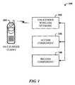
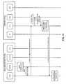
- FIG. 1illustrates a system that facilitates control of network access.
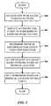
- FIG. 2illustrates a methodology of controlling network access in accordance with the subject innovation.
- FIG. 3illustrates a methodology of providing location-based billing in accordance with another aspect.
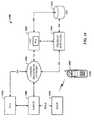
- FIG. 4illustrates a more detailed system that provides network access control of a UMA client in accordance with another aspect of the innovation.
- FIG. 5illustrates a methodology of authenticating by validating a physical endpoint of the subscriber broadband connection and associating the subscriber to an IP address.
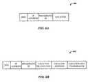
- FIGS. 6A and 6Billustrate examples of record formats that can be employed.
- FIG. 7illustrates a client registration procedure
- FIG. 8illustrates a methodology of identifying and validating a physical location of a broadband customer endpoint that is authorized to allow UMA service.
- FIG. 9illustrates a methodology of correlating a broadband physical location with the originating IP address of the UMA client and subsequently allow or deny UMA service.
- FIG. 10illustrates a methodology of dynamically assigning a cell global identity to specific IEEE 802.11 access points during the UMA client registration procedure for the purpose of providing location-based billing.
- FIG. 11illustrates a methodology of dynamically assigning physical location information to UMA client sessions for the purpose of E911 compliance.
- FIG. 12illustrates an alternative methodology of dynamically assigning physical location information to UMA client sessions for the purpose of E911 compliance.
- FIG. 13illustrates yet another alternative methodology of dynamically assigning physical location information to UMA client sessions for the purpose of E911 compliance.
- FIG. 14illustrates another exemplary architecture according to one innovative aspect.
- FIG. 15illustrates a message flow for an IP registration procedure.
- FIG. 16illustrates message flow for a UMA registration and authorization procedure.
- FIG. 17illustrates a schematic block diagram of a dual-mode handset (DMH) in accordance with an innovative aspect.
- FIG. 18illustrates a block diagram of a computer operable to provide storage and access such as for the UNC and/or HSS.
- FIG. 19illustrates an exemplary GSM network that facilitates DMS access control, location-based billing, and E911 mechanisms according to an innovative aspect.
- a componentcan be, but is not limited to being, a process running on a processor, a processor, a hard disk drive, multiple storage drives (of optical and/or magnetic storage medium), an object, an executable, a thread of execution, a program, and/or a computer.
- a componentcan be, but is not limited to being, a process running on a processor, a processor, a hard disk drive, multiple storage drives (of optical and/or magnetic storage medium), an object, an executable, a thread of execution, a program, and/or a computer.
- an application running on a server and the servercan be a component.
- One or more componentscan reside within a process and/or thread of execution, and a component can be localized on one computer and/or distributed between two or more computers.
- the FCC (Federal Communications Commission) 05-116 VoIP E911 rulesrequire all interconnected VoIP (voice over IP) providers to support E911 calls within 120 days. Although the customer provides the location information, the VoIP provider provides the customer a means of updating this information, whether he or she is at home or away from home. A mechanism to dynamically validate the broadband endpoint is desired if the subscriber is allowed to use more than one broadband endpoint, such as hotspots, for example.
- Described hereinis a service-provider perspective on managing where subscribers may use WiFi to access DMS (dual-mode services).
- DMSdual-mode services
- the DMS technologyis assumed to be UMA (unlicensed mobile access) but could be IMS (IP multimedia subsystem) VoIP.
- This service-provider perspectiveoffers a concept to build upon existing UMA and broadband security procedures to enable a UNC-SGW (UMA network controller-security gateway) to validate the originating IP address of a UMA client.
- UMA-SGWUMA network controller-security gateway
- the physical location of the broadband endpointis used to control DMS access, provide dynamic location based billing, and dynamically comply with E911 regulations.
- the innovationtargets the DSL (digital subscriber line) broadband network, although the same concept may be applied to non-DSL networks such as cable modem networks. It is desired to employ a mechanism that has zero impact on the broadband endpoints and terminal devices.
- the DMSdoes not restrict the physical endpoint.
- the broadband service and RBGW(residential broadband gateway) are transparent to the DMS.
- DMS technologywill be described in the context of UMA, but can also be IMS VoIP technology.
- FIG. 1illustrates a system 100 that facilitates control of network access.
- the subject innovationfacilitates validation and authentication of the physical location of a multi-mode (e.g., DMS) UMA system, thereby restricting the handset from gaining access from unauthorized locations.
- a multi-mode (e.g., DMS) UMA systeme.g., DMS
- dual-mode UMA servicesfor example, at a particular location (e.g., in a subscriber's home, or in a hot spot that is controlled by a carrier) can now be managed to allow or deny service at that location.
- the system 100includes an unlicensed wireless network (UWN) 102 that facilitates communications for a multi-mode UMA client 104 to a radio network.
- An access component 106 of the radio networkis provided that controls access to the radio network by the UMA client 104 based on a physical location of the UMA client 104 .
- the UMA client 104is a dual-mode mobile handset.
- the UWN 102can be a broadband IP network such as a digital subscriber line (DSL) technology, a cable television network, T1/E1, broadband wireless, FTTH (Fiber to the Home), . . . .
- the radio networkcan be a GSM (global system for mobile telecommunications) network and/or a GPRS (general packet radio services) network.
- the UWN 102typically includes a modem (e.g., DSL and/or cable modem) that includes a unique identifier (e.g., a MAC address). Moreover, the modem is assigned a unique IP address by the provider, which IP address is then assigned to the subscriber account information such that the location of the modem can be determined.
- a modeme.g., DSL and/or cable modem
- the modemis assigned a unique IP address by the provider, which IP address is then assigned to the subscriber account information such that the location of the modem can be determined.
- the validation requestis encapsulated in IP and routed through the broadband connection gaining access to the GSM network to provide the same data and voice services that are provided on the GSM, while in the unlicensed WiFi network, using the broadband connection (e.g., DSL) as the GSM transport.
- a server on the radio networkprovides the mapping from the modem MAC address to the handset to the subscriber home location (where the physical location is the subscriber
- the system 100can further comprise a billing component 108 that facilitates billing based on the physical location of the client 104 .
- a billing component 108that facilitates billing based on the physical location of the client 104 .
- the call via a handset that employs the clientcan be structured by the provider to be free.
- the subscriberis making a call via the UMA client handset at a remote location (e.g., a retail establishment)
- a remote locatione.g., a retail establishment
- the physical location of the UMA client handsetcan be determined, this furthers the mandates of E911 compliance.
- FIG. 2illustrates a methodology of controlling network access in accordance with the subject innovation. While, for purposes of simplicity of explanation, the one or more methodologies shown herein, e.g., in the form of a flow chart or flow diagram, are shown and described as a series of acts, it is to be understood and appreciated that the subject innovation is not limited by the order of acts, as some acts may, in accordance therewith, occur in a different order and/or concurrently with other acts from that shown and described herein. For example, those skilled in the art will understand and appreciate that a methodology could alternatively be represented as a series of interrelated states or events, such as in a state diagram. Moreover, not all illustrated acts may be required to implement a methodology in accordance with the innovation.
- a UWN that supports IP packetsis received that provides access to a radio network.
- a cliente.g., UMA
- the physical location of the clientis determined using a UWN identifier.
- access to the radio networkis either allowed or denied based on the physical location of the client.
- a UWN that supports IP packetsis received that provides access to a radio network.
- a UMA client of a subscriberinitiates access to the radio network via the UWN.
- the physical location of the UMA clientis determined using a UWN identifier.
- access to the radio networkis either allowed or denied based on the physical location of the UMA client.
- FIG. 4illustrates a more detailed system 400 that provides network access control of a UMA client 402 in accordance with another aspect of the innovation.
- the UMA client in the handset 402a UNC 404 that provides the interface to the core network via 3GPP specified A/Gb interfaces, an MSC (mobile switching center) 406 , a RADIUS server 408 , a presence manager (PM) 410 and a HSS (home subscriber server) 412 .
- MSCmobile switching center
- RADIUS server 408a RADIUS server 408
- PMpresence manager
- HSShome subscriber server
- the UMA handset 402communicates over an unlicensed wireless network (e.g., WiFi, Bluetooth, . . . ) to an IP access network 414 (e.g., broadband DSL) to the UNC 404 to be authenticated and authorized for access to core network GSM voice and/or GPRS data services. If approved, the subscriber's current location information stored in the core network is updated, and all mobile voice and data traffic is routed to the UMA handset 402 over the UMA network (UMAN), instead of the radio access network.
- an unlicensed wireless networke.g., WiFi, Bluetooth, . . .
- IP access network 414e.g., broadband DSL
- UMANUMA network
- the subject innovationadds novel functionality to the RADIUS server 408 in the form of a RADIUS presence agent 420 and/or to the UNC 404 in the form of a UNC presence agent 422 via a new database.
- the presence agents( 420 and 422 ) facilitate communication of presence notification messages.
- the new databasecan be located anywhere, for example, in the HSS 412 .
- the HSS 412then functions at least like a new RADIUS server.
- the DMS presence notification messagecan include a DSL account E.164 number, an IP address, a UMA E.164 number, IMSI (international mobile subscriber identity), and/or subscriber physical location information (e.g., street address, and the like).
- the IMSIis an ITU-T specification that uniquely identifies a subscriber to a mobile telephone service.
- the IMSIis used in a GSM network, and can be used in all cellular networks to identify at least the phone's home country and carrier.
- the UMA clientsends the following information to the UNC: the IMSI, the AP ID, and the originating IP address.
- the systemcan now go to the HSS 414 and do a search on the IP E.164 address and check to see if it is a valid IP address for this UMA client 402 . If yes, then the system will validate the number and grant service. If the DMS is queried and a valid record is not returned, then the address originated from the IP address was one which was not authorized.
- the DSL carrierscan assign specific discreet location information that corresponds to an IP address.
- a service-provider perspectivefor controlling where a subscriber can use WiFi to access DMS.
- the service-provider perspectivebuilds upon existing UMA and broadband security procedures to enable the UNC-SGW to validate the originating IP address of the UMA client. Solutions include the use of the physical location of the broadband endpoint to control DMS access, provide dynamic location based billing, and dynamically comply with E911 regulations.
- the subject descriptionfocuses on the DSL broadband network, the same concept can be applied to non-DSL networks such as cable modem networks, T1/E1, FTTH, etc.
- Carrierscan now charge differently for converged services depending on where the subscriber is located. For example, if the subscriber uses the parent's DSL service in the home, the call is free. If the subscriber uses a WiFi hotspot at local retail store, the call can be charged at the normal GSM rates, or differently than in the subscriber home.
- FIG. 5illustrates a methodology of authenticating by validating a physical endpoint of the subscriber broadband connection and associating the subscriber to an IP address.
- the broadband modemwill login and obtain an IP address from the Network Access Server's dynamic address pool. For example, as part of the access procedure the RADIUS server will associate the assigned IP address with the broadband account identity (e.g., the POTS (plain old telephone system) E.164 number).
- the broadband service providersends a presence notification message to a new DMS subscriber authorization database (DAD), as indicated at 504 .
- DADDMS subscriber authorization database
- the presence notification messagecan include information used by the UNC-SGW to authorize the UMA client to use the broadband connection based on the broadband account identity and IMSI parameter.
- the UMA clientprovides the IMSI, originating public IP address, and the MAC address of the access point.
- the UNC-SGWvalidates the UMA client's IMSI and public originating IP address pair with the DAD.
- the DADis a virtual element that can reside in the UMAN, and can be part of a larger subscriber database such as the HLR (Home Location Register), HSS (Home Subscriber Server), AAA server, or carrier-specific database.
- Key functions of the DADinclude receiving presence notification messages from broadband service providers, correlating the broadband account identity and public IP address with the UMA subscriber's IMSI and with the current IMSI and IP address, and accepting or rejecting authorization requests from the UNC-SGW based on the UMA client IMSI and originating public IP address.
- the DADcan be provisioned with an appropriate information record for each authorized broadband identity.
- FIG. 6A and 6Billustrate examples of record formats 600 and 602 that can be employed.
- a first record format 600can include the following information.
- IMSIInternational Mobile Subscriber Identity IP Address Public originating IP address of the subscriber's broadband CPE (customer premise equipment) Broadband
- the account number to identify the subscription owner, Identitycan be the same as the POTS E.164 number.
- a second record format 602can include the following information.
- the database recordcan include the IMSI and the E.164 number.
- IMSIInternational Mobile Subscriber Identity IP Address Public originating IP address of the subscriber's broadband CPE Broadband
- the account number to identify the subscription owner, Identitycan be the same as the POTS E.164 number.
- the broadband service provider's security and access control procedurescan be provisioned with one or more IMSIs authorized to use the broadband connection.
- the UNC registration procedurecan include the following MS (mobile station) and AP (access point) addressing parameters (as provided by the UMA specification UMA Stage 2):
- the IMSI associated with the SIM in the terminalThis identifier is provided by the MS to the UNC when it registers to a UNC.
- the UNCmaintains a record for each registered MS.
- the IMSIis used by the UNC to find the appropriate MS record when the UNC receives a BSSMAP (base station system management application part) PAGING message.
- BSSMAP protocolis also used to convey general BSS (base station system) control information between an MSC (mobile switching center) and the BSS.
- An exampleis the allocation of traffic channels between the MSC and the BSS.
- the public IP address of the MSis the source IP present in the outermost IP header of packets received from the MS by the UNC-SGW. If available, this identifier may be used by the UNC to support locations services and fraud detection. It may also be used by service providers to signal managed IP networks IP flows that require QoS (quality of service) treatment.
- the Access Point (AP) IDis the MAC address of the unlicensed mode access point through which the MS is accessing UMA service. This identifier is provided by the MS (obtained via broadcast from the AP) to the UNC via the Up interface, when it requests UMA service.
- the AP-IDmay be used by the UNC to support location services.
- the AP-IDmay also be used by the service provider to restrict UMA service access via only authorized APs.
- FIG. 7illustrates a client registration procedure.
- a client registration procedureis initiated.
- the UNC-SGWvalidates the client IMSI and originating public IP address against the DAD.
- FIG. 8illustrates a methodology of identifying and validating a physical location of a broadband customer endpoint that is authorized to allow UMA service.
- an IP routeris received that interfaces the UWN to the broadband service provider through the broadband modem.
- the subscriber username and passwordis entered, which information is sent to the broadband service provider (e.g., DSL provider), for authentication via a RADIUS server, as indicated at 802 .
- the providerthen authenticates that username and password as being a valid subscriber, and enables service.
- the providerallocates a dynamic IP address (or static IP address) that will be assigned and accepted by the broadband modem. This is handled by the RADIUS server in the broadband network.
- the RADIUS servercollects the username/password, validates the subscriber, and starts the accounting process, and knows the IP address of the subscriber and that the particular subscriber has network access.
- a presence notification messageis sent that includes the broadband E.164 number, a GSM E.164 number, and the physical location data (street address, etc.).
- this datagets sent over to a standard presence interface on the GSM network, which GSM network accepts it, and stores it into a database.
- FIG. 9there is illustrated a methodology of correlating a broadband physical location with the originating IP address of the UMA client and subsequently allow or deny UMA service.
- the UMA cliententers into the home, detects the WiFi network and, receives an IP address and WiFi security data.
- a UMA client registration procedureis automatically started back to the UNC on the GSM network. The registration process includes sending the IP address of the broadband modem and the IMSI to the UNC to setup the secure tunnel and start the standard GSM authentication procedures.
- the UNConce the UNC collects the IMSI and IP address, the UNC initiates a query to the database (e.g., the HSS DIAMETER database) to get the E.164 DSL number, and the IMSI, as indicated at 904 .
- the databasee.g., the HSS DIAMETER database
- the UNCcollects that information and goes back to the legacy GSM network and queries the network to validate the dual mode services.
- a determinationis made whether the broadband physical location is one of the valid serving areas for that particular UMA client.
- serviceis then allowed or denied.
- FIG. 10illustrates a methodology of dynamically assigning a cell global identity to specific IEEE 802.11 access points during the UMA client registration procedure for the purpose of providing location-based billing.
- the UNChas the capability to generate signaling to the MSC, which will generate a CDR (call detail record), which will have a cell global identity (CGI), and that consists of the location area identity plus cell ID.
- CDRcall detail record
- CGIcell global identity
- the UNCdetermines if the physical location is a valid serving area for the UMA client.
- the UNCvalidates and determines that that particular physical location is valid for that UMA client, it grants dual-mode services.
- the UNCdynamically creates a new record in the UMA billing mechanism.
- a CGI numberis generated and assigned for that physical location.
- a dynamically created CGIis applied for those particular call records. Almost all new functionality is provided in UNC via the presence agent. There can also be functionality added to the RADIUS server for the broadband component via a RADIUS presence agent.
- the subscribercan then be billed according to the CDRs that were generated in association with the physical location.
- the physical location informationis collected and stored in a database.
- This databasecan reside in the UNC, and/or in the HSS where there is a notification sent that triggers an E911 database update procedure or in both the UNC and the HSS, for example.
- the physical location informationis then assigned to that particular GSM E.164 number.
- the GSM E.164 numbercan be used to update a PSAP (public safety answering point) database with physical location data for that E.164 number.
- PSAPpublic safety answering point
- the PSAPis the first contact an E911 caller will get.
- the PSAP operatorverifies or obtains the caller's whereabouts (location information), determines the nature of the emergency and decides which emergency response teams to notify.
- FIG. 12illustrates an alternative methodology of dynamically assigning physical location information to UMA client sessions for the purpose of E911 compliance.
- the physical location informationis collected and stored in a database.
- This databasecan reside in the UNC, and/or in the HSS where there is a notification sent that triggers an E911 database update procedure or in both the UNC and the HSS, for example.
- the physical locationcan be assigned as a pANI (pseudo automatic number identification) for the base transceiver station (BTS) towers.
- the pANIis a modification of the ANI, and is used to pass information across systems that can handle ANI traffic.
- the pANIis a number employed in wireless E911 call setup that can be used to route the call the appropriate PSAP.
- the pANIgenerally identifies the cell/sector from which the call was made, whereas the ANI carries the actual telephone number of the wireline caller.
- an E911 call centercan obtain the telephone number and a general location of the caller based on the pANI number.
- a pseudo telephone numberis created and assigned to a BTS tower, a cell sector, and stored in a PSAP database.
- FIG. 13illustrates yet another alternative methodology of dynamically assigning physical location information to UMA client sessions for the purpose of E911 compliance.
- the callerinitiates an E911 call through the broadband network.
- the UNCcorrelates the GSM E.164 number with the broadband E.164 number (e.g., DSL E.164 number).
- the UNCtransposes the E.164 numbers when sending the digits to the selected tandem. That way, the UNC makes it appear as though the call is originating from a land line.
- the broadband E.164 numberwill already have that physical street address for that telephone number.
- FIG. 14illustrates another exemplary architecture 1400 according to one innovative aspect.
- a dual mode handset (DMH) 1402is provided, which can be a UMA handset.
- DMHdual mode handset
- IMS VoIP handsetscan also be supported.
- the innovationhas zero impact on the DMH and reuses the IMSI and originating IP address during the UMA registration procedure.
- the wireless handset 1402communicates with an RBGW 1404 .
- This element 1404can include any or all of a broadband modem (in this case a DSL modem), an IP router, a WiFi access point, and analog terminal adapters.
- the RBGW 1404uses the PPPoE protocol for IP access to a broadband network 1406 .
- the RBGWinterfaces to a RADIUS (remote authentication dial-in user service) 1408 , which authenticates the RBGW, authorizes service, and assigns an IP address, for example.
- RADIUSremote authentication dial-in user service
- a presence user agent (PUA) 1410interfaces to the RADIUS server 1408 and the broadband network 1406 .
- the PUA 1410provides functionality to notify the 3GPP network of the physical attributes (e.g., identity, IP address, and location) of the broadband endpoint.
- a UNC 1412interfaces to the broadband network 1406 and includes the SGW that authenticates and authorizes service to the DMH client 1402 (e.g., UMA).
- a new function (a presence user agent) in the UNCis introduced that queries an HSS 1414 to validate broadband endpoints during the UMA registration procedure.
- a presence server 1416is provided that receives presence information from the PUA 1410 and updates the subscriber record in the HSS 1414 .
- the HSS 1414is part of the IMS core used for subscriber provisioning and stores profiles.
- a new schemais introduced to support the correlation of broadband identities and IP addresses with IMSI data. This concept assumes the HSS includes the DAD.
- the RADIUS elementis assumed to include the network access server and aggregator functions.
- FIG. 15illustrates a message flow for an IP registration procedure.
- a PPPoE sessionis started and established between the RBGW and RADIUS node. This process authenticates the RBGW, initiates a PPP session, assigns an IP address, and starts accounting. A result is that an IP address is assigned to the RBGW (e.g., a DSL modem).
- the RADIUS nodethen notifies the PUA of the broadband service identity, typically the POTS E.164 number, and the IP address assigned to the RBGW. This notification triggers the PUA to query the broadband subscriber database (not shown) to determine if the broadband identity is allowed to support DMS. If DMS is allowed, the PUA collects the endpoint location information from the broadband subscriber database.
- DMS authorizationis validated for the broadband endpoint.
- a DMS authorization and presence messageis created.
- the PUAthen sends the DMS authorization and presence message to the presence server.
- This notificationtriggers the presence server to initiate a subscriber profile update in the DAD, here located in the HSS.
- the presence serverupdates the subscriber's record in the DAD, in this case the HSS, with the originating IP address of the authorized broadband endpoint.
- the UNCuses this information during the UMA registration procedure. At this point, IP address registration is complete.
- FIG. 16illustrates message flow for a UMA registration and authorization procedure.
- a PPPoEis session is active to the RBGW.
- the DMHinitiates and completes a WiFi association process that includes the IEEE 802.11 security.
- the DMHinitiates the UMA registration procedure with the UNC.
- the UNCidentifies the IMSI and originating IP address in the registration message and IP packets.
- the UNCqueries the HSS for the IMSI and originating IP address. If found, the UNC allows DMS access for this broadband endpoint. If not, access is denied. A result is that the originating IP address and IMSI are authorized.
- the UMA client and UNCcomplete the UMA registration process including SIM Authentication (not shown) and an IPsec tunnel. The UMA client registration is then complete.
- a combination of originating IP address and access point MAC addresscan be used to identify UMA caller's E911 location.
- the subject innovationcan envision that a static IP address is required to support E911 for enterprise environments that use a single, public originating IP address to serve multiple WiFi access points in multiple locations.
- dynamic IP addressingcan also be used to support the enterprise.
- a broadband provider conceptenvisions a self-provisioning mechanism whereby the subscriber and/or DMS provider can be allowed to update a broadband account profile to set DMS permissions for the broadband endpoint.
- each broadband accountcan be provisioned to allow or deny the self-provisioning of DMS-allowed IMSI(s).
- the broadband subscribercontrols which DMS E.164 (or IMSIs) are allowed to use his or her broadband service.
- Each broadband accountcan be self-provisioned by the subscriber or other mechanism with one or more IMSIs that are allowed DMS from this endpoint.
- One methodmay be for the DMS provider to update the broadband account with a list of authorized IMSIs.
- the broadband providercan enable a PPPoE access concentrator to trigger the appropriate presence notification to the DAD via the PUA.
- the innovationcan assume that no additional per subscriber provisioning is required.
- the DADcan use the IMSI as the key field.
- the DADcan be dynamically provisioned as part of the standard DMS provisioning process.
- a presence servercan be employed to receive notifications from the broadband provider PUA and update the DAD.
- the DMS authentication and access control element(in this case the UNC-SGW) can query the DAD during the DMS registration procedure to allow or deny DMS based on the DMH IMSI and originating IP address.
- E911 call handling and database proceduresrequire the DMS provider to identify the appropriate PSAP via the E911 tandem or selective router.
- the DMS providerassociates the location of the broadband endpoint with the appropriate PSAP.
- the DMS providermay update an automatic location information (ALI) database with the current information of the DMS E.164 number.
- ALIautomatic location information
- the DMS Providercan enable the DMS E911 call to masquerade as a fixed wireline call by replacing the DMS E.164 number's calling number (ANI) ID with the broadband E.164 number. This procedure puts DMS E911 calls on par with fixed wireline E911 calls.
- the DMS handsetcan provide a visual indicator to inform the subscriber of his or her E911 location status (e.g., good, unavailable, other).
- the DMS providercan provide an E911 location update to the DMS handset and expose this information to the subscriber.
- the enterpriseis responsible for updating (e.g., mechanized and/or via the broadband provider) the DAD with the current and accurate location information for access points in the enterprise.
- a manual processcan be used to update the DAD.
- a manual processcan be implemented to associate an access point MAC address with the physical endpoint location. See the following DAD record example for multiple access points.
- a second querycan be made to search for an access point record. If the access point is found and its BROADBAND_ID field matches the broadband record BROADBAND_ID field, the E911 location information is set to the AP_LOCATION value. This technique for supporting multiple access points can require new development to the PSAP and/or ALI.
- FIG. 17illustrates a schematic block diagram of a dual-mode handset (DMH) 1700 in accordance with an innovative aspect.
- DMHdual-mode handset
- FIG. 17 and the following discussionare intended to provide a brief, general description of a suitable environment 1700 in which the various aspects of the innovation can be implemented. While the description includes a general context of computer-executable instructions, those skilled in the art will recognize that the innovation also can be implemented in combination with other program modules and/or as a combination of hardware and software.
- applicationscan include routines, programs, components, data structures, etc., that perform particular tasks or implement particular abstract data types.
- inventive methodscan be practiced with other system configurations, including single-processor or multiprocessor systems, minicomputers, mainframe computers, as well as personal computers, hand-held computing devices, microprocessor-based or programmable consumer electronics, and the like, each of which can be operatively coupled to one or more associated devices.
- a computing devicecan typically include a variety of computer-readable media.
- Computer-readable mediacan be any available media that can be accessed by the computer and includes both volatile and non-volatile media, removable and non-removable media.
- Computer-readable mediacan comprise computer storage media and communication media.
- Computer storage mediaincludes both volatile and non-volatile, removable and non-removable media implemented in any method or technology for storage of information such as computer-readable instructions, data structures, program modules or other data.
- Computer storage mediacan include, but is not limited to, RAM, ROM, EEPROM, flash memory or other memory technology, CD-ROM, digital video disk (DVD) or other optical disk storage, magnetic cassettes, magnetic tape, magnetic disk storage or other magnetic storage devices, or any other medium which can be used to store the desired information and which can be accessed by the computer.
- Communication mediatypically embodies computer-readable instructions, data structures, program modules or other data in a modulated data signal such as a carrier wave or other transport mechanism, and includes any information delivery media.
- modulated data signalmeans a signal that has one or more of its characteristics set or changed in such a manner as to encode information in the signal.
- communication mediaincludes wired media such as a wired network or direct-wired connection, and wireless media such as acoustic, RF, infrared and other wireless media. Combinations of the any of the above should also be included within the scope of computer-readable media.
- the DMH 1700(similar to client handset 104 , 402 , 1402 ) includes a processor 1702 for controlling and processing all onboard operations and functions.
- a memory 1704interfaces to the processor 1702 for storage of data and one or more applications 1706 (e.g., a video player software, user feedback component software, etc.).
- applications 1706e.g., a video player software, user feedback component software, etc.
- Other applicationscan include voice recognition of predetermined voice commands that facilitate initiation of the user feedback signal, as well as those described infra.
- the applications 1706can be stored in the memory 1704 and/or in a firmware 1708 , and executed by the processor 1702 from either or both the memory 1704 or/and the firmware 1708 .
- the firmware 1708can also store startup code for execution in initializing the DMH 1700 .
- a communication component 1710interfaces to the processor 1702 to facilitate wired/wireless communication with external systems, e.g., cellular networks, VoIP networks, and so on.
- the communications component 1710also includes a GSM transceiver 1711 and a WiFi transceiver 1713 for corresponding signal communications.
- the DMH 1700can be a device such as a cellular telephone, a PDA with mobile communications capabilities, and messaging-centric devices.
- the DMH 1700includes a display 1712 for displaying text, images, video, telephony functions (e.g., a Caller ID function), setup functions, and for user input.
- the display 1712can also accommodate the presentation of multimedia content.
- a serial I/O interface 1714is provided in communication with the processor 1702 to facilitate wired and/or wireless serial communications (e.g., USB, and/or IEEE 1394) via a hardwire connection, and other serial input devices (e.g., a keyboard, keypad, and mouse). This supports updating and troubleshooting the DMH 1700 , for example.
- Audio capabilitiesare provided with an audio I/O component 1716 , which can include a speaker for the output of audio signals related to, for example, indication that the user pressed the proper key or key combination to initiate the user feedback signal.
- the audio I/O component 1716also facilitates the input of audio signals via a microphone to record data and/or telephony voice data, and for inputting voice signals for telephone conversations.
- the DMH 1700can include a slot interface 1718 for accommodating a SIC (Subscriber Identity Component) in the form factor of a card Subscriber Identity Module (SIM) or universal SIM 1720 , and interfacing the SIM card 1720 with the processor 1702 .
- SIMSubscriber Identity Module
- the SIM card 1720can be manufactured into the DMH 1700 , and updated by downloading data and software thereinto.
- the DMH 1700can process IP data traffic via the communication component 1710 to accommodate IP traffic from an IP network such as, for example, the Internet, a corporate intranet, a home network, a person area network, etc., via an ISP or broadband cable provider.
- IP networksuch as, for example, the Internet, a corporate intranet, a home network, a person area network, etc.
- VoIP trafficcan be utilized by the DMH 1700 and IP-based multimedia content can be received in either an encoded or decoded format.
- a video processing component 1722(e.g., a camera) can be provided for decoding encoded multimedia content.
- the DMH 1700also includes a power source 1724 in the form of batteries and/or an AC power subsystem, which power source 1724 can interface to an external power system or charging equipment (not shown) via a power I/O component 1726 .
- the DMH 1700can also include a video component 1730 for processing video content received and, for recording and transmitting video content.
- a location tracking component 1732facilitates geographically locating the DMH 1700 . As described hereinabove, this can occur when the user initiates the feedback signal automatically or manually.
- a user input component 1734facilitates the user initiating the quality feedback signal.
- the input componentcan include such conventional input device technologies such as a keypad, keyboard, mouse, stylus pen, and touch screen, for example.
- a hysteresis component 1736facilitates the analysis and processing of hysteresis data, which is utilized to determine when to associate with the access point.
- a software trigger component 1738can be provided that facilitates triggering of the hysteresis component 1738 when the WiFi transceiver 1713 detects the beacon of the access point.
- a SIP client 1740enables the DMH 1700 to support SIP protocols and register the subscriber with the SIP registrar server.
- the DMH 1700includes an indoor network radio transceiver 1713 (e.g., WiFi transceiver). This function supports the indoor radio link, such as IEEE 802.11, for the dual-mode GSM handset 1700 .
- the DMH 1700can also include an internal analog terminal adapter (ATA) 1742 for interfacing to analog devices such as modems and fax machines, for example.
- ATAanalog terminal adapter
- an external ATA module 1744can be provided for the same purposes as the internal ATA module 1742 .
- FIG. 18there is illustrated a block diagram of a computer operable to provide storage and access such as for the UNC and/or HSS.
- FIG. 18 and the following discussionare intended to provide a brief, general description of a suitable computing environment 1800 in which the various aspects of the innovation can be implemented. While the description above is in the general context of computer-executable instructions that may run on one or more computers, those skilled in the art will recognize that the innovation also can be implemented in combination with other program modules and/or as a combination of hardware and software.
- program modulesinclude routines, programs, components, data structures, etc., that perform particular tasks or implement particular abstract data types.
- inventive methodscan be practiced with other computer system configurations, including single-processor or multiprocessor computer systems, minicomputers, mainframe computers, as well as personal computers, hand-held computing devices, microprocessor-based or programmable consumer electronics, and the like, each of which can be operatively coupled to one or more associated devices.
- the illustrated aspects of the innovationmay also be practiced in distributed computing environments where certain tasks are performed by remote processing devices that are linked through a communications network.
- program modulescan be located in both local and remote memory storage devices.
- Computer-readable mediacan be any available media that can be accessed by the computer and includes both volatile and non-volatile media, removable and non-removable media.
- Computer-readable mediacan comprise computer storage media and communication media.
- Computer storage mediaincludes both volatile and non-volatile, removable and non-removable media implemented in any method or technology for storage of information such as computer-readable instructions, data structures, program modules or other data.
- Computer storage mediaincludes, but is not limited to, RAM, ROM, EEPROM, flash memory or other memory technology, CD-ROM, digital video disk (DVD) or other optical disk storage, magnetic cassettes, magnetic tape, magnetic disk storage or other magnetic storage devices, or any other medium which can be used to store the desired information and which can be accessed by the computer.
- Communication mediatypically embodies computer-readable instructions, data structures, program modules or other data in a modulated data signal such as a carrier wave or other transport mechanism, and includes any information delivery media.
- modulated data signalmeans a signal that has one or more of its characteristics set or changed in such a manner as to encode information in the signal.
- communication mediaincludes wired media such as a wired network or direct-wired connection, and wireless media such as acoustic, RF, infrared and other wireless media. Combinations of the any of the above should also be included within the scope of computer-readable media.
- the exemplary environment 1800 for implementing various aspectsincludes a computer 1802 , the computer 1802 including a processing unit 1804 , a system memory 1806 and a system bus 1808 .
- the system bus 1808couples system components including, but not limited to, the system memory 1806 to the processing unit 1804 .
- the processing unit 1804can be any of various commercially available processors. Dual microprocessors and other multi-processor architectures may also be employed as the processing unit 1804 .
- the system bus 1808can be any of several types of bus structure that may further interconnect to a memory bus (with or without a memory controller), a peripheral bus, and a local bus using any of a variety of commercially available bus architectures.
- the system memory 1806includes read-only memory (ROM) 1810 and random access memory (RAM) 1812 .
- ROMread-only memory
- RAMrandom access memory
- a basic input/output system (BIOS)is stored in a non-volatile memory 1810 such as ROM, EPROM, EEPROM, which BIOS contains the basic routines that help to transfer information between elements within the computer 1802 , such as during start-up.
- the RAM 1812can also include a high-speed RAM such as static RAM for caching data.
- the computer 1802further includes an internal hard disk drive (HDD) 1814 (e.g., EIDE, SATA), which internal hard disk drive 1814 may also be configured for external use in a suitable chassis (not shown), a magnetic floppy disk drive (FDD) 1816 , (e.g., to read from or write to a removable diskette 1818 ) and an optical disk drive 1820 , (e.g., reading a CD-ROM disk 1822 or, to read from or write to other high capacity optical media such as the DVD).
- the hard disk drive 1814 , magnetic disk drive 1816 and optical disk drive 1820can be connected to the system bus 1808 by a hard disk drive interface 1824 , a magnetic disk drive interface 1826 and an optical drive interface 1828 , respectively.
- the interface 1824 for external drive implementationsincludes at least one or both of Universal Serial Bus (USB) and IEEE 1394 interface technologies. Other external drive connection technologies are within contemplation of the subject innovation.
- the drives and their associated computer-readable mediaprovide nonvolatile storage of data, data structures, computer-executable instructions, and so forth.
- the drives and mediaaccommodate the storage of any data in a suitable digital format.
- computer-readable mediarefers to a HDD, a removable magnetic diskette, and a removable optical media such as a CD or DVD, it should be appreciated by those skilled in the art that other types of media which are readable by a computer, such as zip drives, magnetic cassettes, flash memory cards, cartridges, and the like, may also be used in the exemplary operating environment, and further, that any such media may contain computer-executable instructions for performing the methods of the disclosed innovation.
- a number of program modulescan be stored in the drives and RAM 1812 , including an operating system 1830 , one or more application programs 1832 , other program modules 1834 and program data 1836 . All or portions of the operating system, applications, modules, and/or data can also be cached in the RAM 1812 . It is to be appreciated that the innovation can be implemented with various commercially available operating systems or combinations of operating systems.
- a usercan enter commands and information into the computer 1802 through one or more wired/wireless input devices, e.g., a keyboard 1838 and a pointing device, such as a mouse 1840 .
- Other input devicesmay include a microphone, an IR remote control, a joystick, a game pad, a stylus pen, touch screen, or the like.
- These and other input devicesare often connected to the processing unit 1804 through an input device interface 1842 that is coupled to the system bus 1808 , but can be connected by other interfaces, such as a parallel port, an IEEE 1394 serial port, a game port, a USB port, an IR interface, etc.
- a monitor 1844 or other type of display deviceis also connected to the system bus 1808 via an interface, such as a video adapter 1846 .
- a computertypically includes other peripheral output devices (not shown), such as speakers, printers, etc.
- the computer 1802may operate in a networked environment using logical connections via wired and/or wireless communications to one or more remote computers, such as a remote computer(s) 1848 .
- the remote computer(s) 1848can be a workstation, a server computer, a router, a personal computer, portable computer, microprocessor-based entertainment appliance, a peer device or other common network node, and typically includes many or all of the elements described relative to the computer 1802 , although, for purposes of brevity, only a memory/storage device 1850 is illustrated.
- the logical connections depictedinclude wired/wireless connectivity to a local area network (LAN) 1852 and/or larger networks, e.g., a wide area network (WAN) 1854 .
- LAN and WAN networking environmentsare commonplace in offices and companies, and facilitate enterprise-wide computer networks, such as intranets, all of which may connect to a global communications network, e.g., the Internet.
- the computer 1802When used in a LAN networking environment, the computer 1802 is connected to the local network 1852 through a wired and/or wireless communication network interface or adapter 1856 .
- the adaptor 1856may facilitate wired or wireless communication to the LAN 1852 , which may also include a wireless access point disposed thereon for communicating with the wireless adaptor 1856 .
- the computer 1802can include a modem 1858 , or is connected to a communications server on the WAN 1854 , or has other means for establishing communications over the WAN 1854 , such as by way of the Internet.
- the modem 1858which can be internal or external and a wired or wireless device, is connected to the system bus 1808 via the serial port interface 1842 .
- program modules depicted relative to the computer 1802can be stored in the remote memory/storage device 1850 . It will be appreciated that the network connections shown are exemplary and other means of establishing a communications link between the computers can be used.
- the computer 1802is operable to communicate with any wireless devices or entities operatively disposed in wireless communication, e.g., a printer, scanner, desktop and/or portable computer, portable data assistant, communications satellite, any piece of equipment or location associated with a wirelessly detectable tag (e.g., a kiosk, news stand, restroom), and telephone.
- any wireless devices or entities operatively disposed in wireless communicatione.g., a printer, scanner, desktop and/or portable computer, portable data assistant, communications satellite, any piece of equipment or location associated with a wirelessly detectable tag (e.g., a kiosk, news stand, restroom), and telephone.
- the communicationcan be a predefined structure as with a conventional network or simply an ad hoc communication between at least two devices.
- WiFiWireless Fidelity
- WiFiis a wireless technology similar to that used in a cell phone that enables such devices, e.g., computers, to send and receive data indoors and out; anywhere within the range of a base station.
- WiFi networksuse radio technologies called IEEE 802.11 (a, b, g, etc.) to provide secure, reliable, fast wireless connectivity.
- IEEE 802.11a, b, g, etc.
- a WiFi networkcan be used to connect computers to each other, to the Internet, and to wired networks (which use IEEE 802.3 or Ethernet).
- WiFi networksoperate in the unlicensed 2.4 and 5 GHz radio bands, at an 11 Mbps (802.11a) or 54 Mbps (802.11b) data rate, for example, or with products that contain both bands (dual band), so the networks can provide real-world performance similar to the basic 10BaseT wired Ethernet networks used in many offices.
- FIG. 19illustrates an exemplary GSM network 1900 that facilitates DMS access control, location-based billing, and E911 mechanisms according to an innovative aspect.
- the GSM systemdesigned as a 2G cellular communications system, utilizes TDMA (time division multiple access) technology to enable greater call capacity.
- Digitally-encoded speechcan also be ciphered to retain call privacy.
- Voice callsare the primary function of the GSM system. To achieve this, the speech is digitally encoded, and later decoded using a vocoder.
- GSMalso supports a variety of other data services, although the performance for such data services (e.g., facsimile videotext and teletext) is slow.
- One data serviceincludes SMS that allows bi-directional messaging, store-and-forward delivery, and alphanumeric messages.
- SMSallows bi-directional messaging, store-and-forward delivery, and alphanumeric messages.
- the overall system definition for GSMdescribes not only the air interface, but also the network. GSM uses 200 KHz RF channels, and are typically multiplexed to, for example, enable eight users to access each carrier.
- the GSM network 1900includes a base station subsystem (BSS) 1902 , a network subsystem (NSS) 1904 and a GPRS core network 1906 .
- the BSS 1902can include one or more base transceiver stations (BTS) 1908 and a base station controller (BSC) 1910 connected together on an A-bis interface.
- BTSbase transceiver stations
- BSCbase station controller
- the BTS and accompanying base stations(not shown) connect a cell phone to a cellular network.
- Base stationsare all interconnected to facilitate roaming from one cell to another via a process called handover, without losing the cell connection.
- a packet control unit (PCU) 1912is shown connected to the BTS 1910 although the exact position of this can depend on the vendor architecture.
- the BSS 1902is connected by the air interface Um to a mobile terminal 1914 .
- the BTS 1908are the actual transmitters and receivers of radio signals.
- TRXstransceivers
- a BTS for anything other than a picocellwill have several different transceivers (TRXs) which allow it to serve several different frequencies or even several different cells (in the case of sectorized base stations).
- each pointing in different directionsit is possible to sectorise the base station so that several different cells are served from the same location. This increases the traffic capacity of the base station (each frequency can carry eight voice channels) while not greatly increasing the interference caused to neighboring cells (in any given direction, only a small number of frequencies are being broadcast).
- the BSC 1910provides the intelligence behind the BTS 1908 .
- a BSCcan have tens or even hundreds of BTSs 1908 under its control.
- the BSC 1910handles allocation of radio channels, receives measurements from the mobile phones, and controls handovers from BTS to BTS (except in the case of an inter-MSC handover in which case control is in part the responsibility of the an MSC).
- One function of the BSC 1910is to act as a concentrator such that many different low capacity connections to the BTS 1908 can become reduced to a smaller number of connections towards the MSC.
- networksare often structured to have many BSCs 1910 distributed into regions near the BTS 1908 which are then connected to large centralized MSC sites.
- the PCU 1912can perform some of the equivalent tasks of the BSC 1910 .
- the allocation of channels between voice and datacan be controlled by the base station, but once a channel is allocated to the PCU 1912 , the PCU 1912 takes full control over that channel.
- the PCU 1912can be built into the base station, built into the BSC, or even in some architectures, it can be at an SGSN site.
- the BSS 1902connects to the NSS 1904 by an A interface.
- the NSS 1904is shown containing an MSC 1916 connected via an SS7 network 1918 to an HLR 1920 .
- the AuC and the EIRalthough technically separate functions from the HLR 1920 , are shown together since combining them can be performed in the network.
- the combination of a cell phone 1914 and a SIM cardcreates a special digital “signature” that includes a subscriber number which is sent from the cell phone 1914 to the nearest BTS 1908 asking that the subscriber of a particular network be allowed to use the network.
- the requestis passed on along the network of BTS 1908 to the heart of a cellular network, the MSC 1916 .
- the MSCalso routes all incoming and outgoing calls to and from the fixed-line networks or other cellular networks.
- another section of the MSC called the VLRchecks whether the caller is actually allowed to make that call. For example, if the caller is barred for international dialing, a message to that effect will be generated by the VLR, sent along the network, and almost instantly back to the cell phone.
- the MSC 1916also contains the component called HLR 1920 that provides the administrative information required to authenticate, register and locate the caller as that network's subscriber. Once the HLR has received a log-on request, the HLR 1920 immediately checks the special “signature” contained in the request against the HLR special subscriber database. If the subscription is current, the MSC 1916 sends a message back to the phone via the network of BTS 1908 that indicates the caller is allowed to access the network. The name or code of that network will appear on the LCD screen of the cell phone 1914 . Once this network “name” message appears on the phone LCD screen, it means the caller is connected to the network and able to make and receive calls.
- HLR 1920provides the administrative information required to authenticate, register and locate the caller as that network's subscriber.
- the HLR 1920registers which base station the cell phone is currently connected to, so that when the network MSC 1916 needs to route an incoming call to the cell phone number, it will first check the HLR 1920 to see where the cell phone is located. Periodically, the cell phone will send a message to the network indicating where it is, in a process called polling.
- pollinga process called polling.
- the combination of the tracking function and the caller's unique digital signatureallows the MSC 1916 to route that call to the precise base station the cell phone happens to be connected to, and then exclusively to the cell phone, even if a number of other subscribers are simultaneously connected to that base station.
- the HLR 1920When traveling to another cell while driving, for example, the HLR 1920 is automatically updated, and continues to monitor where exactly it should route the calls should the caller then move within range of another base station. This routing procedure means that out of hundreds of thousands of subscribers, only the correct cell phone will ring when necessary.
- the NSS 1904has a direct connection to the PSTN 1922 from the MSC 1916 . There is also a connection to from the NSS 1904 to the GPRS core network 1906 via a Gr/Gs interface although this is optional and not always implemented.
- the illustrated GPRS Core Network 1906is simplified to include a SGSN 1924 (connected to the BSS 1902 by the Gb interface) and a GGSN 1926 .
- the SGSN 1924 and the GGSN 1926are connected together by a private IP network 1928 called a GPRS backbone shown as the Gn reference point.
- a computer 1930is depicted as connecting to the core network 1906 via an Internet or corporate network 1932 .
- SMSCnetwork SMS Center
- SMSCa special facility that handles short messages.
- the SMSCgenerates the special SMS message that notifies the caller when they have mail waiting in a Mailbox. SMS messages can be received on an SMS-capable cell phone even while the caller is on a voice call. This is because the SMS messages are sent on a different radio frequency, the GSM data channel, than voice calls, so that the two never interfere.
Landscapes
- Engineering & Computer Science (AREA)
- Computer Security & Cryptography (AREA)
- Computer Networks & Wireless Communication (AREA)
- Signal Processing (AREA)
- Computer Hardware Design (AREA)
- Computing Systems (AREA)
- General Engineering & Computer Science (AREA)
- Mobile Radio Communication Systems (AREA)
Abstract
Description
| Field Name | Description |
| IMSI | International Mobile Subscriber Identity |
| IP Address | Public originating IP address of the subscriber's |
| broadband CPE (customer premise equipment) | |
| Broadband | The account number to identify the subscription owner, |
| Identity | can be the same as the POTS E.164 number. |
| Location | Optional field with physical location information of the |
| broadband endpoint. May be the street address or geo | |
| coordinates used for E911 location information. | |
| Field Name | Description |
| IMSI | International Mobile Subscriber Identity |
| IP Address | Public originating IP address of the subscriber's |
| broadband CPE | |
| Broadband | The account number to identify the subscription owner, |
| Identity | can be the same as the POTS E.164 number. |
| Location | Optional field used by the UNC to determine the |
| Billing | appropriate CGI (cell global identity) value to be used in |
| Code | the CDR (call detail record). |
| Location | Optional field with physical address information of the |
| Address | broadband endpoint. |
| Location Geo | Optional field with lat/long of the endpoint used for |
| Coordinates | E911 compliance. |
| Field Name | Value | ||
| AP_MAC_ADDRESS | 00-05-9A-3C-78-00 | ||
| BROADBAND_ID | 404-555-1212 | ||
| AP_LOCATION | 5565 Glenridge Connector, 9thfloor | ||
Claims (29)
Priority Applications (15)
| Application Number | Priority Date | Filing Date | Title |
|---|---|---|---|
| US11/159,606US7864673B2 (en) | 2005-05-24 | 2005-06-23 | Dynamic dual-mode service access control, location-based billing, and E911 mechanisms |
| US11/379,022US20060268902A1 (en) | 2005-05-24 | 2006-04-17 | Dynamic dual-mode service access control, location-based billing, and e911 mechanisms |
| ES06770572TES2841728T3 (en) | 2005-05-24 | 2006-05-18 | Dynamic dual mode service access control, location-based billing and E911 mechanisms |
| PCT/US2006/019258WO2006127393A1 (en) | 2005-05-24 | 2006-05-18 | Dynamic dual - mode service access control, location - based billing, and e911 mechanisms |
| EP06770572.3AEP1884129B1 (en) | 2005-05-24 | 2006-05-18 | Dynamic dual - mode service access control |
| ES06760167TES2835024T3 (en) | 2005-05-24 | 2006-05-18 | Dynamic dual mode service access control, location-based billing and e911 mechanisms |
| DK06760167.4TDK1884087T3 (en) | 2005-05-24 | 2006-05-18 | Dynamic dual mode service access control, location based billing, and e911 mechanisms |
| PCT/US2006/019408WO2006127445A2 (en) | 2005-05-24 | 2006-05-18 | Dynamic dual-mode service access control, location-based billing, and e911 mechanisms |
| EP06760167.4AEP1884087B8 (en) | 2005-05-24 | 2006-05-18 | Dynamic dual-mode service access control, location-based billing, and e911 mechanisms |
| JP2008513548AJP5061100B2 (en) | 2005-05-24 | 2006-05-18 | Dynamic dual-mode service access control, location-based billing, and E911 mechanism |
| DK06770572.3TDK1884129T3 (en) | 2005-05-24 | 2006-05-18 | Dynamic dual mode service access control, location-based billing and e911 mechanisms |
| JP2008513559AJP4904345B2 (en) | 2005-05-24 | 2006-05-18 | Dynamic dual-mode service access control, location-based billing, and E911 mechanism |
| JP2012132150AJP5389224B2 (en) | 2005-05-24 | 2012-06-11 | System for controlling network access |
| US13/856,682US9226152B2 (en) | 2005-05-24 | 2013-04-04 | Dynamic dual-mode service access control, location-based billing, and E911 mechanisms |
| US14/972,922US10044852B2 (en) | 2005-05-24 | 2015-12-17 | Dynamic dual-mode service access control, location-based billing, and E911 mechanisms |
Applications Claiming Priority (2)
| Application Number | Priority Date | Filing Date | Title |
|---|---|---|---|
| US68399205P | 2005-05-24 | 2005-05-24 | |
| US11/159,606US7864673B2 (en) | 2005-05-24 | 2005-06-23 | Dynamic dual-mode service access control, location-based billing, and E911 mechanisms |
Related Child Applications (1)
| Application Number | Title | Priority Date | Filing Date |
|---|---|---|---|
| US11/379,022Continuation-In-PartUS20060268902A1 (en) | 2005-05-24 | 2006-04-17 | Dynamic dual-mode service access control, location-based billing, and e911 mechanisms |
Publications (2)
| Publication Number | Publication Date |
|---|---|
| US20070008885A1 US20070008885A1 (en) | 2007-01-11 |
| US7864673B2true US7864673B2 (en) | 2011-01-04 |
Family
ID=37452627
Family Applications (1)
| Application Number | Title | Priority Date | Filing Date |
|---|---|---|---|
| US11/159,606Active2027-12-10US7864673B2 (en) | 2005-05-24 | 2005-06-23 | Dynamic dual-mode service access control, location-based billing, and E911 mechanisms |
Country Status (6)
| Country | Link |
|---|---|
| US (1) | US7864673B2 (en) |
| EP (1) | EP1884087B8 (en) |
| JP (1) | JP4904345B2 (en) |
| DK (1) | DK1884087T3 (en) |
| ES (1) | ES2835024T3 (en) |
| WO (1) | WO2006127445A2 (en) |
Cited By (27)
| Publication number | Priority date | Publication date | Assignee | Title |
|---|---|---|---|---|
| US20080049910A1 (en)* | 2004-07-02 | 2008-02-28 | Greg Pounds | Method and Apparatus for Leveraging a Stimulus/Response Model to Send Information Through a Firewall via SIP and for Receiving a Response Thereto vai HTML |
| US20090104946A1 (en)* | 2007-10-23 | 2009-04-23 | Broadcom Corporation | Systems and methods for providing intelligent mobile communication endpoints |
| US20100010888A1 (en)* | 2008-07-14 | 2010-01-14 | Richard Maertz | Methods and systems for offering purchase incentives |
| US20100014506A1 (en)* | 2008-07-17 | 2010-01-21 | Linkola Janne P | System and method for selectively provisioning telecommunications services between an access point and a telecommunications network based on landline telephone detection |
| US20100062768A1 (en)* | 2007-03-08 | 2010-03-11 | Telefonaktiebolaget Lm Ericsson (Publ) | Method and Apparatus for Selecting a Service Area Identifier for a User Equipment in a Wireless System |
| US20100080202A1 (en)* | 2006-09-21 | 2010-04-01 | Mark Hanson | Wireless device registration, such as automatic registration of a wi-fi enabled device |
| US20100159967A1 (en)* | 2004-07-02 | 2010-06-24 | Pounds Gregory E | Method and apparatus for a family center |
| US20100203898A1 (en)* | 2007-07-09 | 2010-08-12 | Rogier Noldus | Unlicensed Mobile Access (UMA) Terminal Location in a Communications Network |
| US20110019999A1 (en)* | 2009-07-24 | 2011-01-27 | Jacob George | Location Tracking Using Fiber Optic Array Cables and Related Systems and Methods |
| US20110149802A1 (en)* | 2008-09-19 | 2011-06-23 | Nec Corporation | Method for personal network service configuration and system for personal network service configuration |
| US20130083785A1 (en)* | 2009-02-27 | 2013-04-04 | Samir Hodroj | System and method for provisioning telecommunications services between an access point and a telecommunications network and providing missing information notification |
| US8626855B2 (en) | 2004-07-02 | 2014-01-07 | Broadsoft Casabi, Llc | Method and apparatus for cordless phone and other telecommunications services |
| US8885635B2 (en) | 2008-07-17 | 2014-11-11 | T-Mobile Usa, Inc. | System and method for selectively provisioning telecommunications services between an access point and a telecommunications network using a subscriber identifier |
| US8893252B1 (en)* | 2008-04-16 | 2014-11-18 | Meru Networks | Wireless communication selective barrier |
| US9158864B2 (en) | 2012-12-21 | 2015-10-13 | Corning Optical Communications Wireless Ltd | Systems, methods, and devices for documenting a location of installed equipment |
| US9185674B2 (en) | 2010-08-09 | 2015-11-10 | Corning Cable Systems Llc | Apparatuses, systems, and methods for determining location of a mobile device(s) in a distributed antenna system(s) |
| US9215075B1 (en) | 2013-03-15 | 2015-12-15 | Poltorak Technologies Llc | System and method for secure relayed communications from an implantable medical device |
| US9226152B2 (en) | 2005-05-24 | 2015-12-29 | Wantage Technologies Llc | Dynamic dual-mode service access control, location-based billing, and E911 mechanisms |
| US9301155B2 (en) | 2006-10-23 | 2016-03-29 | T-Mobile Usa, Inc. | System and method for managing access point functionality and configuration |
| US9648580B1 (en) | 2016-03-23 | 2017-05-09 | Corning Optical Communications Wireless Ltd | Identifying remote units in a wireless distribution system (WDS) based on assigned unique temporal delay patterns |
| US9684060B2 (en) | 2012-05-29 | 2017-06-20 | CorningOptical Communications LLC | Ultrasound-based localization of client devices with inertial navigation supplement in distributed communication systems and related devices and methods |
| US20170237484A1 (en)* | 2016-01-18 | 2017-08-17 | Qoscience, Inc. | Method and apparatus for the detection of distortion or corruption of cellular communication signals |
| US9781553B2 (en) | 2012-04-24 | 2017-10-03 | Corning Optical Communications LLC | Location based services in a distributed communication system, and related components and methods |
| US9967032B2 (en) | 2010-03-31 | 2018-05-08 | Corning Optical Communications LLC | Localization services in optical fiber-based distributed communications components and systems, and related methods |
| US11337246B2 (en)* | 2014-03-21 | 2022-05-17 | Qualcomm Incorporated | Techniques for configuring preamble and overhead signals for transmissions in an unlicensed radio frequency spectrum band |
| US11647386B2 (en) | 2017-10-17 | 2023-05-09 | Comcast Cable Communications, Llc | Device based credentials |
| US11729587B1 (en) | 2021-03-22 | 2023-08-15 | T-Mobile Usa, Inc. | Dynamic relocation of account information based on mobility of wireless device |
Families Citing this family (106)
| Publication number | Priority date | Publication date | Assignee | Title |
|---|---|---|---|---|
| US20070112512A1 (en)* | 1987-09-28 | 2007-05-17 | Verizon Corporate Services Group Inc. | Methods and systems for locating source of computer-originated attack based on GPS equipped computing device |
| US8631493B2 (en)* | 2004-08-12 | 2014-01-14 | Verizon Patent And Licensing Inc. | Geographical intrusion mapping system using telecommunication billing and inventory systems |
| US8572734B2 (en) | 2004-08-12 | 2013-10-29 | Verizon Patent And Licensing Inc. | Geographical intrusion response prioritization mapping through authentication and flight data correlation |
| US8082506B1 (en)* | 2004-08-12 | 2011-12-20 | Verizon Corporate Services Group Inc. | Geographical vulnerability mitigation response mapping system |
| CN101518042B (en)* | 2005-04-12 | 2013-06-12 | 电信系统有限公司 | Temporary enum gateway |
| US20060271560A1 (en)* | 2005-05-25 | 2006-11-30 | Don Mitchell | Location based provision of on-demand content |
| US8090341B2 (en)* | 2005-07-18 | 2012-01-03 | Telecommunication Systems, Inc. | Integrated services user part (ISUP) /session initiation protocol (SIP) gateway for unlicensed mobile access (UMA) emergency services call flow |
| US7596124B2 (en)* | 2005-07-29 | 2009-09-29 | Cisco Technology, Inc. | Integration of an analog phone with unlicensed mobile access/global system for mobile communications functionality |
| DE202005021930U1 (en)* | 2005-08-01 | 2011-08-08 | Corning Cable Systems Llc | Fiber optic decoupling cables and pre-connected assemblies with toning parts |
| KR100668672B1 (en)* | 2005-12-01 | 2007-01-12 | 한국전자통신연구원 | Wireless connection module structure and wireless connection method of mobile terminal for connection to portable internet network |
| CA2634643A1 (en)* | 2005-12-23 | 2007-06-28 | Telefonaktiebolaget L M Ericsson (Publ) | Validating user identity by cooperation between core network and access controller |
| CA2619647C (en) | 2005-12-27 | 2015-05-26 | T-Mobile Usa, Inc. | System and method for limiting access to an ip-based wireless telecommunications network based on access point ip address and/or mac address |
| US20070149243A1 (en)* | 2005-12-28 | 2007-06-28 | Kuen-Yih Hwang | System and method for routing special number calls from a dual-mode wireless communications device operating in the unlicensed mode |
| US8185567B2 (en) | 2006-01-02 | 2012-05-22 | Telecommunication Systems, Inc. | Location aware content using presence information data formation with location object (PIDF-LO) |
| US8121028B1 (en)* | 2006-01-03 | 2012-02-21 | Sprint Communications Company L.P. | Quality of service provisioning for packet service sessions in communication networks |
| US7805483B2 (en) | 2006-01-09 | 2010-09-28 | Telecommunications Systems, Inc. | Apparatus and method for associating a geospacial location to content on a network |
| EP1987691B1 (en)* | 2006-02-24 | 2009-07-01 | Telefonaktiebolaget LM Ericsson (publ) | Charging and location indications in a generic access network |
| US8483718B2 (en)* | 2006-03-13 | 2013-07-09 | West Corporation | UMA network controller that provides access point identifiers to a location system |
| US8228897B2 (en)* | 2006-04-04 | 2012-07-24 | Telecommunication Systems, Inc. | SS7 ANSI-41 to SIP based call signaling conversion gateway for wireless VoIP E911 |
| US8155109B2 (en) | 2006-04-04 | 2012-04-10 | Telecommunication Systems, Inc. | SS7 ISUP to SIP based call signaling conversion gateway for wireless VoIP E911 |
| US8208461B2 (en) | 2006-04-04 | 2012-06-26 | Telecommunication Systems, Inc. | SS7 MAP/Lg+ to SIP based call signaling conversion gateway for wireless VoIP E911 |
| US9826102B2 (en) | 2006-04-12 | 2017-11-21 | Fon Wireless Limited | Linking existing Wi-Fi access points into unified network for VoIP |
| US7924780B2 (en)* | 2006-04-12 | 2011-04-12 | Fon Wireless Limited | System and method for linking existing Wi-Fi access points into a single unified network |
| US7936719B2 (en)* | 2006-04-20 | 2011-05-03 | Toshiba America Research, Inc. | Packet loss prevention during handoff using packet copy-and-forward |
| US8340711B1 (en)* | 2006-08-18 | 2012-12-25 | At&T Mobility Ii Llc | Dual mode service WiFi access control |
| US20080076412A1 (en)* | 2006-09-22 | 2008-03-27 | Amit Khetawat | Method and apparatus for registering an access point |
| US7995994B2 (en)* | 2006-09-22 | 2011-08-09 | Kineto Wireless, Inc. | Method and apparatus for preventing theft of service in a communication system |
| CA2612988A1 (en)* | 2006-10-23 | 2008-04-23 | T-Mobile Usa, Inc. | Controlling access to an ip-based wireless telecommunications network via access point management |
| US7848733B2 (en)* | 2006-12-28 | 2010-12-07 | Trueposition, Inc. | Emergency wireless location system including a location determining receiver |
| US9008617B2 (en)* | 2006-12-28 | 2015-04-14 | Verizon Patent And Licensing Inc. | Layered graphical event mapping |
| GB2446738C (en)* | 2007-02-02 | 2014-10-01 | Ubiquisys Ltd | Basestation measurement modes |
| CN101262666B (en)* | 2007-03-09 | 2011-04-20 | 中兴通讯股份有限公司 | Method for reporting mobile GSM number of dual-mode and dual-idle mobile phone |
| US20090077620A1 (en)* | 2007-05-17 | 2009-03-19 | Ravi Ranjith Chirakkoly | Method and System for Location-Based Wireless Network |
| US20090004997A1 (en)* | 2007-06-27 | 2009-01-01 | Allen Danny A | Portable emergency call center |
| US8130663B2 (en)* | 2007-09-14 | 2012-03-06 | At&T Intellectual Property I, L.P. | Methods and apparatus to route emergency communication sessions |
| US20090088125A1 (en)* | 2007-10-01 | 2009-04-02 | At&T Knowledge Ventures, Lp | System and Method for Locating a Cellular Telephone in an Emergency |
| US8108517B2 (en)* | 2007-11-27 | 2012-01-31 | Umber Systems | System and method for collecting, reporting and analyzing data on application-level activity and other user information on a mobile data network |
| US8775391B2 (en)* | 2008-03-26 | 2014-07-08 | Zettics, Inc. | System and method for sharing anonymous user profiles with a third party |
| US20090247193A1 (en)* | 2008-03-26 | 2009-10-01 | Umber Systems | System and Method for Creating Anonymous User Profiles from a Mobile Data Network |
| US20090262702A1 (en)* | 2008-04-18 | 2009-10-22 | Amit Khetawat | Method and Apparatus for Direct Transfer of RANAP Messages in a Home Node B System |
| US20090291704A1 (en)* | 2008-05-21 | 2009-11-26 | Motorola, Inc. | Method of Establishing Parallel Group Services Over Disparate Communication Networks |
| US7903587B2 (en)* | 2008-05-30 | 2011-03-08 | Telecommunication Systems, Inc. | Wireless emergency services protocols translator between ansi-41 and VoIP emergency services protocols |
| US8102972B2 (en)* | 2008-06-05 | 2012-01-24 | Telecommunication Systems, Inc. | Emergency services selective router interface translator |
| US8953620B2 (en)* | 2008-07-17 | 2015-02-10 | T-Mobile Usa, Inc. | System and method for selectively provisioning telecommunications services between an access point and a telecommunications network using a subscriber identifier |
| US8068587B2 (en) | 2008-08-22 | 2011-11-29 | Telecommunication Systems, Inc. | Nationwide table routing of voice over internet protocol (VOIP) emergency calls |
| EP2374319B1 (en)* | 2008-12-04 | 2018-11-07 | Wilmerding Communications LLC | Multi-transport mode devices having improved data throughput |
| US20120120962A1 (en)* | 2008-12-04 | 2012-05-17 | Lily Ll | Communication between client and server using multiple networks |
| US8484457B2 (en)* | 2009-03-10 | 2013-07-09 | T-Mobile Usa, Inc. | Method of securely pairing devices with an access point for an IP-based wireless network |
| US9858925B2 (en)* | 2009-06-05 | 2018-01-02 | Apple Inc. | Using context information to facilitate processing of commands in a virtual assistant |
| US8620270B2 (en)* | 2009-10-06 | 2013-12-31 | Mosaid Technologies Incorporated | System and method providing interoperability between cellular and other wireless systems |
| US20110149953A1 (en)* | 2009-12-23 | 2011-06-23 | William Helgeson | Tracking results of a v2 query in voice over internet (VoIP) emergency call systems |
| US20110199964A1 (en)* | 2010-02-12 | 2011-08-18 | Jeyhan Karaoguz | Method and system for determining a location of an access point based on association of the access point with a communication device having a known location |
| US8838784B1 (en) | 2010-08-04 | 2014-09-16 | Zettics, Inc. | Method and apparatus for privacy-safe actionable analytics on mobile data usage |
| US8910300B2 (en) | 2010-12-30 | 2014-12-09 | Fon Wireless Limited | Secure tunneling platform system and method |
| EP2575379A1 (en)* | 2011-09-29 | 2013-04-03 | Alcatel Lucent | Apparatuses and computer program products for discovering and accessing local services via WiFi hotspots |
| US20130091420A1 (en)* | 2011-10-07 | 2013-04-11 | David Shin | Flyer Content Integration System |
| US9510169B2 (en) | 2011-11-23 | 2016-11-29 | Telecommunications Systems, Inc. | Mobile user information selection and delivery event based upon credentials and variables |
| GB2496908B (en) | 2011-11-28 | 2017-04-26 | Ubiquisys Ltd | Power management in a cellular system |
| US9374696B2 (en) | 2011-12-05 | 2016-06-21 | Telecommunication Systems, Inc. | Automated proximate location association mechanism for wireless emergency services |
| US9264537B2 (en) | 2011-12-05 | 2016-02-16 | Telecommunication Systems, Inc. | Special emergency call treatment based on the caller |
| ES2902378T3 (en)* | 2012-03-07 | 2022-03-28 | Nokia Solutions & Networks Oy | Selection of the access mode based on the identity of the selected access network of the user's equipment |
| EP3301974B1 (en) | 2012-03-25 | 2019-12-11 | Intucell Ltd. | Apparatus and method for optimizing performance of a communication network |
| IL222709A (en) | 2012-10-25 | 2016-02-29 | Intucell Ltd | Method and apparatus for using inter cell interference coordination mechanism in cellular systems |
| US9167444B2 (en) | 2012-12-04 | 2015-10-20 | Cisco Technology, Inc. | Method for managing heterogeneous cellular networks |
| US9014004B2 (en) | 2012-12-04 | 2015-04-21 | Cisco Technology, Inc. | Method for managing load balance in a cellular heterogeneous network |
| US9143995B2 (en) | 2013-02-22 | 2015-09-22 | Cisco Technology, Inc. | System and method for hand-in disambiguation using user equipment WiFi location in a network environment |
| IL224926A0 (en) | 2013-02-26 | 2013-07-31 | Valdimir Yanover | Method and system for dynamic allocation of resources in a cellular network |
| GB2518584B (en) | 2013-07-09 | 2019-12-25 | Cisco Tech Inc | Power setting |
| US9414310B2 (en) | 2013-11-27 | 2016-08-09 | Cisco Technology, Inc. | System and method for small cell power control in an enterprise network environment |
| US9474093B2 (en)* | 2014-04-04 | 2016-10-18 | Time Warner Cable Enterprises Llc | Correlation of communication devices and subscriber information |
| FR3021489A1 (en)* | 2014-05-22 | 2015-11-27 | Orange | METHOD FOR ADAPTIVE DOWNLOAD OF DIGITAL CONTENT FOR MULTIPLE SCREENS |
| US9655102B2 (en) | 2014-06-20 | 2017-05-16 | Cisco Technology, Inc. | Interference control in a cellular communications network |
| US10225698B2 (en) | 2014-07-03 | 2019-03-05 | Cisco Technology, Inc. | System and method for providing message delivery and paging to a group of users in a network environment |
| US9516640B2 (en) | 2014-08-01 | 2016-12-06 | Cisco Technology, Inc. | System and method for a media access control scheduler for a long term evolution unlicensed network environment |
| US9402195B2 (en) | 2014-09-07 | 2016-07-26 | Cisco Technology, Inc. | Operation of base station in a cellular communications network |
| US10462699B2 (en) | 2014-09-08 | 2019-10-29 | Cisco Technology, Inc. | System and method for internet protocol version-based multiple access point name support in a network environment |
| US9717068B2 (en) | 2014-09-09 | 2017-07-25 | Cisco Technology, Inc. | System and method for supporting cell updates within a small cell cluster for idle mobility in cell paging channel mode |
| US9844070B2 (en) | 2014-09-10 | 2017-12-12 | Cisco Technology, Inc. | System and method for decoupling long term evolution media access control scheduling from subframe rate procedures |
| US9729396B2 (en) | 2014-11-04 | 2017-08-08 | Cisco Technology, Inc. | System and method for providing dynamic radio access network orchestration |
| US9730156B1 (en) | 2014-11-07 | 2017-08-08 | Cisco Technology, Inc. | System and method for providing power saving mode enhancements in a network environment |
| US9699725B1 (en) | 2014-11-07 | 2017-07-04 | Cisco Technology, Inc. | System and method for providing power saving mode enhancements in a network environment |
| US9843687B2 (en) | 2014-11-09 | 2017-12-12 | Cisco Technology, Inc. | System and method for radio aware traffic management based wireless authorization |
| US9629042B2 (en) | 2014-12-05 | 2017-04-18 | Cisco Technology, Inc. | System and method for providing collaborative neighbor management in a network environment |
| KR101951582B1 (en)* | 2014-12-08 | 2019-02-22 | 닛본 덴끼 가부시끼가이샤 | Wireless terminal and method for messaging |
| US9686798B1 (en) | 2015-01-14 | 2017-06-20 | Cisco Technology, Inc. | System and method for providing collision-avoided physical downlink control channel resource allocation in a network environment |
| US9621362B2 (en) | 2015-02-03 | 2017-04-11 | Cisco Technology, Inc. | System and method for providing policy charging and rules function discovery in a network environment |
| US9699601B2 (en) | 2015-04-06 | 2017-07-04 | Cisco Technology, Inc. | System and method for managing interference in a network environment based on user presence |
| US9918314B2 (en) | 2015-04-14 | 2018-03-13 | Cisco Technology, Inc. | System and method for providing uplink inter cell interference coordination in a network environment |
| US10244422B2 (en) | 2015-07-16 | 2019-03-26 | Cisco Technology, Inc. | System and method to manage network utilization according to wireless backhaul and radio access network conditions |
| US9860852B2 (en) | 2015-07-25 | 2018-01-02 | Cisco Technology, Inc. | System and method to facilitate small cell uplink power control in a network environment |
| US9648569B2 (en) | 2015-07-25 | 2017-05-09 | Cisco Technology, Inc. | System and method to facilitate small cell uplink power control in a network environment |
| US9854535B2 (en) | 2015-07-28 | 2017-12-26 | Cisco Technology, Inc. | Determining fractional frequency reuse power levels for downlink transmissions |
| US9848389B2 (en) | 2015-08-03 | 2017-12-19 | Cisco Technology, Inc. | Selecting cells for downlink inter-cell interference coordination |
| US9854536B2 (en) | 2015-08-03 | 2017-12-26 | Cisco Technology, Inc. | User equipment power level selection for downlink transmissions |
| US10154415B2 (en) | 2015-08-04 | 2018-12-11 | Cisco Technology, Inc. | Resource adaptation for frequency domain downlink inter-cell interference coordination |
| US9967067B2 (en) | 2015-09-08 | 2018-05-08 | Cisco Technology, Inc. | Serving noise/macro interference limited user equipment for downlink inter-cell interference coordination |
| US9826408B2 (en) | 2015-12-07 | 2017-11-21 | Cisco Technology, Inc. | System and method to provide uplink interference coordination in a network environment |
| US10143002B2 (en) | 2016-01-12 | 2018-11-27 | Cisco Technology, Inc. | System and method to facilitate centralized radio resource management in a split radio access network environment |
| US9813970B2 (en) | 2016-01-20 | 2017-11-07 | Cisco Technology, Inc. | System and method to provide small cell power control and load balancing for high mobility user equipment in a network environment |
| US10420134B2 (en) | 2016-02-02 | 2019-09-17 | Cisco Technology, Inc. | System and method to facilitate subframe scheduling in a split medium access control radio access network environment |
| US10091697B1 (en) | 2016-02-08 | 2018-10-02 | Cisco Technology, Inc. | Mitigation of uplink interference within heterogeneous wireless communications networks |
| US9801127B2 (en) | 2016-02-23 | 2017-10-24 | Cisco Technology, Inc. | System and method to provide power management for a multimode access point in a network environment |
| US10231104B2 (en)* | 2017-06-08 | 2019-03-12 | T-Mobile Usa, Inc. | Proactive and reactive management for devices in a network |
| TWI681374B (en)* | 2017-09-04 | 2020-01-01 | 國立彰化師範大學 | High density vertical magnetic memory medium teaching aid |
| US10219144B1 (en)* | 2018-01-09 | 2019-02-26 | T-Mobile Usa, Inc. | Communicating mobility events in an IMS network environment |
| US11190981B1 (en)* | 2020-07-28 | 2021-11-30 | Geoverse, LLC | Systems and methods for monitoring and managing network traffic in a private cellular network |
Citations (33)
| Publication number | Priority date | Publication date | Assignee | Title |
|---|---|---|---|---|
| US5940755A (en) | 1996-12-31 | 1999-08-17 | Mci Communications Corporation | System and method for wireless network of unlicensed personal communications service areas with local switch interfaces and enhanced customer features |
| US6240285B1 (en) | 1998-12-29 | 2001-05-29 | Bell Atlantic Mobile, Inc. | Alternative carrier selection on repeat emergency calls |
| US20020126701A1 (en) | 2000-11-08 | 2002-09-12 | Nokia Corporation | System and methods for using an application layer control protocol transporting spatial location information pertaining to devices connected to wired and wireless internet protocol networks |
| US6457129B2 (en) | 1998-03-31 | 2002-09-24 | Intel Corporation | Geographic location receiver based computer system security |
| US20030069974A1 (en) | 2001-10-08 | 2003-04-10 | Tommy Lu | Method and apparatus for load balancing web servers and virtual web servers |
| US20030131023A1 (en) | 2002-01-08 | 2003-07-10 | International Business Machines Corporation | Method, system, and program for providing information on users of wireless devices in a database to a personal information manager |
| US20030156566A1 (en) | 2002-02-20 | 2003-08-21 | Doug Griswold | Mobile data communications apparatus, methods and computer program products implementing cellular wireless data communications via a wireless local area network |
| US6647426B2 (en) | 2001-02-26 | 2003-11-11 | Kineto Wireless, Inc. | Apparatus and method for integrating an unlicensed wireless communications system and a licensed wireless communications system |
| US20030225893A1 (en) | 2002-03-01 | 2003-12-04 | Roese John J. | Locating devices in a data network |
| US6677894B2 (en) | 1998-04-28 | 2004-01-13 | Snaptrack, Inc | Method and apparatus for providing location-based information via a computer network |
| US20040125781A1 (en) | 2002-09-25 | 2004-07-01 | Telemac Corporation | Method and system for managing local control of WLAN access |
| US20040174900A1 (en) | 2003-03-06 | 2004-09-09 | Incucomm, Inc. A Delaware Corporation | Method and system for providing broadband multimedia services |
| US20040192211A1 (en) | 2001-02-26 | 2004-09-30 | Gallagher Michael D. | Apparatus for supporting the handover of a telecommunication session between a licensed wireless system and an unlicensed wireless system |
| US20040203910A1 (en) | 2002-12-31 | 2004-10-14 | International Business Machines Corporation | Spatial boundary admission control for wireless networks |
| US20040224682A1 (en) | 1999-03-22 | 2004-11-11 | Kang Myung-Seok | Method for applying different charge rates and for indicating location of mobile station in cellular mobile telecommunication system |
| US20040259541A1 (en) | 2003-06-06 | 2004-12-23 | Hicks John A. | System and method for providing integrated voice and data services utilizing wired cordless access with unlicensed/unregulated spectrum and wired access with licensed/regulated spectrum |
| US6845092B2 (en) | 2001-07-13 | 2005-01-18 | Qualcomm Incorporated | System and method for mobile station authentication using session initiation protocol (SIP) |
| US20050026650A1 (en) | 2003-07-30 | 2005-02-03 | Sbc Knowledge Ventures, L.P. | Provisioning of wireless private access subscribers for location based services |
| US6853851B1 (en) | 1998-03-18 | 2005-02-08 | Nokia Mobile Phones Limited | Dual mode terminal for accessing a cellular network directly or via a wireless intranet |
| US20050122921A1 (en) | 2003-12-04 | 2005-06-09 | Cheong-Jeong Seo | Apparatus and method for registering wireless terminals with access point through wireless network |
| US20050147247A1 (en) | 2003-11-14 | 2005-07-07 | Westberg Thomas E. | Interactive television systems having POD modules and methods for use in the same |
| US20050148353A1 (en)* | 2003-06-06 | 2005-07-07 | Hicks John A.Iii | System and method for providing integrated voice and data services utilizing wired cordless access with unlicensed spectrum and wired access with licensed spectrum |
| US6925378B2 (en) | 2003-05-12 | 2005-08-02 | Circumnav Networks, Inc. | Enhanced mobile communication device with extended radio, and applications |
| US20050181805A1 (en)* | 2003-10-17 | 2005-08-18 | Gallagher Michael D. | Method and system for determining the location of an unlicensed mobile access subscriber |
| US20050239441A1 (en) | 2004-04-26 | 2005-10-27 | Pasi Eronen | Subscriber authentication for unlicensed mobile access signaling |
| US20050266859A1 (en)* | 2004-03-11 | 2005-12-01 | Tekelec | Methods, systems, and computer program products for providing presence gateway functionality in a telecommunications network |
| US6975873B1 (en) | 2001-12-28 | 2005-12-13 | At&T Corp. | System and method for tracking the relative location of mobile stations belonging to a pre-defined group of mobile stations |
| US20060002189A1 (en) | 2004-06-30 | 2006-01-05 | Berkman William H | System and method for determining service availability and soliciting customers |
| US6993319B2 (en) | 2001-08-30 | 2006-01-31 | International Business Machines Corporation | Proximity-based mobile telephone billing intervention |
| US20060094431A1 (en) | 2004-11-01 | 2006-05-04 | Nokia Corporation | Method, system and mobile station for handing off communications from a cellular radio access network to an unlicensed mobile access network |
| US20070238448A1 (en) | 2002-10-18 | 2007-10-11 | Gallagher Michael D | Method and system of providing landline equivalent location information over an integrated communication system |
| US20080125120A1 (en)* | 2002-10-18 | 2008-05-29 | Gallagher Michael D | Registration Messaging in an Unlicensed Mobile Access Telecommunications System |
| US7603102B1 (en) | 2004-04-14 | 2009-10-13 | Sprint Spectrum L.P. | Banded billing system for data communication service |
Family Cites Families (2)
| Publication number | Priority date | Publication date | Assignee | Title |
|---|---|---|---|---|
| US7668765B2 (en)* | 2000-07-07 | 2010-02-23 | Decarta Inc. | Method and apparatus for location-sensitive, subsidized cell phone billing |
| JP4431324B2 (en)* | 2003-05-23 | 2010-03-10 | シャープ株式会社 | Wireless communication terminal, wireless communication system, operation control program, and recording medium recording the program |
- 2005
- 2005-06-23USUS11/159,606patent/US7864673B2/enactiveActive
- 2006
- 2006-05-18ESES06760167Tpatent/ES2835024T3/enactiveActive
- 2006-05-18DKDK06760167.4Tpatent/DK1884087T3/enactive
- 2006-05-18WOPCT/US2006/019408patent/WO2006127445A2/enactiveApplication Filing
- 2006-05-18JPJP2008513559Apatent/JP4904345B2/enactiveActive
- 2006-05-18EPEP06760167.4Apatent/EP1884087B8/enactiveActive
Patent Citations (33)
| Publication number | Priority date | Publication date | Assignee | Title |
|---|---|---|---|---|
| US5940755A (en) | 1996-12-31 | 1999-08-17 | Mci Communications Corporation | System and method for wireless network of unlicensed personal communications service areas with local switch interfaces and enhanced customer features |
| US6853851B1 (en) | 1998-03-18 | 2005-02-08 | Nokia Mobile Phones Limited | Dual mode terminal for accessing a cellular network directly or via a wireless intranet |
| US6457129B2 (en) | 1998-03-31 | 2002-09-24 | Intel Corporation | Geographic location receiver based computer system security |
| US6677894B2 (en) | 1998-04-28 | 2004-01-13 | Snaptrack, Inc | Method and apparatus for providing location-based information via a computer network |
| US6240285B1 (en) | 1998-12-29 | 2001-05-29 | Bell Atlantic Mobile, Inc. | Alternative carrier selection on repeat emergency calls |
| US20040224682A1 (en) | 1999-03-22 | 2004-11-11 | Kang Myung-Seok | Method for applying different charge rates and for indicating location of mobile station in cellular mobile telecommunication system |
| US20020126701A1 (en) | 2000-11-08 | 2002-09-12 | Nokia Corporation | System and methods for using an application layer control protocol transporting spatial location information pertaining to devices connected to wired and wireless internet protocol networks |
| US6647426B2 (en) | 2001-02-26 | 2003-11-11 | Kineto Wireless, Inc. | Apparatus and method for integrating an unlicensed wireless communications system and a licensed wireless communications system |
| US20040192211A1 (en) | 2001-02-26 | 2004-09-30 | Gallagher Michael D. | Apparatus for supporting the handover of a telecommunication session between a licensed wireless system and an unlicensed wireless system |
| US6845092B2 (en) | 2001-07-13 | 2005-01-18 | Qualcomm Incorporated | System and method for mobile station authentication using session initiation protocol (SIP) |
| US6993319B2 (en) | 2001-08-30 | 2006-01-31 | International Business Machines Corporation | Proximity-based mobile telephone billing intervention |
| US20030069974A1 (en) | 2001-10-08 | 2003-04-10 | Tommy Lu | Method and apparatus for load balancing web servers and virtual web servers |
| US6975873B1 (en) | 2001-12-28 | 2005-12-13 | At&T Corp. | System and method for tracking the relative location of mobile stations belonging to a pre-defined group of mobile stations |
| US20030131023A1 (en) | 2002-01-08 | 2003-07-10 | International Business Machines Corporation | Method, system, and program for providing information on users of wireless devices in a database to a personal information manager |
| US20030156566A1 (en) | 2002-02-20 | 2003-08-21 | Doug Griswold | Mobile data communications apparatus, methods and computer program products implementing cellular wireless data communications via a wireless local area network |
| US20030225893A1 (en) | 2002-03-01 | 2003-12-04 | Roese John J. | Locating devices in a data network |
| US20040125781A1 (en) | 2002-09-25 | 2004-07-01 | Telemac Corporation | Method and system for managing local control of WLAN access |
| US20080125120A1 (en)* | 2002-10-18 | 2008-05-29 | Gallagher Michael D | Registration Messaging in an Unlicensed Mobile Access Telecommunications System |
| US20070238448A1 (en) | 2002-10-18 | 2007-10-11 | Gallagher Michael D | Method and system of providing landline equivalent location information over an integrated communication system |
| US20040203910A1 (en) | 2002-12-31 | 2004-10-14 | International Business Machines Corporation | Spatial boundary admission control for wireless networks |
| US20040174900A1 (en) | 2003-03-06 | 2004-09-09 | Incucomm, Inc. A Delaware Corporation | Method and system for providing broadband multimedia services |
| US6925378B2 (en) | 2003-05-12 | 2005-08-02 | Circumnav Networks, Inc. | Enhanced mobile communication device with extended radio, and applications |
| US20040259541A1 (en) | 2003-06-06 | 2004-12-23 | Hicks John A. | System and method for providing integrated voice and data services utilizing wired cordless access with unlicensed/unregulated spectrum and wired access with licensed/regulated spectrum |
| US20050148353A1 (en)* | 2003-06-06 | 2005-07-07 | Hicks John A.Iii | System and method for providing integrated voice and data services utilizing wired cordless access with unlicensed spectrum and wired access with licensed spectrum |
| US20050026650A1 (en) | 2003-07-30 | 2005-02-03 | Sbc Knowledge Ventures, L.P. | Provisioning of wireless private access subscribers for location based services |
| US20050181805A1 (en)* | 2003-10-17 | 2005-08-18 | Gallagher Michael D. | Method and system for determining the location of an unlicensed mobile access subscriber |
| US20050147247A1 (en) | 2003-11-14 | 2005-07-07 | Westberg Thomas E. | Interactive television systems having POD modules and methods for use in the same |
| US20050122921A1 (en) | 2003-12-04 | 2005-06-09 | Cheong-Jeong Seo | Apparatus and method for registering wireless terminals with access point through wireless network |
| US20050266859A1 (en)* | 2004-03-11 | 2005-12-01 | Tekelec | Methods, systems, and computer program products for providing presence gateway functionality in a telecommunications network |
| US7603102B1 (en) | 2004-04-14 | 2009-10-13 | Sprint Spectrum L.P. | Banded billing system for data communication service |
| US20050239441A1 (en) | 2004-04-26 | 2005-10-27 | Pasi Eronen | Subscriber authentication for unlicensed mobile access signaling |
| US20060002189A1 (en) | 2004-06-30 | 2006-01-05 | Berkman William H | System and method for determining service availability and soliciting customers |
| US20060094431A1 (en) | 2004-11-01 | 2006-05-04 | Nokia Corporation | Method, system and mobile station for handing off communications from a cellular radio access network to an unlicensed mobile access network |
Non-Patent Citations (6)
| Title |
|---|
| International Search Report dated Sep. 20, 2007 for PCT Application Serial No. PCT/US/06/19408, 2 Pages. |
| International Search Report dated Sep. 21, 2006 for PCT Application Serial No. PCT/US06/19258, 3 Pages. |
| OA dated Apr. 13, 2009 for U.S. Appl. No. 11/379,022, 21 pages. |
| OA dated Jan. 6, 2010 for U.S. Appl. No. 11/379,022, 22 pages. |
| OA dated Jun. 9, 2010 for U.S. Appl. No. 11/379,022, 24 pages. |
| OA dated Oct. 6, 2008 for U.S. Appl. No. 11/379,022, 28 pages. |
Cited By (66)
| Publication number | Priority date | Publication date | Assignee | Title |
|---|---|---|---|---|
| US9462036B2 (en) | 2004-07-02 | 2016-10-04 | Broadsoft Casabi, Llc | Method and apparatus for using the web to select a VoIP provider and for attaching the provider to a generic VoIP resource |
| US20080049910A1 (en)* | 2004-07-02 | 2008-02-28 | Greg Pounds | Method and Apparatus for Leveraging a Stimulus/Response Model to Send Information Through a Firewall via SIP and for Receiving a Response Thereto vai HTML |
| US20080089506A1 (en)* | 2004-07-02 | 2008-04-17 | Greg Pounds | Method and Apparatus for Delivering and Tracking Click/Call Information for PSTN and Digital Telephone Networks |
| US20080313265A1 (en)* | 2004-07-02 | 2008-12-18 | Greg Pounds | CSIP Proxy for Translating SIP to Multiple Peer-to-Peer Through Network Resources |
| US8223955B2 (en) | 2004-07-02 | 2012-07-17 | Broadsoft Casabi, Llc | Method and apparatus for delivering and tracking click/call information for PSTN and digital telephone networks |
| US8578039B2 (en) | 2004-07-02 | 2013-11-05 | Broadsoft Casabi, Llc | Method and apparatus for leveraging a stimulus/response model to send information through a firewall via SIP and for receiving a response thereto via HTML |
| US8626855B2 (en) | 2004-07-02 | 2014-01-07 | Broadsoft Casabi, Llc | Method and apparatus for cordless phone and other telecommunications services |
| US8463872B2 (en) | 2004-07-02 | 2013-06-11 | Broadsoft Casabi, Llc | Method and apparatus for a family center |
| US20080049919A1 (en)* | 2004-07-02 | 2008-02-28 | Greg Pounds | Method and Apparatus for Virtualizing an Address Book for Access via, and Display on, a Handheld Device |
| US20100159967A1 (en)* | 2004-07-02 | 2010-06-24 | Pounds Gregory E | Method and apparatus for a family center |
| US8706835B2 (en)* | 2004-07-02 | 2014-04-22 | Broadsoft Casabi, Llc | Method and apparatus for virtualizing an address book for access via, and display on, a handheld device |
| US8572269B2 (en) | 2004-07-02 | 2013-10-29 | Broadsoft Casabi, Llc | CSIP proxy for translating SIP to multiple peer-to-peer through network resources |
| US9226152B2 (en) | 2005-05-24 | 2015-12-29 | Wantage Technologies Llc | Dynamic dual-mode service access control, location-based billing, and E911 mechanisms |
| US10044852B2 (en) | 2005-05-24 | 2018-08-07 | Wantage Technologies Llc | Dynamic dual-mode service access control, location-based billing, and E911 mechanisms |
| US20100080202A1 (en)* | 2006-09-21 | 2010-04-01 | Mark Hanson | Wireless device registration, such as automatic registration of a wi-fi enabled device |
| US8964715B2 (en) | 2006-09-21 | 2015-02-24 | T-Mobile Usa, Inc. | Wireless device registration, such as automatic registration of a Wi-Fi enabled device |
| US8503358B2 (en)* | 2006-09-21 | 2013-08-06 | T-Mobile Usa, Inc. | Wireless device registration, such as automatic registration of a Wi-Fi enabled device |
| US9307488B2 (en) | 2006-09-21 | 2016-04-05 | T-Mobile Usa, Inc. | Wireless device registration, such as automatic registration of a Wi-Fi enabled device |
| US9585088B2 (en) | 2006-09-21 | 2017-02-28 | T-Mobile Usa, Inc. | Wireless device registration, such as automatic registration of a Wi-Fi enabled device |
| US9301155B2 (en) | 2006-10-23 | 2016-03-29 | T-Mobile Usa, Inc. | System and method for managing access point functionality and configuration |
| US10447533B2 (en) | 2006-10-23 | 2019-10-15 | T-Mobile Usa, Inc. | System and method for managing access point functionality and configuration |
| US9843480B2 (en) | 2006-10-23 | 2017-12-12 | T-Mobile Usa, Inc. | System and method for managing access point functionality and configuration |
| US20100062768A1 (en)* | 2007-03-08 | 2010-03-11 | Telefonaktiebolaget Lm Ericsson (Publ) | Method and Apparatus for Selecting a Service Area Identifier for a User Equipment in a Wireless System |
| US8781468B2 (en) | 2007-03-08 | 2014-07-15 | Telefonaktiebolaget Lm Ericsson (Publ) | Method and apparatus for selecting a service area identifier for a user equipment in a wireless system |
| US8649799B2 (en)* | 2007-07-09 | 2014-02-11 | Telefonaktiebolaget L M Ericsson (Publ) | Unlicensed mobile access (UMA) terminal location in a communications network |
| US20100203898A1 (en)* | 2007-07-09 | 2010-08-12 | Rogier Noldus | Unlicensed Mobile Access (UMA) Terminal Location in a Communications Network |
| US20090104946A1 (en)* | 2007-10-23 | 2009-04-23 | Broadcom Corporation | Systems and methods for providing intelligent mobile communication endpoints |
| US8893252B1 (en)* | 2008-04-16 | 2014-11-18 | Meru Networks | Wireless communication selective barrier |
| US20100010888A1 (en)* | 2008-07-14 | 2010-01-14 | Richard Maertz | Methods and systems for offering purchase incentives |
| US8885635B2 (en) | 2008-07-17 | 2014-11-11 | T-Mobile Usa, Inc. | System and method for selectively provisioning telecommunications services between an access point and a telecommunications network using a subscriber identifier |
| US9363740B2 (en) | 2008-07-17 | 2016-06-07 | T-Mobile Usa, Inc. | System and method for selectively provisioning telecommunications services between an access point and a telecommunications network using a subscriber identifier |
| US8619545B2 (en) | 2008-07-17 | 2013-12-31 | T-Mobile Usa, Inc. | System and method for selectively provisioning telecommunications services between an access point and a telecommunications network based on landline telephone detection |
| US20100014506A1 (en)* | 2008-07-17 | 2010-01-21 | Linkola Janne P | System and method for selectively provisioning telecommunications services between an access point and a telecommunications network based on landline telephone detection |
| US20110149802A1 (en)* | 2008-09-19 | 2011-06-23 | Nec Corporation | Method for personal network service configuration and system for personal network service configuration |
| US8879421B2 (en)* | 2008-09-19 | 2014-11-04 | Nec Corporation | Method for personal network service configuration and system for personal network service configuration |
| US20130083785A1 (en)* | 2009-02-27 | 2013-04-04 | Samir Hodroj | System and method for provisioning telecommunications services between an access point and a telecommunications network and providing missing information notification |
| US8774148B2 (en)* | 2009-02-27 | 2014-07-08 | T-Mobile Usa, Inc. | System and method for provisioning telecommunications services between an access point and a telecommunications network and providing missing information notification |
| US20110019999A1 (en)* | 2009-07-24 | 2011-01-27 | Jacob George | Location Tracking Using Fiber Optic Array Cables and Related Systems and Methods |
| US10070258B2 (en)* | 2009-07-24 | 2018-09-04 | Corning Optical Communications LLC | Location tracking using fiber optic array cables and related systems and methods |
| US10356555B2 (en)* | 2009-07-24 | 2019-07-16 | Corning Optical Communications LLC | Location tracking using fiber optic array cables and related systems and methods |
| US9590733B2 (en)* | 2009-07-24 | 2017-03-07 | Corning Optical Communications LLC | Location tracking using fiber optic array cables and related systems and methods |
| US9967032B2 (en) | 2010-03-31 | 2018-05-08 | Corning Optical Communications LLC | Localization services in optical fiber-based distributed communications components and systems, and related methods |
| US11653175B2 (en) | 2010-08-09 | 2023-05-16 | Corning Optical Communications LLC | Apparatuses, systems, and methods for determining location of a mobile device(s) in a distributed antenna system(s) |
| US9913094B2 (en) | 2010-08-09 | 2018-03-06 | Corning Optical Communications LLC | Apparatuses, systems, and methods for determining location of a mobile device(s) in a distributed antenna system(s) |
| US10959047B2 (en) | 2010-08-09 | 2021-03-23 | Corning Optical Communications LLC | Apparatuses, systems, and methods for determining location of a mobile device(s) in a distributed antenna system(s) |
| US10448205B2 (en) | 2010-08-09 | 2019-10-15 | Corning Optical Communications LLC | Apparatuses, systems, and methods for determining location of a mobile device(s) in a distributed antenna system(s) |
| US12160789B2 (en) | 2010-08-09 | 2024-12-03 | Corning Optical Communications LLC | Apparatuses, systems, and methods for determining location of a mobile device(s) in a distributed antenna system(s) |
| US9185674B2 (en) | 2010-08-09 | 2015-11-10 | Corning Cable Systems Llc | Apparatuses, systems, and methods for determining location of a mobile device(s) in a distributed antenna system(s) |
| US9781553B2 (en) | 2012-04-24 | 2017-10-03 | Corning Optical Communications LLC | Location based services in a distributed communication system, and related components and methods |
| US9684060B2 (en) | 2012-05-29 | 2017-06-20 | CorningOptical Communications LLC | Ultrasound-based localization of client devices with inertial navigation supplement in distributed communication systems and related devices and methods |
| US9158864B2 (en) | 2012-12-21 | 2015-10-13 | Corning Optical Communications Wireless Ltd | Systems, methods, and devices for documenting a location of installed equipment |
| US9414192B2 (en) | 2012-12-21 | 2016-08-09 | Corning Optical Communications Wireless Ltd | Systems, methods, and devices for documenting a location of installed equipment |
| US9215075B1 (en) | 2013-03-15 | 2015-12-15 | Poltorak Technologies Llc | System and method for secure relayed communications from an implantable medical device |
| US11588650B2 (en) | 2013-03-15 | 2023-02-21 | Poltorak Technologies Llc | System and method for secure relayed communications from an implantable medical device |
| US12225141B2 (en) | 2013-03-15 | 2025-02-11 | Poltorak Technologies Llc | System and method for secure relayed communications from an implantable medical device |
| US11930126B2 (en) | 2013-03-15 | 2024-03-12 | Piltorak Technologies LLC | System and method for secure relayed communications from an implantable medical device |
| US10841104B2 (en) | 2013-03-15 | 2020-11-17 | Poltorak Technologies Llc | System and method for secure relayed communications from an implantable medical device |
| US9942051B1 (en) | 2013-03-15 | 2018-04-10 | Poltorak Technologies Llc | System and method for secure relayed communications from an implantable medical device |
| US10305695B1 (en) | 2013-03-15 | 2019-05-28 | Poltorak Technologies Llc | System and method for secure relayed communications from an implantable medical device |
| US11337246B2 (en)* | 2014-03-21 | 2022-05-17 | Qualcomm Incorporated | Techniques for configuring preamble and overhead signals for transmissions in an unlicensed radio frequency spectrum band |
| US20170237484A1 (en)* | 2016-01-18 | 2017-08-17 | Qoscience, Inc. | Method and apparatus for the detection of distortion or corruption of cellular communication signals |
| US9941959B2 (en)* | 2016-01-18 | 2018-04-10 | Qoscience, Inc. | Method and apparatus for the detection of distortion or corruption of cellular communication signals |
| US10243652B2 (en) | 2016-01-18 | 2019-03-26 | Viavi Solutions Inc. | Method and apparatus for the detection of distortion or corruption of cellular communication signals |
| US9648580B1 (en) | 2016-03-23 | 2017-05-09 | Corning Optical Communications Wireless Ltd | Identifying remote units in a wireless distribution system (WDS) based on assigned unique temporal delay patterns |
| US11647386B2 (en) | 2017-10-17 | 2023-05-09 | Comcast Cable Communications, Llc | Device based credentials |
| US11729587B1 (en) | 2021-03-22 | 2023-08-15 | T-Mobile Usa, Inc. | Dynamic relocation of account information based on mobility of wireless device |
Also Published As
| Publication number | Publication date |
|---|---|
| EP1884087B1 (en) | 2020-10-28 |
| EP1884087A4 (en) | 2011-06-08 |
| WO2006127445A3 (en) | 2007-11-22 |
| WO2006127445A2 (en) | 2006-11-30 |
| JP4904345B2 (en) | 2012-03-28 |
| EP1884087B8 (en) | 2020-12-16 |
| EP1884087A2 (en) | 2008-02-06 |
| US20070008885A1 (en) | 2007-01-11 |
| ES2835024T3 (en) | 2021-06-21 |
| JP2008543177A (en) | 2008-11-27 |
| DK1884087T3 (en) | 2020-12-07 |
Similar Documents
| Publication | Publication Date | Title |
|---|---|---|
| US7864673B2 (en) | Dynamic dual-mode service access control, location-based billing, and E911 mechanisms | |
| US10044852B2 (en) | Dynamic dual-mode service access control, location-based billing, and E911 mechanisms | |
| US11743720B2 (en) | System and method for mobile telephone roaming | |
| US20070083470A1 (en) | Architecture that manages access between a mobile communications device and an IP network | |
| US7738488B2 (en) | Methods, systems, and computer program products for providing wireless-fidelity (Wi-Fi) gateway visitor location register (VLR) functionality | |
| US8811987B2 (en) | Method and arrangement for creation of association between user equipment and an access point | |
| US8041335B2 (en) | Method and apparatus for routing of emergency services for unauthorized user equipment in a home Node B system | |
| US20060004643A1 (en) | Method and system for gsm billing during wlan roaming | |
| CN101543107A (en) | Method and apparatus for resource management | |
| EP2227918B1 (en) | Method and node to control access to a telecommunications network core | |
| US20060120351A1 (en) | Method and system for providing cellular voice, messaging and data services over IP networks to enterprise users | |
| US7403516B2 (en) | Enabling packet switched calls to a wireless telephone user | |
| JP4971445B2 (en) | Method for transferring an emergency message of a terminal device in a communication network | |
| Thakker | Cross-domain authentication for multi-protocol phones |
Legal Events
| Date | Code | Title | Description |
|---|---|---|---|
| AS | Assignment | Owner name:CINGULAR WIRELESS LLC, GEORGIA Free format text:ASSIGNMENT OF ASSIGNORS INTEREST;ASSIGNOR:BONNER, THOMAS W.;REEL/FRAME:016729/0455 Effective date:20050623 | |
| FEPP | Fee payment procedure | Free format text:PAYOR NUMBER ASSIGNED (ORIGINAL EVENT CODE: ASPN); ENTITY STATUS OF PATENT OWNER: LARGE ENTITY | |
| STCF | Information on status: patent grant | Free format text:PATENTED CASE | |
| FEPP | Fee payment procedure | Free format text:PAYOR NUMBER ASSIGNED (ORIGINAL EVENT CODE: ASPN); ENTITY STATUS OF PATENT OWNER: LARGE ENTITY Free format text:PAYER NUMBER DE-ASSIGNED (ORIGINAL EVENT CODE: RMPN); ENTITY STATUS OF PATENT OWNER: LARGE ENTITY | |
| AS | Assignment | Owner name:AT&T MOBILITY II LLC, GEORGIA Free format text:CHANGE OF NAME;ASSIGNOR:AT&T MOBILITY II, LLC;REEL/FRAME:027378/0114 Effective date:20070823 | |
| AS | Assignment | Owner name:WANTAGE TECHNOLOGIES LLC, DELAWARE Free format text:ASSIGNMENT OF ASSIGNORS INTEREST;ASSIGNOR:AT&T MOBILITY II LLC;REEL/FRAME:028242/0581 Effective date:20120120 Owner name:AT&T MOBILITY II, LLC, GEORGIA Free format text:CHANGE OF NAME;ASSIGNOR:CINGULAR WIRELESS II, LLC;REEL/FRAME:028246/0273 Effective date:20070420 | |
| FPAY | Fee payment | Year of fee payment:4 | |
| MAFP | Maintenance fee payment | Free format text:PAYMENT OF MAINTENANCE FEE, 8TH YEAR, LARGE ENTITY (ORIGINAL EVENT CODE: M1552) Year of fee payment:8 | |
| MAFP | Maintenance fee payment | Free format text:PAYMENT OF MAINTENANCE FEE, 12TH YEAR, LARGE ENTITY (ORIGINAL EVENT CODE: M1553); ENTITY STATUS OF PATENT OWNER: LARGE ENTITY Year of fee payment:12 |