US7864541B2 - Airflow control system - Google Patents
Airflow control systemDownload PDFInfo
- Publication number
- US7864541B2 US7864541B2US12/686,255US68625510AUS7864541B2US 7864541 B2US7864541 B2US 7864541B2US 68625510 AUS68625510 AUS 68625510AUS 7864541 B2US7864541 B2US 7864541B2
- Authority
- US
- United States
- Prior art keywords
- airflow
- baffle
- chassis
- baffles
- airflow resistance
- Prior art date
- Legal status (The legal status is an assumption and is not a legal conclusion. Google has not performed a legal analysis and makes no representation as to the accuracy of the status listed.)
- Expired - Fee Related
Links
Images


Classifications
- G—PHYSICS
- G06—COMPUTING OR CALCULATING; COUNTING
- G06F—ELECTRIC DIGITAL DATA PROCESSING
- G06F1/00—Details not covered by groups G06F3/00 - G06F13/00 and G06F21/00
- G06F1/16—Constructional details or arrangements
- G06F1/20—Cooling means
Definitions
- the present disclosurerelates to airflow control systems, apparatus, and methods for computer and electronics equipment.
- a fanmay be used to circulate air within a housing or chassis of the computer or electronics system.
- the fanmay be used to force the intake of air from the exterior of the computer or electronics system, pass the air through the housing or chassis, and exhaust heated air from housing or chassis. While such forced convection cooling systems may provide more efficient cooling than a natural convection cooling system, the airflow within the housing or chassis of the computer or electronics system is generally not uniform.
- the location of the intake and exhaust, as well as the shape of the housing or chassis and the configuration of any components within the housing or chassismay create regions of high airflow and regions of low airflow within the housing or chassis.
- circuit boards for such computer and electronics systemsare often designed to position heat generating components in, or adjacent to, regions of relatively high airflow through the housing or chassis. Positioning heat generating components in, or adjacent to, regions of relatively high airflow often requires a compromise in circuit board layout.
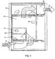
- FIG. 1schematically depicts an airflow through a chassis
- FIG. 2schematically illustrates airflow through a chassis including an airflow control assembly consistent with the present disclosure
- FIG. 3is a bottom view of a chassis including an airflow control assembly consistent with the present disclosure
- FIG. 4is a perspective view of an embodiment of an airflow control baffle assembly consistent with the present disclosure.
- FIG. 5is a perspective illustration of an airflow control baffle that may be used in connection with an airflow control baffle assembly consistent with the present disclosure.
- the chassis 102may include one or more circuit boards 107 disposed within the chassis 102 .
- the chassis 102may be an advanced telecommunications computing architecture (advanced TCA or ATCA) chassis, complying with, or compatible with, PCI Industrial Computer Manufacturers Group (PICMG), rev. 3.0, Advanced Telecommunications Computing Architecture (ATCA), published Dec. 30, 2002.
- the circuit board 107 disposed within the chassismay be an ATCA board, also referred to as an ATCA blade.
- one or more circuit boards 107may be configured to be coupled to one or more cards 109 , 111 .
- Cards 109 , 111may be either removably and/or permanently coupled to the circuit board 107 .
- the chassis 102may include an air cooling system including an air inlet region 101 , for example in a lower portion of the chassis 102 .
- the chassis 102may also have an air exhaust region 103 , which may, for example, be located in an upper portion of the chassis. Airflow through the chassis 102 may be induced by one or more fans 105 which may be positioned adjacent to the air exhaust region 103 of the chassis 102 .
- a convective cooling systemmay be a so-called ‘pull-through’ cooling system, in which the cooling air is drawn through the chassis 102 by the fan 105 .
- the cooling systemmay be a so-called ‘push-through’ cooling system in which the fan or fans may be positioned adjacent the air inlet region 101 . According to such a configuration, the fan or fans may draw air from the inlet region 101 and force the air into the chassis 102 , thereby at least partially pressurizing the chassis 102 and causing air to flow to, and out of, the air exhaust region 103 .
- the airflow through the chassis 102may have a distribution that may be largely determined by size and/or geometry of the chassis 102 and any boards and/or cards, etc. disposed within the chassis 102 .
- airflow distributionrefers to the flow of air from the air inlet region 101 , through the chassis 102 , and to the air exhaust region 103 .
- the airflow along any particular path between the air inlet 101 and the air exhaust 103may vary relative to any other particular path between the air inlet 101 and the air exhaust 103 .
- the airflow distribution of the chassis 102may include a relatively high airflow along a path generally through the center of the chassis 102 , as indicated by the larger arrow.
- the airflow to either side of this central regionmay be less than the airflow along the path generally through the center of the chassis, as indicated by the relatively smaller arrows.
- a chassismay have an airflow distribution different than the schematically illustrated airflow distribution. While the local airflow may vary for different paths through the chassis 102 , the overall airflow through the chassis 102 may generally be a function of the chassis layout and/or form factor, boards and/or cards disposed within the chassis, etc.
- the cooling effect experienced by components disposed within the chassis 102may be a function of the airflow distribution. That is, a component disposed in, or adjacent to, a relatively high airflow path, e.g. generally in the center of the chassis 102 , may experience a greater cooling effect as compared to components disposed in, or adjacent to relatively low airflow paths, e.g. to either side of the chassis 102 , in the illustrated schematic view. Accordingly, the cooling effect experienced by components within the chassis 102 may be, at least in part, dependent upon the location of such components within the chassis 102 .
- the airflow control system 100may be applied to computer or telecommunications equipment to selectively vary the airflow distribution through the chassis 102 of the equipment.
- the airflow distribution through the chassis 102may be selectively varied to provide increased and/or decreased airflow across various components and/or regions within the chassis 102 .
- the airflow across various portions of circuit board 107 and/or cards 109 and/or 111 disposed within the chassis 102may be controlled and/or varied.
- the airflow control system 100 hereinmay selectively vary the airflow distribution through the chassis 102
- the overall airflow rate through the chassis 102may be generally constant.
- an airflow control system 100may be employed in the context of an advanced telecommunications computing architecture (ATCA) environment system.
- the chassis 102may be an ATCA chassis, complying with, or being compatible with, ATCA specification.
- the airflow control system 100may be used in applications including confined spaces, such as single-board-computer blades like the Advanced TCA form factor.
- the airflow control system 100may include a baffle assembly 104 that may be disposed within the chassis 102 .
- the baffle assembly 104may be capable of providing an airflow resistance across the region of the baffle assembly 104 .
- the airflow resistance across the region of the baffle assembly 104may, in turn, affect the airflow resistance profile across the chassis 102 as a whole.
- the airflow resistance provided by the baffle assembly 104may be considered in terms of relative airflow resistance as compared to other portions of the chassis 102 , and/or as compared to the airflow resistance experienced in the general region of the chassis 102 in the absence of the baffle assembly 104 .
- the relative airflow resistance provided by the baffle assembly 104may be considered in terms of absolute airflow.
- the baffle assembly 104is disposed adjacent to an air inlet region 101 of the chassis 102 .
- the airflow resistance provided by the baffle assembly 104may alter the airflow resistance across the chassis 102 .
- the altered airflow resistance across the chassis 102may, in turn, alter the airflow distribution of air flowing through the chassis 102 . Consistent with the illustrated embodiment, at least a portion of the airflow into the chassis 102 may encounter the baffle assembly 104 .
- the baffle assembly 104may alter the airflow distribution through the chassis 102 .
- the baffle assemblymay provide an airflow distribution having a relatively small airflow through the center of the chassis 102 and may have an airflow adjacent either side of the chassis that is relatively large compared to the airflow through the center of the chassis 102 .
- This airflow distributionis in comparison to the relatively large airflow in the center of the chassis 102 and the relatively smaller airflows to either side of the chassis 102 illustrated in FIG. 1 .
- Numerous other airflow distributionsmay be achieved utilizing a baffle assembly 104 providing different relative airflow resistance at different locations in the chassis 102 .
- heat generating components 108 , 110may be disposed within the chassis 102 .
- Such heat generating components 108 , 110may include, for example, processors, chipsets, etc.
- Heat generating componentsmay be disposed on a printed circuit board disposed within the chassis, such as the illustrated heat generating component 108 disposed on the ATCA circuit board 107 .
- heat generating componentsmay be disposed on other features within the chassis 102 , such as the illustrated heat generating component 110 disposed on the card 109 coupled to the circuit board 107 .
- Heat generating componentsmay additionally, or alternatively, be disposed on and/or associated with other components or features disposed at least partially within the chassis 102 .
- the baffle assembly 104may be configured to customize the airflow distribution through the chassis 102 in a manner to increase airflow in regions including and/or adjacent to heat generating components 108 , 110 .
- the increased airflow in the regions including and/or adjacent to the heat generating components 108 , 110may increase the cooling of the heat generating components 108 , 110 as compared to a chassis 102 not including a baffle assembly 104 .
- the ability to customize the airflow distribution through the chassis 102 using a baffle assembly 104may increase the freedom of design of components to be disposed within the chassis 102 .
- heat generating components 108 , 110may be positioned based on desired PCB layout and/or routing considerations.
- the airflow distribution in the illustrated embodiment of FIG. 2includes airflows adjacent either side of the chassis 102 being at least slightly larger than the airflow through the center of the chassis 102 , this airflow distribution is provided to illustrate that the airflow distribution through the chassis 102 may be customized to provide greater airflow across heat generating components 108 , 110 .
- Other airflow distributionsmay be achieved by providing a baffle assembly 104 which has different airflow resistances and/or different airflow resistances at different regions or zones of the baffle assembly.
- an airflow control system 100may be configured to generally provide a more balanced and/or even airflow distribution through the chassis 102 .
- the baffle assembly 104may be configured to provide generally uniform airflow across the chassis 102 .
- the airflow resistancemay be generally uniform across the baffle assembly 104 .
- the airflow resistancemay vary for different regions of the baffle assembly 104 .
- the baffle assembly 104may include a plurality of zones 112 , 114 , 116 .
- the first zone 112may have a first airflow resistance
- the second zone 114may have a second airflow resistance
- the third zone 116may have a third airflow resistance.
- the airflow resistance of one or more of the first 112 , second 114 , and/or third 116 zonesmay be different from one or more of the other zones 112 , 114 , 116 .
- the airflow resistance of one or more of the zones 112 , 114 , 116may be the same as the airflow resistance through one or more of the other zones 112 , 114 , 116 .
- the illustrated airflow control system 100is shown including three zones 112 , 114 , 116 , consistent with the present disclosure the airflow control system 100 may include a greater or a lesser number of zones.
- An airflow control system 100 utilizing a baffle assembly 104 having multiple zones 112 , 114 , 116may allow the airflow distribution to be customized to a greater extent.
- the airflow distribution across the chassis 102may be customized to a greater extent as a result of the airflow resistance provided by each zone 112 , 114 , 116 of the baffle assembly 104 .
- the airflow distribution across the baffle assembly 104may also be customized.
- the airflow resistance of each zone 112 , 114 , 116may be individually controlled, independently of the other zones 112 , 114 , 116 . This aspect may permit variation in the airflow distribution across the baffle assembly 104 and/or may allow the airflow distribution across the chassis 102 to be customized to a greater extent.
- a baffle assemblymay include only a single zone providing an airflow resistance.
- the single baffle according to such an embodimentmay be positioned in a location within the airflow through the chassis.
- the presence of the baffle at the location within the airflow stream through the chassismay alter the airflow distribution through the chassis. For example, in a chassis having a low airflow resistance in a central region, as compared to other regions of the chassis, the airflow through the chassis may be greatest in the central region, as shown in FIG. 1 .
- a single baffle providing a degree of airflow resistancemay be positioned at least partially within the central, or low airflow resistance, region of the chassis.
- the presence of the baffle extending at least partially in to the central low airflow resistance region of the chassismay increase the airflow resistance through the central region of the chassis based on the airflow resistance of the baffle.
- the increase in airflow resistance in the central region of the chassismay increase the airflow in the surrounding regions of the chassis.
- the increased airflow in the surrounding regions of the chassismay increase the cooling of such regions.
- FIG. 3a bottom view of an embodiment of an airflow control system 100 a consistent with the present disclosure is shown.
- the baffle assembly 104 acan be seen having three zones 112 a , 114 a , 116 a .
- each zone 112 a , 114 a , 116 a of the baffle assembly 104 ais shown having a different flow resistance.
- the different flow resistances of each zone 112 a , 114 a , 116 a of the illustrated baffle assembly 104 amay be achieved by providing a different free-area ratio through the various zones 112 a , 114 a , 116 a .
- the free-area ratiois the ratio of the area that is open to permit airflow through the zone relative to the total cross-sectional area of the zone perpendicular to the airflow path through the zone 112 a , 114 a , 116 a.
- Each of the zones 112 a , 114 a , 116 a of the baffle assembly 104 amay include at least one baffle 120 a , 122 a , 124 a respectively.
- the desired airflow resistance of each of the zones 112 a , 114 a , 116 amay be achieved by providing openings or holes through the baffles 120 a , 122 a , 124 a .
- the openings or holes through the baffles 120 a , 122 a , 124 amay provide desired free-area ratios to achieved the desired airflow resistance.
- each baffle 120 a , 122 a , 124 amay be configured to provide a desired airflow resistance through each respective baffle 120 a , 122 a , 124 a.
- a first zone 112 ais provided having the greatest airflow resistance.
- the relatively high airflow resistance of the first zone 112 amay be achieved by providing a baffle 120 a not having any openings or holes extending through the baffle 120 a .
- the baffle 120 amay be considered to have a 0% free-area ratio.
- a second zone 114 amay have a baffle 122 a including a first array of holes 123 extending through the baffle providing an intermediate airflow resistance.
- the first array of holes 123may have a collective area that is equal to about 20% of the area of the baffle 122 a .
- a third zone 116 amay have a low airflow resistance as compared to the first and second zones 112 a , 114 a .
- the low airflow resistance of the third zone 116 amay be achieved by providing a baffle 124 a having a second array of holes 125 .
- the second array of holes 125may account for approximately 70% of the area of the baffle 124 a , providing a 70% free-area ratio for the third zone 116 a.
- each of the zones of a baffle assembly 104 a consistent with the present disclosuremay be provided having a free-area ratio of 0% to 100%, inclusive.
- a 0% free-area ratiomay be achieved by completely obstructing airflow through the zone and/or by providing a baffle not having any openings extending therethrough.
- a 100% free-area ratiomay by achieved by eliminating airflow obstructions through the zone and/or by providing a zone that does not include a baffle extending into the airflow pathway.
- baffle assembly 104 amay comprise the form factor of a card that can be received in the chassis 102 .
- the baffle assembly 104 amay be configured within the form factor of a card that may be coupled to a circuit board 107 that is disposed within the chassis 102 .
- baffle assemblymay be coupled to other components within the chassis and/or to the chassis, without departing from this embodiment.
- the baffle assembly 104 amay comprise the form factor of a mezzanine card.
- the baffle assembly 104 amay be coupled to an unpopulated slot on the ATCA board 107 disposed within the chassis 102 .
- the baffle assembly 104 amay be a dummy card.
- a “dummy card” as used herein,may comprise a baffle assembly 104 a may be coupled to a circuit board 107 in a card slot of the circuit board 107 , and may be devoid of other circuitry and/or electronics interacting with the circuit board 107 .
- the baffle assembly 104 amay include a body or base plate 127 .
- the baffle assemblymay further include one or more tabs 129 for coupling the baffle assembly 104 a to a circuit board 107 .
- the baffle assembly 104 amay include circuitry or electronics that may interact with the circuit board 107 .
- the base plate 127may be a circuit board, etc., including circuitry and/or electronics configured to be coupled to the circuit board 107 and to interact with the circuit board 107 .
- one or more tabs 129may couple the baffle assemble 104 a to other components within the chassis 102 , and/or to the chassis 102 itself.
- the baffle assembly 104 amay be configured having more than one zone 112 a , 114 a , 116 a .
- the zones 112 a , 114 a , 116 amay be separated by partitions 113 , 115 disposed between adjacent zones 112 a , 114 a and 114 a , 116 a respectively.
- the partitions 113 , 115may provide separate airflow paths for each of the zones 112 a , 114 a , 116 a .
- the height of the partitionsmay also be configured within the form factor of such a card.
- the height of the partitionsmay be configured to take advantage of the full available depth of the chassis 102 .
- the baffle assembly 104 amay be provided having more than one baffle 124 a , 126 , 128 , 130 associated with each zone 116 a .
- Each of the baffles 124 a , 126 , 128 , 130 in the zone 116 amay be configured to provide a different airflow resistance.
- each of the baffles 124 a , 126 , 128 , 130may be provided having a different free-area ratio.
- the various baffles 124 a , 126 , 128 , 130may be configured to be selectively deployable within the zone 116 a of the baffle assembly 104 a .
- a desired airflow resistance of the zone 116 amay, therefore, be achieved by deploying a baffle 124 a , 126 , 128 , 130 having a free-area ratio selected to provide the desired airflow resistance.
- the remaining zones 112 a , 114 amay have a generally analogous structure.
- the baffles 124 a , 126 , 128 , 130may be movable between a stowed configuration and a deployed configuration. In a stowed configuration the baffles 126 , 128 , 130 may be generally oriented to impart a minimal influence on the airflow resistance through the zone 116 a . In the illustrated embodiment, in a stowed configuration the baffles 126 , 128 , 130 may be disposed lying generally flat against the base plate 127 of the baffle assembly 104 a . In a deployed configuration, a baffle 124 a may be oriented to influence the airflow resistance through the zone 116 a . In the illustrated embodiment, when a baffle 124 a is in a deployed configuration the baffle 124 a may be oriented in a generally upright arrangement within an airflow passage defined by the zone 116 a.
- the baffle assembly 104 amay be customized to provide various different desired airflow resistances.
- each of the zones 112 a , 114 a , 116 amay be customized by selectively deploying baffles providing desired airflow resistances in each of the zones 112 a , 114 a , 116 a . While the selection of different baffles associated with each zone is shown as being generally the same in terms of free-area ratios, this is not necessary. Any or all of the zones may include one or more baffles having free-area ratios that are different than the free-area ratios of one or more of the baffles associated with any, or all, of the other zones.
- the baffle 124 amay generally include a plate 132 having a plurality of holes 134 extending therethrough.
- the number and size of the holes 134may be selected to achieve a desired airflow resistance.
- the desired airflow resistancemay be achieved by providing a corresponding free-area ratio of the baffle 124 a .
- a given free-area ratiomay, however, provide different airflow resistances depending upon the shape, size, and location of the individual holes 134 . Accordingly, it is not necessary for there to be an absolute correlation between airflow resistance and free-area ratio.
- the baffle 124 amay be configured to be pivotally movable between the stowed configuration and the deployed configuration. As shown, pivotal movement may be facilitated by providing pivots 136 , 138 extending from opposed edges 140 , 142 of the baffle 124 a .
- the pivots 136 - 138may be formed as bosses extending from the opposed edges 140 , 142 of the baffle 124 a .
- the pivots 136 , 138may be configured to pivotally engage cooperating features on the baffle assembly 104 a , such as holes or indentations.
- the baffle 124 amay be secured in a deployed configuration and/or in a stowed configuration using cooperating features on the baffle 124 a and the baffle assembly 104 a .
- the baffle 124 amay include detents 144 , 146 also protruding from the opposed sides 140 , 142 of the baffle 124 a .
- the detents 144 , 146may engage cooperating indentations, e.g., 148 on the baffle assembly 104 a .
- Other featuresmay be used to achieve pivotal movement of the baffle 124 a and/or to secure the baffle 124 a in a stowed configuration and/or a deployed configuration.
- the above-described baffle assembly 104 aincluding the baffles 120 a , 122 a , 124 a , 126 , 128 , 130 , partitions 113 , 115 , etc. may be produced using low cost manufacturing processes.
- the baffles 120 a , 122 a , 124 a , 126 , 128 , 130 and/or the body and/or other components of the baffle assembly 104 amay be produced from plastic materials using conventional forming techniques such as injection molding, die cutting, etc.
- Alternative, and/or additional, materials and manufacturing processes and techniquesmay also be used for producing a baffle assembly consistent with the present disclosure.
- the baffle assembly 104 amay provide a cost effective system for controlling the airflow through a chassis.
- the ability to control the airflow through the chassismay, as previously discussed, may improve the performance of the system and increase the freedom with which heat generating components may be located within the chassis.
- a single baffle including a selectable free-area ratiomay be provided.
- a bafflemay be provided having a plurality of removable obstructions. The removable obstructions may be selectively removed to provide a desired airflow resistance.
- a bafflemay be provided having a plurality of knock-outs. The airflow resistance of the baffle may be decreased by removing a greater number of knock-outs from the baffle.
- the bafflemay easily be formed including one, or a plurality, of regions bounded by lines of mechanical weakness allowing the regions to be removed from the baffle.
- each zonemay include an arrangement for providing a variable airflow through each respective zone.
- Such an arrangementmay include, for example, a damper for controlling the airflow relative to at least a portion of the baffle assembly.
- a movable membermay be moved between a first position providing a first airflow resistance and a second position providing a second airflow resistance that is greater than the first airflow resistance.
- the movable membermay include a screen that may be moved into a position at least partially obstructing airflow through one or more zone of the baffle assembly.
- a baffle having a first free-area ratiomay be provided.
- the screenmay be moved between a first position obstructing a first degree of the free-area of the baffle and a second position obstructing a second, greater, amount of the free-area of the baffle.
- the screenmay be provided as a sliding screen that may be slidable moved between the first position and the second position.
- a bafflemay be provided having one opening, or a plurality of openings, extending therethrough providing a first free-area ratio.
- the bafflemay further include a movable obstruction that may be adjusted to reduce the free-area of the opening, or openings, through the baffle.
- the movable obstructionmay include one or more openings that may, in a first position, be at least partially aligned with one or more openings in the baffle, thereby providing a first free-area ratio of the baffle.
- the obstructionmay be moved to at least a second position in which the opening in the movable obstruction at least partially blocks at least one opening in the baffle thereby providing a second free-area ratio of the baffle that is less than the first free-area ratio of the baffle.
- the movable obstructionmay be linearly movable and/or rotationally movable between the first position and the second position.
- a movable obstruction hereinmay be moved between a first position and a second position manually and/or using an actuator, such as a solenoid, servo, or other mechanical and/or electromechanical actuator.
- the airflow control systemmay include a feedback control.
- the temperature of at least one component and/or the temperature of at least a portion of the airflow stream within the chassismay be measured.
- the airflow resistance through the chassismay be controlled and/or adjusted, for example using a baffle assembly configured to provide variable airflow resistance, in response to the measured temperature.
- the airflow resistance of the baffle assemblymay be adjusted, e.g. using an electromechanical actuator, to increase the airflow in the region of, or adjacent to, the heat generating or heat sensitive component.
- the feedback controlmay adjust the variable airflow resistance baffle assemble to decrease the airflow in the region of, or adjacent to, the heat generating or heat sensitive component.
Landscapes
- Engineering & Computer Science (AREA)
- Theoretical Computer Science (AREA)
- Human Computer Interaction (AREA)
- Physics & Mathematics (AREA)
- General Engineering & Computer Science (AREA)
- General Physics & Mathematics (AREA)
- Cooling Or The Like Of Electrical Apparatus (AREA)
- Air-Conditioning For Vehicles (AREA)
- Air-Flow Control Members (AREA)
Abstract
Description
Claims (14)
Priority Applications (1)
| Application Number | Priority Date | Filing Date | Title |
|---|---|---|---|
| US12/686,255US7864541B2 (en) | 2004-12-06 | 2010-01-12 | Airflow control system |
Applications Claiming Priority (2)
| Application Number | Priority Date | Filing Date | Title |
|---|---|---|---|
| US11/005,910US7652891B2 (en) | 2004-12-06 | 2004-12-06 | Airflow control system |
| US12/686,255US7864541B2 (en) | 2004-12-06 | 2010-01-12 | Airflow control system |
Related Parent Applications (1)
| Application Number | Title | Priority Date | Filing Date |
|---|---|---|---|
| US11/005,910ContinuationUS7652891B2 (en) | 2004-12-06 | 2004-12-06 | Airflow control system |
Publications (2)
| Publication Number | Publication Date |
|---|---|
| US20100118490A1 US20100118490A1 (en) | 2010-05-13 |
| US7864541B2true US7864541B2 (en) | 2011-01-04 |
Family
ID=36573920
Family Applications (2)
| Application Number | Title | Priority Date | Filing Date |
|---|---|---|---|
| US11/005,910Expired - LifetimeUS7652891B2 (en) | 2004-12-06 | 2004-12-06 | Airflow control system |
| US12/686,255Expired - Fee RelatedUS7864541B2 (en) | 2004-12-06 | 2010-01-12 | Airflow control system |
Family Applications Before (1)
| Application Number | Title | Priority Date | Filing Date |
|---|---|---|---|
| US11/005,910Expired - LifetimeUS7652891B2 (en) | 2004-12-06 | 2004-12-06 | Airflow control system |
Country Status (4)
| Country | Link |
|---|---|
| US (2) | US7652891B2 (en) |
| CN (1) | CN1787734A (en) |
| TW (1) | TW200626848A (en) |
| WO (1) | WO2006062730A2 (en) |
Cited By (9)
| Publication number | Priority date | Publication date | Assignee | Title |
|---|---|---|---|---|
| US20120214401A1 (en)* | 2011-02-17 | 2012-08-23 | Hon Hai Precision Industry Co., Ltd. | Airflow guide cover |
| US20130265713A1 (en)* | 2012-04-05 | 2013-10-10 | Robert Lee Crane | Daughterboard having airflow path |
| US20170084516A1 (en)* | 2014-07-07 | 2017-03-23 | Toshiba Mitsubishi-Electric Industrial Systems Corporation | Semiconductor apparatus |
| US20170347495A1 (en)* | 2016-05-27 | 2017-11-30 | Cisco Technology, Inc. | Blank card with scalable airflow impedance for electronic enclosures |
| US9915987B2 (en) | 2015-02-02 | 2018-03-13 | International Business Machines Corporation | Implementing DIMM air flow baffle |
| US10037062B1 (en) | 2017-03-17 | 2018-07-31 | Microsoft Technology Licensing, Llc | Thermal venting device with pressurized plenum |
| US20180299932A1 (en)* | 2017-04-17 | 2018-10-18 | EMC IP Holding Company LLC | Chassis and heat sink for use in chassis |
| US20190045659A1 (en)* | 2017-08-01 | 2019-02-07 | Dell Products L.P. | Flexible service air baffle |
| US10244666B2 (en)* | 2014-02-14 | 2019-03-26 | Hewlett Packard Enterprise Development Lp | Controlling impedance of blank cartridges |
Families Citing this family (29)
| Publication number | Priority date | Publication date | Assignee | Title |
|---|---|---|---|---|
| US7652891B2 (en) | 2004-12-06 | 2010-01-26 | Radisys Corporation | Airflow control system |
| WO2008003038A2 (en)* | 2006-06-29 | 2008-01-03 | Se2 Labs | Systems and methods for improved cooling of lelectrical components |
| JP2008166375A (en)* | 2006-12-27 | 2008-07-17 | Nec Corp | Plug-in unit and electronic equipment |
| US20080218969A1 (en)* | 2007-03-09 | 2008-09-11 | Sony Corporation | Electronic system with adjustable venting system |
| US9017154B2 (en)* | 2007-07-13 | 2015-04-28 | Dell Products L.P. | Chassis having an internal air plenum and an arrangement of multiple chassis to form a vertical air plenum |
| US7646600B2 (en)* | 2008-04-15 | 2010-01-12 | International Business Machines Corporation | Structural support module to prevent common interface deflection |
| US7885066B2 (en)* | 2008-07-17 | 2011-02-08 | Juniper Networks, Inc. | Airflow/cooling solution for chassis with orthogonal boards |
| US10321601B2 (en)* | 2008-10-17 | 2019-06-11 | Artesyn Embedded Computing, Inc. | System and method for restricting airflow through a portion of an electronics enclosure |
| US8363388B2 (en)* | 2008-10-17 | 2013-01-29 | Emerson Network Power—Embedded Computing, Inc. | System and method for supplying power to electronics enclosures utilizing distributed DC power architectures |
| US20100216390A1 (en)* | 2008-10-17 | 2010-08-26 | Emerson Network Power - Embedded Computing, Inc. | Apparatus and Method for Restricting Air Flow Within an Electronic Equipment Enclosure |
| US20100218920A1 (en)* | 2008-10-17 | 2010-09-02 | Emerson Network Power - Embedded Computing, Inc. | System And Method For Airflow Dividers For Use With Cooling Systems For An Equipment Enclosure |
| US20100159816A1 (en)* | 2008-12-23 | 2010-06-24 | International Business Machines Corporation | Converging segments cooling |
| US7903405B1 (en)* | 2009-09-18 | 2011-03-08 | Fisher-Rosemount Systems, Inc. | Electronic device enclosures having improved ventilation to dissipate heat |
| FR2954971B1 (en)* | 2010-01-06 | 2012-02-10 | Paul Benoit | ELECTRICAL RADIATOR USING CALCULATING PROCESSORS AS HOT SOURCE. |
| US20110228475A1 (en)* | 2010-03-17 | 2011-09-22 | International Business Machines Corporation | Enclosure with concurrently maintainable field replaceable units |
| US8446725B2 (en)* | 2010-08-05 | 2013-05-21 | Alcatel Lucent | Airflow control in an electronic chassis |
| CN102480895A (en)* | 2010-11-22 | 2012-05-30 | 鸿富锦精密工业(深圳)有限公司 | Electronic device and wind scooper thereof |
| TW201309179A (en)* | 2011-08-04 | 2013-02-16 | Wistron Corp | Airflow adjusting device and blade server |
| EP2836057B1 (en)* | 2013-08-09 | 2019-07-17 | British Telecommunications public limited company | Ventilation system |
| US9788461B2 (en)* | 2014-07-30 | 2017-10-10 | Ciena Corporation | Airflow divider for balancing airflow in a modular chassis system |
| US9949407B1 (en)* | 2015-05-29 | 2018-04-17 | Amazon Technologies, Inc. | Computer system with partial bypass cooling |
| US10373169B2 (en)* | 2015-08-11 | 2019-08-06 | Paypal, Inc. | Enhancing information security via the use of a dummy credit card number |
| US10403328B2 (en)* | 2016-01-29 | 2019-09-03 | Western Digital Technologies, Inc. | Acoustic attenuation in data storage enclosures |
| US10838470B1 (en)* | 2017-02-17 | 2020-11-17 | American Megatrends International, Llc | Monitoring temperature inside computer chassis |
| US10627877B2 (en) | 2017-03-31 | 2020-04-21 | Hewlett Packard Enterprise Development Lp | Air impeding structures with snap-in tabs |
| CN112445299B (en)* | 2019-09-05 | 2023-03-10 | 英业达科技有限公司 | Expansion card holder |
| EP4075931A4 (en)* | 2020-01-23 | 2023-06-14 | Huawei Technologies Co., Ltd. | OUTER LID OF AN ELECTRONIC DEVICE AND ELECTRONIC DEVICE COMPONENT |
| CN112236018A (en)* | 2020-11-05 | 2021-01-15 | 阳光电源股份有限公司 | Power cabinet and converter |
| US20250240908A1 (en)* | 2024-01-19 | 2025-07-24 | Dell Products L.P. | Universal airflow impedance blank with adjustable venting ratio |
Citations (23)
| Publication number | Priority date | Publication date | Assignee | Title |
|---|---|---|---|---|
| US4894749A (en) | 1987-08-31 | 1990-01-16 | AT&T Information Systems Inc American Telephone and Telegraph Company | Option slot filler board |
| US5210680A (en) | 1990-08-07 | 1993-05-11 | Sulzer Brothers Limited | Card cage having an air cooling system |
| US5613906A (en) | 1995-07-20 | 1997-03-25 | Elonex I.P. Holdings, Ltd. | Method and apparatus for waste heat removal from a computer enclosure |
| US5914858A (en) | 1997-11-13 | 1999-06-22 | Northern Telecom Limited | Baffle arrangement for an airflow balance system |
| US5995368A (en) | 1998-10-20 | 1999-11-30 | Nortel Networks Corporation | Air flow distribution device for shelf-based circuit cards |
| US6005770A (en) | 1997-11-12 | 1999-12-21 | Dell U.S.A., L.P. | Computer and a system and method for cooling the interior of the computer |
| US6031717A (en) | 1999-04-13 | 2000-02-29 | Dell Usa, L.P. | Back flow limiting device for failed redundant parallel fan |
| US6047836A (en) | 1997-07-23 | 2000-04-11 | Tektronix, Inc. | Card guide with airflow shutters |
| US6151213A (en) | 1999-05-12 | 2000-11-21 | 3Com Corporation | Ventilation and cooling control system for modular platforms |
| US6285548B1 (en) | 2000-08-18 | 2001-09-04 | Quantum Bridge Communications, Inc. | Face plate for a chassis for high frequency components |
| US6407331B1 (en) | 2001-03-21 | 2002-06-18 | Eaton Corporation | Pressure relief panel for arc resistant cabinets |
| US20030141089A1 (en) | 2002-01-30 | 2003-07-31 | Gravell Anthony R. | Balanced flow cooling |
| US6710240B1 (en) | 2003-04-24 | 2004-03-23 | Datech Technology Co., Ltd. | Register incorporating a toggle-joint mechanism between open and closed position |
| US20040057210A1 (en) | 2002-09-20 | 2004-03-25 | Wilson Jeremy I. | Composite construction baffle for modular electronic systems |
| US6738262B2 (en) | 2001-05-21 | 2004-05-18 | Sycamore Networks, Inc. | Port filler baffle |
| US20040218359A1 (en) | 2003-04-30 | 2004-11-04 | Hewlett-Parckard Development Company, L.P. | Circuit card divider to facilitate thermal management in an electronic system |
| US6912131B2 (en) | 2003-08-27 | 2005-06-28 | Lucent Technologies Inc. | Electronic components card air deflector |
| US6980435B2 (en) | 2004-01-28 | 2005-12-27 | Hewlett-Packard Development Company, L.P. | Modular electronic enclosure with cooling design |
| WO2006062730A2 (en) | 2004-12-06 | 2006-06-15 | Intel Corporation | Airflow control system |
| US7259961B2 (en) | 2004-06-24 | 2007-08-21 | Intel Corporation | Reconfigurable airflow director for modular blade chassis |
| US7355850B2 (en) | 2006-03-31 | 2008-04-08 | National Instruments Corporation | Vented and ducted sub-rack support member |
| US7394654B2 (en) | 2006-10-19 | 2008-07-01 | Cisco Technology, Inc. | Method and apparatus for providing thermal management in an electronic device |
| US7420806B1 (en) | 2005-11-22 | 2008-09-02 | Juniper Networks, Inc. | Airflow distribution through an electronic device |
- 2004
- 2004-12-06USUS11/005,910patent/US7652891B2/ennot_activeExpired - Lifetime
- 2005
- 2005-11-17WOPCT/US2005/042254patent/WO2006062730A2/enactiveApplication Filing
- 2005-11-21TWTW094140831Apatent/TW200626848A/enunknown
- 2005-12-02CNCN200510127713.5Apatent/CN1787734A/enactivePending
- 2010
- 2010-01-12USUS12/686,255patent/US7864541B2/ennot_activeExpired - Fee Related
Patent Citations (25)
| Publication number | Priority date | Publication date | Assignee | Title |
|---|---|---|---|---|
| US4894749A (en) | 1987-08-31 | 1990-01-16 | AT&T Information Systems Inc American Telephone and Telegraph Company | Option slot filler board |
| US5210680A (en) | 1990-08-07 | 1993-05-11 | Sulzer Brothers Limited | Card cage having an air cooling system |
| US5613906A (en) | 1995-07-20 | 1997-03-25 | Elonex I.P. Holdings, Ltd. | Method and apparatus for waste heat removal from a computer enclosure |
| US6047836A (en) | 1997-07-23 | 2000-04-11 | Tektronix, Inc. | Card guide with airflow shutters |
| US6005770A (en) | 1997-11-12 | 1999-12-21 | Dell U.S.A., L.P. | Computer and a system and method for cooling the interior of the computer |
| US5914858A (en) | 1997-11-13 | 1999-06-22 | Northern Telecom Limited | Baffle arrangement for an airflow balance system |
| US5995368A (en) | 1998-10-20 | 1999-11-30 | Nortel Networks Corporation | Air flow distribution device for shelf-based circuit cards |
| US6031717A (en) | 1999-04-13 | 2000-02-29 | Dell Usa, L.P. | Back flow limiting device for failed redundant parallel fan |
| US6151213A (en) | 1999-05-12 | 2000-11-21 | 3Com Corporation | Ventilation and cooling control system for modular platforms |
| US6285548B1 (en) | 2000-08-18 | 2001-09-04 | Quantum Bridge Communications, Inc. | Face plate for a chassis for high frequency components |
| US6407331B1 (en) | 2001-03-21 | 2002-06-18 | Eaton Corporation | Pressure relief panel for arc resistant cabinets |
| US6738262B2 (en) | 2001-05-21 | 2004-05-18 | Sycamore Networks, Inc. | Port filler baffle |
| US20030141089A1 (en) | 2002-01-30 | 2003-07-31 | Gravell Anthony R. | Balanced flow cooling |
| US20040057210A1 (en) | 2002-09-20 | 2004-03-25 | Wilson Jeremy I. | Composite construction baffle for modular electronic systems |
| US6710240B1 (en) | 2003-04-24 | 2004-03-23 | Datech Technology Co., Ltd. | Register incorporating a toggle-joint mechanism between open and closed position |
| US20040218359A1 (en) | 2003-04-30 | 2004-11-04 | Hewlett-Parckard Development Company, L.P. | Circuit card divider to facilitate thermal management in an electronic system |
| US6922337B2 (en) | 2003-04-30 | 2005-07-26 | Hewlett-Packard Development Company, L.P. | Circuit card divider to facilitate thermal management in an electronic system |
| US6912131B2 (en) | 2003-08-27 | 2005-06-28 | Lucent Technologies Inc. | Electronic components card air deflector |
| US6980435B2 (en) | 2004-01-28 | 2005-12-27 | Hewlett-Packard Development Company, L.P. | Modular electronic enclosure with cooling design |
| US7259961B2 (en) | 2004-06-24 | 2007-08-21 | Intel Corporation | Reconfigurable airflow director for modular blade chassis |
| WO2006062730A2 (en) | 2004-12-06 | 2006-06-15 | Intel Corporation | Airflow control system |
| US7652891B2 (en)* | 2004-12-06 | 2010-01-26 | Radisys Corporation | Airflow control system |
| US7420806B1 (en) | 2005-11-22 | 2008-09-02 | Juniper Networks, Inc. | Airflow distribution through an electronic device |
| US7355850B2 (en) | 2006-03-31 | 2008-04-08 | National Instruments Corporation | Vented and ducted sub-rack support member |
| US7394654B2 (en) | 2006-10-19 | 2008-07-01 | Cisco Technology, Inc. | Method and apparatus for providing thermal management in an electronic device |
Non-Patent Citations (7)
| Title |
|---|
| International Search Report and Written Opinion of the International Searching Authority dated May 17, 2006, application PCT/US2005/042254, filed Nov. 17, 2005. |
| Notice of Allowance mailed Sep. 11, 2009, for U.S. Appl. No. 11/005,910, filed Dec. 6, 2004. |
| Office Action mailed Apr. 1, 2009, for U.S. Appl. No. 11/005,910, filed Dec. 6, 2004. |
| Office Action mailed Aug. 3, 2007, for U.S. Appl. No. 11/005,910, filed Dec. 6, 2004. |
| Office Action mailed Feb. 13, 2007, for U.S. Appl. No. 11/005,910, filed Dec. 6, 2004. |
| Office Action mailed Feb. 21, 2008, for U.S. Appl. No. 11/005,910, filed Dec. 6, 2004. |
| Office Action mailed Nov. 6, 2008, for U.S. Appl. No. 11/005,910, filed Dec. 6, 2004. |
Cited By (15)
| Publication number | Priority date | Publication date | Assignee | Title |
|---|---|---|---|---|
| US20120214401A1 (en)* | 2011-02-17 | 2012-08-23 | Hon Hai Precision Industry Co., Ltd. | Airflow guide cover |
| US20130265713A1 (en)* | 2012-04-05 | 2013-10-10 | Robert Lee Crane | Daughterboard having airflow path |
| US8848364B2 (en)* | 2012-04-05 | 2014-09-30 | Hewlett-Packard Development Company, L.P. | Daughterboard having airflow path |
| US10244666B2 (en)* | 2014-02-14 | 2019-03-26 | Hewlett Packard Enterprise Development Lp | Controlling impedance of blank cartridges |
| US20170084516A1 (en)* | 2014-07-07 | 2017-03-23 | Toshiba Mitsubishi-Electric Industrial Systems Corporation | Semiconductor apparatus |
| US10347561B2 (en)* | 2014-07-07 | 2019-07-09 | Toshiba Mitsubishi-Electric Industrial Systems Corporation | Semiconductor apparatus |
| US9921623B2 (en) | 2015-02-02 | 2018-03-20 | International Business Machines Corporation | Implementing DIMM air flow baffle |
| US9915987B2 (en) | 2015-02-02 | 2018-03-13 | International Business Machines Corporation | Implementing DIMM air flow baffle |
| US9949408B2 (en)* | 2016-05-27 | 2018-04-17 | Cisco Technology, Inc. | Blank card with scalable airflow impedance for electronic enclosures |
| US20170347495A1 (en)* | 2016-05-27 | 2017-11-30 | Cisco Technology, Inc. | Blank card with scalable airflow impedance for electronic enclosures |
| US10037062B1 (en) | 2017-03-17 | 2018-07-31 | Microsoft Technology Licensing, Llc | Thermal venting device with pressurized plenum |
| US20180299932A1 (en)* | 2017-04-17 | 2018-10-18 | EMC IP Holding Company LLC | Chassis and heat sink for use in chassis |
| US10672430B2 (en)* | 2017-04-17 | 2020-06-02 | EMC IP Holding Company LLC | Chassis and heat sink for use in chassis |
| US20190045659A1 (en)* | 2017-08-01 | 2019-02-07 | Dell Products L.P. | Flexible service air baffle |
| US11102910B2 (en)* | 2017-08-01 | 2021-08-24 | Dell Products L.P. | Flexible service air baffle |
Also Published As
| Publication number | Publication date |
|---|---|
| US20100118490A1 (en) | 2010-05-13 |
| US7652891B2 (en) | 2010-01-26 |
| WO2006062730A2 (en) | 2006-06-15 |
| CN1787734A (en) | 2006-06-14 |
| TW200626848A (en) | 2006-08-01 |
| US20060120038A1 (en) | 2006-06-08 |
| WO2006062730A3 (en) | 2006-08-03 |
Similar Documents
| Publication | Publication Date | Title |
|---|---|---|
| US7864541B2 (en) | Airflow control system | |
| US9894807B2 (en) | Changeable, airflow venting cover assembly for an electronics rack | |
| US5526875A (en) | Cooling device for CPU | |
| US7061761B2 (en) | System and method for cooling components in an electronic device | |
| US6975510B1 (en) | Ventilated housing for electronic components | |
| US6330155B1 (en) | Method and apparatus for temperature control of electrical devices mounted on circuit boards | |
| US7215552B2 (en) | Airflow redistribution device | |
| AU2002300007B2 (en) | Method and apparatus for controlling airflow | |
| TWI327192B (en) | Fan | |
| US9075581B2 (en) | Apparatus and method for cooling electrical components of a computer | |
| EP0977473B1 (en) | Electronic device cooling system having guides for guiding a flow of the air evenly | |
| US6735079B2 (en) | Heat dissipation apparatus | |
| CN101212892B (en) | Plug-in unit and electronic apparatus | |
| US6922337B2 (en) | Circuit card divider to facilitate thermal management in an electronic system | |
| CN101466249A (en) | Base device with medial plate design and method for cooling the device | |
| CN1782950B (en) | Portable computer power system | |
| US20070242428A1 (en) | Structure for fixing fan with computer casing | |
| US20050185376A1 (en) | Speaker grill-air vent combinations for a portable computer | |
| CN101795546A (en) | Subrack and heat radiating method thereof | |
| US12114462B2 (en) | Modular card cage accessories | |
| US9949408B2 (en) | Blank card with scalable airflow impedance for electronic enclosures | |
| US7581583B2 (en) | Heat dissipating device with adjusting member | |
| EP4002974B1 (en) | Device for airflow management and cooling improvement in hybrid-cooled electronics | |
| KR200493516Y1 (en) | Cooling apparatus for rack | |
| EP2479645A1 (en) | Keyboard module |
Legal Events
| Date | Code | Title | Description |
|---|---|---|---|
| AS | Assignment | Owner name:INTEL CORPORATION,CALIFORNIA Free format text:ASSIGNMENT OF ASSIGNORS INTEREST;ASSIGNORS:LUCERO, CHRISTOPHER D.;LEIJA, JAVIER;SHIPLEY, JAMES C.;AND OTHERS;REEL/FRAME:023824/0344 Effective date:20050121 Owner name:RADISYS CORPORATION,OREGON Free format text:ASSIGNMENT OF ASSIGNORS INTEREST;ASSIGNOR:INTEL CORPORATION;REEL/FRAME:023824/0415 Effective date:20070912 Owner name:INTEL CORPORATION, CALIFORNIA Free format text:ASSIGNMENT OF ASSIGNORS INTEREST;ASSIGNORS:LUCERO, CHRISTOPHER D.;LEIJA, JAVIER;SHIPLEY, JAMES C.;AND OTHERS;REEL/FRAME:023824/0344 Effective date:20050121 Owner name:RADISYS CORPORATION, OREGON Free format text:ASSIGNMENT OF ASSIGNORS INTEREST;ASSIGNOR:INTEL CORPORATION;REEL/FRAME:023824/0415 Effective date:20070912 | |
| REMI | Maintenance fee reminder mailed | ||
| FPAY | Fee payment | Year of fee payment:4 | |
| SULP | Surcharge for late payment | ||
| AS | Assignment | Owner name:HCP-FVG, LLC, NEW YORK Free format text:SECURITY INTEREST;ASSIGNORS:RADISYS CORPORATION;RADISYS INTERNATIONAL LLC;REEL/FRAME:044995/0671 Effective date:20180103 | |
| AS | Assignment | Owner name:MARQUETTE BUSINESS CREDIT, LLC, CALIFORNIA Free format text:SECURITY INTEREST;ASSIGNOR:RADISYS CORPORATION;REEL/FRAME:044540/0080 Effective date:20180103 | |
| FEPP | Fee payment procedure | Free format text:MAINTENANCE FEE REMINDER MAILED (ORIGINAL EVENT CODE: REM.); ENTITY STATUS OF PATENT OWNER: LARGE ENTITY | |
| LAPS | Lapse for failure to pay maintenance fees | Free format text:PATENT EXPIRED FOR FAILURE TO PAY MAINTENANCE FEES (ORIGINAL EVENT CODE: EXP.); ENTITY STATUS OF PATENT OWNER: LARGE ENTITY | |
| STCH | Information on status: patent discontinuation | Free format text:PATENT EXPIRED DUE TO NONPAYMENT OF MAINTENANCE FEES UNDER 37 CFR 1.362 | |
| FP | Lapsed due to failure to pay maintenance fee | Effective date:20190104 |