US7864270B2 - Electronic device and LC shutter with diffusive reflective polarizer - Google Patents
Electronic device and LC shutter with diffusive reflective polarizerDownload PDFInfo
- Publication number
- US7864270B2 US7864270B2US12/028,092US2809208AUS7864270B2US 7864270 B2US7864270 B2US 7864270B2US 2809208 AUS2809208 AUS 2809208AUS 7864270 B2US7864270 B2US 7864270B2
- Authority
- US
- United States
- Prior art keywords
- polarizer
- shutter
- dichroic polarizer
- dichroic
- cell
- Prior art date
- Legal status (The legal status is an assumption and is not a legal conclusion. Google has not performed a legal analysis and makes no representation as to the accuracy of the status listed.)
- Expired - Fee Related, expires
Links
Images


Classifications
- G—PHYSICS
- G02—OPTICS
- G02F—OPTICAL DEVICES OR ARRANGEMENTS FOR THE CONTROL OF LIGHT BY MODIFICATION OF THE OPTICAL PROPERTIES OF THE MEDIA OF THE ELEMENTS INVOLVED THEREIN; NON-LINEAR OPTICS; FREQUENCY-CHANGING OF LIGHT; OPTICAL LOGIC ELEMENTS; OPTICAL ANALOGUE/DIGITAL CONVERTERS
- G02F1/00—Devices or arrangements for the control of the intensity, colour, phase, polarisation or direction of light arriving from an independent light source, e.g. switching, gating or modulating; Non-linear optics
- G02F1/01—Devices or arrangements for the control of the intensity, colour, phase, polarisation or direction of light arriving from an independent light source, e.g. switching, gating or modulating; Non-linear optics for the control of the intensity, phase, polarisation or colour
- G02F1/13—Devices or arrangements for the control of the intensity, colour, phase, polarisation or direction of light arriving from an independent light source, e.g. switching, gating or modulating; Non-linear optics for the control of the intensity, phase, polarisation or colour based on liquid crystals, e.g. single liquid crystal display cells
- G02F1/133—Constructional arrangements; Operation of liquid crystal cells; Circuit arrangements
- G02F1/13306—Circuit arrangements or driving methods for the control of single liquid crystal cells
- G—PHYSICS
- G02—OPTICS
- G02F—OPTICAL DEVICES OR ARRANGEMENTS FOR THE CONTROL OF LIGHT BY MODIFICATION OF THE OPTICAL PROPERTIES OF THE MEDIA OF THE ELEMENTS INVOLVED THEREIN; NON-LINEAR OPTICS; FREQUENCY-CHANGING OF LIGHT; OPTICAL LOGIC ELEMENTS; OPTICAL ANALOGUE/DIGITAL CONVERTERS
- G02F1/00—Devices or arrangements for the control of the intensity, colour, phase, polarisation or direction of light arriving from an independent light source, e.g. switching, gating or modulating; Non-linear optics
- G02F1/01—Devices or arrangements for the control of the intensity, colour, phase, polarisation or direction of light arriving from an independent light source, e.g. switching, gating or modulating; Non-linear optics for the control of the intensity, phase, polarisation or colour
- G02F1/13—Devices or arrangements for the control of the intensity, colour, phase, polarisation or direction of light arriving from an independent light source, e.g. switching, gating or modulating; Non-linear optics for the control of the intensity, phase, polarisation or colour based on liquid crystals, e.g. single liquid crystal display cells
- G02F1/133—Constructional arrangements; Operation of liquid crystal cells; Circuit arrangements
- G02F1/1333—Constructional arrangements; Manufacturing methods
- G02F1/1335—Structural association of cells with optical devices, e.g. polarisers or reflectors
- G02F1/133504—Diffusing, scattering, diffracting elements
- G—PHYSICS
- G02—OPTICS
- G02F—OPTICAL DEVICES OR ARRANGEMENTS FOR THE CONTROL OF LIGHT BY MODIFICATION OF THE OPTICAL PROPERTIES OF THE MEDIA OF THE ELEMENTS INVOLVED THEREIN; NON-LINEAR OPTICS; FREQUENCY-CHANGING OF LIGHT; OPTICAL LOGIC ELEMENTS; OPTICAL ANALOGUE/DIGITAL CONVERTERS
- G02F1/00—Devices or arrangements for the control of the intensity, colour, phase, polarisation or direction of light arriving from an independent light source, e.g. switching, gating or modulating; Non-linear optics
- G02F1/01—Devices or arrangements for the control of the intensity, colour, phase, polarisation or direction of light arriving from an independent light source, e.g. switching, gating or modulating; Non-linear optics for the control of the intensity, phase, polarisation or colour
- G02F1/13—Devices or arrangements for the control of the intensity, colour, phase, polarisation or direction of light arriving from an independent light source, e.g. switching, gating or modulating; Non-linear optics for the control of the intensity, phase, polarisation or colour based on liquid crystals, e.g. single liquid crystal display cells
- G02F1/133—Constructional arrangements; Operation of liquid crystal cells; Circuit arrangements
- G02F1/1333—Constructional arrangements; Manufacturing methods
- G02F1/1335—Structural association of cells with optical devices, e.g. polarisers or reflectors
- G02F1/133528—Polarisers
- G02F1/133531—Polarisers characterised by the arrangement of polariser or analyser axes
- G—PHYSICS
- G02—OPTICS
- G02F—OPTICAL DEVICES OR ARRANGEMENTS FOR THE CONTROL OF LIGHT BY MODIFICATION OF THE OPTICAL PROPERTIES OF THE MEDIA OF THE ELEMENTS INVOLVED THEREIN; NON-LINEAR OPTICS; FREQUENCY-CHANGING OF LIGHT; OPTICAL LOGIC ELEMENTS; OPTICAL ANALOGUE/DIGITAL CONVERTERS
- G02F1/00—Devices or arrangements for the control of the intensity, colour, phase, polarisation or direction of light arriving from an independent light source, e.g. switching, gating or modulating; Non-linear optics
- G02F1/01—Devices or arrangements for the control of the intensity, colour, phase, polarisation or direction of light arriving from an independent light source, e.g. switching, gating or modulating; Non-linear optics for the control of the intensity, phase, polarisation or colour
- G02F1/13—Devices or arrangements for the control of the intensity, colour, phase, polarisation or direction of light arriving from an independent light source, e.g. switching, gating or modulating; Non-linear optics for the control of the intensity, phase, polarisation or colour based on liquid crystals, e.g. single liquid crystal display cells
- G02F1/133—Constructional arrangements; Operation of liquid crystal cells; Circuit arrangements
- G02F1/1333—Constructional arrangements; Manufacturing methods
- G02F1/1335—Structural association of cells with optical devices, e.g. polarisers or reflectors
- G02F1/133528—Polarisers
- G02F1/133536—Reflective polarizers
- G—PHYSICS
- G02—OPTICS
- G02F—OPTICAL DEVICES OR ARRANGEMENTS FOR THE CONTROL OF LIGHT BY MODIFICATION OF THE OPTICAL PROPERTIES OF THE MEDIA OF THE ELEMENTS INVOLVED THEREIN; NON-LINEAR OPTICS; FREQUENCY-CHANGING OF LIGHT; OPTICAL LOGIC ELEMENTS; OPTICAL ANALOGUE/DIGITAL CONVERTERS
- G02F1/00—Devices or arrangements for the control of the intensity, colour, phase, polarisation or direction of light arriving from an independent light source, e.g. switching, gating or modulating; Non-linear optics
- G02F1/01—Devices or arrangements for the control of the intensity, colour, phase, polarisation or direction of light arriving from an independent light source, e.g. switching, gating or modulating; Non-linear optics for the control of the intensity, phase, polarisation or colour
- G02F1/13—Devices or arrangements for the control of the intensity, colour, phase, polarisation or direction of light arriving from an independent light source, e.g. switching, gating or modulating; Non-linear optics for the control of the intensity, phase, polarisation or colour based on liquid crystals, e.g. single liquid crystal display cells
- G02F1/133—Constructional arrangements; Operation of liquid crystal cells; Circuit arrangements
- G02F1/1333—Constructional arrangements; Manufacturing methods
- G02F1/1335—Structural association of cells with optical devices, e.g. polarisers or reflectors
- G02F1/133528—Polarisers
- G02F1/133545—Dielectric stack polarisers
- G—PHYSICS
- G02—OPTICS
- G02F—OPTICAL DEVICES OR ARRANGEMENTS FOR THE CONTROL OF LIGHT BY MODIFICATION OF THE OPTICAL PROPERTIES OF THE MEDIA OF THE ELEMENTS INVOLVED THEREIN; NON-LINEAR OPTICS; FREQUENCY-CHANGING OF LIGHT; OPTICAL LOGIC ELEMENTS; OPTICAL ANALOGUE/DIGITAL CONVERTERS
- G02F1/00—Devices or arrangements for the control of the intensity, colour, phase, polarisation or direction of light arriving from an independent light source, e.g. switching, gating or modulating; Non-linear optics
- G02F1/01—Devices or arrangements for the control of the intensity, colour, phase, polarisation or direction of light arriving from an independent light source, e.g. switching, gating or modulating; Non-linear optics for the control of the intensity, phase, polarisation or colour
- G02F1/13—Devices or arrangements for the control of the intensity, colour, phase, polarisation or direction of light arriving from an independent light source, e.g. switching, gating or modulating; Non-linear optics for the control of the intensity, phase, polarisation or colour based on liquid crystals, e.g. single liquid crystal display cells
- G02F1/133—Constructional arrangements; Operation of liquid crystal cells; Circuit arrangements
- G02F1/1333—Constructional arrangements; Manufacturing methods
- G02F1/1335—Structural association of cells with optical devices, e.g. polarisers or reflectors
- G02F1/1336—Illuminating devices
- G02F1/133602—Direct backlight
- G—PHYSICS
- G02—OPTICS
- G02F—OPTICAL DEVICES OR ARRANGEMENTS FOR THE CONTROL OF LIGHT BY MODIFICATION OF THE OPTICAL PROPERTIES OF THE MEDIA OF THE ELEMENTS INVOLVED THEREIN; NON-LINEAR OPTICS; FREQUENCY-CHANGING OF LIGHT; OPTICAL LOGIC ELEMENTS; OPTICAL ANALOGUE/DIGITAL CONVERTERS
- G02F1/00—Devices or arrangements for the control of the intensity, colour, phase, polarisation or direction of light arriving from an independent light source, e.g. switching, gating or modulating; Non-linear optics
- G02F1/01—Devices or arrangements for the control of the intensity, colour, phase, polarisation or direction of light arriving from an independent light source, e.g. switching, gating or modulating; Non-linear optics for the control of the intensity, phase, polarisation or colour
- G02F1/13—Devices or arrangements for the control of the intensity, colour, phase, polarisation or direction of light arriving from an independent light source, e.g. switching, gating or modulating; Non-linear optics for the control of the intensity, phase, polarisation or colour based on liquid crystals, e.g. single liquid crystal display cells
- G02F1/133—Constructional arrangements; Operation of liquid crystal cells; Circuit arrangements
- G02F1/1333—Constructional arrangements; Manufacturing methods
- G02F1/1335—Structural association of cells with optical devices, e.g. polarisers or reflectors
- G02F1/13363—Birefringent elements, e.g. for optical compensation
- G—PHYSICS
- G02—OPTICS
- G02F—OPTICAL DEVICES OR ARRANGEMENTS FOR THE CONTROL OF LIGHT BY MODIFICATION OF THE OPTICAL PROPERTIES OF THE MEDIA OF THE ELEMENTS INVOLVED THEREIN; NON-LINEAR OPTICS; FREQUENCY-CHANGING OF LIGHT; OPTICAL LOGIC ELEMENTS; OPTICAL ANALOGUE/DIGITAL CONVERTERS
- G02F2202/00—Materials and properties
- G02F2202/40—Materials having a particular birefringence, retardation
- G—PHYSICS
- G02—OPTICS
- G02F—OPTICAL DEVICES OR ARRANGEMENTS FOR THE CONTROL OF LIGHT BY MODIFICATION OF THE OPTICAL PROPERTIES OF THE MEDIA OF THE ELEMENTS INVOLVED THEREIN; NON-LINEAR OPTICS; FREQUENCY-CHANGING OF LIGHT; OPTICAL LOGIC ELEMENTS; OPTICAL ANALOGUE/DIGITAL CONVERTERS
- G02F2203/00—Function characteristic
- G02F2203/03—Function characteristic scattering
- G—PHYSICS
- G02—OPTICS
- G02F—OPTICAL DEVICES OR ARRANGEMENTS FOR THE CONTROL OF LIGHT BY MODIFICATION OF THE OPTICAL PROPERTIES OF THE MEDIA OF THE ELEMENTS INVOLVED THEREIN; NON-LINEAR OPTICS; FREQUENCY-CHANGING OF LIGHT; OPTICAL LOGIC ELEMENTS; OPTICAL ANALOGUE/DIGITAL CONVERTERS
- G02F2203/00—Function characteristic
- G02F2203/04—Function characteristic wavelength independent
- G—PHYSICS
- G02—OPTICS
- G02F—OPTICAL DEVICES OR ARRANGEMENTS FOR THE CONTROL OF LIGHT BY MODIFICATION OF THE OPTICAL PROPERTIES OF THE MEDIA OF THE ELEMENTS INVOLVED THEREIN; NON-LINEAR OPTICS; FREQUENCY-CHANGING OF LIGHT; OPTICAL LOGIC ELEMENTS; OPTICAL ANALOGUE/DIGITAL CONVERTERS
- G02F2203/00—Function characteristic
- G02F2203/09—Function characteristic transflective
Definitions
- the present inventiongenerally relates to electronic devices that employ liquid crystal shutters.
- morphingrefers to the changing of one image to another.
- electronic devicesfrequently employ “morphing user interfaces,” i.e., interfaces that change in appearance as a device's use changes.
- morphing user interfacesi.e., interfaces that change in appearance as a device's use changes.
- Such an interfaceis simpler and more intuitive to use since only the context-relevant functions are shown at any given time, with the interface elements that are not related to the current context being inactive and hidden.
- a simple example of a morphing user interfaceis a screen through which display content is visible in one state, such as an “on” state, and not visible in another state, such as an “off” state. In the “off” state, a user may see, for example, a reflection of the ambient light incident on the screen.
- One embodiment of the '044 patentalso employs a diffusive adhesive to achieve diffusive colors, but this embodiment cannot achieve switching between a transparent state and a diffusive state because as long as the diffusive adhesive is present, all incoming light is diffused under all circumstances.
- U.S. Pat. No. 6,184,955describes an LC device including a specular reflective polarizer and a light scattering layer. Because the light scattering layer is not polarization-sensitive, however, this construction does not enable switching between a transparent state and a diffusive state.
- U.S. Patent Publication 2004/0036821describes an LC shutter including at least two LC cells and at least three polarizers.
- the LC shuttermay include scattering layers and reflective layers.
- this constructiononly describes the use of scattering layers to suppress interference effects in the LC shutter.
- the scattering layersare not polarization-sensitive and thus do not enable switching between a transparent and a diffusive state. This construction is also cumbersome because it uses two LC cells in the LC shutter.
- a specular or diffusive reflective polarizerbetween the LC shutter and a light source, such as a display, for “recycling” purposes.
- the LC shuttertypically passes light polarized along one direction and absorbs light polarized along a different direction. Such absorption of “wrongly-polarized” light is wasteful. Accordingly, the specular or diffusive reflective polarizer reflects wrongly-polarized light emanating from the light source and prevents it from being absorbed by the LC shutter. Another reflector placed on the opposite side of the light source reflects the light back, with a different polarization or polarizations, and provides another opportunity for the light to be transmitted. Thus, if a diffusive reflective polarizer is used in such a construction, it only provides “recycling” capability and does not enable the LC shutter to switch between a transparent state and a diffusive state.
- FIG. 1illustrates an example of a prior art electronic device having a display and an LC shutter capable of switching between a transparent state and a specular state;
- FIG. 2is a block diagram of an electronic device illustrating a display, an LC shutter, control logic, and an electroluminescent or reflecting element in accordance with one embodiment
- FIG. 3illustrates the electronic device of FIG. 2 with a detailed view of the LC shutter, in accordance with one embodiment
- FIG. 4illustrates the in-plane anisotropic diffuser of the LC shutter of FIG. 3 , in accordance with an exemplary embodiment
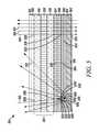
- FIG. 5illustrates the LC shutter of FIG. 3 with an additional narrowband dichroic polarizer in accordance with another embodiment
- FIG. 6illustrates the LC shutter of FIG. 3 with an additional narrowband dichroic polarizer having a different placement from that of FIG. 4 , in accordance with still another embodiment
- FIG. 7illustrates the display and a detailed view of the LC shutter of the electronic device of FIG. 2 , in accordance with an alternate embodiment
- FIG. 8is a flowchart illustrating one example of a method of making an LC shutter in accordance with one embodiment.
- FIG. 9is a flowchart illustrating one example of a method of making an LC shutter in accordance with an alternate embodiment.
- an electronic deviceincludes a display and an LC shutter. At least a portion of the LC shutter is operatively positioned over the display.
- the LC shutterprovides switching between a diffusive state and a transparent state with high image integrity, and with high transmission in the transparent state.
- the diffusive statecan be controlled to be a diffusive white state or a diffusive colored state, such as through the selective placement of a narrowband dichroic polarizer or narrowband reflective polarizer within the LC shutter to introduce color.
- the electronic devicefurther includes control logic operatively coupled to the LC shutter and operative to provide control signals to the LC shutter to effect the transparent state.
- the LC shutter ( 204 )includes a first dichroic polarizer ( 300 ), such as a broadband dichroic polarizer, an LC cell ( 304 ), and a diffusive reflective polarizer ( 307 ).
- the LC cell ( 304 )is interposed between the first dichroic polarizer ( 300 ) and the diffusive reflective polarizer ( 307 ).
- the LC shutterincludes a first dichroic polarizer, such as a broadband dichroic polarizer, a specular reflective polarizer, such as a broadband specular reflective polarizer, an LC cell, and an in-plane anisotropic diffuser, such as an in-plane anisotropic diffuser film.
- a first dichroic polarizersuch as a broadband dichroic polarizer
- a specular reflective polarizersuch as a broadband specular reflective polarizer
- an LC celland an in-plane anisotropic diffuser, such as an in-plane anisotropic diffuser film.
- an in-plane anisotropic diffuserhereinafter means a diffuser in which at least 50 percent of light polarized in one direction is selectively diffusively transmitted (the remainder of such light being selectively diffusively reflected), while essentially all of the light polarized in the other direction is specularly transmitted.
- the in-plane anisotropic diffusermay selectively diffusively transmit 60 percent of the light polarized in one direction, or any suitable percentage of such light.
- the LC cellis interposed between the first dichroic polarizer and the specular reflective polarizer.
- the in-plane anisotropic diffuseris interposed between the LC cell and the specular reflective polarizer.
- the LC shutterfurther includes a second dichroic polarizer that is a narrowband dichroic polarizer.
- the second dichroic polarizeris interposed between the in-plane anisotropic diffuser and the specular reflective polarizer.
- the second dichroic polarizeris interposed between the LC cell and the in-plane anisotropic diffuser.
- the LC shutterstill further includes an additional dichroic polarizer, such as a broadband dichroic polarizer.
- an additional dichroic polarizersuch as a broadband dichroic polarizer.
- the LC cell, the in-plane anisotropic diffuser, the specular reflective polarizer, and, if present, the second dichroic polarizer,are interposed between the first dichroic polarizer and the additional dichroic polarizer.
- a diffusive reflective polarizercan be used in place of a combination of in-plane anisotropic diffuser and broadband specular reflective polarizer.
- the LC cellis placed between the first dichroic polarizer and the diffusive reflective polarizer.
- a diffusive reflective polarizerhereinafter means a polarizer in which essentially all of the light polarized in one direction is selectively diffusively reflected while essentially all of the light polarized in the other direction is selectively specularly transmitted.
- a second dichroic polarizerthat is a narrowband dichroic polarizer is interposed between the LC cell and the diffusive reflective polarizer.
- an LC shutter and a device including an LC shutterprovide appealing visual effects such as switching between a transparent state and a diffusive state to change, for example, the color or visual appearance of, in one example, an exterior surface of a handheld device or other suitable device.
- the LC shuttercan switch between bright diffusive colors or bright diffusive white and a highly transparent state.
- the devicecan appear to be morphing from one color to a transparent state to provide different looks thereby enhancing user appeal.
- FIG. 1illustrates an example of a prior art electronic device 10 having a display 12 and an LC shutter 14 capable of switching between a transparent state, as illustrated by the light depicted on the right portion of FIG. 1 , and a specular state, as illustrated by the light depicted on the left portion of FIG. 1 .
- the electronic devicemay further include an electroluminescent or reflecting element 16 , such as a keypad portion.
- the LC shutter 14includes a first dichroic polarizer 18 , a second dichroic polarizer 20 , an LC cell 22 , and a specular reflective polarizer 24 .
- the first dichroic polarizer 18includes a first axis 26 and a second axis 28 .
- the second dichroic polarizer 20includes a first axis 30 and a second axis 32 .
- the specular reflective polarizer 24includes a first axis 34 and a second axis 36 .
- the LC cell 22includes a first substrate 38 , a second substrate 40 , and liquid crystal material 42 .
- the LC cell 22is interposed between the first dichroic polarizer 18 and the specular reflective polarizer 24 .
- the LC cell 22 and specular reflective polarizer 24are interposed between the first dichroic polarizer 18 and the second dichroic polarizer 20 .
- the first dichroic polarizer 18is generally a broadband dichroic polarizer.
- a broadband polarizeris responsive to a continuous, wide range of electromagnetic frequencies, typically including all frequencies or colors within the range of visible light.
- a dichroic polarizeris substantially transparent to light polarized along a first axis of the dichroic polarizer, also known as a transmission axis or a transmissive axis, and substantially absorbs light polarized along a second axis of the dichroic polarizer that is different from the first axis. Accordingly, the first dichroic polarizer 18 transmits first polarized light 46 to the LC cell 22 that is substantially polarized along the first axis 26 of the first dichroic polarizer 18 and that is the same color as the ambient light 44 .
- a voltagemay be applied to the LC cell 22 . If a voltage is applied to the LC cell 22 , the liquid crystal material 42 , and hence the LC cell 22 , will pass the first polarized light 46 without rotating its polarization, thereby producing post-LC light 48 . However, if a voltage is not applied to the LC cell 22 , the liquid crystal material 42 , and hence the LC cell 22 , will pass the first polarized light 46 with a rotation, or “twist,” of its polarization to produce the post-LC light 48 .
- post-LC light 48 that exits the LC cell 22is substantially polarized in the same direction as the first axis 26 of the first dichroic polarizer 18 .
- the post-LC light 48is substantially polarized in a different direction because of the polarization rotation effect of the LC cell 22 .
- the ambient light 44is then transmitted to the specular reflective polarizer 24 .
- the specular reflective polarizer 24is typically a broadband specular reflective polarizer.
- a broadband reflective polarizerlike a broadband dichroic polarizer, is responsive to a continuous, wide range of electromagnetic frequencies typically including all frequencies or colors within the range of visible light and is substantially transparent to light polarized along a first axis.
- a broadband reflective polarizersubstantially reflects, instead of absorbs, light polarized along a second axis that is different from its first axis.
- a broadband specular reflective polarizersubstantially specularly reflects this light.
- the reflection of this lightproduces a metallic or mirror-like appearance, as opposed to a situation in which light is dispersed upon reflection, also known as a diffusive reflection, such as the case of a shadow produced by the reflection of a person's face from a piece of white paper.
- the specular reflective polarizer 24transmits post-specular reflective polarizer light 50 to the second dichroic polarizer 20 that is substantially polarized along the first axis 30 of the specular reflective polarizer 24 , and that is the same color as the post-LC light 48 .
- the specular reflective polarizer 24specularly reflects those components.
- the second dichroic polarizer 20is generally a broadband dichroic polarizer.
- the second dichroic polarizer 20is used to enhance the polarization effect of the LC shutter 14 during operation in the transparent state in view of the non-ideal responses of the above components of the LC shutter 14 .
- the extent to which ambient light 44 may be transmitted through the LC shutter 14will depend both upon the orientation of the first axes 26 , 30 , and 34 and second axes 28 , 32 , and 36 of each of the first dichroic polarizer 18 , second dichroic polarizer 20 , and specular reflective polarizer 24 , respectively, and upon whether a voltage is applied to the LC cell 22 and if not, what angle of polarization rotation is introduced by the LC cell 22 .
- the prior art system of FIG. 1switches between a transparent state and a specular state by way of switching between the presence or absence of applied voltage to the LC cell 22 .
- any components of ambient light 44 which are polarized along the second axes 28 , 32 , and 36 of the polarizers 18 , 20 , and 24 of the LC shutter 14are substantially transmitted through the LC shutter 14 , as described above.
- any components of ambient light 44 which are polarized along the second axis 28 of the first dichroic polarizer 18are substantially absorbed, but any components of ambient light 44 which are polarized along the first axis 26 of the first dichroic polarizer 18 are substantially transmitted through the first dichroic polarizer 18 to produce an output of first polarized light 46 .
- the first polarized light 46then has its polarization rotated 90° by the LC cell 22 and outputted from the LC cell 22 as post-LC light 48 .
- the post-LC light 48is substantially polarized along the second axis 36 of the specular reflective polarizer 24 . Accordingly, the post-LC light 48 is substantially specularly reflected by the specular reflective polarizer 24 , and not transmitted to the display 12 .
- any components of light coming from the display 12 which are polarized along the first axis 26 of the second dichroic polarizer 20are substantially transmitted therethrough, while any components of light coming from the display 12 which are polarized along the second axis 28 of the second dichroic polarizer 20 are substantially absorbed. Because the components polarized along the first axis 26 of the second dichroic polarizer 20 have their polarization rotated 90° when they reach the LC cell 22 , they are then substantially absorbed by the first dichroic polarizer 18 , and thus substantially no light from the display 12 is transmitted through the LC shutter 14 .
- the prior art systemcan achieve switching between a transparent state and a specular reflective state, but is unable to achieve switching between a transparent state and a diffusive state.
- FIG. 2is a block diagram of an electronic device 200 , illustrating a display 202 , an LC shutter 204 , and control logic 206 in accordance with one embodiment of the present invention.
- the electronic device 200may further include an electroluminescent or reflecting element 208 .
- the electronic device 200may be, for example, a cellular telephone, personal digital assistant (“PDA”), laptop computer, desktop computer, television, printer, or any suitable handheld, portable, or fixed electronic device.
- the display 202may be, for example, a cathode ray tube display, liquid crystal display (“LCD”), thin film transistor liquid crystal display, or any suitable device for displaying content to a user.
- LCDliquid crystal display
- FIG. 2is a block diagram of an electronic device 200 , illustrating a display 202 , an LC shutter 204 , and control logic 206 in accordance with one embodiment of the present invention.
- the electronic device 200may further include an electroluminescent or reflecting element 208 .
- the electronic device 200may be,
- the control logic 206may be, for example, a digital signal processor, microcontroller, central processing unit, baseband processor, co-processor, or any suitable processing device. In addition, it may be discrete logic, or any suitable combination of hardware, software or firmware or any suitable structure.
- the electroluminescent or reflecting element 208may be, for example, a keypad portion of the electronic device 200 that is operative to emit light or reflect light. For convenience, the electroluminescent or reflecting element 208 will be referred to hereinafter as a keypad portion, it being understood that the electroluminescent or reflecting element may be any suitable light source or reflecting source as described above.
- At least a portion of the LC shutter 204is operatively positioned over the display 202 .
- the keypad portion 208is included, at least a portion of the LC shutter 204 is further operatively positioned over the keypad portion 208 .
- the control logic 206is operatively coupled to the LC shutter 204 and operative to cause the LC shutter 204 to switch between a transparent state, as illustrated by the light depicted on the right portion of the figure, and a diffusive state, as illustrated by the light depicted on the left portion of the figure.
- a transparent stateis to be interpreted as a state in which the LC shutter 204 is substantially transparent with respect to incoming light, taking into account polarization imperfections of the LC shutter 204 as known in the art.
- a diffusive stateis to be interpreted as a state in which the LC shutter 204 is substantially diffusive with respect to incoming light, taking into account the polarization imperfections of the LC shutter 204 .
- ambient light 210is substantially transmitted through the LC shutter 204 .
- the ambient light 210may be, for example, natural light, artificial light, or any suitable light in the environment of the LC shutter 204 .
- light from the display 202 and, if the keypad portion 208 is present, light from the keypad portion 208is substantially transmitted through the LC shutter 204 .
- ambient light 210is diffusely reflected by the LC shutter 204 and in some embodiments is also colored by the LC shutter 204 , as described in detail below. Additionally, any light from the display 202 and the keypad portion 208 is substantially not transmitted through the LC shutter 204 .
- control logic 206is operative to provide control signals 212 , in the form of applied voltages, to the LC shutter 204 to effect the transparent state.
- control logic 206does not provide any control signals 212 to the LC shutter 204 , the LC shutter 204 operates in the diffusive state.
- the electronic device 200 of FIG. 2is shown with a detailed view of the LC shutter 204 .
- the electronic device 200may further include a keypad portion 208 and is shown as such in FIG. 3 .
- the electronic device 200still further includes one or more various subsystems, such as a radio-telephone subsystem operatively coupled to the display 202 , a video playback subsystem, an audio playback subsystem, or any suitable subsystem.
- the LC shutter 204includes a first dichroic polarizer 300 , a specular reflective polarizer 302 , an LC cell 304 , and a in-plane anisotropic diffuser 306 .
- the LC shutter 204includes one or both of a second dichroic polarizer (not shown in FIG. 3 ) and an additional dichroic polarizer 308 , as discussed in detail below.
- the first dichroic polarizer 300includes a first (i.e., transmissive) axis 310 and a second (i.e., absorptive) axis 312 .
- the first dichroic polarizer 300may be made from, for example, an iodine complex, dichroic dyes, or any other suitable material.
- a dichroic polarizeris substantially transparent to light polarized along a first axis and substantially absorbs light polarized along a second axis that is different from the first axis.
- an axisrefers to any line in space of any orientation and is not limited to a line which defines, for example, a coordinate axis.
- the first dichroic polarizer 300is a broadband dichroic polarizer, such as that manufactured by Nitto Denko Corporation or Sumitomo Chemical Co., Ltd.
- the specular reflective polarizer 302includes a first (i.e., transmissive) axis 314 and a second (i.e., reflective) axis 316 .
- the specular reflective polarizer 302may be made from, for example, a polymer multi-layer material or any suitable material.
- the specular reflective polarizer 302may be the DBEF (Dual Brightness Enhancement Film) manufactured by 3M.
- the specular reflective polarizer 302is a broadband specular reflective polarizer.
- the LC cell 304is interposed between the first dichroic polarizer 300 and the specular reflective polarizer 302 and includes, for example, a first substrate 318 such as a top substrate, a second substrate 320 such as a bottom substrate, and liquid crystal material 322 interposed between the first substrate 318 and the second substrate 320 .
- the first substrate 318 and second substrate 320may be made from, for example, glass, polycarbonate, or cyclic polyolephine or any suitable polymer that is substantially transparent and of low birefringence.
- an applied voltage to the LC cell 304such as through control signals 212
- the liquid crystal material 322passes incident light without rotating its polarization.
- the liquid crystal material 322is operative to rotate the polarization of incident light while passing that incident light.
- the in-plane anisotropic diffuser 306is interposed between the LC cell 304 and the specular reflective polarizer 302 .
- the in-plane anisotropic diffuser 306includes a first axis 324 and a second axis 326 .
- the in-plane anisotropic diffuser 306may be, for example, an in-plane anisotropic diffuser film or any other suitable type of in-plane anisotropic diffuser.
- FIG. 4illustrates an exemplary embodiment of the in-plane anisotropic diffuser 306 as a stretched PDLC (Polymer-Dispersed Liquid Crystal) film.
- the in-plane anisotropic diffuser 306may also be made from any of several other constructions, such as a PNLC (Polymer Network Liquid Crystal) film on a rubbed polyimide surface or any other suitable construction.
- PNLCPolymer Network Liquid Crystal
- the in-plane anisotropic diffuser 306includes a matrix 400 and at least one domain 402 dispersed within the matrix 400 .
- the in-plane anisotropic diffuser 306is such that there is a refractive index match between the matrix 400 and the at least one domain 402 along a first axis 324 of the in-plane anisotropic diffuser 306 , and a refractive index mismatch between the matrix 400 and the at least one domain 402 along a second axis 326 of the in-plane anisotropic diffuser 306 which is different from the first axis 324 .
- first axis and the second axisare substantially in the plane of the in-plane anisotropic diffuser 306 .
- first axis 324 and the second axis 326are perpendicular to one another, but as recognized by one having ordinary skill in the art, the first axis 324 and second axis 326 may be at any suitable orientations.
- the matrix 400includes a polymer, such as Polymethylemethacrylate, and the at least one domain 402 includes a liquid crystal material.
- the refractive index mismatch between the matrix 400 and the at least one domain 402 along the second axis 326is greater than 0.05.
- the stretchaligns the at least one domain 402 so as to achieve the refractive index mismatch.
- the rubbed polyimidealigns the at least one domain 402 so as to achieve the refractive index mismatch.
- the first dichroic polarizer 300outputs first polarized light 328
- the LC cell 304outputs post-LC light 330
- the in-plane anisotropic diffuseroutputs post-in-plane anisotropic diffuser light 332
- the specular reflective polarizeroutputs post-specular reflective polarizer light 334 .
- the first dichroic polarizer 300 , specular reflective polarizer 302 , and LC cell 304operate in the same manner as that described above with respect to FIG. 1 .
- the in-plane anisotropic diffuser 306is transparent to incoming light polarized along the first axis 324 , and scattering to, i.e., introduces a diffusive appearance to, incoming light polarized along the second axis 326 .
- transparent to and scattering toare to be interpreted as being substantially transparent to and substantially scattering to incoming light, respectively, taking into account imperfections of the in-plane anisotropic diffuser 306 .
- the first axes 310 , 314 , and 324 and second axes 312 , 316 , and 326 of each of the first dichroic polarizer 300 , specular reflective polarizer 302 , and in-plane anisotropic diffuser 306 , respectively,are oriented as follows: the first axes 310 , 314 , and 324 are all aligned with one another, the second axes 312 , 316 , and 326 are all aligned with one another, and each of the first axes 310 , 314 , and 324 are substantially perpendicular to each of the second axes 312 , 316 , and 326 .
- the LC cell 304rotates the polarization of light incident upon it by 90°, but it is to be understood that any suitable angle of rotation is contemplated.
- the LC shutter 204is polarization-sensitive and switches effectively between a transparent state and a diffusive state with high image integrity, and with high transmission in the transparent state, by way of switching between the presence or absence of applied voltage to the LC cell 304 .
- any components of ambient light 210which are polarized along the second axes 312 and 316 of the polarizers 300 and 302 and the second axis 326 of the in-plane anisotropic diffuser 306 of the LC shutter 204 are substantially absorbed.
- any components of ambient light 210 which are polarized along the first axes 310 and 314 of the polarizers 300 and 302 and the first axis 324 of the in-plane anisotropic diffuser 306 of the LC shutter 204are substantially transmitted through the LC shutter 204 .
- light coming from the display 202 and, if the keypad portion 208 is present, light coming from the keypad portion 208may be transmitted through the LC shutter 204 in the opposite order of transmission as that described above because each of the components of the LC shutter 204 has the same response to light incident from either direction.
- any components of ambient light 210 which are polarized along the second axis 312 of the first dichroic polarizer 300are substantially absorbed, but any components of ambient light 210 which are polarized along the first axis 310 of the first dichroic polarizer 300 are substantially transmitted through the first dichroic polarizer 300 as first polarized light 328 , and then have their polarization rotated by the LC cell 304 , producing post-LC light 330 .
- the post-LC light 330is substantially polarized along the second axis 326 of the in-plane anisotropic diffuser 306 . Therefore, in accordance with the discussion above regarding the response of the in-plane anisotropic diffuser 306 to light incident along its second axis 326 , the in-plane anisotropic diffuser 306 partially scatters and reflects, and partially scatters and transmits, the post-LC light 330 .
- the components of post-LC light 330 that are partially scattered and transmitted by the in-plane anisotropic diffuser 306because they are polarized along the second axis 316 of the specular reflective polarizer 302 , are substantially reflected by the specular reflective polarizer 302 .
- the specular reflection of such componentsappears diffuse because the incident components are diffuse (as a result of being scattered by the in-plane anisotropic diffuser 306 ) before they reach the specular reflective polarizer 302 .
- ambient light 210is not transmitted to the display 202 , but is instead diffusively reflected by the LC shutter 204 .
- any components of light coming from the display 202 which are polarized along the first axis 314 of the specular reflective polarizer 302are substantially transmitted therethrough, while any components of light coming from the display 202 which are polarized along the second axis 316 of the specular reflective polarizer 302 are substantially reflected therefrom.
- the components polarized along the first axis 314 of the specular reflective polarizer 302have their polarization rotated 90° when they reach the LC cell 304 , they are then substantially absorbed by the first dichroic polarizer 300 , and thus not transmitted through the LC shutter 204 .
- the LC shutter 204 of the present inventionis therefore operative to achieve switching between a transparent state and a diffusive state. Because of the polarization effect of the LC shutter 204 that is introduced by the first dichroic polarizer 300 and the specular reflective polarizer 302 , the LC shutter 204 of the present invention is able to achieve this switching with high image integrity and with high transmission in the transparent state.
- a second dichroic polarizer 500may be interposed between the in-plane anisotropic diffuser 306 and the specular reflective polarizer 302 .
- the second dichroic polarizer 500includes a first (i.e., transmissive) axis 502 and a second (i.e., absorptive) axis 504 .
- the second dichroic polarizer 500is a narrowband dichroic polarizer, with its first axis 502 aligned with the first axes 310 and 314 of the polarizers 300 and 302 and the first axis 324 of the in-plane anisotropic diffuser 306 .
- the second axis 504 of the second dichroic polarizer 500is aligned with the second axis 312 and 316 of the polarizers 300 and 302 and the second axis 326 of the in-plane anisotropic diffuser 306 .
- a narrowband dichroic polarizerpolarizes light in a limited range in the visible wavelength of light.
- the second dichroic polarizer 500may be, for example, a narrowband dichroic polarizer manufactured by Polatechno Co., Ltd. or any suitable narrowband dichroic polarizer.
- post-in-plane anisotropic diffuser light 332is substantially polarized along the second axes 312 and 316 of the polarizers 300 and 302 and the second axis 326 of the in-plane anisotropic diffuser 306 and consequently, in a preferred embodiment, is also polarized along the absorption axis of the second dichroic polarizer 500 . Therefore, post-in-plane anisotropic diffuser light 332 is colored by the second dichroic polarizer 500 , producing colored light 506 which is then incident upon the specular reflective polarizer 302 .
- Colored light 506because it is polarized along the second axis 316 of the specular reflective polarizer 302 , is then reflected by the specular reflective polarizer 302 , producing a diffusive colored state of the LC shutter 204 .
- yet another embodiment of the present inventionincludes the second dichroic polarizer 500 interposed between the LC cell 304 and the in-plane anisotropic diffuser 306 .
- post-LC light 330is substantially polarized along the second axes 312 and 316 of the polarizers 300 and 302 and the second axis 326 of the in-plane anisotropic diffuser 306 , and consequently, in a preferred embodiment, is also substantially polarized along the second axis 504 of the second dichroic polarizer 500 .
- the post-LC light 330is then colored by the second dichroic polarizer 500 , producing colored light 506 which is then incident upon the in-plane anisotropic diffuser 306 .
- the in-plane anisotropic diffuser 306then partially scatters and reflects, and partially scatters and transmits, the colored light 506 .
- Post-in-plane anisotropic diffuser light 332i.e., light that is scattered and transmitted by the in-plane anisotropic diffuser 306 and incident upon the specular reflective polarizer 302 , is then substantially reflected by the specular reflective polarizer 302 .
- the configuration of FIG. 6provides a greater degree of coloring when the LC shutter 204 operates in the diffusive state (i.e., with no applied voltage) because all post-LC light 330 that is incident upon the in-plane anisotropic diffuser 306 is colored.
- the configuration of FIG. 5only the components of post-LC light 330 that are partially scattered and transmitted by the in-plane anisotropic diffuser 306 reach the second dichroic polarizer 500 .
- the present inventionfurther contemplates an additional embodiment in which the LC shutter 204 provides coloring without the need for the second dichroic polarizer 500 .
- the specular reflective polarizer 302is a narrowband specular reflective polarizer. Accordingly, the specular reflective polarizer 302 provides the coloring that is provided by the second dichroic polarizer 500 in, for example, FIG. 5 .
- the LC shutter 204 of the present inventionmay further include an additional dichroic polarizer 308 .
- the additional dichroic polarizer 308is a broadband dichroic polarizer, and the LC cell 304 , in-plane anisotropic diffuser 306 , specular reflective polarizer 302 , and, if present, second dichroic polarizer 500 , are interposed between the first dichroic polarizer 300 and the additional dichroic polarizer 308 .
- the additional dichroic polarizer 308has a first axis 336 and a second axis 338 , which in a preferred embodiment are aligned, respectively, with the first axes 310 and 314 and the second axes 312 and 316 of the polarizers 300 and 302 , and the first axis 324 and the second axis 326 of the in-plane anisotropic diffuser 306 of the LC shutter 204 .
- the additional dichroic polarizer 308enhances the polarization effect of the LC shutter 204 and is beneficial in view of the non-ideal responses of each of the above components of the LC shutter 204 .
- the present inventionalso contemplates an alternate embodiment of the LC shutter 204 from those described with respect to FIGS. 3-6 .
- the LC shutter 204includes the first dichroic polarizer 300 , the LC cell 304 , and a diffusive reflective polarizer 307 , but does not include the specular reflective polarizer 302 .
- the LC shutter 204may further include the second dichroic polarizer 500 and/or the additional dichroic polarizer 308 .
- the first dichroic polarizeris a broadband dichroic polarizer
- the second dichroic polarizer, if presentis a narrowband dichroic polarizer
- the additional dichroic polarizer, if presentis a broadband dichroic polarizer
- the diffusive reflective polarizer 307has higher reflectivity than the in-plane anisotropic diffuser 306 used in the embodiments shown and described with respect to FIGS. 3 , 5 and 6 .
- the diffusive reflective polarizermay be, for example, the DRPF (Diffuse Reflective Polarizing Film) manufactured by 3M.
- the DRPFis made from two immiscible polymers.
- the textureis a continuous domain made from a first polymer of a first kind, such as polyethylene naphthalate, and a second polymer of a second kind, such as polymethylmethacrylate.
- the refractive index mismatch between the first polymer and the second polymer along the second axis 326be greater than 0.05.
- the diffusive reflective polarizer 307includes a first axis 325 and a second axis 327 . Unlike the in-plane anisotropic diffuser 306 , the diffusive reflective polarizer 307 is backward scattering to, i.e., causes a diffusive reflection of, essentially all light polarized along the second axis 327 , while transmitting essentially all light polarized along the first axis 325 .
- the diffusive reflective polarizer 307scatters and reflects, as opposed to scatters and transmits, a greater amount of light incident upon it, thus allowing the LC shutter 204 to operate without the specular reflective polarizer 302 placed after the diffusive reflective polarizer 307 .
- FIG. 8is a flowchart illustrating one example of a method of making an LC shutter, such as the LC shutter 204 .
- the methodincludes attaching a first side of an LC cell, such as the LC cell 304 , to a first side of a first dichroic polarizer, such as the first dichroic polarizer 300 .
- the methodfurther includes attaching a second side of the LC cell 304 to a first side of an in-plane anisotropic diffuser, such as the in-plane anisotropic diffuser 306 described above with respect to, for example, the embodiments of FIGS. 3 , 5 and 6 .
- an in-plane anisotropic diffusersuch as the in-plane anisotropic diffuser 306 described above with respect to, for example, the embodiments of FIGS. 3 , 5 and 6 .
- the methodstill further includes attaching a second side of the in-plane anisotropic diffuser 306 to a first side of a specular reflective polarizer, such as the specular reflective polarizer 302 .
- the specular reflective polarizer 302may be a broadband specular reflective polarizer or, in one embodiment, may be a narrowband specular reflective polarizer for coloring light and enabling a diffusive colored state, as discussed above with respect to, for example, FIG. 3 .
- the methodmay still further include attaching the second side of the specular reflective polarizer 302 to a first side of an additional dichroic polarizer, such as the additional dichroic polarizer 308 , as shown in block 806 .
- the polarization effect of the LC shutter 204may therefore be increased in view of the non-ideal responses of each of the above components of the LC shutter 204 .
- block 802includes block 808 ; namely, placing a second dichroic polarizer, such as the second dichroic polarizer 500 , between the LC cell 304 and the in-plane anisotropic diffuser 306 for coloring light and enabling a diffusive colored state, as discussed above with respect to, for example, FIG. 6 .
- a second dichroic polarizersuch as the second dichroic polarizer 500
- block 804includes block 810 ; namely, placing a second dichroic polarizer, such as the second dichroic polarizer 500 , between the in-plane anisotropic diffuser 306 and the specular reflective polarizer 302 for coloring light and enabling a diffusive colored state as discussed above with respect to, for example, FIG. 5 .
- a second dichroic polarizersuch as the second dichroic polarizer 500
- the methodmay be performed using any suitable manner of attachment including, for example, the use of PSAs (pressure sensitive adhesives), index-matching fluid, or any suitable chemical, mechanical, or other manner of optically coupling two elements together with substantially no air between them.
- the attachmentis generally performed by one or more machines, but as recognized by one having ordinary skill in the art, may also be performed by a human or by a combination of a human and one or more machines.
- the LC shutterprovides switching between a transparent state and a diffusive state with high image integrity and high transmission in the transparent state. It will be appreciated that the above method need not be performed in the order described. Rather, the present disclosure contemplates any sensible variation of arrangement. By way of example, the method could be performed in reverse order, starting from block 806 , if block 806 is included, and otherwise starting from block 804 .
- FIG. 9illustrates another method in accordance with the alternate embodiment of the LC shutter 204 described with respect to FIG. 7 .
- the methodincludes attaching a first side of an LC cell, such as the LC cell 304 , to a first side of a first dichroic polarizer, such as the first dichroic polarizer 300 .
- the methodincludes attaching a second side of the LC cell 304 to a first side of a second dichroic polarizer, such as the second dichroic polarizer 500 , for coloring light and enabling a diffusive colored state as described above with respect to, for example, FIG. 7 .
- a second dichroic polarizersuch as the second dichroic polarizer 500
- the methodstill further includes attaching a second side of the second dichroic polarizer 500 to a first side of a diffusive reflective polarizer, such as the diffusive reflective polarizer 307 , as described above with respect to, for example, FIG. 7 .
- a diffusive reflective polarizersuch as the diffusive reflective polarizer 307
- the methodmay still further include block 906 ; namely, attaching the second side of the diffusive reflective polarizer 307 to a first side of an additional dichroic polarizer, such as the additional dichroic polarizer 708 .
- the polarization effect of the LC shutter 204may therefore be increased in view of the non-ideal responses of each of the above components of the LC shutter 204 .
- the methodmay be performed using any suitable manner of attachment as described above with respect to FIG. 8 . Similarly, the method may be performed in any sensible order, as also described above with respect to FIG. 8 .
- an LC shutter and a device including an LC shutterprovide appealing visual effects such as switching between a transparent state and a diffusive state to change, for example, the color or visual appearance of, in one example, an exterior surface of a handheld device or other suitable device.
- the LC shuttercan switch between bright diffusive colors or bright diffusive white and a highly transparent state.
- the devicecan appear to be morphing from one color to a transparent state to provide different looks thereby enhancing user appeal.
Landscapes
- Physics & Mathematics (AREA)
- Nonlinear Science (AREA)
- Mathematical Physics (AREA)
- Chemical & Material Sciences (AREA)
- Crystallography & Structural Chemistry (AREA)
- General Physics & Mathematics (AREA)
- Optics & Photonics (AREA)
- Polarising Elements (AREA)
- Liquid Crystal (AREA)
Abstract
Description
Claims (15)
Priority Applications (2)
| Application Number | Priority Date | Filing Date | Title |
|---|---|---|---|
| US12/028,092US7864270B2 (en) | 2008-02-08 | 2008-02-08 | Electronic device and LC shutter with diffusive reflective polarizer |
| PCT/US2009/032940WO2009100055A2 (en) | 2008-02-08 | 2009-02-03 | Electronic device and lc shutter with diffusive reflective polarizer |
Applications Claiming Priority (1)
| Application Number | Priority Date | Filing Date | Title |
|---|---|---|---|
| US12/028,092US7864270B2 (en) | 2008-02-08 | 2008-02-08 | Electronic device and LC shutter with diffusive reflective polarizer |
Publications (2)
| Publication Number | Publication Date |
|---|---|
| US20090201447A1 US20090201447A1 (en) | 2009-08-13 |
| US7864270B2true US7864270B2 (en) | 2011-01-04 |
Family
ID=40938581
Family Applications (1)
| Application Number | Title | Priority Date | Filing Date |
|---|---|---|---|
| US12/028,092Expired - Fee RelatedUS7864270B2 (en) | 2008-02-08 | 2008-02-08 | Electronic device and LC shutter with diffusive reflective polarizer |
Country Status (2)
| Country | Link |
|---|---|
| US (1) | US7864270B2 (en) |
| WO (1) | WO2009100055A2 (en) |
Cited By (3)
| Publication number | Priority date | Publication date | Assignee | Title |
|---|---|---|---|---|
| US20190278009A1 (en)* | 2015-05-29 | 2019-09-12 | 3M Innovative Properties Company | Optical constructions |
| US10520782B2 (en) | 2017-02-02 | 2019-12-31 | James David Busch | Display devices, systems and methods capable of single-sided, dual-sided, and transparent mixed reality applications |
| US10585307B2 (en) | 2016-03-30 | 2020-03-10 | Motorola Mobility Llc | Display construct with integrated switchable mirror and corresponding systems and methods |
Families Citing this family (5)
| Publication number | Priority date | Publication date | Assignee | Title |
|---|---|---|---|---|
| US8059232B2 (en)* | 2008-02-08 | 2011-11-15 | Motorola Mobility, Inc. | Electronic device and LC shutter for polarization-sensitive switching between transparent and diffusive states |
| US20090219253A1 (en)* | 2008-02-29 | 2009-09-03 | Microsoft Corporation | Interactive Surface Computer with Switchable Diffuser |
| US8157399B2 (en)* | 2008-10-03 | 2012-04-17 | General Electric Company | Control unit for an appliance |
| CN205427321U (en)* | 2015-04-04 | 2016-08-03 | 孔晓辉 | Head raising displayer |
| JP6767717B2 (en)* | 2016-07-12 | 2020-10-14 | パナソニックIpマネジメント株式会社 | Lighting equipment |
Citations (104)
| Publication number | Priority date | Publication date | Assignee | Title |
|---|---|---|---|---|
| US3915548A (en) | 1973-04-30 | 1975-10-28 | Hughes Aircraft Co | Holographic lens and liquid crystal image source for head-up display |
| US4500173A (en) | 1983-05-02 | 1985-02-19 | Timex Corporation | Electroluminescent lamp for liquid crystal display |
| US4728936A (en) | 1986-04-11 | 1988-03-01 | Adt, Inc. | Control and display system |
| US5121234A (en) | 1990-10-29 | 1992-06-09 | Honeywell Incorporated | Dichroic liquid crystal display with integral electroluminescent backlighting |
| US5225818A (en) | 1990-11-26 | 1993-07-06 | Data Entry Products, Incorporated | Data entry control panel |
| US5231381A (en) | 1989-10-02 | 1993-07-27 | U.S. Philips Corp. | Data processing system with a touch screen and a digitizing tablet, both integrated in an input device |
| JPH0629275A (en) | 1991-05-30 | 1994-02-04 | Komatsu Ltd | High temperature heating device for chemicals |
| US5376948A (en) | 1992-03-25 | 1994-12-27 | Visage, Inc. | Method of and apparatus for touch-input computer and related display employing touch force location external to the display |
| JPH0863271A (en) | 1994-08-19 | 1996-03-08 | Fujitsu General Ltd | keyboard |
| US5796454A (en) | 1996-12-04 | 1998-08-18 | Advanced Display Systems, Inc. | Cholesteric liquid crystal display employing circular polarizer and methods of operation and manufacture therefor |
| US5818615A (en) | 1993-12-02 | 1998-10-06 | Ois Optical Imaging Systems, Inc. | Liquid crystal display with patterned retardation films |
| US5881377A (en)* | 1996-08-29 | 1999-03-09 | Motorola, Inc. | Communication device and display blanking control method therefor |
| KR20000007200A (en) | 1998-07-01 | 2000-02-07 | 김영환 | Device for receiving clock from digital clock supplying device of radio subscriber network system |
| US6047196A (en) | 1995-11-24 | 2000-04-04 | Nokia Mobile Phones, Ltd. | Communication device with two modes of operation |
| JP2000098386A (en) | 1996-09-17 | 2000-04-07 | Seiko Epson Corp | Display device and electronic device using the same |
| US6058164A (en) | 1995-03-01 | 2000-05-02 | Fujitsu Limited | Mode-switchable telephone and mode setting and switching methods for the same |
| GB2348039A (en) | 1999-03-17 | 2000-09-20 | Motorola Inc | Display with aligned optical shutter and backlight cells |
| US6184955B1 (en) | 1997-01-17 | 2001-02-06 | Seiko Epson Corporation | Liquid crystal device and electronic apparatus using it |
| US6243080B1 (en) | 1998-07-14 | 2001-06-05 | Ericsson Inc. | Touch-sensitive panel with selector |
| US6271835B1 (en) | 1998-09-03 | 2001-08-07 | Nortel Networks Limited | Touch-screen input device |
| US6310609B1 (en) | 1997-04-17 | 2001-10-30 | Nokia Mobile Phones Limited | User interface with guide lights |
| US20010036013A1 (en) | 1999-04-22 | 2001-11-01 | 3M Innovative Properties Company | Optical devices using reflecting polarizing materials |
| US20010043297A1 (en) | 2000-01-21 | 2001-11-22 | Makoto Arai | Liquid crystal display device |
| US6327376B1 (en) | 1997-12-04 | 2001-12-04 | U.S. Philips Corporation | Electronic apparatus comprising fingerprint sensing devices |
| JP2002049461A (en) | 2000-08-04 | 2002-02-15 | Toppan Printing Co Ltd | Data input device |
| KR20020025646A (en) | 2001-04-24 | 2002-04-04 | 이경군 | Mushroomes a ventilation arrangement case |
| US6385139B1 (en) | 1999-01-13 | 2002-05-07 | Seiko Epson Corporation | Display device and electronic timepiece |
| US6470196B1 (en) | 1998-10-09 | 2002-10-22 | Nec Corporation | Portable communication apparatus |
| US20030025679A1 (en) | 1999-06-22 | 2003-02-06 | Cirque Corporation | System for disposing a proximity sensitive touchpad behind a mobile phone keypad |
| US20030054867A1 (en) | 2001-09-18 | 2003-03-20 | Homayoun Dowlat | Method and apparatus for alerting users of incoming calls and messages |
| US20030058223A1 (en) | 2001-09-21 | 2003-03-27 | Tracy James L. | Adaptable keypad and button mechanism therefor |
| JP2003101622A (en) | 2001-07-25 | 2003-04-04 | Hewlett Packard Co <Hp> | Communication device and method |
| US6574487B1 (en) | 2000-02-23 | 2003-06-03 | Motorola, Inc. | Communication device with a dual-sided liquid crystal display |
| US6574044B1 (en) | 1999-10-25 | 2003-06-03 | 3M Innovative Properties Company | Polarizer constructions and display devices exhibiting unique color effects |
| US6590705B1 (en) | 1996-02-29 | 2003-07-08 | 3M Innovative Properties Company | Optical film with co-continuous phases |
| US6646697B1 (en) | 1997-07-18 | 2003-11-11 | Citizen Watch Co., Ltd. | Liquid crystal display |
| US6662244B1 (en) | 1999-07-30 | 2003-12-09 | Sony Corporation | Information terminal |
| US6674504B1 (en)* | 2000-09-29 | 2004-01-06 | Kent Optronics, Inc. | Single layer multi-state ultra-fast cholesteric liquid crystal device and the fabrication methods thereof |
| US20040036821A1 (en) | 2002-08-22 | 2004-02-26 | Optiva, Inc. | Liquid crystal shutter |
| KR20040019677A (en) | 2002-08-29 | 2004-03-06 | 엘지전자 주식회사 | Apparatus for visualizing call on a telephone |
| US6704004B1 (en) | 2000-08-17 | 2004-03-09 | Nokia Mobile Phones Ltd. | Arrangement for integration of key illumination into keymat of portable electronic devices |
| US20040058718A1 (en) | 2002-09-19 | 2004-03-25 | Samsung Electronics Co., Ltd. | Method for giving notice of an incoming call in a mobile communication terminal |
| US20040100598A1 (en) | 2001-02-28 | 2004-05-27 | Masaya Adachi | Device capable of switching between image display status and a mirror status, and equipment provided therewith |
| US20040104826A1 (en) | 2002-10-31 | 2004-06-03 | Harald Philipp | Charge transfer capacitive position sensor |
| US6760157B1 (en) | 1996-02-29 | 2004-07-06 | 3M Innovative Properties Company | Brightness enhancement film |
| US6768481B2 (en) | 1997-07-25 | 2004-07-27 | Seiko Epson Corporation | Display device and electronic equipment employing the same |
| US20040218121A1 (en) | 2003-05-01 | 2004-11-04 | Zhiming Zhuang | Transflective color liquid crystal display with internal rear polarizer |
| US6813957B1 (en) | 1999-11-26 | 2004-11-09 | Karl-Otto Platz | Capacitive sensor on a transparent carrier |
| US6819316B2 (en) | 2001-04-17 | 2004-11-16 | 3M Innovative Properties Company | Flexible capacitive touch sensor |
| US6819380B2 (en) | 2002-10-11 | 2004-11-16 | Toppoly Optoelectronics Corp. | Double-sided LCD panel |
| US20040265602A1 (en) | 2001-10-05 | 2004-12-30 | Taichi Kobayashi | Transparent electroconductive film, method for manufacture thereof, and touch panel |
| US20050007339A1 (en) | 2003-06-12 | 2005-01-13 | Tadamitsu Sato | Inputting method and input device |
| US20050018106A1 (en) | 2003-02-18 | 2005-01-27 | Wang Ran-Hong Raymond | Liquid crystal display viewable under all lighting conditions |
| US20050020325A1 (en) | 2003-07-24 | 2005-01-27 | Motorola, Inc. | Multi-configuration portable electronic device and method for operating the same |
| US20050030048A1 (en) | 2003-08-05 | 2005-02-10 | Bolender Robert J. | Capacitive sensing device for use in a keypad assembly |
| US20050064913A1 (en) | 2003-08-18 | 2005-03-24 | Kim Byung-Jin | Incoming call alerting method and mobile communication terminal using the same |
| JP2005100186A (en) | 2003-09-25 | 2005-04-14 | Casio Comput Co Ltd | Software keyboard display device and display program |
| JP2005099470A (en) | 2003-09-25 | 2005-04-14 | Seiko Epson Corp | Liquid crystal device and electronic apparatus using the same |
| US20050088417A1 (en) | 2003-10-24 | 2005-04-28 | Mulligan Roger C. | Tactile touch-sensing system |
| US20050093767A1 (en) | 2003-10-30 | 2005-05-05 | Ritdisplay Corporation | Dual display device |
| US20050114825A1 (en) | 2003-11-24 | 2005-05-26 | International Business Machines Corporation | Laptop computer including a touch-sensitive display and method of driving the laptop computer |
| US20050134549A1 (en) | 2003-09-18 | 2005-06-23 | Citizen Watch Co.,Ltd. | Display Apparatus |
| US20050243069A1 (en) | 2004-04-30 | 2005-11-03 | Rudy Yorio | Display-input apparatus for a multi-configuration portable device |
| US6968744B1 (en) | 2004-10-18 | 2005-11-29 | Silverbrook Research Pty Ltd | Capacitative pressure sensor with close electrodes |
| US20050266891A1 (en) | 2003-03-14 | 2005-12-01 | Mullen Jeffrey D | Systems and methods for providing remote incoming call notification for cellular phones |
| US20060026535A1 (en) | 2004-07-30 | 2006-02-02 | Apple Computer Inc. | Mode-based graphical user interfaces for touch sensitive input devices |
| US20060038937A1 (en) | 2004-08-12 | 2006-02-23 | Seiko Epson Corporation | Electro-optical device, method of manufacturing the same, and electronic apparatus |
| US20060046792A1 (en) | 2004-08-31 | 2006-03-02 | Hassemer Brian J | Hinge apparatus and methods therefor |
| JP2006091486A (en) | 2004-09-24 | 2006-04-06 | Seiko Epson Corp | Electro-optical device and electronic apparatus |
| US20060146012A1 (en) | 2005-01-04 | 2006-07-06 | Arneson Theodore R | System and method for automatic display switching |
| US20060161871A1 (en) | 2004-07-30 | 2006-07-20 | Apple Computer, Inc. | Proximity detector in handheld device |
| US20060166702A1 (en) | 2005-01-24 | 2006-07-27 | Dietz Paul H | Cellular telephone with ear proximity display and lighting control |
| US20060181662A1 (en)* | 2003-03-07 | 2006-08-17 | Tadayuki Kameyama | High luminance polarizing plate, and liquid crystal panel and image display using same |
| US20060197753A1 (en) | 2005-03-04 | 2006-09-07 | Hotelling Steven P | Multi-functional hand-held device |
| US7106517B2 (en) | 2003-12-31 | 2006-09-12 | General Electric Company | Display optical films |
| JP2006243658A (en) | 2005-03-07 | 2006-09-14 | Sharp Corp | Panel substrate, method for manufacturing panel substrate, and method for manufacturing liquid crystal display panel |
| US7123945B2 (en) | 2001-11-26 | 2006-10-17 | Sony Corporation | Task display switching method, portable apparatus and portable communications apparatus |
| JP2006284757A (en) | 2005-03-31 | 2006-10-19 | Toppan Printing Co Ltd | Color filter and color liquid crystal display device |
| US7139114B2 (en) | 2004-12-20 | 2006-11-21 | Xerox Corporation | Bisymmetrical electric paper and a system therefor |
| US20060266640A1 (en) | 2005-05-26 | 2006-11-30 | Halsey Eugene L Iv | Capacitive touch screen and method of making same |
| KR100652767B1 (en) | 2005-11-11 | 2006-12-04 | 엘지전자 주식회사 | Screen display device and method of mobile communication terminal |
| KR20060134659A (en) | 2005-06-23 | 2006-12-28 | 엘지.필립스 엘시디 주식회사 | Display device and manufacturing method |
| US20060290871A1 (en) | 2005-06-22 | 2006-12-28 | Sanyo Epson Imaging Devices Corp. | Electro-optical device, method of manufacturing the same, and electronic apparatus |
| US20070030438A1 (en) | 2005-07-20 | 2007-02-08 | Min-Feng Chiang | Arrangement of photo spacer material |
| US7180672B2 (en) | 2002-05-20 | 2007-02-20 | General Electric Company | Optical substrate and method of making |
| US20070052689A1 (en) | 2005-09-02 | 2007-03-08 | Lg Electronics Inc. | Mobile communication terminal having content data scrolling capability and method for scrolling through content data |
| US20070075965A1 (en) | 2005-09-30 | 2007-04-05 | Brian Huppi | Automated response to and sensing of user activity in portable devices |
| WO2007081318A1 (en) | 2006-01-05 | 2007-07-19 | Tte Technology, Inc. | System and method for creating a mirror effect in a liquid crystal display |
| KR20070109603A (en) | 2006-05-12 | 2007-11-15 | 엘지.필립스 엘시디 주식회사 | Electrophoretic display device and manufacturing method |
| US20080169944A1 (en) | 2007-01-15 | 2008-07-17 | Cisco Technology, Inc. | Dynamic Number Keypad for Networked Phones |
| US20080207254A1 (en) | 2007-02-27 | 2008-08-28 | Pierce Paul M | Multimodal Adaptive User Interface for a Portable Electronic Device |
| US20080204428A1 (en) | 2007-02-27 | 2008-08-28 | Pierce Paul M | Multimodal Adaptive User Interface for an Electronic Device with Digital Branding Capabilities |
| US20080204418A1 (en) | 2007-02-27 | 2008-08-28 | Adam Cybart | Adaptable User Interface and Mechanism for a Portable Electronic Device |
| US20080204463A1 (en) | 2007-02-27 | 2008-08-28 | Adam Cybart | Adaptable User Interface and Mechanism for a Title Portable Electronic Device |
| US20080211734A1 (en) | 2005-06-14 | 2008-09-04 | Koninklijke Philips Electronics, N.V. | Combined Single/Multiple View-Display |
| US20080266500A1 (en)* | 2006-09-06 | 2008-10-30 | Fujifilm Corporation | Liquid crystal display device |
| US20080266244A1 (en) | 2007-04-30 | 2008-10-30 | Xiaoping Bai | Dual Sided Electrophoretic Display |
| US20080291169A1 (en) | 2007-05-21 | 2008-11-27 | Brenner David S | Multimodal Adaptive User Interface for a Portable Electronic Device |
| US20080309589A1 (en) | 2007-06-13 | 2008-12-18 | Morales Joseph M | Segmented Electroluminescent Device for Morphing User Interface |
| US20080316397A1 (en) | 2007-06-22 | 2008-12-25 | Polak Robert D | Colored Morphing Apparatus for an Electronic Device |
| US20090042619A1 (en) | 2007-08-10 | 2009-02-12 | Pierce Paul M | Electronic Device with Morphing User Interface |
| US20090046072A1 (en) | 2007-08-13 | 2009-02-19 | Emig David M | Electrically Non-interfering Printing for Electronic Devices Having Capacitive Touch Sensors |
| US20090161059A1 (en) | 2007-12-19 | 2009-06-25 | Emig David M | Field Effect Mode Electro-Optical Device Having a Quasi-Random Photospacer Arrangement |
| US20090201446A1 (en) | 2008-02-08 | 2009-08-13 | Motorola, Inc. | Electronic device and lc shutter for polarization-sensitive switching between transparent and diffusive states |
- 2008
- 2008-02-08USUS12/028,092patent/US7864270B2/ennot_activeExpired - Fee Related
- 2009
- 2009-02-03WOPCT/US2009/032940patent/WO2009100055A2/enactiveApplication Filing
Patent Citations (111)
| Publication number | Priority date | Publication date | Assignee | Title |
|---|---|---|---|---|
| US3915548A (en) | 1973-04-30 | 1975-10-28 | Hughes Aircraft Co | Holographic lens and liquid crystal image source for head-up display |
| US4500173A (en) | 1983-05-02 | 1985-02-19 | Timex Corporation | Electroluminescent lamp for liquid crystal display |
| US4728936A (en) | 1986-04-11 | 1988-03-01 | Adt, Inc. | Control and display system |
| US5231381A (en) | 1989-10-02 | 1993-07-27 | U.S. Philips Corp. | Data processing system with a touch screen and a digitizing tablet, both integrated in an input device |
| US5121234A (en) | 1990-10-29 | 1992-06-09 | Honeywell Incorporated | Dichroic liquid crystal display with integral electroluminescent backlighting |
| US5225818A (en) | 1990-11-26 | 1993-07-06 | Data Entry Products, Incorporated | Data entry control panel |
| JPH0629275A (en) | 1991-05-30 | 1994-02-04 | Komatsu Ltd | High temperature heating device for chemicals |
| US5376948A (en) | 1992-03-25 | 1994-12-27 | Visage, Inc. | Method of and apparatus for touch-input computer and related display employing touch force location external to the display |
| US5818615A (en) | 1993-12-02 | 1998-10-06 | Ois Optical Imaging Systems, Inc. | Liquid crystal display with patterned retardation films |
| JPH0863271A (en) | 1994-08-19 | 1996-03-08 | Fujitsu General Ltd | keyboard |
| US6058164A (en) | 1995-03-01 | 2000-05-02 | Fujitsu Limited | Mode-switchable telephone and mode setting and switching methods for the same |
| US6047196A (en) | 1995-11-24 | 2000-04-04 | Nokia Mobile Phones, Ltd. | Communication device with two modes of operation |
| US6760157B1 (en) | 1996-02-29 | 2004-07-06 | 3M Innovative Properties Company | Brightness enhancement film |
| US6590705B1 (en) | 1996-02-29 | 2003-07-08 | 3M Innovative Properties Company | Optical film with co-continuous phases |
| US5881377A (en)* | 1996-08-29 | 1999-03-09 | Motorola, Inc. | Communication device and display blanking control method therefor |
| JP2000098386A (en) | 1996-09-17 | 2000-04-07 | Seiko Epson Corp | Display device and electronic device using the same |
| US5796454A (en) | 1996-12-04 | 1998-08-18 | Advanced Display Systems, Inc. | Cholesteric liquid crystal display employing circular polarizer and methods of operation and manufacture therefor |
| US6184955B1 (en) | 1997-01-17 | 2001-02-06 | Seiko Epson Corporation | Liquid crystal device and electronic apparatus using it |
| US6310609B1 (en) | 1997-04-17 | 2001-10-30 | Nokia Mobile Phones Limited | User interface with guide lights |
| US6646697B1 (en) | 1997-07-18 | 2003-11-11 | Citizen Watch Co., Ltd. | Liquid crystal display |
| US6768481B2 (en) | 1997-07-25 | 2004-07-27 | Seiko Epson Corporation | Display device and electronic equipment employing the same |
| US6327376B1 (en) | 1997-12-04 | 2001-12-04 | U.S. Philips Corporation | Electronic apparatus comprising fingerprint sensing devices |
| KR20000007200A (en) | 1998-07-01 | 2000-02-07 | 김영환 | Device for receiving clock from digital clock supplying device of radio subscriber network system |
| US6243080B1 (en) | 1998-07-14 | 2001-06-05 | Ericsson Inc. | Touch-sensitive panel with selector |
| US6271835B1 (en) | 1998-09-03 | 2001-08-07 | Nortel Networks Limited | Touch-screen input device |
| US6470196B1 (en) | 1998-10-09 | 2002-10-22 | Nec Corporation | Portable communication apparatus |
| US6385139B1 (en) | 1999-01-13 | 2002-05-07 | Seiko Epson Corporation | Display device and electronic timepiece |
| US6842170B1 (en) | 1999-03-17 | 2005-01-11 | Motorola, Inc. | Display with aligned optical shutter and backlight cells applicable for use with a touchscreen |
| GB2348039A (en) | 1999-03-17 | 2000-09-20 | Motorola Inc | Display with aligned optical shutter and backlight cells |
| US20080013174A1 (en) | 1999-04-22 | 2008-01-17 | 3M Innovative Properties Company | Optical devices using reflecting polarizing materials |
| US20010036013A1 (en) | 1999-04-22 | 2001-11-01 | 3M Innovative Properties Company | Optical devices using reflecting polarizing materials |
| US20030025679A1 (en) | 1999-06-22 | 2003-02-06 | Cirque Corporation | System for disposing a proximity sensitive touchpad behind a mobile phone keypad |
| US6662244B1 (en) | 1999-07-30 | 2003-12-09 | Sony Corporation | Information terminal |
| US20040246580A1 (en) | 1999-10-25 | 2004-12-09 | 3M Innovative Properties Company | Polarizer constructions and display devices exhibiting unique color effects |
| US6574044B1 (en) | 1999-10-25 | 2003-06-03 | 3M Innovative Properties Company | Polarizer constructions and display devices exhibiting unique color effects |
| US6768586B2 (en) | 1999-10-25 | 2004-07-27 | 3M Innovative Properties Company | Polarizer constructions and display devices exhibiting unique color effects |
| US6813957B1 (en) | 1999-11-26 | 2004-11-09 | Karl-Otto Platz | Capacitive sensor on a transparent carrier |
| US20010043297A1 (en) | 2000-01-21 | 2001-11-22 | Makoto Arai | Liquid crystal display device |
| US6574487B1 (en) | 2000-02-23 | 2003-06-03 | Motorola, Inc. | Communication device with a dual-sided liquid crystal display |
| JP2002049461A (en) | 2000-08-04 | 2002-02-15 | Toppan Printing Co Ltd | Data input device |
| US6704004B1 (en) | 2000-08-17 | 2004-03-09 | Nokia Mobile Phones Ltd. | Arrangement for integration of key illumination into keymat of portable electronic devices |
| US6674504B1 (en)* | 2000-09-29 | 2004-01-06 | Kent Optronics, Inc. | Single layer multi-state ultra-fast cholesteric liquid crystal device and the fabrication methods thereof |
| US20040100598A1 (en) | 2001-02-28 | 2004-05-27 | Masaya Adachi | Device capable of switching between image display status and a mirror status, and equipment provided therewith |
| US6819316B2 (en) | 2001-04-17 | 2004-11-16 | 3M Innovative Properties Company | Flexible capacitive touch sensor |
| KR20020025646A (en) | 2001-04-24 | 2002-04-04 | 이경군 | Mushroomes a ventilation arrangement case |
| JP2003101622A (en) | 2001-07-25 | 2003-04-04 | Hewlett Packard Co <Hp> | Communication device and method |
| US20030054867A1 (en) | 2001-09-18 | 2003-03-20 | Homayoun Dowlat | Method and apparatus for alerting users of incoming calls and messages |
| US20030058223A1 (en) | 2001-09-21 | 2003-03-27 | Tracy James L. | Adaptable keypad and button mechanism therefor |
| US20040265602A1 (en) | 2001-10-05 | 2004-12-30 | Taichi Kobayashi | Transparent electroconductive film, method for manufacture thereof, and touch panel |
| US7123945B2 (en) | 2001-11-26 | 2006-10-17 | Sony Corporation | Task display switching method, portable apparatus and portable communications apparatus |
| US7180672B2 (en) | 2002-05-20 | 2007-02-20 | General Electric Company | Optical substrate and method of making |
| US20040036821A1 (en) | 2002-08-22 | 2004-02-26 | Optiva, Inc. | Liquid crystal shutter |
| KR20040019677A (en) | 2002-08-29 | 2004-03-06 | 엘지전자 주식회사 | Apparatus for visualizing call on a telephone |
| US20040058718A1 (en) | 2002-09-19 | 2004-03-25 | Samsung Electronics Co., Ltd. | Method for giving notice of an incoming call in a mobile communication terminal |
| US6819380B2 (en) | 2002-10-11 | 2004-11-16 | Toppoly Optoelectronics Corp. | Double-sided LCD panel |
| US20040104826A1 (en) | 2002-10-31 | 2004-06-03 | Harald Philipp | Charge transfer capacitive position sensor |
| US20050018106A1 (en) | 2003-02-18 | 2005-01-27 | Wang Ran-Hong Raymond | Liquid crystal display viewable under all lighting conditions |
| US20060181662A1 (en)* | 2003-03-07 | 2006-08-17 | Tadayuki Kameyama | High luminance polarizing plate, and liquid crystal panel and image display using same |
| US20050266891A1 (en) | 2003-03-14 | 2005-12-01 | Mullen Jeffrey D | Systems and methods for providing remote incoming call notification for cellular phones |
| US20040218121A1 (en) | 2003-05-01 | 2004-11-04 | Zhiming Zhuang | Transflective color liquid crystal display with internal rear polarizer |
| US20050007339A1 (en) | 2003-06-12 | 2005-01-13 | Tadamitsu Sato | Inputting method and input device |
| US20050020325A1 (en) | 2003-07-24 | 2005-01-27 | Motorola, Inc. | Multi-configuration portable electronic device and method for operating the same |
| US20050030048A1 (en) | 2003-08-05 | 2005-02-10 | Bolender Robert J. | Capacitive sensing device for use in a keypad assembly |
| US20050064913A1 (en) | 2003-08-18 | 2005-03-24 | Kim Byung-Jin | Incoming call alerting method and mobile communication terminal using the same |
| US20050134549A1 (en) | 2003-09-18 | 2005-06-23 | Citizen Watch Co.,Ltd. | Display Apparatus |
| JP2005099470A (en) | 2003-09-25 | 2005-04-14 | Seiko Epson Corp | Liquid crystal device and electronic apparatus using the same |
| JP2005100186A (en) | 2003-09-25 | 2005-04-14 | Casio Comput Co Ltd | Software keyboard display device and display program |
| US20050088417A1 (en) | 2003-10-24 | 2005-04-28 | Mulligan Roger C. | Tactile touch-sensing system |
| US20050093767A1 (en) | 2003-10-30 | 2005-05-05 | Ritdisplay Corporation | Dual display device |
| US20050114825A1 (en) | 2003-11-24 | 2005-05-26 | International Business Machines Corporation | Laptop computer including a touch-sensitive display and method of driving the laptop computer |
| US7106517B2 (en) | 2003-12-31 | 2006-09-12 | General Electric Company | Display optical films |
| US20050243069A1 (en) | 2004-04-30 | 2005-11-03 | Rudy Yorio | Display-input apparatus for a multi-configuration portable device |
| US20060161871A1 (en) | 2004-07-30 | 2006-07-20 | Apple Computer, Inc. | Proximity detector in handheld device |
| US20060026535A1 (en) | 2004-07-30 | 2006-02-02 | Apple Computer Inc. | Mode-based graphical user interfaces for touch sensitive input devices |
| US20060038937A1 (en) | 2004-08-12 | 2006-02-23 | Seiko Epson Corporation | Electro-optical device, method of manufacturing the same, and electronic apparatus |
| US20060046792A1 (en) | 2004-08-31 | 2006-03-02 | Hassemer Brian J | Hinge apparatus and methods therefor |
| JP2006091486A (en) | 2004-09-24 | 2006-04-06 | Seiko Epson Corp | Electro-optical device and electronic apparatus |
| US6968744B1 (en) | 2004-10-18 | 2005-11-29 | Silverbrook Research Pty Ltd | Capacitative pressure sensor with close electrodes |
| US7139114B2 (en) | 2004-12-20 | 2006-11-21 | Xerox Corporation | Bisymmetrical electric paper and a system therefor |
| US20060146012A1 (en) | 2005-01-04 | 2006-07-06 | Arneson Theodore R | System and method for automatic display switching |
| US20060166702A1 (en) | 2005-01-24 | 2006-07-27 | Dietz Paul H | Cellular telephone with ear proximity display and lighting control |
| US20060197753A1 (en) | 2005-03-04 | 2006-09-07 | Hotelling Steven P | Multi-functional hand-held device |
| JP2006243658A (en) | 2005-03-07 | 2006-09-14 | Sharp Corp | Panel substrate, method for manufacturing panel substrate, and method for manufacturing liquid crystal display panel |
| JP2006284757A (en) | 2005-03-31 | 2006-10-19 | Toppan Printing Co Ltd | Color filter and color liquid crystal display device |
| US20060266640A1 (en) | 2005-05-26 | 2006-11-30 | Halsey Eugene L Iv | Capacitive touch screen and method of making same |
| US20080211734A1 (en) | 2005-06-14 | 2008-09-04 | Koninklijke Philips Electronics, N.V. | Combined Single/Multiple View-Display |
| US20060290871A1 (en) | 2005-06-22 | 2006-12-28 | Sanyo Epson Imaging Devices Corp. | Electro-optical device, method of manufacturing the same, and electronic apparatus |
| KR20060134659A (en) | 2005-06-23 | 2006-12-28 | 엘지.필립스 엘시디 주식회사 | Display device and manufacturing method |
| US20070030438A1 (en) | 2005-07-20 | 2007-02-08 | Min-Feng Chiang | Arrangement of photo spacer material |
| US20070052689A1 (en) | 2005-09-02 | 2007-03-08 | Lg Electronics Inc. | Mobile communication terminal having content data scrolling capability and method for scrolling through content data |
| US20070075965A1 (en) | 2005-09-30 | 2007-04-05 | Brian Huppi | Automated response to and sensing of user activity in portable devices |
| KR100652767B1 (en) | 2005-11-11 | 2006-12-04 | 엘지전자 주식회사 | Screen display device and method of mobile communication terminal |
| WO2007081318A1 (en) | 2006-01-05 | 2007-07-19 | Tte Technology, Inc. | System and method for creating a mirror effect in a liquid crystal display |
| KR20070109603A (en) | 2006-05-12 | 2007-11-15 | 엘지.필립스 엘시디 주식회사 | Electrophoretic display device and manufacturing method |
| US20080266500A1 (en)* | 2006-09-06 | 2008-10-30 | Fujifilm Corporation | Liquid crystal display device |
| US20080169944A1 (en) | 2007-01-15 | 2008-07-17 | Cisco Technology, Inc. | Dynamic Number Keypad for Networked Phones |
| US20080204463A1 (en) | 2007-02-27 | 2008-08-28 | Adam Cybart | Adaptable User Interface and Mechanism for a Title Portable Electronic Device |
| US20080204417A1 (en) | 2007-02-27 | 2008-08-28 | Pierce Paul M | Multimodal Adaptive User Interface for a Portable Electronic Device |
| US20080204418A1 (en) | 2007-02-27 | 2008-08-28 | Adam Cybart | Adaptable User Interface and Mechanism for a Portable Electronic Device |
| US20080204428A1 (en) | 2007-02-27 | 2008-08-28 | Pierce Paul M | Multimodal Adaptive User Interface for an Electronic Device with Digital Branding Capabilities |
| US20080207254A1 (en) | 2007-02-27 | 2008-08-28 | Pierce Paul M | Multimodal Adaptive User Interface for a Portable Electronic Device |
| US20080266244A1 (en) | 2007-04-30 | 2008-10-30 | Xiaoping Bai | Dual Sided Electrophoretic Display |
| US20080291169A1 (en) | 2007-05-21 | 2008-11-27 | Brenner David S | Multimodal Adaptive User Interface for a Portable Electronic Device |
| US20080309589A1 (en) | 2007-06-13 | 2008-12-18 | Morales Joseph M | Segmented Electroluminescent Device for Morphing User Interface |
| US20080316397A1 (en) | 2007-06-22 | 2008-12-25 | Polak Robert D | Colored Morphing Apparatus for an Electronic Device |
| US20090225057A1 (en) | 2007-06-22 | 2009-09-10 | Polak Robert D | Colored Morphing Apparatus for an Electronic Device |
| US20090231283A1 (en) | 2007-06-22 | 2009-09-17 | Polak Robert D | Colored Morphing Apparatus for an Electronic Device |
| US20090042619A1 (en) | 2007-08-10 | 2009-02-12 | Pierce Paul M | Electronic Device with Morphing User Interface |
| US20090046072A1 (en) | 2007-08-13 | 2009-02-19 | Emig David M | Electrically Non-interfering Printing for Electronic Devices Having Capacitive Touch Sensors |
| US20090161059A1 (en) | 2007-12-19 | 2009-06-25 | Emig David M | Field Effect Mode Electro-Optical Device Having a Quasi-Random Photospacer Arrangement |
| US20090201446A1 (en) | 2008-02-08 | 2009-08-13 | Motorola, Inc. | Electronic device and lc shutter for polarization-sensitive switching between transparent and diffusive states |
Non-Patent Citations (9)
| Title |
|---|
| Apple-iTunes for y our Mobile Phone; from www.apple.com/itunes/mobile; Aug. 9, 2007; pp. 1-2. |
| Cell Phone Details; Palm Treo 650 (Cingular) Cell Phone; from www.letstalk.com; Sep. 26, 2009. |
| International Search Report from EP Patent Office; for International Application No. PCT/US2009/032929; dated May 8, 2009. |
| International Search Report from Korean Patent Office; for International Application No. PCT/US2009/032940; dated Sep. 1, 2009. |
| Liquid Crystal Display; from Wikipedia; http://en.wikipedia.org/wiki/Liquid-crystal-display; Aug. 9, 1007; pp. 1-9. |
| Liquid Crystal Display; from Wikipedia; http://en.wikipedia.org/wiki/Liquid—crystal—display; Aug. 9, 1007; pp. 1-9. |
| Pioneer unveils Inno XM2go portable XM radio/MP3 player; from www.engadget.com; Jan. 4, 2006; pp. 1-23. |
| Prism Films; from http://cms.3m.com/cms/US/en/2-136/cRFFkFN/view; May 1, 2007; p. 1. |
| Samsung T509 Phone (T-Mobile); from www.mobiledia.com/phones/samsung/sgh-t509.html; Aug. 9, 2007; pp. 1-10. |
Cited By (4)
| Publication number | Priority date | Publication date | Assignee | Title |
|---|---|---|---|---|
| US20190278009A1 (en)* | 2015-05-29 | 2019-09-12 | 3M Innovative Properties Company | Optical constructions |
| US12099223B2 (en)* | 2015-05-29 | 2024-09-24 | 3M Innovative Properties Company | Optical constructions |
| US10585307B2 (en) | 2016-03-30 | 2020-03-10 | Motorola Mobility Llc | Display construct with integrated switchable mirror and corresponding systems and methods |
| US10520782B2 (en) | 2017-02-02 | 2019-12-31 | James David Busch | Display devices, systems and methods capable of single-sided, dual-sided, and transparent mixed reality applications |
Also Published As
| Publication number | Publication date |
|---|---|
| WO2009100055A3 (en) | 2009-10-22 |
| WO2009100055A2 (en) | 2009-08-13 |
| US20090201447A1 (en) | 2009-08-13 |
Similar Documents
| Publication | Publication Date | Title |
|---|---|---|
| US7864270B2 (en) | Electronic device and LC shutter with diffusive reflective polarizer | |
| US6124905A (en) | Display device employing a reflective polarizer and a reflective diffuser between a light source and the display device | |
| US6400432B2 (en) | Liquid crystal device and electronic apparatus using the same | |
| TWI309738B (en) | ||
| JP3858581B2 (en) | Liquid crystal device and electronic device | |
| JP3394460B2 (en) | Reflective liquid crystal display | |
| US7643107B2 (en) | Liquid crystal display apparatus | |
| US20080030656A1 (en) | Transflective lc display with internal reflector and reflective polarizer | |
| US20070171332A1 (en) | Display unit and electronic apparatus | |
| JP2003015133A (en) | Liquid crystal display device | |
| US20150177565A1 (en) | Transflective display panel, method for fabricating the same and display device | |
| JP3723984B2 (en) | Liquid crystal device and electronic apparatus using the same | |
| JP4056618B2 (en) | Electronics | |
| WO2002084389A1 (en) | Translucent reflective liquid crystal display | |
| CN100520524C (en) | Liquid crystal display device | |
| US8059232B2 (en) | Electronic device and LC shutter for polarization-sensitive switching between transparent and diffusive states | |
| JP3633215B2 (en) | Transflective liquid crystal device and electronic device | |
| CN114630759A (en) | Light modulation component | |
| JP2003005181A (en) | Liquid crystal display | |
| EP1217422A1 (en) | Liquid crystal display panel and electronic apparatus using it | |
| CN101533177B (en) | Portable electronic device and its double-sided liquid crystal display device | |
| JPH11142646A (en) | Reflective polarizer, liquid crystal device and electronic equipment | |
| US6798468B1 (en) | Display device with a light-reflective polarizer and electronic apparatus employing the same | |
| JP2003279986A (en) | Liquid crystal display and electronic equipment | |
| JP3225959B2 (en) | Liquid crystal display device and electronic equipment using liquid crystal display device |
Legal Events
| Date | Code | Title | Description |
|---|---|---|---|
| AS | Assignment | Owner name:MOTOROLA, INC., ILLINOIS Free format text:ASSIGNMENT OF ASSIGNORS INTEREST;ASSIGNORS:ZHUANG, JIM;ISHIKAWA, TOMOHIRO;POLAK, ROBERT;REEL/FRAME:021305/0799;SIGNING DATES FROM 20080407 TO 20080414 Owner name:MOTOROLA, INC., ILLINOIS Free format text:ASSIGNMENT OF ASSIGNORS INTEREST;ASSIGNORS:ZHUANG, JIM;ISHIKAWA, TOMOHIRO;POLAK, ROBERT;SIGNING DATES FROM 20080407 TO 20080414;REEL/FRAME:021305/0799 | |
| AS | Assignment | Owner name:MOTOROLA MOBILITY, INC, ILLINOIS Free format text:ASSIGNMENT OF ASSIGNORS INTEREST;ASSIGNOR:MOTOROLA, INC;REEL/FRAME:025673/0558 Effective date:20100731 | |
| STCF | Information on status: patent grant | Free format text:PATENTED CASE | |
| AS | Assignment | Owner name:MOTOROLA MOBILITY LLC, ILLINOIS Free format text:CHANGE OF NAME;ASSIGNOR:MOTOROLA MOBILITY, INC.;REEL/FRAME:029216/0282 Effective date:20120622 | |
| FPAY | Fee payment | Year of fee payment:4 | |
| AS | Assignment | Owner name:GOOGLE TECHNOLOGY HOLDINGS LLC, CALIFORNIA Free format text:ASSIGNMENT OF ASSIGNORS INTEREST;ASSIGNOR:MOTOROLA MOBILITY LLC;REEL/FRAME:034447/0181 Effective date:20141028 | |
| MAFP | Maintenance fee payment | Free format text:PAYMENT OF MAINTENANCE FEE, 8TH YEAR, LARGE ENTITY (ORIGINAL EVENT CODE: M1552) Year of fee payment:8 | |
| FEPP | Fee payment procedure | Free format text:MAINTENANCE FEE REMINDER MAILED (ORIGINAL EVENT CODE: REM.); ENTITY STATUS OF PATENT OWNER: LARGE ENTITY | |
| LAPS | Lapse for failure to pay maintenance fees | Free format text:PATENT EXPIRED FOR FAILURE TO PAY MAINTENANCE FEES (ORIGINAL EVENT CODE: EXP.); ENTITY STATUS OF PATENT OWNER: LARGE ENTITY | |
| STCH | Information on status: patent discontinuation | Free format text:PATENT EXPIRED DUE TO NONPAYMENT OF MAINTENANCE FEES UNDER 37 CFR 1.362 | |
| FP | Lapsed due to failure to pay maintenance fee | Effective date:20230104 |