US7863857B2 - Cordless power tool battery and charging system therefore - Google Patents
Cordless power tool battery and charging system thereforeDownload PDFInfo
- Publication number
- US7863857B2 US7863857B2US11/755,372US75537207AUS7863857B2US 7863857 B2US7863857 B2US 7863857B2US 75537207 AUS75537207 AUS 75537207AUS 7863857 B2US7863857 B2US 7863857B2
- Authority
- US
- United States
- Prior art keywords
- battery
- charging system
- power tool
- cordless power
- charging
- Prior art date
- Legal status (The legal status is an assumption and is not a legal conclusion. Google has not performed a legal analysis and makes no representation as to the accuracy of the status listed.)
- Expired - Fee Related, expires
Links
Images


Classifications
- H—ELECTRICITY
- H01—ELECTRIC ELEMENTS
- H01M—PROCESSES OR MEANS, e.g. BATTERIES, FOR THE DIRECT CONVERSION OF CHEMICAL ENERGY INTO ELECTRICAL ENERGY
- H01M10/00—Secondary cells; Manufacture thereof
- H01M10/42—Methods or arrangements for servicing or maintenance of secondary cells or secondary half-cells
- H01M10/4207—Methods or arrangements for servicing or maintenance of secondary cells or secondary half-cells for several batteries or cells simultaneously or sequentially
- H—ELECTRICITY
- H01—ELECTRIC ELEMENTS
- H01M—PROCESSES OR MEANS, e.g. BATTERIES, FOR THE DIRECT CONVERSION OF CHEMICAL ENERGY INTO ELECTRICAL ENERGY
- H01M10/00—Secondary cells; Manufacture thereof
- H01M10/42—Methods or arrangements for servicing or maintenance of secondary cells or secondary half-cells
- H01M10/425—Structural combination with electronic components, e.g. electronic circuits integrated to the outside of the casing
- H—ELECTRICITY
- H01—ELECTRIC ELEMENTS
- H01M—PROCESSES OR MEANS, e.g. BATTERIES, FOR THE DIRECT CONVERSION OF CHEMICAL ENERGY INTO ELECTRICAL ENERGY
- H01M10/00—Secondary cells; Manufacture thereof
- H01M10/42—Methods or arrangements for servicing or maintenance of secondary cells or secondary half-cells
- H01M10/44—Methods for charging or discharging
- H—ELECTRICITY
- H01—ELECTRIC ELEMENTS
- H01M—PROCESSES OR MEANS, e.g. BATTERIES, FOR THE DIRECT CONVERSION OF CHEMICAL ENERGY INTO ELECTRICAL ENERGY
- H01M10/00—Secondary cells; Manufacture thereof
- H01M10/42—Methods or arrangements for servicing or maintenance of secondary cells or secondary half-cells
- H01M10/48—Accumulators combined with arrangements for measuring, testing or indicating the condition of cells, e.g. the level or density of the electrolyte
- H01M10/482—Accumulators combined with arrangements for measuring, testing or indicating the condition of cells, e.g. the level or density of the electrolyte for several batteries or cells simultaneously or sequentially
- H—ELECTRICITY
- H01—ELECTRIC ELEMENTS
- H01M—PROCESSES OR MEANS, e.g. BATTERIES, FOR THE DIRECT CONVERSION OF CHEMICAL ENERGY INTO ELECTRICAL ENERGY
- H01M50/00—Constructional details or processes of manufacture of the non-active parts of electrochemical cells other than fuel cells, e.g. hybrid cells
- H01M50/20—Mountings; Secondary casings or frames; Racks, modules or packs; Suspension devices; Shock absorbers; Transport or carrying devices; Holders
- H01M50/204—Racks, modules or packs for multiple batteries or multiple cells
- H—ELECTRICITY
- H01—ELECTRIC ELEMENTS
- H01M—PROCESSES OR MEANS, e.g. BATTERIES, FOR THE DIRECT CONVERSION OF CHEMICAL ENERGY INTO ELECTRICAL ENERGY
- H01M50/00—Constructional details or processes of manufacture of the non-active parts of electrochemical cells other than fuel cells, e.g. hybrid cells
- H01M50/20—Mountings; Secondary casings or frames; Racks, modules or packs; Suspension devices; Shock absorbers; Transport or carrying devices; Holders
- H01M50/247—Mountings; Secondary casings or frames; Racks, modules or packs; Suspension devices; Shock absorbers; Transport or carrying devices; Holders specially adapted for portable devices, e.g. mobile phones, computers, hand tools or pacemakers
- H—ELECTRICITY
- H01—ELECTRIC ELEMENTS
- H01M—PROCESSES OR MEANS, e.g. BATTERIES, FOR THE DIRECT CONVERSION OF CHEMICAL ENERGY INTO ELECTRICAL ENERGY
- H01M50/00—Constructional details or processes of manufacture of the non-active parts of electrochemical cells other than fuel cells, e.g. hybrid cells
- H01M50/20—Mountings; Secondary casings or frames; Racks, modules or packs; Suspension devices; Shock absorbers; Transport or carrying devices; Holders
- H01M50/284—Mountings; Secondary casings or frames; Racks, modules or packs; Suspension devices; Shock absorbers; Transport or carrying devices; Holders with incorporated circuit boards, e.g. printed circuit boards [PCB]
- H—ELECTRICITY
- H02—GENERATION; CONVERSION OR DISTRIBUTION OF ELECTRIC POWER
- H02J—CIRCUIT ARRANGEMENTS OR SYSTEMS FOR SUPPLYING OR DISTRIBUTING ELECTRIC POWER; SYSTEMS FOR STORING ELECTRIC ENERGY
- H02J7/00—Circuit arrangements for charging or depolarising batteries or for supplying loads from batteries
- H02J7/00032—Circuit arrangements for charging or depolarising batteries or for supplying loads from batteries characterised by data exchange
- H02J7/00036—Charger exchanging data with battery
- H—ELECTRICITY
- H02—GENERATION; CONVERSION OR DISTRIBUTION OF ELECTRIC POWER
- H02J—CIRCUIT ARRANGEMENTS OR SYSTEMS FOR SUPPLYING OR DISTRIBUTING ELECTRIC POWER; SYSTEMS FOR STORING ELECTRIC ENERGY
- H02J7/00—Circuit arrangements for charging or depolarising batteries or for supplying loads from batteries
- H02J7/00047—Circuit arrangements for charging or depolarising batteries or for supplying loads from batteries with provisions for charging different types of batteries
- H—ELECTRICITY
- H01—ELECTRIC ELEMENTS
- H01M—PROCESSES OR MEANS, e.g. BATTERIES, FOR THE DIRECT CONVERSION OF CHEMICAL ENERGY INTO ELECTRICAL ENERGY
- H01M10/00—Secondary cells; Manufacture thereof
- H01M10/05—Accumulators with non-aqueous electrolyte
- H01M10/052—Li-accumulators
- H—ELECTRICITY
- H01—ELECTRIC ELEMENTS
- H01M—PROCESSES OR MEANS, e.g. BATTERIES, FOR THE DIRECT CONVERSION OF CHEMICAL ENERGY INTO ELECTRICAL ENERGY
- H01M10/00—Secondary cells; Manufacture thereof
- H01M10/24—Alkaline accumulators
- H01M10/30—Nickel accumulators
- H—ELECTRICITY
- H01—ELECTRIC ELEMENTS
- H01M—PROCESSES OR MEANS, e.g. BATTERIES, FOR THE DIRECT CONVERSION OF CHEMICAL ENERGY INTO ELECTRICAL ENERGY
- H01M10/00—Secondary cells; Manufacture thereof
- H01M10/42—Methods or arrangements for servicing or maintenance of secondary cells or secondary half-cells
- H01M10/4221—Methods or arrangements for servicing or maintenance of secondary cells or secondary half-cells with battery type recognition
- Y—GENERAL TAGGING OF NEW TECHNOLOGICAL DEVELOPMENTS; GENERAL TAGGING OF CROSS-SECTIONAL TECHNOLOGIES SPANNING OVER SEVERAL SECTIONS OF THE IPC; TECHNICAL SUBJECTS COVERED BY FORMER USPC CROSS-REFERENCE ART COLLECTIONS [XRACs] AND DIGESTS
- Y02—TECHNOLOGIES OR APPLICATIONS FOR MITIGATION OR ADAPTATION AGAINST CLIMATE CHANGE
- Y02E—REDUCTION OF GREENHOUSE GAS [GHG] EMISSIONS, RELATED TO ENERGY GENERATION, TRANSMISSION OR DISTRIBUTION
- Y02E60/00—Enabling technologies; Technologies with a potential or indirect contribution to GHG emissions mitigation
- Y02E60/10—Energy storage using batteries
Definitions
- the present inventionrelates to cordless power tools, and more particularly, to batteries for cordless power tools and a charging system for charging such batteries.
- Cordless power toolsare well-known and provide several advantages over traditional corded power tools.
- One of the advantages provided by cordless power toolsis the mobility and/or portability when using the tool. For example, the operator of the cordless power tool can quickly and efficiently work over a larger area without having to continually adjust the power cord. Similarly, cordless power tools can be used in areas where electrical power is not available. Because of these advantages, the popularity of cordless power tools has increased among both professional and novice power tool users.
- the inventionmay provide a cordless power tool battery including an onboard circuit configured to electronically communicate with an associated battery charging system.
- the onboard circuitmay contain identifying indicia relating to the battery chemistry, the battery voltage, the battery capacity and the like.
- the onboard circuitmay contain a charging protocol specific to the battery.
- the onboard circuitmay be configured to store data related to the battery, for example, a counter of the number of charges, a history of discharge and charge cycles, a history of battery renewing and the like.
- the onboard circuitmay be configured to communicate with the charging system even if the battery has no voltage.
- the inventionmay provide a cordless power tool battery charging system.
- the charging systemmay be configured to accept multiple input voltages.
- the charging systemmay be configured to charge batteries having different battery chemistries.
- the charging systemmay be configured to charge batteries having different voltages.
- the charging systemmay be configured to charge batteries in accordance with a charging protocol stored in the battery.
- the charging systemmay be configured to display the current charge level of a battery.
- the charging systemmay be configured to compare a current capacity of a battery to an original capacity of a battery and, based thereon, recommend whether the battery should be renewed. In one or more embodiments of the invention, the charging system may be configured to renew a battery by deep discharging the battery and then recharging the battery.
- the inventionmay provide a cordless power tool battery charging system configured to receive batteries having different housing configurations.
- the charging systemmay include keyways configured to receive various battery key patterns.
- the charging systemmay be configured such that the battery contacts and charging system contacts are disengaged prior to removal of the battery from the charging system.
- the batteriesmay include an onboard circuit contact on a distal end surface thereof for contact with a corresponding contact in the charging system.
- the charging systemmay include flexible battery contacts such that the battery contacts within the charging system housing.
- the charging systemmay include a patterned heat sink extending therein.
- the charging systemmay include a fan mounted on a heat sink and wherein the heat sink may further include through passages aligned with the fan.
- FIG. 1is a perspective view of an exemplary Nickel Cadmium battery in accordance with a first embodiment of the present invention.
- FIG. 2is a perspective view of an exemplary Lithium Ion battery in accordance with an alternate embodiment of the present invention.
- FIG. 3is a top plan view of the battery of FIG. 2 .
- FIG. 4is a perspective view of a charging system in accordance with the present invention.
- FIG. 5is a side elevation view of the charging system of FIG. 4 .
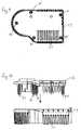
- FIG. 6is a top plan view of the charging system of FIG. 4 .
- FIG. 7is a top plan view similar to FIG. 6 illustrating the charging system of FIG. 4 with the housing top cover removed.
- FIG. 8is a elevational view along the line 8 - 8 of FIG. 7 .
- FIG. 9is a top plan view of the charging system housing bottom cover.
- FIG. 10is an elevation view illustrating the placement of the charging system housing top cover relative to the housing bottom cover.
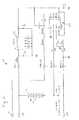
- FIG. 11is an exemplary circuit diagram of the battery of FIG. 1 .
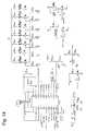
- FIG. 12is an exemplary circuit diagram of the battery of FIG. 2 .
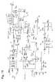
- FIG. 13is an exemplary circuit diagram of a buck circuit of the charging system of FIG. 4 .
- FIG. 14is an exemplary circuit diagram of a microprocessor and LED circuit of the charging system of FIG. 4 .
- FIG. 15is an exemplary circuit diagram of a flyback circuit of the charging system of FIG. 4 .
- FIGS. 1-3two exemplary battery packs 10 , 10 ′ of the present invention are shown.
- the battery pack 10 illustrated in FIG. 1utilizes Nickel Cadmium battery cells while the battery pack 10 ′ illustrated in FIGS. 2 and 3 utilizes Lithium Ion battery cells.
- Exemplary circuit diagrams for both battery packs 10 and 10 ′are illustrated in FIGS. 11 and 12 , respectively.
- Each battery pack 10 , 10 ′includes a main housing 12 with a stem portion 14 extending therefrom.
- the main housing 12 and the stem portion 14house the battery cells (not shown).
- the stem portion 14preferably houses one or more of the battery cells.
- the stem portion 14has a cylindrical body 13 extending from the main housing 12 to an end cap 15 .
- a pair of opposed openings 17are provided in the body 13 adjacent to the end cap 15 . The number and position of the openings 17 may be varied.
- the openings 17are configured to expose the battery electrical contacts 16 A and 16 B which are electrically interconnected with the battery cells and the battery communication contact 18 which is electrically interconnected with the battery onboard circuit 20 .
- each battery pack 10 and 10 ′includes various support keys 22 and alignment keys 24 extending radially outward from the stem portion body 13 .
- the support keys 22are configured to align with and rotatably engage support keyways in various portable tools.
- the support keys 22 and the alignment keys 24can be arranged in various configurations, including different widths, heights, positions, numbers and the like.
- the configuration of the support keys 22 and alignment key 24are configured such that the battery pack 10 , 10 ′ is properly aligned with the power tool or charging system 50 , as will be described hereinafter, such that the proper polarity of the contacts 16 A and 16 B is maintained.
- each specific support key 22 and alignment key 24 configurationcorresponds to a battery pack 10 , 10 ′ having a specific voltage such that the battery pack 10 , 10 ′ is useable only in power tools requiring such voltage and having corresponding keyways to receive the battery pack 10 , 10 ′. Since the configuration of the keys 22 and the alignment keyway 24 are distinct for each voltage, the different voltage battery packs would not be capable of inadvertent use with the wrong tool.
- the charging system 50generally includes a housing 52 comprising a top cover 51 and a bottom cover 53 .
- a battery stem receiving opening 60is defined through the top cover 51 .
- the opening 60includes one or more support key keyways 62 and one or more alignment key keyways 64 .
- the keyways 62 and 64are configured to receive various configurations of battery pack support keys 22 and alignment keys 24 , such that the charging system 50 provides a universal charger for various battery voltages.
- the support key keyways 62are typically wider than most, if not all of the support keys 22 , such that, relative to other voltage key configurations, the keys 22 can be moved circumferentially and still align with the keyways 62 .
- Stops 66are preferably provided within the opening 60 such that the battery pack stem 14 can only be rotated a given amount within the opening 60 .
- the charging system 50preferably includes a plug port 65 with male pins 67 configured to mate with the female plug of cords (not shown) useable with different input voltages. As illustrated in the circuit diagrams, the male pins 67 are associated with a voltage converter which allows the charging system to be utilized with different input voltages.
- the charging system 50includes a pair of opposed electrical contacts 72 A and 72 B configured to electrically connect with the battery pack contacts 16 A and 16 B.
- the configuration of the support keys 22 and alignment key 24 and the keyways 62 and 64are configured such that the battery pack 10 , 10 ′ is properly aligned with the charging system 50 such that the proper polarity of the contacts 16 A and 16 B is maintained.
- Each electrical contact 16 A, 16 Bpreferably includes a radially tapered portion 19 extending to an arcuate portion 21 .
- the tapered portions 19are configured to first contact the charger contacts 72 A and 72 B during rotation of the battery pack 10 , 10 ′ relative to the charging system 50 such that the charger contacts 72 A, 72 B ride along the tapered portions 19 and into final engagement with the arcuate portion 21 .
- the tapered portion 19may be made from conductive material, or alternatively, may be a non-conductive material.
- the battery pack contacts 16 A and 16 Bare circumferentially offset from and thereby disengaged from the charger contacts 72 A and 72 B. As such, during axial movement of the battery pack stem 14 into the opening 60 , the contacts 16 A, 16 B and 72 A, 72 B do not interfere with each other or apply any load upon each other.
- a communication contact 74extends from the circuit board 80 within the charging system 50 and is configured to engage the battery communication contact 18 . Electrical connection between the battery communication contact 18 and the communication contact 74 provides a digital link between the onboard circuit 20 in the battery pack 10 , 10 ′ and a microprocessor 90 or the like in the charging system 50 .
- An exemplary onboard circuit 20is the DS2438 manufactured by Dallas Semiconductor, the specifications of which are incorporated herein by reference. The functions of the onboard circuit 20 and the microprocessor 90 will be described hereinafter.
- Each of the batteries 10 , 10 ′includes a plurality of battery cells 30 , 30 ′.
- the battery cells 30 , 30 ′are connected with the battery contacts 16 A and 16 B and are also connected with the onboard circuit 20 .
- a voltage regulator 32which shuts down the battery when an over discharge is detected, is preferably provided in the battery circuit.
- a suitable voltage regulator 32is a model number LM9036-3.3 available from National Semiconductor.
- Each battery 10 , 10 ′includes a communication link between the onboard circuit 20 and the battery communication contact 18 . In the battery circuit of FIG.
- a voltage sensor 36is also provided to prevent over discharging.
- a suitable voltage sensor 36is a model number S-8242AAMB6T1GZ available from Seiko Instruments.
- the battery circuit of FIG. 12also includes a microprocessor 34 which controls operation of the battery 10 ′.
- a suitable microprocessoris a model number UPD78F9212GR available from NEC Electronics.
- a series of fuel gauge lights 38are connected to the microprocessor 34 and may be actuated using a push button 39 or the like to show the current fuel level directly on the battery 10 ′.
- the battery circuit of FIG. 12also includes a current sense resistor 31 and a MOFSET switch 33 which facilitates disabling of power in the battery 10 ′.
- a suitable MOFSET switchis a model number NP88N03KDG available from NEC Electronics.
- FIGS. 13-15are exemplary circuit diagrams of various portions of the charging system 50 and illustrate various components used therein.
- Mechanical structuresare also mounted on the circuit board 80 .
- a pair of heat sinks 82 and 83are mounted on the board 80 and are configured to remove heat from the electrical components.
- Each heat sink 82 , 83has a non-linear configuration to maximize the area of heat absorption surface.
- a fan 84 or the likeis mounted onto heat sink 82 .
- a slotted vent structure 85may be provided on the heat sink 82 in alignment with the fan 84 to draw or push air across the heat sink 82 to enhance cooling.
- the housing 52also has various vent slots 57 .
- the charger contacts 72 A and 72 B and the communication contact 74are each preferably mounted on the circuit board 80 via flexible mounts 73 such that when the top cover 51 is positioned relative to the bottom cover 53 , the contacts 72 A, 72 B and 74 may flex and align with the appropriate areas within the opening 60 .
- the circuit board 80is supported on supports 85 within the bottom cover 53 .
- the circuit board 80preferably is not initially secured to the bottom cover 53 and is slightly adjustable relative thereto.
- the top cover 51is placed onto the bottom cover 53 , and feet 87 depending therefrom pass through holes 89 in the circuit board 80 such that the feet 87 engage the supports 85 . Screws or the like are utilized to secure the feet 87 to the supports 85 and the circuit board 80 is maintained therebetween.
- the alignability of the circuit board 80 and the flexibility of the contacts 72 A, 72 B and 74allows the charging system 50 to be easily assembled.
- the battery onboard circuit 20 and the microprocessor 90communicate with one another to facilitate various charging functions as herein described.
- the various components utilized in carrying out these functionsare illustrated in the various circuit diagrams in FIGS. 11-15 .
- the onboard circuit 20preferably contains identifying indicia relating to the battery chemistry (i.e. NiCad vs. Lithium Ion), the battery voltage, the battery capacity and the like.
- This informationis communicated to the microprocessor 90 to inform the charging system 50 the type of battery pack 10 , 10 ′ that has been placed in the charging system 50 .
- the exchange of informationoccurs upon contact between the contacts 18 and 74 .
- the onboard circuit 20is independent of the stored charge within the battery pack 10 , 10 ′ and therefore the battery pack 10 , 10 ′ will be recognized by the charging system 50 even if the battery pack 10 , 10 ′ is completely drained.
- the onboard circuit 20has stored in its memory a charging protocol specific to the battery pack 10 , 10 ′.
- the onboard circuit 20may be configured to store data related to the battery pack 10 , 10 ′, for example, a counter of the number of charges, a history of discharge and charge cycles, a history of battery renewing and the like.
- the microprocessor 90can regulate the voltage output and the like such that the charging system 50 can charge batteries 10 , 10 ′ having different battery chemistries or having different voltages.
- the microprocessor 90is preferably configured to receive and display the current charge level of the battery pack 10 , 10 ′.
- the charging system 50includes a charge level indicator 93 which may include a series of LEDs or the like.
- the microprocessor 90is further configured to compare a current capacity of a battery pack 10 , 10 ′ to an original capacity of a battery pack 10 , 10 ′ (which is preferably stored in the memory of the onboard circuit 20 ) and, based thereon, recommend whether the battery pack 10 , 10 ′ should be renewed.
- a userdepresses the renew button 95 to start a renewing cycle.
- the microprocessor 90is configured to initiate a deep discharge of the battery pack 10 , 10 ′ and then recharge the battery pack 10 , 10 ′.
- the discharge button 95may be configured to light up upon detection of a condition in which a renew is recommend.
- the microprocessormay be configured to automatically renew the battery pack 10 , 10 ′ upon detection of such a condition.
Landscapes
- Engineering & Computer Science (AREA)
- General Chemical & Material Sciences (AREA)
- Chemical & Material Sciences (AREA)
- Chemical Kinetics & Catalysis (AREA)
- Electrochemistry (AREA)
- Manufacturing & Machinery (AREA)
- Power Engineering (AREA)
- Microelectronics & Electronic Packaging (AREA)
- Life Sciences & Earth Sciences (AREA)
- Biophysics (AREA)
- Computer Hardware Design (AREA)
- Charge And Discharge Circuits For Batteries Or The Like (AREA)
- Battery Mounting, Suspending (AREA)
Abstract
Description
Claims (18)
Priority Applications (2)
| Application Number | Priority Date | Filing Date | Title |
|---|---|---|---|
| US11/755,372US7863857B2 (en) | 2006-05-31 | 2007-05-30 | Cordless power tool battery and charging system therefore |
| US12/980,679US8299749B2 (en) | 2006-05-31 | 2010-12-29 | Cordless power tool battery and charging system therefore |
Applications Claiming Priority (2)
| Application Number | Priority Date | Filing Date | Title |
|---|---|---|---|
| US80995506P | 2006-05-31 | 2006-05-31 | |
| US11/755,372US7863857B2 (en) | 2006-05-31 | 2007-05-30 | Cordless power tool battery and charging system therefore |
Related Child Applications (1)
| Application Number | Title | Priority Date | Filing Date |
|---|---|---|---|
| US12/980,679ContinuationUS8299749B2 (en) | 2006-05-31 | 2010-12-29 | Cordless power tool battery and charging system therefore |
Publications (2)
| Publication Number | Publication Date |
|---|---|
| US20080007207A1 US20080007207A1 (en) | 2008-01-10 |
| US7863857B2true US7863857B2 (en) | 2011-01-04 |
Family
ID=38473966
Family Applications (2)
| Application Number | Title | Priority Date | Filing Date |
|---|---|---|---|
| US11/755,372Expired - Fee RelatedUS7863857B2 (en) | 2006-05-31 | 2007-05-30 | Cordless power tool battery and charging system therefore |
| US12/980,679ActiveUS8299749B2 (en) | 2006-05-31 | 2010-12-29 | Cordless power tool battery and charging system therefore |
Family Applications After (1)
| Application Number | Title | Priority Date | Filing Date |
|---|---|---|---|
| US12/980,679ActiveUS8299749B2 (en) | 2006-05-31 | 2010-12-29 | Cordless power tool battery and charging system therefore |
Country Status (3)
| Country | Link |
|---|---|
| US (2) | US7863857B2 (en) |
| EP (1) | EP1863108B1 (en) |
| CA (1) | CA2590874A1 (en) |
Cited By (7)
| Publication number | Priority date | Publication date | Assignee | Title |
|---|---|---|---|---|
| US20150183489A1 (en)* | 2012-03-16 | 2015-07-02 | Specialized Bicycle Components, Inc. | Bicycle with battery mount |
| US9917457B2 (en) | 2015-02-02 | 2018-03-13 | Black & Decker Inc. | Power tool with USB connection |
| US11108254B2 (en) | 2019-02-21 | 2021-08-31 | Omachron Intellectual Property Inc. | Cordless appliance, such as a surface cleaning apparatus and a charging unit therefor |
| US11190043B2 (en) | 2019-02-21 | 2021-11-30 | Omachron Intellectual Property Inc. | Cordless appliance, such as a surface cleaning apparatus, and a charging unit therefor |
| US11218017B2 (en)* | 2019-02-21 | 2022-01-04 | Omachron Intellectual Property Inc. | Cordless appliance, such as a surface cleaning apparatus, and a charging unit therefor |
| US20220021036A1 (en)* | 2020-07-20 | 2022-01-20 | Milwaukee Electric Tool Corporation | Systems, methods, and devices for increased charging speed of lithium-based battery packs |
| US11431224B2 (en) | 2017-02-15 | 2022-08-30 | Black & Decker Inc. | Power and home tools |
Families Citing this family (10)
| Publication number | Priority date | Publication date | Assignee | Title |
|---|---|---|---|---|
| US20080150474A1 (en)* | 2006-10-27 | 2008-06-26 | Ingersoll-Rand Company | Cordless power tool battery charging and analyzing system |
| WO2013099228A2 (en)* | 2011-12-30 | 2013-07-04 | Makita Corporation | Charger, battery pack charging system and cordless power tool system |
| JP6212910B2 (en)* | 2013-04-01 | 2017-10-18 | マックス株式会社 | Battery pack |
| USD711317S1 (en)* | 2013-04-18 | 2014-08-19 | Chervon (Hk) Limited | Charger |
| USD722955S1 (en)* | 2013-07-04 | 2015-02-24 | Ningbo Taller Electrical Appliance Co., Ltd. | Charger |
| EP2865612B1 (en) | 2013-10-22 | 2016-07-06 | Reemtsma Cigarettenfabriken GmbH | Package for tobacco products or tobacco related commodities or smoking devices and use thereof |
| JP6474846B2 (en)* | 2017-03-17 | 2019-02-27 | 株式会社マキタ | Battery pack for electric tools |
| EP3806273A1 (en) | 2019-10-11 | 2021-04-14 | Black & Decker Inc. | Power tool receiving different capacity batttery packs |
| TW202201169A (en)* | 2020-06-23 | 2022-01-01 | 大陸商光寶電子(廣州)有限公司 | Backup battery system |
| CN113263956A (en)* | 2021-04-23 | 2021-08-17 | 云南汇龙科技集团有限公司 | Electric motor car battery detects PCB circuit board device |
Citations (13)
| Publication number | Priority date | Publication date | Assignee | Title |
|---|---|---|---|---|
| DE3340882C1 (en) | 1983-11-11 | 1985-06-27 | Messerschmitt-Bölkow-Blohm GmbH, 8012 Ottobrunn | Device for temperature control and for reconditioning batteries from electro-chemical single cells |
| US5144217A (en) | 1989-03-03 | 1992-09-01 | Black & Decker Inc. | Cordless tool battery housing and charging system |
| DE4225088A1 (en) | 1991-07-31 | 1993-02-04 | Sanyo Electric Co | Battery discharging equipment with voltage measurement - has timer starting discharge at defined period after battery voltage falls below threshold |
| US5619117A (en) | 1982-06-07 | 1997-04-08 | Norand Corporation | Battery pack having memory |
| US5646508A (en) | 1994-11-10 | 1997-07-08 | Duracell, Inc. | Battery pack having a processor controlled battery operating system |
| EP0944153A2 (en) | 1998-03-18 | 1999-09-22 | Makita Corporation | Power tool charging system having a charge level indicator and charge control functions |
| US6075341A (en) | 1999-02-17 | 2000-06-13 | Black & Decker Inc. | Power pack charging system for a power tool |
| US6124698A (en)* | 1998-06-09 | 2000-09-26 | Makita Corporation | Battery charger |
| US6181103B1 (en) | 1997-05-27 | 2001-01-30 | Shu-Chin Chen | Advanced intelligent computer power management system |
| US6211644B1 (en)* | 1999-01-27 | 2001-04-03 | Telefonaktiebolaget Lm Ericsson | Method and apparatus for identifying a battery |
| EP1128517A2 (en) | 2000-02-24 | 2001-08-29 | Makita Corporation | Adapters for rechargeable battery packs |
| US20030082439A1 (en) | 2001-11-01 | 2003-05-01 | Makita Corporation | Battery packs suitable for use with battery powered appliances |
| WO2006044693A2 (en) | 2004-10-18 | 2006-04-27 | Black & Decker Inc. | Cordless power system |
Family Cites Families (7)
| Publication number | Priority date | Publication date | Assignee | Title |
|---|---|---|---|---|
| US5656917A (en)* | 1995-12-14 | 1997-08-12 | Motorola, Inc. | Battery identification apparatus and associated method |
| US6008620A (en)* | 1996-04-05 | 1999-12-28 | Sony Corporation | Battery charging device, method for charging battery pack and battery pack |
| WO2005112221A2 (en)* | 2004-05-04 | 2005-11-24 | O2Micro, Inc. | Cordless power tool with tool identification circuitry |
| CN101268568A (en) | 2005-09-20 | 2008-09-17 | 麦太保有限公司 | Handheld Power Tools |
| CN101268583B (en) | 2005-09-20 | 2010-08-25 | 麦太保有限公司 | Battery pack and hand-held electric tool |
| WO2007059784A1 (en) | 2005-11-23 | 2007-05-31 | Metabowerke Gmbh | Rechargeable battery for connection to a load |
| CA2602930C (en) | 2006-09-19 | 2013-08-06 | Hitachi Koki Co., Ltd. | Adaptor, assembly of battery pack and adaptor, and electric tool with the same |
- 2007
- 2007-05-30USUS11/755,372patent/US7863857B2/ennot_activeExpired - Fee Related
- 2007-05-30CACA002590874Apatent/CA2590874A1/ennot_activeAbandoned
- 2007-05-31EPEP07109337.1Apatent/EP1863108B1/ennot_activeNot-in-force
- 2010
- 2010-12-29USUS12/980,679patent/US8299749B2/enactiveActive
Patent Citations (17)
| Publication number | Priority date | Publication date | Assignee | Title |
|---|---|---|---|---|
| US5619117A (en) | 1982-06-07 | 1997-04-08 | Norand Corporation | Battery pack having memory |
| DE3340882C1 (en) | 1983-11-11 | 1985-06-27 | Messerschmitt-Bölkow-Blohm GmbH, 8012 Ottobrunn | Device for temperature control and for reconditioning batteries from electro-chemical single cells |
| US5144217A (en) | 1989-03-03 | 1992-09-01 | Black & Decker Inc. | Cordless tool battery housing and charging system |
| DE4225088A1 (en) | 1991-07-31 | 1993-02-04 | Sanyo Electric Co | Battery discharging equipment with voltage measurement - has timer starting discharge at defined period after battery voltage falls below threshold |
| US5355072A (en) | 1991-07-31 | 1994-10-11 | Sanyo Electric Co., Ltd. | Battery discharging apparatus |
| US5646508A (en) | 1994-11-10 | 1997-07-08 | Duracell, Inc. | Battery pack having a processor controlled battery operating system |
| US6181103B1 (en) | 1997-05-27 | 2001-01-30 | Shu-Chin Chen | Advanced intelligent computer power management system |
| EP0944153A2 (en) | 1998-03-18 | 1999-09-22 | Makita Corporation | Power tool charging system having a charge level indicator and charge control functions |
| US6229280B1 (en)* | 1998-03-18 | 2001-05-08 | Makita Corporation | Power tool charging system having a charge level indicator and charge control functions |
| US6124698A (en)* | 1998-06-09 | 2000-09-26 | Makita Corporation | Battery charger |
| US6211644B1 (en)* | 1999-01-27 | 2001-04-03 | Telefonaktiebolaget Lm Ericsson | Method and apparatus for identifying a battery |
| US6075341A (en) | 1999-02-17 | 2000-06-13 | Black & Decker Inc. | Power pack charging system for a power tool |
| EP1128517A2 (en) | 2000-02-24 | 2001-08-29 | Makita Corporation | Adapters for rechargeable battery packs |
| US20010017531A1 (en)* | 2000-02-24 | 2001-08-30 | Makita | Adapters for rechargeable battery packs |
| US20030082439A1 (en) | 2001-11-01 | 2003-05-01 | Makita Corporation | Battery packs suitable for use with battery powered appliances |
| WO2006044693A2 (en) | 2004-10-18 | 2006-04-27 | Black & Decker Inc. | Cordless power system |
| US20060087283A1 (en)* | 2004-10-18 | 2006-04-27 | Phillips Steven J | Cordless power system |
Cited By (11)
| Publication number | Priority date | Publication date | Assignee | Title |
|---|---|---|---|---|
| US20150183489A1 (en)* | 2012-03-16 | 2015-07-02 | Specialized Bicycle Components, Inc. | Bicycle with battery mount |
| US9580140B2 (en)* | 2012-03-16 | 2017-02-28 | Specialized Bicycle Components, Inc. | Bicycle with battery mount |
| US9917457B2 (en) | 2015-02-02 | 2018-03-13 | Black & Decker Inc. | Power tool with USB connection |
| US11431224B2 (en) | 2017-02-15 | 2022-08-30 | Black & Decker Inc. | Power and home tools |
| US11664703B2 (en) | 2017-02-15 | 2023-05-30 | Black & Decker Inc. | Power and home tools |
| US11108254B2 (en) | 2019-02-21 | 2021-08-31 | Omachron Intellectual Property Inc. | Cordless appliance, such as a surface cleaning apparatus and a charging unit therefor |
| US11190043B2 (en) | 2019-02-21 | 2021-11-30 | Omachron Intellectual Property Inc. | Cordless appliance, such as a surface cleaning apparatus, and a charging unit therefor |
| US11218017B2 (en)* | 2019-02-21 | 2022-01-04 | Omachron Intellectual Property Inc. | Cordless appliance, such as a surface cleaning apparatus, and a charging unit therefor |
| US11715967B2 (en) | 2019-02-21 | 2023-08-01 | Omachron Intellectual Property Inc. | Surface cleaning apparatus, and a charging unit therefor |
| US12057734B2 (en) | 2019-02-21 | 2024-08-06 | Omachron Intellectual Property Inc. | Surface cleaning apparatus, and a charging unit therefor |
| US20220021036A1 (en)* | 2020-07-20 | 2022-01-20 | Milwaukee Electric Tool Corporation | Systems, methods, and devices for increased charging speed of lithium-based battery packs |
Also Published As
| Publication number | Publication date |
|---|---|
| US20080007207A1 (en) | 2008-01-10 |
| US20110204848A1 (en) | 2011-08-25 |
| EP1863108A3 (en) | 2008-02-27 |
| US8299749B2 (en) | 2012-10-30 |
| EP1863108B1 (en) | 2013-11-13 |
| EP1863108A2 (en) | 2007-12-05 |
| CA2590874A1 (en) | 2007-11-30 |
Similar Documents
| Publication | Publication Date | Title |
|---|---|---|
| US7863857B2 (en) | Cordless power tool battery and charging system therefore | |
| US20080150474A1 (en) | Cordless power tool battery charging and analyzing system | |
| US11682910B2 (en) | Method of operating a lithium-based battery pack for a hand held power tool | |
| US20180198292A1 (en) | Universal Power Tool Battery Pack And Recharging System | |
| JP4624012B2 (en) | Battery pack | |
| CN102933353B (en) | Electric tool | |
| US6441589B1 (en) | Portable battery recharge station | |
| US10074994B2 (en) | Power tool system | |
| CN217607501U (en) | Charger adapted to charge either of first battery pack and second battery pack, and kit | |
| US20050194166A1 (en) | High torque electromotive tool | |
| EP1906470B1 (en) | Cordless power tool battery charging system | |
| JP3130892U (en) | Charging system | |
| AU2020102987A4 (en) | Battery charger for multiple battery packs |
Legal Events
| Date | Code | Title | Description |
|---|---|---|---|
| AS | Assignment | Owner name:INGERSOLL-RAND COMPANY, NEW JERSEY Free format text:ASSIGNMENT OF ASSIGNORS INTEREST;ASSIGNORS:BECKER, DANIEL JAY;BALL, JR., WILLIAM M.;HOLTZMAN, GIL;AND OTHERS;REEL/FRAME:019808/0119 Effective date:20070827 | |
| STCF | Information on status: patent grant | Free format text:PATENTED CASE | |
| FPAY | Fee payment | Year of fee payment:4 | |
| MAFP | Maintenance fee payment | Free format text:PAYMENT OF MAINTENANCE FEE, 8TH YEAR, LARGE ENTITY (ORIGINAL EVENT CODE: M1552) Year of fee payment:8 | |
| AS | Assignment | Owner name:INGERSOLL-RAND INDUSTRIAL U.S., INC., NORTH CAROLI Free format text:ASSIGNMENT OF ASSIGNORS INTEREST;ASSIGNOR:INGERSOLL-RAND COMPANY;REEL/FRAME:051316/0478 Effective date:20191130 Owner name:INGERSOLL-RAND INDUSTRIAL U.S., INC., NORTH CAROLINA Free format text:ASSIGNMENT OF ASSIGNORS INTEREST;ASSIGNOR:INGERSOLL-RAND COMPANY;REEL/FRAME:051316/0478 Effective date:20191130 | |
| AS | Assignment | Owner name:CITIBANK, N.A., AS ADMINISTRATIVE AGENT AND COLLATERAL AGENT, DELAWARE Free format text:SECURITY INTEREST;ASSIGNORS:CLUB CAR, LLC;MILTON ROY, LLC;HASKEL INTERNATIONAL, LLC;AND OTHERS;REEL/FRAME:052072/0381 Effective date:20200229 | |
| FEPP | Fee payment procedure | Free format text:MAINTENANCE FEE REMINDER MAILED (ORIGINAL EVENT CODE: REM.); ENTITY STATUS OF PATENT OWNER: LARGE ENTITY | |
| LAPS | Lapse for failure to pay maintenance fees | Free format text:PATENT EXPIRED FOR FAILURE TO PAY MAINTENANCE FEES (ORIGINAL EVENT CODE: EXP.); ENTITY STATUS OF PATENT OWNER: LARGE ENTITY | |
| STCH | Information on status: patent discontinuation | Free format text:PATENT EXPIRED DUE TO NONPAYMENT OF MAINTENANCE FEES UNDER 37 CFR 1.362 | |
| FP | Lapsed due to failure to pay maintenance fee | Effective date:20230104 | |
| AS | Assignment | Owner name:INGERSOLL-RAND INDUSTRIAL U.S., INC., NORTH CAROLINA Free format text:RELEASE OF PATENT SECURITY INTEREST;ASSIGNOR:CITIBANK, N.A., AS COLLATERAL AGENT;REEL/FRAME:067401/0811 Effective date:20240510 Owner name:HASKEL INTERNATIONAL, LLC, CALIFORNIA Free format text:RELEASE OF PATENT SECURITY INTEREST;ASSIGNOR:CITIBANK, N.A., AS COLLATERAL AGENT;REEL/FRAME:067401/0811 Effective date:20240510 Owner name:MILTON ROY, LLC, NORTH CAROLINA Free format text:RELEASE OF PATENT SECURITY INTEREST;ASSIGNOR:CITIBANK, N.A., AS COLLATERAL AGENT;REEL/FRAME:067401/0811 Effective date:20240510 |