US7862594B2 - Polyaxial pedicle screw assembly - Google Patents
Polyaxial pedicle screw assemblyDownload PDFInfo
- Publication number
- US7862594B2 US7862594B2US11/045,908US4590805AUS7862594B2US 7862594 B2US7862594 B2US 7862594B2US 4590805 AUS4590805 AUS 4590805AUS 7862594 B2US7862594 B2US 7862594B2
- Authority
- US
- United States
- Prior art keywords
- assembly
- screw head
- screw
- bone
- fixator component
- Prior art date
- Legal status (The legal status is an assumption and is not a legal conclusion. Google has not performed a legal analysis and makes no representation as to the accuracy of the status listed.)
- Expired - Fee Related, expires
Links
Images


Classifications
- A—HUMAN NECESSITIES
- A61—MEDICAL OR VETERINARY SCIENCE; HYGIENE
- A61B—DIAGNOSIS; SURGERY; IDENTIFICATION
- A61B17/00—Surgical instruments, devices or methods
- A61B17/56—Surgical instruments or methods for treatment of bones or joints; Devices specially adapted therefor
- A61B17/58—Surgical instruments or methods for treatment of bones or joints; Devices specially adapted therefor for osteosynthesis, e.g. bone plates, screws or setting implements
- A61B17/68—Internal fixation devices, including fasteners and spinal fixators, even if a part thereof projects from the skin
- A61B17/70—Spinal positioners or stabilisers, e.g. stabilisers comprising fluid filler in an implant
- A61B17/7001—Screws or hooks combined with longitudinal elements which do not contact vertebrae
- A61B17/7035—Screws or hooks, wherein a rod-clamping part and a bone-anchoring part can pivot relative to each other
- A61B17/7037—Screws or hooks, wherein a rod-clamping part and a bone-anchoring part can pivot relative to each other wherein pivoting is blocked when the rod is clamped
- A—HUMAN NECESSITIES
- A61—MEDICAL OR VETERINARY SCIENCE; HYGIENE
- A61B—DIAGNOSIS; SURGERY; IDENTIFICATION
- A61B17/00—Surgical instruments, devices or methods
- A61B17/56—Surgical instruments or methods for treatment of bones or joints; Devices specially adapted therefor
- A61B17/58—Surgical instruments or methods for treatment of bones or joints; Devices specially adapted therefor for osteosynthesis, e.g. bone plates, screws or setting implements
- A61B17/68—Internal fixation devices, including fasteners and spinal fixators, even if a part thereof projects from the skin
- A61B17/70—Spinal positioners or stabilisers, e.g. stabilisers comprising fluid filler in an implant
- A61B17/7001—Screws or hooks combined with longitudinal elements which do not contact vertebrae
- A61B17/7032—Screws or hooks with U-shaped head or back through which longitudinal rods pass
Definitions
- the embodiments of the inventiongenerally relate to medical devices and assemblies, and more particularly to an orthopedic surgical implant assembly used in the field of surgical lumbar, thoracic and cervical spine treatment.
- Surgical procedures treating spinal injuriesare one of the most complex and challenging surgeries for both the patient and the surgeon.
- surgeonsmay attempt to “fuse” them together by attaching screw-like devices into the pedicles of the spine and thereby connecting several vertebrae (typically two or more) using a semi-rigid rod.
- screw-like devicestypically two or more
- several vertebraetypically two or more
- most surgeonsmust bend the rod (causing notches thereby reducing fatigue resistance) before placing them into two or more non-aligned pedicle screws in order to properly stabilize the pedicle screw assembly within the patient's body.
- an embodiment of the inventionprovides an assembly comprising a screw head comprising a bulbous end; a fixator component configured for receiving the bulbous end of the screw head; a pin mounted in the screw head; and a blocker adapted to engage the screw head.
- the screw headcomprises a slot configured for receiving a longitudinal member.
- the fixator componentcomprises a concave socket configured for receiving the bulbous end of the screw head.
- the fixator componentcomprises a threaded end opposite the concave socket and configured for attaching to a bone.
- the pinengages the fixator component and a bottom portion of the longitudinal member.
- the blockersecures a top portion of the longitudinal member.
- the pincomprises an upper saddle portion and a lower tip portion.
- the pincomprises a multi-part assembly.
- the pinmay be made of one part that may be coated or it can be made of two parts (an upper and lower portion) comprising different materials, with the lower portion comprising a mechanically harder material than the upper portion.
- the screw head and the fixator componentcomprise a first material, and the lower tip portion of the pin comprises a material having a higher material hardness and compressive yield strength than the first material.
- the assemblymay further comprise a wear resistant ceramic coating over the screw head and the fixator component.
- the screw headfurther comprises two opposed upright ends separated by the slot, wherein each of the opposed upright ends comprise an inner wall and an outer wall, wherein the inner wall comprises wall threads, and wherein the outer wall comprises grooves.
- the blockercomprises blocker threads configured around an outer perimeter of the blocker, the blocker threads being dimensioned and configured to mate with the wall threads.
- the upper saddle portion of the pinmay comprise a slot or slots.
- the bulbous end of the screw headmay comprise a plurality of slots terminating at an opening at a tip of the bulbous end.
- the bulbous end of the screw headpreferably comprises a gap configured to receive the pin.
- the concave socket of the fixator componentcomprises an inner portion adapted to receive the bulbous end of the screw head; and preferably a dimpled outer portion or other geometries.
- the fixator componentcomprises any of a bone screw and a hook.
- a pedicle fixation assemblycomprising a screw head comprising a male bulbous end; a bone fixator component comprising a female concave semi-spherical socket for receiving the screw head; a locking saddle pin for engaging the screw head and the bone fixator component; and a blocker for engaging the screw head and for securing the longitudinal member.
- Still another aspect of the inventionprovides a method of assembling a pedicle fixation assembly, wherein the method comprises attaching a screw head to a bone fixator component; securing the bone fixator component in a bone; securing a locking pin in the screw head; engaging the locking pin with the bone fixator component; inserting a longitudinal member in the screw head; and inserting a blocker in the screw head, wherein the screw head comprises a male bulbous end and the bone fixator component comprises a female concave semi-spherical socket for receiving the screw head.
- the methodfurther comprises coating the screw head and the bone fixator component with a wear resistant ceramic coating.
- the bone fixator componentmay be configured as any of a bone screw and a hook.
- the embodiments of the inventionprovide a pedicle screw assembly implant device, which may be used anteriorly or posteriorly, and which is capable of being utilized in surgeries to achieve anterior lumbar interbody fusion, posterior lumbar interbody fusion, transverse lumbar interbody fusion, correct degenerative disc disease, adult and pediatric scoliosis as a fixation device, and posterior cervical fusion.
- the embodiments of the inventionprovide a polyaxial spinal screw that can become rigid similar to a monoaxial screw inter-operatively on demand.
- the embodiments of the inventionalso offer the surgeon more lateral range of motion than conventional products by utilizing the space under the screw head to provide a bigger arc of rotation.
- the saddle pin componentoffers the flexibility to use a diametrical range of spinal rods instead of a fixed size rod.
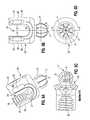
- FIG. 1illustrates an exploded view of the screw assembly according to an embodiment of the invention
- FIG. 2illustrates an exploded view of the screw assembly during a step in the manufacturing according to an embodiment of the invention
- FIG. 3illustrates an exploded view of the screw assembly during a step in the manufacturing according to an embodiment of the invention
- FIG. 4illustrates an exploded view of the screw assembly during a step in the manufacturing according to an embodiment of the invention
- FIG. 5illustrates a perspective view of the fully assembled screw assembly in a monoaxial position according to an embodiment of the invention
- FIG. 6illustrates a perspective view of the fully assembled screw assembly in a polyaxial position according to an embodiment of the invention
- FIG. 7is a partial internal view of the screw assembly in a monoaxial position according to an embodiment of the invention.
- FIG. 8is a partial internal view of the screw assembly in a polyaxial position according to an embodiment of the invention.
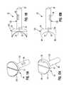
- FIGS. 9A through 9Hare isolated views of the screw head according to an embodiment of the invention.
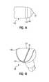
- FIG. 10Ais a perspective view of a bone fixator assembly according to a second embodiment of the invention.
- FIG. 10Bis a detailed view of the hook of the bone fixator assembly of FIG. 10A according to the second embodiment of the invention.
- FIGS. 11A through 11Bare detailed views of the saddle pin according to a first embodiment of the invention.
- FIGS. 12A through 12Bare detailed views of the saddle pin according to a second embodiment of the invention.
- FIGS. 13 through 14 aare detailed views of the saddle pin according to a third embodiment of the invention.
- FIGS. 15A through 15Care detailed views of the blocker according to an embodiment of the invention.
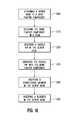
- FIG. 16is a flow diagram illustrating a preferred method according to an embodiment of the invention.
- FIGS. 1 through 16where similar reference characters denote corresponding features consistently throughout the figures, there are shown preferred embodiments of the invention.
- FIGS. 1 through 6provide an exploded view of the pedicle screw assembly 1 according to a first embodiment of the invention.
- the screw assembly 1comprises a bone screw (fixator component) 10 having a threaded end 11 for engaging a bone (not shown) and a concave female socket end 12 for engaging and receiving the screw head 20 .
- the screw head 20is first snapped into place in the bone screw 10 as shown in FIG. 2 . Then, as shown in FIGS. 3 and 9B , the saddle pin 30 snaps into place in the lower base portion 25 of the screw head 20 , which includes a groove 26 (best seen in FIG. 7 ) for receiving the saddle pin 30 .
- the screw assembly 1is prepared for ultra sonic cleaning to remove any impurities and subsequently may be shipped in this manufactured format (with the saddle pin 30 connected to the screw head 20 , which is connected to the bone screw 10 ).
- FIG. 7shows that the female spherical socket 12 of the bone screw 10 has an undercut 7 to allow the screw head 20 to pivot freely but not to disassemble once the saddle pin 30 is inserted.
- the thread 11 of the bone screw 10may be a multiple lead thread to allow faster insertion into a bone. This thread 11 may be tapered on the minor diameter while cylindrical on the major diameter to allow a new “bite” with every turn and to accommodate more thread depth towards the bottom of the bone screw 10 for the cancellous bone.
- FIG. 4illustrates the assembled view of the screw assembly 1 in the straight monoaxial direction.
- the threads 11 of the bone screw 10are double lead, which provides greater surface contact with the bone, but drives at 4 mm/revolution.
- FIG. 6illustrates the screw assembly 1 in a rotationally articulated position. The maximum angulation is 25 degrees/side, but the medial correction/travel of the longitudinal member 50 is 3.8 mm/side, which is nearly twice of what most conventional screws offer.
- FIG. 7the locking mechanism of the screw assembly 1 is illustrated.
- a two step locking processis shown.
- the first positionexpands the screw head 20 into the bone screw 10
- the second positionpermanently turns the polyaxial screw assembly 1 into a monoaxial screw assembly 1 by using the saddle pin 30 to lock the assembly 1 .
- the screw assembly 1can be permanently locked in any desired position (within the 25 degree guideline) simply by sending the longitudinal member 50 “home” or by using a tool (not shown) to lock the assembly 1 at the desired angle.
- FIG. 9Aillustrates the overall configuration of the screw head 20 .
- FIG. 9Billustrates a front view of the screw head 20 .
- FIG. 9Cis a cross-sectional view from cut-line “CC” of FIG. 9D .
- FIG. 9Eis a cross-sectional view from cut-line “BB” of FIG. 9F and
- FIG. 9Gis a cross-sectional view from cut-line “AA” of FIG. 9F .
- FIG. 9His an enlarged detailed view of the encircled area “A” of FIG. 9G illustrating the threaded inner portion 23 in more detail. As shown in FIGS.
- the screw head 20includes a bulbous (spherical) male end 21 for engaging the concave female socket 12 of the bone screw 10 .
- the screw head 20also includes a pair of upright ends 22 opposite the bulbous male end 21 , wherein the upright ends 22 comprise a threaded inner portion 23 for engaging the blocker 40 .
- the screw head 20includes a generally open U-shaped inner portion 24 for receiving the saddle pin 30 and the longitudinal member 50 .
- the male end 21 of the screw head 20includes a plurality (for example, four or more) slots 6 that allow the male end 21 to expand into the female spherical socket 12 of the bone screw 10 at any allowable angle once the saddle pin 30 is forced through.
- the screw head 20is pivoting inside the female socket end 12 of the bone screw 10 , the assembly 1 is allowed to be inserted deeper into the bone without having the bone or anatomy prematurely limit the range of angulations of the screw head 20 .
- the screw head 20further includes external features or cuts 29 that assist in accommodating surgical instrumentation during manipulation and assembly during the surgical procedure. These cuts 29 allow various instruments (not shown) to firmly and positively hold and manipulate the screw head 20 on one side or both sides of screw head 20 .
- FIG. 10Ais a perspective view of a bone fixator assembly according to a second embodiment of the invention, wherein the bone fixator component is configured as a hook 60 .
- the hook 60is further illustrated in FIG. 10B .
- the hook 60includes a concave socket 12 having an inner portion 9 adapted to receive the bulbous end 21 of the screw head 20 ; and a dimpled outer portion 8 .
- the hook 60further includes a pair of arms 61 , 62 connected by a connection arm 64 .
- a space 63separates the arms 61 , 62 from one another.
- the arms 61 , 62are configured to receive an additional member (not shown) for subsequent attachment to the bone.
- the several embodiments of the saddle pin 30are shown in FIGS. 11A through 14 .
- the saddle pin 30provides a proper seat for the longitudinal member 50 and avoids notching a typical titanium longitudinal member 50 (titanium is very notch sensitive). Furthermore, the saddle pin 30 allows one to accommodate multiple sizes of longitudinal members 50 in the same screw assembly system 1 which is a first for a titanium system because of the above-mentioned notching factors.
- the saddle pin 30is configured with a slot 32 through the center to allow expansion of the upper portion (head) 131 of the saddle pin 30 .
- the bottom 35 of the saddle pin head 131is angled to allow the saddle pin 30 to accept a larger-sized longitudinal member 50 .
- the saddle pin 30initially expands the male sphere 21 of the screw head 20 into the female spherical socket 12 in the bone screw 10 causing the screw assembly system 1 to lock or start locking (i.e., causing the male sphere 21 of the screw head 20 to lock in the female spherical socket 12 of the bone screw 10 ).
- the saddle pin 30then “digs” into the female spherical socket 12 of the bone screw 10 to provide a secondary locking force to avoid bending failure of the assembly 1 .
- FIGS. 11A through 11Billustrate a first embodiment of the saddle pin 30 .
- the saddle pin 30generally includes an upper portion 131 and a lower portion 132 .
- the upper portionincludes a slot 32 , which is configured from the lowest area 33 of the upper portion 131 into the upper area 34 of the lower portion 132 of the saddle pin 30 .
- a secondary locking mechanism 36may be configured on the lower portion 132 of the saddle pin to further achieve locking of the saddle pin 30 once it is inserted in the screw head 20 .
- the lower portion 132 of the saddle pin 30terminates with a pointed end 37 to allow for digging into the female socket 12 of the bone screw 10 .
- FIGS. 12A through 12Billustrate a second embodiment of the saddle pin 30 .
- the difference between the first and second embodiments of the saddle pin 30is that the upper portion of the saddle pin 131 in the second embodiment includes two generally flat upper opposed ends 38 to more matingly configure with the geometry of the screw head 20 and the longitudinal member 50 .
- FIGS. 13 through 14illustrate a third embodiment of the saddle pin 30 .
- the saddle pin 30comprises two parts: an upper portion 131 preferably comprising titanium and a lower portion 132 which is preferably ceramic.
- the material of the lower portion 132 of the saddle pin 30is preferably ceramic and has a higher hardness and compressive yield strength than the comparative hardness and compressive yield strength of Ti 6 Al 4 V, which is the material which may be used in constructing the screw head 20 and bone screw 10 .
- the upper portion 131 of the saddle pin 30includes a slot 32 in the seat portion 133 and tapered angled ends 134 .
- the saddle pin 30i.e., the upper portion 131 and the ceramic tip 132 are assembled last in the overall process. Specifically, the screw head 20 snaps into the bone screw 10 . Then, the ceramic tip 132 slides into the screw head 20 , and finally the titanium saddle (upper portion) 131 is press fitted into the screw head 20 keeping everything in place and oriented in a relaxed state.
- the lower portion 132 of the saddle pinterminates with a series of cascading walls 137 , 138 having sloped angles, terminating with the pointed end 37 for attachment into the screw head 20 /bone screw 10 assembly.
- the material properties of the saddle pin tip 132are such that it prevents the deformation on the saddle pin 30 before the saddle pin 30 gives the proper bending and penetrating effects onto the screw head 20 /bone screw 10 assembly.
- Examples of the types of materials used for the saddle pin pointed end 37include ZyranoxTMand HIP VitoxTM, both of which are available from Morgan Advanced Ceramics, United Kingdom.
- the blocker 40which is further illustrated in FIGS. 15A through 15C , includes a standard buttress thread 41 configured along an outer perimeter of the blocker 40 .
- the blocker 40helps to secure the longitudinal member 50 inside the screw head 40 .
- the threads 41 of the blocker 40are configured to engage the threads 23 of the screw head 20 . Additionally, the blocker 40 aids in preventing the expansion of the screw head 20 when torqued on the longitudinal member 50 , directing the counterforce more vertically than horizontally.
- the top 42 of the blocker 40has a fastening feature 43 such as a hex or square lock feature to allow high torque to be applied in locking the assembly 1 .
- the blocker 40may be configured with a free rotating saddle (not shown) to accommodate, via tangential contact, the longitudinal member 50 and help to further prevent notching of the titanium alloy used to construct the longitudinal member 50 .
- the blocker 40may have a “timed” thread 41 that is consistently and precisely related to the blocker driving tool (not shown) to help calculate the torsional and vertical position of the blocker 40 thereby assisting the torque measurement applied to the blocker 40 .
- FIG. 16illustrates a method of assembling a pedicle screw assembly 1 , wherein the method comprises attaching ( 200 ) a screw head 20 to a bone fixator component 10 ; securing ( 210 ) the bone fixator component 10 in the bone (not shown); securing ( 220 ) a saddle pin 30 in the screw head 20 ; engaging ( 230 ) the saddle pin 30 with the bone fixator component 10 ; inserting ( 240 ) a longitudinal member 50 in the screw head 20 ; and inserting ( 250 ) a blocker 40 in the screw head 20 .
- the embodiments of the inventionprovide an axial movement of the screw head up to 25 degrees in any plane. Moreover, the embodiments of the invention allow for greater medial translation of the longitudinal member 50 (nearly 4 mm compared to the conventional devices which are generally limited to 2 mm).
- the inventive assembly 1can be used as a dynamic rod system to complement artificial discs.
- the outside of the spherical joint part 21 of the screw head 20 and the inner spherical surface 9 of the bone screw cup 12are coated with a wear resistant ceramic coating.
- the saddle pin 30is not digging into the bone screw 10 and in fact is configured at a shorter length than some of the other embodiments.
- This systemallows some motion instead of rigid fixation and shares the load with the artificial disc disallowing excessive forces being applied to the artificial disc and increasing its functional life. For example, this occurs as a result of the ceramic coating, which may be used in the embodiments of the invention.
- the spherical joint 21 of the screw head 20 and the inner spherical surface 12 of the bone screw 10have lower friction and higher wear resistance characteristics, thus improving the overall characteristics of the screw assembly 1 .
- the embodiments of the inventionprovide an assembly 1 comprising a screw head 20 comprising a bulbous end 21 ; a fixator component 10 configured for receiving the bulbous end 21 of the screw head 20 ; a pin 30 mounted in the screw head 20 ; and a blocker 40 adapted to engage the screw head 20 .
- the screw head 20comprises a slot 24 configured for receiving a longitudinal member 50 .
- the fixator component 10comprises a concave socket 12 configured for receiving the bulbous end 21 of the screw head 20 .
- the fixator component 10also comprises a threaded end 11 opposite the concave socket 12 and configured for attaching to a bone.
- the pin 30engages the fixator component 10 and a bottom portion 51 of the longitudinal member 50 .
- the blocker 40secures a top portion 52 of the longitudinal member 50 .
- the pin 30comprises an upper saddle portion 131 and a lower tip portion 132 .
- the pin 30may comprise a multi-part assembly.
- the upper saddle portion 131 of the pin 30comprises titanium and the lower tip portion 132 of the pin 30 comprises a ceramic material.
- the lower tip portion 132comprises a mechanically harder material than the upper saddle portion 131 .
- the screw head 20 and the fixator component 10comprise a first material, and the lower tip portion 132 of the pin 30 comprises a material having a higher material hardness and compressive yield strength than the first material.
- the assembly 1further comprises a wear resistant ceramic coating (not shown) over the screw head 20 and the fixator component 10 .
- the screw head 20further comprises two opposed upright ends 22 separated by the slot 24 , wherein each of the opposed upright ends 22 comprise an inner wall 27 and an outer wall 28 , wherein the inner wall 27 comprises wall threads 23 , and wherein the outer wall 28 comprises grooves (cuts) 29 .
- the blocker 40comprises blocker threads 41 configured around an outer perimeter 42 of the blocker 40 , the blocker threads 41 being dimensioned and configured to mate with the wall threads 23 .
- the upper saddle portion 131 of the pin 30comprises a slot 32 .
- the bulbous end 21 of the screw head 20comprises a plurality of slots 6 terminating at an opening 4 at a tip 3 of the bulbous end 21 .
- the bulbous end 21 of the screw head 20comprises a gap 19 configured to receive the pin 30 .
- the concave socket 12 of the fixator component 10comprises an inner portion 9 adapted to receive the bulbous end 21 of the screw head 20 ; and a dimpled outer portion 8 .
- the fixator component 10is configured as any of a threaded bone screw 10 (as shown in FIGS. 1 through 8 ) and a hook 60 (as shown in FIGS. 10A and 10B ) according to the several embodiments of the invention.
- the embodiments of the inventionprovide a pedicle screw assembly implant device 1 , which may be used anteriorly or posteriorly, and which is capable of being utilized in surgeries to achieve anterior lumbar interbody fusion, posterior lumbar interbody fusion, transverse lumbar interbody fusion, correct degenerative disc disease, adult and pediatric scoliosis as a fixation device, and posterior cervical fusion.
- the embodiments of the inventionprovide a polyaxial spinal screw assembly 1 that can become rigid similar to a monoaxial screw inter-operatively on demand.
- the embodiments of the inventionalso offer the surgeon more lateral range of motion than conventional products by utilizing the space under the screw head 20 to provide a bigger arc of rotation.
- the saddle pin 30 componentoffers the flexibility to use a diametrical range of spinal longitudinal members 50 instead of a fixed size longitudinal member.
Landscapes
- Health & Medical Sciences (AREA)
- Orthopedic Medicine & Surgery (AREA)
- Life Sciences & Earth Sciences (AREA)
- Neurology (AREA)
- Surgery (AREA)
- Molecular Biology (AREA)
- Veterinary Medicine (AREA)
- Biomedical Technology (AREA)
- Heart & Thoracic Surgery (AREA)
- Medical Informatics (AREA)
- Nuclear Medicine, Radiotherapy & Molecular Imaging (AREA)
- Animal Behavior & Ethology (AREA)
- General Health & Medical Sciences (AREA)
- Public Health (AREA)
- Engineering & Computer Science (AREA)
- Surgical Instruments (AREA)
- Excavating Of Shafts Or Tunnels (AREA)
- Medicines Containing Plant Substances (AREA)
- Pharmaceuticals Containing Other Organic And Inorganic Compounds (AREA)
- Non-Disconnectible Joints And Screw-Threaded Joints (AREA)
- Dowels (AREA)
- Earth Drilling (AREA)
Abstract
Description
Claims (22)
Priority Applications (13)
| Application Number | Priority Date | Filing Date | Title |
|---|---|---|---|
| US11/045,908US7862594B2 (en) | 2004-02-27 | 2005-01-28 | Polyaxial pedicle screw assembly |
| EP05723528AEP1725175B1 (en) | 2004-02-27 | 2005-02-23 | Polyaxial pedicle screw assembly |
| PCT/US2005/005681WO2005086651A2 (en) | 2004-02-27 | 2005-02-23 | Polyaxial pedicle screw assembly |
| DE602005020259TDE602005020259D1 (en) | 2004-02-27 | 2005-02-23 | POLYAXIALPEDIKELSCHRAUBENANORDUNG |
| JP2007500936AJP4498413B2 (en) | 2004-02-27 | 2005-02-23 | Multi-axis pattern joining screw assembly |
| ES05723528TES2340938T3 (en) | 2004-02-27 | 2005-02-23 | POLYAXIAL PEDICULAR SCREW ASSEMBLY. |
| AT05723528TATE462363T1 (en) | 2004-02-27 | 2005-02-23 | POLYAXIAL PEDICLE SCREW ASSEMBLY |
| US11/608,856US8097020B2 (en) | 2004-02-27 | 2006-12-11 | Pedicle dynamic facet arthroplasty system and method |
| US11/608,857US7892257B2 (en) | 2004-02-27 | 2006-12-11 | Spring loaded, load sharing polyaxial pedicle screw assembly and method |
| US12/909,811US8652178B2 (en) | 2004-02-27 | 2010-10-21 | Polyaxial pedicle screw assembly and method |
| US12/917,328US20110046684A1 (en) | 2004-02-27 | 2010-11-01 | Screw Assembly and Method |
| US12/940,031US20110054546A1 (en) | 2004-02-27 | 2010-11-04 | Polyaxial Pedicle Screw Assembly |
| US13/005,227US8439954B2 (en) | 2004-02-27 | 2011-01-12 | Spring-loaded, load sharing polyaxial pedicle screw assembly and method |
Applications Claiming Priority (3)
| Application Number | Priority Date | Filing Date | Title |
|---|---|---|---|
| US54854304P | 2004-02-27 | 2004-02-27 | |
| US56565804P | 2004-04-27 | 2004-04-27 | |
| US11/045,908US7862594B2 (en) | 2004-02-27 | 2005-01-28 | Polyaxial pedicle screw assembly |
Related Child Applications (5)
| Application Number | Title | Priority Date | Filing Date |
|---|---|---|---|
| US11/608,857Continuation-In-PartUS7892257B2 (en) | 2004-02-27 | 2006-12-11 | Spring loaded, load sharing polyaxial pedicle screw assembly and method |
| US11/608,856Continuation-In-PartUS8097020B2 (en) | 2004-02-27 | 2006-12-11 | Pedicle dynamic facet arthroplasty system and method |
| US12/909,811DivisionUS8652178B2 (en) | 2004-02-27 | 2010-10-21 | Polyaxial pedicle screw assembly and method |
| US12/917,328Continuation-In-PartUS20110046684A1 (en) | 2004-02-27 | 2010-11-01 | Screw Assembly and Method |
| US12/940,031ContinuationUS20110054546A1 (en) | 2004-02-27 | 2010-11-04 | Polyaxial Pedicle Screw Assembly |
Publications (2)
| Publication Number | Publication Date |
|---|---|
| US20050192571A1 US20050192571A1 (en) | 2005-09-01 |
| US7862594B2true US7862594B2 (en) | 2011-01-04 |
Family
ID=34890975
Family Applications (3)
| Application Number | Title | Priority Date | Filing Date |
|---|---|---|---|
| US11/045,908Expired - Fee RelatedUS7862594B2 (en) | 2004-02-27 | 2005-01-28 | Polyaxial pedicle screw assembly |
| US12/909,811Active2026-08-29US8652178B2 (en) | 2004-02-27 | 2010-10-21 | Polyaxial pedicle screw assembly and method |
| US12/940,031AbandonedUS20110054546A1 (en) | 2004-02-27 | 2010-11-04 | Polyaxial Pedicle Screw Assembly |
Family Applications After (2)
| Application Number | Title | Priority Date | Filing Date |
|---|---|---|---|
| US12/909,811Active2026-08-29US8652178B2 (en) | 2004-02-27 | 2010-10-21 | Polyaxial pedicle screw assembly and method |
| US12/940,031AbandonedUS20110054546A1 (en) | 2004-02-27 | 2010-11-04 | Polyaxial Pedicle Screw Assembly |
Country Status (7)
| Country | Link |
|---|---|
| US (3) | US7862594B2 (en) |
| EP (1) | EP1725175B1 (en) |
| JP (1) | JP4498413B2 (en) |
| AT (1) | ATE462363T1 (en) |
| DE (1) | DE602005020259D1 (en) |
| ES (1) | ES2340938T3 (en) |
| WO (1) | WO2005086651A2 (en) |
Cited By (32)
| Publication number | Priority date | Publication date | Assignee | Title |
|---|---|---|---|---|
| US20100004686A1 (en)* | 2008-07-03 | 2010-01-07 | Lemoine Jeremy J | Tapered-lock spinal rod connectors and methods for use |
| US20100004693A1 (en)* | 2008-07-01 | 2010-01-07 | Peter Thomas Miller | Cam locking spine stabilization system and method |
| US20100030270A1 (en)* | 2007-06-05 | 2010-02-04 | Spartek Medical, Inc. | Dynamic spinal rod assembly and method for dynamic stabilization of the spine |
| US20100030267A1 (en)* | 2007-06-05 | 2010-02-04 | Spartek Medical, Inc. | Surgical tool and method for implantation of a dynamic bone anchor |
| US20100030274A1 (en)* | 2007-06-05 | 2010-02-04 | Spartek Medical, Inc. | Dynamic spinal rod and method for dynamic stabilization of the spine |
| US20100030279A1 (en)* | 2008-02-26 | 2010-02-04 | Spartek Medical, Inc. | Load-sharing bone anchor having a deflectable post and axial spring and method for dynamic stabilization of the spine |
| US20100030271A1 (en)* | 2008-02-26 | 2010-02-04 | Spartek Medical, Inc. | Modular in-line deflection rod and bone anchor system and method for dynamic stabilization of the spine |
| US20100030224A1 (en)* | 2008-02-26 | 2010-02-04 | Spartek Medical, Inc. | Surgical tool and method for connecting a dynamic bone anchor and dynamic vertical rod |
| US20100036435A1 (en)* | 2008-02-26 | 2010-02-11 | Spartek Medical, Inc. | Load-sharing bone anchor having a deflectable post and method for dynamic stabilization of the spine |
| US20100036437A1 (en)* | 2008-02-26 | 2010-02-11 | Spartek Medical, Inc. | Load-sharing bone anchor having a deflectable post with a compliant ring and method for stabilization of the spine |
| US20100036436A1 (en)* | 2008-02-26 | 2010-02-11 | Spartek Medical, Inc. | Load-sharing bone anchor having a durable compliant member and method for dynamic stabilization of the spine |
| US20100057140A1 (en)* | 2007-06-05 | 2010-03-04 | Spartek Medical, Inc. | Bone anchor for receiving a rod for stabilization and motion preservation spinal implantation system and method |
| US20100168795A1 (en)* | 2008-02-26 | 2010-07-01 | Spartek Medical, Inc. | Load-sharing bone anchor having a natural center of rotation and method for dynamic stabilization of the spine |
| US20110054546A1 (en)* | 2004-02-27 | 2011-03-03 | Custom Spine, Inc | Polyaxial Pedicle Screw Assembly |
| US20110118783A1 (en)* | 2009-11-16 | 2011-05-19 | Spartek Medical, Inc. | Load-sharing bone anchor having a flexible post and method for dynamic stabilization of the spine |
| US8016861B2 (en) | 2008-02-26 | 2011-09-13 | Spartek Medical, Inc. | Versatile polyaxial connector assembly and method for dynamic stabilization of the spine |
| US8021396B2 (en) | 2007-06-05 | 2011-09-20 | Spartek Medical, Inc. | Configurable dynamic spinal rod and method for dynamic stabilization of the spine |
| US8057515B2 (en) | 2008-02-26 | 2011-11-15 | Spartek Medical, Inc. | Load-sharing anchor having a deflectable post and centering spring and method for dynamic stabilization of the spine |
| US8097024B2 (en) | 2008-02-26 | 2012-01-17 | Spartek Medical, Inc. | Load-sharing bone anchor having a deflectable post and method for stabilization of the spine |
| US8114134B2 (en) | 2007-06-05 | 2012-02-14 | Spartek Medical, Inc. | Spinal prosthesis having a three bar linkage for motion preservation and dynamic stabilization of the spine |
| US8167914B1 (en) | 2008-07-16 | 2012-05-01 | Zimmer Spine, Inc. | Locking insert for spine stabilization and method of use |
| US8197512B1 (en)* | 2008-07-16 | 2012-06-12 | Zimmer Spine, Inc. | System and method for spine stabilization using resilient inserts |
| US8257397B2 (en) | 2009-12-02 | 2012-09-04 | Spartek Medical, Inc. | Low profile spinal prosthesis incorporating a bone anchor having a deflectable post and a compound spinal rod |
| US8337536B2 (en) | 2008-02-26 | 2012-12-25 | Spartek Medical, Inc. | Load-sharing bone anchor having a deflectable post with a compliant ring and method for stabilization of the spine |
| US8430916B1 (en) | 2012-02-07 | 2013-04-30 | Spartek Medical, Inc. | Spinal rod connectors, methods of use, and spinal prosthesis incorporating spinal rod connectors |
| US8518085B2 (en) | 2010-06-10 | 2013-08-27 | Spartek Medical, Inc. | Adaptive spinal rod and methods for stabilization of the spine |
| US20140114358A1 (en)* | 2010-04-05 | 2014-04-24 | David L. Brumfield | Fully-Adjustable Bone Fixation Device |
| US9254149B2 (en) | 2012-01-18 | 2016-02-09 | Neurosurj Research and Development, LLC | Spinal fixation method and apparatus |
| WO2016064609A1 (en)* | 2014-10-23 | 2016-04-28 | Warsaw Orthopedic, Inc. | Spinal implant system and methods of use |
| US9962191B2 (en) | 2016-01-19 | 2018-05-08 | K2M, Inc. | Spinal implant and methods of use thereof |
| US10426521B2 (en)* | 2015-04-24 | 2019-10-01 | Medicrea International | Vertebral osteosynthesis equipment |
| KR102733824B1 (en) | 2023-08-25 | 2024-11-25 | 박경우 | Bio-flexible spinal implant assembly with detachable head modules and their continuous connection assembly |
Families Citing this family (152)
| Publication number | Priority date | Publication date | Assignee | Title |
|---|---|---|---|---|
| US7833250B2 (en)* | 2004-11-10 | 2010-11-16 | Jackson Roger P | Polyaxial bone screw with helically wound capture connection |
| US8353932B2 (en) | 2005-09-30 | 2013-01-15 | Jackson Roger P | Polyaxial bone anchor assembly with one-piece closure, pressure insert and plastic elongate member |
| US7862587B2 (en) | 2004-02-27 | 2011-01-04 | Jackson Roger P | Dynamic stabilization assemblies, tool set and method |
| US10729469B2 (en) | 2006-01-09 | 2020-08-04 | Roger P. Jackson | Flexible spinal stabilization assembly with spacer having off-axis core member |
| US10258382B2 (en) | 2007-01-18 | 2019-04-16 | Roger P. Jackson | Rod-cord dynamic connection assemblies with slidable bone anchor attachment members along the cord |
| US8876868B2 (en) | 2002-09-06 | 2014-11-04 | Roger P. Jackson | Helical guide and advancement flange with radially loaded lip |
| US7621918B2 (en) | 2004-11-23 | 2009-11-24 | Jackson Roger P | Spinal fixation tool set and method |
| US7377923B2 (en) | 2003-05-22 | 2008-05-27 | Alphatec Spine, Inc. | Variable angle spinal screw assembly |
| US8926670B2 (en) | 2003-06-18 | 2015-01-06 | Roger P. Jackson | Polyaxial bone screw assembly |
| US8366753B2 (en) | 2003-06-18 | 2013-02-05 | Jackson Roger P | Polyaxial bone screw assembly with fixed retaining structure |
| US7766915B2 (en) | 2004-02-27 | 2010-08-03 | Jackson Roger P | Dynamic fixation assemblies with inner core and outer coil-like member |
| US7776067B2 (en) | 2005-05-27 | 2010-08-17 | Jackson Roger P | Polyaxial bone screw with shank articulation pressure insert and method |
| US7967850B2 (en) | 2003-06-18 | 2011-06-28 | Jackson Roger P | Polyaxial bone anchor with helical capture connection, insert and dual locking assembly |
| US7179261B2 (en) | 2003-12-16 | 2007-02-20 | Depuy Spine, Inc. | Percutaneous access devices and bone anchor assemblies |
| US11419642B2 (en) | 2003-12-16 | 2022-08-23 | Medos International Sarl | Percutaneous access devices and bone anchor assemblies |
| US7527638B2 (en) | 2003-12-16 | 2009-05-05 | Depuy Spine, Inc. | Methods and devices for minimally invasive spinal fixation element placement |
| US8097020B2 (en)* | 2004-02-27 | 2012-01-17 | Custom Spine, Inc. | Pedicle dynamic facet arthroplasty system and method |
| JP2007525274A (en) | 2004-02-27 | 2007-09-06 | ロジャー・ピー・ジャクソン | Orthopedic implant rod reduction instrument set and method |
| US8152810B2 (en) | 2004-11-23 | 2012-04-10 | Jackson Roger P | Spinal fixation tool set and method |
| US7160300B2 (en) | 2004-02-27 | 2007-01-09 | Jackson Roger P | Orthopedic implant rod reduction tool set and method |
| US7892257B2 (en)* | 2004-02-27 | 2011-02-22 | Custom Spine, Inc. | Spring loaded, load sharing polyaxial pedicle screw assembly and method |
| US11241261B2 (en) | 2005-09-30 | 2022-02-08 | Roger P Jackson | Apparatus and method for soft spinal stabilization using a tensionable cord and releasable end structure |
| US7789896B2 (en)* | 2005-02-22 | 2010-09-07 | Jackson Roger P | Polyaxial bone screw assembly |
| US7591836B2 (en)* | 2004-07-30 | 2009-09-22 | Zimmer Spine, Inc. | Surgical devices and methods for vertebral shifting utilizing spinal fixation systems |
| US7766945B2 (en) | 2004-08-10 | 2010-08-03 | Lanx, Inc. | Screw and rod fixation system |
| DE202004020396U1 (en) | 2004-08-12 | 2005-07-07 | Columbus Trading-Partners Pos und Brendel GbR (vertretungsberechtigte Gesellschafter Karin Brendel, 95503 Hummeltal und Bohumila Pos, 95445 Bayreuth) | Child seat for motor vehicles |
| US7651502B2 (en) | 2004-09-24 | 2010-01-26 | Jackson Roger P | Spinal fixation tool set and method for rod reduction and fastener insertion |
| US7604655B2 (en)* | 2004-10-25 | 2009-10-20 | X-Spine Systems, Inc. | Bone fixation system and method for using the same |
| WO2006047711A2 (en) | 2004-10-25 | 2006-05-04 | Alphaspine, Inc. | Pedicle screw systems and methods |
| US8926672B2 (en) | 2004-11-10 | 2015-01-06 | Roger P. Jackson | Splay control closure for open bone anchor |
| US9216041B2 (en) | 2009-06-15 | 2015-12-22 | Roger P. Jackson | Spinal connecting members with tensioned cords and rigid sleeves for engaging compression inserts |
| US9168069B2 (en) | 2009-06-15 | 2015-10-27 | Roger P. Jackson | Polyaxial bone anchor with pop-on shank and winged insert with lower skirt for engaging a friction fit retainer |
| WO2006057837A1 (en)* | 2004-11-23 | 2006-06-01 | Jackson Roger P | Spinal fixation tool attachment structure |
| US8444681B2 (en) | 2009-06-15 | 2013-05-21 | Roger P. Jackson | Polyaxial bone anchor with pop-on shank, friction fit retainer and winged insert |
| WO2006058221A2 (en) | 2004-11-24 | 2006-06-01 | Abdou Samy M | Devices and methods for inter-vertebral orthopedic device placement |
| US7901437B2 (en) | 2007-01-26 | 2011-03-08 | Jackson Roger P | Dynamic stabilization member with molded connection |
| US20060235385A1 (en)* | 2005-03-31 | 2006-10-19 | Dale Whipple | Low profile polyaxial screw |
| US7717943B2 (en) | 2005-07-29 | 2010-05-18 | X-Spine Systems, Inc. | Capless multiaxial screw and spinal fixation assembly and method |
| US8105368B2 (en) | 2005-09-30 | 2012-01-31 | Jackson Roger P | Dynamic stabilization connecting member with slitted core and outer sleeve |
| WO2007041702A2 (en)* | 2005-10-04 | 2007-04-12 | Alphaspine, Inc. | Pedicle screw system with provisional locking aspects |
| US8097025B2 (en) | 2005-10-25 | 2012-01-17 | X-Spine Systems, Inc. | Pedicle screw system configured to receive a straight or curved rod |
| US8100946B2 (en) | 2005-11-21 | 2012-01-24 | Synthes Usa, Llc | Polyaxial bone anchors with increased angulation |
| US7704271B2 (en) | 2005-12-19 | 2010-04-27 | Abdou M Samy | Devices and methods for inter-vertebral orthopedic device placement |
| WO2007075454A1 (en)* | 2005-12-19 | 2007-07-05 | Synthes (U.S.A) | Polyaxial bone anchor with headless pedicle screw |
| US8057519B2 (en) | 2006-01-27 | 2011-11-15 | Warsaw Orthopedic, Inc. | Multi-axial screw assembly |
| US7722652B2 (en)* | 2006-01-27 | 2010-05-25 | Warsaw Orthopedic, Inc. | Pivoting joints for spinal implants including designed resistance to motion and methods of use |
| US20070191839A1 (en)* | 2006-01-27 | 2007-08-16 | Sdgi Holdings, Inc. | Non-locking multi-axial joints in a vertebral implant and methods of use |
| US7833252B2 (en)* | 2006-01-27 | 2010-11-16 | Warsaw Orthopedic, Inc. | Pivoting joints for spinal implants including designed resistance to motion and methods of use |
| US8740947B2 (en)* | 2006-02-15 | 2014-06-03 | Warsaw, Orthopedic, Inc. | Multiple lead bone fixation apparatus |
| US20070233091A1 (en)* | 2006-02-23 | 2007-10-04 | Naifeh Bill R | Multi-level spherical linkage implant system |
| DE102006010116A1 (en)* | 2006-02-27 | 2007-08-30 | Karl Storz Gmbh & Co.Kg | Anchor element for knot-free fixation of tissue to a bone |
| US8025681B2 (en) | 2006-03-29 | 2011-09-27 | Theken Spine, Llc | Dynamic motion spinal stabilization system |
| WO2007114834A1 (en) | 2006-04-05 | 2007-10-11 | Dong Myung Jeon | Multi-axial, double locking bone screw assembly |
| US20070270835A1 (en)* | 2006-05-05 | 2007-11-22 | Sdgi Holdings, Inc. | Bone attachment devices with a threaded interconnection including a solid lubricious material |
| US20080058808A1 (en) | 2006-06-14 | 2008-03-06 | Spartek Medical, Inc. | Implant system and method to treat degenerative disorders of the spine |
| US7918857B2 (en) | 2006-09-26 | 2011-04-05 | Depuy Spine, Inc. | Minimally invasive bone anchor extensions |
| US9173722B2 (en)* | 2006-10-02 | 2015-11-03 | Cendres + Metaux Sa | Anchor for securing a tooth replacement |
| US8167910B2 (en) | 2006-10-16 | 2012-05-01 | Innovative Delta Technology Llc | Bone screw and associated assembly and methods of use thereof |
| US8162990B2 (en)* | 2006-11-16 | 2012-04-24 | Spine Wave, Inc. | Multi-axial spinal fixation system |
| CA2670988C (en) | 2006-12-08 | 2014-03-25 | Roger P. Jackson | Tool system for dynamic spinal implants |
| US9962194B2 (en) | 2007-01-15 | 2018-05-08 | Innovative Delta Technology, Llc | Polyaxial spinal stabilizer connector and methods of use thereof |
| US7794478B2 (en) | 2007-01-15 | 2010-09-14 | Innovative Delta Technology, Llc | Polyaxial cross connector and methods of use thereof |
| US8366745B2 (en) | 2007-05-01 | 2013-02-05 | Jackson Roger P | Dynamic stabilization assembly having pre-compressed spacers with differential displacements |
| US8475498B2 (en) | 2007-01-18 | 2013-07-02 | Roger P. Jackson | Dynamic stabilization connecting member with cord connection |
| US10383660B2 (en) | 2007-05-01 | 2019-08-20 | Roger P. Jackson | Soft stabilization assemblies with pretensioned cords |
| US8979904B2 (en) | 2007-05-01 | 2015-03-17 | Roger P Jackson | Connecting member with tensioned cord, low profile rigid sleeve and spacer with torsion control |
| US8197517B1 (en) | 2007-05-08 | 2012-06-12 | Theken Spine, Llc | Frictional polyaxial screw assembly |
| US8197518B2 (en) | 2007-05-16 | 2012-06-12 | Ortho Innovations, Llc | Thread-thru polyaxial pedicle screw system |
| US7947065B2 (en) | 2008-11-14 | 2011-05-24 | Ortho Innovations, Llc | Locking polyaxial ball and socket fastener |
| US7942911B2 (en) | 2007-05-16 | 2011-05-17 | Ortho Innovations, Llc | Polyaxial bone screw |
| US7942909B2 (en) | 2009-08-13 | 2011-05-17 | Ortho Innovations, Llc | Thread-thru polyaxial pedicle screw system |
| US7942910B2 (en) | 2007-05-16 | 2011-05-17 | Ortho Innovations, Llc | Polyaxial bone screw |
| US7951173B2 (en) | 2007-05-16 | 2011-05-31 | Ortho Innovations, Llc | Pedicle screw implant system |
| US8109970B2 (en) | 2007-06-05 | 2012-02-07 | Spartek Medical, Inc. | Deflection rod system with a deflection contouring shield for a spine implant and method |
| US8052722B2 (en) | 2007-06-05 | 2011-11-08 | Spartek Medical, Inc. | Dual deflection rod system for a dynamic stabilization and motion preservation spinal implantation system and method |
| US9439681B2 (en) | 2007-07-20 | 2016-09-13 | DePuy Synthes Products, Inc. | Polyaxial bone fixation element |
| WO2009029928A1 (en)* | 2007-08-31 | 2009-03-05 | University Of South Florida | Translational manipulation polyaxial screw head |
| US20090069849A1 (en)* | 2007-09-10 | 2009-03-12 | Oh Younghoon | Dynamic screw system |
| FR2920959B1 (en)* | 2007-09-17 | 2010-09-10 | Clariance | VERTEBRAL ANCHORING DEVICE. |
| US8414588B2 (en) | 2007-10-04 | 2013-04-09 | Depuy Spine, Inc. | Methods and devices for minimally invasive spinal connection element delivery |
| WO2009055400A1 (en)* | 2007-10-23 | 2009-04-30 | K2M, Inc. | Polyaxial screw assembly |
| US20090105756A1 (en) | 2007-10-23 | 2009-04-23 | Marc Richelsoph | Spinal implant |
| US20160074074A1 (en)* | 2014-09-12 | 2016-03-17 | Nexus Spine, LLC | PressOn Pedicle Screw Variations |
| US20090182384A1 (en)* | 2008-01-14 | 2009-07-16 | Warsaw Orthopedic, Inc. | Material combinations for medical device implants |
| US7967848B2 (en)* | 2008-01-16 | 2011-06-28 | Custom Spine, Inc. | Spring-loaded dynamic pedicle screw assembly |
| TR201103565T2 (en)* | 2008-07-25 | 2011-08-22 | Hays Sa�Lik �R�Nler� �� Ve Di� T�Caret Hayvancilik Ltd.�T�. | Posterior dynamic screw. |
| AU2010260521C1 (en) | 2008-08-01 | 2013-08-01 | Roger P. Jackson | Longitudinal connecting member with sleeved tensioned cords |
| US9603629B2 (en) | 2008-09-09 | 2017-03-28 | Intelligent Implant Systems Llc | Polyaxial screw assembly |
| JP5815407B2 (en) | 2008-09-12 | 2015-11-17 | ジンテス ゲゼルシャフト ミット ベシュレンクテル ハフツング | Spinal stabilization and guided fixation system |
| KR20110081208A (en) | 2008-09-29 | 2011-07-13 | 신세스 게엠바하 | Multi-Axis Bottom-Loading Screw and Rod Assemblies |
| CA2742399A1 (en) | 2008-11-03 | 2010-06-03 | Dustin M. Harvey | Uni-planar bone fixation assembly |
| WO2010065648A1 (en)* | 2008-12-02 | 2010-06-10 | Eminent Spine Llc | Pedicle screw fixation system and method for use of same |
| US20100160978A1 (en)* | 2008-12-23 | 2010-06-24 | John Carbone | Bone screw assembly with non-uniform material |
| US8998961B1 (en) | 2009-02-26 | 2015-04-07 | Lanx, Inc. | Spinal rod connector and methods |
| KR20120013312A (en) | 2009-04-15 | 2012-02-14 | 신세스 게엠바하 | Orthodontic Connectors for Spinal Structures |
| US20100291507A1 (en)* | 2009-05-13 | 2010-11-18 | Custom Spine, Inc. | Polyaxial Dental Implant |
| US20100298884A1 (en)* | 2009-05-21 | 2010-11-25 | Custom Spine, Inc. | Polyaxial Auxiliary Connector |
| US8998959B2 (en) | 2009-06-15 | 2015-04-07 | Roger P Jackson | Polyaxial bone anchors with pop-on shank, fully constrained friction fit retainer and lock and release insert |
| US9668771B2 (en) | 2009-06-15 | 2017-06-06 | Roger P Jackson | Soft stabilization assemblies with off-set connector |
| CN103826560A (en) | 2009-06-15 | 2014-05-28 | 罗杰.P.杰克逊 | Polyaxial Bone Anchor with Socket Stem and Winged Inserts with Friction Fit Compression Collars |
| US11229457B2 (en) | 2009-06-15 | 2022-01-25 | Roger P. Jackson | Pivotal bone anchor assembly with insert tool deployment |
| CA2764841A1 (en) | 2009-06-17 | 2010-12-23 | Synthes Usa, Llc | Revision connector for spinal constructs |
| USD746461S1 (en)* | 2009-06-19 | 2015-12-29 | Life Spine, Inc. | Spinal rod connector |
| EP2485654B1 (en) | 2009-10-05 | 2021-05-05 | Jackson P. Roger | Polyaxial bone anchor with non-pivotable retainer and pop-on shank, some with friction fit |
| US20110087287A1 (en)* | 2009-10-09 | 2011-04-14 | Custom Spine, Inc. | Rod-to-Rod Connector |
| US8764806B2 (en) | 2009-12-07 | 2014-07-01 | Samy Abdou | Devices and methods for minimally invasive spinal stabilization and instrumentation |
| ES2525046T3 (en) | 2009-12-21 | 2014-12-16 | Biedermann Technologies Gmbh & Co. Kg | Bone anchoring device |
| EP2737865B1 (en) | 2010-01-08 | 2016-04-20 | Biedermann Technologies GmbH & Co. KG | Bone screw |
| US8486116B2 (en) | 2010-01-08 | 2013-07-16 | Biomet Manufacturing Ring Corporation | Variable angle locking screw |
| US10603083B1 (en) | 2010-07-09 | 2020-03-31 | Theken Spine, Llc | Apparatus and method for limiting a range of angular positions of a screw |
| US9084634B1 (en) | 2010-07-09 | 2015-07-21 | Theken Spine, Llc | Uniplanar screw |
| FR2963227B1 (en)* | 2010-07-29 | 2013-06-14 | Clariance | IMPROVEMENT FOR FACETARY ARTHROPLASTY DEVICE |
| US9393049B2 (en) | 2010-08-20 | 2016-07-19 | K2M, Inc. | Spinal fixation system |
| WO2012030712A1 (en) | 2010-08-30 | 2012-03-08 | Zimmer Spine, Inc. | Polyaxial pedicle screw |
| AU2011299558A1 (en) | 2010-09-08 | 2013-05-02 | Roger P. Jackson | Dynamic stabilization members with elastic and inelastic sections |
| US8728129B2 (en) | 2011-01-07 | 2014-05-20 | Biomet Manufacturing, Llc | Variable angled locking screw |
| US9186184B2 (en) | 2011-02-14 | 2015-11-17 | Pioneer Surgical Technology, Inc. | Spinal fixation system and method |
| US8845728B1 (en) | 2011-09-23 | 2014-09-30 | Samy Abdou | Spinal fixation devices and methods of use |
| WO2013082576A1 (en) | 2011-12-01 | 2013-06-06 | Eminent Spine Llc | Bone screw |
| US8911479B2 (en) | 2012-01-10 | 2014-12-16 | Roger P. Jackson | Multi-start closures for open implants |
| US20130226240A1 (en) | 2012-02-22 | 2013-08-29 | Samy Abdou | Spinous process fixation devices and methods of use |
| DE102012016294B4 (en)* | 2012-08-16 | 2014-02-27 | Spontech Spine Intelligence Group Ag | Polyaxial connector for spinal fixation systems and spine fixation system |
| US9198767B2 (en) | 2012-08-28 | 2015-12-01 | Samy Abdou | Devices and methods for spinal stabilization and instrumentation |
| US9320617B2 (en) | 2012-10-22 | 2016-04-26 | Cogent Spine, LLC | Devices and methods for spinal stabilization and instrumentation |
| US8911478B2 (en) | 2012-11-21 | 2014-12-16 | Roger P. Jackson | Splay control closure for open bone anchor |
| US10058354B2 (en) | 2013-01-28 | 2018-08-28 | Roger P. Jackson | Pivotal bone anchor assembly with frictional shank head seating surfaces |
| US8852239B2 (en) | 2013-02-15 | 2014-10-07 | Roger P Jackson | Sagittal angle screw with integral shank and receiver |
| US20140277163A1 (en)* | 2013-03-15 | 2014-09-18 | Ryan Kretzer | Reinforcement systems for spine stabilization constructs |
| US9044273B2 (en) | 2013-10-07 | 2015-06-02 | Intelligent Implant Systems, Llc | Polyaxial plate rod system and surgical procedure |
| US9566092B2 (en) | 2013-10-29 | 2017-02-14 | Roger P. Jackson | Cervical bone anchor with collet retainer and outer locking sleeve |
| US9717533B2 (en) | 2013-12-12 | 2017-08-01 | Roger P. Jackson | Bone anchor closure pivot-splay control flange form guide and advancement structure |
| US9451993B2 (en) | 2014-01-09 | 2016-09-27 | Roger P. Jackson | Bi-radial pop-on cervical bone anchor |
| US9597119B2 (en) | 2014-06-04 | 2017-03-21 | Roger P. Jackson | Polyaxial bone anchor with polymer sleeve |
| US10064658B2 (en) | 2014-06-04 | 2018-09-04 | Roger P. Jackson | Polyaxial bone anchor with insert guides |
| US10028770B2 (en)* | 2014-10-20 | 2018-07-24 | Warsaw Orthopedic, Inc. | Spinal implant system and methods of use |
| US10149702B2 (en) | 2015-01-12 | 2018-12-11 | Imds Llc | Polyaxial screw and rod system |
| US9968378B1 (en) | 2015-07-22 | 2018-05-15 | University Of South Florida | Adaptation sphere saddle |
| US10857003B1 (en) | 2015-10-14 | 2020-12-08 | Samy Abdou | Devices and methods for vertebral stabilization |
| US9987046B2 (en)* | 2015-12-10 | 2018-06-05 | II Charles William DAVIS | Pedicle screw assembly |
| US10085778B2 (en) | 2016-03-04 | 2018-10-02 | Spinal Elements, Inc. | Rod reducer instrument for spinal surgery |
| US10973648B1 (en) | 2016-10-25 | 2021-04-13 | Samy Abdou | Devices and methods for vertebral bone realignment |
| US10744000B1 (en) | 2016-10-25 | 2020-08-18 | Samy Abdou | Devices and methods for vertebral bone realignment |
| CN107320167A (en)* | 2017-08-16 | 2017-11-07 | 罗登德 | A kind of pedicle nail |
| US10507043B1 (en) | 2017-10-11 | 2019-12-17 | Seaspine Orthopedics Corporation | Collet for a polyaxial screw assembly |
| US11179248B2 (en) | 2018-10-02 | 2021-11-23 | Samy Abdou | Devices and methods for spinal implantation |
| USD929214S1 (en)* | 2019-04-04 | 2021-08-31 | Next Orthosurgical, Inc. | Straight conical set screw |
| USD926560S1 (en)* | 2019-04-04 | 2021-08-03 | Next Orthosurgical, Inc. | Curved conical set screw |
| US11931081B2 (en)* | 2020-09-21 | 2024-03-19 | Globus Medical Inc. | Monoaxial-uniplanar hybrid screw |
| GB2605162B (en) | 2021-03-24 | 2023-05-03 | Concept Spine Ltd | A spinal anchoring element system |
| US12324610B2 (en) | 2021-04-28 | 2025-06-10 | Spinal Elements, Inc. | Lever reducer |
| AU2023329759A1 (en)* | 2022-08-22 | 2025-02-13 | Nexus Spine, LLC | Systems and methods for securely attaching an anchor to an implant body |
| USD1037845S1 (en)* | 2022-11-08 | 2024-08-06 | Madhu Sudan Saini | Screw |
Citations (68)
| Publication number | Priority date | Publication date | Assignee | Title |
|---|---|---|---|---|
| US3054321A (en) | 1959-07-15 | 1962-09-18 | Macchia Anthony | Screw assembly with ball and socket connection |
| US4887596A (en) | 1988-03-02 | 1989-12-19 | Synthes (U.S.A.) | Open backed pedicle screw |
| US4946458A (en) | 1986-04-25 | 1990-08-07 | Harms Juergen | Pedicle screw |
| US5067955A (en) | 1989-04-13 | 1991-11-26 | Societe De Fabrication De Material Orthopedique | Vertebral implant for osteosynthesis device |
| US5129388A (en) | 1989-02-09 | 1992-07-14 | Vignaud Jean Louis | Device for supporting the spinal column |
| US5246442A (en) | 1991-12-31 | 1993-09-21 | Danek Medical, Inc. | Spinal hook |
| US5360431A (en) | 1990-04-26 | 1994-11-01 | Cross Medical Products | Transpedicular screw system and method of use |
| US5443467A (en) | 1993-03-10 | 1995-08-22 | Biedermann Motech Gmbh | Bone screw |
| US5466237A (en) | 1993-11-19 | 1995-11-14 | Cross Medical Products, Inc. | Variable locking stabilizer anchor seat and screw |
| US5476464A (en) | 1993-02-25 | 1995-12-19 | Howmedica Gmbh | Device for setting a spine |
| US5520689A (en) | 1992-06-04 | 1996-05-28 | Synthes (U.S.A.) | Osteosynthetic fastening device |
| US5536268A (en) | 1992-12-23 | 1996-07-16 | Plus Endoprothetik Ag | System for osteosynthesis at the vertebral column, connecting element for such a system and tool for its placement and removal |
| US5545165A (en) | 1992-10-09 | 1996-08-13 | Biedermann Motech Gmbh | Anchoring member |
| US5669911A (en) | 1995-04-13 | 1997-09-23 | Fastenetix, L.L.C. | Polyaxial pedicle screw |
| US5672176A (en) | 1995-03-15 | 1997-09-30 | Biedermann; Lutz | Anchoring member |
| US5733286A (en) | 1997-02-12 | 1998-03-31 | Third Millennium Engineering, Llc | Rod securing polyaxial locking screw and coupling element assembly |
| US5735851A (en) | 1996-10-09 | 1998-04-07 | Third Millennium Engineering, Llc | Modular polyaxial locking pedicle screw |
| US5752957A (en) | 1997-02-12 | 1998-05-19 | Third Millennium Engineering, Llc | Polyaxial mechanism for use with orthopaedic implant devices |
| WO1998034554A1 (en) | 1997-02-11 | 1998-08-13 | Sdgi Holdings, Inc. | Multi-axial bone screw assembly |
| US5863293A (en) | 1996-10-18 | 1999-01-26 | Spinal Innovations | Spinal implant fixation assembly |
| US5879350A (en) | 1996-09-24 | 1999-03-09 | Sdgi Holdings, Inc. | Multi-axial bone screw assembly |
| US5882350A (en) | 1995-04-13 | 1999-03-16 | Fastenetix, Llc | Polyaxial pedicle screw having a threaded and tapered compression locking mechanism |
| US5951553A (en) | 1997-07-14 | 1999-09-14 | Sdgi Holdings, Inc. | Methods and apparatus for fusionless treatment of spinal deformities |
| US5964760A (en) | 1996-10-18 | 1999-10-12 | Spinal Innovations | Spinal implant fixation assembly |
| US5964767A (en) | 1997-09-12 | 1999-10-12 | Tapia; Eduardo Armando | Hollow sealable device for temporary or permanent surgical placement through a bone to provide a passageway into a cavity or internal anatomic site in a mammal |
| WO1999055246A1 (en) | 1998-04-29 | 1999-11-04 | Dimso (Distribution Medicale Du Sud-Ouest) | Backbone osteosynthesis system for anterior fixing |
| US5989250A (en) | 1996-10-24 | 1999-11-23 | Spinal Concepts, Inc. | Method and apparatus for spinal fixation |
| US6022350A (en) | 1996-05-13 | 2000-02-08 | Stryker France S.A. | Bone fixing device, in particular for fixing to the sacrum during osteosynthesis of the backbone |
| US6030389A (en) | 1997-08-04 | 2000-02-29 | Spinal Concepts, Inc. | System and method for stabilizing the human spine with a bone plate |
| US6045579A (en) | 1997-05-01 | 2000-04-04 | Spinal Concepts, Inc. | Adjustable height fusion device |
| US6063090A (en) | 1996-12-12 | 2000-05-16 | Synthes (U.S.A.) | Device for connecting a longitudinal support to a pedicle screw |
| US6074391A (en) | 1997-06-16 | 2000-06-13 | Howmedica Gmbh | Receiving part for a retaining component of a vertebral column implant |
| US6077262A (en) | 1993-06-04 | 2000-06-20 | Synthes (U.S.A.) | Posterior spinal implant |
| US6090110A (en) | 1992-03-02 | 2000-07-18 | Howmedica Gmbh | Apparatus for bracing vertebrae |
| US6090111A (en) | 1998-06-17 | 2000-07-18 | Surgical Dynamics, Inc. | Device for securing spinal rods |
| US6113601A (en) | 1998-06-12 | 2000-09-05 | Bones Consulting, Llc | Polyaxial pedicle screw having a loosely coupled locking cap |
| US6132430A (en) | 1996-10-24 | 2000-10-17 | Spinal Concepts, Inc. | Spinal fixation system |
| US6187005B1 (en) | 1998-09-11 | 2001-02-13 | Synthes (Usa) | Variable angle spinal fixation system |
| WO2001022893A1 (en) | 1999-09-27 | 2001-04-05 | Blackstone Medical, Inc. | A surgical screw system and related methods |
| EP1090595A2 (en) | 1999-10-07 | 2001-04-11 | Stryker Spine SA | Slotted head pedicle screw assembly |
| DE19950075A1 (en) | 1999-10-18 | 2001-04-19 | Robert Bongartz | Implant holder at a spinal column has a screw driven into the vertebra with a head to take a hollow ball for a link with a free movement to position the angle of the implant |
| US6248105B1 (en) | 1997-05-17 | 2001-06-19 | Synthes (U.S.A.) | Device for connecting a longitudinal support with a pedicle screw |
| US6273888B1 (en) | 1999-05-28 | 2001-08-14 | Sdgi Holdings, Inc. | Device and method for selectively preventing the locking of a shape-memory alloy coupling system |
| US6280442B1 (en) | 1999-09-01 | 2001-08-28 | Sdgi Holdings, Inc. | Multi-axial bone screw assembly |
| US6302888B1 (en) | 1999-03-19 | 2001-10-16 | Interpore Cross International | Locking dovetail and self-limiting set screw assembly for a spinal stabilization member |
| US20020010467A1 (en)* | 2000-07-22 | 2002-01-24 | Corin Spinal Systems Limited | Pedicle attachment assembly |
| US6368321B1 (en) | 2000-12-04 | 2002-04-09 | Roger P. Jackson | Lockable swivel head bone screw |
| US6371957B1 (en) | 1997-01-22 | 2002-04-16 | Synthes (Usa) | Device for connecting a longitudinal bar to a pedicle screw |
| US6454769B2 (en) | 1997-08-04 | 2002-09-24 | Spinal Concepts, Inc. | System and method for stabilizing the human spine with a bone plate |
| US6475218B2 (en) | 2000-06-30 | 2002-11-05 | Sofamor, S.N.C. | Spinal implant for an osteosynthesis device |
| EP1254640A2 (en) | 2001-05-02 | 2002-11-06 | Biomet Merck Limited | Swivel coupling |
| US6485491B1 (en) | 2000-09-15 | 2002-11-26 | Sdgi Holdings, Inc. | Posterior fixation system |
| US6485492B1 (en) | 1998-08-08 | 2002-11-26 | Bernd Schafer | Osteosynthesis device |
| US6488681B2 (en) | 2001-01-05 | 2002-12-03 | Stryker Spine S.A. | Pedicle screw assembly |
| EP1293168A2 (en) | 2001-09-14 | 2003-03-19 | Stryker Spine | Biased angulation bone fixation assembly |
| US20030073996A1 (en) | 2001-10-17 | 2003-04-17 | Doubler Robert L. | Split ring bone screw for a spinal fixation system |
| US6565565B1 (en) | 1998-06-17 | 2003-05-20 | Howmedica Osteonics Corp. | Device for securing spinal rods |
| WO2003068088A1 (en) | 2002-02-13 | 2003-08-21 | Cross Medical Products, Inc. | Posterior polyaxial system for the spine |
| US6610063B2 (en) | 2000-07-28 | 2003-08-26 | Synthes (Usa) | Spinal fixation system |
| US20030163133A1 (en) | 2002-02-13 | 2003-08-28 | Moti Altarac | Posterior rod system |
| US20030199873A1 (en)* | 2002-04-18 | 2003-10-23 | Marc Richelsoph | Screw and rod fixation assembly and device |
| US6641586B2 (en) | 2002-02-01 | 2003-11-04 | Depuy Acromed, Inc. | Closure system for spinal fixation instrumentation |
| US6648888B1 (en) | 2002-09-06 | 2003-11-18 | Endius Incorporated | Surgical instrument for moving a vertebra |
| US6736820B2 (en) | 2000-11-10 | 2004-05-18 | Biedermann Motech Gmbh | Bone screw |
| US6780186B2 (en) | 1995-04-13 | 2004-08-24 | Third Millennium Engineering Llc | Anterior cervical plate having polyaxial locking screws and sliding coupling elements |
| US6890334B2 (en) | 2000-04-19 | 2005-05-10 | Synthes (U.S.A.) | Bone fixation assembly |
| US7335201B2 (en)* | 2003-09-26 | 2008-02-26 | Zimmer Spine, Inc. | Polyaxial bone screw with torqueless fastening |
| US7524326B2 (en) | 2003-09-12 | 2009-04-28 | Signus Medizintechnik Gmbh | Bone screw |
Family Cites Families (9)
| Publication number | Priority date | Publication date | Assignee | Title |
|---|---|---|---|---|
| US666004A (en)* | 1899-08-19 | 1901-01-15 | Gen Electric | Insulating electric conductor. |
| US5362397A (en)* | 1991-06-05 | 1994-11-08 | Biogenie Inc. | Method for the biodegradation of organic contaminants in a mass of particulate solids |
| US6454789B1 (en)* | 1999-01-15 | 2002-09-24 | Light Science Corporation | Patient portable device for photodynamic therapy |
| FR2810533B1 (en)* | 2000-06-22 | 2003-01-10 | Emmanuel Bockx | DEVICE FOR ORIENTABLE FIXATION OF A CONNECTION BAR BY MEANS OF AT LEAST ONE PEDICLE SCREW FOR VERTEBRAL STABILITY |
| US6641588B2 (en)* | 2001-05-08 | 2003-11-04 | Medtronic, Inc. | Surgical tool for tensioning a cranial-flap clamp |
| US6582040B2 (en)* | 2001-09-28 | 2003-06-24 | Hewlett-Packard Company | Method of ejecting fluid from an ejection device |
| CA2479233C (en)* | 2001-12-31 | 2009-11-03 | Synthes (U.S.A.) | Device for a ball-and-socket type connection of two parts |
| US7163539B2 (en)* | 2004-02-27 | 2007-01-16 | Custom Spine, Inc. | Biased angle polyaxial pedicle screw assembly |
| US7862594B2 (en)* | 2004-02-27 | 2011-01-04 | Custom Spine, Inc. | Polyaxial pedicle screw assembly |
- 2005
- 2005-01-28USUS11/045,908patent/US7862594B2/ennot_activeExpired - Fee Related
- 2005-02-23JPJP2007500936Apatent/JP4498413B2/ennot_activeExpired - Fee Related
- 2005-02-23ATAT05723528Tpatent/ATE462363T1/ennot_activeIP Right Cessation
- 2005-02-23DEDE602005020259Tpatent/DE602005020259D1/ennot_activeExpired - Lifetime
- 2005-02-23WOPCT/US2005/005681patent/WO2005086651A2/enactiveApplication Filing
- 2005-02-23EPEP05723528Apatent/EP1725175B1/ennot_activeExpired - Lifetime
- 2005-02-23ESES05723528Tpatent/ES2340938T3/ennot_activeExpired - Lifetime
- 2010
- 2010-10-21USUS12/909,811patent/US8652178B2/enactiveActive
- 2010-11-04USUS12/940,031patent/US20110054546A1/ennot_activeAbandoned
Patent Citations (90)
| Publication number | Priority date | Publication date | Assignee | Title |
|---|---|---|---|---|
| US3054321A (en) | 1959-07-15 | 1962-09-18 | Macchia Anthony | Screw assembly with ball and socket connection |
| US4946458A (en) | 1986-04-25 | 1990-08-07 | Harms Juergen | Pedicle screw |
| US4887596A (en) | 1988-03-02 | 1989-12-19 | Synthes (U.S.A.) | Open backed pedicle screw |
| US5129388A (en) | 1989-02-09 | 1992-07-14 | Vignaud Jean Louis | Device for supporting the spinal column |
| US5067955A (en) | 1989-04-13 | 1991-11-26 | Societe De Fabrication De Material Orthopedique | Vertebral implant for osteosynthesis device |
| US5474555A (en) | 1990-04-26 | 1995-12-12 | Cross Medical Products | Spinal implant system |
| US5360431A (en) | 1990-04-26 | 1994-11-01 | Cross Medical Products | Transpedicular screw system and method of use |
| US5246442A (en) | 1991-12-31 | 1993-09-21 | Danek Medical, Inc. | Spinal hook |
| US7128743B2 (en) | 1992-03-02 | 2006-10-31 | Stryker Trauma Gmbh | Apparatus for bracing vertebrae |
| US6090110A (en) | 1992-03-02 | 2000-07-18 | Howmedica Gmbh | Apparatus for bracing vertebrae |
| US5520689A (en) | 1992-06-04 | 1996-05-28 | Synthes (U.S.A.) | Osteosynthetic fastening device |
| US5545165A (en) | 1992-10-09 | 1996-08-13 | Biedermann Motech Gmbh | Anchoring member |
| US5536268A (en) | 1992-12-23 | 1996-07-16 | Plus Endoprothetik Ag | System for osteosynthesis at the vertebral column, connecting element for such a system and tool for its placement and removal |
| US5476464A (en) | 1993-02-25 | 1995-12-19 | Howmedica Gmbh | Device for setting a spine |
| US5443467A (en) | 1993-03-10 | 1995-08-22 | Biedermann Motech Gmbh | Bone screw |
| US6077262A (en) | 1993-06-04 | 2000-06-20 | Synthes (U.S.A.) | Posterior spinal implant |
| US5466237A (en) | 1993-11-19 | 1995-11-14 | Cross Medical Products, Inc. | Variable locking stabilizer anchor seat and screw |
| US5672176A (en) | 1995-03-15 | 1997-09-30 | Biedermann; Lutz | Anchoring member |
| US5669911A (en) | 1995-04-13 | 1997-09-23 | Fastenetix, L.L.C. | Polyaxial pedicle screw |
| US5882350A (en) | 1995-04-13 | 1999-03-16 | Fastenetix, Llc | Polyaxial pedicle screw having a threaded and tapered compression locking mechanism |
| USRE39089E1 (en) | 1995-04-13 | 2006-05-02 | Fastenetix, Llc | Polyaxial pedicle screw having a threaded and tapered compression locking mechanism |
| US6780186B2 (en) | 1995-04-13 | 2004-08-24 | Third Millennium Engineering Llc | Anterior cervical plate having polyaxial locking screws and sliding coupling elements |
| USRE37665E1 (en) | 1995-04-13 | 2002-04-16 | Fastenetix, Llc | Polyaxial pedicle screw having a threaded and tapered compression locking mechanism |
| US6022350A (en) | 1996-05-13 | 2000-02-08 | Stryker France S.A. | Bone fixing device, in particular for fixing to the sacrum during osteosynthesis of the backbone |
| US6290703B1 (en) | 1996-05-13 | 2001-09-18 | Stryker France S.A. | Device for fixing the sacral bone to adjacent vertebrae during osteosynthesis of the backbone |
| US6053917A (en) | 1996-09-24 | 2000-04-25 | Sdgi Holdings, Inc. | Multi-axial bone screw assembly |
| US5879350A (en) | 1996-09-24 | 1999-03-09 | Sdgi Holdings, Inc. | Multi-axial bone screw assembly |
| US5885286A (en) | 1996-09-24 | 1999-03-23 | Sdgi Holdings, Inc. | Multi-axial bone screw assembly |
| US5735851A (en) | 1996-10-09 | 1998-04-07 | Third Millennium Engineering, Llc | Modular polyaxial locking pedicle screw |
| US5964760A (en) | 1996-10-18 | 1999-10-12 | Spinal Innovations | Spinal implant fixation assembly |
| US6132432A (en) | 1996-10-18 | 2000-10-17 | Spinal Innovations Llc | Spinal implant fixation assembly |
| US5863293A (en) | 1996-10-18 | 1999-01-26 | Spinal Innovations | Spinal implant fixation assembly |
| US6595992B1 (en) | 1996-10-24 | 2003-07-22 | Spinal Concepts, Inc. | Method and apparatus for spinal fixation |
| US6613050B1 (en) | 1996-10-24 | 2003-09-02 | Spinal Concepts, Inc. | Method and apparatus for spinal fixation |
| US6562040B1 (en) | 1996-10-24 | 2003-05-13 | Spinal Concepts, Inc. | Spinal fixation system |
| US6416515B1 (en) | 1996-10-24 | 2002-07-09 | Spinal Concepts, Inc. | Spinal fixation system |
| US5989250A (en) | 1996-10-24 | 1999-11-23 | Spinal Concepts, Inc. | Method and apparatus for spinal fixation |
| US6132430A (en) | 1996-10-24 | 2000-10-17 | Spinal Concepts, Inc. | Spinal fixation system |
| US6063090A (en) | 1996-12-12 | 2000-05-16 | Synthes (U.S.A.) | Device for connecting a longitudinal support to a pedicle screw |
| US6371957B1 (en) | 1997-01-22 | 2002-04-16 | Synthes (Usa) | Device for connecting a longitudinal bar to a pedicle screw |
| US7022122B2 (en) | 1997-01-22 | 2006-04-04 | Synthes (U.S.A.) | Device for connecting a longitudinal bar to a pedicle screw |
| WO1998034554A1 (en) | 1997-02-11 | 1998-08-13 | Sdgi Holdings, Inc. | Multi-axial bone screw assembly |
| US5752957A (en) | 1997-02-12 | 1998-05-19 | Third Millennium Engineering, Llc | Polyaxial mechanism for use with orthopaedic implant devices |
| US5733286A (en) | 1997-02-12 | 1998-03-31 | Third Millennium Engineering, Llc | Rod securing polyaxial locking screw and coupling element assembly |
| US6045579A (en) | 1997-05-01 | 2000-04-04 | Spinal Concepts, Inc. | Adjustable height fusion device |
| US6248105B1 (en) | 1997-05-17 | 2001-06-19 | Synthes (U.S.A.) | Device for connecting a longitudinal support with a pedicle screw |
| US6074391A (en) | 1997-06-16 | 2000-06-13 | Howmedica Gmbh | Receiving part for a retaining component of a vertebral column implant |
| US5951553A (en) | 1997-07-14 | 1999-09-14 | Sdgi Holdings, Inc. | Methods and apparatus for fusionless treatment of spinal deformities |
| US6030389A (en) | 1997-08-04 | 2000-02-29 | Spinal Concepts, Inc. | System and method for stabilizing the human spine with a bone plate |
| US6454769B2 (en) | 1997-08-04 | 2002-09-24 | Spinal Concepts, Inc. | System and method for stabilizing the human spine with a bone plate |
| US5964767A (en) | 1997-09-12 | 1999-10-12 | Tapia; Eduardo Armando | Hollow sealable device for temporary or permanent surgical placement through a bone to provide a passageway into a cavity or internal anatomic site in a mammal |
| WO1999055246A1 (en) | 1998-04-29 | 1999-11-04 | Dimso (Distribution Medicale Du Sud-Ouest) | Backbone osteosynthesis system for anterior fixing |
| US6113601A (en) | 1998-06-12 | 2000-09-05 | Bones Consulting, Llc | Polyaxial pedicle screw having a loosely coupled locking cap |
| US6565565B1 (en) | 1998-06-17 | 2003-05-20 | Howmedica Osteonics Corp. | Device for securing spinal rods |
| US6090111A (en) | 1998-06-17 | 2000-07-18 | Surgical Dynamics, Inc. | Device for securing spinal rods |
| US6485492B1 (en) | 1998-08-08 | 2002-11-26 | Bernd Schafer | Osteosynthesis device |
| US6187005B1 (en) | 1998-09-11 | 2001-02-13 | Synthes (Usa) | Variable angle spinal fixation system |
| US6302888B1 (en) | 1999-03-19 | 2001-10-16 | Interpore Cross International | Locking dovetail and self-limiting set screw assembly for a spinal stabilization member |
| US6273888B1 (en) | 1999-05-28 | 2001-08-14 | Sdgi Holdings, Inc. | Device and method for selectively preventing the locking of a shape-memory alloy coupling system |
| US6660004B2 (en) | 1999-09-01 | 2003-12-09 | Sdgi Holdings, Inc. | Multi-axial bone screw assembly |
| US6280442B1 (en) | 1999-09-01 | 2001-08-28 | Sdgi Holdings, Inc. | Multi-axial bone screw assembly |
| WO2001022893A1 (en) | 1999-09-27 | 2001-04-05 | Blackstone Medical, Inc. | A surgical screw system and related methods |
| EP1090595A2 (en) | 1999-10-07 | 2001-04-11 | Stryker Spine SA | Slotted head pedicle screw assembly |
| US6554834B1 (en) | 1999-10-07 | 2003-04-29 | Stryker Spine | Slotted head pedicle screw assembly |
| DE19950075A1 (en) | 1999-10-18 | 2001-04-19 | Robert Bongartz | Implant holder at a spinal column has a screw driven into the vertebra with a head to take a hollow ball for a link with a free movement to position the angle of the implant |
| US6890334B2 (en) | 2000-04-19 | 2005-05-10 | Synthes (U.S.A.) | Bone fixation assembly |
| US6475218B2 (en) | 2000-06-30 | 2002-11-05 | Sofamor, S.N.C. | Spinal implant for an osteosynthesis device |
| US6626908B2 (en)* | 2000-07-22 | 2003-09-30 | Corin Spinal Systems Limited | Pedicle attachment assembly |
| US20020010467A1 (en)* | 2000-07-22 | 2002-01-24 | Corin Spinal Systems Limited | Pedicle attachment assembly |
| US7118571B2 (en) | 2000-07-28 | 2006-10-10 | Synthes (U.S.A.) | Spinal fixation system |
| US6610063B2 (en) | 2000-07-28 | 2003-08-26 | Synthes (Usa) | Spinal fixation system |
| US6485491B1 (en) | 2000-09-15 | 2002-11-26 | Sdgi Holdings, Inc. | Posterior fixation system |
| US6736820B2 (en) | 2000-11-10 | 2004-05-18 | Biedermann Motech Gmbh | Bone screw |
| US20040153077A1 (en) | 2000-11-10 | 2004-08-05 | Lutz Biedermann | Bone screw |
| US6368321B1 (en) | 2000-12-04 | 2002-04-09 | Roger P. Jackson | Lockable swivel head bone screw |
| US6858030B2 (en) | 2001-01-05 | 2005-02-22 | Stryker Spine | Pedicle screw assembly and methods therefor |
| US6488681B2 (en) | 2001-01-05 | 2002-12-03 | Stryker Spine S.A. | Pedicle screw assembly |
| EP1254640A2 (en) | 2001-05-02 | 2002-11-06 | Biomet Merck Limited | Swivel coupling |
| EP1293168A2 (en) | 2001-09-14 | 2003-03-19 | Stryker Spine | Biased angulation bone fixation assembly |
| US6974460B2 (en) | 2001-09-14 | 2005-12-13 | Stryker Spine | Biased angulation bone fixation assembly |
| US20030055426A1 (en) | 2001-09-14 | 2003-03-20 | John Carbone | Biased angulation bone fixation assembly |
| US6623485B2 (en) | 2001-10-17 | 2003-09-23 | Hammill Manufacturing Company | Split ring bone screw for a spinal fixation system |
| US20030073996A1 (en) | 2001-10-17 | 2003-04-17 | Doubler Robert L. | Split ring bone screw for a spinal fixation system |
| US6641586B2 (en) | 2002-02-01 | 2003-11-04 | Depuy Acromed, Inc. | Closure system for spinal fixation instrumentation |
| US20030163133A1 (en) | 2002-02-13 | 2003-08-28 | Moti Altarac | Posterior rod system |
| WO2003068088A1 (en) | 2002-02-13 | 2003-08-21 | Cross Medical Products, Inc. | Posterior polyaxial system for the spine |
| US20030199873A1 (en)* | 2002-04-18 | 2003-10-23 | Marc Richelsoph | Screw and rod fixation assembly and device |
| US6648888B1 (en) | 2002-09-06 | 2003-11-18 | Endius Incorporated | Surgical instrument for moving a vertebra |
| US7524326B2 (en) | 2003-09-12 | 2009-04-28 | Signus Medizintechnik Gmbh | Bone screw |
| US7335201B2 (en)* | 2003-09-26 | 2008-02-26 | Zimmer Spine, Inc. | Polyaxial bone screw with torqueless fastening |
Cited By (52)
| Publication number | Priority date | Publication date | Assignee | Title |
|---|---|---|---|---|
| US20110054546A1 (en)* | 2004-02-27 | 2011-03-03 | Custom Spine, Inc | Polyaxial Pedicle Screw Assembly |
| US8092501B2 (en) | 2007-06-05 | 2012-01-10 | Spartek Medical, Inc. | Dynamic spinal rod and method for dynamic stabilization of the spine |
| US20100057139A1 (en)* | 2007-06-05 | 2010-03-04 | Spartek Medical, Inc. | Bone anchor for receiving a rod for stabilization and motion preservation spinal implantation system and method |
| US20100030267A1 (en)* | 2007-06-05 | 2010-02-04 | Spartek Medical, Inc. | Surgical tool and method for implantation of a dynamic bone anchor |
| US20100030274A1 (en)* | 2007-06-05 | 2010-02-04 | Spartek Medical, Inc. | Dynamic spinal rod and method for dynamic stabilization of the spine |
| US8083772B2 (en) | 2007-06-05 | 2011-12-27 | Spartek Medical, Inc. | Dynamic spinal rod assembly and method for dynamic stabilization of the spine |
| US8568451B2 (en) | 2007-06-05 | 2013-10-29 | Spartek Medical, Inc. | Bone anchor for receiving a rod for stabilization and motion preservation spinal implantation system and method |
| US8317836B2 (en) | 2007-06-05 | 2012-11-27 | Spartek Medical, Inc. | Bone anchor for receiving a rod for stabilization and motion preservation spinal implantation system and method |
| US8114134B2 (en) | 2007-06-05 | 2012-02-14 | Spartek Medical, Inc. | Spinal prosthesis having a three bar linkage for motion preservation and dynamic stabilization of the spine |
| US20100030270A1 (en)* | 2007-06-05 | 2010-02-04 | Spartek Medical, Inc. | Dynamic spinal rod assembly and method for dynamic stabilization of the spine |
| US8048115B2 (en) | 2007-06-05 | 2011-11-01 | Spartek Medical, Inc. | Surgical tool and method for implantation of a dynamic bone anchor |
| US8021396B2 (en) | 2007-06-05 | 2011-09-20 | Spartek Medical, Inc. | Configurable dynamic spinal rod and method for dynamic stabilization of the spine |
| US20100057140A1 (en)* | 2007-06-05 | 2010-03-04 | Spartek Medical, Inc. | Bone anchor for receiving a rod for stabilization and motion preservation spinal implantation system and method |
| US8267979B2 (en) | 2008-02-26 | 2012-09-18 | Spartek Medical, Inc. | Load-sharing bone anchor having a deflectable post and axial spring and method for dynamic stabilization of the spine |
| US8057517B2 (en) | 2008-02-26 | 2011-11-15 | Spartek Medical, Inc. | Load-sharing component having a deflectable post and centering spring and method for dynamic stabilization of the spine |
| US20100030224A1 (en)* | 2008-02-26 | 2010-02-04 | Spartek Medical, Inc. | Surgical tool and method for connecting a dynamic bone anchor and dynamic vertical rod |
| US20100030279A1 (en)* | 2008-02-26 | 2010-02-04 | Spartek Medical, Inc. | Load-sharing bone anchor having a deflectable post and axial spring and method for dynamic stabilization of the spine |
| US8007518B2 (en) | 2008-02-26 | 2011-08-30 | Spartek Medical, Inc. | Load-sharing component having a deflectable post and method for dynamic stabilization of the spine |
| US8012181B2 (en) | 2008-02-26 | 2011-09-06 | Spartek Medical, Inc. | Modular in-line deflection rod and bone anchor system and method for dynamic stabilization of the spine |
| US8016861B2 (en) | 2008-02-26 | 2011-09-13 | Spartek Medical, Inc. | Versatile polyaxial connector assembly and method for dynamic stabilization of the spine |
| US20100036421A1 (en)* | 2008-02-26 | 2010-02-11 | Spartek Medical, Inc. | Load-sharing component having a deflectable post and method for dynamic stabilization of the spine |
| US20100036436A1 (en)* | 2008-02-26 | 2010-02-11 | Spartek Medical, Inc. | Load-sharing bone anchor having a durable compliant member and method for dynamic stabilization of the spine |
| US8048125B2 (en) | 2008-02-26 | 2011-11-01 | Spartek Medical, Inc. | Versatile offset polyaxial connector and method for dynamic stabilization of the spine |
| US8057515B2 (en) | 2008-02-26 | 2011-11-15 | Spartek Medical, Inc. | Load-sharing anchor having a deflectable post and centering spring and method for dynamic stabilization of the spine |
| US8333792B2 (en) | 2008-02-26 | 2012-12-18 | Spartek Medical, Inc. | Load-sharing bone anchor having a deflectable post and method for dynamic stabilization of the spine |
| US20100036437A1 (en)* | 2008-02-26 | 2010-02-11 | Spartek Medical, Inc. | Load-sharing bone anchor having a deflectable post with a compliant ring and method for stabilization of the spine |
| US20100030271A1 (en)* | 2008-02-26 | 2010-02-04 | Spartek Medical, Inc. | Modular in-line deflection rod and bone anchor system and method for dynamic stabilization of the spine |
| US8083775B2 (en) | 2008-02-26 | 2011-12-27 | Spartek Medical, Inc. | Load-sharing bone anchor having a natural center of rotation and method for dynamic stabilization of the spine |
| US8097024B2 (en) | 2008-02-26 | 2012-01-17 | Spartek Medical, Inc. | Load-sharing bone anchor having a deflectable post and method for stabilization of the spine |
| US20100036435A1 (en)* | 2008-02-26 | 2010-02-11 | Spartek Medical, Inc. | Load-sharing bone anchor having a deflectable post and method for dynamic stabilization of the spine |
| US8211155B2 (en) | 2008-02-26 | 2012-07-03 | Spartek Medical, Inc. | Load-sharing bone anchor having a durable compliant member and method for dynamic stabilization of the spine |
| US8337536B2 (en) | 2008-02-26 | 2012-12-25 | Spartek Medical, Inc. | Load-sharing bone anchor having a deflectable post with a compliant ring and method for stabilization of the spine |
| US20100168795A1 (en)* | 2008-02-26 | 2010-07-01 | Spartek Medical, Inc. | Load-sharing bone anchor having a natural center of rotation and method for dynamic stabilization of the spine |
| US20100004693A1 (en)* | 2008-07-01 | 2010-01-07 | Peter Thomas Miller | Cam locking spine stabilization system and method |
| US8118837B2 (en) | 2008-07-03 | 2012-02-21 | Zimmer Spine, Inc. | Tapered-lock spinal rod connectors and methods for use |
| US20100004686A1 (en)* | 2008-07-03 | 2010-01-07 | Lemoine Jeremy J | Tapered-lock spinal rod connectors and methods for use |
| US8197512B1 (en)* | 2008-07-16 | 2012-06-12 | Zimmer Spine, Inc. | System and method for spine stabilization using resilient inserts |
| US8167914B1 (en) | 2008-07-16 | 2012-05-01 | Zimmer Spine, Inc. | Locking insert for spine stabilization and method of use |
| US8852234B2 (en) | 2008-07-16 | 2014-10-07 | Zimmer Spine, Inc. | System and method for spine stabilization using resilient inserts |
| US8216281B2 (en) | 2008-12-03 | 2012-07-10 | Spartek Medical, Inc. | Low profile spinal prosthesis incorporating a bone anchor having a deflectable post and a compound spinal rod |
| US20110118783A1 (en)* | 2009-11-16 | 2011-05-19 | Spartek Medical, Inc. | Load-sharing bone anchor having a flexible post and method for dynamic stabilization of the spine |
| US8372122B2 (en) | 2009-12-02 | 2013-02-12 | Spartek Medical, Inc. | Low profile spinal prosthesis incorporating a bone anchor having a deflectable post and a compound spinal rod |
| US8394127B2 (en) | 2009-12-02 | 2013-03-12 | Spartek Medical, Inc. | Low profile spinal prosthesis incorporating a bone anchor having a deflectable post and a compound spinal rod |
| US8257397B2 (en) | 2009-12-02 | 2012-09-04 | Spartek Medical, Inc. | Low profile spinal prosthesis incorporating a bone anchor having a deflectable post and a compound spinal rod |
| US20140114358A1 (en)* | 2010-04-05 | 2014-04-24 | David L. Brumfield | Fully-Adjustable Bone Fixation Device |
| US8518085B2 (en) | 2010-06-10 | 2013-08-27 | Spartek Medical, Inc. | Adaptive spinal rod and methods for stabilization of the spine |
| US9254149B2 (en) | 2012-01-18 | 2016-02-09 | Neurosurj Research and Development, LLC | Spinal fixation method and apparatus |
| US8430916B1 (en) | 2012-02-07 | 2013-04-30 | Spartek Medical, Inc. | Spinal rod connectors, methods of use, and spinal prosthesis incorporating spinal rod connectors |
| WO2016064609A1 (en)* | 2014-10-23 | 2016-04-28 | Warsaw Orthopedic, Inc. | Spinal implant system and methods of use |
| US10426521B2 (en)* | 2015-04-24 | 2019-10-01 | Medicrea International | Vertebral osteosynthesis equipment |
| US9962191B2 (en) | 2016-01-19 | 2018-05-08 | K2M, Inc. | Spinal implant and methods of use thereof |
| KR102733824B1 (en) | 2023-08-25 | 2024-11-25 | 박경우 | Bio-flexible spinal implant assembly with detachable head modules and their continuous connection assembly |
Also Published As
| Publication number | Publication date |
|---|---|
| US20110054546A1 (en) | 2011-03-03 |
| EP1725175A4 (en) | 2008-05-21 |
| DE602005020259D1 (en) | 2010-05-12 |
| US8652178B2 (en) | 2014-02-18 |
| WO2005086651A2 (en) | 2005-09-22 |
| ES2340938T3 (en) | 2010-06-11 |
| US20050192571A1 (en) | 2005-09-01 |
| WO2005086651A3 (en) | 2006-09-08 |
| JP4498413B2 (en) | 2010-07-07 |
| ATE462363T1 (en) | 2010-04-15 |
| JP2007523725A (en) | 2007-08-23 |
| US20110034258A1 (en) | 2011-02-10 |
| EP1725175B1 (en) | 2010-03-31 |
| EP1725175A2 (en) | 2006-11-29 |
Similar Documents
| Publication | Publication Date | Title |
|---|---|---|
| US7862594B2 (en) | Polyaxial pedicle screw assembly | |
| US8439954B2 (en) | Spring-loaded, load sharing polyaxial pedicle screw assembly and method | |
| US7163539B2 (en) | Biased angle polyaxial pedicle screw assembly | |
| US7819902B2 (en) | Medialised rod pedicle screw assembly | |
| US7967848B2 (en) | Spring-loaded dynamic pedicle screw assembly | |
| US8277490B2 (en) | Translational manipulation polyaxial screw head | |
| US9198696B1 (en) | Cross-connector and related methods | |
| US10588668B2 (en) | Articulating rod assembly | |
| JP2008502428A (en) | Spinal implant fixation assembly | |
| US20110046684A1 (en) | Screw Assembly and Method | |
| US11864801B2 (en) | Implantable universal connector | |
| US8652176B2 (en) | Polyaxial screw connection assembly | |
| US20160128734A1 (en) | Threaded Setscrew Crosslink | |
| US20100305613A1 (en) | Headless Polyaxial Screw System | |
| US20100305615A1 (en) | Multi-level Polyaxial Screw Connection Mechanism |
Legal Events
| Date | Code | Title | Description |
|---|---|---|---|
| AS | Assignment | Owner name:CUSTOM SPINE, INC., NEW YORK Free format text:ASSIGNMENT OF ASSIGNORS INTEREST;ASSIGNOR:ABDELGANY, MAHMOUD F.;REEL/FRAME:016240/0646 Effective date:20050128 | |
| AS | Assignment | Owner name:CUSTOM SPINE, INC., NEW JERSEY Free format text:CORRECTIVE ASSIGNMENT TO CORRECT ASSIGNEE'S ADDRESS TO REFLECT STATE OF NJ. RECORDED AT REEL 016240 FRAME 0646;ASSIGNOR:ABDELGANY, MAHMOUD F.;REEL/FRAME:016658/0435 Effective date:20050128 | |
| STCF | Information on status: patent grant | Free format text:PATENTED CASE | |
| CC | Certificate of correction | ||
| FPAY | Fee payment | Year of fee payment:4 | |
| AS | Assignment | Owner name:EXWORKS ASSET HOLDINGS, LLC, ILLINOIS Free format text:ASSIGNMENT OF ASSIGNORS INTEREST;ASSIGNOR:CUSTOM SPINE, INC.;REEL/FRAME:036208/0526 Effective date:20150717 | |
| AS | Assignment | Owner name:CUSTOM SPINE ACQUISITION, INC., GEORGIA Free format text:ASSIGNMENT OF ASSIGNORS INTEREST;ASSIGNOR:EXWORKS ASSET HOLDINGS LLC;REEL/FRAME:037915/0959 Effective date:20160114 | |
| AS | Assignment | Owner name:ANTARES CAPITAL LP, AS AGENT, ILLINOIS Free format text:SECURITY INTEREST;ASSIGNOR:CUSTOM SPINE ACQUISITION, INC.;REEL/FRAME:038581/0722 Effective date:20160429 | |
| AS | Assignment | Owner name:CORTLAND CAPITAL MARKET SERVICES LLC, AS AGENT, IL Free format text:SECURITY INTEREST;ASSIGNOR:CUSTOM SPINE ACQUISITION, INC.;REEL/FRAME:038608/0230 Effective date:20160429 | |
| MAFP | Maintenance fee payment | Free format text:PAYMENT OF MAINTENANCE FEE, 8TH YR, SMALL ENTITY (ORIGINAL EVENT CODE: M2552) Year of fee payment:8 | |
| FEPP | Fee payment procedure | Free format text:MAINTENANCE FEE REMINDER MAILED (ORIGINAL EVENT CODE: REM.); ENTITY STATUS OF PATENT OWNER: SMALL ENTITY | |
| LAPS | Lapse for failure to pay maintenance fees | Free format text:PATENT EXPIRED FOR FAILURE TO PAY MAINTENANCE FEES (ORIGINAL EVENT CODE: EXP.); ENTITY STATUS OF PATENT OWNER: SMALL ENTITY | |
| STCH | Information on status: patent discontinuation | Free format text:PATENT EXPIRED DUE TO NONPAYMENT OF MAINTENANCE FEES UNDER 37 CFR 1.362 | |
| FP | Lapsed due to failure to pay maintenance fee | Effective date:20230104 | |
| AS | Assignment | Owner name:CUSTOM SPINE ACQUISITION, INC., CALIFORNIA Free format text:RELEASE BY SECURED PARTY;ASSIGNOR:CORTLAND CAPITAL MARKET SERVICES LLC, AS AGENT;REEL/FRAME:067605/0717 Effective date:20240531 Owner name:CUSTOM SPINE ACQUISITION, INC., CALIFORNIA Free format text:RELEASE BY SECURED PARTY;ASSIGNOR:ANTARES CAPITAL LP, AS ADMINISTRATIVE AGENT;REEL/FRAME:067605/0646 Effective date:20240531 |