US7862586B2 - Spinal stabilization systems - Google Patents
Spinal stabilization systemsDownload PDFInfo
- Publication number
- US7862586B2 US7862586B2US10/722,119US72211903AUS7862586B2US 7862586 B2US7862586 B2US 7862586B2US 72211903 AUS72211903 AUS 72211903AUS 7862586 B2US7862586 B2US 7862586B2
- Authority
- US
- United States
- Prior art keywords
- socket
- stabilization system
- spinal stabilization
- segment
- spinal
- Prior art date
- Legal status (The legal status is an assumption and is not a legal conclusion. Google has not performed a legal analysis and makes no representation as to the accuracy of the status listed.)
- Active, expires
Links
Images


Classifications
- A—HUMAN NECESSITIES
- A61—MEDICAL OR VETERINARY SCIENCE; HYGIENE
- A61F—FILTERS IMPLANTABLE INTO BLOOD VESSELS; PROSTHESES; DEVICES PROVIDING PATENCY TO, OR PREVENTING COLLAPSING OF, TUBULAR STRUCTURES OF THE BODY, e.g. STENTS; ORTHOPAEDIC, NURSING OR CONTRACEPTIVE DEVICES; FOMENTATION; TREATMENT OR PROTECTION OF EYES OR EARS; BANDAGES, DRESSINGS OR ABSORBENT PADS; FIRST-AID KITS
- A61F2/00—Filters implantable into blood vessels; Prostheses, i.e. artificial substitutes or replacements for parts of the body; Appliances for connecting them with the body; Devices providing patency to, or preventing collapsing of, tubular structures of the body, e.g. stents
- A61F2/02—Prostheses implantable into the body
- A61F2/30—Joints
- A61F2/44—Joints for the spine, e.g. vertebrae, spinal discs
- A61F2/442—Intervertebral or spinal discs, e.g. resilient
- A61F2/4425—Intervertebral or spinal discs, e.g. resilient made of articulated components
- A—HUMAN NECESSITIES
- A61—MEDICAL OR VETERINARY SCIENCE; HYGIENE
- A61B—DIAGNOSIS; SURGERY; IDENTIFICATION
- A61B17/00—Surgical instruments, devices or methods
- A61B17/56—Surgical instruments or methods for treatment of bones or joints; Devices specially adapted therefor
- A61B17/58—Surgical instruments or methods for treatment of bones or joints; Devices specially adapted therefor for osteosynthesis, e.g. bone plates, screws or setting implements
- A61B17/68—Internal fixation devices, including fasteners and spinal fixators, even if a part thereof projects from the skin
- A61B17/70—Spinal positioners or stabilisers, e.g. stabilisers comprising fluid filler in an implant
- A61B17/7001—Screws or hooks combined with longitudinal elements which do not contact vertebrae
- A61B17/7002—Longitudinal elements, e.g. rods
- A61B17/7004—Longitudinal elements, e.g. rods with a cross-section which varies along its length
- A61B17/7008—Longitudinal elements, e.g. rods with a cross-section which varies along its length with parts of, or attached to, the longitudinal elements, bearing against an outside of the screw or hook heads, e.g. nuts on threaded rods
- A—HUMAN NECESSITIES
- A61—MEDICAL OR VETERINARY SCIENCE; HYGIENE
- A61B—DIAGNOSIS; SURGERY; IDENTIFICATION
- A61B17/00—Surgical instruments, devices or methods
- A61B17/56—Surgical instruments or methods for treatment of bones or joints; Devices specially adapted therefor
- A61B17/58—Surgical instruments or methods for treatment of bones or joints; Devices specially adapted therefor for osteosynthesis, e.g. bone plates, screws or setting implements
- A61B17/68—Internal fixation devices, including fasteners and spinal fixators, even if a part thereof projects from the skin
- A61B17/70—Spinal positioners or stabilisers, e.g. stabilisers comprising fluid filler in an implant
- A61B17/7001—Screws or hooks combined with longitudinal elements which do not contact vertebrae
- A61B17/7002—Longitudinal elements, e.g. rods
- A61B17/7011—Longitudinal element being non-straight, e.g. curved, angled or branched
- A—HUMAN NECESSITIES
- A61—MEDICAL OR VETERINARY SCIENCE; HYGIENE
- A61B—DIAGNOSIS; SURGERY; IDENTIFICATION
- A61B17/00—Surgical instruments, devices or methods
- A61B17/56—Surgical instruments or methods for treatment of bones or joints; Devices specially adapted therefor
- A61B17/58—Surgical instruments or methods for treatment of bones or joints; Devices specially adapted therefor for osteosynthesis, e.g. bone plates, screws or setting implements
- A61B17/68—Internal fixation devices, including fasteners and spinal fixators, even if a part thereof projects from the skin
- A61B17/70—Spinal positioners or stabilisers, e.g. stabilisers comprising fluid filler in an implant
- A61B17/7001—Screws or hooks combined with longitudinal elements which do not contact vertebrae
- A61B17/7002—Longitudinal elements, e.g. rods
- A61B17/7019—Longitudinal elements having flexible parts, or parts connected together, such that after implantation the elements can move relative to each other
- A61B17/7023—Longitudinal elements having flexible parts, or parts connected together, such that after implantation the elements can move relative to each other with a pivot joint
- A—HUMAN NECESSITIES
- A61—MEDICAL OR VETERINARY SCIENCE; HYGIENE
- A61B—DIAGNOSIS; SURGERY; IDENTIFICATION
- A61B17/00—Surgical instruments, devices or methods
- A61B17/56—Surgical instruments or methods for treatment of bones or joints; Devices specially adapted therefor
- A61B17/58—Surgical instruments or methods for treatment of bones or joints; Devices specially adapted therefor for osteosynthesis, e.g. bone plates, screws or setting implements
- A61B17/68—Internal fixation devices, including fasteners and spinal fixators, even if a part thereof projects from the skin
- A61B17/70—Spinal positioners or stabilisers, e.g. stabilisers comprising fluid filler in an implant
- A61B17/7001—Screws or hooks combined with longitudinal elements which do not contact vertebrae
- A61B17/7035—Screws or hooks, wherein a rod-clamping part and a bone-anchoring part can pivot relative to each other
- A61B17/7037—Screws or hooks, wherein a rod-clamping part and a bone-anchoring part can pivot relative to each other wherein pivoting is blocked when the rod is clamped
- A—HUMAN NECESSITIES
- A61—MEDICAL OR VETERINARY SCIENCE; HYGIENE
- A61B—DIAGNOSIS; SURGERY; IDENTIFICATION
- A61B17/00—Surgical instruments, devices or methods
- A61B17/56—Surgical instruments or methods for treatment of bones or joints; Devices specially adapted therefor
- A61B17/58—Surgical instruments or methods for treatment of bones or joints; Devices specially adapted therefor for osteosynthesis, e.g. bone plates, screws or setting implements
- A61B17/68—Internal fixation devices, including fasteners and spinal fixators, even if a part thereof projects from the skin
- A61B17/70—Spinal positioners or stabilisers, e.g. stabilisers comprising fluid filler in an implant
- A61B17/7049—Connectors, not bearing on the vertebrae, for linking longitudinal elements together
- A—HUMAN NECESSITIES
- A61—MEDICAL OR VETERINARY SCIENCE; HYGIENE
- A61B—DIAGNOSIS; SURGERY; IDENTIFICATION
- A61B17/00—Surgical instruments, devices or methods
- A61B17/56—Surgical instruments or methods for treatment of bones or joints; Devices specially adapted therefor
- A61B17/58—Surgical instruments or methods for treatment of bones or joints; Devices specially adapted therefor for osteosynthesis, e.g. bone plates, screws or setting implements
- A61B17/68—Internal fixation devices, including fasteners and spinal fixators, even if a part thereof projects from the skin
- A61B17/70—Spinal positioners or stabilisers, e.g. stabilisers comprising fluid filler in an implant
- A61B17/7001—Screws or hooks combined with longitudinal elements which do not contact vertebrae
- A61B17/7002—Longitudinal elements, e.g. rods
- A61B17/7004—Longitudinal elements, e.g. rods with a cross-section which varies along its length
- A61B17/7007—Parts of the longitudinal elements, e.g. their ends, being specially adapted to fit around the screw or hook heads
- A—HUMAN NECESSITIES
- A61—MEDICAL OR VETERINARY SCIENCE; HYGIENE
- A61B—DIAGNOSIS; SURGERY; IDENTIFICATION
- A61B17/00—Surgical instruments, devices or methods
- A61B17/56—Surgical instruments or methods for treatment of bones or joints; Devices specially adapted therefor
- A61B17/58—Surgical instruments or methods for treatment of bones or joints; Devices specially adapted therefor for osteosynthesis, e.g. bone plates, screws or setting implements
- A61B17/68—Internal fixation devices, including fasteners and spinal fixators, even if a part thereof projects from the skin
- A61B17/70—Spinal positioners or stabilisers, e.g. stabilisers comprising fluid filler in an implant
- A61B17/7001—Screws or hooks combined with longitudinal elements which do not contact vertebrae
- A61B17/7002—Longitudinal elements, e.g. rods
- A61B17/701—Longitudinal elements with a non-circular, e.g. rectangular, cross-section
- A—HUMAN NECESSITIES
- A61—MEDICAL OR VETERINARY SCIENCE; HYGIENE
- A61B—DIAGNOSIS; SURGERY; IDENTIFICATION
- A61B17/00—Surgical instruments, devices or methods
- A61B17/56—Surgical instruments or methods for treatment of bones or joints; Devices specially adapted therefor
- A61B17/58—Surgical instruments or methods for treatment of bones or joints; Devices specially adapted therefor for osteosynthesis, e.g. bone plates, screws or setting implements
- A61B17/68—Internal fixation devices, including fasteners and spinal fixators, even if a part thereof projects from the skin
- A61B17/70—Spinal positioners or stabilisers, e.g. stabilisers comprising fluid filler in an implant
- A61B17/7001—Screws or hooks combined with longitudinal elements which do not contact vertebrae
- A61B17/7032—Screws or hooks with U-shaped head or back through which longitudinal rods pass
- A—HUMAN NECESSITIES
- A61—MEDICAL OR VETERINARY SCIENCE; HYGIENE
- A61F—FILTERS IMPLANTABLE INTO BLOOD VESSELS; PROSTHESES; DEVICES PROVIDING PATENCY TO, OR PREVENTING COLLAPSING OF, TUBULAR STRUCTURES OF THE BODY, e.g. STENTS; ORTHOPAEDIC, NURSING OR CONTRACEPTIVE DEVICES; FOMENTATION; TREATMENT OR PROTECTION OF EYES OR EARS; BANDAGES, DRESSINGS OR ABSORBENT PADS; FIRST-AID KITS
- A61F2/00—Filters implantable into blood vessels; Prostheses, i.e. artificial substitutes or replacements for parts of the body; Appliances for connecting them with the body; Devices providing patency to, or preventing collapsing of, tubular structures of the body, e.g. stents
- A61F2/02—Prostheses implantable into the body
- A61F2/30—Joints
- A61F2002/30001—Additional features of subject-matter classified in A61F2/28, A61F2/30 and subgroups thereof
- A61F2002/30316—The prosthesis having different structural features at different locations within the same prosthesis; Connections between prosthetic parts; Special structural features of bone or joint prostheses not otherwise provided for
- A61F2002/30535—Special structural features of bone or joint prostheses not otherwise provided for
- A61F2002/30563—Special structural features of bone or joint prostheses not otherwise provided for having elastic means or damping means, different from springs, e.g. including an elastomeric core or shock absorbers
- A—HUMAN NECESSITIES
- A61—MEDICAL OR VETERINARY SCIENCE; HYGIENE
- A61F—FILTERS IMPLANTABLE INTO BLOOD VESSELS; PROSTHESES; DEVICES PROVIDING PATENCY TO, OR PREVENTING COLLAPSING OF, TUBULAR STRUCTURES OF THE BODY, e.g. STENTS; ORTHOPAEDIC, NURSING OR CONTRACEPTIVE DEVICES; FOMENTATION; TREATMENT OR PROTECTION OF EYES OR EARS; BANDAGES, DRESSINGS OR ABSORBENT PADS; FIRST-AID KITS
- A61F2/00—Filters implantable into blood vessels; Prostheses, i.e. artificial substitutes or replacements for parts of the body; Appliances for connecting them with the body; Devices providing patency to, or preventing collapsing of, tubular structures of the body, e.g. stents
- A61F2/02—Prostheses implantable into the body
- A61F2/30—Joints
- A61F2002/30001—Additional features of subject-matter classified in A61F2/28, A61F2/30 and subgroups thereof
- A61F2002/30316—The prosthesis having different structural features at different locations within the same prosthesis; Connections between prosthetic parts; Special structural features of bone or joint prostheses not otherwise provided for
- A61F2002/30535—Special structural features of bone or joint prostheses not otherwise provided for
- A61F2002/30565—Special structural features of bone or joint prostheses not otherwise provided for having spring elements
- A61F2002/30566—Helical springs
- A61F2002/30568—Multiple spring systems including two or more helical springs
- A—HUMAN NECESSITIES
- A61—MEDICAL OR VETERINARY SCIENCE; HYGIENE
- A61F—FILTERS IMPLANTABLE INTO BLOOD VESSELS; PROSTHESES; DEVICES PROVIDING PATENCY TO, OR PREVENTING COLLAPSING OF, TUBULAR STRUCTURES OF THE BODY, e.g. STENTS; ORTHOPAEDIC, NURSING OR CONTRACEPTIVE DEVICES; FOMENTATION; TREATMENT OR PROTECTION OF EYES OR EARS; BANDAGES, DRESSINGS OR ABSORBENT PADS; FIRST-AID KITS
- A61F2/00—Filters implantable into blood vessels; Prostheses, i.e. artificial substitutes or replacements for parts of the body; Appliances for connecting them with the body; Devices providing patency to, or preventing collapsing of, tubular structures of the body, e.g. stents
- A61F2/02—Prostheses implantable into the body
- A61F2/30—Joints
- A61F2002/30001—Additional features of subject-matter classified in A61F2/28, A61F2/30 and subgroups thereof
- A61F2002/30621—Features concerning the anatomical functioning or articulation of the prosthetic joint
- A61F2002/30649—Ball-and-socket joints
- A61F2002/30662—Ball-and-socket joints with rotation-limiting means
- A—HUMAN NECESSITIES
- A61—MEDICAL OR VETERINARY SCIENCE; HYGIENE
- A61F—FILTERS IMPLANTABLE INTO BLOOD VESSELS; PROSTHESES; DEVICES PROVIDING PATENCY TO, OR PREVENTING COLLAPSING OF, TUBULAR STRUCTURES OF THE BODY, e.g. STENTS; ORTHOPAEDIC, NURSING OR CONTRACEPTIVE DEVICES; FOMENTATION; TREATMENT OR PROTECTION OF EYES OR EARS; BANDAGES, DRESSINGS OR ABSORBENT PADS; FIRST-AID KITS
- A61F2/00—Filters implantable into blood vessels; Prostheses, i.e. artificial substitutes or replacements for parts of the body; Appliances for connecting them with the body; Devices providing patency to, or preventing collapsing of, tubular structures of the body, e.g. stents
- A61F2/02—Prostheses implantable into the body
- A61F2/30—Joints
- A61F2002/30001—Additional features of subject-matter classified in A61F2/28, A61F2/30 and subgroups thereof
- A61F2002/30621—Features concerning the anatomical functioning or articulation of the prosthetic joint
- A61F2002/30649—Ball-and-socket joints
- A61F2002/30663—Ball-and-socket joints multiaxial, e.g. biaxial; multipolar, e.g. bipolar or having an intermediate shell articulating between the ball and the socket
- A—HUMAN NECESSITIES
- A61—MEDICAL OR VETERINARY SCIENCE; HYGIENE
- A61F—FILTERS IMPLANTABLE INTO BLOOD VESSELS; PROSTHESES; DEVICES PROVIDING PATENCY TO, OR PREVENTING COLLAPSING OF, TUBULAR STRUCTURES OF THE BODY, e.g. STENTS; ORTHOPAEDIC, NURSING OR CONTRACEPTIVE DEVICES; FOMENTATION; TREATMENT OR PROTECTION OF EYES OR EARS; BANDAGES, DRESSINGS OR ABSORBENT PADS; FIRST-AID KITS
- A61F2/00—Filters implantable into blood vessels; Prostheses, i.e. artificial substitutes or replacements for parts of the body; Appliances for connecting them with the body; Devices providing patency to, or preventing collapsing of, tubular structures of the body, e.g. stents
- A61F2/02—Prostheses implantable into the body
- A61F2/30—Joints
- A61F2/44—Joints for the spine, e.g. vertebrae, spinal discs
- A61F2/442—Intervertebral or spinal discs, e.g. resilient
- A61F2/4425—Intervertebral or spinal discs, e.g. resilient made of articulated components
- A61F2002/443—Intervertebral or spinal discs, e.g. resilient made of articulated components having two transversal endplates and at least one intermediate component
Definitions
- the present inventionprovides devices for the stabilization of the spinal column.
- the present inventionprovides spinal stabilizing elements and spinal stabilization systems that combine an intervertebral disc prosthesis with a variety of trans-vertebral stabilizing elements to retain, at least in part, the natural physiological degrees of motion of the spine.
- Degenerative disc disease, spinal trauma and tumorsare common and painful conditions suffered by a significant portion of the population. In some instances, the pain and complications caused by these conditions may be bad enough to require that one or more vertebra, facet joints, and/or intervertebral discs be removed from the spinal column. In these instances, arthrodesis or bone fusion are common treatments used to facilitate the realignment and/or fixation of the spinal elements.
- the first type of assemblygenerally includes two posterior vertebral plates disposed longitudinally on either side of the spinous processes. Each plate is attached between adjacent vertebra using bone anchoring elements, such as bone screws. Together the plates provide a rigid vertebral fixation.
- the second type of stabilizing assemblygenerally includes two posterior vertebral rods disposed longitudinally on either side of the spinous processes. Like the plates, these rods are attached between adjacent vertebra using appropriate bone anchoring elements to provide a rigid vertebral fixation.
- the stabilizing assembliesare often supplemented with bone grafts formed from transplanted bone tissue and/or artificial fusion cages in order to fuse the adjacent vertebra.
- bone grafts and fusioncan cause serious complications throughout the patient's life because fusing the vertebra subjects the remaining spinal elements to high stress and degeneration. This is particularly true of the remaining adjacent vertebra and vertebral discs because these elements must accommodate an even greater degree of motion.
- spinal fusionslimit the range of motion for patients in flexion, extension, rotation and lateral bending.
- some semi-rigid devicesIn addition to rigid spinal stabilization assemblies, some semi-rigid devices have been proposed. Some such devices are aimed at preserving a small amount of intervertebral elasticity in order to assist in subsequent bone fusion and to reduce stress. Other such devices provide stabilizing rods that are capable of sliding in a vertical direction with respect to the vertebra in order to accommodate spinal column growth.
- disc prosthesesmay be inserted in place of a natural vertebral disc in order to simulate at least some of the natural intervertebral movement and to restore proper disc height.
- a disc prosthesiswill operate in conjunction with the facet joints to restore the full range of motion of the spine.
- the facet jointsare posterior vertebral elements that help to support axial, torsional and shear loads that act on the spinal column. When a facet joint becomes diseased or deformed (e.g. enlarged), it is sometimes necessary to remove part or all of the facet joint in a full or partial facetectomy.
- the removal of the facet jointmay destabilize the spinal column by decreasing the stiffness in flexion, extension, lateral bending and rotation.
- Moderate or advanced facet disease and facetectomies, or other prior destabilizing proceduresmay be a contraindication for prosthetic discs.
- the stabilization systemscombine at least one disc prosthesis and/or at least one disc nucleus replacement with one or more stabilizing elements to retain or simulate at least some of the physiological intervertebral mobility of the spine by distributing the stress and mobility functions between the disc prosthesis or disc nucleus replacement and the stabilizing elements.
- the systemsprovide a disc prosthesis or disc nucleus replacement capable of retaining or simulating at least one motion of a natural intervertebral disc while simultaneously providing a trans-vertebral stabilizing element capable of retaining or simulating at least one motion of a natural facet joint.
- the stabilizing elementsare capable of preserving or simulating flexion, extension, lateral bending, compression and rotation of the spine.
- the stabilization systemsinclude a trans-vertebral stabilizing element disposed outside of the intervertebral space between adjacent vertebrae in the spine to provide an intervertebral support. This element serves to bear a portion of the load on the spinal column while maintaining a degree of mobility between the adjacent vertebra.
- One aspect of the inventionprovides a spinal stabilization system wherein the stabilizing element includes a first segment that is anchored to a first vertebra by a first connector and a second segment anchored to another vertebra by a second connector.
- the two segmentsare connected by a joint that provides the stabilizing element with at least one degree of motion, such as a rotation, a compression, an extension, a flexion and/or a bending motion.
- Suitable stabilizing elementsinclude, but are not limited to, rods and plates.
- the joint used to connect the segments of the stabilizing elementmay be any joint that is capable of providing a degree of motion between the two segments of the stabilizing element.
- the jointis a pivoting joint.
- the jointis a compressible joint.
- the intervertebral stabilization systemwill include only a single stabilizing element disposed longitudinally on one side of the spinous processes.
- the intervertebral stabilization systemdesirably includes two stabilizing elements disposed longitudinally in a substantially parallel relationship on opposite sides of the spinal processes.
- the two stabilizing elementsmay be connected by a transverse connecting rod that desirably, but not necessarily, includes a pivoting joint.
- the stabilizing elementis used in conjunction with a disc prosthesis or a disc nucleus replacement disposed between adjacent vertebra in a spinal column.
- the disc prosthesismay be any suitable prosthesis capable of retaining or simulating at least one natural intervertebral motion.
- the disc prosthesis that is used in conjunction with the stabilizing elementsmay have a variety of designs, many of which have been proposed in the literature. Suitable disc prostheses include, but are not limited to, those that include a ball-in-socket mechanism, those that include a mechanical damping mechanism, and those that include a flexible or elastomeric polymer insert.
- a spinal stabilization systemincludes a stabilizing element comprising a first segment and a second segment connected by a pivoting joint.
- the first segmentis attached to a first vertebra by a first connector and the second segment is attached to a second vertebra by a second connector, such that the stabilizing element adopts a substantially parallel alignment with respect to the longitudinal axis of the spinal column.
- the pivoting jointmay take on a variety of forms, provided it allows the stabilizing element to undergo a bending or flexion/extension motion at the joint.
- the stabilizing elementis composed of two segments, wherein a proximal end of the first segment defines a ball and a proximal end of the second segment defines a complimentary spherical socket. In this construction, the ball and socket fit together to provide a pivoting joint.
- the stabilizing elementis composed of two segments, wherein a socket defined by two opposing concave surfaces separated by a gap extends into the proximal end of the first segment.
- An insert characterized by two opposing convex surfacesextends outwardly from the proximal end of the second segment. The insert is adapted to fit into the socket to provide a pivoting joint based on a ball-and-socket type mechanism.
- a spinal stabilization systemthat includes at least one dynamic stabilizing element in combination with a disc prosthesis.
- a “dynamic” stabilizing elementis an element that allows for at least one natural intervertebral motion when it is disposed along a spinal column.
- the dynamic stabilizing elementsmay be used to stabilize the spinal column while preserving or accommodating at least some of the natural motions of a facet joint after a prior destabilizing procedure, such as a facetectomy.
- these dynamic stabilizing elementsdo not require a joint to provide motion.
- Suitable dynamic stabilizing elementshave been proposed for correcting spinal deformities, such as those related to scoliosis, or for relieving pressure on a damaged disc.
- dynamic stabilizing elementsmay advantageously be used in combination with one or more disc prostheses or disc nucleus replacements in order to stabilize a spine without partially or wholly sacrificing natural intervertebral and facet joint motion.
- the dynamic stabilizing elementswill typically be located at the posterior of the spine, but other placements, including lateral and anterior placements, are possible.
- the dynamic stabilizing elementsmay further be attached to various areas of the vertebrae including the main body of the vertebrae, the spinous process and the facet joint, and may be implanted by an open procedure, endoscopically or laprascopically.
- the dynamic stabilizing elementincludes a curved rod attached to a first vertebra by a first connector and to a second vertebra by a second connector.
- the connectorsare coupled to the curved rod in a manner that allows for translation of the rod along the axis of curvature of the spine.
- the dynamic stabilizing elementfurther may include a damping element, such as a spring, working in conjunction with the dynamic stabilizing element to damp axial loading, or to restrict the motion of the rod. between the vertebrae.
- the spinal stabilization systemincludes two or more dynamic stabilizing elements in combination with the disc prosthesis.
- each dynamic stabilizing elementincludes a damping element, such as a spring, connected between a first and second vertebra by a first connector and a second connector.
- the connectorsmay include pedicle screws, lateral mass screws, hooks, polyaxial pedicle screws, polyaxial hooks, or the like.
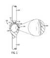
- FIG. 1shows a cross-sectional view of a stabilizing element having a ball-and-socket type joint.
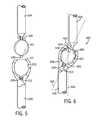
- FIG. 2shows a cross-sectional posterior view of the two segments of a stabilizing element that come together to form a pivoting joint, wherein the stabilizing element is a stabilizing rod.
- FIG. 3shows a posterior cross-sectional view of the two segments in FIG. 2 connected to form a pivoting joint.
- FIG. 4shows a posterior view of the stabilizing element of FIG. 3 .
- FIG. 5shows a lateral cross-sectional view of the stabilizing element of FIG. 3 .
- FIG. 6shows a stabilizing element having a tilted pivoting joint.
- FIG. 7shows a stabilization system implanted in a spine, including the stabilizing element of FIGS. 2-5 and a disc prosthesis.
- FIG. 8shows a posterior view of a spinal stabilization system implanted in a spine, including two stabilizing elements of the type shown in FIGS. 2-5 and an articulating transverse connector.
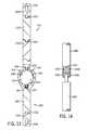
- FIG. 9shows a lateral view of a stabilizing element having damped flexion, extension, and translational motions.
- FIG. 10shows a posterior view of the stabilizing element of FIG. 9 .
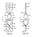
- FIG. 11shows a cross-sectional posterior view of the two segments of the stabilizing element that come together to form a pivoting joint, wherein the stabilizing element is a stabilizing plate.
- FIG. 12shows a lateral cross-sectional view of the stabilizing element of FIG. 11 .
- FIG. 13shows a cross-sectional posterior view of the stabilizing element wherein the two segments that connect to form a pivoting joint are each composed of multiple sections.
- FIG. 14shows a stabilizing element composed of two segments connected together by a compressible joint, wherein the stabilizing element is a stabilizing rod.
- FIG. 15shows a cross section of a polyaxial pedicle screw that may be used as a connector.
- FIG. 16shows a cross section of a polyaxial hook that may be used as a connector.
- FIG. 17shows a posterior view of a spinal stabilization system that includes two dynamic stabilizing elements.
- FIG. 18shows a cross-sectional lateral view of the spinal stabilization system of FIG. 17 , including a disc prosthesis.
- FIG. 19shows a dynamic stabilizing element composed of a spring protected by a housing.
- FIG. 20shows a spinal stabilization system that includes a disc prosthesis and two spinal stabilizing elements of the type shown in FIG. 19 attached to the anterior of a spinal column.
- FIG. 21shows a spinal stabilization system that includes a disc prosthesis and two spinal stabilizing elements of the type shown in FIG. 19 attached to opposite sides of the spinous processes.
- FIG. 22shows a spinal stabilization system that includes a disc prosthesis and two spinal stabilizing elements of the type shown in FIG. 19 attached across a pair of facet joints.
- Non-rigid spinal stabilizing elements and spinal stabilization systemswhich combine the spinal stabilizing elements with disc prostheses or disc nucleus replacements are provided herein.
- the spinal stabilization systemsare designed to retain or simulate at least some of the physiological intervertebral mobility of the spine by distributing the stress and mobility functions between one or more disc prostheses or disc nucleus replacements and one or more stabilizing elements.
- the stabilizing elements and stabilization systems provided hereinare useful for stabilizing the cervical, thoracic and lumbar regions of the spine, may be combined with one or more prosthetic vertebral bodies and may be used to preserve the natural mobility of a facet joint in patients with facet disease or patients who have had a prior destabilizing procedure, such as a facetectomy or a laminectomy.
- a first aspect of the inventionprovides a spinal stabilization system that includes the following basic elements: 1) a segmented stabilizing element composed of at least two segments; 2) a joint connecting the at least two segments of the stabilizing element; 3) a first connector adapted to connect the stabilizing element with a first vertebra in a spinal column; 4) a second connector adapted to connect the stabilizing element to a second vertebra in the spinal column; and 5) a disc prosthesis or disc nucleus replacement adapted to be inserted into an intervertebral space between two adjacent vertebra in the spinal column.
- the stabilizing elements of the spinal stabilization systemare designed to stabilize the spine by relieving some of the stress on an intervertebral disc prosthesis and to preserve at least some of the natural motion of one or more facet joints.
- the stabilizing elementsare a trans-vertebral stabilizing element. As such, the stabilizing elements span two or more vertebra in the spine and are located outside of the intervertebral spaces in the spinal column.
- the stabilizing elementswill typically be located at the posterior of the spine, but other placements including lateral and anterior placements are also possible.
- the stabilizing elementsmay be implanted by an open procedure, endoscopically or laprascopically.
- the spinal stabilization systemsmay include a single stabilizing element or two or more stabilizing elements.
- stabilizing elementWhen only a single stabilizing element is included, that stabilizing element is generally disposed posteriorly to one side of the spinous processes.
- stabilizing elementsWhen two stabilizing elements are included in the system, they are typically disposed in a spaced apart, substantially parallel arrangement wherein one of the stabilizing elements is placed on either side of the spinous processes.
- the elementsIn spinal stabilization systems that include two or more stabilizing elements, the elements optionally may be connected together through a transverse connector. Like the stabilizing elements, the transverse connectors may be composed of two or more segments connected together by a joint, typically a pivoting joint.
- the stabilizing elementsare typically rods or plates having a long dimension that runs along the long dimension of the spine when the stabilizing element is implanted in a patient.
- Spinal stabilizing rods and plateshave been described in the literature. These include, but are not limited to, the rods described in U.S. Pat. Nos. 6,554,831 and 4,743,260, the disclosures of which are incorporated herein by reference. Also included are the plates described in published U.S. Patent Application No. 2001/0037111 and U.S. Pat. No. 5,352,224, the disclosures of which are incorporated herein by reference. These rods and plates may be adapted for use as stabilizing elements in the present invention by inserting one or more connecting joints along their lengths.
- Each segment of the stabilizing elementmay be composed of a single integrally formed unit.
- one or more of the segmentsmay be sectional, that is, composed of a plurality of interlocking sections.
- the segments of a stabilizing rodmay be divided into sections that screw together end to end. This design allows the length of a segment to be tailored to fit a particular patient or a particular placement of the stabilizing elements along a spine.
- this designmakes it possible to easily switch out the sections that form the joint for rigid sections. This may be a desirable option, for example, when a disc prosthesis is exchanged for or converted into a fusion.
- the segmentsmay be adapted to be inserted into pre-existing stabilizing devices.
- the at least two segments of the stabilizing elementare connected by a joint.
- the jointserves at least two purposes.
- the jointserves to fasten the two segments of the stabilizing element together, and second, the joint provides for at least one degree of motion between the two segments.
- the jointmay be designed to provide or accommodate spinal flexion and extension and/or a lateral bending motion.
- a joint that provides or accommodates a flexion and extension and/or a lateral bending motionis referred to as a pivoting joint.
- the jointmay provide, accommodate, or damp spinal compression/expansion type motion.
- a joint that provides, accommodates, or damps a spinal compression/expansion motionis referred to as a compressible joint.
- the jointmay provide or accommodate a combination of the abovementioned motions.
- Suitable pivoting jointsinclude ball-and-socket type joints and joints based on a ball-and-socket type mechanism (i.e., joints including complimentary concave and convex surfaces).
- Spinal stabilizing elements including pivoting joints for use in combination with bone fusionshave been proposed. These spinal stabilizing elements may be used in combination with one or more intervertebral disc prostheses or one or more disc nucleus replacements to provide a spinal stabilization system in accordance with the present invention.
- a jointed intervertebral link devicethat may be used as a stabilizing element in the spinal stabilization systems provided herein is described in U.S. Pat. No. 6,241,730, the entire disclosure of which is incorporated herein by reference.
- the pivoting joint of the '730 patentincludes a socket extending into the proximal end of a first segment and a pin extending outwardly from the proximal end of a second segment, the pin having a distal end and an outwardly extending radial collar.
- a first damping elementis disposed around the pin above the collar and a second damping element is disposed around the pin below the collar. The pin and the first and second damping elements extend into the socket to form a joint that allows for multidirectional pivoting of the pin in the socket.
- FIG. 4Another suitable ball-and-socket joint design is described in reference to a jointed cross-link for an implantable spinal apparatus in U.S. Pat. No. 6,554,831 (see, e.g., FIG. 4 ), the entire disclosure of which is incorporated herein by reference.
- This jointis based on a ball-and-socket mechanism wherein a first segment has a proximal end defining a socket for receiving a ball integrally formed at the proximal end of a second segment. Together, the ball-and-socket provide a pivoting joint that connects the two segments.
- This type of jointmay be used as a pivoting joint in a transverse connector.
- Other illustrative joint designsare shown in FIGS. 2-13 , discussed in greater detail below.
- Connectorsare used to attach the stabilizing elements along the spinal column.
- the connectorsmay include any suitable connecting means capable of securing a stabilizing element to a vertebra. Suitable connectors include, but are not limited to, pedicle screws, hooks, and lateral mass screws.
- the connectorswill typically include a shaft, such as a rod, hook, nail or threaded screw shaft, that is adapted to penetrate or anchor to a bone and a securing portion adapted to secure the stabilizing element.
- the connectormay be a bone screw having a coarse thread on one end for threading into a bone and a machine thread on the opposing end for screwing into a matching tapped bore in a stabilizing element.
- the connectormay itself include multiple elements.
- the connectormay include a screw or hook secured to a rod clamp for connecting a stabilizing rod to a bone.
- the connectorsinclude polyaxial screws or hooks. Such screws or hooks allow for the accommodation of differing orientations and positioning between screws implanted in a series and may provide one or more degrees of motion between the connectors and the stabilizing elements to which they are attached.
- Suitable polyaxial pedicle screws and hooks for use as connectors in the spinal stabilization systems provided hereinare disclosed in U.S. Pat. Nos. 5,591,166, 5,628,740, and 6,626,908 the entire disclosures of which are incorporated herein by reference.
- the polyaxial pedicle screws disclosed in U.S. Pat. Nos. 5,591,166 and 5,628,740may be used without being locked into a fixed orientation such that the stabilizing elements retain a relative motion with respect to the shaft of the connector.
- the connectorsdesirably, but not necessarily, provide a rotatably adjustable connection to the stabilizing elements.
- a rotatably adjustable connectionrefers to a connection that allows the stabilizing elements, or individual segments thereof, to be rotated about their longitudinal axes before, during or after implantation of the spinal stabilization systems in order to allow the surgeon to optimize the orientation of the joint relative to the patient's spine.
- the connectorsmay include a locking mechanism adapted to lock-in the orientation, preventing further rotation once the orientation of the stabilizing element has been optimized.
- the pedicle screws described in U.S. Pat. Nos. 5,591,166 and 5,628,740,would be capable of serving this function.
- the stabilizing elementis a rod and the connector is a screw including a threaded shaft and a head having a lateral (i.e., perpendicular to the long axis of the shaft) bore extending therethrough.
- the diameter of the rodis small enough to allow the rod to pass through the bore and rotate therein.
- the connectorsmay be used to connect the stabilizing elements to adjacent or non-adjacent vertebrae in a spinal column.
- the connectorsare desirably, but not necessarily, attached to same vertebrae between which the disc prosthesis or disc nucleus replacement is disposed or to a prosthetic vertebral body or bodies.
- the connectorsmay be associated with pre-existing stabilizing devices, such that the stabilizing elements provided herein may be incorporated into or replace components of such devices.
- the stabilizing elementsare used in conjunction with at least one disc prosthesis or at least one disc nucleus replacement.
- the prosthesis or replacementis contained within an intervertebral space that is spanned by one or more stabilizing elements.
- a variety of intervertebral disc prosthesesmay be used in conjunction with the spinal stabilization elements provided herein. Many such disc prostheses have been proposed.
- the disc prosthesismay include a mechanical damping element, such as a spring, disposed between an inferior base plate adapted to be attached to an inferior vertebra, and a superior base plate adapted to be attached to a superior vertebra.
- the disc prosthesismay include a rubber, gel, or polymeric insert disposed between an inferior and a superior base plate.
- the disc prosthesismay be based on a ball-and-socket mechanism wherein one or more pairs of complementary concave and convex surfaces come together to form a joint.
- Suitable disc prosthesesthat may be used in the spinal stabilization systems provided herein include, but are not limited to, those described in U.S. Pat. Nos. 5,556,431; 5,401,269; 5,314,477; 6,368,350; 6,146,421; 6,139,579; and 5,562,738, the entire disclosures of which are incorporated herein by reference.
- Other suitable disc prosthesesare described in U.S. patent application Ser. No. 10/675,573, filed Sep. 30, 2003, the entire disclosure of which is incorporated herein by reference.
- the stabilizing elementsmay also be used with an artificial disc nucleus, such as a hydrogel-based nucleus replacement.
- the spinal stabilizing elements and spinal stabilization systems provided hereinmay span a single intervertebral space between two adjacent vertebra, or may span multiple intervertebral spaces, and possibly multiple disc prostheses and/or disc nucleus replacements, along a patient's spine.
- the spinal stabilization systems provided hereinmay also optionally include one or more prosthetic vertebral bodies spanned by one or more stabilizing elements.
- Suitable prosthetic vertebral bodies for incorporation into the spinal stabilization systems provided hereinhave been described in the literature. These include, but are not limited to, the prosthetic vertebral bodies described in U.S. Pat. Nos. 4,932,975; 5,306,310; 5,147,404; 5,989,290; and 6,001,130, the entire disclosures of which are incorporated herein by reference.
- Another suitable vertebral prosthesis that may be used with the spinal stabilization systems provided hereinis described in U.S. patent application Ser. No. 10/675,573, filed Sep. 30, 2003.
- the connectorsmay connect the stabilizing elements to the prosthetic vertebral body or to a vertebra.
- the phrases “connected to a vertebra” or “adapted to be connected to a vertebra”refer to connections to natural and artificial vertebrae.
- FIGS. 1-13show examples of pivoting joints that may be used to connect the first and second segments of a stabilizing element in the spinal stabilization systems provided herein.
- a rodis used as an illustrative stabilizing element.
- a plateis used as an illustrative stabilizing element.
- the terms “longitudinal” and “proximal”are used as relative terms.
- the term “longitudinal”is used to refer to the direction running lengthwise along the long dimension of a stabilizing element.
- proximalis used to refer to the location nearer to a joint.
- FIG. 1shows a ball-and-socket type joint 100 .
- the joint depicted in FIG. 1includes a first segment 102 having a generally spherical socket 106 extending into the proximal end thereof.
- the stabilizing element 100further includes a second segment 104 having a ball 108 disposed on the proximal end thereof.
- the second segment 104 and the ball 108are desirably, but not necessarily, integrally formed as one piece separated by a neck 110 .
- the ball 108 and socket 106fit together to provide a rotating joint.
- the sidewalls of the spherical socketshould extend upwardly beyond the maximum diameter of the ball in order to prevent the ball from becoming dislodged from the socket.
- the socketis desirably characterized by a flat strip 109 extending laterally around its midsection in order to allow for translation in the longitudinal direction.
- the second segment 104may optionally include a spring disposed around its neck in order to provide damping or restriction of translational, flexion, extension or lateral bending motions.
- the pivoting jointmay be formed by press fitting the ball into the socket.
- diametrically opposed longitudinal slitsmay be formed in the walls of the socket to provide the socket with a certain degree of flexibility, thus enabling the ball to slide more easily into the socket.
- the neck 110 of the second segment 104provides a certain amount of clearance between the first and second segments of the stabilizing element.
- the amount of clearance provided by the neck 110can influence how far the two segments may pivot before coming into abutment and preventing further pivoting motion.
- the clearance provided by the neck 110need not be uniform on all sides of the stabilizing element 100 .
- the shape of the circumference of the neck 110 or the shape of the upper surface 111 of the second segment 102may be designed to allow pivoting in some directions, but not in others.
- the stabilizing elementmay be designed to accommodate flexion and extension to a certain degree and lateral bending to a lesser degree.
- FIGS. 2-6depict an alternative embodiment of a pivoting joint that may be used to connect the two segments of the stabilizing element in a spinal stabilization system.
- FIG. 3shows a cross-sectional front view of the stabilizing element.
- the “front” viewmay correspond to an anterior, lateral or posterior view, depending on the intended orientation of the stabilizing element in the patent's spine.
- the front view in FIG. 3may be considered to be a posterior view, such that the plane extending perpendicularly into plane of the figure and bisecting the stabilizing element may be referred to as the “sagittal” plane and the plane lying in the plane of the figure and bisecting the stabilizing element may be referred to as the “lateral” plane.
- the stabilizing elementincludes a first segment 202 having a socket 205 extending into the proximal end thereof.
- This socket 205is defined by two opposing concave surfaces 206 , 208 separated by a gap 210 .
- the opposing concave surfacesdesirably include a flat strip 221 running laterally through the apex of their concavity.
- the socket shown in FIG. 2is further defined by a lower housing 212 centered on the longitudinal axis 214 of the stabilizing element and opening into the gap 210 .
- the stabilizing elementfurther includes a second segment 204 having an insert 215 disposed on its proximal end.
- the insertis characterized by two opposing convex surfaces 216 , 218 and is desirably, but not necessarily, integrally formed on the proximal end of the second segment 204 .
- the insertis disc-shaped, that is, it is wider in one dimension than the other. This design is advantageous because it limits the rotation of the joint about its longitudinal axis 214 .
- the outermost end of the insert 215desirably includes a flat extension 220 , while the opposing end forms a neck 222 in the second segment 204 .
- FIG. 3shows a pivoting joint formed by fitting the insert 215 into the socket 205 to connect the first segment 202 and the second segment 204 of the stabilizing element.
- This designallows the joint to pivot to a greater degree in the sagittal plane than in the lateral plane.
- the extent to which the joint may pivot in the sagittal planewill be determined, at least in part, by the clearance between the upper surface 211 of the first segment 202 and the shaft 213 of the second segment 204 provided by the neck 222 in the second segment.
- the extent to which the joint may pivotmay be increased by cutting a groove 400 into the proximal end of the first segment 202 .
- the flat extension 220 on the outmost end of the socket 205may extend into the socket housing 212 in order to accommodate longitudinal translation of one segment with respect to the other.
- a spring 300may be inserted into the housing 212 of the socket 215 in order to damp axial loading on the joint.
- a side view of the stabilizing element of FIG. 3is shown in FIG. 5 .
- the sockets extending into the proximal ends of the segmentsmay be characterized by a central axis, which is the axis running through the center of the opening of the socket at the outermost end of the segment.
- the pivoting jointpivots about a central axis that coincides with a longitudinal axis 214 of the stabilizing element.
- the stabilizing element 600includes a first segment 602 having a socket extending into its proximal end.
- This socketis defined in part by two opposing concave surfaces 606 , 608 separated by a gap.
- the stabilizing element 600further includes a second segment 604 having an insert 615 disposed on its proximal end.
- the insertis characterized by two opposing convex surfaces 616 , 618 .
- the joint shown in FIG. 6pivots about a central axis 622 that is not coincident with or parallel to the longitudinal axis 626 of the stabilizing element. Rather, the joint of FIG. 6 pivots about an axis 622 that forms an angle 624 with the longitudinal axis 626 of the stabilizing element.
- This designis advantageous because it allows a surgeon to optimize the orientation of the joint relative to the spinal column by rotating the first and second segments of the stabilizing element. In this manner, the pivoting joint may be properly aligned with the natural facet plane of each individual patient.
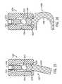
- FIG. 7shows a cross-sectional, lateral view of a spinal stabilization system that includes the spinal stabilizing element of FIGS. 2-5 in combination with an intervertebral disc prosthesis.
- the spinal stabilizing elementis connected across a first vertebra 702 and a second vertebra 704 to one side of the spinal processes (shown in dotted lines) at the posterior of the spine.
- the stabilizing elementis connected to the vertebrae using pedicle screws 706 , 708 .
- the pedicle screwseach include a screw head 710 , 712 having a lateral bore extending therethrough.
- the first and second segments of the stabilizing elementextend through the lateral bores in the first and second pedicle screw heads respectively.
- first and second segmentsmay be fixed to the pedicle screws by set screws 714 , 716 that screw through the screw heads 710 , 712 and press against or screw into or through the first and second segments of the stabilizing element.
- set screws 714 , 716that screw through the screw heads 710 , 712 and press against or screw into or through the first and second segments of the stabilizing element.
- many other connectors and connector configurationsmay be used to attach the segments to the vertebrae.
- the intervertebral disc prosthesis of the spinal stabilization system of FIG. 7includes an inferior base plate 722 adapted to be connected to the inferior vertebra 704 and a superior base plate 720 adapted to be connected to the superior vertebra 702 .
- the inferior base plateis characterized by an upwardly-facing concave surface which faces an oppositely disposed concave surface of the superior base plate 720 .
- the disc prosthesisfurther includes a disc insert 724 sandwiched between the superior and inferior base plates 720 , 722 .
- the disc insert 724is characterized by two opposing convex surfaces which complement the concave surfaces of the superior and inferior base plates 720 , 722 in order to provide one or more degrees of motion between the superior and inferior vertebrae 702 , 704 .
- a more detailed description of the disc insertis provided in U.S. patent application Ser. No. 10/675,573.
- FIG. 8shows a posterior view of the spinal stabilization system of FIG. 7 .
- the spinal stabilization systemincludes two spinal stabilization elements disposed on opposite sides of the spinous processes.
- the second segment 204 of the first stabilizing element and the second segment 804 of the second stabilizing elementare connected by a transverse connector 806 which limits the ability of the two stabilizing elements to move independently with respect to each other.
- the transverse connectormay itself include a first and a second segment 808 , 810 connected by a joint 812 , such as the ball-and-socket type joint shown in FIG. 1 .
- FIGS. 9 and 10show an alternative embodiment for a stabilizing element.
- the stabilizing elementincludes a first segment 902 having one or more tabs 906 , 908 extending upwardly and outwardly from its proximal end. Each of the tabs defines an internal window 907 .
- the first segmentalso includes a socket of the type shown in FIG. 2 extending into its proximal end.
- the stabilizing elementfurther includes a second segment 904 having one or more arms 910 , 912 extending downwardly and outwardly from its proximal end.
- the second segmentalso includes an insert of the type shown in FIG. 2 disposed on its proximal end.
- the arms 910 , 912 of the second segmentfit through the windows 907 in the tabs 906 , 908 of the first segment 902 .
- a first spring 914is disposed around the neck of the second segment to provide for damping of axial loading on the joint.
- a second and a third spring 916 , 918are disposed around the arms 910 , 912 of the second segment 904 in order to provide a damping or restriction of the flexion and extension or lateral motions of the joint.
- the dimensions of the window 907is desirably greater than the dimensions of the arm 910 to allow for a certain degree of translation and rotation of the arm 910 within the window 907 .
- FIGS. 11 and 12depict an embodiment of a pivoting joint that may be used to connect two segments of the stabilizing element in a spinal stabilization system, wherein the stabilizing element is a stabilizing plate.
- FIG. 11shows a cross-sectional front view of the stabilizing element.
- the plateincludes a first segment 1102 having a socket 1105 extending into the proximal end thereof. As best shown in FIG. 12 , the proximal end of the plate is expanded in order to accommodate the socket 1105 .
- This socket 1105is defined by two opposing concave surfaces 1106 , 1108 separated by a gap 1110 .
- the socketis further defined by a lower housing 1112 centered on the longitudinal axis of the stabilizing plate and opening into the gap 1110 .
- the stabilizing platefurther includes a second segment 1104 having an insert 1115 on its proximal end.
- the insertis characterized by two opposing convex surfaces 1116 , 1118 and is desirably, but not necessarily, integrally formed on the proximal end of the second segment 1104 .
- the insertis disc-shaped, that is, it is wider in one dimension than the other. This design is advantageous because it limits the rotation of the joint about its longitudinal axis.
- the outermost end of the insert 1115desirably includes a flat extension 1120 while the opposing end forms a neck 1122 in the second segment 1104 .
- the opposing concave surfaces 1106 , 1108 of the first segment 1102desirably include a flat strip running laterally through the apex of their concavity. This flat strip allows a certain degree of longitudinal translation between the socket and the insert when the joint is connected.
- the two segments 1102 , 1104 of the stabilizing element depicted thereineach also include a slot 1122 , 1124 extending through that segment. These slots are adapted to accept connectors, such as bone screws, hooks or nails in order to attach the stabilizing element to a vertebra.
- FIG. 13shows an embodiment of the stabilizing element of FIG. 3 wherein each of the first and second segments 202 , 204 is composed of a plurality of interconnecting sections 1326 , 1327 , 1328 , 1329 , 1330 .
- the segmentsare connected end to end through a series of screw type connections 1332 , 1333 , 1334 .
- one section 1326 , 1328 of each segment 202 , 204includes a slot 1336 , 1337 extending therethrough for accepting a connector such as a bone screw, hook or nail for attaching the stabilizing element to a vertebra.
- This embodimentmakes it easy to adjust the length of the stabilizing element and to replace the joint sections 1327 , 1330 with a rigid rod section in order to convert the pivoting stabilizing element into a rigid stabilizing element.
- FIG. 14shows a cross-sectional view of a portion of a stabilizing element that includes a compressible joint rather than a pivoting joint.
- the stabilizing elementincludes a first segment 1402 and a second segment 1404 .
- the first segment 1402includes a piston 1406 extending outwardly from its proximal end.
- a housing 1408is defined in the proximal end of the second segment 1404 .
- the piston 1406extends into the housing 1408 and a damping element 1410 is disposed between the distal end 1412 of the piston and the ceiling 1414 of the housing.
- the damping element depicted in FIG. 14is a spring.
- any suitable damping elementmay be used provided that element is capable of damping the axial loading on the joint.
- Other suitable damping elementsinclude polymer or gel-based elastomeric bumpers.
- the use of a damping element in the housing 1408 of the second segment 1404eliminates the need for a damping fluid. This is advantageous because compressible joints that employ a damping fluid run the risk of leaking, causing an irritation, infection or toxicity in the patient.
- FIG. 15shows an embodiment of a polyaxial pedicle screw 1560 , of the type disclosed in U.S. Pat. No. 6,626,908, that may be used as a connector in the spinal stabilization systems provided herein.
- the polyaxial pedicle screw 1560comprises a pedicle screw 1562 , a housing 1564 , a saddle shaped element 1566 , a set screw 1568 , a set screw aperture 1570 , and a rod 1572 .
- the pedicle screwcomprises a screw stem 1574 and a screw head 1576 .
- the housing 1564has a through bore with a diameter at the top sufficient to allow the screw stem 1574 and the screw head 1576 of the pedicle screw 1562 through the housing.
- the through bore diameternarrows at the bottom of the housing 1564 sufficient to allow only the screw stem 1574 through the bottom of the housing 1564 .
- the saddle shaped element 1566extends across the width of the housing 1564 and can not be angularly displaced relative to the housing 1564 .
- the saddle shaped element 1566has a cylindrical shaped upper surface for engagement with the rod 1572 .
- the saddle shaped element 1566also has a spherical lower portion for engaging with the screw head 1576 that has a complementary spherical recess.
- the set screw 1568is screwed into the set screw aperture 1570 to clamp the rod 1572 in position relative to the housing 1564 .
- the engagement between the saddle shaped element 1566 and the screw head 1576allows the housing 1564 to pivot with respect to the fixed pedicle screw 1562 thereby allowing the rod 1572 to pivot relative to the attachment point.
- FIG. 16shows a polyaxial hook 1678 that is similar to the polyaxial pedicle screw 1560 of FIG. 15 except that the pedicle screw 1562 has been replaced with a hook 1680 for attaching to the vertebra.
- the hook 1680comprises a hook stem 1682 and a hook head 1684 .
- the hook head 1684similarly has a complementary spherical recess for engaging with the saddle shaped element 1566 and allowing the housing 1564 to pivot relative to the hook 1680 .
- a second aspect of the inventionprovides a spinal stabilization system that includes the following basic elements: 1) at least one dynamic stabilizing element; 2) a first connector adapted to connect the at least one dynamic stabilizing element to a first vertebrae in a spinal column; 3) a second connector adapted to connect the at least one dynamic stabilizing element to a second vertebra in the spinal column; and 4) a disc prosthesis or disc nucleus replacement adapted to be inserted into an intervertebral space between two adjacent vertebrae in the spinal column.
- the connectorsmay attach the stabilizing elements to the same vertebra between which the disc prosthesis or disc nucleus replacement is disposed, or to other vertebra in the spinal column.
- the dynamic stabilizing elementis the dynamic spinal orthosis disclosed in U.S. Pat. No. 5,672,175, the disclosure of which is incorporated herein by reference.
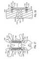
- FIGS. 17 and 18illustrate a spinal stabilization system that used two spinal stabilizing elements similar to those disclosed in the '174 patent.
- the spinal stabilization systemincludes two dynamic stabilizing elements, each composed of a flexible rod 1702 , 1704 .
- the flexible rodsare each attached to one vertebra in a manner that allows the rod to translate longitudinally with respect to that vertebra, where a “longitudinal” translation refers to a translation along the long axis of the spine.
- each rodis attached by a first connector 1706 , 1708 to a first vertebra 1710 and by a second connector 1712 , 1714 to a second vertebra 1716 .
- Each connectorincludes a shaft 1718 , 1720 (e.g., a nail, pin, hook or threaded screw shaft) that provides a connection to a bone or a prosthetic vertebral body and a securing portion 1722 , 1723 , 1724 , 1725 that provides a connection to the flexible rod.
- the first connector 1706 , 1708is adapted to provide a rigid attachment to the flexible rod 1702 , 1704 , that is, an attachment that prevents relative motion between the flexible rod and the shaft of the connector.
- the shaft 1718 of the first connectoris a threaded screw shaft adapted to penetrate into a bone 1710 and the rod securing portion is a screw head 1722 , 1724 (or nail head or hook head) having a bore 1726 extending therethrough.
- the flexible rod 1702 , 1704is inserted through the bore 1726 and locked into a fixed position by one or more transverse set screws 1728 , 1729 that screw against, into or through the rod 1702 , 1704 after it has been inserted into the bore.
- the shaft of the second connectormay also be a threaded screw shaft 1720 (or nail shaft or hook) adapted to penetrate into a bone 1716 and the rod securing portion includes a housing 1730 enclosing a coupling member that includes a sphere 1732 having a cylindrical bore 1734 for engagement with the flexible rod 1702 , 1704 .
- the coupling memberis capable of allowing translation of the flexible rod 1702 , 1704 along the axis of the bore.
- the coupling membermay also optionally allow rotation of the flexible rod about the axis of curvature, about an axis perpendicular to the frontal plane, or about an axis perpendicular to the sagittal plane. In the embodiment depicted in FIGS.
- the spinal stabilization systemfurther includes a spring 1740 , 1742 disposed around each flexible rod 1702 , 1704 to allow for axial damping.
- FIG. 18shows a cross-sectional lateral view of the spinal stabilization system taken through the plane of attachment.
- the springsmay be enclosed in a housing or sheathed in a tissue growth-resistant material in order to prevent tissue growth from interfering with their operation.
- the systemalso includes a disc prosthesis 1750 .
- the illustrative disc prosthesisincludes a superior base plate 1752 , an inferior base plate 1754 and a central elastomeric insert 1756 .
- the spinal stabilization systemincludes two dynamic stabilizing elements, wherein each dynamic stabilizing element is composed of a damping element and each damping element is a dynamic bias device as disclosed in U.S. Pat. No. 6,402,750, the disclosure of which is incorporated herein by reference.
- the two stabilizing elementsare disposed in a spaced-apart, substantially parallel relation, typically at the posterior of the spine, on opposite sides of the spinous processes.
- the damping elementsmay be springs, including coiled springs, leaf springs, articulated leaf springs, torsional springs, torsional leaf springs, or articulated torsional leaf springs.
- FIG. 19illustrates a simple damping element, of the type disclosed in the '750 patent, that may be used as a spinal stabilizing element.
- This stabilizing elementincludes a coiled spring 1902 connected to two wires 1904 , 1906 which are themselves connected to a first and a second bone screw 1908 , 1910 .
- the spring 1902is housed within a housing 1912 to prevent tissue growth from interfering with the spring 1902 .
- FIGS. 20-22show examples of possible attachment locations for the stabilizing elements of FIG. 19 .
- FIG. 20shows a first stabilizing element 2002 and a second stabilizing element 2003 attached to the anterior spinal column across a first vertebra 2004 and a second vertebra 2006 .
- the first stabilizing element 2002is attached to the first vertebra 2004 using a first connector 2010 and to the second vertebra 2004 using a second connector 2012 .
- the second stabilizing element 2003is attached to the first vertebra 2004 using third connector 2014 and to the second vertebra 2006 using fourth connector 2016 .
- FIG. 21 and FIG. 22show two additional possible attachment configurations for the first and second stabilizing elements 2002 , 2003 of FIG. 20 .
- the stabilizing elements 2002 , 2003are attached to the spinous processes 2100 of two adjacent vertebrae 2106 , 2108 , symmetrically about the sagittal plane and parallel to the axis of curvature.
- FIG. 22shows the two stabilizing elements 2002 , 2003 attached across the facet joints 2202 , 2204 of two adjacent vertebrae 2206 , 2208 .
- the components of the various stabilizing elements and stabilization systems provided hereinmay be constructed from biologically compatible materials. Many such materials are known. These include, but are not limited to, metals, such as titanium, titanium alloys, chrome cobalt or stainless steel. Other biocompatible materials include graphite and ceramics, such as hydroxapatites. Plastics may also be employed. Suitable plastics include polyethylene (e.g., ultrahigh molecular weight polyethylene) and polyether ester ketone.
Landscapes
- Health & Medical Sciences (AREA)
- Orthopedic Medicine & Surgery (AREA)
- Neurology (AREA)
- Life Sciences & Earth Sciences (AREA)
- Surgery (AREA)
- Engineering & Computer Science (AREA)
- Biomedical Technology (AREA)
- General Health & Medical Sciences (AREA)
- Veterinary Medicine (AREA)
- Heart & Thoracic Surgery (AREA)
- Public Health (AREA)
- Animal Behavior & Ethology (AREA)
- Molecular Biology (AREA)
- Medical Informatics (AREA)
- Nuclear Medicine, Radiotherapy & Molecular Imaging (AREA)
- Cardiology (AREA)
- Oral & Maxillofacial Surgery (AREA)
- Transplantation (AREA)
- Vascular Medicine (AREA)
- Prostheses (AREA)
- Surgical Instruments (AREA)
Abstract
Description
Claims (24)
Priority Applications (6)
| Application Number | Priority Date | Filing Date | Title |
|---|---|---|---|
| US10/722,119US7862586B2 (en) | 2003-11-25 | 2003-11-25 | Spinal stabilization systems |
| JP2006541692AJP2007537772A (en) | 2003-11-25 | 2004-11-23 | Spine stabilization system |
| EP04812086AEP1691732A4 (en) | 2003-11-25 | 2004-11-23 | Spinal stabilization systems |
| AU2004294954AAU2004294954B2 (en) | 2003-11-25 | 2004-11-23 | Spinal stabilization systems |
| PCT/US2004/039494WO2005053572A2 (en) | 2003-11-25 | 2004-11-23 | Spinal stabilization systems |
| US12/982,476US8486113B2 (en) | 2003-11-25 | 2010-12-30 | Spinal stabilization systems |
Applications Claiming Priority (1)
| Application Number | Priority Date | Filing Date | Title |
|---|---|---|---|
| US10/722,119US7862586B2 (en) | 2003-11-25 | 2003-11-25 | Spinal stabilization systems |
Related Child Applications (1)
| Application Number | Title | Priority Date | Filing Date |
|---|---|---|---|
| US12/982,476ContinuationUS8486113B2 (en) | 2003-11-25 | 2010-12-30 | Spinal stabilization systems |
Publications (2)
| Publication Number | Publication Date |
|---|---|
| US20050113927A1 US20050113927A1 (en) | 2005-05-26 |
| US7862586B2true US7862586B2 (en) | 2011-01-04 |
Family
ID=34591964
Family Applications (2)
| Application Number | Title | Priority Date | Filing Date |
|---|---|---|---|
| US10/722,119Active2029-07-04US7862586B2 (en) | 2003-11-25 | 2003-11-25 | Spinal stabilization systems |
| US12/982,476Expired - Fee RelatedUS8486113B2 (en) | 2003-11-25 | 2010-12-30 | Spinal stabilization systems |
Family Applications After (1)
| Application Number | Title | Priority Date | Filing Date |
|---|---|---|---|
| US12/982,476Expired - Fee RelatedUS8486113B2 (en) | 2003-11-25 | 2010-12-30 | Spinal stabilization systems |
Country Status (5)
| Country | Link |
|---|---|
| US (2) | US7862586B2 (en) |
| EP (1) | EP1691732A4 (en) |
| JP (1) | JP2007537772A (en) |
| AU (1) | AU2004294954B2 (en) |
| WO (1) | WO2005053572A2 (en) |
Cited By (115)
| Publication number | Priority date | Publication date | Assignee | Title |
|---|---|---|---|---|
| US20080177332A1 (en)* | 2003-12-15 | 2008-07-24 | Archus Orthopedics, Inc. | Polyaxial adjustment of facet joint prostheses |
| US20080287997A1 (en)* | 2004-10-20 | 2008-11-20 | Moti Altarac | Interspinous spacer |
| US20080294263A1 (en)* | 2004-10-20 | 2008-11-27 | Moti Altarac | Interspinous spacer |
| US20080300631A1 (en)* | 2007-05-31 | 2008-12-04 | Phusis | Device and unit for the posterior dynamic guidance of the spine and treatment system comprising such a device |
| US20080319550A1 (en)* | 2004-10-20 | 2008-12-25 | Moti Altarac | Interspinous spacer |
| US20090125030A1 (en)* | 2006-10-18 | 2009-05-14 | Shawn Tebbe | Dilator |
| US20090138055A1 (en)* | 2004-10-20 | 2009-05-28 | Moti Altarac | Spacer insertion instrument |
| US20090163955A1 (en)* | 2007-12-19 | 2009-06-25 | Missoum Moumene | Polymeric Pedicle Rods and Methods of Manufacturing |
| US20090182380A1 (en)* | 2008-01-16 | 2009-07-16 | Custom Spine, Inc. | Spring-loaded dynamic pedicle screw assembly |
| US20090222043A1 (en)* | 2004-10-20 | 2009-09-03 | Moti Altarac | Interspinous process spacer instrument system with deployment indicator |
| US20090326583A1 (en)* | 2008-06-25 | 2009-12-31 | Missoum Moumene | Posterior Dynamic Stabilization System With Flexible Ligament |
| US20090326584A1 (en)* | 2008-06-27 | 2009-12-31 | Michael Andrew Slivka | Spinal Dynamic Stabilization Rods Having Interior Bumpers |
| US20100030224A1 (en)* | 2008-02-26 | 2010-02-04 | Spartek Medical, Inc. | Surgical tool and method for connecting a dynamic bone anchor and dynamic vertical rod |
| US20100030271A1 (en)* | 2008-02-26 | 2010-02-04 | Spartek Medical, Inc. | Modular in-line deflection rod and bone anchor system and method for dynamic stabilization of the spine |
| US20100030267A1 (en)* | 2007-06-05 | 2010-02-04 | Spartek Medical, Inc. | Surgical tool and method for implantation of a dynamic bone anchor |
| US20100030270A1 (en)* | 2007-06-05 | 2010-02-04 | Spartek Medical, Inc. | Dynamic spinal rod assembly and method for dynamic stabilization of the spine |
| US20100030274A1 (en)* | 2007-06-05 | 2010-02-04 | Spartek Medical, Inc. | Dynamic spinal rod and method for dynamic stabilization of the spine |
| US20100030279A1 (en)* | 2008-02-26 | 2010-02-04 | Spartek Medical, Inc. | Load-sharing bone anchor having a deflectable post and axial spring and method for dynamic stabilization of the spine |
| US20100036426A1 (en)* | 2008-02-26 | 2010-02-11 | Spartek Medical, Inc. | Versatile offset polyaxial connector and method for dynamic stabilization of the spine |
| US20100036436A1 (en)* | 2008-02-26 | 2010-02-11 | Spartek Medical, Inc. | Load-sharing bone anchor having a durable compliant member and method for dynamic stabilization of the spine |
| US20100036437A1 (en)* | 2008-02-26 | 2010-02-11 | Spartek Medical, Inc. | Load-sharing bone anchor having a deflectable post with a compliant ring and method for stabilization of the spine |
| US20100036435A1 (en)* | 2008-02-26 | 2010-02-11 | Spartek Medical, Inc. | Load-sharing bone anchor having a deflectable post and method for dynamic stabilization of the spine |
| US20100036438A1 (en)* | 2008-02-26 | 2010-02-11 | Spartek Medical, Inc. | Load-sharing bone anchor having a deflectable post with a compliant ring and method for stabilization of the spine |
| US20100057139A1 (en)* | 2007-06-05 | 2010-03-04 | Spartek Medical, Inc. | Bone anchor for receiving a rod for stabilization and motion preservation spinal implantation system and method |
| US20100087880A1 (en)* | 2004-02-17 | 2010-04-08 | Facet Solutions, Inc. | Facet Joint Replacement Instruments and Methods |
| US20100145388A1 (en)* | 2008-12-03 | 2010-06-10 | Spartek Medical, Inc. | Low profile spinal prosthesis incorporating a bone anchor having a deflectable post and a compound spinal rod |
| US20100211107A1 (en)* | 2009-02-13 | 2010-08-19 | Muhanna Nabil L | Facet joint prosthetic replacement and method |
| US20100211104A1 (en)* | 2009-02-13 | 2010-08-19 | Missoum Moumene | Dual Spring Posterior Dynamic Stabilization Device With Elongation Limiting Elastomers |
| US20100262191A1 (en)* | 2009-04-13 | 2010-10-14 | Warsaw Orthopedic, Inc. | Systems and devices for dynamic stabilization of the spine |
| US20100331886A1 (en)* | 2009-06-25 | 2010-12-30 | Jonathan Fanger | Posterior Dynamic Stabilization Device Having A Mobile Anchor |
| US20110106160A1 (en)* | 2004-10-20 | 2011-05-05 | The Board Of Trustees Of The Leland Stanford Junior University | Systems and methods for posterior dynamic stabilization of the spine |
| US20110118783A1 (en)* | 2009-11-16 | 2011-05-19 | Spartek Medical, Inc. | Load-sharing bone anchor having a flexible post and method for dynamic stabilization of the spine |
| KR101046535B1 (en) | 2011-03-28 | 2011-07-05 | 주식회사 형근 | Rotary Motion Processing Equipment |
| US8021396B2 (en) | 2007-06-05 | 2011-09-20 | Spartek Medical, Inc. | Configurable dynamic spinal rod and method for dynamic stabilization of the spine |
| US20110238119A1 (en)* | 2010-03-24 | 2011-09-29 | Missoum Moumene | Composite Material Posterior Dynamic Stabilization Spring Rod |
| US8057515B2 (en) | 2008-02-26 | 2011-11-15 | Spartek Medical, Inc. | Load-sharing anchor having a deflectable post and centering spring and method for dynamic stabilization of the spine |
| US8097024B2 (en) | 2008-02-26 | 2012-01-17 | Spartek Medical, Inc. | Load-sharing bone anchor having a deflectable post and method for stabilization of the spine |
| US8114134B2 (en) | 2007-06-05 | 2012-02-14 | Spartek Medical, Inc. | Spinal prosthesis having a three bar linkage for motion preservation and dynamic stabilization of the spine |
| US8257397B2 (en) | 2009-12-02 | 2012-09-04 | Spartek Medical, Inc. | Low profile spinal prosthesis incorporating a bone anchor having a deflectable post and a compound spinal rod |
| US8292922B2 (en) | 2004-10-20 | 2012-10-23 | Vertiflex, Inc. | Interspinous spacer |
| US20130041469A1 (en)* | 2011-08-11 | 2013-02-14 | Jeff Phelps | Interbody axis cage |
| US20130090690A1 (en)* | 2011-10-06 | 2013-04-11 | David A. Walsh | Dynamic Rod Assembly |
| US8430916B1 (en) | 2012-02-07 | 2013-04-30 | Spartek Medical, Inc. | Spinal rod connectors, methods of use, and spinal prosthesis incorporating spinal rod connectors |
| US8518085B2 (en) | 2010-06-10 | 2013-08-27 | Spartek Medical, Inc. | Adaptive spinal rod and methods for stabilization of the spine |
| US8740948B2 (en) | 2009-12-15 | 2014-06-03 | Vertiflex, Inc. | Spinal spacer for cervical and other vertebra, and associated systems and methods |
| US8828058B2 (en) | 2008-11-11 | 2014-09-09 | Kspine, Inc. | Growth directed vertebral fixation system with distractible connector(s) and apical control |
| US8864828B2 (en) | 2004-10-20 | 2014-10-21 | Vertiflex, Inc. | Interspinous spacer |
| US8900271B2 (en) | 2004-10-20 | 2014-12-02 | The Board Of Trustees Of The Leland Stanford Junior University | Systems and methods for posterior dynamic stabilization of the spine |
| US8920472B2 (en) | 2011-11-16 | 2014-12-30 | Kspine, Inc. | Spinal correction and secondary stabilization |
| US9011491B2 (en) | 2004-08-03 | 2015-04-21 | K Spine, Inc. | Facet device and method |
| US9039742B2 (en) | 2004-10-20 | 2015-05-26 | The Board Of Trustees Of The Leland Stanford Junior University | Systems and methods for posterior dynamic stabilization of the spine |
| US9119680B2 (en) | 2004-10-20 | 2015-09-01 | Vertiflex, Inc. | Interspinous spacer |
| US9125692B2 (en) | 2004-10-20 | 2015-09-08 | The Board Of Trustees Of The Leland Stanford Junior University | Systems and methods for posterior dynamic stabilization of the spine |
| US9149306B2 (en) | 2011-06-21 | 2015-10-06 | Seaspine, Inc. | Spinous process device |
| US9155572B2 (en) | 2004-10-20 | 2015-10-13 | Vertiflex, Inc. | Minimally invasive tooling for delivery of interspinous spacer |
| US9161783B2 (en) | 2004-10-20 | 2015-10-20 | Vertiflex, Inc. | Interspinous spacer |
| US9168071B2 (en) | 2009-09-15 | 2015-10-27 | K2M, Inc. | Growth modulation system |
| US9173681B2 (en) | 2009-03-26 | 2015-11-03 | K2M, Inc. | Alignment system with longitudinal support features |
| US9211146B2 (en) | 2004-10-20 | 2015-12-15 | The Board Of Trustees Of The Leland Stanford Junior University | Systems and methods for posterior dynamic stabilization of the spine |
| US9283005B2 (en) | 2004-10-20 | 2016-03-15 | Vertiflex, Inc. | Systems and methods for posterior dynamic stabilization of the spine |
| US9314279B2 (en) | 2004-10-20 | 2016-04-19 | The Board Of Trustees Of The Leland Stanford Junior University | Systems and methods for posterior dynamic stabilization of the spine |
| US9333009B2 (en) | 2011-06-03 | 2016-05-10 | K2M, Inc. | Spinal correction system actuators |
| US9393055B2 (en) | 2004-10-20 | 2016-07-19 | Vertiflex, Inc. | Spacer insertion instrument |
| US9451987B2 (en) | 2011-11-16 | 2016-09-27 | K2M, Inc. | System and method for spinal correction |
| US9468469B2 (en) | 2011-11-16 | 2016-10-18 | K2M, Inc. | Transverse coupler adjuster spinal correction systems and methods |
| US9468471B2 (en) | 2013-09-17 | 2016-10-18 | K2M, Inc. | Transverse coupler adjuster spinal correction systems and methods |
| US9468468B2 (en) | 2011-11-16 | 2016-10-18 | K2M, Inc. | Transverse connector for spinal stabilization system |
| US9675303B2 (en) | 2013-03-15 | 2017-06-13 | Vertiflex, Inc. | Visualization systems, instruments and methods of using the same in spinal decompression procedures |
| US20170325847A1 (en)* | 2012-09-24 | 2017-11-16 | Refai Technologies, L.L.C. | Articulating spinal rod system |
| US9844398B2 (en) | 2012-05-11 | 2017-12-19 | Orthopediatrics Corporation | Surgical connectors and instrumentation |
| US10016220B2 (en) | 2011-11-01 | 2018-07-10 | Nuvasive Specialized Orthopedics, Inc. | Adjustable magnetic devices and methods of using same |
| US10039661B2 (en) | 2006-10-20 | 2018-08-07 | Nuvasive Specialized Orthopedics, Inc. | Adjustable implant and method of use |
| US10238427B2 (en) | 2015-02-19 | 2019-03-26 | Nuvasive Specialized Orthopedics, Inc. | Systems and methods for vertebral adjustment |
| WO2019079581A1 (en)* | 2017-10-20 | 2019-04-25 | Mayo Foundation For Medical Education And Research | Facet joint replacement devices |
| US10271885B2 (en) | 2014-12-26 | 2019-04-30 | Nuvasive Specialized Orthopedics, Inc. | Systems and methods for distraction |
| US10292738B2 (en) | 2004-10-20 | 2019-05-21 | The Board Of Trustees Of The Leland Stanford Junior University | Systems and methods for stabilizing the motion or adjusting the position of the spine |
| US10327818B2 (en) | 2012-06-18 | 2019-06-25 | Bruce Francis Hodgson | Method and apparatus for the treatment of scoliosis |
| US10349995B2 (en) | 2007-10-30 | 2019-07-16 | Nuvasive Specialized Orthopedics, Inc. | Skeletal manipulation method |
| US10405891B2 (en) | 2010-08-09 | 2019-09-10 | Nuvasive Specialized Orthopedics, Inc. | Maintenance feature in magnetic implant |
| US10478232B2 (en) | 2009-04-29 | 2019-11-19 | Nuvasive Specialized Orthopedics, Inc. | Interspinous process device and method |
| US10517643B2 (en) | 2009-02-23 | 2019-12-31 | Nuvasive Specialized Orthopedics, Inc. | Non-invasive adjustable distraction system |
| US10524772B2 (en) | 2014-05-07 | 2020-01-07 | Vertiflex, Inc. | Spinal nerve decompression systems, dilation systems, and methods of using the same |
| US10617453B2 (en) | 2015-10-16 | 2020-04-14 | Nuvasive Specialized Orthopedics, Inc. | Adjustable devices for treating arthritis of the knee |
| US10646262B2 (en) | 2011-02-14 | 2020-05-12 | Nuvasive Specialized Orthopedics, Inc. | System and method for altering rotational alignment of bone sections |
| US10660675B2 (en) | 2010-06-30 | 2020-05-26 | Nuvasive Specialized Orthopedics, Inc. | External adjustment device for distraction device |
| US10702311B2 (en) | 2011-11-16 | 2020-07-07 | K2M, Inc. | Spinal correction and secondary stabilization |
| US10729470B2 (en) | 2008-11-10 | 2020-08-04 | Nuvasive Specialized Orthopedics, Inc. | External adjustment device for distraction device |
| US10743794B2 (en) | 2011-10-04 | 2020-08-18 | Nuvasive Specialized Orthopedics, Inc. | Devices and methods for non-invasive implant length sensing |
| US10751094B2 (en) | 2013-10-10 | 2020-08-25 | Nuvasive Specialized Orthopedics, Inc. | Adjustable spinal implant |
| US10835290B2 (en) | 2015-12-10 | 2020-11-17 | Nuvasive Specialized Orthopedics, Inc. | External adjustment device for distraction device |
| US10918425B2 (en) | 2016-01-28 | 2021-02-16 | Nuvasive Specialized Orthopedics, Inc. | System and methods for bone transport |
| US11191579B2 (en) | 2012-10-29 | 2021-12-07 | Nuvasive Specialized Orthopedics, Inc. | Adjustable devices for treating arthritis of the knee |
| US11202707B2 (en) | 2008-03-25 | 2021-12-21 | Nuvasive Specialized Orthopedics, Inc. | Adjustable implant system |
| US11207110B2 (en) | 2009-09-04 | 2021-12-28 | Nuvasive Specialized Orthopedics, Inc. | Bone growth device and method |
| US11246694B2 (en) | 2014-04-28 | 2022-02-15 | Nuvasive Specialized Orthopedics, Inc. | System for informational magnetic feedback in adjustable implants |
| USRE49061E1 (en) | 2012-10-18 | 2022-05-10 | Nuvasive Specialized Orthopedics, Inc. | Intramedullary implants for replacing lost bone |
| US11357547B2 (en) | 2014-10-23 | 2022-06-14 | Nuvasive Specialized Orthopedics Inc. | Remotely adjustable interactive bone reshaping implant |
| US11357549B2 (en) | 2004-07-02 | 2022-06-14 | Nuvasive Specialized Orthopedics, Inc. | Expandable rod system to treat scoliosis and method of using the same |
| US11577097B2 (en) | 2019-02-07 | 2023-02-14 | Nuvasive Specialized Orthopedics, Inc. | Ultrasonic communication in medical devices |
| US11583318B2 (en) | 2018-12-21 | 2023-02-21 | Paradigm Spine, Llc | Modular spine stabilization system and associated instruments |
| US11589901B2 (en) | 2019-02-08 | 2023-02-28 | Nuvasive Specialized Orthopedics, Inc. | External adjustment device |
| US11696836B2 (en) | 2013-08-09 | 2023-07-11 | Nuvasive, Inc. | Lordotic expandable interbody implant |
| US11737787B1 (en) | 2021-05-27 | 2023-08-29 | Nuvasive, Inc. | Bone elongating devices and methods of use |
| US11766252B2 (en) | 2013-07-31 | 2023-09-26 | Nuvasive Specialized Orthopedics, Inc. | Noninvasively adjustable suture anchors |
| US11801187B2 (en) | 2016-02-10 | 2023-10-31 | Nuvasive Specialized Orthopedics, Inc. | Systems and methods for controlling multiple surgical variables |
| US20230346439A1 (en)* | 2021-10-22 | 2023-11-02 | Orthopedic Designs North America, Inc. | Self-contouring plate system for bone fractures with anti-rotation stop |
| US11806054B2 (en) | 2021-02-23 | 2023-11-07 | Nuvasive Specialized Orthopedics, Inc. | Adjustable implant, system and methods |
| US11839410B2 (en) | 2012-06-15 | 2023-12-12 | Nuvasive Inc. | Magnetic implants with improved anatomical compatibility |
| US11857226B2 (en) | 2013-03-08 | 2024-01-02 | Nuvasive Specialized Orthopedics | Systems and methods for ultrasonic detection of device distraction |
| US11925389B2 (en) | 2008-10-13 | 2024-03-12 | Nuvasive Specialized Orthopedics, Inc. | Spinal distraction system |
| US12023073B2 (en) | 2021-08-03 | 2024-07-02 | Nuvasive Specialized Orthopedics, Inc. | Adjustable implant |
| US12102542B2 (en) | 2022-02-15 | 2024-10-01 | Boston Scientific Neuromodulation Corporation | Interspinous spacer and methods and systems utilizing the interspinous spacer |
| US12213708B2 (en) | 2020-09-08 | 2025-02-04 | Nuvasive Specialized Orthopedics, Inc. | Remote control module for adjustable implants |
| US12390340B2 (en) | 2023-03-15 | 2025-08-19 | Boston Scientific Neuromodulation Corporation | Interspinous spacer with a range of deployment positions and methods and systems |
| US12433646B2 (en) | 2023-02-21 | 2025-10-07 | Boston Scientific Neuromodulation Corporation | Interspinous spacer with actuator locking arrangements and methods and systems |
Families Citing this family (321)
| Publication number | Priority date | Publication date | Assignee | Title |
|---|---|---|---|---|
| US7687462B2 (en)* | 1999-10-05 | 2010-03-30 | The Regents Of The University Of California | Composition for promoting cartilage formation or repair comprising a nell gene product and method of treating cartilage-related conditions using such composition |
| FR2812185B1 (en) | 2000-07-25 | 2003-02-28 | Spine Next Sa | SEMI-RIGID CONNECTION PIECE FOR RACHIS STABILIZATION |
| US7833250B2 (en) | 2004-11-10 | 2010-11-16 | Jackson Roger P | Polyaxial bone screw with helically wound capture connection |
| US20050080486A1 (en) | 2000-11-29 | 2005-04-14 | Fallin T. Wade | Facet joint replacement |
| US6579319B2 (en) | 2000-11-29 | 2003-06-17 | Medicinelodge, Inc. | Facet joint replacement |
| US6726689B2 (en) | 2002-09-06 | 2004-04-27 | Roger P. Jackson | Helical interlocking mating guide and advancement structure |
| US8377100B2 (en) | 2000-12-08 | 2013-02-19 | Roger P. Jackson | Closure for open-headed medical implant |
| US6419703B1 (en) | 2001-03-01 | 2002-07-16 | T. Wade Fallin | Prosthesis for the replacement of a posterior element of a vertebra |
| US7090698B2 (en)* | 2001-03-02 | 2006-08-15 | Facet Solutions | Method and apparatus for spine joint replacement |
| US7862587B2 (en) | 2004-02-27 | 2011-01-04 | Jackson Roger P | Dynamic stabilization assemblies, tool set and method |
| US10258382B2 (en) | 2007-01-18 | 2019-04-16 | Roger P. Jackson | Rod-cord dynamic connection assemblies with slidable bone anchor attachment members along the cord |
| US10729469B2 (en) | 2006-01-09 | 2020-08-04 | Roger P. Jackson | Flexible spinal stabilization assembly with spacer having off-axis core member |
| US8353932B2 (en) | 2005-09-30 | 2013-01-15 | Jackson Roger P | Polyaxial bone anchor assembly with one-piece closure, pressure insert and plastic elongate member |
| US8292926B2 (en) | 2005-09-30 | 2012-10-23 | Jackson Roger P | Dynamic stabilization connecting member with elastic core and outer sleeve |
| US20030114853A1 (en)* | 2001-10-12 | 2003-06-19 | Ian Burgess | Polyaxial cross connector |
| US6793678B2 (en) | 2002-06-27 | 2004-09-21 | Depuy Acromed, Inc. | Prosthetic intervertebral motion disc having dampening |
| US7955388B2 (en)* | 2006-11-01 | 2011-06-07 | Acumed Llc | Orthopedic connector system |
| US8282673B2 (en) | 2002-09-06 | 2012-10-09 | Jackson Roger P | Anti-splay medical implant closure with multi-surface removal aperture |
| US8257402B2 (en) | 2002-09-06 | 2012-09-04 | Jackson Roger P | Closure for rod receiving orthopedic implant having left handed thread removal |
| US8876868B2 (en) | 2002-09-06 | 2014-11-04 | Roger P. Jackson | Helical guide and advancement flange with radially loaded lip |
| WO2006052796A2 (en) | 2004-11-10 | 2006-05-18 | Jackson Roger P | Helical guide and advancement flange with break-off extensions |
| US8540753B2 (en) | 2003-04-09 | 2013-09-24 | Roger P. Jackson | Polyaxial bone screw with uploaded threaded shank and method of assembly and use |
| US7621918B2 (en) | 2004-11-23 | 2009-11-24 | Jackson Roger P | Spinal fixation tool set and method |
| US6716214B1 (en) | 2003-06-18 | 2004-04-06 | Roger P. Jackson | Polyaxial bone screw with spline capture connection |
| US7377923B2 (en) | 2003-05-22 | 2008-05-27 | Alphatec Spine, Inc. | Variable angle spinal screw assembly |
| US7766915B2 (en) | 2004-02-27 | 2010-08-03 | Jackson Roger P | Dynamic fixation assemblies with inner core and outer coil-like member |
| US8366753B2 (en) | 2003-06-18 | 2013-02-05 | Jackson Roger P | Polyaxial bone screw assembly with fixed retaining structure |
| US8257398B2 (en) | 2003-06-18 | 2012-09-04 | Jackson Roger P | Polyaxial bone screw with cam capture |
| US8092500B2 (en) | 2007-05-01 | 2012-01-10 | Jackson Roger P | Dynamic stabilization connecting member with floating core, compression spacer and over-mold |
| US7967850B2 (en) | 2003-06-18 | 2011-06-28 | Jackson Roger P | Polyaxial bone anchor with helical capture connection, insert and dual locking assembly |
| US7776067B2 (en) | 2005-05-27 | 2010-08-17 | Jackson Roger P | Polyaxial bone screw with shank articulation pressure insert and method |
| US8398682B2 (en) | 2003-06-18 | 2013-03-19 | Roger P. Jackson | Polyaxial bone screw assembly |
| US8926670B2 (en) | 2003-06-18 | 2015-01-06 | Roger P. Jackson | Polyaxial bone screw assembly |
| US8377102B2 (en) | 2003-06-18 | 2013-02-19 | Roger P. Jackson | Polyaxial bone anchor with spline capture connection and lower pressure insert |
| US8137386B2 (en) | 2003-08-28 | 2012-03-20 | Jackson Roger P | Polyaxial bone screw apparatus |
| US7753958B2 (en)* | 2003-08-05 | 2010-07-13 | Gordon Charles R | Expandable intervertebral implant |
| US7799082B2 (en) | 2003-08-05 | 2010-09-21 | Flexuspine, Inc. | Artificial functional spinal unit system and method for use |
| US7204853B2 (en)* | 2003-08-05 | 2007-04-17 | Flexuspine, Inc. | Artificial functional spinal unit assemblies |
| US7763052B2 (en)* | 2003-12-05 | 2010-07-27 | N Spine, Inc. | Method and apparatus for flexible fixation of a spine |
| US7137985B2 (en)* | 2003-09-24 | 2006-11-21 | N Spine, Inc. | Marking and guidance method and system for flexible fixation of a spine |
| US7815665B2 (en)* | 2003-09-24 | 2010-10-19 | N Spine, Inc. | Adjustable spinal stabilization system |
| US20050203513A1 (en)* | 2003-09-24 | 2005-09-15 | Tae-Ahn Jahng | Spinal stabilization device |
| US8979900B2 (en) | 2003-09-24 | 2015-03-17 | DePuy Synthes Products, LLC | Spinal stabilization device |
| US7255714B2 (en) | 2003-09-30 | 2007-08-14 | Michel H. Malek | Vertically adjustable intervertebral disc prosthesis |
| US7862586B2 (en) | 2003-11-25 | 2011-01-04 | Life Spine, Inc. | Spinal stabilization systems |
| US7588590B2 (en)* | 2003-12-10 | 2009-09-15 | Facet Solutions, Inc | Spinal facet implant with spherical implant apposition surface and bone bed and methods of use |
| US7179261B2 (en) | 2003-12-16 | 2007-02-20 | Depuy Spine, Inc. | Percutaneous access devices and bone anchor assemblies |
| US11419642B2 (en) | 2003-12-16 | 2022-08-23 | Medos International Sarl | Percutaneous access devices and bone anchor assemblies |
| US7527638B2 (en) | 2003-12-16 | 2009-05-05 | Depuy Spine, Inc. | Methods and devices for minimally invasive spinal fixation element placement |
| US7806914B2 (en)* | 2003-12-31 | 2010-10-05 | Spine Wave, Inc. | Dynamic spinal stabilization system |
| MXPA06007945A (en)* | 2004-01-13 | 2007-01-26 | Univ Toledo | Noninvasive birefringence compensated sensing polarimeter. |
| US8029548B2 (en) | 2008-05-05 | 2011-10-04 | Warsaw Orthopedic, Inc. | Flexible spinal stabilization element and system |
| US7993373B2 (en) | 2005-02-22 | 2011-08-09 | Hoy Robert W | Polyaxial orthopedic fastening apparatus |
| US8562649B2 (en) | 2004-02-17 | 2013-10-22 | Gmedelaware 2 Llc | System and method for multiple level facet joint arthroplasty and fusion |
| US8333789B2 (en) | 2007-01-10 | 2012-12-18 | Gmedelaware 2 Llc | Facet joint replacement |
| JP2007525274A (en) | 2004-02-27 | 2007-09-06 | ロジャー・ピー・ジャクソン | Orthopedic implant rod reduction instrument set and method |
| US11241261B2 (en) | 2005-09-30 | 2022-02-08 | Roger P Jackson | Apparatus and method for soft spinal stabilization using a tensionable cord and releasable end structure |
| US7892257B2 (en) | 2004-02-27 | 2011-02-22 | Custom Spine, Inc. | Spring loaded, load sharing polyaxial pedicle screw assembly and method |
| US8152810B2 (en) | 2004-11-23 | 2012-04-10 | Jackson Roger P | Spinal fixation tool set and method |
| US7160300B2 (en) | 2004-02-27 | 2007-01-09 | Jackson Roger P | Orthopedic implant rod reduction tool set and method |
| US7717939B2 (en) | 2004-03-31 | 2010-05-18 | Depuy Spine, Inc. | Rod attachment for head to head cross connector |
| US7645294B2 (en) | 2004-03-31 | 2010-01-12 | Depuy Spine, Inc. | Head-to-head connector spinal fixation system |
| US7811311B2 (en)* | 2004-12-30 | 2010-10-12 | Warsaw Orthopedic, Inc. | Screw with deployable interlaced dual rods |
| US7789899B2 (en)* | 2004-12-30 | 2010-09-07 | Warsaw Orthopedic, Inc. | Bone anchorage screw with built-in hinged plate |
| US7618418B2 (en)* | 2004-04-16 | 2009-11-17 | Kyphon Sarl | Plate system for minimally invasive support of the spine |
| US7648520B2 (en)* | 2004-04-16 | 2010-01-19 | Kyphon Sarl | Pedicle screw assembly |
| US7524323B2 (en)* | 2004-04-16 | 2009-04-28 | Kyphon Sarl | Subcutaneous support |
| US7766941B2 (en)* | 2004-05-14 | 2010-08-03 | Paul Kamaljit S | Spinal support, stabilization |
| US7507242B2 (en) | 2004-06-02 | 2009-03-24 | Facet Solutions | Surgical measurement and resection framework |
| US7758581B2 (en) | 2005-03-28 | 2010-07-20 | Facet Solutions, Inc. | Polyaxial reaming apparatus and method |
| US7931675B2 (en)* | 2004-06-23 | 2011-04-26 | Yale University | Dynamic stabilization device including overhanging stabilizing member |
| US8021428B2 (en)* | 2004-06-30 | 2011-09-20 | Depuy Spine, Inc. | Ceramic disc prosthesis |
| US7351261B2 (en)* | 2004-06-30 | 2008-04-01 | Depuy Spine, Inc. | Multi-joint implant |
| US7261738B2 (en) | 2004-06-30 | 2007-08-28 | Depuy Spine, Inc. | C-shaped disc prosthesis |
| US7854752B2 (en) | 2004-08-09 | 2010-12-21 | Theken Spine, Llc | System and method for dynamic skeletal stabilization |
| AU2005277363A1 (en)* | 2004-08-18 | 2006-03-02 | Fsi Acquisition Sub, Llc | Adjacent level facet arthroplasty devices, spine stabilization systems, and methods |
| US7717938B2 (en) | 2004-08-27 | 2010-05-18 | Depuy Spine, Inc. | Dual rod cross connectors and inserter tools |
| US7651502B2 (en) | 2004-09-24 | 2010-01-26 | Jackson Roger P | Spinal fixation tool set and method for rod reduction and fastener insertion |
| US8092496B2 (en)* | 2004-09-30 | 2012-01-10 | Depuy Spine, Inc. | Methods and devices for posterior stabilization |
| US20060084976A1 (en)* | 2004-09-30 | 2006-04-20 | Depuy Spine, Inc. | Posterior stabilization systems and methods |
| US7896906B2 (en)* | 2004-12-30 | 2011-03-01 | Depuy Spine, Inc. | Artificial facet joint |
| US7766940B2 (en) | 2004-12-30 | 2010-08-03 | Depuy Spine, Inc. | Posterior stabilization system |
| DE102004048938B4 (en)* | 2004-10-07 | 2015-04-02 | Synthes Gmbh | Device for the dynamic stabilization of vertebral bodies |
| US8226690B2 (en)* | 2005-07-22 | 2012-07-24 | The Board Of Trustees Of The Leland Stanford Junior University | Systems and methods for stabilization of bone structures |
| US7935134B2 (en)* | 2004-10-20 | 2011-05-03 | Exactech, Inc. | Systems and methods for stabilization of bone structures |
| US8162985B2 (en) | 2004-10-20 | 2012-04-24 | The Board Of Trustees Of The Leland Stanford Junior University | Systems and methods for posterior dynamic stabilization of the spine |
| US8025680B2 (en)* | 2004-10-20 | 2011-09-27 | Exactech, Inc. | Systems and methods for posterior dynamic stabilization of the spine |
| US8012207B2 (en) | 2004-10-20 | 2011-09-06 | Vertiflex, Inc. | Systems and methods for posterior dynamic stabilization of the spine |
| US8267969B2 (en) | 2004-10-20 | 2012-09-18 | Exactech, Inc. | Screw systems and methods for use in stabilization of bone structures |
| AU2005302633A1 (en)* | 2004-10-28 | 2006-05-11 | Axial Biotech, Inc. | Apparatus and method for concave scoliosis expansion |
| US8926672B2 (en) | 2004-11-10 | 2015-01-06 | Roger P. Jackson | Splay control closure for open bone anchor |
| WO2006057837A1 (en) | 2004-11-23 | 2006-06-01 | Jackson Roger P | Spinal fixation tool attachment structure |
| US8308782B2 (en) | 2004-11-23 | 2012-11-13 | Jackson Roger P | Bone anchors with longitudinal connecting member engaging inserts and closures for fixation and optional angulation |
| US8444681B2 (en) | 2009-06-15 | 2013-05-21 | Roger P. Jackson | Polyaxial bone anchor with pop-on shank, friction fit retainer and winged insert |
| US9168069B2 (en) | 2009-06-15 | 2015-10-27 | Roger P. Jackson | Polyaxial bone anchor with pop-on shank and winged insert with lower skirt for engaging a friction fit retainer |
| US9980753B2 (en) | 2009-06-15 | 2018-05-29 | Roger P Jackson | pivotal anchor with snap-in-place insert having rotation blocking extensions |
| US7875065B2 (en) | 2004-11-23 | 2011-01-25 | Jackson Roger P | Polyaxial bone screw with multi-part shank retainer and pressure insert |
| US9216041B2 (en) | 2009-06-15 | 2015-12-22 | Roger P. Jackson | Spinal connecting members with tensioned cords and rigid sleeves for engaging compression inserts |
| WO2006058221A2 (en) | 2004-11-24 | 2006-06-01 | Abdou Samy M | Devices and methods for inter-vertebral orthopedic device placement |
| EP1719468A1 (en)* | 2004-12-17 | 2006-11-08 | Zimmer GmbH | Intervertebral stabilization system |
| US10076361B2 (en) | 2005-02-22 | 2018-09-18 | Roger P. Jackson | Polyaxial bone screw with spherical capture, compression and alignment and retention structures |
| US7604654B2 (en) | 2005-02-22 | 2009-10-20 | Stryker Spine | Apparatus and method for dynamic vertebral stabilization |
| US7901437B2 (en) | 2007-01-26 | 2011-03-08 | Jackson Roger P | Dynamic stabilization member with molded connection |
| US20060212033A1 (en)* | 2005-03-03 | 2006-09-21 | Accin Corporation | Vertebral stabilization using flexible rods |
| US7722647B1 (en) | 2005-03-14 | 2010-05-25 | Facet Solutions, Inc. | Apparatus and method for posterior vertebral stabilization |
| US8496686B2 (en)* | 2005-03-22 | 2013-07-30 | Gmedelaware 2 Llc | Minimally invasive spine restoration systems, devices, methods and kits |
| ES2556111T3 (en) | 2005-04-08 | 2016-01-13 | Paradigm Spine, Llc | Interspinous vertebral and lumbosacral stabilization devices |
| FR2884136B1 (en)* | 2005-04-08 | 2008-02-22 | Spinevision Sa | INTERVERTEBRAL SURGICAL IMPLANT FORMING BALL |
| US7951198B2 (en)* | 2005-05-10 | 2011-05-31 | Acumed Llc | Bone connector with pivotable joint |
| US20060264252A1 (en)* | 2005-05-23 | 2006-11-23 | White Gehrig H | System and method for providing a host console for use with an electronic card game |
| US7951169B2 (en)* | 2005-06-10 | 2011-05-31 | Depuy Spine, Inc. | Posterior dynamic stabilization cross connectors |
| US7828825B2 (en)* | 2005-06-20 | 2010-11-09 | Warsaw Orthopedic, Inc. | Multi-level multi-functional spinal stabilization systems and methods |
| US8523865B2 (en) | 2005-07-22 | 2013-09-03 | Exactech, Inc. | Tissue splitter |
| US7799057B2 (en)* | 2005-09-02 | 2010-09-21 | Zimmer Spine, Inc. | Translaminar facet augmentation and flexible spinal stabilization |
| US20080243194A1 (en)* | 2005-09-26 | 2008-10-02 | The Regents Of The University Of California | Articulating instrumentation for dynamic spinal stabilization |
| US7879074B2 (en)* | 2005-09-27 | 2011-02-01 | Depuy Spine, Inc. | Posterior dynamic stabilization systems and methods |
| EP1942817B1 (en) | 2005-09-27 | 2014-05-07 | Paradigm Spine, LLC | Interspinous vertebral stabilization devices |
| US7993376B2 (en)* | 2005-09-29 | 2011-08-09 | Depuy Spine, Inc. | Methods of implanting a motion segment repair system |
| US8105368B2 (en) | 2005-09-30 | 2012-01-31 | Jackson Roger P | Dynamic stabilization connecting member with slitted core and outer sleeve |
| US20070093813A1 (en)* | 2005-10-11 | 2007-04-26 | Callahan Ronald Ii | Dynamic spinal stabilizer |
| US8137385B2 (en) | 2005-10-31 | 2012-03-20 | Stryker Spine | System and method for dynamic vertebral stabilization |
| CN101365392B (en)* | 2005-11-17 | 2011-02-02 | K·R·秦 | Systems and methods for implanting a spinal stabilization device |
| WO2007061960A2 (en)* | 2005-11-18 | 2007-05-31 | Life Spine, Inc. | Dynamic spinal stabilization devices and systems |
| US20070198091A1 (en)* | 2005-12-06 | 2007-08-23 | Boyer Michael L | Facet joint prosthesis |
| FR2894127B1 (en)* | 2005-12-07 | 2008-08-22 | Alain Tornier | DEVICE FOR LATERAL STABILIZATION OF THE RACHIS |
| FR2894128B1 (en)* | 2005-12-07 | 2008-08-22 | Alain Tornier | DEVICE FOR LATERAL STABILIZATION OF THE RACHIS |
| US7704271B2 (en) | 2005-12-19 | 2010-04-27 | Abdou M Samy | Devices and methods for inter-vertebral orthopedic device placement |
| US7517359B2 (en)* | 2005-12-20 | 2009-04-14 | Sdgi Holdings, Inc. | Vertebral rod assemblies and methods |
| US20070173820A1 (en)* | 2006-01-13 | 2007-07-26 | Sdgi Holdings, Inc. | Materials, devices, and methods for treating multiple spinal regions including the anterior region |
| US20070168038A1 (en)* | 2006-01-13 | 2007-07-19 | Sdgi Holdings, Inc. | Materials, devices and methods for treating multiple spinal regions including the interbody region |
| US7578849B2 (en)* | 2006-01-27 | 2009-08-25 | Warsaw Orthopedic, Inc. | Intervertebral implants and methods of use |
| US7815663B2 (en)* | 2006-01-27 | 2010-10-19 | Warsaw Orthopedic, Inc. | Vertebral rods and methods of use |
| US7682376B2 (en) | 2006-01-27 | 2010-03-23 | Warsaw Orthopedic, Inc. | Interspinous devices and methods of use |
| US8029545B2 (en)* | 2006-02-07 | 2011-10-04 | Warsaw Orthopedic Inc. | Articulating connecting member and anchor systems for spinal stabilization |
| CN100534398C (en)* | 2006-02-09 | 2009-09-02 | 邹德威 | Coupling full intervertebral joints system |
| US20070233091A1 (en)* | 2006-02-23 | 2007-10-04 | Naifeh Bill R | Multi-level spherical linkage implant system |
| US8118869B2 (en) | 2006-03-08 | 2012-02-21 | Flexuspine, Inc. | Dynamic interbody device |
| US8025681B2 (en) | 2006-03-29 | 2011-09-27 | Theken Spine, Llc | Dynamic motion spinal stabilization system |
| US20070270959A1 (en)* | 2006-04-18 | 2007-11-22 | Sdgi Holdings, Inc. | Arthroplasty device |
| WO2007138659A1 (en) | 2006-05-26 | 2007-12-06 | National University Corporation Nagoya University | External fixator |
| US7914559B2 (en)* | 2006-05-30 | 2011-03-29 | Warsaw Orthopedic, Inc. | Locking device and method employing a posted member to control positioning of a stabilization member of a bone stabilization system |
| US20070288009A1 (en)* | 2006-06-08 | 2007-12-13 | Steven Brown | Dynamic spinal stabilization device |
| US20080058808A1 (en) | 2006-06-14 | 2008-03-06 | Spartek Medical, Inc. | Implant system and method to treat degenerative disorders of the spine |
| WO2008003047A2 (en)* | 2006-06-28 | 2008-01-03 | Synthes (U.S.A.) | Dynamic fixation system |
| WO2008014337A2 (en)* | 2006-07-28 | 2008-01-31 | Mmsn Limited Partnership | Bone anchor device |
| US7922746B2 (en)* | 2006-08-31 | 2011-04-12 | Warsaw Orthopedic, Inc. | Spinal rod extenders and methods of use |
| ES2364417T3 (en)* | 2006-10-19 | 2011-09-01 | The Board Of Trustees Of The Leland Stanford Junior University | SYSTEMS FOR THE LIMITATION OF SPINE APOPHYSIS WITH CLAMPS. |
| US8096996B2 (en) | 2007-03-20 | 2012-01-17 | Exactech, Inc. | Rod reducer |
| US8361117B2 (en) | 2006-11-08 | 2013-01-29 | Depuy Spine, Inc. | Spinal cross connectors |
| US8109978B2 (en)* | 2006-11-28 | 2012-02-07 | Anova Corporation | Methods of posterior fixation and stabilization of a spinal segment |
| AR064013A1 (en)* | 2006-11-30 | 2009-03-04 | Paradigm Spine Llc | VERTEBRAL, INTERLAMINAR, INTERESPINOUS STABILIZATION SYSTEM |
| WO2008070863A2 (en) | 2006-12-07 | 2008-06-12 | Interventional Spine, Inc. | Intervertebral implant |
| US9867640B2 (en) | 2006-12-07 | 2018-01-16 | Nexus Spine, LLC | Press-on pedicle screw assembly |
| CA2670988C (en) | 2006-12-08 | 2014-03-25 | Roger P. Jackson | Tool system for dynamic spinal implants |
| CN102525623B (en) | 2006-12-10 | 2015-04-29 | 帕拉迪格脊骨有限责任公司 | Posterior functionally dynamic stabilization system |
| US20080167687A1 (en)* | 2007-01-03 | 2008-07-10 | Dennis Colleran | Dynamic linking member for spine stabilization system |
| US8075596B2 (en)* | 2007-01-12 | 2011-12-13 | Warsaw Orthopedic, Inc. | Spinal prosthesis systems |
| US8366745B2 (en) | 2007-05-01 | 2013-02-05 | Jackson Roger P | Dynamic stabilization assembly having pre-compressed spacers with differential displacements |
| US8475498B2 (en) | 2007-01-18 | 2013-07-02 | Roger P. Jackson | Dynamic stabilization connecting member with cord connection |
| US7959677B2 (en) | 2007-01-19 | 2011-06-14 | Flexuspine, Inc. | Artificial functional spinal unit system and method for use |
| US10792074B2 (en) | 2007-01-22 | 2020-10-06 | Roger P. Jackson | Pivotal bone anchor assemly with twist-in-place friction fit insert |
| US8034081B2 (en) | 2007-02-06 | 2011-10-11 | CollabComl, LLC | Interspinous dynamic stabilization implant and method of implanting |
| US9414861B2 (en)* | 2007-02-09 | 2016-08-16 | Transcendental Spine, Llc | Dynamic stabilization device |
| US8012177B2 (en) | 2007-02-12 | 2011-09-06 | Jackson Roger P | Dynamic stabilization assembly with frusto-conical connection |
| US8308801B2 (en)* | 2007-02-12 | 2012-11-13 | Brigham Young University | Spinal implant |
| US9314346B2 (en)* | 2007-02-12 | 2016-04-19 | Brigham Young University | Spinal implant |
| US8007519B2 (en)* | 2007-03-13 | 2011-08-30 | Zimmer Spine, Inc. | Dynamic spinal stabilization system and method of using the same |
| GB0707285D0 (en)* | 2007-04-17 | 2007-05-23 | Burke John | Implantable apparatus for modulation of skeletal growth |
| US8894714B2 (en) | 2007-05-01 | 2014-11-25 | Moximed, Inc. | Unlinked implantable knee unloading device |
| US7655041B2 (en)* | 2007-05-01 | 2010-02-02 | Moximed, Inc. | Extra-articular implantable mechanical energy absorbing systems and implantation method |
| US10383660B2 (en) | 2007-05-01 | 2019-08-20 | Roger P. Jackson | Soft stabilization assemblies with pretensioned cords |
| US8979904B2 (en) | 2007-05-01 | 2015-03-17 | Roger P Jackson | Connecting member with tensioned cord, low profile rigid sleeve and spacer with torsion control |
| US20080275504A1 (en)* | 2007-05-02 | 2008-11-06 | Bonin Henry K | Constructs for dynamic spinal stabilization |
| US7942911B2 (en) | 2007-05-16 | 2011-05-17 | Ortho Innovations, Llc | Polyaxial bone screw |
| US8197518B2 (en) | 2007-05-16 | 2012-06-12 | Ortho Innovations, Llc | Thread-thru polyaxial pedicle screw system |
| US7942909B2 (en) | 2009-08-13 | 2011-05-17 | Ortho Innovations, Llc | Thread-thru polyaxial pedicle screw system |
| US7951173B2 (en) | 2007-05-16 | 2011-05-31 | Ortho Innovations, Llc | Pedicle screw implant system |
| US7942910B2 (en) | 2007-05-16 | 2011-05-17 | Ortho Innovations, Llc | Polyaxial bone screw |
| US7947065B2 (en)* | 2008-11-14 | 2011-05-24 | Ortho Innovations, Llc | Locking polyaxial ball and socket fastener |
| CA2690038C (en) | 2007-05-31 | 2012-11-27 | Roger P. Jackson | Dynamic stabilization connecting member with pre-tensioned solid core |
| US8052722B2 (en) | 2007-06-05 | 2011-11-08 | Spartek Medical, Inc. | Dual deflection rod system for a dynamic stabilization and motion preservation spinal implantation system and method |
| US8109970B2 (en) | 2007-06-05 | 2012-02-07 | Spartek Medical, Inc. | Deflection rod system with a deflection contouring shield for a spine implant and method |
| US8900307B2 (en) | 2007-06-26 | 2014-12-02 | DePuy Synthes Products, LLC | Highly lordosed fusion cage |
| US7846211B2 (en)* | 2007-07-09 | 2010-12-07 | Moximed, Inc. | Surgical implantation method and devices for an extra-articular mechanical energy absorbing apparatus |
| EP2178451A2 (en)* | 2007-08-07 | 2010-04-28 | Synthes GmbH | Dynamic cable system |
| WO2009026519A1 (en)* | 2007-08-23 | 2009-02-26 | Life Spine Inc. | Resilient spinal rod system with controllable angulation |
| US20090088782A1 (en)* | 2007-09-28 | 2009-04-02 | Missoum Moumene | Flexible Spinal Rod With Elastomeric Jacket |
| US8523912B2 (en) | 2007-10-22 | 2013-09-03 | Flexuspine, Inc. | Posterior stabilization systems with shared, dual dampener systems |
| US8187330B2 (en) | 2007-10-22 | 2012-05-29 | Flexuspine, Inc. | Dampener system for a posterior stabilization system with a variable length elongated member |
| US8157844B2 (en) | 2007-10-22 | 2012-04-17 | Flexuspine, Inc. | Dampener system for a posterior stabilization system with a variable length elongated member |
| US8182514B2 (en) | 2007-10-22 | 2012-05-22 | Flexuspine, Inc. | Dampener system for a posterior stabilization system with a fixed length elongated member |
| US8267965B2 (en) | 2007-10-22 | 2012-09-18 | Flexuspine, Inc. | Spinal stabilization systems with dynamic interbody devices |
| US8162994B2 (en) | 2007-10-22 | 2012-04-24 | Flexuspine, Inc. | Posterior stabilization system with isolated, dual dampener systems |
| US8911477B2 (en) | 2007-10-23 | 2014-12-16 | Roger P. Jackson | Dynamic stabilization member with end plate support and cable core extension |
| US20090112266A1 (en)* | 2007-10-25 | 2009-04-30 | Industrial Technology Research Institute | Spinal dynamic stabilization device |
| US8696714B2 (en)* | 2007-11-02 | 2014-04-15 | The Board Of Trustees Of The Leland Stanford Junior University | Intervertebral stabilization devices |
| US8758439B2 (en) | 2007-11-19 | 2014-06-24 | Linares Medical Devices, Llc | Spine support implant including inter vertebral insertable fluid ballastable insert and inter-vertebral web retaining harnesses |
| US20090131984A1 (en)* | 2007-11-19 | 2009-05-21 | Linares Miguel A | Spine support implant including inter vertebral insertable fluid ballastable insert and inter-vertebral web retaining harnesses |
| US8894687B2 (en) | 2011-04-25 | 2014-11-25 | Nexus Spine, L.L.C. | Coupling system for surgical construct |
| FR2924923B1 (en)* | 2007-12-12 | 2010-02-05 | Medicrea International | PROSTHESIS OF VERTEBRAL DISC, IN PARTICULAR FOR CERVICAL VERTEBRATES |
| US8021400B2 (en)* | 2007-12-13 | 2011-09-20 | Trinity Orthopedics Llc | Spinal transverse connector |
| US8252028B2 (en) | 2007-12-19 | 2012-08-28 | Depuy Spine, Inc. | Posterior dynamic stabilization device |
| US20090177237A1 (en)* | 2008-01-04 | 2009-07-09 | Spartek Medical, Inc. | Cervical spine implant system and method |
| US8617214B2 (en) | 2008-01-07 | 2013-12-31 | Mmsn Limited Partnership | Spinal tension band |
| US8092499B1 (en) | 2008-01-11 | 2012-01-10 | Roth Herbert J | Skeletal flexible/rigid rod for treating skeletal curvature |
| EP2237748B1 (en) | 2008-01-17 | 2012-09-05 | Synthes GmbH | An expandable intervertebral implant |
| US7935133B2 (en) | 2008-02-08 | 2011-05-03 | Mmsn Limited Partnership | Interlaminar hook |
| US9060813B1 (en) | 2008-02-29 | 2015-06-23 | Nuvasive, Inc. | Surgical fixation system and related methods |
| US20090228044A1 (en)* | 2008-03-03 | 2009-09-10 | Jeon Dong M | Systems and methods for mobile spinal fixation rods |
| US8936641B2 (en) | 2008-04-05 | 2015-01-20 | DePuy Synthes Products, LLC | Expandable intervertebral implant |
| US20090326589A1 (en)* | 2008-06-26 | 2009-12-31 | Lemoine Jeremy J | Hinged plate for dynamic stabilization |
| AU2010260521C1 (en) | 2008-08-01 | 2013-08-01 | Roger P. Jackson | Longitudinal connecting member with sleeved tensioned cords |
| EP2174608B1 (en)* | 2008-10-08 | 2012-08-01 | Biedermann Technologies GmbH & Co. KG | Bone anchoring device and stabilization device for bone parts or vertebrae |
| US20100094344A1 (en)* | 2008-10-14 | 2010-04-15 | Kyphon Sarl | Pedicle-Based Posterior Stabilization Members and Methods of Use |
| US20100114167A1 (en)* | 2008-10-31 | 2010-05-06 | Warsaw Orthopedic, Inc. | Transition rod |
| US8187304B2 (en)* | 2008-11-10 | 2012-05-29 | Malek Michel H | Facet fusion system |
| WO2010078029A1 (en)* | 2008-12-17 | 2010-07-08 | Synthes Usa, Llc | Posterior spine dynamic stabilizer |
| US9492214B2 (en) | 2008-12-18 | 2016-11-15 | Michel H. Malek | Flexible spinal stabilization system |
| EP2395932A4 (en)* | 2009-02-12 | 2013-07-24 | Ind Tech Res Inst | Spinal dynamic stabilization device |
| US20100211105A1 (en)* | 2009-02-13 | 2010-08-19 | Missoum Moumene | Telescopic Rod For Posterior Dynamic Stabilization |
| CA2743721A1 (en)* | 2009-02-19 | 2010-08-26 | Anton E. Bowden | Compliant dynamic spinal implant |
| WO2010096829A2 (en)* | 2009-02-23 | 2010-08-26 | Crocker Spinal, L.L.C. | Press-on link for surgical screws |
| US8118840B2 (en) | 2009-02-27 | 2012-02-21 | Warsaw Orthopedic, Inc. | Vertebral rod and related method of manufacture |
| US9526620B2 (en) | 2009-03-30 | 2016-12-27 | DePuy Synthes Products, Inc. | Zero profile spinal fusion cage |
| US8206419B2 (en) | 2009-04-13 | 2012-06-26 | Warsaw Orthopedic, Inc. | Systems and devices for dynamic stabilization of the spine |
| US8372116B2 (en) | 2009-04-13 | 2013-02-12 | Warsaw Orthopedic, Inc. | Systems and devices for dynamic stabilization of the spine |
| US20110040331A1 (en)* | 2009-05-20 | 2011-02-17 | Jose Fernandez | Posterior stabilizer |
| CN103826560A (en) | 2009-06-15 | 2014-05-28 | 罗杰.P.杰克逊 | Polyaxial Bone Anchor with Socket Stem and Winged Inserts with Friction Fit Compression Collars |
| US8998959B2 (en) | 2009-06-15 | 2015-04-07 | Roger P Jackson | Polyaxial bone anchors with pop-on shank, fully constrained friction fit retainer and lock and release insert |
| US9668771B2 (en) | 2009-06-15 | 2017-06-06 | Roger P Jackson | Soft stabilization assemblies with off-set connector |
| US11229457B2 (en) | 2009-06-15 | 2022-01-25 | Roger P. Jackson | Pivotal bone anchor assembly with insert tool deployment |
| KR101136429B1 (en) | 2009-09-08 | 2012-04-19 | (주)엘앤케이바이오메드 | Dynamic pedicle screw connecting rod |
| US9011494B2 (en) | 2009-09-24 | 2015-04-21 | Warsaw Orthopedic, Inc. | Composite vertebral rod system and methods of use |
| EP2485654B1 (en) | 2009-10-05 | 2021-05-05 | Jackson P. Roger | Polyaxial bone anchor with non-pivotable retainer and pop-on shank, some with friction fit |
| US20110098748A1 (en)* | 2009-10-26 | 2011-04-28 | Warsaw Orthopedic, Inc. | Adjustable vertebral rod system and methods of use |
| US9157497B1 (en) | 2009-10-30 | 2015-10-13 | Brigham Young University | Lamina emergent torsional joint and related methods |
| US8764806B2 (en) | 2009-12-07 | 2014-07-01 | Samy Abdou | Devices and methods for minimally invasive spinal stabilization and instrumentation |
| US9393129B2 (en) | 2009-12-10 | 2016-07-19 | DePuy Synthes Products, Inc. | Bellows-like expandable interbody fusion cage |
| US12383311B2 (en) | 2010-05-14 | 2025-08-12 | Roger P. Jackson | Pivotal bone anchor assembly and method for use thereof |
| US20110313465A1 (en)* | 2010-06-16 | 2011-12-22 | Interventional Spine, Inc. | Method and apparatus for spinal stabilization |
| US9907560B2 (en) | 2010-06-24 | 2018-03-06 | DePuy Synthes Products, Inc. | Flexible vertebral body shavers |
| US8979860B2 (en) | 2010-06-24 | 2015-03-17 | DePuy Synthes Products. LLC | Enhanced cage insertion device |
| US8623091B2 (en) | 2010-06-29 | 2014-01-07 | DePuy Synthes Products, LLC | Distractible intervertebral implant |
| EG26403A (en)* | 2010-08-24 | 2013-10-21 | بيومى السباعى حازم | Articulated segmental interconnected plates for vertebral fixation and correction of spinal deformities |
| WO2012030712A1 (en) | 2010-08-30 | 2012-03-08 | Zimmer Spine, Inc. | Polyaxial pedicle screw |
| AU2011299558A1 (en) | 2010-09-08 | 2013-05-02 | Roger P. Jackson | Dynamic stabilization members with elastic and inelastic sections |
| US9179946B2 (en)* | 2010-09-13 | 2015-11-10 | Daniel Nehls | Low-profile anterior vertebral plate assemblies and methods of use |
| US9301787B2 (en) | 2010-09-27 | 2016-04-05 | Mmsn Limited Partnership | Medical apparatus and method for spinal surgery |
| TWI405556B (en)* | 2010-09-28 | 2013-08-21 | The attachment mechanism of the spinal fixation system | |
| US8491641B2 (en)* | 2010-09-28 | 2013-07-23 | Spinofix, Inc. | Pedicle screws and dynamic adaptors |
| TWI405557B (en)* | 2010-09-28 | 2013-08-21 | Spiral rod connection device | |
| TWI405555B (en)* | 2010-09-28 | 2013-08-21 | The attachment mechanism of the spinal fixation system | |
| TWI403305B (en)* | 2010-09-28 | 2013-08-01 | Spiral rod connection device | |
| US9402732B2 (en) | 2010-10-11 | 2016-08-02 | DePuy Synthes Products, Inc. | Expandable interspinous process spacer implant |
| JP6022465B2 (en)* | 2010-10-27 | 2016-11-09 | シンセス ゲゼルシャフト ミット ベシュレンクテル ハフツングSynthes Gmbh | Bone implant |
| AU2011324058A1 (en) | 2010-11-02 | 2013-06-20 | Roger P. Jackson | Polyaxial bone anchor with pop-on shank and pivotable retainer |
| US20120116458A1 (en)* | 2010-11-08 | 2012-05-10 | Warsaw Orthopedic, Inc. | Modular pivotable screw assembly and method |
| US20120203278A1 (en)* | 2011-02-04 | 2012-08-09 | Warsaw Orthopedic, Inc. | Crosslink Devices for a Growing Spinal Column Segment |
| US9387013B1 (en) | 2011-03-01 | 2016-07-12 | Nuvasive, Inc. | Posterior cervical fixation system |
| JP5865479B2 (en) | 2011-03-24 | 2016-02-17 | ロジャー・ピー・ジャクソン | Multiaxial bone anchor with compound joint and pop-mounted shank |
| US8388687B2 (en) | 2011-03-25 | 2013-03-05 | Flexuspine, Inc. | Interbody device insertion systems and methods |
| WO2012177412A2 (en) | 2011-06-07 | 2012-12-27 | Brigham Young University | Serpentine spinal stability device and associated methods |
| US9247962B2 (en)* | 2011-08-15 | 2016-02-02 | K2M, Inc. | Laminar hook insertion device |
| WO2013029188A1 (en)* | 2011-08-30 | 2013-03-07 | Montavon Lorraine | Device for movably connecting bones |
| US8845728B1 (en) | 2011-09-23 | 2014-09-30 | Samy Abdou | Spinal fixation devices and methods of use |
| US9526627B2 (en) | 2011-11-17 | 2016-12-27 | Exactech, Inc. | Expandable interbody device system and method |
| US8911479B2 (en) | 2012-01-10 | 2014-12-16 | Roger P. Jackson | Multi-start closures for open implants |
| US20130226240A1 (en) | 2012-02-22 | 2013-08-29 | Samy Abdou | Spinous process fixation devices and methods of use |
| US9247974B2 (en)* | 2012-07-06 | 2016-02-02 | Clariance | Polyaxial screw with mechanical thread and its friction device |
| EP2877127B1 (en) | 2012-07-26 | 2019-08-21 | Synthes GmbH | Expandable implant |
| US9198767B2 (en) | 2012-08-28 | 2015-12-01 | Samy Abdou | Devices and methods for spinal stabilization and instrumentation |
| US20140067069A1 (en) | 2012-08-30 | 2014-03-06 | Interventional Spine, Inc. | Artificial disc |
| US9320617B2 (en) | 2012-10-22 | 2016-04-26 | Cogent Spine, LLC | Devices and methods for spinal stabilization and instrumentation |
| US8911478B2 (en) | 2012-11-21 | 2014-12-16 | Roger P. Jackson | Splay control closure for open bone anchor |
| US10058354B2 (en) | 2013-01-28 | 2018-08-28 | Roger P. Jackson | Pivotal bone anchor assembly with frictional shank head seating surfaces |
| US8852239B2 (en) | 2013-02-15 | 2014-10-07 | Roger P Jackson | Sagittal angle screw with integral shank and receiver |
| US9492288B2 (en) | 2013-02-20 | 2016-11-15 | Flexuspine, Inc. | Expandable fusion device for positioning between adjacent vertebral bodies |
| US9717601B2 (en) | 2013-02-28 | 2017-08-01 | DePuy Synthes Products, Inc. | Expandable intervertebral implant, system, kit and method |
| US9522070B2 (en) | 2013-03-07 | 2016-12-20 | Interventional Spine, Inc. | Intervertebral implant |
| US20140277155A1 (en)* | 2013-03-14 | 2014-09-18 | K2M, Inc. | Taper lock hook |
| US9566092B2 (en) | 2013-10-29 | 2017-02-14 | Roger P. Jackson | Cervical bone anchor with collet retainer and outer locking sleeve |
| US9717533B2 (en) | 2013-12-12 | 2017-08-01 | Roger P. Jackson | Bone anchor closure pivot-splay control flange form guide and advancement structure |
| US9451993B2 (en) | 2014-01-09 | 2016-09-27 | Roger P. Jackson | Bi-radial pop-on cervical bone anchor |
| US20150230828A1 (en) | 2014-02-20 | 2015-08-20 | K2M, Inc. | Spinal fixation device |
| ES2804126T3 (en) | 2014-02-24 | 2021-02-03 | Univ Curtin Tech | Bra |
| US10398565B2 (en) | 2014-04-24 | 2019-09-03 | Choice Spine, Llc | Limited profile intervertebral implant with incorporated fastening and locking mechanism |
| US9517144B2 (en) | 2014-04-24 | 2016-12-13 | Exactech, Inc. | Limited profile intervertebral implant with incorporated fastening mechanism |
| US10758274B1 (en) | 2014-05-02 | 2020-09-01 | Nuvasive, Inc. | Spinal fixation constructs and related methods |
| US10064658B2 (en) | 2014-06-04 | 2018-09-04 | Roger P. Jackson | Polyaxial bone anchor with insert guides |
| US9597119B2 (en) | 2014-06-04 | 2017-03-21 | Roger P. Jackson | Polyaxial bone anchor with polymer sleeve |
| US9642651B2 (en) | 2014-06-12 | 2017-05-09 | Brigham Young University | Inverted serpentine spinal stability device and associated methods |
| US11426290B2 (en) | 2015-03-06 | 2022-08-30 | DePuy Synthes Products, Inc. | Expandable intervertebral implant, system, kit and method |
| US11547450B2 (en)* | 2015-04-17 | 2023-01-10 | Apifix Ltd. | Expandable polyaxial spinal system |
| US9913727B2 (en) | 2015-07-02 | 2018-03-13 | Medos International Sarl | Expandable implant |
| US10857003B1 (en) | 2015-10-14 | 2020-12-08 | Samy Abdou | Devices and methods for vertebral stabilization |
| CN105708583B (en)* | 2016-01-12 | 2017-06-13 | 南方医科大学 | A kind of artificial Facet Joints system |
| WO2017156596A1 (en) | 2016-03-18 | 2017-09-21 | Curtin University Of Technology | An expandable fastener for orthopaedic applications |
| EP3474784A2 (en) | 2016-06-28 | 2019-05-01 | Eit Emerging Implant Technologies GmbH | Expandable and angularly adjustable intervertebral cages with articulating joint |
| US11510788B2 (en) | 2016-06-28 | 2022-11-29 | Eit Emerging Implant Technologies Gmbh | Expandable, angularly adjustable intervertebral cages |
| CN106236231A (en)* | 2016-07-04 | 2016-12-21 | 威海市妇幼保健院 | A kind of spinal column dynamic connection rod |
| US10744000B1 (en) | 2016-10-25 | 2020-08-18 | Samy Abdou | Devices and methods for vertebral bone realignment |
| US10973648B1 (en) | 2016-10-25 | 2021-04-13 | Samy Abdou | Devices and methods for vertebral bone realignment |
| US10537436B2 (en) | 2016-11-01 | 2020-01-21 | DePuy Synthes Products, Inc. | Curved expandable cage |
| US10888433B2 (en) | 2016-12-14 | 2021-01-12 | DePuy Synthes Products, Inc. | Intervertebral implant inserter and related methods |
| US10398563B2 (en) | 2017-05-08 | 2019-09-03 | Medos International Sarl | Expandable cage |
| US11344424B2 (en) | 2017-06-14 | 2022-05-31 | Medos International Sarl | Expandable intervertebral implant and related methods |
| US10940016B2 (en) | 2017-07-05 | 2021-03-09 | Medos International Sarl | Expandable intervertebral fusion cage |
| US11179248B2 (en) | 2018-10-02 | 2021-11-23 | Samy Abdou | Devices and methods for spinal implantation |
| US11446156B2 (en) | 2018-10-25 | 2022-09-20 | Medos International Sarl | Expandable intervertebral implant, inserter instrument, and related methods |
| US11278326B2 (en) | 2019-09-23 | 2022-03-22 | Premia Spine Ltd. | Flexible spinal fusion rod |
| US11236791B2 (en) | 2019-10-18 | 2022-02-01 | Raytheon Company | Multi-axial energy damping and displacement control |
| US11723691B2 (en)* | 2019-12-25 | 2023-08-15 | Apifix Ltd | Biasing device for spinal device |
| US11426286B2 (en) | 2020-03-06 | 2022-08-30 | Eit Emerging Implant Technologies Gmbh | Expandable intervertebral implant |
| US11850160B2 (en) | 2021-03-26 | 2023-12-26 | Medos International Sarl | Expandable lordotic intervertebral fusion cage |
| US11752009B2 (en) | 2021-04-06 | 2023-09-12 | Medos International Sarl | Expandable intervertebral fusion cage |
| CN113940742B (en)* | 2021-07-26 | 2025-01-10 | 首都医科大学宣武医院 | Micro-motion structure and auxiliary device for lumbar spine |
| CN115568923B (en)* | 2021-09-24 | 2024-09-27 | 上海三友医疗器械股份有限公司 | Support assembly for spinal coplanar correction |
| CN114587550B (en)* | 2021-12-14 | 2023-07-14 | 常州集硕医疗器械有限公司 | Combined clamping mechanism for internal fixation of spine |
| US12090064B2 (en) | 2022-03-01 | 2024-09-17 | Medos International Sarl | Stabilization members for expandable intervertebral implants, and related systems and methods |
| US20240341814A1 (en)* | 2023-04-13 | 2024-10-17 | University Of Cincinnati | Adjustable device for correcting scoliosis |
| CN118267069B (en)* | 2024-05-29 | 2024-08-27 | 北京大学人民医院 | Elastic damping bionic assembled pedicle screw rod fixing system |
Citations (43)
| Publication number | Priority date | Publication date | Assignee | Title |
|---|---|---|---|---|
| US4743260A (en) | 1985-06-10 | 1988-05-10 | Burton Charles V | Method for a flexible stabilization system for a vertebral column |
| US5084048A (en) | 1989-07-12 | 1992-01-28 | Sulzer Brothers Limited | Implant for vertebrae with spinal stabilizer |
| US5092866A (en) | 1989-02-03 | 1992-03-03 | Breard Francis H | Flexible inter-vertebral stabilizer as well as process and apparatus for determining or verifying its tension before installation on the spinal column |
| US5261911A (en) | 1991-06-18 | 1993-11-16 | Allen Carl | Anterolateral spinal fixation system |
| US5352224A (en) | 1990-11-29 | 1994-10-04 | Howmedica Gmbh | Correction implant for the human vertebral column |
| US5375823A (en) | 1992-06-25 | 1994-12-27 | Societe Psi | Application of an improved damper to an intervertebral stabilization device |
| US5380324A (en) | 1992-05-18 | 1995-01-10 | Pina Vertriebs Ag | Implantable device for straightening and fixing vertebrae |
| US5437671A (en) | 1992-03-10 | 1995-08-01 | Zimmer, Inc. | Perpendicular rod connector for spinal fixation device |
| US5540688A (en) | 1991-05-30 | 1996-07-30 | Societe "Psi" | Intervertebral stabilization device incorporating dampers |
| US5591166A (en) | 1995-03-27 | 1997-01-07 | Smith & Nephew Richards, Inc. | Multi angle bone bolt |
| US5607425A (en) | 1993-10-08 | 1997-03-04 | Rogozinski; Chaim | Apparatus, method and system for the treatment of spinal conditions |
| US5628740A (en) | 1993-12-23 | 1997-05-13 | Mullane; Thomas S. | Articulating toggle bolt bone screw |
| US5649925A (en) | 1994-05-13 | 1997-07-22 | Jose Vicente Barbera Alacreu | System for setting cervical vertebrae from behind |
| US5672175A (en) | 1993-08-27 | 1997-09-30 | Martin; Jean Raymond | Dynamic implanted spinal orthosis and operative procedure for fitting |
| US5688275A (en) | 1996-02-09 | 1997-11-18 | Koros; Tibor | Spinal column rod fixation system |
| US6030389A (en) | 1997-08-04 | 2000-02-29 | Spinal Concepts, Inc. | System and method for stabilizing the human spine with a bone plate |
| US6063121A (en) | 1998-07-29 | 2000-05-16 | Xavier; Ravi | Vertebral body prosthesis |
| US6083224A (en) | 1995-01-25 | 2000-07-04 | Sdgi Holdings, Inc. | Dynamic spinal screw-rod connectors |
| WO2001006939A1 (en) | 1999-07-23 | 2001-02-01 | Eurosurgical | Multiaxial connector for spinal implant |
| US6214012B1 (en)* | 1998-11-13 | 2001-04-10 | Harrington Arthritis Research Center | Method and apparatus for delivering material to a desired location |
| US6217578B1 (en)* | 1999-10-19 | 2001-04-17 | Stryker Spine S.A. | Spinal cross connector |
| US6241730B1 (en)* | 1997-11-26 | 2001-06-05 | Scient'x (Societe A Responsabilite Limitee) | Intervertebral link device capable of axial and angular displacement |
| FR2801782A1 (en) | 1999-12-01 | 2001-06-08 | Henry Graf | Intervertebral stabiliser comprises implant between adjacent vertebrae and movement damper to rear of spine |
| US6293949B1 (en) | 2000-03-01 | 2001-09-25 | Sdgi Holdings, Inc. | Superelastic spinal stabilization system and method |
| US6296644B1 (en) | 1998-08-26 | 2001-10-02 | Jean Saurat | Spinal instrumentation system with articulated modules |
| US20010037111A1 (en) | 2000-05-08 | 2001-11-01 | Dixon Robert A. | Method and apparatus for dynamized spinal stabilization |
| US6315797B1 (en) | 1998-06-17 | 2001-11-13 | Surgical Dynamics, Inc. | Artificial intervertebral disc |
| WO2002024087A1 (en) | 2000-09-22 | 2002-03-28 | Christos Kalaitzis | Posterior fusion system of pedicle screw-rod-connector |
| US6402750B1 (en) | 2000-04-04 | 2002-06-11 | Spinlabs, Llc | Devices and methods for the treatment of spinal disorders |
| US6419703B1 (en) | 2001-03-01 | 2002-07-16 | T. Wade Fallin | Prosthesis for the replacement of a posterior element of a vertebra |
| US20030009226A1 (en) | 1999-12-29 | 2003-01-09 | Henry Graf | Device and assembly for intervertebral stabilisation |
| US20030032958A1 (en) | 2000-02-29 | 2003-02-13 | Soubeiran Andre Arnaud | Device for relative displacement of two bodies |
| US6520990B1 (en) | 1990-10-05 | 2003-02-18 | Sdgi Holdings, Inc. | Lateral fixation plates for a spinal system |
| US20030055427A1 (en) | 1999-12-01 | 2003-03-20 | Henry Graf | Intervertebral stabilising device |
| US6554831B1 (en) | 2000-09-01 | 2003-04-29 | Hopital Sainte-Justine | Mobile dynamic system for treating spinal disorder |
| US6565605B2 (en) | 2000-12-13 | 2003-05-20 | Medicinelodge, Inc. | Multiple facet joint replacement |
| US6579319B2 (en) | 2000-11-29 | 2003-06-17 | Medicinelodge, Inc. | Facet joint replacement |
| US6585769B1 (en) | 1999-04-05 | 2003-07-01 | Howmedica Osteonics Corp. | Artificial spinal ligament |
| US6616669B2 (en) | 1999-04-23 | 2003-09-09 | Sdgi Holdings, Inc. | Method for the correction of spinal deformities through vertebral body tethering without fusion |
| US20030176861A1 (en) | 2002-03-15 | 2003-09-18 | Reed Gary J. | Orthopedic stabilization device and method |
| US6626908B2 (en) | 2000-07-22 | 2003-09-30 | Corin Spinal Systems Limited | Pedicle attachment assembly |
| US6626905B1 (en) | 2000-08-02 | 2003-09-30 | Sulzer Spine-Tech Inc. | Posterior oblique lumbar arthrodesis |
| US20060079895A1 (en)* | 2004-09-30 | 2006-04-13 | Mcleer Thomas J | Methods and devices for improved bonding of devices to bone |
Family Cites Families (144)
| Publication number | Priority date | Publication date | Assignee | Title |
|---|---|---|---|---|
| US2490364A (en) | 1948-02-27 | 1949-12-06 | Herman H Livingston | Bone pin |
| US4011602A (en) | 1975-10-06 | 1977-03-15 | Battelle Memorial Institute | Porous expandable device for attachment to bone tissue |
| CH640131A5 (en) | 1979-10-03 | 1983-12-30 | Sulzer Ag | Complete intervertebral prosthesis |
| CA1146301A (en) | 1980-06-13 | 1983-05-17 | J. David Kuntz | Intervertebral disc prosthesis |
| GB2083754B (en) | 1980-09-15 | 1984-04-26 | Rezaian Seyed Mahmoud | Spinal fixator |
| US4643178A (en) | 1984-04-23 | 1987-02-17 | Fabco Medical Products, Inc. | Surgical wire and method for the use thereof |
| EP0176728B1 (en) | 1984-09-04 | 1989-07-26 | Humboldt-Universität zu Berlin | Intervertebral-disc prosthesis |
| FR2575059B1 (en) | 1984-12-21 | 1988-11-10 | Daher Youssef | SHORING DEVICE FOR USE IN A VERTEBRAL PROSTHESIS |
| US4743256A (en) | 1985-10-04 | 1988-05-10 | Brantigan John W | Surgical prosthetic implant facilitating vertebral interbody fusion and method |
| DE3614101C1 (en) | 1986-04-25 | 1987-10-22 | Juergen Prof Dr Med Harms | Pedicle screw |
| GB8620937D0 (en) | 1986-08-29 | 1986-10-08 | Shepperd J A N | Spinal implant |
| CA1283501C (en) | 1987-02-12 | 1991-04-30 | Thomas P. Hedman | Artificial spinal disc |
| JPH01136655A (en) | 1987-11-24 | 1989-05-29 | Asahi Optical Co Ltd | Movable type pyramid spacer |
| DE3809793A1 (en) | 1988-03-23 | 1989-10-05 | Link Waldemar Gmbh Co | SURGICAL INSTRUMENT SET |
| US4950270A (en) | 1989-02-03 | 1990-08-21 | Boehringer Mannheim Corporation | Cannulated self-tapping bone screw |
| US5024670A (en) | 1989-10-02 | 1991-06-18 | Depuy, Division Of Boehringer Mannheim Corporation | Polymeric bearing component |
| FR2659226B1 (en) | 1990-03-07 | 1992-05-29 | Jbs Sa | PROSTHESIS FOR INTERVERTEBRAL DISCS AND ITS IMPLEMENTATION INSTRUMENTS. |
| WO1991016020A1 (en) | 1990-04-26 | 1991-10-31 | Danninger Medical Technology, Inc. | Transpedicular screw system and method of use |
| JP3007903B2 (en) | 1991-03-29 | 2000-02-14 | 京セラ株式会社 | Artificial disc |
| DE4128332A1 (en) | 1991-08-27 | 1993-03-04 | Man Ceramics Gmbh | SPINE BONE REPLACEMENT |
| US5258031A (en) | 1992-01-06 | 1993-11-02 | Danek Medical | Intervertebral disk arthroplasty |
| US5425773A (en) | 1992-01-06 | 1995-06-20 | Danek Medical, Inc. | Intervertebral disk arthroplasty device |
| DE4208116C2 (en) | 1992-03-13 | 1995-08-03 | Link Waldemar Gmbh Co | Intervertebral disc prosthesis |
| DE4208115A1 (en) | 1992-03-13 | 1993-09-16 | Link Waldemar Gmbh Co | DISC ENDOPROTHESIS |
| EP0566810B1 (en) | 1992-04-21 | 1996-08-14 | SULZER Medizinaltechnik AG | Artificial spinal disc |
| GB9217578D0 (en) | 1992-08-19 | 1992-09-30 | Surgicarft Ltd | Surgical implants,etc |
| US5246458A (en) | 1992-10-07 | 1993-09-21 | Graham Donald V | Artificial disk |
| JPH06178787A (en) | 1992-12-14 | 1994-06-28 | Shima Yumiko | Centrum spacer with joint, intervertebral cavity measuring device and centrum spacer pattern |
| US5496318A (en) | 1993-01-08 | 1996-03-05 | Advanced Spine Fixation Systems, Inc. | Interspinous segmental spine fixation device |
| US5336223A (en) | 1993-02-04 | 1994-08-09 | Rogers Charles L | Telescoping spinal fixator |
| US5645596A (en) | 1993-07-07 | 1997-07-08 | Asahi Kogaku Kogyo Kabushiki Kaisha | Ceramic vertebrae prosthesis |
| US5380328A (en) | 1993-08-09 | 1995-01-10 | Timesh, Inc. | Composite perforated implant structures |
| US5458641A (en) | 1993-09-08 | 1995-10-17 | Ramirez Jimenez; Juan J. | Vertebral body prosthesis |
| US5466237A (en) | 1993-11-19 | 1995-11-14 | Cross Medical Products, Inc. | Variable locking stabilizer anchor seat and screw |
| US5415659A (en) | 1993-12-01 | 1995-05-16 | Amei Technologies Inc. | Spinal fixation system and pedicle clamp |
| US5536124A (en) | 1994-10-20 | 1996-07-16 | Norand Corporation | Semi-liquid impervious captive fastener system |
| US5674296A (en) | 1994-11-14 | 1997-10-07 | Spinal Dynamics Corporation | Human spinal disc prosthesis |
| ES2259169T3 (en) | 1994-12-09 | 2006-09-16 | Sdgi Holdings, Inc. | REPLACEMENT OF ADJUSTABLE VERTEBRAL BODY. |
| TW316844B (en) | 1994-12-09 | 1997-10-01 | Sofamor Danek Group Inc | |
| FR2733413B1 (en) | 1995-04-27 | 1997-10-17 | Jbs Sa | CERVICAL CAGE DEVICE FOR PERFORMING INTERSOMATIC ARTHRODESIS |
| DE19519101B4 (en) | 1995-05-24 | 2009-04-23 | Harms, Jürgen, Prof. Dr. | Height adjustable vertebral body replacement |
| DE59510855D1 (en) | 1995-11-08 | 2004-03-18 | Ct Pulse Orthopedics Ltd | Intervertebral prosthesis |
| US5702455A (en) | 1996-07-03 | 1997-12-30 | Saggar; Rahul | Expandable prosthesis for spinal fusion |
| GB2315167B (en) | 1996-07-08 | 1999-04-21 | Amphenol Corp | Electrical connector and cable termination system |
| US7101375B2 (en) | 1997-01-02 | 2006-09-05 | St. Francis Medical Technologies, Inc. | Spine distraction implant |
| US6902566B2 (en) | 1997-01-02 | 2005-06-07 | St. Francis Medical Technologies, Inc. | Spinal implants, insertion instruments, and methods of use |
| US5836948A (en) | 1997-01-02 | 1998-11-17 | Saint Francis Medical Technologies, Llc | Spine distraction implant and method |
| US7201751B2 (en) | 1997-01-02 | 2007-04-10 | St. Francis Medical Technologies, Inc. | Supplemental spine fixation device |
| US6695842B2 (en) | 1997-10-27 | 2004-02-24 | St. Francis Medical Technologies, Inc. | Interspinous process distraction system and method with positionable wing and method |
| FR2762778B1 (en) | 1997-05-02 | 1999-07-16 | Stryker France Sa | IMPLANT, IN PARTICULAR FOR THE REPLACEMENT OF A VERTEBRAL BODY IN RACHIS SURGERY |
| US5893889A (en)* | 1997-06-20 | 1999-04-13 | Harrington; Michael | Artificial disc |
| US5951553A (en) | 1997-07-14 | 1999-09-14 | Sdgi Holdings, Inc. | Methods and apparatus for fusionless treatment of spinal deformities |
| US6287308B1 (en) | 1997-07-14 | 2001-09-11 | Sdgi Holdings, Inc. | Methods and apparatus for fusionless treatment of spinal deformities |
| AU8768998A (en) | 1997-08-04 | 1999-02-22 | Gordon, Maya, Roberts & Thomas Number 1 Llc | Multiple axis intervertebral prosthesis |
| US6146421A (en) | 1997-08-04 | 2000-11-14 | Gordon, Maya, Roberts And Thomas, Number 1, Llc | Multiple axis intervertebral prosthesis |
| US20010016773A1 (en) | 1998-10-15 | 2001-08-23 | Hassan Serhan | Spinal disc |
| US5824094A (en) | 1997-10-17 | 1998-10-20 | Acromed Corporation | Spinal disc |
| US6139579A (en) | 1997-10-31 | 2000-10-31 | Depuy Motech Acromed, Inc. | Spinal disc |
| US6019792A (en) | 1998-04-23 | 2000-02-01 | Cauthen Research Group, Inc. | Articulating spinal implant |
| WO1999053871A1 (en) | 1998-04-23 | 1999-10-28 | Cauthen Research Group, Inc. | Articulating spinal implant |
| US6296664B1 (en) | 1998-06-17 | 2001-10-02 | Surgical Dynamics, Inc. | Artificial intervertebral disc |
| WO2000004851A1 (en) | 1998-07-22 | 2000-02-03 | Spinal Dynamics Corporation | Threaded cylindrical multidiscoid single or multiple array disc prosthesis |
| US6113637A (en) | 1998-10-22 | 2000-09-05 | Sofamor Danek Holdings, Inc. | Artificial intervertebral joint permitting translational and rotational motion |
| FR2787014B1 (en) | 1998-12-11 | 2001-03-02 | Dimso Sa | INTERVERTEBRAL DISC PROSTHESIS WITH REDUCED FRICTION |
| FR2787015B1 (en) | 1998-12-11 | 2001-04-27 | Dimso Sa | INTERVERTEBRAL DISC PROSTHESIS WITH COMPRESSIBLE BODY |
| FR2787019B1 (en) | 1998-12-11 | 2001-03-02 | Dimso Sa | INTERVERTEBRAL DISC PROSTHESIS WITH IMPROVED MECHANICAL BEHAVIOR |
| US6368350B1 (en) | 1999-03-11 | 2002-04-09 | Sulzer Spine-Tech Inc. | Intervertebral disc prosthesis and method |
| US6123711A (en) | 1999-06-10 | 2000-09-26 | Winters; Thomas F. | Tissue fixation device and method |
| US6770096B2 (en) | 1999-07-01 | 2004-08-03 | Spinevision S.A. | Interbody spinal stabilization cage and spinal stabilization method |
| AU5701200A (en) | 1999-07-02 | 2001-01-22 | Petrus Besselink | Reinforced expandable cage |
| WO2002009626A1 (en) | 1999-07-26 | 2002-02-07 | Advanced Prosthetic Technologies, Inc. | Improved spinal surgical prosthesis |
| US6517542B1 (en) | 1999-08-04 | 2003-02-11 | The Cleveland Clinic Foundation | Bone anchoring system |
| FR2799640B1 (en) | 1999-10-15 | 2002-01-25 | Spine Next Sa | IMPLANT INTERVETEBRAL |
| US6395034B1 (en) | 1999-11-24 | 2002-05-28 | Loubert Suddaby | Intervertebral disc prosthesis |
| US7601171B2 (en)* | 2003-10-23 | 2009-10-13 | Trans1 Inc. | Spinal motion preservation assemblies |
| FR2805733B1 (en) | 2000-03-03 | 2002-06-07 | Scient X | DISC PROSTHESIS FOR CERVICAL VERTEBRUS |
| FR2805985B1 (en) | 2000-03-10 | 2003-02-07 | Eurosurgical | INTERVERTEBRAL DISK PROSTHESIS |
| US6478800B1 (en) | 2000-05-08 | 2002-11-12 | Depuy Acromed, Inc. | Medical installation tool |
| US20030229348A1 (en) | 2000-05-25 | 2003-12-11 | Sevrain Lionel C. | Auxiliary vertebrae connecting device |
| US7226480B2 (en) | 2000-08-15 | 2007-06-05 | Depuy Spine, Inc. | Disc prosthesis |
| DE10055891A1 (en) | 2000-11-10 | 2002-06-06 | Biedermann Motech Gmbh | bone screw |
| US6666891B2 (en) | 2000-11-13 | 2003-12-23 | Frank H. Boehm, Jr. | Device and method for lumbar interbody fusion |
| US6454807B1 (en) | 2000-11-30 | 2002-09-24 | Roger P. Jackson | Articulated expandable spinal fusion cage system |
| FR2817462B1 (en) | 2000-12-05 | 2003-08-08 | Stryker Spine Sa | IN SITU INTERSOMATIC SPINAL IMPLANT WITH HARD PASSAGE POINTS |
| US6752831B2 (en) | 2000-12-08 | 2004-06-22 | Osteotech, Inc. | Biocompatible osteogenic band for repair of spinal disorders |
| US20020072679A1 (en) | 2000-12-12 | 2002-06-13 | Schock Robert B. | Intra-aortic balloon catheter having a fiberoptic sensor |
| US20020169507A1 (en) | 2000-12-14 | 2002-11-14 | David Malone | Interbody spine fusion cage |
| FR2818530B1 (en) | 2000-12-22 | 2003-10-31 | Spine Next Sa | INTERVERTEBRAL IMPLANT WITH DEFORMABLE SHIM |
| US6764515B2 (en) | 2001-02-15 | 2004-07-20 | Spinecore, Inc. | Intervertebral spacer device utilizing a spirally slotted belleville washer and a rotational mounting |
| US6669730B2 (en) | 2001-02-15 | 2003-12-30 | Spinecore, Inc. | Intervertebral spacer device utilizing a spirally slotted belleville washer having radially extending grooves |
| US6989032B2 (en) | 2001-07-16 | 2006-01-24 | Spinecore, Inc. | Artificial intervertebral disc |
| US6652585B2 (en) | 2001-02-28 | 2003-11-25 | Sdgi Holdings, Inc. | Flexible spine stabilization system |
| BR8100696U (en) | 2001-04-10 | 2002-03-19 | Aziz Rassi Neto | Constructive arrangement introduced in surgical screw |
| US7186256B2 (en) | 2001-06-04 | 2007-03-06 | Warsaw Orthopedic, Inc. | Dynamic, modular, single-lock anterior cervical plate system having assembleable and movable segments |
| US6607558B2 (en) | 2001-07-03 | 2003-08-19 | Axiomed Spine Corporation | Artificial disc |
| DE10132588C2 (en) | 2001-07-05 | 2003-05-22 | Fehling Instr Gmbh | Disc prosthesis |
| US6375682B1 (en) | 2001-08-06 | 2002-04-23 | Lewis W. Fleischmann | Collapsible, rotatable and expandable spinal hydraulic prosthetic device |
| US7025787B2 (en) | 2001-11-26 | 2006-04-11 | Sdgi Holdings, Inc. | Implantable joint prosthesis and associated instrumentation |
| US6923830B2 (en) | 2002-02-02 | 2005-08-02 | Gary K. Michelson | Spinal fusion implant having deployable bone engaging projections |
| DE10210214B4 (en) | 2002-03-02 | 2005-01-05 | Bernd Schäfer | Distractable spinal implant and tool for distraction |
| US6966910B2 (en) | 2002-04-05 | 2005-11-22 | Stephen Ritland | Dynamic fixation device and method of use |
| ATE552789T1 (en) | 2002-05-08 | 2012-04-15 | Stephen Ritland | DYNAMIC FIXATION DEVICE |
| US7175623B2 (en) | 2002-06-24 | 2007-02-13 | Lanx, Llc | Cervical plate with backout protection |
| US6793678B2 (en) | 2002-06-27 | 2004-09-21 | Depuy Acromed, Inc. | Prosthetic intervertebral motion disc having dampening |
| US20040039371A1 (en) | 2002-08-23 | 2004-02-26 | Bruce Tockman | Coronary vein navigator |
| US7931674B2 (en) | 2005-03-21 | 2011-04-26 | Kyphon Sarl | Interspinous process implant having deployable wing and method of implantation |
| US20040133278A1 (en) | 2002-10-31 | 2004-07-08 | Marino James F. | Spinal disc implant |
| US6685742B1 (en) | 2002-11-12 | 2004-02-03 | Roger P. Jackson | Articulated anterior expandable spinal fusion cage system |
| AU2002340694B2 (en) | 2002-11-13 | 2006-09-21 | Synthes Gmbh | Articular facet interference screw |
| US20040167626A1 (en) | 2003-01-23 | 2004-08-26 | Geremakis Perry A. | Expandable artificial disc prosthesis |
| US7282064B2 (en) | 2003-02-11 | 2007-10-16 | Spinefrontier Lls | Apparatus and method for connecting spinal vertebrae |
| US6966931B2 (en) | 2003-05-21 | 2005-11-22 | Tain-Yew Shi | Artificial intervertebral disc with reliable maneuverability |
| US6986771B2 (en) | 2003-05-23 | 2006-01-17 | Globus Medical, Inc. | Spine stabilization system |
| DE10324319A1 (en) | 2003-05-27 | 2004-12-16 | Ulrich Gmbh & Co. Kg | Implant and instrument for placement and distraction of the implant |
| US7022138B2 (en) | 2003-07-31 | 2006-04-04 | Mashburn M Laine | Spinal interbody fusion device and method |
| CA2537761A1 (en) | 2003-09-04 | 2005-03-17 | Texas Scottish Rite Hospital For Children | Method for the correction of spinal deformities using rod-plates anterior system |
| US7255714B2 (en) | 2003-09-30 | 2007-08-14 | Michel H. Malek | Vertically adjustable intervertebral disc prosthesis |
| US7819922B2 (en) | 2003-10-16 | 2010-10-26 | Spinal Generations, Llc | Vertebral prosthesis |
| US7862586B2 (en) | 2003-11-25 | 2011-01-04 | Life Spine, Inc. | Spinal stabilization systems |
| US7569074B2 (en) | 2003-12-11 | 2009-08-04 | Warsaw Orthopedic, Inc. | Expandable intervertebral implant |
| US7255713B2 (en) | 2003-12-18 | 2007-08-14 | Malek Michel H | Systems and methods for agent delivery |
| US8182518B2 (en) | 2003-12-22 | 2012-05-22 | Life Spine, Inc. | Static and dynamic cervical plates and cervical plate constructs |
| US7806914B2 (en) | 2003-12-31 | 2010-10-05 | Spine Wave, Inc. | Dynamic spinal stabilization system |
| US20050165486A1 (en) | 2004-01-27 | 2005-07-28 | Sdgi Holdings, Inc. | Prosthetic device and method |
| US20050209593A1 (en) | 2004-03-06 | 2005-09-22 | Depuy Spine, Inc. | Flexible anterior cervical plate |
| US7452351B2 (en) | 2004-04-16 | 2008-11-18 | Kyphon Sarl | Spinal diagnostic methods and apparatus |
| US7846184B2 (en) | 2004-08-13 | 2010-12-07 | Sasso Ricardo C | Replacement facet joint and method |
| US20060106381A1 (en) | 2004-11-18 | 2006-05-18 | Ferree Bret A | Methods and apparatus for treating spinal stenosis |
| US8597331B2 (en) | 2004-12-10 | 2013-12-03 | Life Spine, Inc. | Prosthetic spinous process and method |
| US20060190081A1 (en) | 2005-02-09 | 2006-08-24 | Gary Kraus | Facet stabilization schemes |
| US7627380B2 (en) | 2005-03-31 | 2009-12-01 | Covidien Ag | Method and apparatus for monitoring disc pressure during heat treatment of an intervertebral disc |
| WO2006130491A2 (en) | 2005-05-27 | 2006-12-07 | Stryker Corporation | Hand-held fluid delivery device with sensors to determine fluid pressure and volume of fluid delivered to intervertebral discs during discography |
| US8016885B2 (en) | 2006-01-23 | 2011-09-13 | Altus Partners, Llc | Cervical motion preservation device |
| US20070250166A1 (en) | 2006-04-25 | 2007-10-25 | Sdgi Holdings, Inc. | Facet fusion implants and methods of use |
| US8105357B2 (en) | 2006-04-28 | 2012-01-31 | Warsaw Orthopedic, Inc. | Interspinous process brace |
| WO2008014337A2 (en) | 2006-07-28 | 2008-01-31 | Mmsn Limited Partnership | Bone anchor device |
| US20090036799A1 (en) | 2007-03-30 | 2009-02-05 | Medtronic Spinal And Biologics Business | Methods and Systems For The Diagnosis and Treatment of Medical Conditions in the Spine and Other Body Parts |
| US8167950B2 (en) | 2007-10-11 | 2012-05-01 | International Spinal Innovations, Llc | Minimally invasive lateral intervertbral fixation system, device and method |
| US8617214B2 (en) | 2008-01-07 | 2013-12-31 | Mmsn Limited Partnership | Spinal tension band |
| US7935133B2 (en) | 2008-02-08 | 2011-05-03 | Mmsn Limited Partnership | Interlaminar hook |
| US8777870B2 (en) | 2008-05-15 | 2014-07-15 | Michel H. Malek | Functional discography catheter |
| US8187304B2 (en) | 2008-11-10 | 2012-05-29 | Malek Michel H | Facet fusion system |
| US9492214B2 (en) | 2008-12-18 | 2016-11-15 | Michel H. Malek | Flexible spinal stabilization system |
| US8814907B2 (en) | 2009-09-03 | 2014-08-26 | Lrad, Llc | Surgical implant device for the translation and fusion of a facet joint of the spine |
- 2003
- 2003-11-25USUS10/722,119patent/US7862586B2/enactiveActive
- 2004
- 2004-11-23JPJP2006541692Apatent/JP2007537772A/enactivePending
- 2004-11-23WOPCT/US2004/039494patent/WO2005053572A2/enactiveApplication Filing
- 2004-11-23AUAU2004294954Apatent/AU2004294954B2/ennot_activeExpired - Fee Related
- 2004-11-23EPEP04812086Apatent/EP1691732A4/ennot_activeWithdrawn
- 2010
- 2010-12-30USUS12/982,476patent/US8486113B2/ennot_activeExpired - Fee Related
Patent Citations (44)
| Publication number | Priority date | Publication date | Assignee | Title |
|---|---|---|---|---|
| US5282863A (en) | 1985-06-10 | 1994-02-01 | Charles V. Burton | Flexible stabilization system for a vertebral column |
| US4743260A (en) | 1985-06-10 | 1988-05-10 | Burton Charles V | Method for a flexible stabilization system for a vertebral column |
| US5092866A (en) | 1989-02-03 | 1992-03-03 | Breard Francis H | Flexible inter-vertebral stabilizer as well as process and apparatus for determining or verifying its tension before installation on the spinal column |
| US5084048A (en) | 1989-07-12 | 1992-01-28 | Sulzer Brothers Limited | Implant for vertebrae with spinal stabilizer |
| US6520990B1 (en) | 1990-10-05 | 2003-02-18 | Sdgi Holdings, Inc. | Lateral fixation plates for a spinal system |
| US5352224A (en) | 1990-11-29 | 1994-10-04 | Howmedica Gmbh | Correction implant for the human vertebral column |
| US5540688A (en) | 1991-05-30 | 1996-07-30 | Societe "Psi" | Intervertebral stabilization device incorporating dampers |
| US5261911A (en) | 1991-06-18 | 1993-11-16 | Allen Carl | Anterolateral spinal fixation system |
| US5437671A (en) | 1992-03-10 | 1995-08-01 | Zimmer, Inc. | Perpendicular rod connector for spinal fixation device |
| US5380324A (en) | 1992-05-18 | 1995-01-10 | Pina Vertriebs Ag | Implantable device for straightening and fixing vertebrae |
| US5375823A (en) | 1992-06-25 | 1994-12-27 | Societe Psi | Application of an improved damper to an intervertebral stabilization device |
| US5672175A (en) | 1993-08-27 | 1997-09-30 | Martin; Jean Raymond | Dynamic implanted spinal orthosis and operative procedure for fitting |
| US5607425A (en) | 1993-10-08 | 1997-03-04 | Rogozinski; Chaim | Apparatus, method and system for the treatment of spinal conditions |
| US5628740A (en) | 1993-12-23 | 1997-05-13 | Mullane; Thomas S. | Articulating toggle bolt bone screw |
| US5649925A (en) | 1994-05-13 | 1997-07-22 | Jose Vicente Barbera Alacreu | System for setting cervical vertebrae from behind |
| US6083224A (en) | 1995-01-25 | 2000-07-04 | Sdgi Holdings, Inc. | Dynamic spinal screw-rod connectors |
| US5591166A (en) | 1995-03-27 | 1997-01-07 | Smith & Nephew Richards, Inc. | Multi angle bone bolt |
| US5688275A (en) | 1996-02-09 | 1997-11-18 | Koros; Tibor | Spinal column rod fixation system |
| US6030389A (en) | 1997-08-04 | 2000-02-29 | Spinal Concepts, Inc. | System and method for stabilizing the human spine with a bone plate |
| US6241730B1 (en)* | 1997-11-26 | 2001-06-05 | Scient'x (Societe A Responsabilite Limitee) | Intervertebral link device capable of axial and angular displacement |
| US6315797B1 (en) | 1998-06-17 | 2001-11-13 | Surgical Dynamics, Inc. | Artificial intervertebral disc |
| US6063121A (en) | 1998-07-29 | 2000-05-16 | Xavier; Ravi | Vertebral body prosthesis |
| US6296644B1 (en) | 1998-08-26 | 2001-10-02 | Jean Saurat | Spinal instrumentation system with articulated modules |
| US6214012B1 (en)* | 1998-11-13 | 2001-04-10 | Harrington Arthritis Research Center | Method and apparatus for delivering material to a desired location |
| US6585769B1 (en) | 1999-04-05 | 2003-07-01 | Howmedica Osteonics Corp. | Artificial spinal ligament |
| US6616669B2 (en) | 1999-04-23 | 2003-09-09 | Sdgi Holdings, Inc. | Method for the correction of spinal deformities through vertebral body tethering without fusion |
| WO2001006939A1 (en) | 1999-07-23 | 2001-02-01 | Eurosurgical | Multiaxial connector for spinal implant |
| US6217578B1 (en)* | 1999-10-19 | 2001-04-17 | Stryker Spine S.A. | Spinal cross connector |
| US20030055427A1 (en) | 1999-12-01 | 2003-03-20 | Henry Graf | Intervertebral stabilising device |
| FR2801782A1 (en) | 1999-12-01 | 2001-06-08 | Henry Graf | Intervertebral stabiliser comprises implant between adjacent vertebrae and movement damper to rear of spine |
| US20030009226A1 (en) | 1999-12-29 | 2003-01-09 | Henry Graf | Device and assembly for intervertebral stabilisation |
| US20030032958A1 (en) | 2000-02-29 | 2003-02-13 | Soubeiran Andre Arnaud | Device for relative displacement of two bodies |
| US6293949B1 (en) | 2000-03-01 | 2001-09-25 | Sdgi Holdings, Inc. | Superelastic spinal stabilization system and method |
| US6402750B1 (en) | 2000-04-04 | 2002-06-11 | Spinlabs, Llc | Devices and methods for the treatment of spinal disorders |
| US20010037111A1 (en) | 2000-05-08 | 2001-11-01 | Dixon Robert A. | Method and apparatus for dynamized spinal stabilization |
| US6626908B2 (en) | 2000-07-22 | 2003-09-30 | Corin Spinal Systems Limited | Pedicle attachment assembly |
| US6626905B1 (en) | 2000-08-02 | 2003-09-30 | Sulzer Spine-Tech Inc. | Posterior oblique lumbar arthrodesis |
| US6554831B1 (en) | 2000-09-01 | 2003-04-29 | Hopital Sainte-Justine | Mobile dynamic system for treating spinal disorder |
| WO2002024087A1 (en) | 2000-09-22 | 2002-03-28 | Christos Kalaitzis | Posterior fusion system of pedicle screw-rod-connector |
| US6579319B2 (en) | 2000-11-29 | 2003-06-17 | Medicinelodge, Inc. | Facet joint replacement |
| US6565605B2 (en) | 2000-12-13 | 2003-05-20 | Medicinelodge, Inc. | Multiple facet joint replacement |
| US6419703B1 (en) | 2001-03-01 | 2002-07-16 | T. Wade Fallin | Prosthesis for the replacement of a posterior element of a vertebra |
| US20030176861A1 (en) | 2002-03-15 | 2003-09-18 | Reed Gary J. | Orthopedic stabilization device and method |
| US20060079895A1 (en)* | 2004-09-30 | 2006-04-13 | Mcleer Thomas J | Methods and devices for improved bonding of devices to bone |
Non-Patent Citations (3)
| Title |
|---|
| Australian Office Action dated Nov. 25, 2009 received in Appln. No. 2004294954. |
| International Search Report for PCT/US04/39494 dated Jul. 7, 2005. |
| Office Action received in Japanese Appln. No. 2006-541692 dated May 17, 2010 (English translation attached). |
Cited By (245)
| Publication number | Priority date | Publication date | Assignee | Title |
|---|---|---|---|---|
| US20080177332A1 (en)* | 2003-12-15 | 2008-07-24 | Archus Orthopedics, Inc. | Polyaxial adjustment of facet joint prostheses |
| US9056016B2 (en)* | 2003-12-15 | 2015-06-16 | Gmedelaware 2 Llc | Polyaxial adjustment of facet joint prostheses |
| US20100087880A1 (en)* | 2004-02-17 | 2010-04-08 | Facet Solutions, Inc. | Facet Joint Replacement Instruments and Methods |
| US9451990B2 (en)* | 2004-02-17 | 2016-09-27 | Globus Medical, Inc. | Facet joint replacement instruments and methods |
| US11712268B2 (en) | 2004-07-02 | 2023-08-01 | Nuvasive Specialized Orthopedics, Inc. | Expandable rod system to treat scoliosis and method of using the same |
| US11357549B2 (en) | 2004-07-02 | 2022-06-14 | Nuvasive Specialized Orthopedics, Inc. | Expandable rod system to treat scoliosis and method of using the same |
| US9011491B2 (en) | 2004-08-03 | 2015-04-21 | K Spine, Inc. | Facet device and method |
| US9451997B2 (en) | 2004-08-03 | 2016-09-27 | K2M, Inc. | Facet device and method |
| US10610267B2 (en) | 2004-10-20 | 2020-04-07 | Vertiflex, Inc. | Spacer insertion instrument |
| US9393055B2 (en) | 2004-10-20 | 2016-07-19 | Vertiflex, Inc. | Spacer insertion instrument |
| US10080587B2 (en) | 2004-10-20 | 2018-09-25 | Vertiflex, Inc. | Methods for treating a patient's spine |
| US10058358B2 (en) | 2004-10-20 | 2018-08-28 | The Board Of Trustees Of The Leland Stanford Junior University | Systems and methods for posterior dynamic stabilization of the spine |
| US10039576B2 (en) | 2004-10-20 | 2018-08-07 | The Board Of Trustees Of The Leland Stanford Junior University | Systems and methods for posterior dynamic stabilization of the spine |
| US8123782B2 (en) | 2004-10-20 | 2012-02-28 | Vertiflex, Inc. | Interspinous spacer |
| US9956011B2 (en) | 2004-10-20 | 2018-05-01 | Vertiflex, Inc. | Interspinous spacer |
| US8273108B2 (en) | 2004-10-20 | 2012-09-25 | Vertiflex, Inc. | Interspinous spacer |
| US9877749B2 (en) | 2004-10-20 | 2018-01-30 | The Board Of Trustees Of The Leland Stanford Junior University | Systems and methods for posterior dynamic stabilization of the spine |
| US9861398B2 (en) | 2004-10-20 | 2018-01-09 | Vertiflex, Inc. | Interspinous spacer |
| US10709481B2 (en) | 2004-10-20 | 2020-07-14 | The Board Of Trustees Of The Leland Stanford Junior University | Systems and methods for posterior dynamic stabilization of the spine |
| US10166047B2 (en) | 2004-10-20 | 2019-01-01 | Vertiflex, Inc. | Interspinous spacer |
| US10835297B2 (en) | 2004-10-20 | 2020-11-17 | Vertiflex, Inc. | Interspinous spacer |
| US10835295B2 (en) | 2004-10-20 | 2020-11-17 | Vertiflex, Inc. | Interspinous spacer |
| US9572603B2 (en) | 2004-10-20 | 2017-02-21 | Vertiflex, Inc. | Interspinous spacer |
| US9532812B2 (en) | 2004-10-20 | 2017-01-03 | Vertiflex, Inc. | Interspinous spacer |
| US11076893B2 (en) | 2004-10-20 | 2021-08-03 | Vertiflex, Inc. | Methods for treating a patient's spine |
| US10258389B2 (en) | 2004-10-20 | 2019-04-16 | The Board Of Trustees Of The Leland Stanford Junior University | Systems and methods for posterior dynamic stabilization of the spine |
| US20090138055A1 (en)* | 2004-10-20 | 2009-05-28 | Moti Altarac | Spacer insertion instrument |
| US10278744B2 (en) | 2004-10-20 | 2019-05-07 | The Board Of Trustees Of The Leland Stanford Junior University | Systems and methods for posterior dynamic stabilization of the spine |
| US9445843B2 (en) | 2004-10-20 | 2016-09-20 | The Board Of Trustees Of The Leland Stanford Junior University | Systems and methods for posterior dynamic stabilization of the spine |
| US20090222043A1 (en)* | 2004-10-20 | 2009-09-03 | Moti Altarac | Interspinous process spacer instrument system with deployment indicator |
| US9314279B2 (en) | 2004-10-20 | 2016-04-19 | The Board Of Trustees Of The Leland Stanford Junior University | Systems and methods for posterior dynamic stabilization of the spine |
| US9283005B2 (en) | 2004-10-20 | 2016-03-15 | Vertiflex, Inc. | Systems and methods for posterior dynamic stabilization of the spine |
| US9211146B2 (en) | 2004-10-20 | 2015-12-15 | The Board Of Trustees Of The Leland Stanford Junior University | Systems and methods for posterior dynamic stabilization of the spine |
| US20110106160A1 (en)* | 2004-10-20 | 2011-05-05 | The Board Of Trustees Of The Leland Stanford Junior University | Systems and methods for posterior dynamic stabilization of the spine |
| US9161783B2 (en) | 2004-10-20 | 2015-10-20 | Vertiflex, Inc. | Interspinous spacer |
| US9155570B2 (en) | 2004-10-20 | 2015-10-13 | Vertiflex, Inc. | Interspinous spacer |
| US9155572B2 (en) | 2004-10-20 | 2015-10-13 | Vertiflex, Inc. | Minimally invasive tooling for delivery of interspinous spacer |
| US20080319550A1 (en)* | 2004-10-20 | 2008-12-25 | Moti Altarac | Interspinous spacer |
| US9125692B2 (en) | 2004-10-20 | 2015-09-08 | The Board Of Trustees Of The Leland Stanford Junior University | Systems and methods for posterior dynamic stabilization of the spine |
| US9119680B2 (en) | 2004-10-20 | 2015-09-01 | Vertiflex, Inc. | Interspinous spacer |
| US10292738B2 (en) | 2004-10-20 | 2019-05-21 | The Board Of Trustees Of The Leland Stanford Junior University | Systems and methods for stabilizing the motion or adjusting the position of the spine |
| US9039742B2 (en) | 2004-10-20 | 2015-05-26 | The Board Of Trustees Of The Leland Stanford Junior University | Systems and methods for posterior dynamic stabilization of the spine |
| US20080294263A1 (en)* | 2004-10-20 | 2008-11-27 | Moti Altarac | Interspinous spacer |
| US8945183B2 (en) | 2004-10-20 | 2015-02-03 | Vertiflex, Inc. | Interspinous process spacer instrument system with deployment indicator |
| US20080287997A1 (en)* | 2004-10-20 | 2008-11-20 | Moti Altarac | Interspinous spacer |
| US8900271B2 (en) | 2004-10-20 | 2014-12-02 | The Board Of Trustees Of The Leland Stanford Junior University | Systems and methods for posterior dynamic stabilization of the spine |
| US8864828B2 (en) | 2004-10-20 | 2014-10-21 | Vertiflex, Inc. | Interspinous spacer |
| US8628574B2 (en) | 2004-10-20 | 2014-01-14 | Vertiflex, Inc. | Systems and methods for posterior dynamic stabilization of the spine |
| US8613747B2 (en) | 2004-10-20 | 2013-12-24 | Vertiflex, Inc. | Spacer insertion instrument |
| US8292922B2 (en) | 2004-10-20 | 2012-10-23 | Vertiflex, Inc. | Interspinous spacer |
| US8277488B2 (en) | 2004-10-20 | 2012-10-02 | Vertiflex, Inc. | Interspinous spacer |
| US10653456B2 (en) | 2005-02-04 | 2020-05-19 | Vertiflex, Inc. | Interspinous spacer |
| US11229461B2 (en) | 2006-10-18 | 2022-01-25 | Vertiflex, Inc. | Interspinous spacer |
| US8845726B2 (en) | 2006-10-18 | 2014-09-30 | Vertiflex, Inc. | Dilator |
| US12226130B2 (en) | 2006-10-18 | 2025-02-18 | Vertiflex, Inc. | Interspinous spacer |
| US20090125030A1 (en)* | 2006-10-18 | 2009-05-14 | Shawn Tebbe | Dilator |
| US12035946B2 (en) | 2006-10-18 | 2024-07-16 | Boston Scientific Neuromodulation Corporation | Interspinous spacer |
| US11013539B2 (en) | 2006-10-18 | 2021-05-25 | Vertiflex, Inc. | Methods for treating a patient's spine |
| US9566086B2 (en) | 2006-10-18 | 2017-02-14 | VeriFlex, Inc. | Dilator |
| US10588663B2 (en) | 2006-10-18 | 2020-03-17 | Vertiflex, Inc. | Dilator |
| US11986221B2 (en) | 2006-10-18 | 2024-05-21 | Vertiflex, Inc. | Interspinous spacer |
| US12035947B2 (en) | 2006-10-18 | 2024-07-16 | Boston Scientific Neuromodulation Corporation | Devices and methods for treating a patient's spine |
| US10039661B2 (en) | 2006-10-20 | 2018-08-07 | Nuvasive Specialized Orthopedics, Inc. | Adjustable implant and method of use |
| US11672684B2 (en) | 2006-10-20 | 2023-06-13 | Nuvasive Specialized Orthopedics, Inc. | Adjustable implant and method of use |
| US11234849B2 (en) | 2006-10-20 | 2022-02-01 | Nuvasive Specialized Orthopedics, Inc. | Adjustable implant and method of use |
| US8048114B2 (en)* | 2007-05-31 | 2011-11-01 | Clariance | Device and unit for the posterior dynamic guidance of the spine and treatment system comprising such a device |
| US20080300631A1 (en)* | 2007-05-31 | 2008-12-04 | Phusis | Device and unit for the posterior dynamic guidance of the spine and treatment system comprising such a device |
| US20100030274A1 (en)* | 2007-06-05 | 2010-02-04 | Spartek Medical, Inc. | Dynamic spinal rod and method for dynamic stabilization of the spine |
| US20100030270A1 (en)* | 2007-06-05 | 2010-02-04 | Spartek Medical, Inc. | Dynamic spinal rod assembly and method for dynamic stabilization of the spine |
| US8114134B2 (en) | 2007-06-05 | 2012-02-14 | Spartek Medical, Inc. | Spinal prosthesis having a three bar linkage for motion preservation and dynamic stabilization of the spine |
| US8317836B2 (en) | 2007-06-05 | 2012-11-27 | Spartek Medical, Inc. | Bone anchor for receiving a rod for stabilization and motion preservation spinal implantation system and method |
| US8568451B2 (en) | 2007-06-05 | 2013-10-29 | Spartek Medical, Inc. | Bone anchor for receiving a rod for stabilization and motion preservation spinal implantation system and method |
| US20100057139A1 (en)* | 2007-06-05 | 2010-03-04 | Spartek Medical, Inc. | Bone anchor for receiving a rod for stabilization and motion preservation spinal implantation system and method |
| US8083772B2 (en) | 2007-06-05 | 2011-12-27 | Spartek Medical, Inc. | Dynamic spinal rod assembly and method for dynamic stabilization of the spine |
| US20100057140A1 (en)* | 2007-06-05 | 2010-03-04 | Spartek Medical, Inc. | Bone anchor for receiving a rod for stabilization and motion preservation spinal implantation system and method |
| US8021396B2 (en) | 2007-06-05 | 2011-09-20 | Spartek Medical, Inc. | Configurable dynamic spinal rod and method for dynamic stabilization of the spine |
| US8092501B2 (en) | 2007-06-05 | 2012-01-10 | Spartek Medical, Inc. | Dynamic spinal rod and method for dynamic stabilization of the spine |
| US8048115B2 (en) | 2007-06-05 | 2011-11-01 | Spartek Medical, Inc. | Surgical tool and method for implantation of a dynamic bone anchor |
| US20100030267A1 (en)* | 2007-06-05 | 2010-02-04 | Spartek Medical, Inc. | Surgical tool and method for implantation of a dynamic bone anchor |
| US10349995B2 (en) | 2007-10-30 | 2019-07-16 | Nuvasive Specialized Orthopedics, Inc. | Skeletal manipulation method |
| US11172972B2 (en) | 2007-10-30 | 2021-11-16 | Nuvasive Specialized Orthopedics, Inc. | Skeletal manipulation method |
| US11871974B2 (en) | 2007-10-30 | 2024-01-16 | Nuvasive Specialized Orthopedics, Inc. | Skeletal manipulation method |
| US9232968B2 (en) | 2007-12-19 | 2016-01-12 | DePuy Synthes Products, Inc. | Polymeric pedicle rods and methods of manufacturing |
| US20090163955A1 (en)* | 2007-12-19 | 2009-06-25 | Missoum Moumene | Polymeric Pedicle Rods and Methods of Manufacturing |
| US20090182380A1 (en)* | 2008-01-16 | 2009-07-16 | Custom Spine, Inc. | Spring-loaded dynamic pedicle screw assembly |
| US7967848B2 (en)* | 2008-01-16 | 2011-06-28 | Custom Spine, Inc. | Spring-loaded dynamic pedicle screw assembly |
| US20100036435A1 (en)* | 2008-02-26 | 2010-02-11 | Spartek Medical, Inc. | Load-sharing bone anchor having a deflectable post and method for dynamic stabilization of the spine |
| US8057517B2 (en) | 2008-02-26 | 2011-11-15 | Spartek Medical, Inc. | Load-sharing component having a deflectable post and centering spring and method for dynamic stabilization of the spine |
| US8211155B2 (en) | 2008-02-26 | 2012-07-03 | Spartek Medical, Inc. | Load-sharing bone anchor having a durable compliant member and method for dynamic stabilization of the spine |
| US8007518B2 (en) | 2008-02-26 | 2011-08-30 | Spartek Medical, Inc. | Load-sharing component having a deflectable post and method for dynamic stabilization of the spine |
| US8267979B2 (en) | 2008-02-26 | 2012-09-18 | Spartek Medical, Inc. | Load-sharing bone anchor having a deflectable post and axial spring and method for dynamic stabilization of the spine |
| US8016861B2 (en) | 2008-02-26 | 2011-09-13 | Spartek Medical, Inc. | Versatile polyaxial connector assembly and method for dynamic stabilization of the spine |
| US20100036438A1 (en)* | 2008-02-26 | 2010-02-11 | Spartek Medical, Inc. | Load-sharing bone anchor having a deflectable post with a compliant ring and method for stabilization of the spine |
| US8097024B2 (en) | 2008-02-26 | 2012-01-17 | Spartek Medical, Inc. | Load-sharing bone anchor having a deflectable post and method for stabilization of the spine |
| US8333792B2 (en) | 2008-02-26 | 2012-12-18 | Spartek Medical, Inc. | Load-sharing bone anchor having a deflectable post and method for dynamic stabilization of the spine |
| US8048125B2 (en) | 2008-02-26 | 2011-11-01 | Spartek Medical, Inc. | Versatile offset polyaxial connector and method for dynamic stabilization of the spine |
| US8012181B2 (en) | 2008-02-26 | 2011-09-06 | Spartek Medical, Inc. | Modular in-line deflection rod and bone anchor system and method for dynamic stabilization of the spine |
| US8057515B2 (en) | 2008-02-26 | 2011-11-15 | Spartek Medical, Inc. | Load-sharing anchor having a deflectable post and centering spring and method for dynamic stabilization of the spine |
| US20100036437A1 (en)* | 2008-02-26 | 2010-02-11 | Spartek Medical, Inc. | Load-sharing bone anchor having a deflectable post with a compliant ring and method for stabilization of the spine |
| US8337536B2 (en)* | 2008-02-26 | 2012-12-25 | Spartek Medical, Inc. | Load-sharing bone anchor having a deflectable post with a compliant ring and method for stabilization of the spine |
| US20100030224A1 (en)* | 2008-02-26 | 2010-02-04 | Spartek Medical, Inc. | Surgical tool and method for connecting a dynamic bone anchor and dynamic vertical rod |
| US8083775B2 (en) | 2008-02-26 | 2011-12-27 | Spartek Medical, Inc. | Load-sharing bone anchor having a natural center of rotation and method for dynamic stabilization of the spine |
| US20100030271A1 (en)* | 2008-02-26 | 2010-02-04 | Spartek Medical, Inc. | Modular in-line deflection rod and bone anchor system and method for dynamic stabilization of the spine |
| US20100036436A1 (en)* | 2008-02-26 | 2010-02-11 | Spartek Medical, Inc. | Load-sharing bone anchor having a durable compliant member and method for dynamic stabilization of the spine |
| US20100030279A1 (en)* | 2008-02-26 | 2010-02-04 | Spartek Medical, Inc. | Load-sharing bone anchor having a deflectable post and axial spring and method for dynamic stabilization of the spine |
| US20100168795A1 (en)* | 2008-02-26 | 2010-07-01 | Spartek Medical, Inc. | Load-sharing bone anchor having a natural center of rotation and method for dynamic stabilization of the spine |
| US20100036421A1 (en)* | 2008-02-26 | 2010-02-11 | Spartek Medical, Inc. | Load-sharing component having a deflectable post and method for dynamic stabilization of the spine |
| US20100036426A1 (en)* | 2008-02-26 | 2010-02-11 | Spartek Medical, Inc. | Versatile offset polyaxial connector and method for dynamic stabilization of the spine |
| US11202707B2 (en) | 2008-03-25 | 2021-12-21 | Nuvasive Specialized Orthopedics, Inc. | Adjustable implant system |
| US12076241B2 (en) | 2008-03-25 | 2024-09-03 | Nuvasive Specialized Orthopedics, Inc. | Adjustable implant system |
| US20090326583A1 (en)* | 2008-06-25 | 2009-12-31 | Missoum Moumene | Posterior Dynamic Stabilization System With Flexible Ligament |
| US20090326584A1 (en)* | 2008-06-27 | 2009-12-31 | Michael Andrew Slivka | Spinal Dynamic Stabilization Rods Having Interior Bumpers |
| US11925389B2 (en) | 2008-10-13 | 2024-03-12 | Nuvasive Specialized Orthopedics, Inc. | Spinal distraction system |
| US10729470B2 (en) | 2008-11-10 | 2020-08-04 | Nuvasive Specialized Orthopedics, Inc. | External adjustment device for distraction device |
| US11974782B2 (en) | 2008-11-10 | 2024-05-07 | Nuvasive Specialized Orthopedics, Inc. | External adjustment device for distraction device |
| US9510865B2 (en) | 2008-11-11 | 2016-12-06 | K2M, Inc. | Growth directed vertebral fixation system with distractible connector(s) and apical control |
| US10842536B2 (en) | 2008-11-11 | 2020-11-24 | K2M, Inc. | Growth directed vertebral fixation system with distractible connector(s) and apical control |
| US8828058B2 (en) | 2008-11-11 | 2014-09-09 | Kspine, Inc. | Growth directed vertebral fixation system with distractible connector(s) and apical control |
| US20100145388A1 (en)* | 2008-12-03 | 2010-06-10 | Spartek Medical, Inc. | Low profile spinal prosthesis incorporating a bone anchor having a deflectable post and a compound spinal rod |
| US8216281B2 (en)* | 2008-12-03 | 2012-07-10 | Spartek Medical, Inc. | Low profile spinal prosthesis incorporating a bone anchor having a deflectable post and a compound spinal rod |
| US20100211107A1 (en)* | 2009-02-13 | 2010-08-19 | Muhanna Nabil L | Facet joint prosthetic replacement and method |
| US8182512B2 (en)* | 2009-02-13 | 2012-05-22 | Muhanna Nabil L | Facet joint prosthetic replacement and method |
| US8641734B2 (en) | 2009-02-13 | 2014-02-04 | DePuy Synthes Products, LLC | Dual spring posterior dynamic stabilization device with elongation limiting elastomers |
| US20100211104A1 (en)* | 2009-02-13 | 2010-08-19 | Missoum Moumene | Dual Spring Posterior Dynamic Stabilization Device With Elongation Limiting Elastomers |
| US11304729B2 (en) | 2009-02-23 | 2022-04-19 | Nuvasive Specialized Orthhopedics, Inc. | Non-invasive adjustable distraction system |
| US10517643B2 (en) | 2009-02-23 | 2019-12-31 | Nuvasive Specialized Orthopedics, Inc. | Non-invasive adjustable distraction system |
| US11918254B2 (en) | 2009-02-23 | 2024-03-05 | Nuvasive Specialized Orthopedics Inc. | Adjustable implant system |
| US9358044B2 (en) | 2009-03-26 | 2016-06-07 | K2M, Inc. | Semi-constrained anchoring system |
| US9173681B2 (en) | 2009-03-26 | 2015-11-03 | K2M, Inc. | Alignment system with longitudinal support features |
| US11154329B2 (en) | 2009-03-26 | 2021-10-26 | K2M, Inc. | Semi-constrained anchoring system |
| US12137943B2 (en) | 2009-03-26 | 2024-11-12 | K2M, Inc. | Semi-constrained anchoring system |
| US8425562B2 (en)* | 2009-04-13 | 2013-04-23 | Warsaw Orthopedic, Inc. | Systems and devices for dynamic stabilization of the spine |
| US20100262191A1 (en)* | 2009-04-13 | 2010-10-14 | Warsaw Orthopedic, Inc. | Systems and devices for dynamic stabilization of the spine |
| US11602380B2 (en) | 2009-04-29 | 2023-03-14 | Nuvasive Specialized Orthopedics, Inc. | Interspinous process device and method |
| US10478232B2 (en) | 2009-04-29 | 2019-11-19 | Nuvasive Specialized Orthopedics, Inc. | Interspinous process device and method |
| US9320543B2 (en) | 2009-06-25 | 2016-04-26 | DePuy Synthes Products, Inc. | Posterior dynamic stabilization device having a mobile anchor |
| US20100331886A1 (en)* | 2009-06-25 | 2010-12-30 | Jonathan Fanger | Posterior Dynamic Stabilization Device Having A Mobile Anchor |
| US11207110B2 (en) | 2009-09-04 | 2021-12-28 | Nuvasive Specialized Orthopedics, Inc. | Bone growth device and method |
| US11944358B2 (en) | 2009-09-04 | 2024-04-02 | Nuvasive Specialized Orthopedics, Inc. | Bone growth device and method |
| US9827022B2 (en) | 2009-09-15 | 2017-11-28 | K2M, Llc | Growth modulation system |
| US9168071B2 (en) | 2009-09-15 | 2015-10-27 | K2M, Inc. | Growth modulation system |
| US10736669B2 (en) | 2009-09-15 | 2020-08-11 | K2M, Inc. | Growth modulation system |
| US20110118783A1 (en)* | 2009-11-16 | 2011-05-19 | Spartek Medical, Inc. | Load-sharing bone anchor having a flexible post and method for dynamic stabilization of the spine |
| US8394127B2 (en) | 2009-12-02 | 2013-03-12 | Spartek Medical, Inc. | Low profile spinal prosthesis incorporating a bone anchor having a deflectable post and a compound spinal rod |
| US8372122B2 (en) | 2009-12-02 | 2013-02-12 | Spartek Medical, Inc. | Low profile spinal prosthesis incorporating a bone anchor having a deflectable post and a compound spinal rod |
| US8257397B2 (en) | 2009-12-02 | 2012-09-04 | Spartek Medical, Inc. | Low profile spinal prosthesis incorporating a bone anchor having a deflectable post and a compound spinal rod |
| US8740948B2 (en) | 2009-12-15 | 2014-06-03 | Vertiflex, Inc. | Spinal spacer for cervical and other vertebra, and associated systems and methods |
| US9186186B2 (en) | 2009-12-15 | 2015-11-17 | Vertiflex, Inc. | Spinal spacer for cervical and other vertebra, and associated systems and methods |
| US9445844B2 (en) | 2010-03-24 | 2016-09-20 | DePuy Synthes Products, Inc. | Composite material posterior dynamic stabilization spring rod |
| US20110238119A1 (en)* | 2010-03-24 | 2011-09-29 | Missoum Moumene | Composite Material Posterior Dynamic Stabilization Spring Rod |
| US8518085B2 (en) | 2010-06-10 | 2013-08-27 | Spartek Medical, Inc. | Adaptive spinal rod and methods for stabilization of the spine |
| US12178477B2 (en) | 2010-06-30 | 2024-12-31 | Globus Medical Inc. | External adjustment device for distraction system |
| US10660675B2 (en) | 2010-06-30 | 2020-05-26 | Nuvasive Specialized Orthopedics, Inc. | External adjustment device for distraction device |
| US11497530B2 (en) | 2010-06-30 | 2022-11-15 | Nuvasive Specialized Orthopedics, Inc. | External adjustment device for distraction device |
| US10405891B2 (en) | 2010-08-09 | 2019-09-10 | Nuvasive Specialized Orthopedics, Inc. | Maintenance feature in magnetic implant |
| US10646262B2 (en) | 2011-02-14 | 2020-05-12 | Nuvasive Specialized Orthopedics, Inc. | System and method for altering rotational alignment of bone sections |
| US12290290B2 (en) | 2011-02-14 | 2025-05-06 | Nuvasive, Inc. | System and method for altering rotational alignment of bone sections |
| US11406432B2 (en) | 2011-02-14 | 2022-08-09 | Nuvasive Specialized Orthopedics, Inc. | System and method for altering rotational alignment of bone sections |
| KR101046535B1 (en) | 2011-03-28 | 2011-07-05 | 주식회사 형근 | Rotary Motion Processing Equipment |
| US10675062B2 (en) | 2011-06-03 | 2020-06-09 | K2M, Inc. | Spinal correction system actuators |
| US9895168B2 (en) | 2011-06-03 | 2018-02-20 | K2M, Inc. | Spinal correction system actuators |
| US9333009B2 (en) | 2011-06-03 | 2016-05-10 | K2M, Inc. | Spinal correction system actuators |
| US9408638B2 (en) | 2011-06-03 | 2016-08-09 | K2M, Inc. | Spinal correction system actuators |
| US9149306B2 (en) | 2011-06-21 | 2015-10-06 | Seaspine, Inc. | Spinous process device |
| US20130041469A1 (en)* | 2011-08-11 | 2013-02-14 | Jeff Phelps | Interbody axis cage |
| US9144506B2 (en)* | 2011-08-11 | 2015-09-29 | Jeff Phelps | Interbody axis cage |
| US11445939B2 (en) | 2011-10-04 | 2022-09-20 | Nuvasive Specialized Orthopedics, Inc. | Devices and methods for non-invasive implant length sensing |
| US10743794B2 (en) | 2011-10-04 | 2020-08-18 | Nuvasive Specialized Orthopedics, Inc. | Devices and methods for non-invasive implant length sensing |
| US20130090690A1 (en)* | 2011-10-06 | 2013-04-11 | David A. Walsh | Dynamic Rod Assembly |
| US11918255B2 (en) | 2011-11-01 | 2024-03-05 | Nuvasive Specialized Orthopedics Inc. | Adjustable magnetic devices and methods of using same |
| US11123107B2 (en) | 2011-11-01 | 2021-09-21 | Nuvasive Specialized Orthopedics, Inc. | Adjustable magnetic devices and methods of using same |
| US10016220B2 (en) | 2011-11-01 | 2018-07-10 | Nuvasive Specialized Orthopedics, Inc. | Adjustable magnetic devices and methods of using same |
| US10349982B2 (en) | 2011-11-01 | 2019-07-16 | Nuvasive Specialized Orthopedics, Inc. | Adjustable magnetic devices and methods of using same |
| US9468468B2 (en) | 2011-11-16 | 2016-10-18 | K2M, Inc. | Transverse connector for spinal stabilization system |
| US10702311B2 (en) | 2011-11-16 | 2020-07-07 | K2M, Inc. | Spinal correction and secondary stabilization |
| US9451987B2 (en) | 2011-11-16 | 2016-09-27 | K2M, Inc. | System and method for spinal correction |
| US8920472B2 (en) | 2011-11-16 | 2014-12-30 | Kspine, Inc. | Spinal correction and secondary stabilization |
| US9468469B2 (en) | 2011-11-16 | 2016-10-18 | K2M, Inc. | Transverse coupler adjuster spinal correction systems and methods |
| US11013538B2 (en) | 2011-11-16 | 2021-05-25 | K2M, Inc. | System and method for spinal correction |
| US9113959B2 (en) | 2011-11-16 | 2015-08-25 | K2M, Inc. | Spinal correction and secondary stabilization |
| US10342581B2 (en) | 2011-11-16 | 2019-07-09 | K2M, Inc. | System and method for spinal correction |
| US9827017B2 (en) | 2011-11-16 | 2017-11-28 | K2M, Inc. | Spinal correction and secondary stabilization |
| US9757157B2 (en) | 2011-11-16 | 2017-09-12 | K2M, Inc. | System and method for spinal correction |
| US8430916B1 (en) | 2012-02-07 | 2013-04-30 | Spartek Medical, Inc. | Spinal rod connectors, methods of use, and spinal prosthesis incorporating spinal rod connectors |
| US10729472B2 (en) | 2012-05-11 | 2020-08-04 | Orthopediatrics Corporation | Surgical connectors and instrumentation |
| US9844398B2 (en) | 2012-05-11 | 2017-12-19 | Orthopediatrics Corporation | Surgical connectors and instrumentation |
| US11839410B2 (en) | 2012-06-15 | 2023-12-12 | Nuvasive Inc. | Magnetic implants with improved anatomical compatibility |
| US10327818B2 (en) | 2012-06-18 | 2019-06-25 | Bruce Francis Hodgson | Method and apparatus for the treatment of scoliosis |
| US20170325847A1 (en)* | 2012-09-24 | 2017-11-16 | Refai Technologies, L.L.C. | Articulating spinal rod system |
| US12042184B2 (en) | 2012-09-24 | 2024-07-23 | Refai Technologies, L.L.C. | Articulating spinal rod system |
| US10653451B2 (en)* | 2012-09-24 | 2020-05-19 | Refai Technologies, L.L.C. | Articulating spinal rod system |
| USRE49061E1 (en) | 2012-10-18 | 2022-05-10 | Nuvasive Specialized Orthopedics, Inc. | Intramedullary implants for replacing lost bone |
| USRE49720E1 (en) | 2012-10-18 | 2023-11-07 | Nuvasive Specialized Orthopedics, Inc. | Intramedullary implants for replacing lost bone |
| US11191579B2 (en) | 2012-10-29 | 2021-12-07 | Nuvasive Specialized Orthopedics, Inc. | Adjustable devices for treating arthritis of the knee |
| US11871971B2 (en) | 2012-10-29 | 2024-01-16 | Nuvasive Specialized Orthopedics, Inc. | Adjustable devices for treating arthritis of the knee |
| US11213330B2 (en) | 2012-10-29 | 2022-01-04 | Nuvasive Specialized Orthopedics, Inc. | Adjustable devices for treating arthritis of the knee |
| US11857226B2 (en) | 2013-03-08 | 2024-01-02 | Nuvasive Specialized Orthopedics | Systems and methods for ultrasonic detection of device distraction |
| US9675303B2 (en) | 2013-03-15 | 2017-06-13 | Vertiflex, Inc. | Visualization systems, instruments and methods of using the same in spinal decompression procedures |
| US12329374B2 (en) | 2013-07-31 | 2025-06-17 | Nuvasive Specialized Orthopedics Inc. | Noninvasively adjustable suture anchors |
| US11766252B2 (en) | 2013-07-31 | 2023-09-26 | Nuvasive Specialized Orthopedics, Inc. | Noninvasively adjustable suture anchors |
| US12213893B2 (en) | 2013-08-09 | 2025-02-04 | Nuvasive, Inc. | Lordotic expandable interbody implant and method of using same |
| US11696836B2 (en) | 2013-08-09 | 2023-07-11 | Nuvasive, Inc. | Lordotic expandable interbody implant |
| US9468471B2 (en) | 2013-09-17 | 2016-10-18 | K2M, Inc. | Transverse coupler adjuster spinal correction systems and methods |
| US11576702B2 (en) | 2013-10-10 | 2023-02-14 | Nuvasive Specialized Orthopedics, Inc. | Adjustable spinal implant |
| US10751094B2 (en) | 2013-10-10 | 2020-08-25 | Nuvasive Specialized Orthopedics, Inc. | Adjustable spinal implant |
| US11246694B2 (en) | 2014-04-28 | 2022-02-15 | Nuvasive Specialized Orthopedics, Inc. | System for informational magnetic feedback in adjustable implants |
| US10524772B2 (en) | 2014-05-07 | 2020-01-07 | Vertiflex, Inc. | Spinal nerve decompression systems, dilation systems, and methods of using the same |
| US11357489B2 (en) | 2014-05-07 | 2022-06-14 | Vertiflex, Inc. | Spinal nerve decompression systems, dilation systems, and methods of using the same |
| US12035884B2 (en) | 2014-05-07 | 2024-07-16 | Boston Scientific Neuromodulation Corporation | Spinal nerve decompression systems, dilation systems, and methods of using the same |
| US12226127B2 (en) | 2014-10-23 | 2025-02-18 | Nuvasive Specialized Orthopedics, Inc. | Remotely adjustable interactive implantable device |
| US11357547B2 (en) | 2014-10-23 | 2022-06-14 | Nuvasive Specialized Orthopedics Inc. | Remotely adjustable interactive bone reshaping implant |
| US11890043B2 (en) | 2014-12-26 | 2024-02-06 | Nuvasive Specialized Orthopedics, Inc. | Systems and methods for distraction |
| US11439449B2 (en) | 2014-12-26 | 2022-09-13 | Nuvasive Specialized Orthopedics, Inc. | Systems and methods for distraction |
| US10271885B2 (en) | 2014-12-26 | 2019-04-30 | Nuvasive Specialized Orthopedics, Inc. | Systems and methods for distraction |
| US11963705B2 (en) | 2014-12-26 | 2024-04-23 | Nuvasive Specialized Orthopedics, Inc. | Systems and methods for distraction |
| US10238427B2 (en) | 2015-02-19 | 2019-03-26 | Nuvasive Specialized Orthopedics, Inc. | Systems and methods for vertebral adjustment |
| US12076051B2 (en) | 2015-02-19 | 2024-09-03 | Nuvasive Specialized Orthopedics, Inc. | Systems and methods for vertebral adjustment |
| US11612416B2 (en) | 2015-02-19 | 2023-03-28 | Nuvasive Specialized Orthopedics, Inc. | Systems and methods for vertebral adjustment |
| US11596456B2 (en) | 2015-10-16 | 2023-03-07 | Nuvasive Specialized Orthopedics, Inc. | Adjustable devices for treating arthritis of the knee |
| US10617453B2 (en) | 2015-10-16 | 2020-04-14 | Nuvasive Specialized Orthopedics, Inc. | Adjustable devices for treating arthritis of the knee |
| US12185982B2 (en) | 2015-12-10 | 2025-01-07 | Globus Medical Inc. | External adjustment device for distraction device |
| US11504162B2 (en) | 2015-12-10 | 2022-11-22 | Nuvasive Specialized Orthopedics, Inc. | External adjustment device for distraction device |
| US10835290B2 (en) | 2015-12-10 | 2020-11-17 | Nuvasive Specialized Orthopedics, Inc. | External adjustment device for distraction device |
| US10918425B2 (en) | 2016-01-28 | 2021-02-16 | Nuvasive Specialized Orthopedics, Inc. | System and methods for bone transport |
| US12263128B2 (en) | 2016-02-10 | 2025-04-01 | Nuvasive Specialized Orthopedics, Inc. | Systems and methods for controlling multiple surgical variables |
| US11801187B2 (en) | 2016-02-10 | 2023-10-31 | Nuvasive Specialized Orthopedics, Inc. | Systems and methods for controlling multiple surgical variables |
| US11737793B2 (en) | 2017-10-20 | 2023-08-29 | Mayo Foundation For Medical Education And Research | Facet joint replacement devices |
| WO2019079581A1 (en)* | 2017-10-20 | 2019-04-25 | Mayo Foundation For Medical Education And Research | Facet joint replacement devices |
| US11583318B2 (en) | 2018-12-21 | 2023-02-21 | Paradigm Spine, Llc | Modular spine stabilization system and associated instruments |
| US12114895B2 (en) | 2018-12-21 | 2024-10-15 | Xtant Medical Holdings, Inc. | Modular spine stabilization system and associated instruments |
| US11577097B2 (en) | 2019-02-07 | 2023-02-14 | Nuvasive Specialized Orthopedics, Inc. | Ultrasonic communication in medical devices |
| US12274896B2 (en) | 2019-02-07 | 2025-04-15 | Nuvasive Specialized Orthopedics, Inc. | Ultrasonic communication in medical devices |
| US11589901B2 (en) | 2019-02-08 | 2023-02-28 | Nuvasive Specialized Orthopedics, Inc. | External adjustment device |
| US12213708B2 (en) | 2020-09-08 | 2025-02-04 | Nuvasive Specialized Orthopedics, Inc. | Remote control module for adjustable implants |
| US11944359B2 (en) | 2021-02-23 | 2024-04-02 | Nuvasive Specialized Orthopedics, Inc. | Adjustable implant, system and methods |
| US12004784B2 (en) | 2021-02-23 | 2024-06-11 | Nuvasive Specialized Orthopedics, Inc. | Adjustable implant, system and methods |
| US11806054B2 (en) | 2021-02-23 | 2023-11-07 | Nuvasive Specialized Orthopedics, Inc. | Adjustable implant, system and methods |
| US11737787B1 (en) | 2021-05-27 | 2023-08-29 | Nuvasive, Inc. | Bone elongating devices and methods of use |
| US12303169B1 (en) | 2021-05-27 | 2025-05-20 | Nuvasive, Inc. | Bone elongating devices and methods of use |
| US12023073B2 (en) | 2021-08-03 | 2024-07-02 | Nuvasive Specialized Orthopedics, Inc. | Adjustable implant |
| US20230346439A1 (en)* | 2021-10-22 | 2023-11-02 | Orthopedic Designs North America, Inc. | Self-contouring plate system for bone fractures with anti-rotation stop |
| US12433650B2 (en)* | 2021-10-22 | 2025-10-07 | Orthopedic Designs North America, Inc. | Self-contouring plate system for bone fractures with anti-rotation stop |
| US12102542B2 (en) | 2022-02-15 | 2024-10-01 | Boston Scientific Neuromodulation Corporation | Interspinous spacer and methods and systems utilizing the interspinous spacer |
| US12433646B2 (en) | 2023-02-21 | 2025-10-07 | Boston Scientific Neuromodulation Corporation | Interspinous spacer with actuator locking arrangements and methods and systems |
| US12390340B2 (en) | 2023-03-15 | 2025-08-19 | Boston Scientific Neuromodulation Corporation | Interspinous spacer with a range of deployment positions and methods and systems |
Also Published As
| Publication number | Publication date |
|---|---|
| EP1691732A2 (en) | 2006-08-23 |
| EP1691732A4 (en) | 2011-09-21 |
| US8486113B2 (en) | 2013-07-16 |
| WO2005053572A2 (en) | 2005-06-16 |
| AU2004294954A1 (en) | 2005-06-16 |
| JP2007537772A (en) | 2007-12-27 |
| WO2005053572A3 (en) | 2005-08-25 |
| US20050113927A1 (en) | 2005-05-26 |
| AU2004294954B2 (en) | 2010-06-24 |
| US20110160774A1 (en) | 2011-06-30 |
Similar Documents
| Publication | Publication Date | Title |
|---|---|---|
| US7862586B2 (en) | Spinal stabilization systems | |
| EP1585427B1 (en) | Dynamic fixation device | |
| US7985244B2 (en) | Posterior dynamic stabilizer devices | |
| US7351261B2 (en) | Multi-joint implant | |
| US8025680B2 (en) | Systems and methods for posterior dynamic stabilization of the spine | |
| US9492202B2 (en) | Rod-shaped implant element for the application in spine surgery or trauma surgery and stabilization device with such a rod-shaped implant element | |
| US8162985B2 (en) | Systems and methods for posterior dynamic stabilization of the spine | |
| US7938858B2 (en) | Spinal implant system | |
| US7799054B2 (en) | Facet joint replacement | |
| US20100036423A1 (en) | Dynamic rod | |
| US20110307016A1 (en) | Systems and methods for stabilization of bone structures | |
| KR20080041628A (en) | Dynamic fixation device and method of use | |
| US20110040331A1 (en) | Posterior stabilizer |
Legal Events
| Date | Code | Title | Description |
|---|---|---|---|
| AS | Assignment | Owner name:MMSN LIMITED PARTNERSHIP, ILLINOIS Free format text:ASSIGNMENT OF ASSIGNORS INTEREST;ASSIGNOR:MALEK, MICHELE H;REEL/FRAME:021763/0137 Effective date:20081030 | |
| AS | Assignment | Owner name:LIFE SPINE, INC., ILLINOIS Free format text:ASSIGNMENT OF ASSIGNORS INTEREST;ASSIGNOR:MMSN, LLP;REEL/FRAME:025050/0745 Effective date:20100924 | |
| FEPP | Fee payment procedure | Free format text:PAYOR NUMBER ASSIGNED (ORIGINAL EVENT CODE: ASPN); ENTITY STATUS OF PATENT OWNER: SMALL ENTITY | |
| STCF | Information on status: patent grant | Free format text:PATENTED CASE | |
| AS | Assignment | Owner name:MMSN LIMITED PARTNERSHIP, ILLINOIS Free format text:CORRECTIVE ASSIGNMENT TO CORRECT THE ASSIGNOR PREVIOUSLY RECORDED ON REEL 021763 FRAME 0137. ASSIGNOR(S) HEREBY CONFIRMS THE NAME MICHEL H. MALEK, WAS INCORRECTLY RECORDED AS MICHELE H. MALEK ON THE RECORDATION COVERSHEET;ASSIGNOR:MALEK, MICHEL H.;REEL/FRAME:026509/0466 Effective date:20081030 | |
| CC | Certificate of correction | ||
| FPAY | Fee payment | Year of fee payment:4 | |
| AS | Assignment | Owner name:MB FINANCIAL BANK, N.A., ILLINOIS Free format text:SECURITY INTEREST;ASSIGNORS:LIFE SPINE, INC.;GIZMO MEDICAL, LLC;REEL/FRAME:040491/0791 Effective date:20161025 Owner name:ST CLOUD CAPITAL PARTNERS III SBIC, LP, CALIFORNIA Free format text:SECURITY INTEREST;ASSIGNORS:GIZMO MEDICAL, LLC;LIFE SPINE, INC.;REEL/FRAME:040497/0926 Effective date:20161025 | |
| AS | Assignment | Owner name:LIFE SPINE, INC., ILLINOIS Free format text:RELEASE BY SECURED PARTY;ASSIGNOR:BMO HARRIS BANK N.A.;REEL/FRAME:040511/0788 Effective date:20161028 | |
| AS | Assignment | Owner name:ST CLOUD CAPITAL PARTNERS III SBIC, LP, CALIFORNIA Free format text:CORRECTIVE ASSIGNMENT TO CORRECT THE LEGAL DOCUMENT ATTACHED TO THE FILING PREVIOUSLY RECORDED AT REEL: 040497 FRAME: 0926. ASSIGNOR(S) HEREBY CONFIRMS THE SECURITY INTEREST;ASSIGNORS:GIZMO MEDIACL, LLC;LIFE SPINE, INC.;REEL/FRAME:042084/0917 Effective date:20161025 Owner name:ST CLOUD CAPITAL PARTNERS III SBIC, LP, CALIFORNIA Free format text:CORRECTIVE ASSIGNMENT TO CORRECT THE LEGAL DOCUMENT PREVIOUSLY RECORDED AT REEL: 040497 FRAME: 0926. ASSIGNOR(S) HEREBY CONFIRMS THE ASSIGNMENT;ASSIGNORS:GIZMO MEDICAL, LLC;LIFE SPINE, INC.;REEL/FRAME:042243/0607 Effective date:20161025 | |
| FEPP | Fee payment procedure | Free format text:MAINTENANCE FEE REMINDER MAILED (ORIGINAL EVENT CODE: REM.); ENTITY STATUS OF PATENT OWNER: SMALL ENTITY | |
| FEPP | Fee payment procedure | Free format text:7.5 YR SURCHARGE - LATE PMT W/IN 6 MO, SMALL ENTITY (ORIGINAL EVENT CODE: M2555); ENTITY STATUS OF PATENT OWNER: SMALL ENTITY | |
| MAFP | Maintenance fee payment | Free format text:PAYMENT OF MAINTENANCE FEE, 8TH YR, SMALL ENTITY (ORIGINAL EVENT CODE: M2552); ENTITY STATUS OF PATENT OWNER: SMALL ENTITY Year of fee payment:8 | |
| AS | Assignment | Owner name:GIZMO MEDICAL, LLC, ILLINOIS Free format text:RELEASE BY SECURED PARTY;ASSIGNOR:FIFTH THIRD BANK, NATIONAL ASSOCIATION;REEL/FRAME:054843/0755 Effective date:20201218 Owner name:LIFE SPINE, INC., ILLINOIS Free format text:RELEASE BY SECURED PARTY;ASSIGNOR:FIFTH THIRD BANK, NATIONAL ASSOCIATION;REEL/FRAME:054843/0755 Effective date:20201218 Owner name:ST. CLOUD CAPITAL PARTNERS III SBIC, LP, CALIFORNIA Free format text:SECURITY INTEREST;ASSIGNORS:LIFE SPINE, INC.;GIZMO MEDICAL, LLC;REEL/FRAME:054844/0239 Effective date:20201218 | |
| AS | Assignment | Owner name:ASSOCIATED BANK, NATIONAL ASSOCIATION, AS AGENT, ILLINOIS Free format text:SECURITY INTEREST;ASSIGNOR:LIFE SPINE, INC.;REEL/FRAME:056728/0438 Effective date:20210630 | |
| FEPP | Fee payment procedure | Free format text:MAINTENANCE FEE REMINDER MAILED (ORIGINAL EVENT CODE: REM.); ENTITY STATUS OF PATENT OWNER: SMALL ENTITY | |
| FEPP | Fee payment procedure | Free format text:11.5 YR SURCHARGE- LATE PMT W/IN 6 MO, SMALL ENTITY (ORIGINAL EVENT CODE: M2556); ENTITY STATUS OF PATENT OWNER: SMALL ENTITY | |
| MAFP | Maintenance fee payment | Free format text:PAYMENT OF MAINTENANCE FEE, 12TH YR, SMALL ENTITY (ORIGINAL EVENT CODE: M2553); ENTITY STATUS OF PATENT OWNER: SMALL ENTITY Year of fee payment:12 | |
| AS | Assignment | Owner name:LIFE SPINE, INC., ILLINOIS Free format text:RELEASE BY SECURED PARTY;ASSIGNOR:ASSOCIATED BANK, NATIONAL ASSOCIATION;REEL/FRAME:064275/0446 Effective date:20230526 |