US7862572B2 - Apparatus and method for minimally invasive suturing - Google Patents
Apparatus and method for minimally invasive suturingDownload PDFInfo
- Publication number
- US7862572B2 US7862572B2US11/231,135US23113505AUS7862572B2US 7862572 B2US7862572 B2US 7862572B2US 23113505 AUS23113505 AUS 23113505AUS 7862572 B2US7862572 B2US 7862572B2
- Authority
- US
- United States
- Prior art keywords
- needle
- suturing
- drive
- head assembly
- cable
- Prior art date
- Legal status (The legal status is an assumption and is not a legal conclusion. Google has not performed a legal analysis and makes no representation as to the accuracy of the status listed.)
- Active, expires
Links
- 238000000034methodMethods0.000titleabstractdescription40
- 230000007246mechanismEffects0.000claimsabstractdescription87
- 210000001519tissueAnatomy0.000description110
- 239000003356suture materialSubstances0.000description36
- 238000002324minimally invasive surgeryMethods0.000description17
- 238000001356surgical procedureMethods0.000description10
- 230000001681protective effectEffects0.000description9
- 230000003213activating effectEffects0.000description8
- 239000000463materialSubstances0.000description8
- 230000008901benefitEffects0.000description7
- 238000002591computed tomographyMethods0.000description6
- 239000007789gasSubstances0.000description6
- 230000008439repair processEffects0.000description6
- 241001631457CannulaSpecies0.000description5
- 230000009471actionEffects0.000description5
- 238000013461designMethods0.000description5
- 238000002357laparoscopic surgeryMethods0.000description5
- 239000007769metal materialSubstances0.000description5
- CURLTUGMZLYLDI-UHFFFAOYSA-NCarbon dioxideChemical compoundO=C=OCURLTUGMZLYLDI-UHFFFAOYSA-N0.000description4
- RTAQQCXQSZGOHL-UHFFFAOYSA-NTitaniumChemical compound[Ti]RTAQQCXQSZGOHL-UHFFFAOYSA-N0.000description4
- 210000001015abdomenAnatomy0.000description4
- 238000004873anchoringMethods0.000description4
- 230000000740bleeding effectEffects0.000description4
- 239000000446fuelSubstances0.000description4
- 208000015181infectious diseaseDiseases0.000description4
- 238000002595magnetic resonance imagingMethods0.000description4
- 230000008569processEffects0.000description4
- 229910001220stainless steelInorganic materials0.000description4
- 239000010935stainless steelSubstances0.000description4
- 230000001954sterilising effectEffects0.000description4
- 238000004659sterilization and disinfectionMethods0.000description4
- 229910052719titaniumInorganic materials0.000description4
- 239000010936titaniumSubstances0.000description4
- 238000012800visualizationMethods0.000description4
- 230000006870functionEffects0.000description3
- 230000003993interactionEffects0.000description3
- 230000013011matingEffects0.000description3
- 230000036316preloadEffects0.000description3
- 210000001835visceraAnatomy0.000description3
- 206010060954Abdominal HerniaDiseases0.000description2
- IJGRMHOSHXDMSA-UHFFFAOYSA-NAtomic nitrogenChemical compoundN#NIJGRMHOSHXDMSA-UHFFFAOYSA-N0.000description2
- 239000004215Carbon black (E152)Substances0.000description2
- 208000034991Hiatal HerniaDiseases0.000description2
- 208000029836Inguinal HerniaDiseases0.000description2
- 206010041101Small intestinal obstructionDiseases0.000description2
- 208000035091Ventral HerniaDiseases0.000description2
- 230000003872anastomosisEffects0.000description2
- 210000001367arteryAnatomy0.000description2
- 239000012237artificial materialSubstances0.000description2
- 244000052616bacterial pathogenSpecies0.000description2
- 229910002092carbon dioxideInorganic materials0.000description2
- 239000001569carbon dioxideSubstances0.000description2
- 238000012321colectomyMethods0.000description2
- 238000010276constructionMethods0.000description2
- 238000002788crimpingMethods0.000description2
- 210000003195fasciaAnatomy0.000description2
- 238000013110gastrectomyMethods0.000description2
- 230000002496gastric effectEffects0.000description2
- 229930195733hydrocarbonNatural products0.000description2
- 150000002430hydrocarbonsChemical class0.000description2
- 210000004185liverAnatomy0.000description2
- 238000012986modificationMethods0.000description2
- 230000004048modificationEffects0.000description2
- 238000013059nephrectomyMethods0.000description2
- JCXJVPUVTGWSNB-UHFFFAOYSA-Nnitrogen dioxideInorganic materialsO=[N]=OJCXJVPUVTGWSNB-UHFFFAOYSA-N0.000description2
- 238000002271resectionMethods0.000description2
- 210000004872soft tissueAnatomy0.000description2
- 238000010911splenectomyMethods0.000description2
- 238000010408sweepingMethods0.000description2
- 210000003462veinAnatomy0.000description2
- 206010069803Injury associated with deviceDiseases0.000description1
- 208000012266Needlestick injuryDiseases0.000description1
- 241000700605VirusesSpecies0.000description1
- 206010052428WoundDiseases0.000description1
- 208000027418Wounds and injuryDiseases0.000description1
- 210000000436anusAnatomy0.000description1
- 230000009286beneficial effectEffects0.000description1
- 210000004204blood vesselAnatomy0.000description1
- 238000004140cleaningMethods0.000description1
- 238000007796conventional methodMethods0.000description1
- 238000002674endoscopic surgeryMethods0.000description1
- 210000003238esophagusAnatomy0.000description1
- 239000012530fluidSubstances0.000description1
- 210000004247handAnatomy0.000description1
- 238000003384imaging methodMethods0.000description1
- 230000006872improvementEffects0.000description1
- 238000003780insertionMethods0.000description1
- 230000037431insertionEffects0.000description1
- 238000012977invasive surgical procedureMethods0.000description1
- 238000004519manufacturing processMethods0.000description1
- 210000000056organAnatomy0.000description1
- 239000005022packaging materialSubstances0.000description1
- 230000000149penetrating effectEffects0.000description1
- 230000035515penetrationEffects0.000description1
- 238000003825pressingMethods0.000description1
- 230000002040relaxant effectEffects0.000description1
- 239000007787solidSubstances0.000description1
- 230000001360synchronised effectEffects0.000description1
- 210000001215vaginaAnatomy0.000description1
- 238000003466weldingMethods0.000description1
- 210000000707wristAnatomy0.000description1
Images


Classifications
- A—HUMAN NECESSITIES
- A61—MEDICAL OR VETERINARY SCIENCE; HYGIENE
- A61B—DIAGNOSIS; SURGERY; IDENTIFICATION
- A61B17/00—Surgical instruments, devices or methods
- A61B17/04—Surgical instruments, devices or methods for suturing wounds; Holders or packages for needles or suture materials
- A61B17/0482—Needle or suture guides
- A—HUMAN NECESSITIES
- A61—MEDICAL OR VETERINARY SCIENCE; HYGIENE
- A61B—DIAGNOSIS; SURGERY; IDENTIFICATION
- A61B17/00—Surgical instruments, devices or methods
- A61B17/04—Surgical instruments, devices or methods for suturing wounds; Holders or packages for needles or suture materials
- A61B17/06—Needles ; Sutures; Needle-suture combinations; Holders or packages for needles or suture materials
- A61B17/062—Needle manipulators
- A61B17/0625—Needle manipulators the needle being specially adapted to interact with the manipulator, e.g. being ridged to snap fit in a hole of the manipulator
- A—HUMAN NECESSITIES
- A61—MEDICAL OR VETERINARY SCIENCE; HYGIENE
- A61B—DIAGNOSIS; SURGERY; IDENTIFICATION
- A61B17/00—Surgical instruments, devices or methods
- A61B17/04—Surgical instruments, devices or methods for suturing wounds; Holders or packages for needles or suture materials
- A61B17/0469—Suturing instruments for use in minimally invasive surgery, e.g. endoscopic surgery
- A—HUMAN NECESSITIES
- A61—MEDICAL OR VETERINARY SCIENCE; HYGIENE
- A61B—DIAGNOSIS; SURGERY; IDENTIFICATION
- A61B17/00—Surgical instruments, devices or methods
- A61B17/04—Surgical instruments, devices or methods for suturing wounds; Holders or packages for needles or suture materials
- A61B17/06—Needles ; Sutures; Needle-suture combinations; Holders or packages for needles or suture materials
- A61B17/06066—Needles, e.g. needle tip configurations
- A—HUMAN NECESSITIES
- A61—MEDICAL OR VETERINARY SCIENCE; HYGIENE
- A61B—DIAGNOSIS; SURGERY; IDENTIFICATION
- A61B17/00—Surgical instruments, devices or methods
- A61B17/04—Surgical instruments, devices or methods for suturing wounds; Holders or packages for needles or suture materials
- A61B17/06—Needles ; Sutures; Needle-suture combinations; Holders or packages for needles or suture materials
- A61B17/06004—Means for attaching suture to needle
- A61B2017/06028—Means for attaching suture to needle by means of a cylindrical longitudinal blind bore machined at the suture-receiving end of the needle, e.g. opposite to needle tip
- A—HUMAN NECESSITIES
- A61—MEDICAL OR VETERINARY SCIENCE; HYGIENE
- A61B—DIAGNOSIS; SURGERY; IDENTIFICATION
- A61B17/00—Surgical instruments, devices or methods
- A61B17/28—Surgical forceps
- A61B17/29—Forceps for use in minimally invasive surgery
- A61B17/2909—Handles
- A61B2017/2912—Handles transmission of forces to actuating rod or piston
- A61B2017/2923—Toothed members, e.g. rack and pinion
- A—HUMAN NECESSITIES
- A61—MEDICAL OR VETERINARY SCIENCE; HYGIENE
- A61B—DIAGNOSIS; SURGERY; IDENTIFICATION
- A61B17/00—Surgical instruments, devices or methods
- A61B17/28—Surgical forceps
- A61B17/29—Forceps for use in minimally invasive surgery
- A61B2017/2926—Details of heads or jaws
- A61B2017/2927—Details of heads or jaws the angular position of the head being adjustable with respect to the shaft
- A—HUMAN NECESSITIES
- A61—MEDICAL OR VETERINARY SCIENCE; HYGIENE
- A61B—DIAGNOSIS; SURGERY; IDENTIFICATION
- A61B17/00—Surgical instruments, devices or methods
- A61B17/28—Surgical forceps
- A61B17/29—Forceps for use in minimally invasive surgery
- A61B2017/2926—Details of heads or jaws
- A61B2017/2932—Transmission of forces to jaw members
- A61B2017/2943—Toothed members, e.g. rack and pinion
Definitions
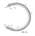
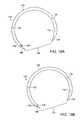
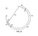
- FIG. 18is an expanded view of a curved suturing needle with notches on the surface of the needle.
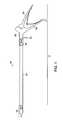
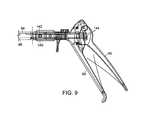
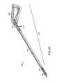
- the handle 60is a grip that is squeezed in order to actuate the suturing device 50 .
- the suturing device 50is actuated by the actuator mechanism 52 coupled to a drive mechanism 70 .
- the actuator mechanism 52 of the suturing device 50may comprise a triggering mechanism that is known in the art, such as for example, the triggering mechanisms disclosed in U.S. Pat. Nos. 6,053,908 and 5,344,061, both of which are hereby incorporated by reference.
- the actuator mechanismcan be either a manually operable button or switch, or a mechanically operable by an automated electrical or a fuel driven device, such as for example, an electrical, electromagnetic or pneumatic motor powered by electrical, electromagnetic, compressed air, compressed gas, hydraulic, vacuum or hydrocarbon fuels.
- any actuator mechanism of any type known in the artcan be within the spirit and scope of the presently disclosed embodiments.
- the improved visibility offered by the shape and configuration of the suture head assembly 56enables precise device placement over the incision, and uniform advancement of the suturing device 50 after every stitch to provide a uniform and symmetric suture, thereby minimizing the risk of tearing tissue and bleeding due to a stitch being positioned too close to the edge of the incised tissue.
- the entire device 50 or parts of the device 50such as the suture head assembly 56 , the elongated barrel 54 , the handle 60 , and the needle 120 and cartridge 88 , are composed of a sterilizable medical grade plastic material, in which case, the entire device 50 or parts of the device 50 may discarded and disposed after a single use.
- the opening 130is the form of an eye though which the leading end of the suturing material or thread 146 may be passed through for attachment to the needle 120 .
- the opening 130is located adjacent to the blunt end 126 .
- the opening 130can be positioned anywhere along the arc or the needle 120 between the apex 128 and the blunt end 126 .
- the needle 120comprises an opening 130 in the form of a cylindrical bore aligned axially with respect to the needle 120 , located at the blunt end 126 ( FIG. 19B ).
- the leading end of the suturing material or thread 146is inserted into the opening 130 and restrained by mechanically crimping.
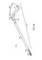
- the suture head assembly 156may be articulated, and the elongated barrel 154 may be any length appropriate for the intended clinical application of the device 150 .
- the diameter of the device 150can range from about 3 mm to about 20 mm. In an embodiment, the diameter of the device 150 is about 12 mm. In an embodiment, the diameter of the device 150 is about 3 mm.
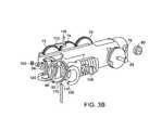
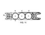
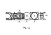
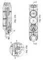
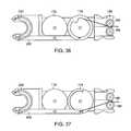
- FIGS. 27A and 27Bshow detailed views of the drive mechanism 170 located in the suture head assembly 156 with respect to driving the needle 220 during use of the device 150 (the needle holder assembly 188 and the holder assembly 190 have been removed to show the drive mechanism 170 in detail).
- the drive mechanism 170includes the actuator arm 202 that engages pulleys 172 , 174 , and 176 and the pawl 198 that drives the needle 220 through a curved path.
- the pawl 198is located in the distal end of the actuator arm 202 and is capable of engaging the notches 232 located along the face of the needle 220 .
- a flat spring 200keeps the pawl 198 engaged into the notches 232 of the needle 220 .
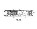
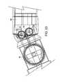
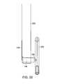
- FIG. 29shows a close-up view of the suture head assembly 156 with the needle holder assembly 188 , the holder assembly 190 , the latch 210 and the needle 220 in view as well as the relationship between the pawl 198 and the actuator arm 202 with respect to the needle 220 .
- the needle 220is enclosed within the needle holder assembly 188 , so the sharp pointed end 224 of the needle 220 is not exposed.
- This needle 220 position, as loaded,is referred to as the “home” position. In the home position, the needle 220 is fully contained within the needle holder assembly 188 to eliminate needle-pricks during handling of the suture head assembly 156 .
- the usermay continue to manipulate the suturing device 150 , alternately advancing and actuating rotation of the needle 220 about an axis that is generally parallel to the direction of advancement to create a continuous suture which may extend through the entire length of the incision or a series of interrupted stitches.
- the stitchis tightened by exerting a pull on the suturing material or thread 246 so that the resultant suture is tensioned uniformly along the length of the incised tissue segments. Therefore, a tight closure of the segments is accomplished and bleeding and tearing of tissue are minimized.
- the usercan use a needle grasper to tighten and knot the formed stitches.
Landscapes
- Health & Medical Sciences (AREA)
- Life Sciences & Earth Sciences (AREA)
- Surgery (AREA)
- Heart & Thoracic Surgery (AREA)
- Engineering & Computer Science (AREA)
- Biomedical Technology (AREA)
- Nuclear Medicine, Radiotherapy & Molecular Imaging (AREA)
- Medical Informatics (AREA)
- Molecular Biology (AREA)
- Animal Behavior & Ethology (AREA)
- General Health & Medical Sciences (AREA)
- Public Health (AREA)
- Veterinary Medicine (AREA)
- Surgical Instruments (AREA)
Abstract
Description
Claims (16)
Priority Applications (24)
| Application Number | Priority Date | Filing Date | Title |
|---|---|---|---|
| US11/231,135US7862572B2 (en) | 2004-09-20 | 2005-09-20 | Apparatus and method for minimally invasive suturing |
| US11/982,174US20080255590A1 (en) | 2002-04-22 | 2007-11-01 | Apparatus and method for minimally invasive suturing |
| US12/592,174US8123764B2 (en) | 2004-09-20 | 2009-11-20 | Apparatus and method for minimally invasive suturing |
| US13/361,444US8821519B2 (en) | 2004-09-20 | 2012-01-30 | Apparatus and method for minimally invasive suturing |
| US14/472,090US9451948B2 (en) | 2004-09-20 | 2014-08-28 | Apparatus and method for minimally invasive suturing |
| US14/796,642US9474523B2 (en) | 2004-09-20 | 2015-07-10 | Apparatus and method for minimally invasive suturing |
| US15/265,650US9597071B1 (en) | 2004-09-20 | 2016-09-14 | Apparatus and method for minimally invasive suturing |
| US15/357,375US9700301B2 (en) | 2004-09-20 | 2016-11-21 | Suturing needles |
| US15/357,533US9700302B2 (en) | 2004-09-20 | 2016-11-21 | Suturing needles |
| US15/358,210US9642613B1 (en) | 2004-09-20 | 2016-11-22 | Apparatus and method for minimally invasive suturing |
| US15/377,562US9675339B2 (en) | 2004-09-20 | 2016-12-13 | Devices and methods for minimally invasive suturing |
| US15/377,502US9642614B1 (en) | 2004-09-20 | 2016-12-13 | Apparatus and method for minimally invasive suturing |
| US15/480,915US9795377B2 (en) | 2004-09-20 | 2017-04-06 | Apparatus and method for minimally invasive suturing |
| US15/480,561US9795376B2 (en) | 2004-09-20 | 2017-04-06 | Apparatus and method for minimally invasive suturing |
| US15/480,933US9808238B2 (en) | 2004-09-20 | 2017-04-06 | Apparatus and method for minimally invasive suturing |
| US15/480,945US9936944B2 (en) | 2004-09-20 | 2017-04-06 | Apparatus and method for minimally invasive suturing |
| US15/640,452US9962153B2 (en) | 2004-09-20 | 2017-06-30 | Apparatus and method for minimally invasive suturing |
| US15/661,924US9962154B2 (en) | 2004-09-20 | 2017-07-27 | Apparatus and method for minimally invasive suturing |
| US15/671,450US9962155B2 (en) | 2004-09-20 | 2017-08-08 | Apparatus and method for minimally invasive suturing |
| US15/828,431US10098630B2 (en) | 2004-09-20 | 2017-11-30 | Apparatus and method for minimally invasive suturing |
| US15/885,509US10111654B2 (en) | 2004-09-20 | 2018-01-31 | Apparatus and method for minimally invasive suturing |
| US16/051,027US11253249B2 (en) | 2004-09-20 | 2018-07-31 | Apparatus and method for minimally invasive suturing |
| US16/905,758US11172922B2 (en) | 2004-09-20 | 2020-06-18 | Apparatus and method for minimally invasive suturing |
| US17/576,338US20220202413A1 (en) | 2004-09-20 | 2022-01-14 | Apparatus and method for minimally invasive suturing |
Applications Claiming Priority (2)
| Application Number | Priority Date | Filing Date | Title |
|---|---|---|---|
| US61136204P | 2004-09-20 | 2004-09-20 | |
| US11/231,135US7862572B2 (en) | 2004-09-20 | 2005-09-20 | Apparatus and method for minimally invasive suturing |
Related Parent Applications (2)
| Application Number | Title | Priority Date | Filing Date |
|---|---|---|---|
| US11/387,127Continuation-In-PartUS8066737B2 (en) | 2001-06-14 | 2006-03-22 | Needle for suturing instrument |
| PCT/US2008/006674Continuation-In-PartWO2008147555A2 (en) | 2004-09-20 | 2008-05-23 | Apparatus and method for minimally invasive suturing |
Related Child Applications (4)
| Application Number | Title | Priority Date | Filing Date |
|---|---|---|---|
| US11/982,174ContinuationUS20080255590A1 (en) | 2002-04-22 | 2007-11-01 | Apparatus and method for minimally invasive suturing |
| PCT/US2008/006674Continuation-In-PartWO2008147555A2 (en) | 2004-09-20 | 2008-05-23 | Apparatus and method for minimally invasive suturing |
| US12/175,442Continuation-In-PartUS7976555B2 (en) | 2004-09-20 | 2008-07-17 | Apparatus and method for minimally invasive suturing |
| US12/592,174Continuation-In-PartUS8123764B2 (en) | 2004-09-20 | 2009-11-20 | Apparatus and method for minimally invasive suturing |
Publications (2)
| Publication Number | Publication Date |
|---|---|
| US20060069396A1 US20060069396A1 (en) | 2006-03-30 |
| US7862572B2true US7862572B2 (en) | 2011-01-04 |
Family
ID=36090581
Family Applications (2)
| Application Number | Title | Priority Date | Filing Date |
|---|---|---|---|
| US11/231,135Active2029-07-28US7862572B2 (en) | 2002-04-22 | 2005-09-20 | Apparatus and method for minimally invasive suturing |
| US11/982,174AbandonedUS20080255590A1 (en) | 2002-04-22 | 2007-11-01 | Apparatus and method for minimally invasive suturing |
Family Applications After (1)
| Application Number | Title | Priority Date | Filing Date |
|---|---|---|---|
| US11/982,174AbandonedUS20080255590A1 (en) | 2002-04-22 | 2007-11-01 | Apparatus and method for minimally invasive suturing |
Country Status (4)
| Country | Link |
|---|---|
| US (2) | US7862572B2 (en) |
| EP (1) | EP1791476B1 (en) |
| JP (1) | JP4855405B2 (en) |
| WO (1) | WO2006034209A2 (en) |
Cited By (58)
| Publication number | Priority date | Publication date | Assignee | Title |
|---|---|---|---|---|
| US20090209980A1 (en)* | 2008-02-19 | 2009-08-20 | Harris Research, Llc. | Suturing and knot-tying device |
| US8419768B2 (en) | 2007-03-15 | 2013-04-16 | Covidien Lp | Surgical stapling apparatus with powered articulation |
| WO2013096855A1 (en)* | 2011-12-23 | 2013-06-27 | Arthrex, Inc. | Drive system for tissue repair |
| US20130165950A1 (en)* | 2011-12-27 | 2013-06-27 | Boston Scientific Scimed, Inc. | System and method to achieve reciprocating rotational motion of the distal member of a device by applying translational forces |
| US20140171975A1 (en)* | 2012-12-13 | 2014-06-19 | Ethicon Endo-Surgery, Inc. | Suturing Device with Reusable Shaft and Disposable Cartridge |
| US20140276988A1 (en)* | 2013-03-15 | 2014-09-18 | Invictus Medical Innovations, Llc | Suturer |
| US9125645B1 (en) | 2013-03-11 | 2015-09-08 | Ethicon Endo-Surgery, Inc. | Reciprocating needle drive without cables |
| USD745146S1 (en) | 2014-06-06 | 2015-12-08 | Ethicon Endo-Surgery, Inc. | Surgical suturing device |
| DE202015008237U1 (en) | 2015-11-25 | 2016-01-18 | Jörg Neymeyer | Surgical suturing instrument for minimally invasive transendoscopic suturing |
| KR20160038072A (en)* | 2011-08-08 | 2016-04-06 | 엔도에볼루션, 엘엘씨 | Devices and methods for minimally invasive suturing |
| US9370354B1 (en) | 2013-03-11 | 2016-06-21 | Ethicon Endo-Surgery, Llc | Automated needle loader |
| US9375212B2 (en) | 2014-06-06 | 2016-06-28 | Ethicon Endo-Surgery, Llc | Circular needle applier with cleats |
| US9474522B2 (en) | 2014-06-06 | 2016-10-25 | Ethicon Endo-Surgery, Llc | Jawed receiver for needle cartridge |
| USD771811S1 (en) | 2013-03-15 | 2016-11-15 | Ethicon Endo-Surgery, Llc | Suture tray |
| US20160367238A1 (en)* | 2015-06-16 | 2016-12-22 | Ethicon Endo-Surgery, Llc | Suturing instrument with jaw having integral cartridge component |
| US20160367239A1 (en)* | 2015-06-16 | 2016-12-22 | Ethicon Endo-Surgery, Llc | Suturing instrument with multi-mode cartridges |
| US20160367243A1 (en)* | 2015-06-16 | 2016-12-22 | Ethicon Endo-Surgery, Llc | Suturing instrument with motorized needle drive |
| US9597071B1 (en) | 2004-09-20 | 2017-03-21 | Endoevolution, Llc | Apparatus and method for minimally invasive suturing |
| US20170119376A1 (en) | 2001-06-14 | 2017-05-04 | Endoevolution, Llc | Devices and methods for surgical suturing |
| US9675339B2 (en) | 2004-09-20 | 2017-06-13 | Endoevolution, Llc | Devices and methods for minimally invasive suturing |
| US9782167B1 (en) | 2013-03-11 | 2017-10-10 | Ethicon Llc | Button actuated needle loader |
| US9788830B2 (en) | 2014-06-06 | 2017-10-17 | Ethicon Llc | Needle cartridge with cage |
| USD800306S1 (en) | 2015-12-10 | 2017-10-17 | Ethicon Llc | Surgical suturing device |
| US9820744B2 (en) | 2012-09-26 | 2017-11-21 | Children's National Medical Center | Anastomosis clipping tool with half-loop clip |
| US9867608B1 (en)* | 2015-06-16 | 2018-01-16 | Ethicon Endo-Surgery, Llc | Suturing instrument with circular needle motion |
| US9962156B2 (en) | 2006-01-27 | 2018-05-08 | Endoevolution, Llc | Suturing needle |
| US10004558B2 (en) | 2009-01-12 | 2018-06-26 | Ethicon Endo-Surgery, Inc. | Electrical ablation devices |
| US10022120B2 (en) | 2015-05-26 | 2018-07-17 | Ethicon Llc | Surgical needle with recessed features |
| WO2018156456A1 (en) | 2017-02-26 | 2018-08-30 | Endoevolution, Llc | Apparatus and method for minimally invasive suturing |
| US10098630B2 (en) | 2004-09-20 | 2018-10-16 | Endoevolution, Llc | Apparatus and method for minimally invasive suturing |
| US10105141B2 (en) | 2008-07-14 | 2018-10-23 | Ethicon Endo-Surgery, Inc. | Tissue apposition clip application methods |
| US10206709B2 (en) | 2012-05-14 | 2019-02-19 | Ethicon Llc | Apparatus for introducing an object into a patient |
| US10258406B2 (en) | 2011-02-28 | 2019-04-16 | Ethicon Llc | Electrical ablation devices and methods |
| US10278761B2 (en) | 2011-02-28 | 2019-05-07 | Ethicon Llc | Electrical ablation devices and methods |
| US10292698B2 (en) | 2017-07-27 | 2019-05-21 | Endoevolution, Llc | Apparatus and method for minimally invasive suturing |
| US10314603B2 (en) | 2008-11-25 | 2019-06-11 | Ethicon Llc | Rotational coupling device for surgical instrument with flexible actuators |
| US10342598B2 (en) | 2012-08-15 | 2019-07-09 | Ethicon Llc | Electrosurgical system for delivering a biphasic waveform |
| US10433831B2 (en) | 2015-06-01 | 2019-10-08 | Lsi Solutions, Inc. | Needle for a minimally invasive surgical suturing device |
| US10456128B2 (en) | 2005-06-13 | 2019-10-29 | Ethicon Llc | Method for suture lacing |
| USD865964S1 (en) | 2017-01-05 | 2019-11-05 | Ethicon Llc | Handle for electrosurgical instrument |
| US10478248B2 (en) | 2007-02-15 | 2019-11-19 | Ethicon Llc | Electroporation ablation apparatus, system, and method |
| US10492880B2 (en) | 2012-07-30 | 2019-12-03 | Ethicon Llc | Needle probe guide |
| US10542968B2 (en) | 2016-12-23 | 2020-01-28 | Brigham And Women's Hospital, Inc. | Systems and methods for suturing tissue |
| US10603031B2 (en) | 2017-02-03 | 2020-03-31 | Lsi Solutions, Inc. | Suturing device for minimally invasive surgery |
| US10709438B1 (en)* | 2015-06-15 | 2020-07-14 | Ethicon Llc | Suturing instrument with robotic drive interface |
| USD895112S1 (en) | 2018-11-15 | 2020-09-01 | Ethicon Llc | Laparoscopic bipolar electrosurgical device |
| US10779882B2 (en) | 2009-10-28 | 2020-09-22 | Ethicon Endo-Surgery, Inc. | Electrical ablation devices |
| US10799233B2 (en) | 2012-05-01 | 2020-10-13 | Brigham And Women's Hospital, Inc. | Suturing device for laparoscopic procedures |
| US11337688B2 (en) | 2015-06-01 | 2022-05-24 | Lsi Solutions, Inc. | Suturing device for minimally invasive surgery and needles and methods thereof |
| US11484191B2 (en) | 2013-02-27 | 2022-11-01 | Cilag Gmbh International | System for performing a minimally invasive surgical procedure |
| US11653912B2 (en) | 2019-12-12 | 2023-05-23 | Intuitive Surgical Operations, Inc. | Needle driver devices and related systems and methods |
| US11871969B2 (en) | 2021-03-03 | 2024-01-16 | Acustitch, Llc | System and method for osseous reconstruction and repair and implant device |
| US20240024047A1 (en)* | 2020-11-30 | 2024-01-25 | Intuitive Surgical Operations, Inc. | Systems for retracting and adjusting elongate flexible devices and associated methods |
| US11903865B2 (en) | 2015-09-15 | 2024-02-20 | Savage Medical, Inc. | Devices and methods for anchoring a sheath in a tissue cavity |
| US11918204B2 (en) | 2015-06-01 | 2024-03-05 | Lsi Solutions, Inc. | Suturing device for minimally invasive surgery and needles and methods thereof |
| US12201559B2 (en) | 2020-10-13 | 2025-01-21 | POSTECH Research and Business Development Foundation | Medical vacuum tweezer and tissue suturing device including the same |
| WO2025072601A1 (en)* | 2023-09-29 | 2025-04-03 | Regents Of The University Of Minnesota | Suturing device |
| US12402877B2 (en) | 2021-06-07 | 2025-09-02 | Intuitive Surgical Operations, Inc. | Needle loader devices and related systems and methods |
Families Citing this family (141)
| Publication number | Priority date | Publication date | Assignee | Title |
|---|---|---|---|---|
| US7862572B2 (en)* | 2004-09-20 | 2011-01-04 | Endoevolution, Llc | Apparatus and method for minimally invasive suturing |
| WO2004021873A2 (en)* | 2002-09-06 | 2004-03-18 | C.R. Bard, Inc. | Integrated endoscope and accessory treatment device |
| US20050267520A1 (en)* | 2004-05-12 | 2005-12-01 | Modesitt D B | Access and closure device and method |
| US7678133B2 (en)* | 2004-07-10 | 2010-03-16 | Arstasis, Inc. | Biological tissue closure device and method |
| US7993354B1 (en)* | 2010-10-01 | 2011-08-09 | Endoevolution, Llc | Devices and methods for minimally invasive suturing |
| CN103190942A (en)* | 2005-05-12 | 2013-07-10 | 阿尔斯塔西斯公司 | Access and closure device and method |
| US7628796B2 (en)* | 2005-06-13 | 2009-12-08 | Ethicon Endo-Surgery, Inc. | Surgical suturing apparatus with anti-backup system |
| US20060282097A1 (en)* | 2005-06-13 | 2006-12-14 | Ortiz Mark S | Surgical suturing apparatus with a non-visible spectrum sensing member |
| US8641728B2 (en) | 2005-06-13 | 2014-02-04 | Ethicon Endo-Surgery, Inc. | Attachment apparatus for coupling with an endoscope |
| US7615060B2 (en)* | 2005-06-13 | 2009-11-10 | Ethicon-Endo Surgery, Inc. | Endoscopic suturing device |
| US9545191B2 (en)* | 2005-06-13 | 2017-01-17 | Ethicon Endo-Surgery, Inc. | Method for suture lacing |
| US7846169B2 (en)* | 2005-06-13 | 2010-12-07 | Ethicon Endo-Surgery, Inc. | Adjustable vacuum chamber for a surgical suturing apparatus |
| US7766925B2 (en)* | 2005-06-13 | 2010-08-03 | Ethicon Endo-Surgery, Inc. | Surgical suturing apparatus |
| US8906040B2 (en)* | 2005-07-13 | 2014-12-09 | Creighton University | Systems and techniques for minimally invasive gastrointestinal procedures |
| US7686831B2 (en)* | 2006-03-31 | 2010-03-30 | Ethicon Endo-Surgery, Inc. | Method for securing a suture |
| US8118820B2 (en)* | 2006-03-31 | 2012-02-21 | Ethicon Endo-Surgery, Inc. | Method for instrument insertion through a body orifice |
| US20090281376A1 (en)* | 2006-04-19 | 2009-11-12 | Acosta Pablo G | Devices, system and methods for minimally invasive abdominal surgical procedures |
| US20110172767A1 (en)* | 2006-04-19 | 2011-07-14 | Pankaj Rathi | Minimally invasive, direct delivery methods for implanting obesity treatment devices |
| US7976554B2 (en)* | 2006-04-19 | 2011-07-12 | Vibrynt, Inc. | Devices, tools and methods for performing minimally invasive abdominal surgical procedures |
| US20090281386A1 (en)* | 2006-04-19 | 2009-11-12 | Acosta Pablo G | Devices, system and methods for minimally invasive abdominal surgical procedures |
| US20090272388A1 (en)* | 2006-04-19 | 2009-11-05 | Shuji Uemura | Minimally-invasive methods for implanting obesity treatment devices |
| US20090281563A1 (en)* | 2006-04-19 | 2009-11-12 | Newell Matthew B | Devices, tools and methods for performing minimally invasive abdominal surgical procedures |
| US20090275972A1 (en)* | 2006-04-19 | 2009-11-05 | Shuji Uemura | Minimally-invasive methods for implanting obesity treatment devices |
| US8585733B2 (en)* | 2006-04-19 | 2013-11-19 | Vibrynt, Inc | Devices, tools and methods for performing minimally invasive abdominal surgical procedures |
| US20090281500A1 (en)* | 2006-04-19 | 2009-11-12 | Acosta Pablo G | Devices, system and methods for minimally invasive abdominal surgical procedures |
| US8105355B2 (en) | 2006-05-18 | 2012-01-31 | C.R. Bard, Inc. | Suture lock fastening device |
| WO2008045374A2 (en)* | 2006-10-05 | 2008-04-17 | Tyco Healthcare Group Lp | Handle assembly for articulated endoscopic instruments |
| US8226667B2 (en) | 2006-10-05 | 2012-07-24 | Tyco Healthcare Group Lp | Axial stitching device |
| JP5481194B2 (en)* | 2006-10-05 | 2014-04-23 | コヴィディエン リミテッド パートナーシップ | Flexible endoscopic suturing device |
| US7481348B2 (en) | 2006-10-06 | 2009-01-27 | Tyco Healthcare Group Lp | Surgical instrument with articulating tool assembly |
| US20080200762A1 (en)* | 2007-02-16 | 2008-08-21 | Stokes Michael J | Flexible endoscope shapelock |
| US20080228185A1 (en)* | 2007-03-15 | 2008-09-18 | Amei Technologies, Inc. | Encompassing external fixation device with incorporated pemf coil |
| US8075572B2 (en) | 2007-04-26 | 2011-12-13 | Ethicon Endo-Surgery, Inc. | Surgical suturing apparatus |
| US8100922B2 (en)* | 2007-04-27 | 2012-01-24 | Ethicon Endo-Surgery, Inc. | Curved needle suturing tool |
| US20230248355A1 (en)* | 2007-05-24 | 2023-08-10 | Intuitive Surgical Operations, Inc. | Apparatus and method for minimally invasive suturing |
| US8262655B2 (en) | 2007-11-21 | 2012-09-11 | Ethicon Endo-Surgery, Inc. | Bipolar forceps |
| US8579897B2 (en) | 2007-11-21 | 2013-11-12 | Ethicon Endo-Surgery, Inc. | Bipolar forceps |
| US8568410B2 (en) | 2007-08-31 | 2013-10-29 | Ethicon Endo-Surgery, Inc. | Electrical ablation surgical instruments |
| AU2008302043B2 (en)* | 2007-09-21 | 2013-06-27 | Covidien Lp | Surgical device |
| US7703653B2 (en) | 2007-09-28 | 2010-04-27 | Tyco Healthcare Group Lp | Articulation mechanism for surgical instrument |
| US20090112059A1 (en) | 2007-10-31 | 2009-04-30 | Nobis Rudolph H | Apparatus and methods for closing a gastrotomy |
| US8480657B2 (en) | 2007-10-31 | 2013-07-09 | Ethicon Endo-Surgery, Inc. | Detachable distal overtube section and methods for forming a sealable opening in the wall of an organ |
| US7954685B2 (en)* | 2007-11-06 | 2011-06-07 | Tyco Healthcare Group Lp | Articulation and firing force mechanisms |
| US8262680B2 (en) | 2008-03-10 | 2012-09-11 | Ethicon Endo-Surgery, Inc. | Anastomotic device |
| US8864776B2 (en)* | 2008-04-11 | 2014-10-21 | Covidien Lp | Deployment system for surgical suture |
| US8652150B2 (en) | 2008-05-30 | 2014-02-18 | Ethicon Endo-Surgery, Inc. | Multifunction surgical device |
| US8679003B2 (en) | 2008-05-30 | 2014-03-25 | Ethicon Endo-Surgery, Inc. | Surgical device and endoscope including same |
| US8317806B2 (en) | 2008-05-30 | 2012-11-27 | Ethicon Endo-Surgery, Inc. | Endoscopic suturing tension controlling and indication devices |
| US8771260B2 (en) | 2008-05-30 | 2014-07-08 | Ethicon Endo-Surgery, Inc. | Actuating and articulating surgical device |
| US8070759B2 (en) | 2008-05-30 | 2011-12-06 | Ethicon Endo-Surgery, Inc. | Surgical fastening device |
| US8114072B2 (en) | 2008-05-30 | 2012-02-14 | Ethicon Endo-Surgery, Inc. | Electrical ablation device |
| US8906035B2 (en) | 2008-06-04 | 2014-12-09 | Ethicon Endo-Surgery, Inc. | Endoscopic drop off bag |
| US8403926B2 (en) | 2008-06-05 | 2013-03-26 | Ethicon Endo-Surgery, Inc. | Manually articulating devices |
| US8628545B2 (en)* | 2008-06-13 | 2014-01-14 | Covidien Lp | Endoscopic stitching devices |
| US20110040308A1 (en) | 2008-06-13 | 2011-02-17 | Ramiro Cabrera | Endoscopic Stitching Devices |
| US8361112B2 (en) | 2008-06-27 | 2013-01-29 | Ethicon Endo-Surgery, Inc. | Surgical suture arrangement |
| US20100010294A1 (en)* | 2008-07-10 | 2010-01-14 | Ethicon Endo-Surgery, Inc. | Temporarily positionable medical devices |
| US8262563B2 (en) | 2008-07-14 | 2012-09-11 | Ethicon Endo-Surgery, Inc. | Endoscopic translumenal articulatable steerable overtube |
| JP2011528605A (en)* | 2008-07-21 | 2011-11-24 | アルスタシス,インコーポレイテッド | Device, method, and kit for forming a tube in tissue |
| JP2011528606A (en)* | 2008-07-21 | 2011-11-24 | アルスタシス,インコーポレイテッド | Apparatus and method for forming a tract in tissue |
| US8801752B2 (en)* | 2008-08-04 | 2014-08-12 | Covidien Lp | Articulating surgical device |
| US8968355B2 (en) | 2008-08-04 | 2015-03-03 | Covidien Lp | Articulating surgical device |
| US8211125B2 (en) | 2008-08-15 | 2012-07-03 | Ethicon Endo-Surgery, Inc. | Sterile appliance delivery device for endoscopic procedures |
| US8529563B2 (en) | 2008-08-25 | 2013-09-10 | Ethicon Endo-Surgery, Inc. | Electrical ablation devices |
| US8241204B2 (en) | 2008-08-29 | 2012-08-14 | Ethicon Endo-Surgery, Inc. | Articulating end cap |
| US8480689B2 (en) | 2008-09-02 | 2013-07-09 | Ethicon Endo-Surgery, Inc. | Suturing device |
| US8409200B2 (en) | 2008-09-03 | 2013-04-02 | Ethicon Endo-Surgery, Inc. | Surgical grasping device |
| US8114119B2 (en) | 2008-09-09 | 2012-02-14 | Ethicon Endo-Surgery, Inc. | Surgical grasping device |
| US8337394B2 (en) | 2008-10-01 | 2012-12-25 | Ethicon Endo-Surgery, Inc. | Overtube with expandable tip |
| US8172772B2 (en)* | 2008-12-11 | 2012-05-08 | Ethicon Endo-Surgery, Inc. | Specimen retrieval device |
| US8828031B2 (en) | 2009-01-12 | 2014-09-09 | Ethicon Endo-Surgery, Inc. | Apparatus for forming an anastomosis |
| US8252057B2 (en) | 2009-01-30 | 2012-08-28 | Ethicon Endo-Surgery, Inc. | Surgical access device |
| US9226772B2 (en) | 2009-01-30 | 2016-01-05 | Ethicon Endo-Surgery, Inc. | Surgical device |
| US8037591B2 (en) | 2009-02-02 | 2011-10-18 | Ethicon Endo-Surgery, Inc. | Surgical scissors |
| US20100249700A1 (en)* | 2009-03-27 | 2010-09-30 | Ethicon Endo-Surgery, Inc. | Surgical instruments for in vivo assembly |
| US20110125178A1 (en)* | 2009-05-15 | 2011-05-26 | Michael Drews | Devices, methods and kits for forming tracts in tissue |
| US8132706B2 (en) | 2009-06-05 | 2012-03-13 | Tyco Healthcare Group Lp | Surgical stapling apparatus having articulation mechanism |
| USD708746S1 (en) | 2009-06-10 | 2014-07-08 | Covidien Lp | Handle for surgical device |
| US8490713B2 (en) | 2009-10-06 | 2013-07-23 | Covidien Lp | Handle assembly for endoscopic suturing device |
| US20110093009A1 (en)* | 2009-10-16 | 2011-04-21 | Ethicon Endo-Surgery, Inc. | Otomy closure device |
| US8608652B2 (en) | 2009-11-05 | 2013-12-17 | Ethicon Endo-Surgery, Inc. | Vaginal entry surgical devices, kit, system, and method |
| US8353487B2 (en) | 2009-12-17 | 2013-01-15 | Ethicon Endo-Surgery, Inc. | User interface support devices for endoscopic surgical instruments |
| US8496574B2 (en) | 2009-12-17 | 2013-07-30 | Ethicon Endo-Surgery, Inc. | Selectively positionable camera for surgical guide tube assembly |
| US8506564B2 (en) | 2009-12-18 | 2013-08-13 | Ethicon Endo-Surgery, Inc. | Surgical instrument comprising an electrode |
| US9028483B2 (en) | 2009-12-18 | 2015-05-12 | Ethicon Endo-Surgery, Inc. | Surgical instrument comprising an electrode |
| AU2011203850A1 (en)* | 2010-01-11 | 2012-08-02 | Arstasis, Inc. | Device for forming tracts in tissue |
| ES2662543T3 (en)* | 2010-01-26 | 2018-04-06 | Artack Medical (2013) Ltd. | Articulated medical instrument |
| US9005198B2 (en) | 2010-01-29 | 2015-04-14 | Ethicon Endo-Surgery, Inc. | Surgical instrument comprising an electrode |
| US10092291B2 (en) | 2011-01-25 | 2018-10-09 | Ethicon Endo-Surgery, Inc. | Surgical instrument with selectively rigidizable features |
| US8968340B2 (en) | 2011-02-23 | 2015-03-03 | Covidien Lp | Single actuating jaw flexible endolumenal stitching device |
| US9314620B2 (en) | 2011-02-28 | 2016-04-19 | Ethicon Endo-Surgery, Inc. | Electrical ablation devices and methods |
| US9049987B2 (en) | 2011-03-17 | 2015-06-09 | Ethicon Endo-Surgery, Inc. | Hand held surgical device for manipulating an internal magnet assembly within a patient |
| US9125644B2 (en)* | 2011-08-14 | 2015-09-08 | SafePath Medical, Inc. | Apparatus and method for suturing tissue |
| DK201170532A (en) | 2011-09-26 | 2013-03-27 | Coloplast As | Suturing device with suturing capsule removal mechanism |
| WO2013087095A1 (en)* | 2011-12-13 | 2013-06-20 | Ethicon Endo-Surgery, Inc. | An applier for anchoring a lining to a hollow organ |
| US9314362B2 (en) | 2012-01-08 | 2016-04-19 | Vibrynt, Inc. | Methods, instruments and devices for extragastric reduction of stomach volume |
| US8382775B1 (en) | 2012-01-08 | 2013-02-26 | Vibrynt, Inc. | Methods, instruments and devices for extragastric reduction of stomach volume |
| US8986199B2 (en) | 2012-02-17 | 2015-03-24 | Ethicon Endo-Surgery, Inc. | Apparatus and methods for cleaning the lens of an endoscope |
| US9326765B2 (en) | 2012-02-22 | 2016-05-03 | SafePath Medical, Inc. | Suturing device having an internal suture dispensing mechanism |
| US20130317438A1 (en) | 2012-05-25 | 2013-11-28 | Arstasis, Inc. | Vascular access configuration |
| US20130317481A1 (en) | 2012-05-25 | 2013-11-28 | Arstasis, Inc. | Vascular access configuration |
| US9078662B2 (en) | 2012-07-03 | 2015-07-14 | Ethicon Endo-Surgery, Inc. | Endoscopic cap electrode and method for using the same |
| US10314649B2 (en) | 2012-08-02 | 2019-06-11 | Ethicon Endo-Surgery, Inc. | Flexible expandable electrode and method of intraluminal delivery of pulsed power |
| US9572623B2 (en) | 2012-08-02 | 2017-02-21 | Ethicon Endo-Surgery, Inc. | Reusable electrode and disposable sheath |
| AU2015203325B2 (en)* | 2012-12-13 | 2016-11-03 | Ethicon Endo-Surgery, Inc. | Circular needle applier |
| US10231728B2 (en) | 2013-02-15 | 2019-03-19 | Surgimatix, Inc. | Medical fastening device |
| US9554793B2 (en) | 2013-03-16 | 2017-01-31 | SafePath Medical, Inc. | Means and methods for suturing tissue |
| CN104939881B (en)* | 2014-03-26 | 2017-03-22 | 瑞奇外科器械(中国)有限公司 | Driving device for surgical operating instrument and surgical operating instrument |
| EP3145421B1 (en) | 2014-05-17 | 2019-05-08 | Safepath Medical, Inc. | Systems for suturing tissue |
| US9877817B2 (en)* | 2014-05-22 | 2018-01-30 | Coloplast A/S | Surgical tool and system adapted to place a cuff of an artificial urinary sphincter around a portion of a urethra |
| US9468434B2 (en) | 2014-06-03 | 2016-10-18 | Covidien Lp | Stitching end effector |
| EP3294186B1 (en)* | 2015-05-15 | 2023-07-26 | Intuitive Surgical Operations, Inc. | System for minimally invasive cutting instrument operation |
| EP3302299A1 (en)* | 2015-05-26 | 2018-04-11 | Ethicon LLC | Surgical needle with recessed features |
| US10092286B2 (en) | 2015-05-27 | 2018-10-09 | Covidien Lp | Suturing loading unit |
| US10542970B2 (en) | 2016-05-31 | 2020-01-28 | Covidien Lp | Endoscopic stitching device |
| US10945723B2 (en) | 2016-11-17 | 2021-03-16 | SafePath Medical, Inc. | Systems and methods for suturing tissue |
| TR201700324A2 (en)* | 2017-01-10 | 2017-07-21 | Alper Celik | ENDOSCOPIC SEWING THREAD |
| US10751044B2 (en) | 2017-02-02 | 2020-08-25 | Covidien Lp | Vaginal tissue closure |
| US10709439B2 (en) | 2017-02-06 | 2020-07-14 | Covidien Lp | Endoscopic stitching device |
| CN107397565B (en)* | 2017-09-05 | 2023-09-01 | 山东省肿瘤防治研究院 | Mammary gland minimally invasive surgery stitching equipment and working method and application thereof |
| CN107981899B (en)* | 2017-12-22 | 2024-03-15 | 宁波胜杰康生物科技有限公司 | Minimally invasive suturing device |
| US12089835B2 (en)* | 2018-07-18 | 2024-09-17 | Atropos Limited | Device and system for hernia repair |
| CN109157251A (en)* | 2018-07-26 | 2019-01-08 | 刘立业 | The continuous stitching unstrument of hysteroscope |
| US11197665B2 (en) | 2018-08-06 | 2021-12-14 | Covidien Lp | Needle reload device for use with endostitch device |
| US20200323529A1 (en)* | 2019-04-11 | 2020-10-15 | Covidien Lp | Purse string suture device |
| US10736625B1 (en)* | 2019-10-24 | 2020-08-11 | Acustitch, Llc | System and method for suturing biological material |
| CN114828758A (en)* | 2020-01-13 | 2022-07-29 | 史密夫和内修有限公司 | Surgical instrument for manipulating and threading sutures |
| US11583270B2 (en)* | 2020-10-14 | 2023-02-21 | Matrixlabs Medical Co., Ltd | Needle set of laparoscopic surgery and knotting device thereof |
| CN112274201B (en)* | 2020-10-15 | 2021-07-23 | 苏州贝诺医疗器械有限公司 | Suture auxiliary instrument for laparoscopic surgery |
| KR102589511B1 (en)* | 2021-02-19 | 2023-10-16 | 고려대학교 산학협력단 | Endoscopic suturing apparatus |
| US20240225634A9 (en)* | 2021-03-01 | 2024-07-11 | Gyrus Acmi, Inc. D/B/A Olympus Surgical Technologies America | Electric suturing devices for endoscopy and laparoscopy |
| JP7708870B2 (en)* | 2021-03-01 | 2025-07-15 | ジャイラス エーシーエムアイ インク ディー/ビー/エー オリンパス サージカル テクノロジーズ アメリカ | Endoscope Including a Reinsertion Sheath and a Suturing Device - Patent application |
| CN112932575A (en)* | 2021-04-08 | 2021-06-11 | 深圳市玮琦实业有限公司 | Continuous stitching instrument |
| CN113827291A (en)* | 2021-10-09 | 2021-12-24 | 上海理工大学 | An in vivo rapid suturing device for minimally invasive surgery |
| CN118922145A (en)* | 2022-02-28 | 2024-11-08 | 利思梅德株式会社 | Surgical instrument and surgical robot including the same |
| CN115624359A (en)* | 2022-12-22 | 2023-01-20 | 北京派尔特医疗科技股份有限公司 | Electric suturing device |
| CN115944333B (en)* | 2022-12-22 | 2024-11-19 | 北京派尔特医疗科技股份有限公司 | Stitching device |
| CN119074210B (en)* | 2023-06-01 | 2025-10-03 | 深圳市精锋医疗科技股份有限公司 | Soft tissue suturing simulation method, device and medium |
| CN119055354A (en)* | 2023-06-01 | 2024-12-03 | 深圳市精锋医疗科技股份有限公司 | Soft tissue suturing simulation method, device and medium |
| CN119055356A (en)* | 2023-06-01 | 2024-12-03 | 深圳市精锋医疗科技股份有限公司 | Soft tissue suturing simulation method, device and medium |
| CN116983037B (en)* | 2023-09-25 | 2023-12-26 | 中南大学 | Bionic clamp type minimally invasive surgery stitching instrument |
Citations (84)
| Publication number | Priority date | Publication date | Assignee | Title |
|---|---|---|---|---|
| US1822330A (en) | 1930-01-13 | 1931-09-08 | Ainslie George | Suturing instrument |
| US3311110A (en) | 1964-07-15 | 1967-03-28 | American Cyanamid Co | Flexible composite suture having a tandem linkage |
| US3762418A (en) | 1972-05-17 | 1973-10-02 | W Wasson | Surgical suture |
| US3835912A (en) | 1973-06-25 | 1974-09-17 | S K S Ltd | Method of joining a filament to a metal rod |
| US4437465A (en) | 1979-05-17 | 1984-03-20 | Janome Sewing Machine Co., Ltd. | Medical treatment sewing machine |
| US4557265A (en) | 1983-02-08 | 1985-12-10 | Innova Ab | Suturing instrument |
| US4621640A (en) | 1984-01-09 | 1986-11-11 | Mulhollan James S | Mechanical needle carrier and method for its use |
| US5080663A (en) | 1990-09-26 | 1992-01-14 | Univerity College London | Sewing device |
| US5089012A (en) | 1989-02-20 | 1992-02-18 | Ethicon, Inc. | Surgical suture, in particular for sternotomy closure |
| US5306281A (en) | 1992-08-31 | 1994-04-26 | Merrimac Industries, Inc. | Suturing cassette device |
| US5308353A (en) | 1992-08-31 | 1994-05-03 | Merrimac Industries, Inc. | Surgical suturing device |
| US5364408A (en) | 1992-09-04 | 1994-11-15 | Laurus Medical Corporation | Endoscopic suture system |
| US5376101A (en) | 1992-10-09 | 1994-12-27 | The United States Surgical Corporation | Suture retaining clip |
| US5387221A (en) | 1991-01-17 | 1995-02-07 | Bisgaard; Therkel | Set of tools for suturing in deep surgical apertures or body cavities |
| US5437681A (en) | 1994-01-13 | 1995-08-01 | Suturtek Inc. | Suturing instrument with thread management |
| US5462558A (en) | 1994-08-29 | 1995-10-31 | United States Surgical Corporation | Suture clip applier |
| US5474568A (en) | 1993-10-08 | 1995-12-12 | United States Surgical Corporation | Instrument for closing trocar puncture wounds |
| US5514159A (en) | 1994-09-13 | 1996-05-07 | United States Surgical Corporation | Guillotine suture clip |
| US5540705A (en) | 1995-05-19 | 1996-07-30 | Suturtek, Inc. | Suturing instrument with thread management |
| US5571119A (en) | 1993-10-25 | 1996-11-05 | Children's Medical Center Corporation | Retractable suture needle with self-contained driver |
| US5643295A (en) | 1994-12-29 | 1997-07-01 | Yoon; Inbae | Methods and apparatus for suturing tissue |
| US5665096A (en) | 1995-03-07 | 1997-09-09 | Yoon; Inbae | Needle driving apparatus and methods of suturing tissue |
| US5665109A (en) | 1994-12-29 | 1997-09-09 | Yoon; Inbae | Methods and apparatus for suturing tissue |
| US5709693A (en) | 1996-02-20 | 1998-01-20 | Cardiothoracic System, Inc. | Stitcher |
| US5713910A (en) | 1992-09-04 | 1998-02-03 | Laurus Medical Corporation | Needle guidance system for endoscopic suture device |
| US5741277A (en) | 1992-09-04 | 1998-04-21 | Laurus Medical Corporation | Endoscopic suture system |
| US5759188A (en) | 1996-11-27 | 1998-06-02 | Yoon; Inbae | Suturing instrument with rotatably mounted needle driver and catcher |
| US5766186A (en) | 1996-12-03 | 1998-06-16 | Simon Fraser University | Suturing device |
| US5814071A (en) | 1994-11-10 | 1998-09-29 | Innovasive Devices, Inc. | Suture anchor assembly and methods |
| US5860992A (en) | 1996-01-31 | 1999-01-19 | Heartport, Inc. | Endoscopic suturing devices and methods |
| WO1999012482A1 (en) | 1997-09-11 | 1999-03-18 | Benny Gaber | Stitching tool |
| US5908428A (en) | 1997-05-27 | 1999-06-01 | United States Surgical Corporation | Stitching devices for heart valve replacement surgery |
| US5908426A (en) | 1997-04-24 | 1999-06-01 | Pierce; Javin | Suture needle manipulator |
| US5911727A (en)* | 1996-02-20 | 1999-06-15 | Cardiothoracic Systems, Inc. | Stitcher |
| US6036694A (en) | 1998-08-03 | 2000-03-14 | Innovasive Devices, Inc. | Self-tensioning soft tissue fixation device and method |
| US6048351A (en) | 1992-09-04 | 2000-04-11 | Scimed Life Systems, Inc. | Transvaginal suturing system |
| US6071289A (en) | 1999-03-15 | 2000-06-06 | Ethicon Endo-Surgery, Inc. | Surgical device for suturing tissue |
| US6136010A (en) | 1999-03-04 | 2000-10-24 | Perclose, Inc. | Articulating suturing device and method |
| US6159224A (en) | 1996-11-27 | 2000-12-12 | Yoon; Inbae | Multiple needle suturing instrument and method |
| US20020107530A1 (en) | 2001-02-02 | 2002-08-08 | Sauer Jude S. | System for endoscopic suturing |
| US6454778B2 (en) | 1998-03-20 | 2002-09-24 | Scimed Life Systems, Inc. | Endoscopic suture systems |
| US6494888B1 (en) | 1999-06-22 | 2002-12-17 | Ndo Surgical, Inc. | Tissue reconfiguration |
| US6506196B1 (en) | 1999-06-22 | 2003-01-14 | Ndo Surgical, Inc. | Device and method for correction of a painful body defect |
| US20030083674A1 (en) | 2001-10-04 | 2003-05-01 | Gibbens George H. | Cycling suturing and knot-tying device |
| US6558400B2 (en) | 2001-05-30 | 2003-05-06 | Satiety, Inc. | Obesity treatment tools and methods |
| US20030171760A1 (en) | 2000-05-19 | 2003-09-11 | Gambale Richard A | Tissue capturing and suturing device and method |
| US20030181924A1 (en) | 2002-01-30 | 2003-09-25 | Olympus Optical Co., Ltd. | Endoscopic suturing system |
| US6656194B1 (en) | 2002-11-05 | 2003-12-02 | Satiety, Inc. | Magnetic anchoring devices |
| US6663639B1 (en) | 1999-06-22 | 2003-12-16 | Ndo Surgical, Inc. | Methods and devices for tissue reconfiguration |
| US20030233108A1 (en) | 2002-06-12 | 2003-12-18 | Scimed Life Systems, Inc. | Endoscopic suture instrument |
| US20040034369A1 (en) | 2001-02-02 | 2004-02-19 | Sauer Jude S. | System for endoscopic suturing |
| US20040034372A1 (en) | 2002-08-02 | 2004-02-19 | Scimed Life Systems, Inc. | Placing sutures |
| US20040044354A1 (en) | 2002-08-30 | 2004-03-04 | Satiety, Inc. | Methods and devices for maintaining a space occupying device in a relatively fixed location within a stomach |
| US20040059350A1 (en) | 1992-09-04 | 2004-03-25 | Scimed Life Systems, Inc. | Suturing instruments and methods of use |
| US6719764B1 (en) | 2001-08-24 | 2004-04-13 | Scimed Life Systems, Inc. | Forward deploying suturing device and methods of use |
| US6719763B2 (en) | 2000-09-29 | 2004-04-13 | Olympus Optical Co., Ltd. | Endoscopic suturing device |
| US20040082963A1 (en) | 2002-10-23 | 2004-04-29 | Jamy Gannoe | Method and device for use in endoscopic organ procedures |
| US6746460B2 (en) | 2002-08-07 | 2004-06-08 | Satiety, Inc. | Intra-gastric fastening devices |
| US20040122473A1 (en) | 2002-12-11 | 2004-06-24 | Ewers Richard C. | Delivery systems and methods for gastric reduction |
| US6755843B2 (en) | 2000-09-29 | 2004-06-29 | Olympus Optical Co., Ltd. | Endoscopic suturing device |
| US20040138682A1 (en) | 2002-07-11 | 2004-07-15 | Olympus Optical Co., Ltd. | Endoscopic suture apparatus |
| US20040147958A1 (en) | 2002-12-11 | 2004-07-29 | Usgi Medical | Apparatus and methods for forming and securing gastrointestinal tissue folds |
| US20040147941A1 (en) | 2002-01-30 | 2004-07-29 | Olympus Corporation | Endoscopic suturing system |
| US20040162568A1 (en) | 1999-06-25 | 2004-08-19 | Usgi Medical | Apparatus and methods for forming and securing gastrointestinal tissue folds |
| US20040194790A1 (en) | 1999-06-22 | 2004-10-07 | Ndo Surgical, Inc. | Tissue reconfiguration |
| US20040210243A1 (en) | 2003-04-16 | 2004-10-21 | Jamy Gannoe | Method and devices for modifying the function of a body organ |
| US20040260344A1 (en) | 2003-05-07 | 2004-12-23 | Anpa Medical, Inc. | Suture lock |
| US6835200B2 (en) | 1999-06-22 | 2004-12-28 | Ndo Surgical. Inc. | Method and devices for tissue reconfiguration |
| US20050015101A1 (en) | 2001-10-04 | 2005-01-20 | Gibbens George H. | Leverage locking reversible cyclic suturing and knot-tying device |
| US20050055038A1 (en) | 2002-09-09 | 2005-03-10 | Brian Kelleher | Device and method for endoluminal therapy |
| US20050070931A1 (en) | 2003-08-06 | 2005-03-31 | Rhodemann Li | Method and apparatus for creating a restriction in the stomach or other anatomical structure |
| US6908427B2 (en) | 2002-12-30 | 2005-06-21 | PARÉ Surgical, Inc. | Flexible endoscope capsule |
| US6923819B2 (en) | 2001-06-14 | 2005-08-02 | Suturtek Incorporated | Apparatus and method for surgical suturing with thread management |
| US20060069396A1 (en) | 2004-09-20 | 2006-03-30 | Suturtek Incorporated | Apparatus and method for minimally invasive suturing |
| US7144401B2 (en) | 2001-06-07 | 2006-12-05 | Olympus Optical Co., Ltd. | Suturing device for endoscope |
| US20060282099A1 (en) | 2005-06-13 | 2006-12-14 | Stokes Michael J | Method for suture lacing |
| US20060282098A1 (en) | 2005-06-13 | 2006-12-14 | Shelton Frederick E Iv | Surgical suturing apparatus with detachable handle |
| US20060282089A1 (en) | 2005-06-13 | 2006-12-14 | Ethicon Endo-Surgery, Inc. | Endoscopic suturing device |
| US20060282093A1 (en) | 2005-06-13 | 2006-12-14 | Shelton Frederick E Iv | Surgical suturing apparatus with anti-backup system |
| US20060282091A1 (en) | 2005-06-13 | 2006-12-14 | Shelton Frederick E Iv | Adjustable vacuum chamber for a surgical suturing apparatus |
| US20060282094A1 (en) | 2005-06-13 | 2006-12-14 | Stokes Michael J | Surgical suturing apparatus |
| WO2007089603A2 (en) | 2006-01-27 | 2007-08-09 | Suturtek Incorporated | Apparatus and method for tissue closure |
| WO2008147555A2 (en) | 2007-05-24 | 2008-12-04 | Suturtek Incorporated | Apparatus and method for minimally invasive suturing |
| WO2010062380A2 (en) | 2008-11-25 | 2010-06-03 | Endoevolution, Llc | Apparatus and method for minimally invasive suturing |
Family Cites Families (6)
| Publication number | Priority date | Publication date | Assignee | Title |
|---|---|---|---|---|
| US5373101A (en)* | 1991-05-03 | 1994-12-13 | Motorola, Inc. | Electrical interconnect apparatus |
| US5303281A (en)* | 1992-07-09 | 1994-04-12 | Varian Associates, Inc. | Mammography method and improved mammography X-ray tube |
| US5305281A (en)* | 1992-08-06 | 1994-04-19 | National Semiconductor Corporation | Multiple array memory device with staggered read/write for high speed data access |
| US5993466A (en)* | 1997-06-17 | 1999-11-30 | Yoon; Inbae | Suturing instrument with multiple rotatably mounted spreadable needle holders |
| IL123275A0 (en)* | 1998-02-12 | 1998-09-24 | Urogyn Ltd | Surgical suture instrument |
| JP4127021B2 (en)* | 2002-11-06 | 2008-07-30 | トヨタ自動車株式会社 | Hard particles, wear-resistant iron-based sintered alloy, method for producing wear-resistant iron-based sintered alloy, and valve seat |
- 2005
- 2005-09-20USUS11/231,135patent/US7862572B2/enactiveActive
- 2005-09-20JPJP2007532595Apatent/JP4855405B2/ennot_activeExpired - Lifetime
- 2005-09-20WOPCT/US2005/033507patent/WO2006034209A2/enactiveApplication Filing
- 2005-09-20EPEP05797831.4Apatent/EP1791476B1/ennot_activeExpired - Lifetime
- 2007
- 2007-11-01USUS11/982,174patent/US20080255590A1/ennot_activeAbandoned
Patent Citations (98)
| Publication number | Priority date | Publication date | Assignee | Title |
|---|---|---|---|---|
| US1822330A (en) | 1930-01-13 | 1931-09-08 | Ainslie George | Suturing instrument |
| US3311110A (en) | 1964-07-15 | 1967-03-28 | American Cyanamid Co | Flexible composite suture having a tandem linkage |
| US3762418A (en) | 1972-05-17 | 1973-10-02 | W Wasson | Surgical suture |
| US3835912A (en) | 1973-06-25 | 1974-09-17 | S K S Ltd | Method of joining a filament to a metal rod |
| US4437465A (en) | 1979-05-17 | 1984-03-20 | Janome Sewing Machine Co., Ltd. | Medical treatment sewing machine |
| US4557265A (en) | 1983-02-08 | 1985-12-10 | Innova Ab | Suturing instrument |
| US4621640A (en) | 1984-01-09 | 1986-11-11 | Mulhollan James S | Mechanical needle carrier and method for its use |
| US5089012A (en) | 1989-02-20 | 1992-02-18 | Ethicon, Inc. | Surgical suture, in particular for sternotomy closure |
| US5080663A (en) | 1990-09-26 | 1992-01-14 | Univerity College London | Sewing device |
| US5387221A (en) | 1991-01-17 | 1995-02-07 | Bisgaard; Therkel | Set of tools for suturing in deep surgical apertures or body cavities |
| US5306281A (en) | 1992-08-31 | 1994-04-26 | Merrimac Industries, Inc. | Suturing cassette device |
| US5308353A (en) | 1992-08-31 | 1994-05-03 | Merrimac Industries, Inc. | Surgical suturing device |
| US20040059350A1 (en) | 1992-09-04 | 2004-03-25 | Scimed Life Systems, Inc. | Suturing instruments and methods of use |
| US5364408A (en) | 1992-09-04 | 1994-11-15 | Laurus Medical Corporation | Endoscopic suture system |
| US6048351A (en) | 1992-09-04 | 2000-04-11 | Scimed Life Systems, Inc. | Transvaginal suturing system |
| US7033370B2 (en) | 1992-09-04 | 2006-04-25 | Boston Scientific Scimed, Inc. | Suturing instruments and methods of use |
| US6346111B1 (en) | 1992-09-04 | 2002-02-12 | Scimed Life Systems, Inc. | Suturing instruments and methods of use |
| US5741277A (en) | 1992-09-04 | 1998-04-21 | Laurus Medical Corporation | Endoscopic suture system |
| US5713910A (en) | 1992-09-04 | 1998-02-03 | Laurus Medical Corporation | Needle guidance system for endoscopic suture device |
| US5376101A (en) | 1992-10-09 | 1994-12-27 | The United States Surgical Corporation | Suture retaining clip |
| US5474568A (en) | 1993-10-08 | 1995-12-12 | United States Surgical Corporation | Instrument for closing trocar puncture wounds |
| US5571119A (en) | 1993-10-25 | 1996-11-05 | Children's Medical Center Corporation | Retractable suture needle with self-contained driver |
| US5437681A (en) | 1994-01-13 | 1995-08-01 | Suturtek Inc. | Suturing instrument with thread management |
| US5462558A (en) | 1994-08-29 | 1995-10-31 | United States Surgical Corporation | Suture clip applier |
| US5514159A (en) | 1994-09-13 | 1996-05-07 | United States Surgical Corporation | Guillotine suture clip |
| US5814071A (en) | 1994-11-10 | 1998-09-29 | Innovasive Devices, Inc. | Suture anchor assembly and methods |
| US5665109A (en) | 1994-12-29 | 1997-09-09 | Yoon; Inbae | Methods and apparatus for suturing tissue |
| US5643295A (en) | 1994-12-29 | 1997-07-01 | Yoon; Inbae | Methods and apparatus for suturing tissue |
| US5665096A (en) | 1995-03-07 | 1997-09-09 | Yoon; Inbae | Needle driving apparatus and methods of suturing tissue |
| US5540705A (en) | 1995-05-19 | 1996-07-30 | Suturtek, Inc. | Suturing instrument with thread management |
| US5860992A (en) | 1996-01-31 | 1999-01-19 | Heartport, Inc. | Endoscopic suturing devices and methods |
| US5911727A (en)* | 1996-02-20 | 1999-06-15 | Cardiothoracic Systems, Inc. | Stitcher |
| US5709693A (en) | 1996-02-20 | 1998-01-20 | Cardiothoracic System, Inc. | Stitcher |
| US5759188A (en) | 1996-11-27 | 1998-06-02 | Yoon; Inbae | Suturing instrument with rotatably mounted needle driver and catcher |
| US6159224A (en) | 1996-11-27 | 2000-12-12 | Yoon; Inbae | Multiple needle suturing instrument and method |
| US5766186A (en) | 1996-12-03 | 1998-06-16 | Simon Fraser University | Suturing device |
| US5908426A (en) | 1997-04-24 | 1999-06-01 | Pierce; Javin | Suture needle manipulator |
| US5908428A (en) | 1997-05-27 | 1999-06-01 | United States Surgical Corporation | Stitching devices for heart valve replacement surgery |
| WO1999012482A1 (en) | 1997-09-11 | 1999-03-18 | Benny Gaber | Stitching tool |
| US6443962B1 (en) | 1997-09-11 | 2002-09-03 | Benny Gaber | Stitching tool |
| US6454778B2 (en) | 1998-03-20 | 2002-09-24 | Scimed Life Systems, Inc. | Endoscopic suture systems |
| US6036694A (en) | 1998-08-03 | 2000-03-14 | Innovasive Devices, Inc. | Self-tensioning soft tissue fixation device and method |
| US6136010A (en) | 1999-03-04 | 2000-10-24 | Perclose, Inc. | Articulating suturing device and method |
| US6071289A (en) | 1999-03-15 | 2000-06-06 | Ethicon Endo-Surgery, Inc. | Surgical device for suturing tissue |
| US6494888B1 (en) | 1999-06-22 | 2002-12-17 | Ndo Surgical, Inc. | Tissue reconfiguration |
| US6835200B2 (en) | 1999-06-22 | 2004-12-28 | Ndo Surgical. Inc. | Method and devices for tissue reconfiguration |
| US20040194790A1 (en) | 1999-06-22 | 2004-10-07 | Ndo Surgical, Inc. | Tissue reconfiguration |
| US6663639B1 (en) | 1999-06-22 | 2003-12-16 | Ndo Surgical, Inc. | Methods and devices for tissue reconfiguration |
| US6506196B1 (en) | 1999-06-22 | 2003-01-14 | Ndo Surgical, Inc. | Device and method for correction of a painful body defect |
| US20050075653A1 (en) | 1999-06-25 | 2005-04-07 | Usgi Medical Inc. | Apparatus and methods for forming and securing gastrointestinal tissue folds |
| US20040162568A1 (en) | 1999-06-25 | 2004-08-19 | Usgi Medical | Apparatus and methods for forming and securing gastrointestinal tissue folds |
| US20030171760A1 (en) | 2000-05-19 | 2003-09-11 | Gambale Richard A | Tissue capturing and suturing device and method |
| US6755843B2 (en) | 2000-09-29 | 2004-06-29 | Olympus Optical Co., Ltd. | Endoscopic suturing device |
| US6719763B2 (en) | 2000-09-29 | 2004-04-13 | Olympus Optical Co., Ltd. | Endoscopic suturing device |
| US20040034369A1 (en) | 2001-02-02 | 2004-02-19 | Sauer Jude S. | System for endoscopic suturing |
| US20020107530A1 (en) | 2001-02-02 | 2002-08-08 | Sauer Jude S. | System for endoscopic suturing |
| US6558400B2 (en) | 2001-05-30 | 2003-05-06 | Satiety, Inc. | Obesity treatment tools and methods |
| US7144401B2 (en) | 2001-06-07 | 2006-12-05 | Olympus Optical Co., Ltd. | Suturing device for endoscope |
| US6923819B2 (en) | 2001-06-14 | 2005-08-02 | Suturtek Incorporated | Apparatus and method for surgical suturing with thread management |
| US6719764B1 (en) | 2001-08-24 | 2004-04-13 | Scimed Life Systems, Inc. | Forward deploying suturing device and methods of use |
| US20050015101A1 (en) | 2001-10-04 | 2005-01-20 | Gibbens George H. | Leverage locking reversible cyclic suturing and knot-tying device |
| US7004951B2 (en) | 2001-10-04 | 2006-02-28 | Gibbens Group Llc | Cycling suturing and knot-tying device |
| US20030083674A1 (en) | 2001-10-04 | 2003-05-01 | Gibbens George H. | Cycling suturing and knot-tying device |
| US20030181924A1 (en) | 2002-01-30 | 2003-09-25 | Olympus Optical Co., Ltd. | Endoscopic suturing system |
| US20040147941A1 (en) | 2002-01-30 | 2004-07-29 | Olympus Corporation | Endoscopic suturing system |
| US6955643B2 (en) | 2002-06-12 | 2005-10-18 | Boston Scientific Scimed, Inc. | Endoscopic suture instrument |
| US20030233108A1 (en) | 2002-06-12 | 2003-12-18 | Scimed Life Systems, Inc. | Endoscopic suture instrument |
| US20030233104A1 (en) | 2002-06-12 | 2003-12-18 | Scimed Life Systems, Inc. | Suturing instrument with deflectable head |
| US20040138682A1 (en) | 2002-07-11 | 2004-07-15 | Olympus Optical Co., Ltd. | Endoscopic suture apparatus |
| US20040034372A1 (en) | 2002-08-02 | 2004-02-19 | Scimed Life Systems, Inc. | Placing sutures |
| US7041111B2 (en) | 2002-08-02 | 2006-05-09 | Boston Scientific Scimed, Inc. | Placing sutures |
| US6746460B2 (en) | 2002-08-07 | 2004-06-08 | Satiety, Inc. | Intra-gastric fastening devices |
| US20040044354A1 (en) | 2002-08-30 | 2004-03-04 | Satiety, Inc. | Methods and devices for maintaining a space occupying device in a relatively fixed location within a stomach |
| US20050055038A1 (en) | 2002-09-09 | 2005-03-10 | Brian Kelleher | Device and method for endoluminal therapy |
| US20040082963A1 (en) | 2002-10-23 | 2004-04-29 | Jamy Gannoe | Method and device for use in endoscopic organ procedures |
| US6656194B1 (en) | 2002-11-05 | 2003-12-02 | Satiety, Inc. | Magnetic anchoring devices |
| US20040088008A1 (en) | 2002-11-05 | 2004-05-06 | Satiety, Inc. | Magnetic anchoring devices |
| US20040147958A1 (en) | 2002-12-11 | 2004-07-29 | Usgi Medical | Apparatus and methods for forming and securing gastrointestinal tissue folds |
| US20040122473A1 (en) | 2002-12-11 | 2004-06-24 | Ewers Richard C. | Delivery systems and methods for gastric reduction |
| US6908427B2 (en) | 2002-12-30 | 2005-06-21 | PARÉ Surgical, Inc. | Flexible endoscope capsule |
| US20040210243A1 (en) | 2003-04-16 | 2004-10-21 | Jamy Gannoe | Method and devices for modifying the function of a body organ |
| US20040260344A1 (en) | 2003-05-07 | 2004-12-23 | Anpa Medical, Inc. | Suture lock |
| US20050070931A1 (en) | 2003-08-06 | 2005-03-31 | Rhodemann Li | Method and apparatus for creating a restriction in the stomach or other anatomical structure |
| US20060069396A1 (en) | 2004-09-20 | 2006-03-30 | Suturtek Incorporated | Apparatus and method for minimally invasive suturing |
| US20060282094A1 (en) | 2005-06-13 | 2006-12-14 | Stokes Michael J | Surgical suturing apparatus |
| US20060282097A1 (en) | 2005-06-13 | 2006-12-14 | Ortiz Mark S | Surgical suturing apparatus with a non-visible spectrum sensing member |
| US20060282089A1 (en) | 2005-06-13 | 2006-12-14 | Ethicon Endo-Surgery, Inc. | Endoscopic suturing device |
| US20060282090A1 (en) | 2005-06-13 | 2006-12-14 | Stokes Michael J | Surgical suturing apparatus with needle release system |
| US20060282093A1 (en) | 2005-06-13 | 2006-12-14 | Shelton Frederick E Iv | Surgical suturing apparatus with anti-backup system |
| US20060282091A1 (en) | 2005-06-13 | 2006-12-14 | Shelton Frederick E Iv | Adjustable vacuum chamber for a surgical suturing apparatus |
| US20060282099A1 (en) | 2005-06-13 | 2006-12-14 | Stokes Michael J | Method for suture lacing |
| US20060282098A1 (en) | 2005-06-13 | 2006-12-14 | Shelton Frederick E Iv | Surgical suturing apparatus with detachable handle |
| US20060282092A1 (en) | 2005-06-13 | 2006-12-14 | Stokes Michael J | Surgical suturing apparatus with needle position indicator |
| US20060282096A1 (en) | 2005-06-13 | 2006-12-14 | Papa Christopher A | Quick load mechanism for a surgical suturing apparatus |
| US20060282095A1 (en) | 2005-06-13 | 2006-12-14 | Stokes Michael J | Surgical suturing apparatus with collapsible vacuum chamber |
| WO2007089603A2 (en) | 2006-01-27 | 2007-08-09 | Suturtek Incorporated | Apparatus and method for tissue closure |
| WO2008147555A2 (en) | 2007-05-24 | 2008-12-04 | Suturtek Incorporated | Apparatus and method for minimally invasive suturing |
| WO2010062380A2 (en) | 2008-11-25 | 2010-06-03 | Endoevolution, Llc | Apparatus and method for minimally invasive suturing |
Non-Patent Citations (3)
| Title |
|---|
| International Search Report and The Written Opinion of the International Searching Authority (ISA) dated Jul. 5, 2010 relating to co-pending PCT/US2009/006212. |
| International Search Report and The Written Opinion of the International Searching Authority (ISA) dated Nov. 1, 2007. |
| International Search Report and The Written Opinion of the International Searching Authority dated Jun. 13, 2008. |
Cited By (132)
| Publication number | Priority date | Publication date | Assignee | Title |
|---|---|---|---|---|
| US9743923B2 (en) | 2001-06-14 | 2017-08-29 | Endoevolution, Llc | Devices and methods for surgical suturing |
| US9649107B2 (en) | 2001-06-14 | 2017-05-16 | Endoevolution, Llc | Needle for suturing instrument |
| US20170119376A1 (en) | 2001-06-14 | 2017-05-04 | Endoevolution, Llc | Devices and methods for surgical suturing |
| US10792032B2 (en) | 2001-06-14 | 2020-10-06 | Intuitive Surgical Operations, Inc. | Methods of surgical fastening |
| US9717495B1 (en) | 2001-06-14 | 2017-08-01 | Endoevolution, Llc | Devices and methods for surgical suturing |
| US9717493B1 (en) | 2001-06-14 | 2017-08-01 | Endoevolution, Llc | Devices and methods for surgical suturing |
| US9730688B1 (en) | 2001-06-14 | 2017-08-15 | Endoevolution, Llc | Devices and methods for surgical suturing |
| US10045774B2 (en) | 2001-06-14 | 2018-08-14 | Endoevolution, Llc | Devices and methods for surgical fastening |
| US9693770B2 (en) | 2001-06-14 | 2017-07-04 | Endoevolution, Llc | Devices and methods for surgical suturing |
| US9737296B1 (en) | 2001-06-14 | 2017-08-22 | Endoevolution, Llc | Devices and methods for surgical suturing |
| US9743925B2 (en) | 2001-06-14 | 2017-08-29 | Endoevolution, Llc | Devices and methods for surgical suturing |
| US9962152B2 (en) | 2001-06-14 | 2018-05-08 | Endoevolution, Llc | Devices and methods for surgical suturing |
| US9943308B2 (en) | 2001-06-14 | 2018-04-17 | Endoevolution, Llc | Devices and methods for surgical suturing |
| US9943307B2 (en) | 2001-06-14 | 2018-04-17 | Endoevolution, Llc | Devices and methods for surgical suturing |
| US9936945B2 (en) | 2001-06-14 | 2018-04-10 | Endoevolution, Llc | Devices and methods for surgical suturing |
| US9962155B2 (en) | 2004-09-20 | 2018-05-08 | Endoevolution, Llc | Apparatus and method for minimally invasive suturing |
| US11172922B2 (en)* | 2004-09-20 | 2021-11-16 | Intuitive Surgical Operations, Inc. | Apparatus and method for minimally invasive suturing |
| US9795377B2 (en) | 2004-09-20 | 2017-10-24 | Endoevolution, Llc | Apparatus and method for minimally invasive suturing |
| US9795376B2 (en) | 2004-09-20 | 2017-10-24 | Endoevolution, Llc | Apparatus and method for minimally invasive suturing |
| US9936944B2 (en) | 2004-09-20 | 2018-04-10 | Endoevolution, Llc | Apparatus and method for minimally invasive suturing |
| US9962153B2 (en) | 2004-09-20 | 2018-05-08 | Endoevolution, Llc | Apparatus and method for minimally invasive suturing |
| US9962154B2 (en) | 2004-09-20 | 2018-05-08 | Endoevolution, Llc | Apparatus and method for minimally invasive suturing |
| US10098630B2 (en) | 2004-09-20 | 2018-10-16 | Endoevolution, Llc | Apparatus and method for minimally invasive suturing |
| US10111654B2 (en) | 2004-09-20 | 2018-10-30 | Endoevolution, Llc | Apparatus and method for minimally invasive suturing |
| US9675339B2 (en) | 2004-09-20 | 2017-06-13 | Endoevolution, Llc | Devices and methods for minimally invasive suturing |
| US9700302B2 (en) | 2004-09-20 | 2017-07-11 | Endoevolution, Llc | Suturing needles |
| US9700301B2 (en) | 2004-09-20 | 2017-07-11 | Endoevolution, Llc | Suturing needles |
| US9597071B1 (en) | 2004-09-20 | 2017-03-21 | Endoevolution, Llc | Apparatus and method for minimally invasive suturing |
| US9808238B2 (en) | 2004-09-20 | 2017-11-07 | Endoevolution, Llc | Apparatus and method for minimally invasive suturing |
| US9642614B1 (en) | 2004-09-20 | 2017-05-09 | Endoevolution, Llc | Apparatus and method for minimally invasive suturing |
| US9642613B1 (en) | 2004-09-20 | 2017-05-09 | Endoevolution, Llc | Apparatus and method for minimally invasive suturing |
| US11253249B2 (en) | 2004-09-20 | 2022-02-22 | Intuitive Surgical Operations, Inc. | Apparatus and method for minimally invasive suturing |
| US10456128B2 (en) | 2005-06-13 | 2019-10-29 | Ethicon Llc | Method for suture lacing |
| US9986997B2 (en) | 2006-01-27 | 2018-06-05 | Endoevolution, Llc | Apparatus and method for tissue closure |
| US10383622B2 (en) | 2006-01-27 | 2019-08-20 | Endoevolution, Llc | Apparatus and method for tissue closure |
| US12150645B2 (en) | 2006-01-27 | 2024-11-26 | Intuitive Surgical Operations, Inc. | Systems and methods for tissue closure |
| US9962156B2 (en) | 2006-01-27 | 2018-05-08 | Endoevolution, Llc | Suturing needle |
| US10307155B2 (en) | 2006-01-27 | 2019-06-04 | Endoevolution, Llc | Apparatus and method for tissue closure |
| US11033262B2 (en) | 2006-01-27 | 2021-06-15 | Intuitive Surgical Operations, Inc. | Apparatus and method for tissue closure |
| US10478248B2 (en) | 2007-02-15 | 2019-11-19 | Ethicon Llc | Electroporation ablation apparatus, system, and method |
| US8419768B2 (en) | 2007-03-15 | 2013-04-16 | Covidien Lp | Surgical stapling apparatus with powered articulation |
| US9700314B2 (en) | 2007-03-15 | 2017-07-11 | Covidien Lp | Surgical stapling apparatus with powered articulation |
| US9192381B2 (en) | 2007-03-15 | 2015-11-24 | Covidien Lp | Surgical stapling apparatus with powered articulation |
| US20090209980A1 (en)* | 2008-02-19 | 2009-08-20 | Harris Research, Llc. | Suturing and knot-tying device |
| US11399834B2 (en) | 2008-07-14 | 2022-08-02 | Cilag Gmbh International | Tissue apposition clip application methods |
| US10105141B2 (en) | 2008-07-14 | 2018-10-23 | Ethicon Endo-Surgery, Inc. | Tissue apposition clip application methods |
| US10314603B2 (en) | 2008-11-25 | 2019-06-11 | Ethicon Llc | Rotational coupling device for surgical instrument with flexible actuators |
| US10004558B2 (en) | 2009-01-12 | 2018-06-26 | Ethicon Endo-Surgery, Inc. | Electrical ablation devices |
| US10779882B2 (en) | 2009-10-28 | 2020-09-22 | Ethicon Endo-Surgery, Inc. | Electrical ablation devices |
| US11986179B2 (en) | 2010-10-01 | 2024-05-21 | Intuitive Surgical Operations, Inc. | Devices and methods for minimally invasive suturing |
| US9775600B2 (en) | 2010-10-01 | 2017-10-03 | Endoevolution, Llc | Devices and methods for minimally invasive suturing |
| US10792031B2 (en) | 2010-10-01 | 2020-10-06 | Intuitive Surgical Operations, Inc. | Devices and methods for minimally invasive suturing |
| US9962151B2 (en) | 2010-10-01 | 2018-05-08 | Endoevolution, Llc | Devices and methods for minimally invasive suturing |
| US10881392B2 (en) | 2010-10-01 | 2021-01-05 | Intuitive Surgical Operations, Inc. | Devices and methods for minimally invasive suturing |
| US10278761B2 (en) | 2011-02-28 | 2019-05-07 | Ethicon Llc | Electrical ablation devices and methods |
| US10258406B2 (en) | 2011-02-28 | 2019-04-16 | Ethicon Llc | Electrical ablation devices and methods |
| KR20160038072A (en)* | 2011-08-08 | 2016-04-06 | 엔도에볼루션, 엘엘씨 | Devices and methods for minimally invasive suturing |
| KR101868007B1 (en)* | 2011-08-08 | 2018-06-15 | 엔도에볼루션, 엘엘씨 | Devices and methods for minimally invasive suturing |
| US9351722B2 (en) | 2011-12-23 | 2016-05-31 | Arthrex, Inc. | Drive system for tissue repair |
| WO2013096855A1 (en)* | 2011-12-23 | 2013-06-27 | Arthrex, Inc. | Drive system for tissue repair |
| US20130165950A1 (en)* | 2011-12-27 | 2013-06-27 | Boston Scientific Scimed, Inc. | System and method to achieve reciprocating rotational motion of the distal member of a device by applying translational forces |
| US12089834B2 (en) | 2012-05-01 | 2024-09-17 | The Brigham And Women's Hospital, Inc. | Suturing device for laparoscopic procedures |
| US10799233B2 (en) | 2012-05-01 | 2020-10-13 | Brigham And Women's Hospital, Inc. | Suturing device for laparoscopic procedures |
| US11717283B2 (en) | 2012-05-01 | 2023-08-08 | The Brigham And Women's Hospital, Inc. | Suturing device for laparoscopic procedures |
| US10206709B2 (en) | 2012-05-14 | 2019-02-19 | Ethicon Llc | Apparatus for introducing an object into a patient |
| US11284918B2 (en) | 2012-05-14 | 2022-03-29 | Cilag GmbH Inlernational | Apparatus for introducing a steerable camera assembly into a patient |
| US10492880B2 (en) | 2012-07-30 | 2019-12-03 | Ethicon Llc | Needle probe guide |
| US10342598B2 (en) | 2012-08-15 | 2019-07-09 | Ethicon Llc | Electrosurgical system for delivering a biphasic waveform |
| US9820744B2 (en) | 2012-09-26 | 2017-11-21 | Children's National Medical Center | Anastomosis clipping tool with half-loop clip |
| US9398905B2 (en) | 2012-12-13 | 2016-07-26 | Ethicon Endo-Surgery, Llc | Circular needle applier with offset needle and carrier tracks |
| US9986998B2 (en) | 2012-12-13 | 2018-06-05 | Ethicon Llc | Cartridge interface for surgical suturing device |
| US9498207B2 (en) | 2012-12-13 | 2016-11-22 | Ethicon Endo-Surgery, Llc | Cartridge interface for surgical suturing device |
| US20140171975A1 (en)* | 2012-12-13 | 2014-06-19 | Ethicon Endo-Surgery, Inc. | Suturing Device with Reusable Shaft and Disposable Cartridge |
| US9173655B2 (en) | 2012-12-13 | 2015-11-03 | Ethicon Endo-Surgery, Inc. | Needle driver and pawl mechanism for circular needle applier |
| US10939909B2 (en)* | 2012-12-13 | 2021-03-09 | Ethicon Llc | Circular needle applier with articulating and rotating shaft |
| US20180263620A1 (en)* | 2012-12-13 | 2018-09-20 | Ethicon Llc | Circular needle applier with articulating and rotating shaft |
| US9357998B2 (en) | 2012-12-13 | 2016-06-07 | Ethicon Endo-Surgery, Llc | Circular needle applier with articulating and rotating shaft |
| US9486209B2 (en) | 2012-12-13 | 2016-11-08 | Ethicon Endo-Surgery, Llc | Transmission for driving circular needle |
| US9427227B2 (en)* | 2012-12-13 | 2016-08-30 | Ethicon Endo-Surgery, Llc | Suturing device with reusable shaft and disposable cartridge |
| US9220496B2 (en) | 2012-12-13 | 2015-12-29 | Ethicon Endo-Surgery, Llc | Packaging for surgical needle cartridge and suture |
| US11484191B2 (en) | 2013-02-27 | 2022-11-01 | Cilag Gmbh International | System for performing a minimally invasive surgical procedure |
| US10238381B1 (en) | 2013-03-11 | 2019-03-26 | Ethicon Llc | Automated needle loader |
| US9724089B1 (en) | 2013-03-11 | 2017-08-08 | Ethicon Llc | Reciprocating needle drive without cables |
| US9125645B1 (en) | 2013-03-11 | 2015-09-08 | Ethicon Endo-Surgery, Inc. | Reciprocating needle drive without cables |
| US9782167B1 (en) | 2013-03-11 | 2017-10-10 | Ethicon Llc | Button actuated needle loader |
| US9370354B1 (en) | 2013-03-11 | 2016-06-21 | Ethicon Endo-Surgery, Llc | Automated needle loader |
| US20140276988A1 (en)* | 2013-03-15 | 2014-09-18 | Invictus Medical Innovations, Llc | Suturer |
| US10039563B2 (en)* | 2013-03-15 | 2018-08-07 | Invictus Medical Innovations, Llc | Suturer |
| USD771811S1 (en) | 2013-03-15 | 2016-11-15 | Ethicon Endo-Surgery, Llc | Suture tray |
| US9526495B2 (en) | 2014-06-06 | 2016-12-27 | Ethicon Endo-Surgery, Llc | Articulation control for surgical instruments |
| US9788830B2 (en) | 2014-06-06 | 2017-10-17 | Ethicon Llc | Needle cartridge with cage |
| US9375212B2 (en) | 2014-06-06 | 2016-06-28 | Ethicon Endo-Surgery, Llc | Circular needle applier with cleats |
| US10004490B2 (en) | 2014-06-06 | 2018-06-26 | Ethicon Llc | Force limited needle driver |
| US9474522B2 (en) | 2014-06-06 | 2016-10-25 | Ethicon Endo-Surgery, Llc | Jawed receiver for needle cartridge |
| USD745146S1 (en) | 2014-06-06 | 2015-12-08 | Ethicon Endo-Surgery, Inc. | Surgical suturing device |
| US10022120B2 (en) | 2015-05-26 | 2018-07-17 | Ethicon Llc | Surgical needle with recessed features |
| US11337688B2 (en) | 2015-06-01 | 2022-05-24 | Lsi Solutions, Inc. | Suturing device for minimally invasive surgery and needles and methods thereof |
| US10433831B2 (en) | 2015-06-01 | 2019-10-08 | Lsi Solutions, Inc. | Needle for a minimally invasive surgical suturing device |
| US11918204B2 (en) | 2015-06-01 | 2024-03-05 | Lsi Solutions, Inc. | Suturing device for minimally invasive surgery and needles and methods thereof |
| US11832810B2 (en) | 2015-06-01 | 2023-12-05 | Lsi Solutions, Inc. | Suturing device for minimally invasive surgery and needles and methods thereof |
| US11141148B2 (en) | 2015-06-01 | 2021-10-12 | Lsi Solutions, Inc. | Suturing device for minimally invasive surgery and needles and methods thereof |
| US11033260B2 (en) | 2015-06-01 | 2021-06-15 | Lsi Solutions, Inc. | Suturing device for minimally invasive surgery and needles and methods thereof |
| US10709438B1 (en)* | 2015-06-15 | 2020-07-14 | Ethicon Llc | Suturing instrument with robotic drive interface |
| US9839419B2 (en)* | 2015-06-16 | 2017-12-12 | Ethicon Endo-Surgery, Llc | Suturing instrument with jaw having integral cartridge component |
| US20160367238A1 (en)* | 2015-06-16 | 2016-12-22 | Ethicon Endo-Surgery, Llc | Suturing instrument with jaw having integral cartridge component |
| US20160367239A1 (en)* | 2015-06-16 | 2016-12-22 | Ethicon Endo-Surgery, Llc | Suturing instrument with multi-mode cartridges |
| US9782164B2 (en)* | 2015-06-16 | 2017-10-10 | Ethicon Endo-Surgery, Llc | Suturing instrument with multi-mode cartridges |
| US10709437B2 (en) | 2015-06-16 | 2020-07-14 | Ethicon Llc | Suturing instrument with motorized needle drive |
| US9888914B2 (en)* | 2015-06-16 | 2018-02-13 | Ethicon Endo-Surgery, Llc | Suturing instrument with motorized needle drive |
| US9867608B1 (en)* | 2015-06-16 | 2018-01-16 | Ethicon Endo-Surgery, Llc | Suturing instrument with circular needle motion |
| US20160367243A1 (en)* | 2015-06-16 | 2016-12-22 | Ethicon Endo-Surgery, Llc | Suturing instrument with motorized needle drive |
| US11903865B2 (en) | 2015-09-15 | 2024-02-20 | Savage Medical, Inc. | Devices and methods for anchoring a sheath in a tissue cavity |
| DE202015008237U1 (en) | 2015-11-25 | 2016-01-18 | Jörg Neymeyer | Surgical suturing instrument for minimally invasive transendoscopic suturing |
| USD800306S1 (en) | 2015-12-10 | 2017-10-17 | Ethicon Llc | Surgical suturing device |
| USD861166S1 (en) | 2015-12-10 | 2019-09-24 | Ethicon Llc | Surgical suturing device |
| US11406372B2 (en) | 2016-12-23 | 2022-08-09 | The Brigham And Women's Hospital, Inc. | Systems and methods for suturing tissue |
| US10542968B2 (en) | 2016-12-23 | 2020-01-28 | Brigham And Women's Hospital, Inc. | Systems and methods for suturing tissue |
| USD865964S1 (en) | 2017-01-05 | 2019-11-05 | Ethicon Llc | Handle for electrosurgical instrument |
| US10603031B2 (en) | 2017-02-03 | 2020-03-31 | Lsi Solutions, Inc. | Suturing device for minimally invasive surgery |
| WO2018156456A1 (en) | 2017-02-26 | 2018-08-30 | Endoevolution, Llc | Apparatus and method for minimally invasive suturing |
| US11253250B2 (en) | 2017-02-26 | 2022-02-22 | Intuitive Surgical Operations, Inc. | Apparatus and method for minimally invasive suturing |
| US12390211B2 (en) | 2017-02-26 | 2025-08-19 | Intuitive Surgical Operations, Inc. | Apparatus and method for minimally invasive suturing |
| US10292698B2 (en) | 2017-07-27 | 2019-05-21 | Endoevolution, Llc | Apparatus and method for minimally invasive suturing |
| US11039829B2 (en) | 2017-07-27 | 2021-06-22 | Intuitive Surgical Operations, Inc. | Apparatus and method for minimally invasive suturing |
| US11350927B2 (en) | 2018-01-28 | 2022-06-07 | Lsi Solutions, Inc. | Suturing device for minimally invasive surgery and needles and methods thereof |
| USD895112S1 (en) | 2018-11-15 | 2020-09-01 | Ethicon Llc | Laparoscopic bipolar electrosurgical device |
| US11653912B2 (en) | 2019-12-12 | 2023-05-23 | Intuitive Surgical Operations, Inc. | Needle driver devices and related systems and methods |
| US12201559B2 (en) | 2020-10-13 | 2025-01-21 | POSTECH Research and Business Development Foundation | Medical vacuum tweezer and tissue suturing device including the same |
| US20240024047A1 (en)* | 2020-11-30 | 2024-01-25 | Intuitive Surgical Operations, Inc. | Systems for retracting and adjusting elongate flexible devices and associated methods |
| US11871969B2 (en) | 2021-03-03 | 2024-01-16 | Acustitch, Llc | System and method for osseous reconstruction and repair and implant device |
| US12402877B2 (en) | 2021-06-07 | 2025-09-02 | Intuitive Surgical Operations, Inc. | Needle loader devices and related systems and methods |
| WO2025072601A1 (en)* | 2023-09-29 | 2025-04-03 | Regents Of The University Of Minnesota | Suturing device |
Also Published As
| Publication number | Publication date |
|---|---|
| JP4855405B2 (en) | 2012-01-18 |
| EP1791476A2 (en) | 2007-06-06 |
| WO2006034209A3 (en) | 2009-02-19 |
| WO2006034209A2 (en) | 2006-03-30 |
| US20080255590A1 (en) | 2008-10-16 |
| US20060069396A1 (en) | 2006-03-30 |
| EP1791476B1 (en) | 2015-12-23 |
| JP2008513144A (en) | 2008-05-01 |
| EP1791476A4 (en) | 2011-03-30 |
Similar Documents
| Publication | Publication Date | Title |
|---|---|---|
| US11172922B2 (en) | Apparatus and method for minimally invasive suturing | |
| US7862572B2 (en) | Apparatus and method for minimally invasive suturing | |
| CA2687621C (en) | Apparatus and method for minimally invasive suturing | |
| US20190192136A1 (en) | Apparatus and method for minimally invasive suturing | |
| US20230248355A1 (en) | Apparatus and method for minimally invasive suturing | |
| US20250213245A1 (en) | Apparatus and method for minimally invasive suturing |
Legal Events
| Date | Code | Title | Description |
|---|---|---|---|
| AS | Assignment | Owner name:SUTURTEK INCORPORATED, MASSACHUSETTS Free format text:ASSIGNMENT OF ASSIGNORS INTEREST;ASSIGNORS:MEADE, JOHN C.;GRIFFITHS, JERRY R.;DIFRANCESCO, FRANCIS J.;SIGNING DATES FROM 20051205 TO 20051206;REEL/FRAME:017108/0020 Owner name:SUTURTEK INCORPORATED, MASSACHUSETTS Free format text:ASSIGNMENT OF ASSIGNORS INTEREST;ASSIGNORS:MEADE, JOHN C.;GRIFFITHS, JERRY R.;DIFRANCESCO, FRANCIS J.;REEL/FRAME:017108/0020;SIGNING DATES FROM 20051205 TO 20051206 | |
| AS | Assignment | Owner name:ENDOEVOLUTION, LLC, MASSACHUSETTS Free format text:ASSIGNMENT OF ASSIGNORS INTEREST;ASSIGNOR:SUTURTEK INCORPORATED;REEL/FRAME:023107/0401 Effective date:20090714 Owner name:ENDOEVOLUTION, LLC,MASSACHUSETTS Free format text:ASSIGNMENT OF ASSIGNORS INTEREST;ASSIGNOR:SUTURTEK INCORPORATED;REEL/FRAME:023107/0401 Effective date:20090714 | |
| STCF | Information on status: patent grant | Free format text:PATENTED CASE | |
| FPAY | Fee payment | Year of fee payment:4 | |
| AS | Assignment | Owner name:SUTURTEK INCORPORATED, MASSACHUSETTS Free format text:ASSIGNMENT OF ASSIGNORS INTEREST;ASSIGNORS:MEADE, JOHN;GRIFFITHS, JERRY;DIFRANCESCO, FRANCIS;REEL/FRAME:042432/0405 Effective date:20041006 | |
| MAFP | Maintenance fee payment | Free format text:PAYMENT OF MAINTENANCE FEE, 8TH YR, SMALL ENTITY (ORIGINAL EVENT CODE: M2552) Year of fee payment:8 | |
| AS | Assignment | Owner name:ENDOEVOLUTION, LLC, MASSACHUSETTS Free format text:CORRECTIVE ASSIGNMENT TO CORRECT THE PATENT NUMBER 60/200,180, WHICH SHOULD BE 61/200,180 PREVIOUSLY RECORDED ON REEL 023107 FRAME 0401. ASSIGNOR(S) HEREBY CONFIRMS THE ASSIGNMENT;ASSIGNOR:SUTURTEK, INC.;REEL/FRAME:049759/0456 Effective date:20190712 | |
| AS | Assignment | Owner name:INTUITIVE SURGICAL OPERATIONS, INC., CALIFORNIA Free format text:ASSIGNMENT OF ASSIGNORS INTEREST;ASSIGNOR:ENDOEVOLUTION, LLC;REEL/FRAME:050810/0047 Effective date:20191010 | |
| FEPP | Fee payment procedure | Free format text:ENTITY STATUS SET TO UNDISCOUNTED (ORIGINAL EVENT CODE: BIG.); ENTITY STATUS OF PATENT OWNER: LARGE ENTITY | |
| MAFP | Maintenance fee payment | Free format text:PAYMENT OF MAINTENANCE FEE, 12TH YEAR, LARGE ENTITY (ORIGINAL EVENT CODE: M1553); ENTITY STATUS OF PATENT OWNER: LARGE ENTITY Year of fee payment:12 |