US7862554B2 - Articulating tool with improved tension member system - Google Patents
Articulating tool with improved tension member systemDownload PDFInfo
- Publication number
- US7862554B2 US7862554B2US11/787,608US78760807AUS7862554B2US 7862554 B2US7862554 B2US 7862554B2US 78760807 AUS78760807 AUS 78760807AUS 7862554 B2US7862554 B2US 7862554B2
- Authority
- US
- United States
- Prior art keywords
- tool
- guide
- proximal
- distal
- tension bearing
- Prior art date
- Legal status (The legal status is an assumption and is not a legal conclusion. Google has not performed a legal analysis and makes no representation as to the accuracy of the status listed.)
- Active, expires
Links
Images


Classifications
- A—HUMAN NECESSITIES
- A61—MEDICAL OR VETERINARY SCIENCE; HYGIENE
- A61B—DIAGNOSIS; SURGERY; IDENTIFICATION
- A61B1/00—Instruments for performing medical examinations of the interior of cavities or tubes of the body by visual or photographical inspection, e.g. endoscopes; Illuminating arrangements therefor
- A61B1/005—Flexible endoscopes
- A61B1/0051—Flexible endoscopes with controlled bending of insertion part
- A61B1/0052—Constructional details of control elements, e.g. handles
- A—HUMAN NECESSITIES
- A61—MEDICAL OR VETERINARY SCIENCE; HYGIENE
- A61B—DIAGNOSIS; SURGERY; IDENTIFICATION
- A61B1/00—Instruments for performing medical examinations of the interior of cavities or tubes of the body by visual or photographical inspection, e.g. endoscopes; Illuminating arrangements therefor
- A61B1/005—Flexible endoscopes
- A61B1/0051—Flexible endoscopes with controlled bending of insertion part
- A61B1/0055—Constructional details of insertion parts, e.g. vertebral elements
- A—HUMAN NECESSITIES
- A61—MEDICAL OR VETERINARY SCIENCE; HYGIENE
- A61B—DIAGNOSIS; SURGERY; IDENTIFICATION
- A61B17/00—Surgical instruments, devices or methods
- A61B17/28—Surgical forceps
- A61B17/29—Forceps for use in minimally invasive surgery
- A—HUMAN NECESSITIES
- A61—MEDICAL OR VETERINARY SCIENCE; HYGIENE
- A61B—DIAGNOSIS; SURGERY; IDENTIFICATION
- A61B17/00—Surgical instruments, devices or methods
- A61B17/00234—Surgical instruments, devices or methods for minimally invasive surgery
- A61B2017/00292—Surgical instruments, devices or methods for minimally invasive surgery mounted on or guided by flexible, e.g. catheter-like, means
- A61B2017/003—Steerable
- A—HUMAN NECESSITIES
- A61—MEDICAL OR VETERINARY SCIENCE; HYGIENE
- A61B—DIAGNOSIS; SURGERY; IDENTIFICATION
- A61B17/00—Surgical instruments, devices or methods
- A61B17/28—Surgical forceps
- A61B17/29—Forceps for use in minimally invasive surgery
- A61B17/2909—Handles
- A61B2017/291—Handles the position of the handle being adjustable with respect to the shaft
- A—HUMAN NECESSITIES
- A61—MEDICAL OR VETERINARY SCIENCE; HYGIENE
- A61B—DIAGNOSIS; SURGERY; IDENTIFICATION
- A61B17/00—Surgical instruments, devices or methods
- A61B17/28—Surgical forceps
- A61B17/29—Forceps for use in minimally invasive surgery
- A61B2017/2926—Details of heads or jaws
- A61B2017/2927—Details of heads or jaws the angular position of the head being adjustable with respect to the shaft
Definitions
- This inventionrelates to articulating mechanisms and applications thereof, including the remote guidance and manipulation of surgical or diagnostic tools.
- Surgical proceduressuch as endoscopy and laparoscopy typically employ instruments that are steered within or towards a target organ or tissue from a position outside the body.
- endoscopic proceduresinclude sigmoidoscopy, colonoscopy, esophagogastroduodenoscopy, and bronchoscopy, as well as newer procedures in natural orifice transluminal endoscopic surgery (“NOTES”).
- NOTESnatural orifice transluminal endoscopic surgery
- the insertion tube of an endoscopeis advanced by pushing it forward, and retracted by pulling it back.
- the tip of the tubemay be directed by twisting and general up/down and left/right movements. Oftentimes, this limited range of motion makes it difficult to negotiate acute angles (e.g., in the rectosigmoid colon), creating patient discomfort and increasing the risk of trauma to surrounding tissues.
- Laparoscopyinvolves the placement of trocar ports according to anatomical landmarks.
- the number of portsusually varies with the intended procedure and number of instruments required to obtain satisfactory tissue mobilization and exposure of the operative field.
- benefits of laparoscopic surgerye.g., less postoperative pain, early mobilization, and decreased adhesion formation, it is often difficult to achieve optimal retraction of organs and maneuverability of conventional instruments through laparoscopic ports. In some cases, these deficiencies may lead to increased operative time or imprecise placement of components such as staples and sutures.
- Steerable cathetersare also well known for both diagnostic and therapeutic applications. Similar to endoscopes, such catheters include tips that can be directed in generally limited ranges of motion to navigate a patient's vasculature. There have been many attempts to design endoscopes and catheters with improved steerability. For example, U.S. Pat. No. 3,557,780 to Sato; U.S. Pat. No. 5,271,381 to Ailinger et al.; U.S. Pat. No. 5,916,146 to Alotta et al.; U.S. Pat. No. 6,270,453 to Sakai, and U.S. Pat. No.
- surgical instrumentsincluding minimally invasive surgical instruments
- These instrumentsmay include mechanisms that articulate using a series of links coupled with one or more sets of tension bearing members, such as cables.
- rotation of the shaft and end effector with respect to the handleis also an important feature of cable and link type instruments to aid with dissecting, suturing, retracting, knot tying, etc.
- With increasing complexity in the cable systemscomes the possibility of undesirable interaction among cables within portions of the tool. Further associated with complexity involving the cables comes an increasing level of complexity, delicacy, and tedium in the manufacture of these instruments. To address such issues, further improvements in the features and design of surgical instruments are desirable.
- the inventionprovides an articulating tool with an improved tension member design as well as methods of assembling such tools.
- the articulating toolis appropriate for multiple uses, including medical uses such as diagnostic and surgical uses.
- Embodiments of the articulating toolinclude a shaft having a proximal and a distal end, an articulation mechanism, and an elongated guide located along at least a portion of the shaft, the guide being configured to guide the tension bearing members.
- the articulation mechanismincludes a movable proximal element disposed at the proximal end of the shaft, a movable distal element disposed at the distal end of the shaft, and a plurality of tension bearing members extending between the proximal and distal elements such that movement of the movable proximal element with respect to the shaft causes a corresponding movement of the movable distal element with respect to the shaft.
- Embodiments of the guideinclude a plurality of channels extending along its length, each channel for receiving one of the plurality of tension bearing members.
- the channelsare circumferentially closed; in other embodiments the channels are grooves.
- Embodiments of the channelsinclude those that form a generally straight path, and those that form a generally helical path. Embodiments that form a helical path may revolve about 180 degrees.
- the guidemay be generally circular in cross section with the channels spaced around the circumference of the cross section. Some embodiments of the guide are configured to guide at least three tension bearing members; others are configured to guide at least six tension bearing members.
- the guidemay further include a central channel for receiving a tension bearing member in addition to the aforementioned plurality. In some embodiments there may be two or more such central channels, the channels for receiving operable elements of the tool.
- Exemplary operable elements in addition to tension-bearing and compression-bearing membersmay include elements such as wires, optical fibers, and hydraulic or vacuum tubes.
- the tension bearing membersare also compression bearing members.
- the shaftincludes a tube, wherein the elongated guide has a length and a constant cross section along substantially its entire length, and wherein the guide element is located within the tube.
- the elongated guide elementis made of a flexible polymer. And in some embodiments, both the shaft and the guide are flexible.
- Embodiments of the toolinclude a fixed attachment between the movable proximal element and the proximal end of tension bearing members.
- fixed attachmentcomprises a crimp in the movable proximal element; in other embodiments, the fixed attachment comprises an ultrasonic weld in the movable proximal element.
- an end cap for guiding the plurality of tension bearing membersis disposed at least one end of the shaft.
- the shaftitself includes the end cap.
- the end capguides each of the tension bearing members from a first radial distance to a second radial distance from a central axis.
- end capis located adjacent to a proximal end of the shaft, and the first and second radial distances differ by a factor of about three.
- the end cap and the elongated guidehave inter-engaging rotational alignment features.
- Embodiments of the inventionalso include a method of assembling the above summarized tool with an elongated guide.
- the methodincludes inserting the elongated guide into a lumen of the shaft element, attaching the end cap to an end of the lumen, and inserting at least one of the tension bearing members through the end cap and the guide.
- This methodmay further include rotating at least one end of the guide around a longitudinal axis relative to an opposite end of the guide, and fixing the relative positions of the rotated ends.
- Embodiments of this methodinclude a step order in which the inserting step is performed before the rotating step, as well as an order in which the rotating step is performed before the inserting step.
- the methodmay further include deforming the movable proximal element so as to attach the proximal element and the proximal end of the tension bearing element together. And it may also include deforming the movable distal element so as to attach the distal element and the distal end of the tension bearing element together.
- Embodiments of the inventionalso include an articulating tool having a distal portion and a proximal portion as well as an articulation mechanism for manipulating angular orientation of the distal portion.
- the articulation mechanismincludes a pair of links, the pair including a proximal link on the proximal portion of the tool and a distal link on the distal portion of the tool.
- the mechanismfurther includes a plurality of tension bearing members interconnecting the proximal and distal links such that movement of the proximal link causes corresponding relative movement of the distal link through the tension bearing members.
- a portion of one of the links adjacent to a tension bearing memberis deformed against the member, thereby fixedly attaching the member and the link together.
- the link portionis deformed by a crimping process. In other embodiments, the link is formed of plastic and the link portion has been deformed by an ultrasonic welding process. In some embodiments, both of the proximal and distal links include a portion deformed against a tension bearing member. In other embodiments, one link of the pair of links includes a portion deformed against a tension bearing member and the other link includes a pocket for receiving an enlarged portion of the tension bearing member. In some of these embodiments, one link of the pair of links includes at least three of the deformed portions and the other link includes at least three of the pockets. In some of these embodiments, the pocket on the other link is located on a peripheral edge of that link. In other embodiments, the enlarged portion of the tension bearing member may only enter the pocket from a radial direction.
- the toolinclude at least two pairs of links, and the tool may also include at least three tension bearing members interconnecting each pair of links.
- the tension bearing membersare also compression bearing members.
- Some embodiments of the articulating toolinclude an end effector disposed at a distal portion of the tool, a handle at a proximal portion of the tool, a shaft element supporting the end effector, an articulation mechanism for manipulating angular orientation of the end effector with respect to the shaft, and a guide element configured to guide the tension bearing members.
- the articulation mechanism of this embodimentincludes a plurality of tension bearing members.
- the articulating toolinclude an end effector disposed at a distal portion of the tool, a handle at a proximal portion of the tool, a shaft element supporting the end effector, an articulation mechanism for manipulating angular orientation of the end effector with respect to the shaft, and a guide element configured to guide the tension bearing members.
- the articulation mechanism of this embodimentincludes a plurality of tension bearing members.
- the connectionis formed by a crimp of the distal link against the member; in other embodiments the connection is formed by an ultrasonic weld of the distal link and the member.
- Some embodiments of the toolinclude a shaft with a proximal and a distal end, an articulation mechanism, and a plurality of channels extending the length of the shaft between the proximal and distal end.
- the articulation mechanismincludes a movable proximal element at the proximal end of the shaft and a movable distal element at the distal end of the shaft, and a plurality of tension bearing members extending between the proximal and distal elements so that movement of the proximal element with respect to the shaft causes a corresponding movement of the distal element with respect to the shaft.
- each channel of the plurality of channelsis configured to guide one of the plurality of tension bearing members along the shaft.
- the channelsare disposed at a radial distance from the central axis of the shaft, and in some of these embodiments the radial distance is variable along the length of the shaft.
- FIG. 1Ais an obliquely distal-looking perspective view of an exemplary articulating device having a handle and an end effector.
- FIG. 1Bis a detailed view of the circled portion of FIG. 1A , which includes proximal links and an end-cap housing cover of a tension bearing member guide.
- FIG. 2shows the device of FIG. 1 in a proximal-looking view, with the handle and end effector in an articulated position.
- FIG. 2Bis a detailed view of the circled portion of FIG. 2A , which includes distal links and distal end-cap housing cover of a tension bearing member guide.
- FIG. 3is an exploded perspective view of certain proximal components of the articulating device.
- FIGS. 4-6show details of an end cap for use with the articulating device.
- FIGS. 7-9show details of a proximal end cap housing for use with the articulating device.
- FIGS. 10-12show details of a distal end cap for use with the articulating device.
- FIG. 13Ais an end view of a tension bearing element guide for use with an articulating device.
- FIG. 13Bis an end view of an alternative embodiment tension bearing element guide.
- FIG. 14is a perspective view of the tension bearing element guide of FIG. 13 .
- FIG. 15is a partial exploded view of the proximal end cap of FIGS. 7-9 and the tension bearing element guide of FIG. 13 .
- FIG. 16is a partial exploded view of the distal end cap of FIGS. 10-12 and the tension bearing element guide of FIG. 13 .
- FIG. 17is a perspective view showing the tension bearing element guide twisted 180°.
- FIG. 18is a cross-sectional view showing proximal elements of the articulating device.
- FIG. 19is a partial exploded view of the articulating device shown in FIGS. 1-18 .
- FIG. 20is a perspective view showing a distal end of an articulating tool according to one embodiment of this invention.
- FIGS. 21 and 22show details of a proximal link according to one embodiment of this invention.
- FIGS. 23 and 24show details of another proximal link according to one embodiment of this invention.
- the instrumentmay also include steerable or controllable links, e.g., as described in US 2005/0273084, US 2006/0111209 and US 2006/0111210.
- Embodiments of the inventionare not specific to any particular type of link, and may include any type of link known in the art.
- the devices of this inventionmay include optional end effectors at their distal ends and end effector actuators supported by a handle at their proximal ends. When using such articulating instruments, a user may manipulate the proximal end of the instrument, thereby moving one or more distal links of the articulation mechanism.
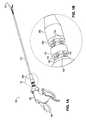
- FIGS. 1A and 2Ashow an articulatable tool 100 with an end effector 102 at its distal end and an end effector actuator 104 within a handle 106 at its proximal end:
- FIG. 1Ashows the tool in a neutral or non-articulated configuration
- FIG. 2Ashows the tool in an articulated position or configuration.
- FIG. 1Bshows detail (encircled in FIG. 1A ) of the proximal links of the tool and the proximal end-cap cover of a tension bearing member guide system.
- FIG. 2Bshows detail (encircled in FIG. 2A ) of the distal links of the tool and the distal end-cap cover of a tension bearing member guide system.
- Instrument 100may be used, e.g., in a laparoscopic procedure requiring grasping or cutting within a patient. Exemplary embodiments of the tool 100 may also be useful in endoscopic procedures, particularly when, as in some embodiments, the tool has a flexible shaft. Still other embodiments may be used for percutaneous procedures, such as a catheter. Still other embodiments include devices that are directed toward natural orifice transluminal endoscopic surgery (“NOTES”). Embodiments of the invention may include a wide variety of tools, some with medical or diagnostic purposes, and others that are applied to other types of tasks where the articulational capabilities of the tool provide benefit.
- NOTESnatural orifice transluminal endoscopic surgery
- Proximal articulation links 108 and 110extend distally from handle 106
- distal articulation links 112 and 114extend proximally from end effector 102
- Proximal link 108is a spindle and is connected to and moves with handle 106
- distal link 112is connected to and moves with end effector 102
- An elongated shaft 116is disposed between the proximal links and the distal links; in some embodiments the shaft is rigid, in other embodiments the shaft may be flexible.
- a set of tension bearing elements or control cables 118is attached to proximal link 108 , extends through proximal link 110 , shaft 116 and distal link 114 and is attached to distal link 112 , as shown in FIGS. 1A and 1B .
- a second set of tension bearing element or control cables 120is attached to proximal link 110 , extends through shaft 116 and is attached to distal link 114 .
- tension bearing elements other than cablesmay be used to connect corresponding links.
- the proximal and distal linkscan be connected by the tension bearing elements so as to move in the same direction with respect to the shaft (thereby providing a mirror image movement) or in opposite directions with respect to the shaft, depending on whether the tension bearing elements connect the corresponding links on the opposite sides or on the same sides of the links, respectively.
- the degree of relative movementcan be determined by the relative diameters of the cables' connections to corresponding links as well as through the use and specific design of bushings or spacer links separating the connected proximal and distal links.
- the cables' radial spacing on the proximal linksis about three times greater than their radial spacing on the distal links. This means that a movement of about 5° in a proximal link will cause a corresponding movement of about 15° in a distal link. Further details of these links are provided in US2005/0273085, which is hereby incorporated by this reference.
- the end effector 102is a pair of jaws. Actuation force is transmitted from end effector actuator 104 through a transmission that includes a linearly movable rod and a rotatable rod actuator (not shown). Other end effectors (surgical, diagnostic, etc.) and end effector actuators may be used with the articulating tool of this invention.
- the distal linksthemselves, can comprise an end effector, such as, for example, a retractor.
- the movable rodmay comprise any flexible material; in some embodiments Nitinol offers particular advantages as it is sufficiently flexible to accommodate articulation, and yet can still carry a compressive load sufficiently, for example, to be able to push open an end effector, such as a set of jaws.
- a series of proximal linksthemselves, can comprise a “handle” with no other rigid handle being provided.
- the proximal linksmay be formed into a particular shape which is emulated by a corresponding series of distal links. More details of such embodiments are provided in U.S. Pat. No. 7,090,637.
- FIG. 3shows an exploded view of certain proximal components of the articulating tool.
- the tension bearing elementshave been omitted for clarity.
- a double headed bushing 109is disposed between links 108 and 110
- another bushing 111is disposed between links 110 and a proximal end cap 300 .
- the interaction of bushings 109 and 111 with links 108 and 110 and with proximal end cap 300is described in more detail in U.S. 2005/0273084, U.S. 2006/0111209, and U.S. 2006/0111210. If the tension bearing cables 118 and 120 were shown in FIG. 3 as they are in FIGS.
- the proximal ends of the three cables 118would terminate in openings 1806 of link 108 , and the cables would pass through openings 1820 in link 110 and openings 304 in end cap 300 before entering shaft 116 .
- the proximal ends of three cables 120would terminate in openings 1822 of link 110 and would pass through openings 304 in proximal end cap 300 before entering shaft 116 .
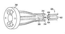
- a tapered end cap housing or cover 306is rigidly fixed to shaft 116 and provides a transition from end cap 300 to shaft 116 .
- FIGS. 4-6show details of end cap 300 .
- Cable openings 304lead to channels 308 extending distally from the end cap proximal face.
- Channels 308taper the radial distance between the cables within the proximal links 108 and 110 to a radial distribution suitable for the diameter of shaft 116 .
- Channels 308 depictedare in the form of grooves. In other embodiments (not shown) channels may be in a circumferentially enclosed form.
- An opening 310is provided for passage of the end effector actuation rod.
- a pair of pins 312connect the end cap 300 to the end cap housing, as explained below.
- a pair of tines 314connect with a shaft cable guide, as is also explained below.
- FIGS. 7-9show details of the end cap housing 306 .
- a pair of holes 320mate with the pins 312 of end cap 300 .
- Channels 322may be formed on the inner surface of housing 306 . These channels 322 line up with channels 308 of end cap 300 to help guide the cables as they transition from the proximal links into the shaft.
- a stepped distal opening 307surrounds the proximal end of the shaft 116 (as shown in FIG. 18 ).
- the proximal end cap 300 and end cap housing 306cooperate to provide a smooth transition between the cables' radial distribution within the shaft and their radial distribution on the proximal links.
- cables 118 and 120are constrained by the cooperating channels of end cap 300 and end cap housing 306 to limit any lateral movement of the cables.
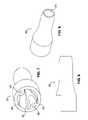
- FIGS. 10-12show details of a distal end cap 400 .
- distal end cap 400Like the proximal end cap, distal end cap 400 cooperates with a link bushing in the articulation mechanism and therefore has a socket 402 on its distal face and other features to interface with a bushing. Openings 404 line up with channels 406 to guide the tension bearing cables to the distal links.
- a pair of tines 408connect with the shaft cable guide, and a tab 409 indexes end cap 400 with the shaft.
- An opening 410permits passage of the end effector actuation rod.
- Some embodiments of the inventionhave a tension bearing element guide extending along part or all of the shaft.
- This guideis to maintain the relative position and orientation of the cables or other tension bearing members within the shaft. The guide also aids in the initial assembly of the tool, as discussed below.
- FIGS. 13-19show one embodiment of a shaft cable guide 420 and its interaction with proximal end cap 300 and distal end cap 400 .
- Guide 420has channels 422 in which the cables 118 and 120 or other tension bearing elements or elements may be disposed.
- Channels 422 depictedare in the form of grooves. In other embodiments ( FIG. 13B ) channels may be in a circumferentially enclosed form.
- the proximal ends of channels 422line up with channels 308 in proximal end cap 300 (as shown in FIG. 15 ) and the distal ends of channels 422 line up with channels 406 in distal end cap 400 (as shown in FIG. 16 ).
- tines 314 of proximal end cap 300can mate with the proximal ends of alignment channels 424 in guide 420 (as shown in FIG. 15 ), and tines 408 of distal end cap 400 can mate with the distal ends of alignment channels 424 (as shown in FIG. 16 ).
- Some embodimentsmay include a central channel or lumen 426 in guide 420 ( FIG. 13A ) that permits passage of an operable element such as the articulating tool's movable actuation rod 125 (as shown in FIG. 18 ), which further functions to prevent buckling of the actuation rod during its movement.
- the rod 125in some embodiments, in addition to being a tension bearing member may further be a compression bearing member.
- Central channel or lumen 426should be understood as being generally centrally-located, the channel need not be dead centrally located, and may be off-center.
- the guidemay include one or more additional channels or lumina 426 ′ and 427 , as seen in FIG. 13B , with four exemplary channels.
- channels 426 ′ and 427are generally centrally-disposed, in contrast to the more circumferentially disposed channels 422 or 422 ′.
- Such separate channels 426 ′ and 427may further accommodate other operable elements or components such as any type of tension bearing member or compression bearing member, wires, cables, hydraulic lines, vacuum lines, optical fibers, or any element useful in the operation of the distal portion of the tool. Separation of the central lumen into separate lumina provides for segregation of components or elements contained therein, and may facilitate the assembly of the tool, or the independence of the operation of the elements contained therein.
- tension member channels 422 ′ and alignment channel 424 ′may have a closed configuration.
- Guide 420 ′ of FIG. 13Bmay be used within a shaft tube as described below. Alternatively, in some embodiments, guide 420 ′ may itself serve as a shaft.
- tension member guide 420guides the cables or other tension bearing members axially along the shaft so that the cables' entry and exit points are at the same circumferential positions about the circumference of the shaft to provide movement of distal links that is opposite to the movement of their corresponding proximal links.
- movement of a proximal link to the right of the shaftwill cause movement of the corresponding distal link to the left of the shaft.
- the cables or other tension bearing elementsmust connect to the distal links at positions 180° opposite to their circumferential connection position on the corresponding proximal links.
- guide 420may be twisted 180° from proximal to distal end, as shown in FIG. 17 . It should be understood that guide 420 may also be twisted more or less than 180°, as desired.
- guide 420may be made of plastic through an extrusion process.
- the guidecan be formed with any desired amount axial twist, a twist of about 180° being typical, or the twist can be added during the assembly process, as described below. Further, other types of manufacturing processes known in the art may be used to form the guide, and in some embodiments it may be desirable to assemble multiple components into a whole to form the guide.
- proximal end cap housing 306may be rigidly attached to shaft 116 .
- the proximal end cap 300may also be rigidly attached to the proximal end of guide 420 by pressing tines 314 into the corresponding channels 424 in the guide and then gluing, if necessary.
- the proximal end cap/guide subassemblymay then be inserted into the proximal end of end cap housing 306 , as suggested by FIG. 19 , by inserting pins 312 into holes 320 in the end cap housing.
- the tines 408 of distal end cap 400may then be inserted into the distal ends of guide channels 424 .
- Distal end cap 400 and the distal end of guide 424may then be twisted 180° (or any other angle), if desired, before attaching by inserting tabs 409 into corresponding slots in the distal end of shaft 116 .
- the guide 420could be fixed to proximal end cap 300 , or guide 420 could be fixed to distal end cap 440 , or guide 420 could be inserted into the shaft 116 and then end caps fixed thereto, or tension members or cables could be first inserted into the guide, and the guide thence into the shaft. After assembly of the shaft, end cap housing, end caps, and tension bearing element guide, the cables and links may be assembled.
- the threading of cablesmay be performed by threading either the proximal ends or the distal ends forward in their respective appropriate direction. Further, any number of cable sets may be threaded during a threading procedure, in any order. The following detailed procedure is provided merely by way of an example wherein a single cable set is threaded in a particular direction. In the embodiment shown in FIGS. 1-20 , three cables 118 extend from distal link 112 to proximal link 108 , and three cables 120 extend from distal link 114 to proximal link 110 .
- Proximal ends of cables 120may be passed through openings 440 distributed about the circumference of distal link 114 such that they emerge from the openings on the proximal face of distal link 114 , as best seen in FIG. 20 .
- Proximal ends of cables 120may then be passed through openings 404 and channels 406 in distal end cap 400 , and into channels 422 in guide 420 .
- Channels 422guide the proximal ends of cables 120 to channels 308 and openings 304 in proximal end cap 300 , either with or without a twist, depending on the orientation of guide 420 .
- the proximal ends of cables 120then exit the proximal end cap 300 in the proper orientation for attachment of cables 120 and proximal link 110 to each other.
- attachment or anchoringmay be accomplished by one or more of a variety of attachment methods, such as by crimping, ultrasonic welding, gluing, or by applying set screws. Some examples of these attachment methods are further described below. While FIG. 20 shows an end effector 102 with jaws, it should be understood that other kinds of end effectors or no end effector may be used with the articulating tool of this invention.
- tension member guide 420By use of an embodiment of the tension member guide 420 through any of the methods as described above, or an equivalent method, it can be understood that the threading of cables from one end (proximal or distal) of the guide to the other end (or if already assembled within a shaft, from one end of to a shaft assembly to the other end) becomes quite simple and fool proof. Inserting one of a member into an end cap opening and thence into a guide channel assures the direction of that member end to the appropriate opening on at the opposite end cap opening.
- a benefit of the inventive guide and associated methodsrelates to the creation of a significant saving of time required for assembly of the tool.
- the distal ends of cables 120have enlarged portions that may be received within openings 440 as shown in FIG. 20 to prevent the distal ends from being pulled proximally through distal link 114 .
- the proximal ends of cables 118are passed through openings 442 distributed about distal link 112 , through distal link 114 , distal end cap 400 , down guide 420 through shaft 116 , through proximal end cap 300 and proximal link 110 , and are attached to proximal link 108 .
- Guide 420once again provides the proper position and orientation for cables 118 .
- FIGS. 21 and 22show details of one embodiment of a tension member attachment method.
- FIGS. 21 and 22are distal-looking perspective views of proximal link 110 before and after, respectively, being deformed by a crimping process.
- Holes 1820are provided through proximal link 110 for receiving cables 118 and holes 1822 are provided for receiving cables 120 (cables 118 and 120 can be seen in FIGS. 1 , 2 , 18 and 20 ).
- cables 118slidably pass through holes 1820 in proximal link 110 to terminate at proximal link 108 (as discussed below), and cables 120 terminate in holes 1822 of proximal link 110 .
- a portion 1824 of circumferential surface 1826may be inwardly deformed to collapse each hole 1822 ( FIG. 22 ) onto a cable 120 .
- Hole 1828 through the center of proximal link 110may be provided with an appropriately small or fitted diameter to constrain rod 125 from undesirable lateral movement, flexion, or buckling as it passes through link 110 .
- FIGS. 23 and 24show further details a crimp as applied to proximal link 108 which is integrated with a spindle element 117 .
- spindle element 117may be integrated with a spindle element 117 .
- Through holes 1806may be provided in link 108 for receiving the proximal ends of cables 118 (shown in FIGS. 1 , 2 , 18 and 20 ) that interconnect proximal link 108 with distal link 112 .
- cables 118shown in FIGS. 1 , 2 , 18 and 20
- FIGS. 1 , 2 , 18 and 20may be provided in link 108 for receiving the proximal ends of cables 118 (shown in FIGS. 1 , 2 , 18 and 20 ) that interconnect proximal link 108 with distal link 112 .
- only three of the six holes of proximal link 108are used (i.e. holes 1806 are used but holes 1807 are not).
- the proximal ends of cables 120may pass freely through the three vacant holes 1807 of proximal link 108 after being attached to proximal link 110 as described above so that all six cables can be cut at the same location proximal to link 108 .
- the proximal ends of cables 118may be secured within holes 1806 of link 108 by a crimping process, such as described above in relation to FIGS. 21 and 22 .
- a smaller crimping diemay be pressed radially inward from the circumferential surface 1808 of link 108 to deform the material adjacent to the cable end, leaving an indentation 1810 and securing the cable end from axial movement relative to link 108 .
- Links 108 , 110 , 112 , or 114may be made from a variety of materials suitable for the particular attachment process used, such as metals, plastics or ceramics.
- the side pockets for accommodating terminating cablesfor example opening 440 as shown FIG. 2B in the context of distal link 114 , may also be applied to cables that terminate proximal links.
- tension member guide systemmay be used in tools that are absent various features that may be associated with some articulatable instruments, such as handles, rotatability features, and dedicated end effectors.
- the tension member guide system or tool having such a systemmay have utility in other non-medical contexts as well.
Landscapes
- Health & Medical Sciences (AREA)
- Life Sciences & Earth Sciences (AREA)
- Surgery (AREA)
- Animal Behavior & Ethology (AREA)
- Public Health (AREA)
- Engineering & Computer Science (AREA)
- Biomedical Technology (AREA)
- Heart & Thoracic Surgery (AREA)
- Medical Informatics (AREA)
- Molecular Biology (AREA)
- Veterinary Medicine (AREA)
- General Health & Medical Sciences (AREA)
- Nuclear Medicine, Radiotherapy & Molecular Imaging (AREA)
- Physics & Mathematics (AREA)
- Biophysics (AREA)
- Optics & Photonics (AREA)
- Pathology (AREA)
- Radiology & Medical Imaging (AREA)
- Ophthalmology & Optometry (AREA)
- Surgical Instruments (AREA)
- Manipulator (AREA)
Abstract
Description
Claims (27)
Priority Applications (3)
| Application Number | Priority Date | Filing Date | Title |
|---|---|---|---|
| US11/787,607US9561045B2 (en) | 2006-06-13 | 2007-04-16 | Tool with rotation lock |
| US11/787,608US7862554B2 (en) | 2007-04-16 | 2007-04-16 | Articulating tool with improved tension member system |
| PCT/US2008/060540WO2008131046A2 (en) | 2007-04-16 | 2008-04-16 | Articulating tool with improved tension member system |
Applications Claiming Priority (1)
| Application Number | Priority Date | Filing Date | Title |
|---|---|---|---|
| US11/787,608US7862554B2 (en) | 2007-04-16 | 2007-04-16 | Articulating tool with improved tension member system |
Publications (2)
| Publication Number | Publication Date |
|---|---|
| US20080255421A1 US20080255421A1 (en) | 2008-10-16 |
| US7862554B2true US7862554B2 (en) | 2011-01-04 |
Family
ID=39854356
Family Applications (1)
| Application Number | Title | Priority Date | Filing Date |
|---|---|---|---|
| US11/787,608Active2029-08-26US7862554B2 (en) | 2006-06-13 | 2007-04-16 | Articulating tool with improved tension member system |
Country Status (2)
| Country | Link |
|---|---|
| US (1) | US7862554B2 (en) |
| WO (1) | WO2008131046A2 (en) |
Cited By (23)
| Publication number | Priority date | Publication date | Assignee | Title |
|---|---|---|---|---|
| US20110065990A1 (en)* | 2008-04-18 | 2011-03-17 | Marcel Antonius Elisabeth Verbeek | An instrument for endoscopic applications or the like |
| US20110087071A1 (en)* | 2004-11-23 | 2011-04-14 | Intuitive Surgical Operations, Inc. | Articulation sheath for flexible instruments |
| US20130345765A1 (en)* | 2012-06-20 | 2013-12-26 | Stryker Corporation | Systems and methods for off-axis tissue manipulation |
| US20140066951A1 (en)* | 2009-10-28 | 2014-03-06 | New York University | Cochlear implant with improved electrode array and controller |
| DE102015118641A1 (en) | 2015-10-30 | 2017-05-04 | Carl Zeiss Microscopy Gmbh | A device for optically examining a sample, a method for examining a sample, and a method for placing a device in a ready state |
| US20170325812A1 (en)* | 2008-08-18 | 2017-11-16 | Intuitive Surgical Operations, Inc. | Instrument With Multiple Articulation Locks |
| US9820766B2 (en) | 2013-12-04 | 2017-11-21 | Covidien Lp | Dual directional articulation hand instrument |
| US10405936B2 (en) | 2008-04-11 | 2019-09-10 | The Regents Of The University Of Michigan | Parallel kinematic mechanisms with decoupled rotational motions |
| US20200179651A1 (en)* | 2017-06-29 | 2020-06-11 | Deam Holding B.V. | Medical device with flexible tip |
| US10753439B2 (en) | 2015-04-03 | 2020-08-25 | The Regents Of The University Of Michigan | Tension management apparatus for cable-driven transmission |
| US10835229B2 (en) | 2013-08-14 | 2020-11-17 | Covidien Lp | Expandable balloon desufflation assembly |
| US10905464B2 (en) | 2018-12-28 | 2021-02-02 | Titan Medical, Inc. | Apparatus for providing access for a medical procedure |
| US10959797B2 (en) | 2015-10-05 | 2021-03-30 | Flexdex, Inc. | Medical devices having smoothly articulating multi-cluster joints |
| US10973499B2 (en)* | 2017-02-28 | 2021-04-13 | Boston Scientific Scimed, Inc. | Articulating needles and related methods of use |
| US11510687B2 (en) | 2018-11-16 | 2022-11-29 | Joint Preservation Innovations, LLC | Surgical rotary cutting tool including articulable head |
| US11844534B2 (en) | 2021-12-17 | 2023-12-19 | Joint Preservation Innovations, LLC | Articulating rotary cutting tool |
| US11896218B2 (en) | 2021-03-24 | 2024-02-13 | Cilag Gmbh International | Method of using a powered stapling device |
| US11896255B2 (en) | 2015-10-05 | 2024-02-13 | Flexdex, Inc. | End-effector jaw closure transmission systems for remote access tools |
| US11950966B2 (en) | 2020-06-02 | 2024-04-09 | Flexdex, Inc. | Surgical tool and assembly |
| US11957862B2 (en) | 2020-02-25 | 2024-04-16 | Titan Medical Inc. | Apparatus for providing instrument access through a surgical access device |
| US12089865B2 (en) | 2018-11-16 | 2024-09-17 | Joint Preservation Innovations, LLC | Surgical rotary cutting tool including articulable head |
| US12390293B2 (en) | 2016-02-25 | 2025-08-19 | Shorya Awtar | Parallel kinematic mechanisms with decoupled rotational motions |
| US12433664B2 (en) | 2021-05-03 | 2025-10-07 | Covidien Lp | Motor position control and methods for robotic assisted sealing instrument |
Families Citing this family (199)
| Publication number | Priority date | Publication date | Assignee | Title |
|---|---|---|---|---|
| US9060770B2 (en) | 2003-05-20 | 2015-06-23 | Ethicon Endo-Surgery, Inc. | Robotically-driven surgical instrument with E-beam driver |
| US20070084897A1 (en) | 2003-05-20 | 2007-04-19 | Shelton Frederick E Iv | Articulating surgical stapling instrument incorporating a two-piece e-beam firing mechanism |
| US8100824B2 (en) | 2003-05-23 | 2012-01-24 | Intuitive Surgical Operations, Inc. | Tool with articulation lock |
| US7410483B2 (en) | 2003-05-23 | 2008-08-12 | Novare Surgical Systems, Inc. | Hand-actuated device for remote manipulation of a grasping tool |
| US7828808B2 (en) | 2004-06-07 | 2010-11-09 | Novare Surgical Systems, Inc. | Link systems and articulation mechanisms for remote manipulation of surgical or diagnostic tools |
| US7678117B2 (en) | 2004-06-07 | 2010-03-16 | Novare Surgical Systems, Inc. | Articulating mechanism with flex-hinged links |
| US9072535B2 (en) | 2011-05-27 | 2015-07-07 | Ethicon Endo-Surgery, Inc. | Surgical stapling instruments with rotatable staple deployment arrangements |
| US11890012B2 (en) | 2004-07-28 | 2024-02-06 | Cilag Gmbh International | Staple cartridge comprising cartridge body and attached support |
| US11998198B2 (en) | 2004-07-28 | 2024-06-04 | Cilag Gmbh International | Surgical stapling instrument incorporating a two-piece E-beam firing mechanism |
| US11246590B2 (en) | 2005-08-31 | 2022-02-15 | Cilag Gmbh International | Staple cartridge including staple drivers having different unfired heights |
| US7669746B2 (en) | 2005-08-31 | 2010-03-02 | Ethicon Endo-Surgery, Inc. | Staple cartridges for forming staples having differing formed staple heights |
| US10159482B2 (en) | 2005-08-31 | 2018-12-25 | Ethicon Llc | Fastener cartridge assembly comprising a fixed anvil and different staple heights |
| US8708213B2 (en) | 2006-01-31 | 2014-04-29 | Ethicon Endo-Surgery, Inc. | Surgical instrument having a feedback system |
| US11793518B2 (en) | 2006-01-31 | 2023-10-24 | Cilag Gmbh International | Powered surgical instruments with firing system lockout arrangements |
| US20120292367A1 (en) | 2006-01-31 | 2012-11-22 | Ethicon Endo-Surgery, Inc. | Robotically-controlled end effector |
| US7845537B2 (en) | 2006-01-31 | 2010-12-07 | Ethicon Endo-Surgery, Inc. | Surgical instrument having recording capabilities |
| US8186555B2 (en) | 2006-01-31 | 2012-05-29 | Ethicon Endo-Surgery, Inc. | Motor-driven surgical cutting and fastening instrument with mechanical closure system |
| US8992422B2 (en) | 2006-03-23 | 2015-03-31 | Ethicon Endo-Surgery, Inc. | Robotically-controlled endoscopic accessory channel |
| US10568652B2 (en) | 2006-09-29 | 2020-02-25 | Ethicon Llc | Surgical staples having attached drivers of different heights and stapling instruments for deploying the same |
| US11980366B2 (en) | 2006-10-03 | 2024-05-14 | Cilag Gmbh International | Surgical instrument |
| US8632535B2 (en) | 2007-01-10 | 2014-01-21 | Ethicon Endo-Surgery, Inc. | Interlock and surgical instrument including same |
| US8684253B2 (en) | 2007-01-10 | 2014-04-01 | Ethicon Endo-Surgery, Inc. | Surgical instrument with wireless communication between a control unit of a robotic system and remote sensor |
| US20080169333A1 (en) | 2007-01-11 | 2008-07-17 | Shelton Frederick E | Surgical stapler end effector with tapered distal end |
| US11564682B2 (en) | 2007-06-04 | 2023-01-31 | Cilag Gmbh International | Surgical stapler device |
| US8931682B2 (en) | 2007-06-04 | 2015-01-13 | Ethicon Endo-Surgery, Inc. | Robotically-controlled shaft based rotary drive systems for surgical instruments |
| US11849941B2 (en) | 2007-06-29 | 2023-12-26 | Cilag Gmbh International | Staple cartridge having staple cavities extending at a transverse angle relative to a longitudinal cartridge axis |
| JP5410110B2 (en) | 2008-02-14 | 2014-02-05 | エシコン・エンド−サージェリィ・インコーポレイテッド | Surgical cutting / fixing instrument with RF electrode |
| US8573465B2 (en) | 2008-02-14 | 2013-11-05 | Ethicon Endo-Surgery, Inc. | Robotically-controlled surgical end effector system with rotary actuated closure systems |
| US8636736B2 (en) | 2008-02-14 | 2014-01-28 | Ethicon Endo-Surgery, Inc. | Motorized surgical cutting and fastening instrument |
| US11986183B2 (en) | 2008-02-14 | 2024-05-21 | Cilag Gmbh International | Surgical cutting and fastening instrument comprising a plurality of sensors to measure an electrical parameter |
| US9585657B2 (en) | 2008-02-15 | 2017-03-07 | Ethicon Endo-Surgery, Llc | Actuator for releasing a layer of material from a surgical end effector |
| US20110040308A1 (en) | 2008-06-13 | 2011-02-17 | Ramiro Cabrera | Endoscopic Stitching Devices |
| US8628545B2 (en)* | 2008-06-13 | 2014-01-14 | Covidien Lp | Endoscopic stitching devices |
| US9204923B2 (en) | 2008-07-16 | 2015-12-08 | Intuitive Surgical Operations, Inc. | Medical instrument electronically energized using drive cables |
| US8210411B2 (en) | 2008-09-23 | 2012-07-03 | Ethicon Endo-Surgery, Inc. | Motor-driven surgical cutting instrument |
| US9005230B2 (en) | 2008-09-23 | 2015-04-14 | Ethicon Endo-Surgery, Inc. | Motorized surgical instrument |
| US11648005B2 (en) | 2008-09-23 | 2023-05-16 | Cilag Gmbh International | Robotically-controlled motorized surgical instrument with an end effector |
| US9386983B2 (en) | 2008-09-23 | 2016-07-12 | Ethicon Endo-Surgery, Llc | Robotically-controlled motorized surgical instrument |
| US8608045B2 (en) | 2008-10-10 | 2013-12-17 | Ethicon Endo-Sugery, Inc. | Powered surgical cutting and stapling apparatus with manually retractable firing system |
| US20110022078A1 (en) | 2009-07-23 | 2011-01-27 | Cameron Dale Hinman | Articulating mechanism |
| HU229773B1 (en)* | 2009-09-02 | 2014-06-30 | A tool for surgical intervention | |
| US8220688B2 (en) | 2009-12-24 | 2012-07-17 | Ethicon Endo-Surgery, Inc. | Motor-driven surgical cutting instrument with electric actuator directional control assembly |
| ES2662543T3 (en) | 2010-01-26 | 2018-04-06 | Artack Medical (2013) Ltd. | Articulated medical instrument |
| US9386988B2 (en) | 2010-09-30 | 2016-07-12 | Ethicon End-Surgery, LLC | Retainer assembly including a tissue thickness compensator |
| US11925354B2 (en) | 2010-09-30 | 2024-03-12 | Cilag Gmbh International | Staple cartridge comprising staples positioned within a compressible portion thereof |
| US9788834B2 (en) | 2010-09-30 | 2017-10-17 | Ethicon Llc | Layer comprising deployable attachment members |
| US10945731B2 (en) | 2010-09-30 | 2021-03-16 | Ethicon Llc | Tissue thickness compensator comprising controlled release and expansion |
| US12213666B2 (en) | 2010-09-30 | 2025-02-04 | Cilag Gmbh International | Tissue thickness compensator comprising layers |
| US9629814B2 (en) | 2010-09-30 | 2017-04-25 | Ethicon Endo-Surgery, Llc | Tissue thickness compensator configured to redistribute compressive forces |
| US11812965B2 (en) | 2010-09-30 | 2023-11-14 | Cilag Gmbh International | Layer of material for a surgical end effector |
| WO2012074564A1 (en)* | 2010-12-02 | 2012-06-07 | Freehand Endoscopic Devices, Inc. | Surgical tool |
| AU2012250197B2 (en) | 2011-04-29 | 2017-08-10 | Ethicon Endo-Surgery, Inc. | Staple cartridge comprising staples positioned within a compressible portion thereof |
| US9161771B2 (en)* | 2011-05-13 | 2015-10-20 | Intuitive Surgical Operations Inc. | Medical instrument with snake wrist structure |
| US11207064B2 (en) | 2011-05-27 | 2021-12-28 | Cilag Gmbh International | Automated end effector component reloading system for use with a robotic system |
| MX358135B (en) | 2012-03-28 | 2018-08-06 | Ethicon Endo Surgery Inc | Tissue thickness compensator comprising a plurality of layers. |
| BR112014024098B1 (en) | 2012-03-28 | 2021-05-25 | Ethicon Endo-Surgery, Inc. | staple cartridge |
| US9211134B2 (en) | 2012-04-09 | 2015-12-15 | Carefusion 2200, Inc. | Wrist assembly for articulating laparoscopic surgical instruments |
| US9101358B2 (en) | 2012-06-15 | 2015-08-11 | Ethicon Endo-Surgery, Inc. | Articulatable surgical instrument comprising a firing drive |
| US20140001231A1 (en) | 2012-06-28 | 2014-01-02 | Ethicon Endo-Surgery, Inc. | Firing system lockout arrangements for surgical instruments |
| US9289256B2 (en) | 2012-06-28 | 2016-03-22 | Ethicon Endo-Surgery, Llc | Surgical end effectors having angled tissue-contacting surfaces |
| US12383267B2 (en) | 2012-06-28 | 2025-08-12 | Cilag Gmbh International | Robotically powered surgical device with manually-actuatable reversing system |
| US20140012075A1 (en)* | 2012-07-09 | 2014-01-09 | Gyrus Acmi, Inc., D.B.A. Olympus Surgical Technologies America | Sinus endoscope |
| RU2672520C2 (en) | 2013-03-01 | 2018-11-15 | Этикон Эндо-Серджери, Инк. | Hingedly turnable surgical instruments with conducting ways for signal transfer |
| BR112015021082B1 (en) | 2013-03-01 | 2022-05-10 | Ethicon Endo-Surgery, Inc | surgical instrument |
| US9629629B2 (en) | 2013-03-14 | 2017-04-25 | Ethicon Endo-Surgey, LLC | Control systems for surgical instruments |
| BR112015026109B1 (en) | 2013-04-16 | 2022-02-22 | Ethicon Endo-Surgery, Inc | surgical instrument |
| US9775609B2 (en) | 2013-08-23 | 2017-10-03 | Ethicon Llc | Tamper proof circuit for surgical instrument battery pack |
| US12232723B2 (en) | 2014-03-26 | 2025-02-25 | Cilag Gmbh International | Systems and methods for controlling a segmented circuit |
| US10013049B2 (en) | 2014-03-26 | 2018-07-03 | Ethicon Llc | Power management through sleep options of segmented circuit and wake up control |
| US20150272580A1 (en) | 2014-03-26 | 2015-10-01 | Ethicon Endo-Surgery, Inc. | Verification of number of battery exchanges/procedure count |
| US20150297225A1 (en) | 2014-04-16 | 2015-10-22 | Ethicon Endo-Surgery, Inc. | Fastener cartridges including extensions having different configurations |
| CN106456176B (en) | 2014-04-16 | 2019-06-28 | 伊西康内外科有限责任公司 | Fastener Cartridge Including Extensions With Different Configurations |
| US10327764B2 (en) | 2014-09-26 | 2019-06-25 | Ethicon Llc | Method for creating a flexible staple line |
| BR112016023825B1 (en) | 2014-04-16 | 2022-08-02 | Ethicon Endo-Surgery, Llc | STAPLE CARTRIDGE FOR USE WITH A SURGICAL STAPLER AND STAPLE CARTRIDGE FOR USE WITH A SURGICAL INSTRUMENT |
| CN106456159B (en) | 2014-04-16 | 2019-03-08 | 伊西康内外科有限责任公司 | Fastener Cartridge Assembly and Nail Retainer Cover Arrangement |
| DE102014010181B4 (en)* | 2014-07-09 | 2021-03-11 | Schölly Fiberoptic GmbH | Manipulation and / or investigation instrument |
| BR112017004361B1 (en) | 2014-09-05 | 2023-04-11 | Ethicon Llc | ELECTRONIC SYSTEM FOR A SURGICAL INSTRUMENT |
| US11311294B2 (en) | 2014-09-05 | 2022-04-26 | Cilag Gmbh International | Powered medical device including measurement of closure state of jaws |
| US10135242B2 (en) | 2014-09-05 | 2018-11-20 | Ethicon Llc | Smart cartridge wake up operation and data retention |
| US10105142B2 (en) | 2014-09-18 | 2018-10-23 | Ethicon Llc | Surgical stapler with plurality of cutting elements |
| US11523821B2 (en) | 2014-09-26 | 2022-12-13 | Cilag Gmbh International | Method for creating a flexible staple line |
| US9924944B2 (en) | 2014-10-16 | 2018-03-27 | Ethicon Llc | Staple cartridge comprising an adjunct material |
| US10517594B2 (en) | 2014-10-29 | 2019-12-31 | Ethicon Llc | Cartridge assemblies for surgical staplers |
| US10736636B2 (en) | 2014-12-10 | 2020-08-11 | Ethicon Llc | Articulatable surgical instrument system |
| MX389118B (en) | 2014-12-18 | 2025-03-20 | Ethicon Llc | SURGICAL INSTRUMENT WITH AN ANVIL THAT CAN BE SELECTIVELY MOVED ON A DISCRETE, NON-MOBILE AXIS RELATIVE TO A STAPLE CARTRIDGE. |
| US10085748B2 (en) | 2014-12-18 | 2018-10-02 | Ethicon Llc | Locking arrangements for detachable shaft assemblies with articulatable surgical end effectors |
| US9987000B2 (en) | 2014-12-18 | 2018-06-05 | Ethicon Llc | Surgical instrument assembly comprising a flexible articulation system |
| US11154301B2 (en) | 2015-02-27 | 2021-10-26 | Cilag Gmbh International | Modular stapling assembly |
| US10441279B2 (en) | 2015-03-06 | 2019-10-15 | Ethicon Llc | Multiple level thresholds to modify operation of powered surgical instruments |
| US10433844B2 (en) | 2015-03-31 | 2019-10-08 | Ethicon Llc | Surgical instrument with selectively disengageable threaded drive systems |
| US10105139B2 (en) | 2015-09-23 | 2018-10-23 | Ethicon Llc | Surgical stapler having downstream current-based motor control |
| US10299878B2 (en) | 2015-09-25 | 2019-05-28 | Ethicon Llc | Implantable adjunct systems for determining adjunct skew |
| US11890015B2 (en) | 2015-09-30 | 2024-02-06 | Cilag Gmbh International | Compressible adjunct with crossing spacer fibers |
| US10433846B2 (en) | 2015-09-30 | 2019-10-08 | Ethicon Llc | Compressible adjunct with crossing spacer fibers |
| US10478188B2 (en) | 2015-09-30 | 2019-11-19 | Ethicon Llc | Implantable layer comprising a constricted configuration |
| US10265068B2 (en) | 2015-12-30 | 2019-04-23 | Ethicon Llc | Surgical instruments with separable motors and motor control circuits |
| US10292704B2 (en) | 2015-12-30 | 2019-05-21 | Ethicon Llc | Mechanisms for compensating for battery pack failure in powered surgical instruments |
| US11213293B2 (en) | 2016-02-09 | 2022-01-04 | Cilag Gmbh International | Articulatable surgical instruments with single articulation link arrangements |
| US10448948B2 (en) | 2016-02-12 | 2019-10-22 | Ethicon Llc | Mechanisms for compensating for drivetrain failure in powered surgical instruments |
| DE102016105767B4 (en)* | 2016-03-30 | 2020-10-01 | Digital Endoscopy Gmbh | Endoscope control device and endoscope |
| US10828028B2 (en) | 2016-04-15 | 2020-11-10 | Ethicon Llc | Surgical instrument with multiple program responses during a firing motion |
| US10357247B2 (en) | 2016-04-15 | 2019-07-23 | Ethicon Llc | Surgical instrument with multiple program responses during a firing motion |
| US20170296173A1 (en) | 2016-04-18 | 2017-10-19 | Ethicon Endo-Surgery, Llc | Method for operating a surgical instrument |
| US10500000B2 (en) | 2016-08-16 | 2019-12-10 | Ethicon Llc | Surgical tool with manual control of end effector jaws |
| CN106236269B (en)* | 2016-08-31 | 2018-09-04 | 北京术锐技术有限公司 | A kind of multivariant flexible operation tool |
| US20180168625A1 (en) | 2016-12-21 | 2018-06-21 | Ethicon Endo-Surgery, Llc | Surgical stapling instruments with smart staple cartridges |
| US11090048B2 (en) | 2016-12-21 | 2021-08-17 | Cilag Gmbh International | Method for resetting a fuse of a surgical instrument shaft |
| US10813638B2 (en) | 2016-12-21 | 2020-10-27 | Ethicon Llc | Surgical end effectors with expandable tissue stop arrangements |
| JP7010957B2 (en) | 2016-12-21 | 2022-01-26 | エシコン エルエルシー | Shaft assembly with lockout |
| US10973516B2 (en) | 2016-12-21 | 2021-04-13 | Ethicon Llc | Surgical end effectors and adaptable firing members therefor |
| JP7010956B2 (en) | 2016-12-21 | 2022-01-26 | エシコン エルエルシー | How to staple tissue |
| US10881399B2 (en) | 2017-06-20 | 2021-01-05 | Ethicon Llc | Techniques for adaptive control of motor velocity of a surgical stapling and cutting instrument |
| US10307170B2 (en) | 2017-06-20 | 2019-06-04 | Ethicon Llc | Method for closed loop control of motor velocity of a surgical stapling and cutting instrument |
| US10779820B2 (en) | 2017-06-20 | 2020-09-22 | Ethicon Llc | Systems and methods for controlling motor speed according to user input for a surgical instrument |
| EP3420947B1 (en) | 2017-06-28 | 2022-05-25 | Cilag GmbH International | Surgical instrument comprising selectively actuatable rotatable couplers |
| US11484310B2 (en) | 2017-06-28 | 2022-11-01 | Cilag Gmbh International | Surgical instrument comprising a shaft including a closure tube profile |
| USD906355S1 (en) | 2017-06-28 | 2020-12-29 | Ethicon Llc | Display screen or portion thereof with a graphical user interface for a surgical instrument |
| US10932772B2 (en) | 2017-06-29 | 2021-03-02 | Ethicon Llc | Methods for closed loop velocity control for robotic surgical instrument |
| US11944300B2 (en) | 2017-08-03 | 2024-04-02 | Cilag Gmbh International | Method for operating a surgical system bailout |
| US11974742B2 (en) | 2017-08-03 | 2024-05-07 | Cilag Gmbh International | Surgical system comprising an articulation bailout |
| US11134944B2 (en) | 2017-10-30 | 2021-10-05 | Cilag Gmbh International | Surgical stapler knife motion controls |
| US10842490B2 (en) | 2017-10-31 | 2020-11-24 | Ethicon Llc | Cartridge body design with force reduction based on firing completion |
| WO2019118336A1 (en) | 2017-12-14 | 2019-06-20 | Intuitive Surgical Operations, Inc. | Medical tools having tension bands |
| US10779826B2 (en) | 2017-12-15 | 2020-09-22 | Ethicon Llc | Methods of operating surgical end effectors |
| US10835330B2 (en) | 2017-12-19 | 2020-11-17 | Ethicon Llc | Method for determining the position of a rotatable jaw of a surgical instrument attachment assembly |
| US12336705B2 (en) | 2017-12-21 | 2025-06-24 | Cilag Gmbh International | Continuous use self-propelled stapling instrument |
| US11179151B2 (en) | 2017-12-21 | 2021-11-23 | Cilag Gmbh International | Surgical instrument comprising a display |
| US11992286B2 (en) | 2018-03-07 | 2024-05-28 | Intuitive Surgical Operations, Inc. | Low-friction medical tools having roller-assisted tension members |
| US12082900B2 (en) | 2018-03-07 | 2024-09-10 | Intuitive Surgical Operations, Inc. | Low-friction, small profile medical tools having easy-to-assemble components |
| EP3761897A4 (en) | 2018-03-07 | 2021-11-24 | Intuitive Surgical Operations, Inc. | LOW-FRICTION MEDICAL TOOLS WITH SMALL PROFILE AND ASSEMBLY-FRIENDLY COMPONENTS |
| US11197665B2 (en) | 2018-08-06 | 2021-12-14 | Covidien Lp | Needle reload device for use with endostitch device |
| US20200054321A1 (en) | 2018-08-20 | 2020-02-20 | Ethicon Llc | Surgical instruments with progressive jaw closure arrangements |
| US11291440B2 (en) | 2018-08-20 | 2022-04-05 | Cilag Gmbh International | Method for operating a powered articulatable surgical instrument |
| US11207065B2 (en) | 2018-08-20 | 2021-12-28 | Cilag Gmbh International | Method for fabricating surgical stapler anvils |
| US11696761B2 (en) | 2019-03-25 | 2023-07-11 | Cilag Gmbh International | Firing drive arrangements for surgical systems |
| US20200345359A1 (en) | 2019-04-30 | 2020-11-05 | Ethicon Llc | Tissue stop for a surgical instrument |
| US11903581B2 (en) | 2019-04-30 | 2024-02-20 | Cilag Gmbh International | Methods for stapling tissue using a surgical instrument |
| US12004740B2 (en) | 2019-06-28 | 2024-06-11 | Cilag Gmbh International | Surgical stapling system having an information decryption protocol |
| US11684434B2 (en) | 2019-06-28 | 2023-06-27 | Cilag Gmbh International | Surgical RFID assemblies for instrument operational setting control |
| US11771419B2 (en) | 2019-06-28 | 2023-10-03 | Cilag Gmbh International | Packaging for a replaceable component of a surgical stapling system |
| US11660163B2 (en) | 2019-06-28 | 2023-05-30 | Cilag Gmbh International | Surgical system with RFID tags for updating motor assembly parameters |
| US11241235B2 (en) | 2019-06-28 | 2022-02-08 | Cilag Gmbh International | Method of using multiple RFID chips with a surgical assembly |
| DE102019121088A1 (en)* | 2019-08-05 | 2021-02-11 | Karl Storz Se & Co. Kg | MEDICAL INSTRUMENT |
| US11701111B2 (en) | 2019-12-19 | 2023-07-18 | Cilag Gmbh International | Method for operating a surgical stapling instrument |
| US12035913B2 (en) | 2019-12-19 | 2024-07-16 | Cilag Gmbh International | Staple cartridge comprising a deployable knife |
| US11844520B2 (en) | 2019-12-19 | 2023-12-19 | Cilag Gmbh International | Staple cartridge comprising driver retention members |
| US11871925B2 (en) | 2020-07-28 | 2024-01-16 | Cilag Gmbh International | Surgical instruments with dual spherical articulation joint arrangements |
| US11931025B2 (en) | 2020-10-29 | 2024-03-19 | Cilag Gmbh International | Surgical instrument comprising a releasable closure drive lock |
| US11844518B2 (en) | 2020-10-29 | 2023-12-19 | Cilag Gmbh International | Method for operating a surgical instrument |
| US12053175B2 (en) | 2020-10-29 | 2024-08-06 | Cilag Gmbh International | Surgical instrument comprising a stowed closure actuator stop |
| US11779330B2 (en) | 2020-10-29 | 2023-10-10 | Cilag Gmbh International | Surgical instrument comprising a jaw alignment system |
| US11896217B2 (en) | 2020-10-29 | 2024-02-13 | Cilag Gmbh International | Surgical instrument comprising an articulation lock |
| USD1013170S1 (en) | 2020-10-29 | 2024-01-30 | Cilag Gmbh International | Surgical instrument assembly |
| US11890010B2 (en) | 2020-12-02 | 2024-02-06 | Cllag GmbH International | Dual-sided reinforced reload for surgical instruments |
| US11849943B2 (en) | 2020-12-02 | 2023-12-26 | Cilag Gmbh International | Surgical instrument with cartridge release mechanisms |
| US11737751B2 (en) | 2020-12-02 | 2023-08-29 | Cilag Gmbh International | Devices and methods of managing energy dissipated within sterile barriers of surgical instrument housings |
| US11653920B2 (en) | 2020-12-02 | 2023-05-23 | Cilag Gmbh International | Powered surgical instruments with communication interfaces through sterile barrier |
| US11944296B2 (en) | 2020-12-02 | 2024-04-02 | Cilag Gmbh International | Powered surgical instruments with external connectors |
| US11653915B2 (en) | 2020-12-02 | 2023-05-23 | Cilag Gmbh International | Surgical instruments with sled location detection and adjustment features |
| US11744581B2 (en) | 2020-12-02 | 2023-09-05 | Cilag Gmbh International | Powered surgical instruments with multi-phase tissue treatment |
| US11749877B2 (en) | 2021-02-26 | 2023-09-05 | Cilag Gmbh International | Stapling instrument comprising a signal antenna |
| US11701113B2 (en) | 2021-02-26 | 2023-07-18 | Cilag Gmbh International | Stapling instrument comprising a separate power antenna and a data transfer antenna |
| US11751869B2 (en) | 2021-02-26 | 2023-09-12 | Cilag Gmbh International | Monitoring of multiple sensors over time to detect moving characteristics of tissue |
| US11744583B2 (en) | 2021-02-26 | 2023-09-05 | Cilag Gmbh International | Distal communication array to tune frequency of RF systems |
| US12108951B2 (en) | 2021-02-26 | 2024-10-08 | Cilag Gmbh International | Staple cartridge comprising a sensing array and a temperature control system |
| US11925349B2 (en) | 2021-02-26 | 2024-03-12 | Cilag Gmbh International | Adjustment to transfer parameters to improve available power |
| US11696757B2 (en) | 2021-02-26 | 2023-07-11 | Cilag Gmbh International | Monitoring of internal systems to detect and track cartridge motion status |
| US11730473B2 (en) | 2021-02-26 | 2023-08-22 | Cilag Gmbh International | Monitoring of manufacturing life-cycle |
| US11812964B2 (en) | 2021-02-26 | 2023-11-14 | Cilag Gmbh International | Staple cartridge comprising a power management circuit |
| US12324580B2 (en) | 2021-02-26 | 2025-06-10 | Cilag Gmbh International | Method of powering and communicating with a staple cartridge |
| US11980362B2 (en) | 2021-02-26 | 2024-05-14 | Cilag Gmbh International | Surgical instrument system comprising a power transfer coil |
| US11950777B2 (en) | 2021-02-26 | 2024-04-09 | Cilag Gmbh International | Staple cartridge comprising an information access control system |
| US11793514B2 (en) | 2021-02-26 | 2023-10-24 | Cilag Gmbh International | Staple cartridge comprising sensor array which may be embedded in cartridge body |
| US11723657B2 (en) | 2021-02-26 | 2023-08-15 | Cilag Gmbh International | Adjustable communication based on available bandwidth and power capacity |
| US11826042B2 (en) | 2021-03-22 | 2023-11-28 | Cilag Gmbh International | Surgical instrument comprising a firing drive including a selectable leverage mechanism |
| US11759202B2 (en) | 2021-03-22 | 2023-09-19 | Cilag Gmbh International | Staple cartridge comprising an implantable layer |
| US11826012B2 (en) | 2021-03-22 | 2023-11-28 | Cilag Gmbh International | Stapling instrument comprising a pulsed motor-driven firing rack |
| US11737749B2 (en) | 2021-03-22 | 2023-08-29 | Cilag Gmbh International | Surgical stapling instrument comprising a retraction system |
| US11723658B2 (en) | 2021-03-22 | 2023-08-15 | Cilag Gmbh International | Staple cartridge comprising a firing lockout |
| US11717291B2 (en) | 2021-03-22 | 2023-08-08 | Cilag Gmbh International | Staple cartridge comprising staples configured to apply different tissue compression |
| US11806011B2 (en) | 2021-03-22 | 2023-11-07 | Cilag Gmbh International | Stapling instrument comprising tissue compression systems |
| US11832816B2 (en) | 2021-03-24 | 2023-12-05 | Cilag Gmbh International | Surgical stapling assembly comprising nonplanar staples and planar staples |
| US11857183B2 (en) | 2021-03-24 | 2024-01-02 | Cilag Gmbh International | Stapling assembly components having metal substrates and plastic bodies |
| US11849945B2 (en) | 2021-03-24 | 2023-12-26 | Cilag Gmbh International | Rotary-driven surgical stapling assembly comprising eccentrically driven firing member |
| US11896219B2 (en) | 2021-03-24 | 2024-02-13 | Cilag Gmbh International | Mating features between drivers and underside of a cartridge deck |
| US11793516B2 (en) | 2021-03-24 | 2023-10-24 | Cilag Gmbh International | Surgical staple cartridge comprising longitudinal support beam |
| US12102323B2 (en) | 2021-03-24 | 2024-10-01 | Cilag Gmbh International | Rotary-driven surgical stapling assembly comprising a floatable component |
| US11744603B2 (en) | 2021-03-24 | 2023-09-05 | Cilag Gmbh International | Multi-axis pivot joints for surgical instruments and methods for manufacturing same |
| US11903582B2 (en) | 2021-03-24 | 2024-02-20 | Cilag Gmbh International | Leveraging surfaces for cartridge installation |
| US11849944B2 (en) | 2021-03-24 | 2023-12-26 | Cilag Gmbh International | Drivers for fastener cartridge assemblies having rotary drive screws |
| US11786243B2 (en) | 2021-03-24 | 2023-10-17 | Cilag Gmbh International | Firing members having flexible portions for adapting to a load during a surgical firing stroke |
| US11786239B2 (en) | 2021-03-24 | 2023-10-17 | Cilag Gmbh International | Surgical instrument articulation joint arrangements comprising multiple moving linkage features |
| US11944336B2 (en)* | 2021-03-24 | 2024-04-02 | Cilag Gmbh International | Joint arrangements for multi-planar alignment and support of operational drive shafts in articulatable surgical instruments |
| US11826047B2 (en) | 2021-05-28 | 2023-11-28 | Cilag Gmbh International | Stapling instrument comprising jaw mounts |
| USD1034977S1 (en) | 2021-07-23 | 2024-07-09 | Ipg Photonics Corporation | Control handle grip for a catheter |
| US11980363B2 (en) | 2021-10-18 | 2024-05-14 | Cilag Gmbh International | Row-to-row staple array variations |
| US12432790B2 (en) | 2021-10-28 | 2025-09-30 | Cilag Gmbh International | Method and device for transmitting UART communications over a security short range wireless communication |
| US11937816B2 (en) | 2021-10-28 | 2024-03-26 | Cilag Gmbh International | Electrical lead arrangements for surgical instruments |
| US12089841B2 (en) | 2021-10-28 | 2024-09-17 | Cilag CmbH International | Staple cartridge identification systems |
Citations (149)
| Publication number | Priority date | Publication date | Assignee | Title |
|---|---|---|---|---|
| US1820463A (en) | 1931-04-30 | 1931-08-25 | Otto G Klein | Clinker tongs |
| US3060972A (en) | 1957-08-22 | 1962-10-30 | Bausch & Lomb | Flexible tube structures |
| US3071161A (en) | 1960-05-16 | 1963-01-01 | Bausch & Lomb | Bidirectionally flexible segmented tube |
| US3190286A (en) | 1961-10-31 | 1965-06-22 | Bausch & Lomb | Flexible viewing probe for endoscopic use |
| US3557780A (en) | 1967-04-20 | 1971-01-26 | Olympus Optical Co | Mechanism for controlling flexure of endoscope |
| US3605725A (en) | 1968-08-07 | 1971-09-20 | Medi Tech Inc | Controlled motion devices |
| US4466649A (en) | 1981-05-30 | 1984-08-21 | Tomy Kogyo Co., Inc. | Extendable hand amusement device |
| US4489826A (en) | 1982-02-05 | 1984-12-25 | Philip Dubson | Adjustable apparatus |
| EP0165718A2 (en) | 1984-05-22 | 1985-12-27 | Pilkington Medical Systems Limited (formely Minvade Limited) | Endoscopes |
| US4580551A (en) | 1984-11-02 | 1986-04-08 | Warner-Lambert Technologies, Inc. | Flexible plastic tube for endoscopes and the like |
| US4700693A (en) | 1985-12-09 | 1987-10-20 | Welch Allyn, Inc. | Endoscope steering section |
| US4763669A (en) | 1986-01-09 | 1988-08-16 | Jaeger John C | Surgical instrument with adjustable angle of operation |
| US4790294A (en) | 1987-07-28 | 1988-12-13 | Welch Allyn, Inc. | Ball-and-socket bead endoscope steering section |
| US4834761A (en) | 1985-05-09 | 1989-05-30 | Walters David A | Robotic multiple-jointed digit control system |
| US4854626A (en) | 1988-01-26 | 1989-08-08 | Duke Roger S | Fish retrieving tool |
| US4880015A (en) | 1988-06-03 | 1989-11-14 | Nierman David M | Biopsy forceps |
| US4984951A (en) | 1988-01-20 | 1991-01-15 | The Board Of Trustees Of The Leland Stanford Junior University | Mechanical prehensor |
| US5174276A (en) | 1988-11-18 | 1992-12-29 | Hillway Surgical Limited | Endoscope device for applying an aneurysm clip |
| US5257618A (en) | 1990-11-06 | 1993-11-02 | Fuji Photo Optical Co., Ltd. | Endoscope |
| US5271381A (en) | 1991-11-18 | 1993-12-21 | Vision Sciences, Inc. | Vertebrae for a bending section of an endoscope |
| US5273026A (en) | 1992-03-06 | 1993-12-28 | Wilk Peter J | Retractor and associated method for use in laparoscopic surgery |
| US5286228A (en) | 1992-11-23 | 1994-02-15 | C. J. Associates, Ltd. | Toy mechanical hand |
| US5297443A (en) | 1992-07-07 | 1994-03-29 | Wentz John D | Flexible positioning appendage |
| US5314424A (en) | 1992-04-06 | 1994-05-24 | United States Surgical Corporation | Surgical instrument locking mechanism |
| EP0598618A2 (en) | 1992-11-19 | 1994-05-25 | Ethicon, Inc. | Intraluminal manipulator |
| US5322064A (en) | 1991-02-15 | 1994-06-21 | Lundquist Ingemar H | Torquable catheter and method |
| US5325845A (en) | 1992-06-08 | 1994-07-05 | Adair Edwin Lloyd | Steerable sheath for use with selected removable optical catheter |
| US5330502A (en) | 1992-10-09 | 1994-07-19 | Ethicon, Inc. | Rotational endoscopic mechanism with jointed drive mechanism |
| JPH06262549A (en) | 1993-03-04 | 1994-09-20 | Daum Gmbh | Manipulator for surgery |
| US5354162A (en) | 1991-02-26 | 1994-10-11 | Rutgers University | Actuator system for providing force feedback to portable master support |
| US5381782A (en) | 1992-01-09 | 1995-01-17 | Spectrum Medsystems Corporation | Bi-directional and multi-directional miniscopes |
| US5403342A (en) | 1992-04-23 | 1995-04-04 | United States Surgical Corporation | Articulating endoscopic surgical apparatus |
| US5405344A (en) | 1993-09-30 | 1995-04-11 | Ethicon, Inc. | Articulable socket joint assembly for an endoscopic instrument for surgical fastner track therefor |
| US5441494A (en) | 1993-07-29 | 1995-08-15 | Ethicon, Inc. | Manipulable hand for laparoscopy |
| US5454827A (en) | 1994-05-24 | 1995-10-03 | Aust; Gilbert M. | Surgical instrument |
| US5476479A (en) | 1991-09-26 | 1995-12-19 | United States Surgical Corporation | Handle for endoscopic surgical instruments and jaw structure |
| US5486154A (en) | 1993-06-08 | 1996-01-23 | Kelleher; Brian S. | Endoscope |
| US5490819A (en) | 1991-08-05 | 1996-02-13 | United States Surgical Corporation | Articulating endoscopic surgical apparatus |
| US5498256A (en) | 1993-05-28 | 1996-03-12 | Snowden-Pencer, Inc. | Surgical instrument handle |
| US5513827A (en) | 1993-07-26 | 1996-05-07 | Karlin Technology, Inc. | Gooseneck surgical instrument holder |
| US5520678A (en) | 1993-11-30 | 1996-05-28 | Richard Wolf Gmbh | Manipulator arm with proximal and distal control balls |
| US5522788A (en) | 1994-10-26 | 1996-06-04 | Kuzmak; Lubomyr I. | Finger-like laparoscopic blunt dissector device |
| US5549636A (en) | 1994-10-05 | 1996-08-27 | Li Medical Technologies Inc. | Surgical grasper with articulated fingers |
| US5562699A (en) | 1994-03-30 | 1996-10-08 | Richard Wolf Gmbh | Forceps |
| US5570919A (en) | 1995-06-26 | 1996-11-05 | Eusebe; Frantz-Lee | Remote grapple |
| US5599151A (en) | 1993-03-04 | 1997-02-04 | Daum Gmbh | Surgical manipulator |
| US5609601A (en) | 1994-09-23 | 1997-03-11 | United States Surgical Corporation | Endoscopic surgical apparatus with rotation lock |
| US5620415A (en) | 1993-01-29 | 1997-04-15 | Smith & Dyonics, Inc. | Surgical instrument |
| US5624398A (en) | 1996-02-08 | 1997-04-29 | Symbiosis Corporation | Endoscopic robotic surgical tools and methods |
| US5626608A (en) | 1996-03-29 | 1997-05-06 | United States Surgical Corporation | Surgical instrument having locking handle |
| US5632432A (en) | 1994-12-19 | 1997-05-27 | Ethicon Endo-Surgery, Inc. | Surgical instrument |
| US5643294A (en) | 1993-03-01 | 1997-07-01 | United States Surgical Corporation | Surgical apparatus having an increased range of operability |
| US5647743A (en) | 1993-05-11 | 1997-07-15 | Schmitt; Friedrich | Device for treating jaw fractures or tooth displacements |
| US5702408A (en) | 1996-07-17 | 1997-12-30 | Ethicon Endo-Surgery, Inc. | Articulating surgical instrument |
| US5704534A (en) | 1994-12-19 | 1998-01-06 | Ethicon Endo-Surgery, Inc. | Articulation assembly for surgical instruments |
| US5713505A (en) | 1996-05-13 | 1998-02-03 | Ethicon Endo-Surgery, Inc. | Articulation transmission mechanism for surgical instruments |
| US5716352A (en) | 1994-06-24 | 1998-02-10 | United States Surgical Corporation | Apparatus and method for performing surgical tasks during laparoscopic procedures |
| EP0836833A2 (en) | 1996-10-15 | 1998-04-22 | Bristol-Myers Squibb Company | Rotatable surgical burr |
| US5759151A (en) | 1995-06-07 | 1998-06-02 | Carnegie Mellon University | Flexible steerable device for conducting exploratory procedures |
| US5792164A (en) | 1994-12-19 | 1998-08-11 | Lakatos; Nick | Surgical instrument |
| US5823066A (en) | 1996-05-13 | 1998-10-20 | Ethicon Endo-Surgery, Inc. | Articulation transmission mechanism for surgical instruments |
| US5827323A (en) | 1993-07-21 | 1998-10-27 | Charles H. Klieman | Surgical instrument for endoscopic and general surgery |
| US5845540A (en) | 1995-06-30 | 1998-12-08 | Ross-Hime Designs, Incorporated | Robotic manipulator |
| US5846183A (en) | 1995-06-07 | 1998-12-08 | Chilcoat; Robert T. | Articulated endoscope with specific advantages for laryngoscopy |
| US5873817A (en) | 1997-05-12 | 1999-02-23 | Circon Corporation | Endoscope with resilient deflectable section |
| US5899425A (en) | 1997-05-02 | 1999-05-04 | Medtronic, Inc. | Adjustable supporting bracket having plural ball and socket joints |
| US5916146A (en) | 1995-12-22 | 1999-06-29 | Bieffe Medital S.P.A. | System for support and actuation with vertebrae in particular for surgical and diagnostic instruments |
| US5916147A (en) | 1997-09-22 | 1999-06-29 | Boury; Harb N. | Selectively manipulable catheter |
| US5921956A (en) | 1997-09-24 | 1999-07-13 | Smith & Nephew, Inc. | Surgical instrument |
| US5938678A (en) | 1997-06-11 | 1999-08-17 | Endius Incorporated | Surgical instrument |
| US5947984A (en) | 1997-10-10 | 1999-09-07 | Ethicon Endo-Surger, Inc. | Ultrasonic clamp coagulator apparatus having force limiting clamping mechanism |
| US5961532A (en) | 1997-08-29 | 1999-10-05 | Stryker Corporation | Surgical tool having flexible tubular inner member movable for tissue working |
| US6019722A (en) | 1997-09-17 | 2000-02-01 | Guidant Corporation | Device to permit offpump beating heart coronary bypass surgery |
| US6050996A (en) | 1997-11-12 | 2000-04-18 | Sherwood Services Ag | Bipolar electrosurgical instrument with replaceable electrodes |
| US6161543A (en) | 1993-02-22 | 2000-12-19 | Epicor, Inc. | Methods of epicardial ablation for creating a lesion around the pulmonary veins |
| WO2001010292A1 (en) | 1999-08-06 | 2001-02-15 | Technische Universiteit Delft | Endoscope |
| US6250532B1 (en) | 1991-10-18 | 2001-06-26 | United States Surgical Corporation | Surgical stapling apparatus |
| US6270453B1 (en) | 1998-12-28 | 2001-08-07 | Suzuki Motor Corporation | Bending device for examining insertion tube |
| EP1132041A2 (en) | 2000-03-06 | 2001-09-12 | STM Medizintechnik Starnberg GmbH | Endoscope shaft |
| US20010023313A1 (en) | 2000-02-03 | 2001-09-20 | Fuji Photo Optical Co. Ltd. | Insertion instrument of an endoscope |
| WO2002013682A1 (en) | 2000-07-24 | 2002-02-21 | Technische Universiteit Delft | Spring and endoscope equipped with such a spring |
| US20020096177A1 (en) | 1999-09-27 | 2002-07-25 | Toti Andrew J. | Endotracheal tube with tip directional control and position preserving mechanism |
| US20020111604A1 (en) | 2000-07-20 | 2002-08-15 | Doyle Mark C. | Hand-actuated articulating surgical tool |
| US6446850B2 (en) | 2000-05-16 | 2002-09-10 | Formosa Saint Jose, Corp. | Luggage rack on car roof |
| US20020156497A1 (en) | 2001-04-18 | 2002-10-24 | Olympus Optical Co., Ltd. | Surgical instrument |
| US6471641B2 (en) | 2000-03-23 | 2002-10-29 | Fuji Photo Optical Co., Ltd. | Joint construction for connecting an angle section to a flexible body section of endoscopic insertion instrument |
| US6471696B1 (en) | 2000-04-12 | 2002-10-29 | Afx, Inc. | Microwave ablation instrument with a directional radiation pattern |
| US20020161281A1 (en) | 2000-04-03 | 2002-10-31 | Ross Jaffe | Endoscope having a guide tube |
| US6482149B1 (en) | 1999-05-12 | 2002-11-19 | Fuji Photo Optical Co., Ltd. | Curved part of endoscope |
| US20020177750A1 (en) | 2001-01-09 | 2002-11-28 | Tonis Pilvisto | Endoscope-type device, particularly for emergency intubation |
| US6491626B1 (en) | 1999-04-16 | 2002-12-10 | Nuvasive | Articulation systems for positioning minimally invasive surgical tools |
| US20030036748A1 (en) | 2001-06-29 | 2003-02-20 | Intuitive Surgical, Inc. | Surgical tool having positively positionable tendon-actuated multi-disk wrist joint |
| US20030050649A1 (en) | 1998-02-24 | 2003-03-13 | Brock David L. | Surgical instrument |
| US20030078644A1 (en) | 2001-10-22 | 2003-04-24 | Phan Huy D. | Apparatus for supporting diagnostic and therapeutic elements in contact with tissue including electrode cooling device |
| US6571042B1 (en) | 2000-09-26 | 2003-05-27 | Tyco Telecommunications (Us) Inc. | Multi-body modular repeater system and articulated housing for use therewith |
| US20030109898A1 (en) | 1999-09-09 | 2003-06-12 | Tuebingen Scientific Surgical Products Ohg | Surgical instrument for minimally invasive surgical interventions |
| US20030114838A1 (en) | 2001-12-14 | 2003-06-19 | O'neill William G. | Apparatus and method for performing surgery on a patient |
| US20030135204A1 (en) | 2001-02-15 | 2003-07-17 | Endo Via Medical, Inc. | Robotically controlled medical instrument with a flexible section |
| US20030149338A1 (en) | 2000-04-21 | 2003-08-07 | Christian Francois | Positioning, exploration, and/or intervention device, in particular in the field of endoscopy and/or mini-invasive surgery |
| US6626824B2 (en) | 2000-05-16 | 2003-09-30 | Storz Endoskop Gmbh | Exchangeable tool assembly for an endoscopic treatment device and such treatment device |
| US6635071B2 (en) | 1997-07-22 | 2003-10-21 | Karl Storz Gmbh & Co. Kg | Surgical grasping and holding forceps |
| US6638213B2 (en) | 2000-10-02 | 2003-10-28 | Olympus Optical Co., Ltd. | Endoscope |
| US6638287B2 (en) | 2001-05-02 | 2003-10-28 | Novare Surgical Systems | Clamp having bendable shaft |
| US6641528B2 (en) | 2000-09-08 | 2003-11-04 | Fuji Photo Optical Co., Ltd. | Bending part of endoscope |
| USRE38335E1 (en) | 1994-05-24 | 2003-11-25 | Endius Incorporated | Surgical instrument |
| US20030229271A1 (en) | 2002-06-06 | 2003-12-11 | Medtronic, Inc. | Surgical tool for engagement of body tissue |
| US20030233026A1 (en) | 2002-06-13 | 2003-12-18 | Vahid Saadat | Shape lockable apparatus and method for advancing an instrument through unsupported anatomy |
| US6666854B1 (en) | 1999-06-25 | 2003-12-23 | La Precision | Endoscopic surgical instrument |
| US6669254B2 (en) | 2002-04-12 | 2003-12-30 | Bel-Art Products, Inc. | Manual pick-up device |
| US6676676B2 (en) | 2001-05-02 | 2004-01-13 | Novare Surgical Systems | Clamp having bendable shaft |
| US6682541B1 (en) | 1995-02-24 | 2004-01-27 | Gifford, Iii Hanson S. | Devices and methods for performing a vascular anastomosis |
| WO2004019769A1 (en) | 2002-08-27 | 2004-03-11 | Neoguide Systems, Inc. | Tendon-dirven endoscope and methods of insertion |
| US20040054322A1 (en) | 2002-09-12 | 2004-03-18 | Vargas Jaime Salvador | Shape-transferring cannula system and method of use |
| US6743239B1 (en) | 2000-05-25 | 2004-06-01 | St. Jude Medical, Inc. | Devices with a bendable tip for medical procedures |
| US6746443B1 (en) | 2000-07-27 | 2004-06-08 | Intuitive Surgical Inc. | Roll-pitch-roll surgical tool |
| US6749560B1 (en) | 1999-10-26 | 2004-06-15 | Circon Corporation | Endoscope shaft with slotted tube |
| US6752823B2 (en) | 2001-03-02 | 2004-06-22 | Richard Wolf Gmbh | Surgical forceps |
| US20040138529A1 (en) | 2003-01-15 | 2004-07-15 | Usgi Medical Corp. | Endoluminal tool deployment system |
| US20040138700A1 (en) | 2002-12-06 | 2004-07-15 | Intuitive Surgical, Inc. | Flexible wrist for surgical tool |
| US6764445B2 (en) | 1998-11-20 | 2004-07-20 | Intuitive Surgical, Inc. | Stabilizer for robotic beating-heart surgery |
| US6773327B1 (en) | 2002-02-12 | 2004-08-10 | Hasbro, Inc. | Apparatus for actuating a toy |
| US6817972B2 (en) | 1999-10-01 | 2004-11-16 | Computer Motion, Inc. | Heart stabilizer |
| US20040236316A1 (en) | 2003-05-23 | 2004-11-25 | Danitz David J. | Articulating mechanism for remote manipulation of a surgical or diagnostic tool |
| US6824548B2 (en) | 2001-06-25 | 2004-11-30 | Ethicon Endo-Surgery, Inc. | Flexible surgical clip applier |
| US20050096694A1 (en) | 2003-10-30 | 2005-05-05 | Woojin Lee | Surgical instrument |
| US20050107667A1 (en) | 2003-05-23 | 2005-05-19 | Novare Surgical Systems, Inc. | Hand-actuated device for remote manipulation of a grasping tool |
| US20050119527A1 (en) | 2003-04-01 | 2005-06-02 | Scimed Life Systems, Inc. | Force feedback control system for video endoscope |
| US6902560B1 (en) | 2000-07-27 | 2005-06-07 | Intuitive Surgical, Inc. | Roll-pitch-roll surgical tool |
| WO2005067785A1 (en) | 2004-01-16 | 2005-07-28 | Technische Universiteit Delft | Instrument for fine-mechanical or surgical applications |
| US20050273084A1 (en) | 2004-06-07 | 2005-12-08 | Novare Surgical Systems, Inc. | Link systems and articulation mechanisms for remote manipulation of surgical or diagnostic tools |
| US20050273085A1 (en) | 2004-06-07 | 2005-12-08 | Novare Surgical Systems, Inc. | Articulating mechanism with flex-hinged links |
| US6976969B2 (en) | 1999-10-05 | 2005-12-20 | Ethicon Endo-Surgery, Inc. | Blades with functional balance asymmetries for use with ultrasonic surgical instruments |
| EP1395398B1 (en) | 2001-06-13 | 2006-01-04 | Oliver Crispin Robotics Limited | Link assembly for a snake like robot arm |
| US20060009759A1 (en) | 2004-06-02 | 2006-01-12 | Chrisitian Steven C | Loop ablation apparatus and method |
| US20060020287A1 (en) | 2003-10-30 | 2006-01-26 | Woojin Lee | Surgical instrument |
| US6994700B2 (en) | 2002-09-20 | 2006-02-07 | Flowmedica, Inc. | Apparatus and method for inserting an intra-aorta catheter through a delivery sheath |
| US20060036255A1 (en) | 2004-08-13 | 2006-02-16 | Pond John D Jr | System and method for positioning a connecting member adjacent the spinal column in minimally invasive procedures |
| US20060058582A1 (en) | 2002-06-13 | 2006-03-16 | Usgi Medical Inc. | Disposable shapelocking system |
| US20060111210A1 (en) | 2004-11-23 | 2006-05-25 | Novare Surgical Systems, Inc. | Articulating mechanisms and link systems with torque transmission in remote manipulation of instruments and tools |
| US20060111616A1 (en) | 2004-11-24 | 2006-05-25 | Novare Surgical Systems, Inc. | Articulating mechanism components and system for easy assembly and disassembly |
| US20060111615A1 (en) | 2004-11-23 | 2006-05-25 | Novare Surgical Systems, Inc. | Articulating sheath for flexible instruments |
| US20060199999A1 (en)* | 2001-06-29 | 2006-09-07 | Intuitive Surgical Inc. | Cardiac tissue ablation instrument with flexible wrist |
| US20060201130A1 (en) | 2005-01-31 | 2006-09-14 | Danitz David J | Articulating mechanisms with joint assembly and manual handle for remote manipulation of instruments and tools |
| US7138976B1 (en) | 2000-07-13 | 2006-11-21 | Rutgers, The State University Of New Jersey | Hand force feedback and sensing system |
| US20070276430A1 (en) | 2006-05-23 | 2007-11-29 | Cambridge Endoscopic Devices, Inc. | Surgical instrument |
| US20080065116A1 (en) | 2006-09-13 | 2008-03-13 | Woojin Lee | Surgical instrument |
| US20080188869A1 (en)* | 2006-12-01 | 2008-08-07 | Barry Weitzner | On-axis drive systems and methods |
| US7480600B2 (en) | 1993-10-01 | 2009-01-20 | The Massachusetts Institute Of Technology | Force reflecting haptic interface |
| US7553275B2 (en) | 2004-08-31 | 2009-06-30 | Surgical Solutions Llc | Medical device with articulating shaft |
Family Cites Families (2)
| Publication number | Priority date | Publication date | Assignee | Title |
|---|---|---|---|---|
| US5117823A (en)* | 1991-04-01 | 1992-06-02 | Weiss Craig R | Ice cooling medical device and method |
| US5916145A (en)* | 1998-08-07 | 1999-06-29 | Scimed Life Systems, Inc. | Device and method of using a surgical assembly with mesh sheath |
- 2007
- 2007-04-16USUS11/787,608patent/US7862554B2/enactiveActive
- 2008
- 2008-04-16WOPCT/US2008/060540patent/WO2008131046A2/enactiveApplication Filing
Patent Citations (173)
| Publication number | Priority date | Publication date | Assignee | Title |
|---|---|---|---|---|
| US1820463A (en) | 1931-04-30 | 1931-08-25 | Otto G Klein | Clinker tongs |
| US3060972A (en) | 1957-08-22 | 1962-10-30 | Bausch & Lomb | Flexible tube structures |
| US3071161A (en) | 1960-05-16 | 1963-01-01 | Bausch & Lomb | Bidirectionally flexible segmented tube |
| US3190286A (en) | 1961-10-31 | 1965-06-22 | Bausch & Lomb | Flexible viewing probe for endoscopic use |
| US3557780A (en) | 1967-04-20 | 1971-01-26 | Olympus Optical Co | Mechanism for controlling flexure of endoscope |
| US3605725A (en) | 1968-08-07 | 1971-09-20 | Medi Tech Inc | Controlled motion devices |
| US4466649A (en) | 1981-05-30 | 1984-08-21 | Tomy Kogyo Co., Inc. | Extendable hand amusement device |
| US4489826A (en) | 1982-02-05 | 1984-12-25 | Philip Dubson | Adjustable apparatus |
| EP0165718A2 (en) | 1984-05-22 | 1985-12-27 | Pilkington Medical Systems Limited (formely Minvade Limited) | Endoscopes |
| US4580551A (en) | 1984-11-02 | 1986-04-08 | Warner-Lambert Technologies, Inc. | Flexible plastic tube for endoscopes and the like |
| US4834761A (en) | 1985-05-09 | 1989-05-30 | Walters David A | Robotic multiple-jointed digit control system |
| US4700693A (en) | 1985-12-09 | 1987-10-20 | Welch Allyn, Inc. | Endoscope steering section |
| US4763669A (en) | 1986-01-09 | 1988-08-16 | Jaeger John C | Surgical instrument with adjustable angle of operation |
| US4790294A (en) | 1987-07-28 | 1988-12-13 | Welch Allyn, Inc. | Ball-and-socket bead endoscope steering section |
| US4984951A (en) | 1988-01-20 | 1991-01-15 | The Board Of Trustees Of The Leland Stanford Junior University | Mechanical prehensor |
| US4854626A (en) | 1988-01-26 | 1989-08-08 | Duke Roger S | Fish retrieving tool |
| US4880015A (en) | 1988-06-03 | 1989-11-14 | Nierman David M | Biopsy forceps |
| US5174276A (en) | 1988-11-18 | 1992-12-29 | Hillway Surgical Limited | Endoscope device for applying an aneurysm clip |
| US5257618A (en) | 1990-11-06 | 1993-11-02 | Fuji Photo Optical Co., Ltd. | Endoscope |
| US5322064A (en) | 1991-02-15 | 1994-06-21 | Lundquist Ingemar H | Torquable catheter and method |
| US5354162A (en) | 1991-02-26 | 1994-10-11 | Rutgers University | Actuator system for providing force feedback to portable master support |
| US5490819A (en) | 1991-08-05 | 1996-02-13 | United States Surgical Corporation | Articulating endoscopic surgical apparatus |
| US5476479A (en) | 1991-09-26 | 1995-12-19 | United States Surgical Corporation | Handle for endoscopic surgical instruments and jaw structure |
| US6250532B1 (en) | 1991-10-18 | 2001-06-26 | United States Surgical Corporation | Surgical stapling apparatus |
| US6644532B2 (en) | 1991-10-18 | 2003-11-11 | United States Surtical Corporation | Surgical stapling apparatus |
| US5271381A (en) | 1991-11-18 | 1993-12-21 | Vision Sciences, Inc. | Vertebrae for a bending section of an endoscope |
| US5381782A (en) | 1992-01-09 | 1995-01-17 | Spectrum Medsystems Corporation | Bi-directional and multi-directional miniscopes |
| US5273026A (en) | 1992-03-06 | 1993-12-28 | Wilk Peter J | Retractor and associated method for use in laparoscopic surgery |
| US5425743A (en) | 1992-04-06 | 1995-06-20 | United States Surgical Corporation | Surgical instrument locking mechanism |
| US5314424A (en) | 1992-04-06 | 1994-05-24 | United States Surgical Corporation | Surgical instrument locking mechanism |
| US5403342A (en) | 1992-04-23 | 1995-04-04 | United States Surgical Corporation | Articulating endoscopic surgical apparatus |
| US5325845A (en) | 1992-06-08 | 1994-07-05 | Adair Edwin Lloyd | Steerable sheath for use with selected removable optical catheter |
| US5297443A (en) | 1992-07-07 | 1994-03-29 | Wentz John D | Flexible positioning appendage |
| US5330502A (en) | 1992-10-09 | 1994-07-19 | Ethicon, Inc. | Rotational endoscopic mechanism with jointed drive mechanism |
| EP0598618A2 (en) | 1992-11-19 | 1994-05-25 | Ethicon, Inc. | Intraluminal manipulator |
| US5286228A (en) | 1992-11-23 | 1994-02-15 | C. J. Associates, Ltd. | Toy mechanical hand |
| US5620415A (en) | 1993-01-29 | 1997-04-15 | Smith & Dyonics, Inc. | Surgical instrument |
| US6161543A (en) | 1993-02-22 | 2000-12-19 | Epicor, Inc. | Methods of epicardial ablation for creating a lesion around the pulmonary veins |
| US5643294A (en) | 1993-03-01 | 1997-07-01 | United States Surgical Corporation | Surgical apparatus having an increased range of operability |
| US5599151A (en) | 1993-03-04 | 1997-02-04 | Daum Gmbh | Surgical manipulator |
| JPH06262549A (en) | 1993-03-04 | 1994-09-20 | Daum Gmbh | Manipulator for surgery |
| US5813813A (en) | 1993-03-04 | 1998-09-29 | Daum Gmbh | Surgical manipulator |
| US5647743A (en) | 1993-05-11 | 1997-07-15 | Schmitt; Friedrich | Device for treating jaw fractures or tooth displacements |
| US5498256A (en) | 1993-05-28 | 1996-03-12 | Snowden-Pencer, Inc. | Surgical instrument handle |
| US5486154A (en) | 1993-06-08 | 1996-01-23 | Kelleher; Brian S. | Endoscope |
| US5827323A (en) | 1993-07-21 | 1998-10-27 | Charles H. Klieman | Surgical instrument for endoscopic and general surgery |
| US5513827A (en) | 1993-07-26 | 1996-05-07 | Karlin Technology, Inc. | Gooseneck surgical instrument holder |
| US5441494A (en) | 1993-07-29 | 1995-08-15 | Ethicon, Inc. | Manipulable hand for laparoscopy |
| US5405344A (en) | 1993-09-30 | 1995-04-11 | Ethicon, Inc. | Articulable socket joint assembly for an endoscopic instrument for surgical fastner track therefor |
| US7480600B2 (en) | 1993-10-01 | 2009-01-20 | The Massachusetts Institute Of Technology | Force reflecting haptic interface |
| US5520678A (en) | 1993-11-30 | 1996-05-28 | Richard Wolf Gmbh | Manipulator arm with proximal and distal control balls |
| US5562699A (en) | 1994-03-30 | 1996-10-08 | Richard Wolf Gmbh | Forceps |
| US5454827A (en) | 1994-05-24 | 1995-10-03 | Aust; Gilbert M. | Surgical instrument |
| USRE38335E1 (en) | 1994-05-24 | 2003-11-25 | Endius Incorporated | Surgical instrument |
| US5807376A (en) | 1994-06-24 | 1998-09-15 | United States Surgical Corporation | Apparatus and method for performing surgical tasks during laparoscopic procedures |
| US5716352A (en) | 1994-06-24 | 1998-02-10 | United States Surgical Corporation | Apparatus and method for performing surgical tasks during laparoscopic procedures |
| US5609601A (en) | 1994-09-23 | 1997-03-11 | United States Surgical Corporation | Endoscopic surgical apparatus with rotation lock |
| US5836960A (en) | 1994-09-23 | 1998-11-17 | United States Surgical Corporation | Endoscopic surgical apparatus with rotation lock |
| US5549636A (en) | 1994-10-05 | 1996-08-27 | Li Medical Technologies Inc. | Surgical grasper with articulated fingers |
| US5522788A (en) | 1994-10-26 | 1996-06-04 | Kuzmak; Lubomyr I. | Finger-like laparoscopic blunt dissector device |
| US5632432A (en) | 1994-12-19 | 1997-05-27 | Ethicon Endo-Surgery, Inc. | Surgical instrument |
| US5792164A (en) | 1994-12-19 | 1998-08-11 | Lakatos; Nick | Surgical instrument |
| US5704534A (en) | 1994-12-19 | 1998-01-06 | Ethicon Endo-Surgery, Inc. | Articulation assembly for surgical instruments |
| US6682541B1 (en) | 1995-02-24 | 2004-01-27 | Gifford, Iii Hanson S. | Devices and methods for performing a vascular anastomosis |
| US5846183A (en) | 1995-06-07 | 1998-12-08 | Chilcoat; Robert T. | Articulated endoscope with specific advantages for laryngoscopy |
| US5759151A (en) | 1995-06-07 | 1998-06-02 | Carnegie Mellon University | Flexible steerable device for conducting exploratory procedures |
| US5570919A (en) | 1995-06-26 | 1996-11-05 | Eusebe; Frantz-Lee | Remote grapple |
| US5845540A (en) | 1995-06-30 | 1998-12-08 | Ross-Hime Designs, Incorporated | Robotic manipulator |
| US5916146A (en) | 1995-12-22 | 1999-06-29 | Bieffe Medital S.P.A. | System for support and actuation with vertebrae in particular for surgical and diagnostic instruments |
| US5624398A (en) | 1996-02-08 | 1997-04-29 | Symbiosis Corporation | Endoscopic robotic surgical tools and methods |
| US5626608A (en) | 1996-03-29 | 1997-05-06 | United States Surgical Corporation | Surgical instrument having locking handle |
| US5823066A (en) | 1996-05-13 | 1998-10-20 | Ethicon Endo-Surgery, Inc. | Articulation transmission mechanism for surgical instruments |
| US5713505A (en) | 1996-05-13 | 1998-02-03 | Ethicon Endo-Surgery, Inc. | Articulation transmission mechanism for surgical instruments |
| US5702408A (en) | 1996-07-17 | 1997-12-30 | Ethicon Endo-Surgery, Inc. | Articulating surgical instrument |
| EP0836833A2 (en) | 1996-10-15 | 1998-04-22 | Bristol-Myers Squibb Company | Rotatable surgical burr |
| US5899425A (en) | 1997-05-02 | 1999-05-04 | Medtronic, Inc. | Adjustable supporting bracket having plural ball and socket joints |
| US5873817A (en) | 1997-05-12 | 1999-02-23 | Circon Corporation | Endoscope with resilient deflectable section |
| US5938678A (en) | 1997-06-11 | 1999-08-17 | Endius Incorporated | Surgical instrument |
| US6635071B2 (en) | 1997-07-22 | 2003-10-21 | Karl Storz Gmbh & Co. Kg | Surgical grasping and holding forceps |
| US5961532A (en) | 1997-08-29 | 1999-10-05 | Stryker Corporation | Surgical tool having flexible tubular inner member movable for tissue working |
| US6019722A (en) | 1997-09-17 | 2000-02-01 | Guidant Corporation | Device to permit offpump beating heart coronary bypass surgery |
| US5916147A (en) | 1997-09-22 | 1999-06-29 | Boury; Harb N. | Selectively manipulable catheter |
| US5921956A (en) | 1997-09-24 | 1999-07-13 | Smith & Nephew, Inc. | Surgical instrument |
| US5947984A (en) | 1997-10-10 | 1999-09-07 | Ethicon Endo-Surger, Inc. | Ultrasonic clamp coagulator apparatus having force limiting clamping mechanism |
| US6050996A (en) | 1997-11-12 | 2000-04-18 | Sherwood Services Ag | Bipolar electrosurgical instrument with replaceable electrodes |
| US6464704B2 (en) | 1997-11-12 | 2002-10-15 | Sherwood Services Ag | Bipolar electrosurgical instrument with replaceable electrodes |
| US20030050649A1 (en) | 1998-02-24 | 2003-03-13 | Brock David L. | Surgical instrument |
| US6764445B2 (en) | 1998-11-20 | 2004-07-20 | Intuitive Surgical, Inc. | Stabilizer for robotic beating-heart surgery |
| US6270453B1 (en) | 1998-12-28 | 2001-08-07 | Suzuki Motor Corporation | Bending device for examining insertion tube |
| US6491626B1 (en) | 1999-04-16 | 2002-12-10 | Nuvasive | Articulation systems for positioning minimally invasive surgical tools |
| US6482149B1 (en) | 1999-05-12 | 2002-11-19 | Fuji Photo Optical Co., Ltd. | Curved part of endoscope |
| US6666854B1 (en) | 1999-06-25 | 2003-12-23 | La Precision | Endoscopic surgical instrument |
| WO2001010292A1 (en) | 1999-08-06 | 2001-02-15 | Technische Universiteit Delft | Endoscope |
| US20030109898A1 (en) | 1999-09-09 | 2003-06-12 | Tuebingen Scientific Surgical Products Ohg | Surgical instrument for minimally invasive surgical interventions |
| US20020096177A1 (en) | 1999-09-27 | 2002-07-25 | Toti Andrew J. | Endotracheal tube with tip directional control and position preserving mechanism |
| US6817972B2 (en) | 1999-10-01 | 2004-11-16 | Computer Motion, Inc. | Heart stabilizer |
| US6976969B2 (en) | 1999-10-05 | 2005-12-20 | Ethicon Endo-Surgery, Inc. | Blades with functional balance asymmetries for use with ultrasonic surgical instruments |
| US6749560B1 (en) | 1999-10-26 | 2004-06-15 | Circon Corporation | Endoscope shaft with slotted tube |
| US20010023313A1 (en) | 2000-02-03 | 2001-09-20 | Fuji Photo Optical Co. Ltd. | Insertion instrument of an endoscope |
| EP1132041A2 (en) | 2000-03-06 | 2001-09-12 | STM Medizintechnik Starnberg GmbH | Endoscope shaft |
| US6471641B2 (en) | 2000-03-23 | 2002-10-29 | Fuji Photo Optical Co., Ltd. | Joint construction for connecting an angle section to a flexible body section of endoscopic insertion instrument |
| US6858005B2 (en)* | 2000-04-03 | 2005-02-22 | Neo Guide Systems, Inc. | Tendon-driven endoscope and methods of insertion |
| US20020161281A1 (en) | 2000-04-03 | 2002-10-31 | Ross Jaffe | Endoscope having a guide tube |
| US6471696B1 (en) | 2000-04-12 | 2002-10-29 | Afx, Inc. | Microwave ablation instrument with a directional radiation pattern |
| US20030149338A1 (en) | 2000-04-21 | 2003-08-07 | Christian Francois | Positioning, exploration, and/or intervention device, in particular in the field of endoscopy and/or mini-invasive surgery |
| US6446850B2 (en) | 2000-05-16 | 2002-09-10 | Formosa Saint Jose, Corp. | Luggage rack on car roof |
| US6626824B2 (en) | 2000-05-16 | 2003-09-30 | Storz Endoskop Gmbh | Exchangeable tool assembly for an endoscopic treatment device and such treatment device |
| US6743239B1 (en) | 2000-05-25 | 2004-06-01 | St. Jude Medical, Inc. | Devices with a bendable tip for medical procedures |
| US7138976B1 (en) | 2000-07-13 | 2006-11-21 | Rutgers, The State University Of New Jersey | Hand force feedback and sensing system |
| US20020111604A1 (en) | 2000-07-20 | 2002-08-15 | Doyle Mark C. | Hand-actuated articulating surgical tool |
| US20030153902A1 (en) | 2000-07-20 | 2003-08-14 | Doyle Mark C. | Hand-actuated articulating surgical tool |
| WO2002013682A1 (en) | 2000-07-24 | 2002-02-21 | Technische Universiteit Delft | Spring and endoscope equipped with such a spring |
| US6746443B1 (en) | 2000-07-27 | 2004-06-08 | Intuitive Surgical Inc. | Roll-pitch-roll surgical tool |
| US6902560B1 (en) | 2000-07-27 | 2005-06-07 | Intuitive Surgical, Inc. | Roll-pitch-roll surgical tool |
| US6641528B2 (en) | 2000-09-08 | 2003-11-04 | Fuji Photo Optical Co., Ltd. | Bending part of endoscope |
| US6571042B1 (en) | 2000-09-26 | 2003-05-27 | Tyco Telecommunications (Us) Inc. | Multi-body modular repeater system and articulated housing for use therewith |
| US6638213B2 (en) | 2000-10-02 | 2003-10-28 | Olympus Optical Co., Ltd. | Endoscope |
| US20020177750A1 (en) | 2001-01-09 | 2002-11-28 | Tonis Pilvisto | Endoscope-type device, particularly for emergency intubation |
| US20030135204A1 (en) | 2001-02-15 | 2003-07-17 | Endo Via Medical, Inc. | Robotically controlled medical instrument with a flexible section |
| US6752823B2 (en) | 2001-03-02 | 2004-06-22 | Richard Wolf Gmbh | Surgical forceps |
| US20020156497A1 (en) | 2001-04-18 | 2002-10-24 | Olympus Optical Co., Ltd. | Surgical instrument |
| US6676676B2 (en) | 2001-05-02 | 2004-01-13 | Novare Surgical Systems | Clamp having bendable shaft |
| US6638287B2 (en) | 2001-05-02 | 2003-10-28 | Novare Surgical Systems | Clamp having bendable shaft |
| EP1395398B1 (en) | 2001-06-13 | 2006-01-04 | Oliver Crispin Robotics Limited | Link assembly for a snake like robot arm |
| US6824548B2 (en) | 2001-06-25 | 2004-11-30 | Ethicon Endo-Surgery, Inc. | Flexible surgical clip applier |
| US6843794B2 (en) | 2001-06-25 | 2005-01-18 | Ethicon Endo-Surgery, Inc. | Surgical clip applier having jaws adapted to guide and deform a clip |
| US6945979B2 (en) | 2001-06-25 | 2005-09-20 | Ethicon Endo-Surgery, Inc. | Surgical device having a handle adapted to impart tensile and compressive forces to elements at a distal end of the device |
| US20060199999A1 (en)* | 2001-06-29 | 2006-09-07 | Intuitive Surgical Inc. | Cardiac tissue ablation instrument with flexible wrist |
| US20030036748A1 (en) | 2001-06-29 | 2003-02-20 | Intuitive Surgical, Inc. | Surgical tool having positively positionable tendon-actuated multi-disk wrist joint |
| US20050090809A1 (en) | 2001-06-29 | 2005-04-28 | Intuitive Surgical, Inc. | Surgical tool having positively positionable tendon-actuated multi-disk wrist joint |
| US20030078644A1 (en) | 2001-10-22 | 2003-04-24 | Phan Huy D. | Apparatus for supporting diagnostic and therapeutic elements in contact with tissue including electrode cooling device |
| US20030114838A1 (en) | 2001-12-14 | 2003-06-19 | O'neill William G. | Apparatus and method for performing surgery on a patient |
| US6773327B1 (en) | 2002-02-12 | 2004-08-10 | Hasbro, Inc. | Apparatus for actuating a toy |
| US6669254B2 (en) | 2002-04-12 | 2003-12-30 | Bel-Art Products, Inc. | Manual pick-up device |
| US20030229271A1 (en) | 2002-06-06 | 2003-12-11 | Medtronic, Inc. | Surgical tool for engagement of body tissue |
| US6942613B2 (en) | 2002-06-13 | 2005-09-13 | Usgi Medical Inc. | Shape lockable apparatus and method for advancing an instrument through unsupported anatomy |
| US20030233026A1 (en) | 2002-06-13 | 2003-12-18 | Vahid Saadat | Shape lockable apparatus and method for advancing an instrument through unsupported anatomy |
| US20060058582A1 (en) | 2002-06-13 | 2006-03-16 | Usgi Medical Inc. | Disposable shapelocking system |
| US6960163B2 (en) | 2002-06-13 | 2005-11-01 | Usgi Medical Inc. | Shape lockable apparatus and method for advancing an instrument through unsupported anatomy |
| US6960162B2 (en) | 2002-06-13 | 2005-11-01 | Usgi Medical Inc. | Shape lockable apparatus and method for advancing an instrument through unsupported anatomy |
| WO2004019769A1 (en) | 2002-08-27 | 2004-03-11 | Neoguide Systems, Inc. | Tendon-dirven endoscope and methods of insertion |
| US20040054322A1 (en) | 2002-09-12 | 2004-03-18 | Vargas Jaime Salvador | Shape-transferring cannula system and method of use |
| US6994700B2 (en) | 2002-09-20 | 2006-02-07 | Flowmedica, Inc. | Apparatus and method for inserting an intra-aorta catheter through a delivery sheath |
| US20040138700A1 (en) | 2002-12-06 | 2004-07-15 | Intuitive Surgical, Inc. | Flexible wrist for surgical tool |
| US20040138529A1 (en) | 2003-01-15 | 2004-07-15 | Usgi Medical Corp. | Endoluminal tool deployment system |
| US20050119527A1 (en) | 2003-04-01 | 2005-06-02 | Scimed Life Systems, Inc. | Force feedback control system for video endoscope |
| US20040236316A1 (en) | 2003-05-23 | 2004-11-25 | Danitz David J. | Articulating mechanism for remote manipulation of a surgical or diagnostic tool |
| WO2004105578A3 (en) | 2003-05-23 | 2005-11-17 | Novare Surgical Systems Inc | Articulating mechanism for remote manipulation of a surgical or diagnostic tool |
| US20050251112A1 (en) | 2003-05-23 | 2005-11-10 | Danitz David J | Articulating mechanism for remote manipulation of a surgical or diagnostic tool |
| US20060094931A1 (en) | 2003-05-23 | 2006-05-04 | Novare Surgical Systems, Inc. | Articulating mechanism for remote manipulation of a surgical or diagnostic tool |
| US20050107667A1 (en) | 2003-05-23 | 2005-05-19 | Novare Surgical Systems, Inc. | Hand-actuated device for remote manipulation of a grasping tool |
| US20060020287A1 (en) | 2003-10-30 | 2006-01-26 | Woojin Lee | Surgical instrument |
| US20050096694A1 (en) | 2003-10-30 | 2005-05-05 | Woojin Lee | Surgical instrument |
| WO2005067785A1 (en) | 2004-01-16 | 2005-07-28 | Technische Universiteit Delft | Instrument for fine-mechanical or surgical applications |
| US20060009759A1 (en) | 2004-06-02 | 2006-01-12 | Chrisitian Steven C | Loop ablation apparatus and method |
| US20050273084A1 (en) | 2004-06-07 | 2005-12-08 | Novare Surgical Systems, Inc. | Link systems and articulation mechanisms for remote manipulation of surgical or diagnostic tools |
| WO2005120327A3 (en) | 2004-06-07 | 2006-03-02 | Novare Surgical Systems Inc | Link systems and articulation mechanisms for remote manipulation of surgical or diagnostic tools |
| US20050273085A1 (en) | 2004-06-07 | 2005-12-08 | Novare Surgical Systems, Inc. | Articulating mechanism with flex-hinged links |
| WO2005120326A3 (en) | 2004-06-07 | 2006-05-11 | Novare Surgical Systems Inc | Articulating mechanism with flex-hinged links |
| US20060036255A1 (en) | 2004-08-13 | 2006-02-16 | Pond John D Jr | System and method for positioning a connecting member adjacent the spinal column in minimally invasive procedures |
| US7553275B2 (en) | 2004-08-31 | 2009-06-30 | Surgical Solutions Llc | Medical device with articulating shaft |
| US20060111209A1 (en) | 2004-11-23 | 2006-05-25 | Novare Surgical Systems, Inc. | Articulating mechanisms and link systems with torque transmission in remote manipulation of instruments and tools |
| WO2006057700A1 (en) | 2004-11-23 | 2006-06-01 | Novare Surgical Systems, Inc. | Articulating sheath for flexible instruments |
| US20060111615A1 (en) | 2004-11-23 | 2006-05-25 | Novare Surgical Systems, Inc. | Articulating sheath for flexible instruments |
| US20060111210A1 (en) | 2004-11-23 | 2006-05-25 | Novare Surgical Systems, Inc. | Articulating mechanisms and link systems with torque transmission in remote manipulation of instruments and tools |
| WO2006057699A1 (en) | 2004-11-24 | 2006-06-01 | Novare Surgical Systems, Inc. | Articulating mechanism comprising pairs of link components connected by cables and which can be easily assembled |
| WO2006057702A2 (en) | 2004-11-24 | 2006-06-01 | Novare Surgical Systems, Inc. | Hand-actuated device for remote manipulation of a grasping tool |
| US20060111616A1 (en) | 2004-11-24 | 2006-05-25 | Novare Surgical Systems, Inc. | Articulating mechanism components and system for easy assembly and disassembly |
| US20060201130A1 (en) | 2005-01-31 | 2006-09-14 | Danitz David J | Articulating mechanisms with joint assembly and manual handle for remote manipulation of instruments and tools |
| US20070276430A1 (en) | 2006-05-23 | 2007-11-29 | Cambridge Endoscopic Devices, Inc. | Surgical instrument |
| US20080065116A1 (en) | 2006-09-13 | 2008-03-13 | Woojin Lee | Surgical instrument |
| US20080188869A1 (en)* | 2006-12-01 | 2008-08-07 | Barry Weitzner | On-axis drive systems and methods |
| US20080188871A1 (en)* | 2006-12-01 | 2008-08-07 | Smith Paul J | Direct drive methods |
Non-Patent Citations (16)
| Title |
|---|
| Cox, James; The minimally invasive Maze-III procedure; Operative Techniques in Thoracic and Cardiovascular Surgery; vol. 5; No. 1; pp. 79-92; Feb. 2000. |
| Danitz et al.; U.S. Appl. No. 12/109,333 entitled "Articulating instrument," filed Apr. 24, 2008. |
| Danitz et al.; U.S. Appl. No. 12/766,818 entitled "Articulating instruments with joystick control," filed Apr. 23, 2010. |
| Danitz, David J.; U.S. Appl. No. 12/766,820 entitled "Articulating mechanism with bifurcating control," filed Apr. 23, 2010. |
| Danitz, David J.; U.S. Appl. No. 12/766,822 entitled "Articulating catheters," filed Apr. 23, 2010. |
| Danitz, David J.; U.S. Appl. No. 12/766,825 entitled "Articulating endoscopes," filed Apr. 23, 2010. |
| Danitz, David J.; U.S. Appl. No. 12/766,827 entitled "Articulating retractors," filed Apr. 23, 2010. |
| Hegeman et al; U.S. Appl. No. 11/787,543 entitled "Tool with articulation lock," filed Apr. 16, 2007. |
| Hinman et al.; U.S. Appl. No. 12/725,377 entitled "Articulating mechanism with flex-hinged links," filed Mar. 16, 2010. |
| Hinman et al; U.S. Appl. No. 11/787,599 entitled "Tool with end effector force limiter," filed Apr. 16, 2007. |
| Hinman, Cameron; U.S. Appl. No. 11/787,605 entitled "Tool with multi-state ratcheted end effector," filed Apr. 16, 2007. |
| Hinman, Cameron; U.S. Appl. No. 11/787,607 entitled "Tool with rotation lock," filed Apr. 16, 2007. |
| Hinman, Cameron; U.S. Appl. No. 12/508,478 entitled "Articulating mechanism," filed Jul. 23, 2009. |
| Isbell Jr., Lewis; U.S. Appl. No. 12/542,589 entitled "Instrument with articulation lock," filed Aug. 17, 2009. |
| Prasad et al.; Epicardial ablation on the beating heart: progress towards an off-pump maze procedure; The Heart Surgery Forum; vol. 5/ No. 2; pp. 100-104; Jun. 27, 2001. |
| Simha et al.; The elctrocautery maze-how I do it; The Heart Surgery Forum; vol. 4; No. 4; pp. 340-345; Aug. 23, 2001. |
Cited By (40)
| Publication number | Priority date | Publication date | Assignee | Title |
|---|---|---|---|---|
| US9155449B2 (en) | 2004-11-23 | 2015-10-13 | Intuitive Surgical Operations Inc. | Instrument systems and methods of use |
| US20110087071A1 (en)* | 2004-11-23 | 2011-04-14 | Intuitive Surgical Operations, Inc. | Articulation sheath for flexible instruments |
| US8277375B2 (en) | 2004-11-23 | 2012-10-02 | Intuitive Surgical Operations, Inc. | Flexible segment system |
| US10405936B2 (en) | 2008-04-11 | 2019-09-10 | The Regents Of The University Of Michigan | Parallel kinematic mechanisms with decoupled rotational motions |
| US9848858B2 (en) | 2008-04-18 | 2017-12-26 | Fortimedix Surgical B.V. | Instrument for endoscopic applications or the like |
| USRE49359E1 (en) | 2008-04-18 | 2023-01-10 | Fortimedix Assets Ii B.V. | Instrument for endoscopic applications or the like |
| US8740884B2 (en)* | 2008-04-18 | 2014-06-03 | Fortimedix B.V. | Instrument for endoscopic applications or the like |
| US20110065990A1 (en)* | 2008-04-18 | 2011-03-17 | Marcel Antonius Elisabeth Verbeek | An instrument for endoscopic applications or the like |
| US11998195B2 (en) | 2008-08-18 | 2024-06-04 | Intuitive Surgical Operations, Inc. | Instrument with multiple articulation locks |
| US20170325812A1 (en)* | 2008-08-18 | 2017-11-16 | Intuitive Surgical Operations, Inc. | Instrument With Multiple Articulation Locks |
| US11234694B2 (en)* | 2008-08-18 | 2022-02-01 | Intuitive Surgical Operations, Inc. | Instrument with multiple articulation locks |
| US20140066951A1 (en)* | 2009-10-28 | 2014-03-06 | New York University | Cochlear implant with improved electrode array and controller |
| US9295526B2 (en)* | 2009-10-28 | 2016-03-29 | New York University | Cochlear implant with improved electrode array and controller |
| US9839443B2 (en)* | 2012-06-20 | 2017-12-12 | Stryker Corporation | Systems and methods for off-axis tissue manipulation |
| US10507040B2 (en) | 2012-06-20 | 2019-12-17 | Stryker Corporation | Systems and methods for off-axis tissue manipulation |
| US20130345765A1 (en)* | 2012-06-20 | 2013-12-26 | Stryker Corporation | Systems and methods for off-axis tissue manipulation |
| US11857219B2 (en) | 2012-06-20 | 2024-01-02 | Stryker Corporation | Systems for augmenting of a vertebral body by providing for relative movement of a deformable conduit |
| US11166747B2 (en) | 2012-06-20 | 2021-11-09 | Stryker Corporation | Methods of manipulating cancellous bone within a vertebral body |
| US10835229B2 (en) | 2013-08-14 | 2020-11-17 | Covidien Lp | Expandable balloon desufflation assembly |
| US9820766B2 (en) | 2013-12-04 | 2017-11-21 | Covidien Lp | Dual directional articulation hand instrument |
| US10753439B2 (en) | 2015-04-03 | 2020-08-25 | The Regents Of The University Of Michigan | Tension management apparatus for cable-driven transmission |
| US10959797B2 (en) | 2015-10-05 | 2021-03-30 | Flexdex, Inc. | Medical devices having smoothly articulating multi-cluster joints |
| US20210212785A1 (en)* | 2015-10-05 | 2021-07-15 | Flexdex, Inc. | Medical devices having smoothly articulating multi-cluster joints |
| US12167903B2 (en)* | 2015-10-05 | 2024-12-17 | Flexdex, Inc. | Methods of smoothly articulating medical devices having multi-cluster joints |
| US11896255B2 (en) | 2015-10-05 | 2024-02-13 | Flexdex, Inc. | End-effector jaw closure transmission systems for remote access tools |
| DE102015118641A1 (en) | 2015-10-30 | 2017-05-04 | Carl Zeiss Microscopy Gmbh | A device for optically examining a sample, a method for examining a sample, and a method for placing a device in a ready state |
| US12390293B2 (en) | 2016-02-25 | 2025-08-19 | Shorya Awtar | Parallel kinematic mechanisms with decoupled rotational motions |
| US10973499B2 (en)* | 2017-02-28 | 2021-04-13 | Boston Scientific Scimed, Inc. | Articulating needles and related methods of use |
| US11679237B2 (en)* | 2017-06-29 | 2023-06-20 | Deam Holding B.V. | Medical device with flexible tip |
| US20200179651A1 (en)* | 2017-06-29 | 2020-06-11 | Deam Holding B.V. | Medical device with flexible tip |
| US11510687B2 (en) | 2018-11-16 | 2022-11-29 | Joint Preservation Innovations, LLC | Surgical rotary cutting tool including articulable head |
| US12089865B2 (en) | 2018-11-16 | 2024-09-17 | Joint Preservation Innovations, LLC | Surgical rotary cutting tool including articulable head |
| US11553944B2 (en) | 2018-12-28 | 2023-01-17 | Titan Medical Inc. | Apparatus for providing access for a medical procedure |
| US12089874B2 (en) | 2018-12-28 | 2024-09-17 | Titan Medical Inc. | Apparatus for providing access for a medical procedure |
| US10905464B2 (en) | 2018-12-28 | 2021-02-02 | Titan Medical, Inc. | Apparatus for providing access for a medical procedure |
| US11957862B2 (en) | 2020-02-25 | 2024-04-16 | Titan Medical Inc. | Apparatus for providing instrument access through a surgical access device |
| US11950966B2 (en) | 2020-06-02 | 2024-04-09 | Flexdex, Inc. | Surgical tool and assembly |
| US11896218B2 (en) | 2021-03-24 | 2024-02-13 | Cilag Gmbh International | Method of using a powered stapling device |
| US12433664B2 (en) | 2021-05-03 | 2025-10-07 | Covidien Lp | Motor position control and methods for robotic assisted sealing instrument |
| US11844534B2 (en) | 2021-12-17 | 2023-12-19 | Joint Preservation Innovations, LLC | Articulating rotary cutting tool |
Also Published As
| Publication number | Publication date |
|---|---|
| WO2008131046A8 (en) | 2009-01-08 |
| WO2008131046A3 (en) | 2009-05-07 |
| US20080255421A1 (en) | 2008-10-16 |
| WO2008131046A2 (en) | 2008-10-30 |
Similar Documents
| Publication | Publication Date | Title |
|---|---|---|
| US7862554B2 (en) | Articulating tool with improved tension member system | |
| US9221179B2 (en) | Articulating mechanism | |
| US11998195B2 (en) | Instrument with multiple articulation locks | |
| NL2021823B1 (en) | Steerable instrument comprising a tube element | |
| US10449010B2 (en) | Steerable tube | |
| US12390090B2 (en) | Medical device with multiple degrees of freedom and related methods | |
| US8827949B2 (en) | Steerable device and system | |
| EP1845834B1 (en) | Articulating mechanism comprising pairs of link components connected by cables and which can be easily assembled | |
| US20120197239A1 (en) | Endoscopic medical device with articulating joints | |
| WO2006057700A1 (en) | Articulating sheath for flexible instruments | |
| KR20210117251A (en) | Insertion unit for medical device and intubation system thereof | |
| US12310558B2 (en) | Medical articulation devices and methods of using the same | |
| CN223287236U (en) | Remotely controlled medical devices and robotic surgical systems | |
| US20240016368A1 (en) | Medical device adaptors and associated methods | |
| WO2023114159A1 (en) | Steerable medical devices | |
| CN119950035A (en) | Remotely controlled medical devices and robotic surgical systems |
Legal Events
| Date | Code | Title | Description |
|---|---|---|---|
| AS | Assignment | Owner name:NOVARE SURGICAL SYSTEMS, INC., CALIFORNIA Free format text:ASSIGNMENT OF ASSIGNORS INTEREST;ASSIGNORS:HEGEMAN, DAVID EILAS;DANITZ, DAVID J.;BERTSCH, KARRIE S.;AND OTHERS;REEL/FRAME:019565/0678;SIGNING DATES FROM 20070625 TO 20070701 Owner name:NOVARE SURGICAL SYSTEMS, INC., CALIFORNIA Free format text:ASSIGNMENT OF ASSIGNORS INTEREST;ASSIGNORS:HEGEMAN, DAVID EILAS;DANITZ, DAVID J.;BERTSCH, KARRIE S.;AND OTHERS;SIGNING DATES FROM 20070625 TO 20070701;REEL/FRAME:019565/0678 | |
| AS | Assignment | Owner name:INTUITIVE SURGICAL OPERATIONS, INC., CALIFORNIA Free format text:ASSIGNMENT OF ASSIGNORS INTEREST;ASSIGNOR:NOVARE SURGICAL SYSTEMS INC.;REEL/FRAME:024794/0600 Effective date:20100802 | |
| FEPP | Fee payment procedure | Free format text:PAYER NUMBER DE-ASSIGNED (ORIGINAL EVENT CODE: RMPN); ENTITY STATUS OF PATENT OWNER: LARGE ENTITY Free format text:PAYOR NUMBER ASSIGNED (ORIGINAL EVENT CODE: ASPN); ENTITY STATUS OF PATENT OWNER: LARGE ENTITY | |
| STCF | Information on status: patent grant | Free format text:PATENTED CASE | |
| FPAY | Fee payment | Year of fee payment:4 | |
| MAFP | Maintenance fee payment | Free format text:PAYMENT OF MAINTENANCE FEE, 8TH YEAR, LARGE ENTITY (ORIGINAL EVENT CODE: M1552) Year of fee payment:8 | |
| MAFP | Maintenance fee payment | Free format text:PAYMENT OF MAINTENANCE FEE, 12TH YEAR, LARGE ENTITY (ORIGINAL EVENT CODE: M1553); ENTITY STATUS OF PATENT OWNER: LARGE ENTITY Year of fee payment:12 |