US7862551B2 - Apparatus and methods for treating tissue using passive injection systems - Google Patents
Apparatus and methods for treating tissue using passive injection systemsDownload PDFInfo
- Publication number
- US7862551B2 US7862551B2US12/041,561US4156108AUS7862551B2US 7862551 B2US7862551 B2US 7862551B2US 4156108 AUS4156108 AUS 4156108AUS 7862551 B2US7862551 B2US 7862551B2
- Authority
- US
- United States
- Prior art keywords
- tissue
- needle
- syringe
- injection needle
- bioactive agent
- Prior art date
- Legal status (The legal status is an assumption and is not a legal conclusion. Google has not performed a legal analysis and makes no representation as to the accuracy of the status listed.)
- Expired - Lifetime, expires
Links
- 238000000034methodMethods0.000titleclaimsabstractdescription37
- 238000002347injectionMethods0.000titleclaimsdescription38
- 239000007924injectionSubstances0.000titleclaimsdescription38
- 239000012867bioactive agentSubstances0.000claimsabstractdescription53
- 210000000130stem cellAnatomy0.000claimsabstractdescription35
- 210000001519tissueAnatomy0.000claimsdescription55
- 210000000278spinal cordAnatomy0.000claimsdescription23
- 230000033001locomotionEffects0.000claimsdescription15
- 230000008878couplingEffects0.000claims2
- 238000010168coupling processMethods0.000claims2
- 238000005859coupling reactionMethods0.000claims2
- 230000000881depressing effectEffects0.000claims2
- 210000005013brain tissueAnatomy0.000claims1
- 210000005003heart tissueAnatomy0.000claims1
- 210000005228liver tissueAnatomy0.000claims1
- 210000005084renal tissueAnatomy0.000claims1
- 238000003780insertionMethods0.000abstractdescription3
- 230000037431insertionEffects0.000abstractdescription3
- 230000006378damageEffects0.000description11
- 229920001746electroactive polymerPolymers0.000description10
- 208000020431spinal cord injuryDiseases0.000description10
- 210000005036nerveAnatomy0.000description9
- 206010061688BarotraumaDiseases0.000description8
- 210000004027cellAnatomy0.000description8
- 239000000463materialSubstances0.000description8
- 229920000642polymerPolymers0.000description8
- 150000002500ionsChemical class0.000description6
- 208000014674injuryDiseases0.000description5
- 230000008929regenerationEffects0.000description5
- 238000011069regeneration methodMethods0.000description5
- 208000027418Wounds and injuryDiseases0.000description4
- 239000003795chemical substances by applicationSubstances0.000description4
- 239000003814drugSubstances0.000description4
- 229940079593drugDrugs0.000description4
- 230000005684electric fieldEffects0.000description4
- 210000003205muscleAnatomy0.000description4
- 239000000243solutionSubstances0.000description4
- 210000004556brainAnatomy0.000description3
- 230000000694effectsEffects0.000description3
- 230000017423tissue regenerationEffects0.000description3
- 230000009471actionEffects0.000description2
- 230000008901benefitEffects0.000description2
- 210000000170cell membraneAnatomy0.000description2
- 210000001175cerebrospinal fluidAnatomy0.000description2
- 230000009089cytolysisEffects0.000description2
- 230000000994depressogenic effectEffects0.000description2
- 239000012530fluidSubstances0.000description2
- 210000002216heartAnatomy0.000description2
- 238000002513implantationMethods0.000description2
- 239000011159matrix materialSubstances0.000description2
- 238000012986modificationMethods0.000description2
- 230000004048modificationEffects0.000description2
- 235000015097nutrientsNutrition0.000description2
- 210000000056organAnatomy0.000description2
- 230000008569processEffects0.000description2
- 238000011160researchMethods0.000description2
- 230000001953sensory effectEffects0.000description2
- 238000012546transferMethods0.000description2
- 208000025978Athletic injuryDiseases0.000description1
- 229920001410MicrofiberPolymers0.000description1
- 206010033799ParalysisDiseases0.000description1
- 206010040030Sensory lossDiseases0.000description1
- 210000004504adult stem cellAnatomy0.000description1
- HSFWRNGVRCDJHI-UHFFFAOYSA-Nalpha-acetyleneNatural productsC#CHSFWRNGVRCDJHI-UHFFFAOYSA-N0.000description1
- 210000001367arteryAnatomy0.000description1
- 230000004888barrier functionEffects0.000description1
- 210000002469basement membraneAnatomy0.000description1
- 230000000975bioactive effectEffects0.000description1
- 230000015572biosynthetic processEffects0.000description1
- 210000001185bone marrowAnatomy0.000description1
- 230000023402cell communicationEffects0.000description1
- 230000005779cell damageEffects0.000description1
- 230000001413cellular effectEffects0.000description1
- 239000002322conducting polymerSubstances0.000description1
- 229920001940conductive polymerPolymers0.000description1
- 230000008602contractionEffects0.000description1
- 230000007423decreaseEffects0.000description1
- 230000001627detrimental effectEffects0.000description1
- 238000011161developmentMethods0.000description1
- 230000018109developmental processEffects0.000description1
- 239000002019doping agentSubstances0.000description1
- 239000003792electrolyteSubstances0.000description1
- 230000010102embolizationEffects0.000description1
- 210000001671embryonic stem cellAnatomy0.000description1
- 210000002257embryonic structureAnatomy0.000description1
- 230000002708enhancing effectEffects0.000description1
- 238000011156evaluationMethods0.000description1
- 239000000835fiberSubstances0.000description1
- 239000011521glassSubstances0.000description1
- 230000002518glial effectEffects0.000description1
- 230000003054hormonal effectEffects0.000description1
- 239000005556hormoneSubstances0.000description1
- 229940088597hormoneDrugs0.000description1
- 230000028709inflammatory responseEffects0.000description1
- 230000001788irregularEffects0.000description1
- 230000002427irreversible effectEffects0.000description1
- 238000002955isolationMethods0.000description1
- 210000003734kidneyAnatomy0.000description1
- 210000004185liverAnatomy0.000description1
- 230000007246mechanismEffects0.000description1
- 239000003658microfiberSubstances0.000description1
- 210000004165myocardiumAnatomy0.000description1
- 230000001338necrotic effectEffects0.000description1
- 210000004498neuroglial cellAnatomy0.000description1
- 230000000926neurological effectEffects0.000description1
- 210000002569neuronAnatomy0.000description1
- 230000003647oxidationEffects0.000description1
- 238000007254oxidation reactionMethods0.000description1
- 239000002245particleSubstances0.000description1
- 229920003023plasticPolymers0.000description1
- 239000004033plasticSubstances0.000description1
- 229920002492poly(sulfone)Polymers0.000description1
- 229920001197polyacetylenePolymers0.000description1
- 229920000767polyanilinePolymers0.000description1
- 229920000128polypyrrolePolymers0.000description1
- 239000002243precursorSubstances0.000description1
- 230000001737promoting effectEffects0.000description1
- 230000009467reductionEffects0.000description1
- 230000008439repair processEffects0.000description1
- 230000004044responseEffects0.000description1
- 238000000926separation methodMethods0.000description1
- 238000010008shearingMethods0.000description1
- 230000000638stimulationEffects0.000description1
- 230000004083survival effectEffects0.000description1
- 238000013519translationMethods0.000description1
- 230000008733traumaEffects0.000description1
- 230000001960triggered effectEffects0.000description1
- 230000035899viabilityEffects0.000description1
Images


Classifications
- A—HUMAN NECESSITIES
- A61—MEDICAL OR VETERINARY SCIENCE; HYGIENE
- A61B—DIAGNOSIS; SURGERY; IDENTIFICATION
- A61B17/00—Surgical instruments, devices or methods
- A61B17/34—Trocars; Puncturing needles
- A61B17/3478—Endoscopic needles, e.g. for infusion
- A—HUMAN NECESSITIES
- A61—MEDICAL OR VETERINARY SCIENCE; HYGIENE
- A61B—DIAGNOSIS; SURGERY; IDENTIFICATION
- A61B17/00—Surgical instruments, devices or methods
- A61B17/00234—Surgical instruments, devices or methods for minimally invasive surgery
- A61B2017/00238—Type of minimally invasive operation
- A61B2017/00243—Type of minimally invasive operation cardiac
- A61B2017/00247—Making holes in the wall of the heart, e.g. laser Myocardial revascularization
- A—HUMAN NECESSITIES
- A61—MEDICAL OR VETERINARY SCIENCE; HYGIENE
- A61B—DIAGNOSIS; SURGERY; IDENTIFICATION
- A61B17/00—Surgical instruments, devices or methods
- A61B2017/00367—Details of actuation of instruments, e.g. relations between pushing buttons, or the like, and activation of the tool, working tip, or the like
- A61B2017/00398—Details of actuation of instruments, e.g. relations between pushing buttons, or the like, and activation of the tool, working tip, or the like using powered actuators, e.g. stepper motors, solenoids
- A—HUMAN NECESSITIES
- A61—MEDICAL OR VETERINARY SCIENCE; HYGIENE
- A61B—DIAGNOSIS; SURGERY; IDENTIFICATION
- A61B17/00—Surgical instruments, devices or methods
- A61B2017/00831—Material properties
- A61B2017/00867—Material properties shape memory effect
- A61B2017/00871—Material properties shape memory effect polymeric
- A—HUMAN NECESSITIES
- A61—MEDICAL OR VETERINARY SCIENCE; HYGIENE
- A61B—DIAGNOSIS; SURGERY; IDENTIFICATION
- A61B17/00—Surgical instruments, devices or methods
- A61B17/34—Trocars; Puncturing needles
- A61B17/3403—Needle locating or guiding means
- A61B2017/3405—Needle locating or guiding means using mechanical guide means
- A61B2017/3411—Needle locating or guiding means using mechanical guide means with a plurality of holes, e.g. holes in matrix arrangement
- A—HUMAN NECESSITIES
- A61—MEDICAL OR VETERINARY SCIENCE; HYGIENE
- A61B—DIAGNOSIS; SURGERY; IDENTIFICATION
- A61B17/00—Surgical instruments, devices or methods
- A61B17/34—Trocars; Puncturing needles
- A61B2017/348—Means for supporting the trocar against the body or retaining the trocar inside the body
- A61B2017/3482—Means for supporting the trocar against the body or retaining the trocar inside the body inside
- A61B2017/3484—Anchoring means, e.g. spreading-out umbrella-like structure
- A—HUMAN NECESSITIES
- A61—MEDICAL OR VETERINARY SCIENCE; HYGIENE
- A61B—DIAGNOSIS; SURGERY; IDENTIFICATION
- A61B18/00—Surgical instruments, devices or methods for transferring non-mechanical forms of energy to or from the body
- A61B2018/00315—Surgical instruments, devices or methods for transferring non-mechanical forms of energy to or from the body for treatment of particular body parts
- A61B2018/00345—Vascular system
- A61B2018/00351—Heart
- A61B2018/00392—Transmyocardial revascularisation
- A—HUMAN NECESSITIES
- A61—MEDICAL OR VETERINARY SCIENCE; HYGIENE
- A61M—DEVICES FOR INTRODUCING MEDIA INTO, OR ONTO, THE BODY; DEVICES FOR TRANSDUCING BODY MEDIA OR FOR TAKING MEDIA FROM THE BODY; DEVICES FOR PRODUCING OR ENDING SLEEP OR STUPOR
- A61M5/00—Devices for bringing media into the body in a subcutaneous, intra-vascular or intramuscular way; Accessories therefor, e.g. filling or cleaning devices, arm-rests
- A61M5/178—Syringes
- A61M5/31—Details
- A61M5/32—Needles; Details of needles pertaining to their connection with syringe or hub; Accessories for bringing the needle into, or holding the needle on, the body; Devices for protection of needles
- A61M5/3287—Accessories for bringing the needle into the body; Automatic needle insertion
Definitions
- the present inventionrelates to apparatus and method for treating an injured spinal cord and other injured tissue using passive injection systems that reduce barotrauma to the injected material and collateral damage to the host tissue.
- glial basal laminaforms to cover the exposed surface of the cord end regions.
- the glial cellsalso secrete barrier molecules that are difficult to penetrate, further suppressing reestablishment of nerve interconnections.
- the spinal cord tissue bordering the severed regionbecomes necrotic, detaches from the spinal cord, and develops irregular cavities.
- stem cellsMost tissue in the human body originates from undifferentiated cells known as stem cells. These fundamental building blocks differentiate into specific target parenchymal tissue based on hormonal and other local signals. Scientific evidence suggests that stem cells injected into a target tissue will differentiate into a cell line specific to the host tissue. This capability is of particular interest in treating conditions involving organs, such as the spinal cord, heart and brain that cannot regenerate.
- Pressurized direct injection of certain bioactive agents, such as stem cells,is expected to inflict physical damage to the cell membranes due to fluid turbulence and pressure fluctuations (referred to herein as “barotrauma”) during the injection process.
- the damagemay include lysis of the cells or injury to the cells that may significantly reduce the yield of viable cells delivered at the injection site and/or trauma to the target tissue. Forceful injection of any material into tissue also may disrupt the delicate intercellular matrix, thereby causing target tissue cellular injury.
- atraumatic deploymentmeans deployment of the stem cells without generating turbulent fluid motion that inflicts physical damage to the stem cells, e.g., due to high shearing stresses or pressure fluctuations.
- the bioactive agentpreferably is delivered in a solution comprising nutrients to foster stem cell survival after implantation, and one or more drugs or hormones to suppress inflammatory response, etc.
- the bioactive agentis directly deployed in a needle track formed in a target tissue mass following formation of the needle track.
- the bioactive agentis not subject to barotrauma during delivery, nor does forceful impingement of the injectate during delivery disrupt the pre-existing intercellular matrix.
- Deployment of stem cellspreferably is accomplished using needle arrangements that avoid impingement of the stem cells against target tissue at high velocity by employing low-pressure injection, capillary action or electrostatic forces to eject the stem cells out of the needle during needle withdrawal.
- a column of stem cellsmay be advanced simultaneously with a needle during needle insertion, and then held stationary while retracting the needle.
- the needlecomprises an electroactive polymer that contracts along its length to expel the stem cells into the needle track.
- electromotive forcesare employed to deposit the stem cells into the needle track.
- a gridmay be positioned over the injured portion of the spinal cord to guide injections of the bioactive agent.
- the apparatus and methods of the present inventionadvantageously may be employed wherever it is desired to promote tissue regeneration, such as in the heart, kidney, liver, brain and other organs and muscles.
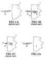
- FIGS. 1A-1Care views depicting previously known methods of injecting drugs and other bioactive agents into a tissue mass
- FIGS. 2A-2Care views depicting a method of injecting drugs and other bioactive agents into a tissue mass in accordance with the principles of the present invention
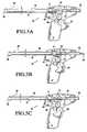
- FIGS. 3A and 3Bare views depicting apparatus of the present invention for injecting drugs and other bioactive agents into a tissue mass at multiple sites simultaneously;
- FIGS. 4A and 4Bare, respectively, a side view, partly in section, and isolation view of the internal components of apparatus of the present invention.
- FIGS. 5A-5Cdepict operation of the apparatus of FIG. 4 ;
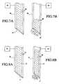
- FIGS. 6A and 6Bare cross-sectional views of apparatus and methods of the present invention for injecting a bioactive agent into an injured spinal cord;
- FIGS. 7A and 7Bare cross-sectional views of another embodiment of the apparatus of the present invention.
- FIGS. 8A and 8Bare cross-sectional views of a further alternative embodiment of apparatus of the present invention.
- FIG. 1Aillustrates a previously known injection needle 10 being brought into approximation with tissue mass T. Once the tip of needle 10 is inserted into the tissue, as shown in FIG. 1B , bioactive agent B, which may comprise stem cells, is injected into the tissue mass.
- bioactive agent Bwhich may comprise stem cells
- pressurized injection of a bioactive agentmay have a substantial detrimental effect both on the agent delivered and the tissue to be treated.
- pressurized injectioncauses the injectate stream to impinge violently against the tissue as it leaves the tip of the injection needle.
- the injectate streamis turbulent, and may experience rapid localized pressure fluctuations. These effects may damage the bioactive agent, particularly where the agent comprises stem cells, by rupturing the cell membrane or injuring the cellular components.
- FIGS. 2A to 2Capparatus and methods of the present invention are described that overcome the drawbacks of previously known systems for delivering fragile bioactive agents, such as stem cells.
- needle 20is first approximated to spinal cord tissue mass T.
- FIG. 2Bneedle 20 is shown inserted into the tissue mass.
- FIG. 2Cas needle 20 is withdrawn from the tissue mass, bioactive agent B is delivered from the tip of the needle and deposited in the needle track.
- the bioactive agentis injected into the tissue under little pressure and with substantially less turbulence and localized pressure fluctuation than in previously known injection systems. Also, the bioactive agent will not damage the tissue mass by splitting the tissue along naturally-occurring striations. These benefits of atraumatic injection may be particularly advantageous in the repair of an injured or severed spinal cord.
- distal end 25includes selectively extendable needles 26 .
- needles 26are configured to flare outward when extended beyond distal end 25 of the apparatus, thereby enhancing dispersal of the bioactive agent into tissue mass T.
- needles 26are configured to delivery bioactive agent B into the tissue mass while minimizing barotrauma to the bioactive agent and the injury to the tissue mass.
- distal end 25illustratively includes three needles 26 , a greater or lesser number of needles may be employed without departing from the spirit of the present invention.
- Apparatus 30comprises handle 31 that is configured to accept conventional syringe 28 , which may be loaded with a preselected bioactive agent, such as stem cells in a nutrient solution.
- the barrel of syringe 28is removably coupled to tube 32 via fluid-tight seal 33 .
- Tube 32which carries one or more tissue-piercing needles at its distal end, is arranged to reciprocate through sleeve 34 so that the distal tip of the needle extends beyond bushing 35 when the device is actuated.
- Piston 29 of syringe 28is removably coupled to block 36 and rails 37 .
- Handle 31includes trigger 38 that may be depressed to selectively actuate apparatus 30 .
- trigger 38is coupled to tube 32 via gear train 39 and linkage 40 .
- Clamp 41is configured to grip and reciprocate the body of the syringe in accordance with the degree of actuation of trigger 38 .
- Each of rails 37preferably includes a portion that forms a rack to permit forward movement of piston 29 of the syringe during a first range of motion of trigger 38 , and then retain piston 29 stationary relative to rails 37 during a second range of motion of the trigger.
- Link 40is coupled to clamp 41 so that, after syringe 28 and piston 29 are advanced during the initial range of motion of the trigger, the piston is held stationary while clamp 41 retracts tube 32 and needles from the needle track(s) and simultaneously urges the body of syringe 28 proximally. This motion causes the bioactive material within syringe 28 to be dispensed into the needle track(s) (see FIGS. 2 and 3 ) at low velocity and with little or no barotrauma. As depicted in FIG. 4B (but omitted elsewhere for clarity), trigger 38 and link 40 preferably are biased by springs 42 and 43 , respectively, to return the mechanism to its starting position when trigger 38 is released.
- FIGS. 5A-5Coperation of apparatus 30 is described.
- trigger 38 of the apparatusis shown at its initial position, and with syringe 28 and piston 29 in the proximal-most positions.
- gear train 39 and link 40urge syringe 28 , piston 29 and rails 37 in the distal direction in unison.
- tube 32 and clamp 41to be advanced distally, in turn causing needles 43 to extend beyond bushing 35 .
- the tissue-piercing end of tube 33includes three needles 43 that flare outward upon entering into a tissue mass, as depicted in FIG. 3A .
- proximal translation of clamp 41also causes the distance between block 36 and the proximal-most portion of syringe 28 to shorten. This action applies sufficient pressure to the contents of syringe 28 to dispense the bioactive agent into the needle tracks formed by needles 43 as the needles withdraw from the tissue.
- springs 42 and 43return tube 32 and clamp 41 to the starting position, shown in FIG. 5A . Apparatus 30 then may be repositioned, and the above process repeated.
- the volume of injected material delivered into the target tissuemay be adjusted depending upon the target tissue milieu. For example, for tissue or muscle that is fairly elastic, such as heart muscle, additional material may be injected to create low-pressure compartments within the tissue. On the other hand, lower volumes may be employed in less resilient structures, such as the spinal cord and brain.
- needles 43 ′ of apparatus 30may have different predetermined lengths so as to deliver the bioactive agent at various depths within spinal cord S to treat injured region D.
- needles 43 ′may first be used to deliver bioactive agent on a first side of a severed region D of spinal cord S, and then moved and applied to the opposite side of the severed region (shown in dotted line in FIG. 6A ).
- needles 43 ′may be arranged to be individually rotated so that the bioactive agent is dispersed in preselected directions.
- FIG. 6Bdepicts the use of grid 50 to guide needles 43 ′ into predetermined locations along spinal cord S.
- Grid 50comprises block 51 having a plurality of through holes 52 disposed along its surface to provide a predetermined separation between injection regions.
- grid 50lends structural support to damaged spinal region D during stem cell injection.
- apparatus 30may be used to inject needles 43 ′ at a first location, and then repositioned using grid 50 (as shown in dotted line) to provide subsequent injections.
- a predetermined amount of cerebrospinal fluidmay be removed from spinal cord S prior to injecting the bioactive agent.
- the amount of cerebrospinal fluid removedis substantially equivalent to the amount of bioactive agent, e.g., stem cell solution, injected into the spinal cord.
- This step of the methodis expected to enhance atraumatic delivery of the bioactive agent by reducing the risk that the injection prevents injury to the spinal artery or surrounding delicate tissue during injection.
- Needle 60comprises a glass or polymer microfiber adapted to receive and transmit electric signals, and includes tissue-piercing distal end 61 and interior lumen 62 . Needle 60 is loaded with a bioactive agent, preferably comprising stem cells 65 , and in addition is coupled to power supply 63 that applies an electric field longitudinally along needle 60 .
- a bioactive agentpreferably comprising stem cells 65
- Stem cells 95are believed to be negatively charged in the natural state, so that they are drawn toward the positive charge at distal end 61 of needle 60 .
- an ionic solution containing negatively charged particlesmay be added to the bioactive agent prior to injection to increase the attraction of the stem cells towards a positive charge.
- the movement of stem cells 65 toward the positive chargecauses a predetermined amount of the stem cells to be ejected from distal end 61 into a target tissue mass, such as a damaged region of spinal cord.
- Needle 60optionally may transmit a signal that defines a location of the needle when viewed using an MRI or CT device.
- Needle 70comprises an electroactive polymer that forms an actuator, and includes tissue-piercing distal end 71 and interior lumen 72 . Needle 70 is loaded with a bioactive agent, preferably comprising stem cells 75 , and is coupled to power supply 73 that applies an electric field longitudinally along needle 70 .
- Electroactive polymersare members of the family of plastics referred to as “conducting polymers,” and are preferred for the practice of the present invention due to their small size, large force and strain and low cost.
- injection needle 70comprises an electroactive polymer that is adapted to contract in response to electrical stimulation.
- Suitable electroactive polymersinclude, but are not limited to, polypyrrole, polyacetylene, polyaniline and polysulfone. Oxidation or reduction of these polymers leads to a charge imbalance that results in a flow of ions (dopants) into the material in order to balance charge.
- the ionsenter the polymer from an tonically conductive electrolyte medium that is coupled to the polymer surface. Conversely, if ions are already present in the polymer when it is oxidized or reduced, they may exit the polymer.
- Electroactive polymersDimensional changes in electroactive polymers may be triggered by the mass transfer of ions into or out of the polymer.
- the expansionis due to ion insertion between chains, whereas repulsion between chains is the dominant effect for other electroactive polymers.
- the mass transfer of ions into and out of the electroactive polymerleads to an expansion or contraction of the polymer.
- needle 70may be contracted such that a predetermined amount of bioactive agent is ejected from distal end 71 of the needle.
- needle 70comprises an electroactive polymer that is configured to contract when an electric charge is applied to the needle by power supply 73 .
- Needle 70has a first diameter ( FIG. 8A ) and a second, contracted diameter ( FIG. 8B ) when energized.
- FIG. 8Bwhen an electrostatic charge is applied to injection needle 70 , the needle contracts and the diameter of lumen 72 decreases, thereby expelling a predetermined amount of stem cells 75 out of distal end 71 of needle 70 .
- constriction of lumen 72is a bulk phenomenon that imposes a low-level distributed compressive force to the bioactive agent disposed in the lumen. Accordingly, substantially smaller local pressure fluctations will be imposed on the bioactive agent as compared to pressurized injection using a syringe, thereby reducing barotrauma and leading to substantially better viability of the implanted stem cells.
- the embodiments of FIGS. 7 and 8may include multiple needle tips to deliver bioactive agent at several sites or depths simultaneously, and may be used with a grid, such as described with respect to FIG. 6 , to deliver the bioactive agent according to a predetermined pattern.
- power supplies 63 and 73 of the embodiments of FIGS. 7 and 8may include controllers that control operation of the electric fields applied to the needles so that predetermined amounts of bioactive agent are delivered by the needles when activated.
Landscapes
- Health & Medical Sciences (AREA)
- Surgery (AREA)
- Life Sciences & Earth Sciences (AREA)
- Medical Informatics (AREA)
- Animal Behavior & Ethology (AREA)
- Engineering & Computer Science (AREA)
- Biomedical Technology (AREA)
- Heart & Thoracic Surgery (AREA)
- Pathology (AREA)
- Molecular Biology (AREA)
- Nuclear Medicine, Radiotherapy & Molecular Imaging (AREA)
- General Health & Medical Sciences (AREA)
- Public Health (AREA)
- Veterinary Medicine (AREA)
- Infusion, Injection, And Reservoir Apparatuses (AREA)
- Media Introduction/Drainage Providing Device (AREA)
- Materials For Medical Uses (AREA)
- Feeding, Discharge, Calcimining, Fusing, And Gas-Generation Devices (AREA)
- Pharmaceuticals Containing Other Organic And Inorganic Compounds (AREA)
Abstract
Description
Claims (8)
Priority Applications (2)
| Application Number | Priority Date | Filing Date | Title |
|---|---|---|---|
| US12/041,561US7862551B2 (en) | 2004-07-19 | 2008-03-03 | Apparatus and methods for treating tissue using passive injection systems |
| US12/978,293US20110152833A1 (en) | 2004-07-19 | 2010-12-23 | Apparatus and methods for treating tissue using passive injection systems |
Applications Claiming Priority (3)
| Application Number | Priority Date | Filing Date | Title |
|---|---|---|---|
| US10/894,810US7632262B2 (en) | 2004-07-19 | 2004-07-19 | Systems and methods for atraumatic implantation of bio-active agents |
| US10/977,594US7338471B2 (en) | 2004-07-19 | 2004-10-29 | Apparatus and methods for treating tissue using passive injection systems |
| US12/041,561US7862551B2 (en) | 2004-07-19 | 2008-03-03 | Apparatus and methods for treating tissue using passive injection systems |
Related Parent Applications (1)
| Application Number | Title | Priority Date | Filing Date |
|---|---|---|---|
| US10/977,594ContinuationUS7338471B2 (en) | 2004-07-19 | 2004-10-29 | Apparatus and methods for treating tissue using passive injection systems |
Related Child Applications (1)
| Application Number | Title | Priority Date | Filing Date |
|---|---|---|---|
| US12/978,293ContinuationUS20110152833A1 (en) | 2004-07-19 | 2010-12-23 | Apparatus and methods for treating tissue using passive injection systems |
Publications (2)
| Publication Number | Publication Date |
|---|---|
| US20080154201A1 US20080154201A1 (en) | 2008-06-26 |
| US7862551B2true US7862551B2 (en) | 2011-01-04 |
Family
ID=35600417
Family Applications (5)
| Application Number | Title | Priority Date | Filing Date |
|---|---|---|---|
| US10/894,810Expired - LifetimeUS7632262B2 (en) | 2004-07-19 | 2004-07-19 | Systems and methods for atraumatic implantation of bio-active agents |
| US10/977,594Expired - LifetimeUS7338471B2 (en) | 2004-07-19 | 2004-10-29 | Apparatus and methods for treating tissue using passive injection systems |
| US12/041,561Expired - LifetimeUS7862551B2 (en) | 2004-07-19 | 2008-03-03 | Apparatus and methods for treating tissue using passive injection systems |
| US12/637,701Expired - Fee RelatedUS8377032B2 (en) | 2004-07-19 | 2009-12-14 | Systems and methods for atraumatic implantation of bio-active agents |
| US12/978,293AbandonedUS20110152833A1 (en) | 2004-07-19 | 2010-12-23 | Apparatus and methods for treating tissue using passive injection systems |
Family Applications Before (2)
| Application Number | Title | Priority Date | Filing Date |
|---|---|---|---|
| US10/894,810Expired - LifetimeUS7632262B2 (en) | 2004-07-19 | 2004-07-19 | Systems and methods for atraumatic implantation of bio-active agents |
| US10/977,594Expired - LifetimeUS7338471B2 (en) | 2004-07-19 | 2004-10-29 | Apparatus and methods for treating tissue using passive injection systems |
Family Applications After (2)
| Application Number | Title | Priority Date | Filing Date |
|---|---|---|---|
| US12/637,701Expired - Fee RelatedUS8377032B2 (en) | 2004-07-19 | 2009-12-14 | Systems and methods for atraumatic implantation of bio-active agents |
| US12/978,293AbandonedUS20110152833A1 (en) | 2004-07-19 | 2010-12-23 | Apparatus and methods for treating tissue using passive injection systems |
Country Status (7)
| Country | Link |
|---|---|
| US (5) | US7632262B2 (en) |
| EP (4) | EP2340868B1 (en) |
| JP (2) | JP4774403B2 (en) |
| AT (1) | ATE526054T1 (en) |
| AU (2) | AU2005274774B2 (en) |
| CA (2) | CA2573844C (en) |
| WO (2) | WO2006020255A2 (en) |
Cited By (5)
| Publication number | Priority date | Publication date | Assignee | Title |
|---|---|---|---|---|
| WO2014151931A1 (en) | 2013-03-15 | 2014-09-25 | The Regents Of The University Of California | Systems for selectively migrating cells using electric fields |
| US9956384B2 (en) | 2014-01-24 | 2018-05-01 | Cook Medical Technologies Llc | Articulating balloon catheter and method for using the same |
| US10328213B2 (en) | 2013-03-15 | 2019-06-25 | Muffin Incorporated | Cell injection needle |
| US10398844B2 (en) | 2012-11-02 | 2019-09-03 | Cook Medical Technologies Llc | Controlled injection devices, systems, and methods |
| WO2023187724A1 (en) | 2022-04-01 | 2023-10-05 | Ecole Polytechnique Federale De Lausanne (Epfl) | Tumescense monitoring system for diagnosing erectile dysfunction and methods of use |
Families Citing this family (48)
| Publication number | Priority date | Publication date | Assignee | Title |
|---|---|---|---|---|
| US7632262B2 (en)* | 2004-07-19 | 2009-12-15 | Nexeon Medical Systems, Inc. | Systems and methods for atraumatic implantation of bio-active agents |
| US20090118673A1 (en)* | 2007-11-07 | 2009-05-07 | Jerett Creed | Needle injection catheter |
| US8075519B2 (en)* | 2007-12-06 | 2011-12-13 | Abbott Cardiovascular Systems Inc. | Agent delivery catheter having a radially expandable centering support members |
| US8133208B2 (en)* | 2008-04-02 | 2012-03-13 | Bsecs Holdings, Llc | Injection control method and device |
| US20090254060A1 (en)* | 2008-04-02 | 2009-10-08 | Hetherington Hugh E | Motor assembly for injection control device |
| US20090312617A1 (en)* | 2008-06-12 | 2009-12-17 | Jerett Creed | Needle injection catheter |
| US7824359B2 (en)* | 2008-07-24 | 2010-11-02 | Solomon Clifford T | Bioinjection device |
| US7989526B2 (en)* | 2008-10-30 | 2011-08-02 | E. I. Du Pont De Nemours And Company | Flame resistant semiaromatic polyamide resin compositions and processes for the preparation of semiaromatic polyamide resin compositions exhibiting increased melt flow and articles therefrom |
| US8900193B2 (en)* | 2008-12-31 | 2014-12-02 | St. Jude Medical, Atrial Fibrillation Division, Inc. | Fast-acting or rotating transseptal needle |
| FR2950534B1 (en)* | 2009-09-29 | 2011-09-30 | M2Ct | COMPENSATION DEVICE FOR THE REMOVAL OF A CHEMOTHERAPY NEEDLE |
| FR2950535B1 (en)* | 2009-09-30 | 2011-09-30 | M2Ct | DEVICE COMPLEMENTARY TO A NEEDLE OF CHEMOTHERAPY |
| EP2308531A3 (en) | 2009-09-29 | 2012-12-12 | M2CT (Sarl) | Compensation device when retracting a chemotherapy needle |
| US8864711B2 (en)* | 2010-01-27 | 2014-10-21 | Warsaw Orthopedic, Inc. | Drug dispensing balloon for treating disc disease or pain |
| EP2389969A1 (en) | 2010-05-26 | 2011-11-30 | Omrix Biopharmaceuticals Ltd. | A device for injecting a substance |
| US8554309B2 (en)* | 2010-09-23 | 2013-10-08 | Hologic, Inc. | Localizing obturator with site marking capability |
| US9237925B2 (en) | 2011-04-22 | 2016-01-19 | Ablative Solutions, Inc. | Expandable catheter system for peri-ostial injection and muscle and nerve fiber ablation |
| US8663190B2 (en) | 2011-04-22 | 2014-03-04 | Ablative Solutions, Inc. | Expandable catheter system for peri-ostial injection and muscle and nerve fiber ablation |
| US9056185B2 (en) | 2011-08-24 | 2015-06-16 | Ablative Solutions, Inc. | Expandable catheter system for fluid injection into and deep to the wall of a blood vessel |
| US20130053792A1 (en) | 2011-08-24 | 2013-02-28 | Ablative Solutions, Inc. | Expandable catheter system for vessel wall injection and muscle and nerve fiber ablation |
| DE102011089735A1 (en)* | 2011-12-23 | 2013-06-27 | Robert Bosch Gmbh | machine tool |
| ES2562838T3 (en)* | 2012-01-31 | 2016-03-08 | Trichoscience Innovations Inc. | Injection devices |
| US9393364B2 (en) | 2012-07-17 | 2016-07-19 | Cook Medical Technologies Llc | Multi-lumen biologic-delivering device |
| AU2013299537A1 (en)* | 2012-08-08 | 2015-02-19 | Presage Biosciences, Inc. | Extrusion methods and devices for drug delivery |
| US20140073907A1 (en) | 2012-09-12 | 2014-03-13 | Convergent Life Sciences, Inc. | System and method for image guided medical procedures |
| US9526827B2 (en) | 2012-10-29 | 2016-12-27 | Ablative Solutions, Inc. | Peri-vascular tissue ablation catheter with support structures |
| US10736656B2 (en) | 2012-10-29 | 2020-08-11 | Ablative Solutions | Method for painless renal denervation using a peri-vascular tissue ablation catheter with support structures |
| US10881458B2 (en) | 2012-10-29 | 2021-01-05 | Ablative Solutions, Inc. | Peri-vascular tissue ablation catheters |
| US10945787B2 (en) | 2012-10-29 | 2021-03-16 | Ablative Solutions, Inc. | Peri-vascular tissue ablation catheters |
| US10226278B2 (en) | 2012-10-29 | 2019-03-12 | Ablative Solutions, Inc. | Method for painless renal denervation using a peri-vascular tissue ablation catheter with support structures |
| US9301795B2 (en) | 2012-10-29 | 2016-04-05 | Ablative Solutions, Inc. | Transvascular catheter for extravascular delivery |
| US9949652B2 (en) | 2013-10-25 | 2018-04-24 | Ablative Solutions, Inc. | Apparatus for effective ablation and nerve sensing associated with denervation |
| US9931046B2 (en) | 2013-10-25 | 2018-04-03 | Ablative Solutions, Inc. | Intravascular catheter with peri-vascular nerve activity sensors |
| US10517666B2 (en) | 2013-10-25 | 2019-12-31 | Ablative Solutions, Inc. | Apparatus for effective ablation and nerve sensing associated with denervation |
| TWI689326B (en) | 2014-08-06 | 2020-04-01 | 加拿大商複製細胞生命科學公司 | Injection devices |
| US10039592B2 (en)* | 2014-09-17 | 2018-08-07 | Covidien Lp | Deployment mechanisms for surgical instruments |
| US20160338729A1 (en)* | 2015-05-19 | 2016-11-24 | Jim Hassett | Catheter system for left heart access |
| EP3552652B2 (en) | 2015-08-18 | 2024-07-03 | B. Braun Melsungen AG | Catheter devices with valves |
| US10610669B2 (en)* | 2016-03-16 | 2020-04-07 | Krishna Rocha-Singh, M.D. | Apparatus and method for promoting angiogenesis in ischemic tissue |
| US10631532B1 (en)* | 2016-11-04 | 2020-04-28 | Charles Joseph Kowalski | Invasive plant species infusion applicator |
| CN109966592A (en)* | 2017-02-04 | 2019-07-05 | 王才丰 | A kind of large dosage of needleless injector that can independently take medicine |
| WO2018167002A1 (en)* | 2017-03-16 | 2018-09-20 | Koninklijke Philips N.V. | Tilt-controlled grid |
| EP3415106B1 (en) | 2017-06-14 | 2022-08-03 | IMEC vzw | Brain interaction apparatus, cranial anchor, and related systems |
| US11938286B2 (en)* | 2018-02-26 | 2024-03-26 | Cti Vascular Ag | Usable-length-selectable catheter to treat vascular pathologies |
| CN108836448A (en)* | 2018-06-26 | 2018-11-20 | 陈克银 | A kind of needle knife mirror enhancing perfusion device |
| US10849685B2 (en) | 2018-07-18 | 2020-12-01 | Ablative Solutions, Inc. | Peri-vascular tissue access catheter with locking handle |
| WO2020127328A1 (en) | 2018-12-17 | 2020-06-25 | B. Braun Melsungen Ag | Over-the-needle catheter assemblies and related manufacturing method |
| CN109498972A (en)* | 2018-12-20 | 2019-03-22 | 刘佰万 | A kind of clinical Respiratory Medicine of novel improved structure pressurization chemical sprayer |
| CN115581495A (en)* | 2022-10-21 | 2023-01-10 | 重庆医科大学附属第二医院 | Varicosity treatment device |
Citations (33)
| Publication number | Priority date | Publication date | Assignee | Title |
|---|---|---|---|---|
| US3880163A (en) | 1973-10-26 | 1975-04-29 | Jack H Ritterskamp | Medicinal syringe actuating device |
| US4067334A (en) | 1976-10-29 | 1978-01-10 | Haller J Gilbert | Self-injecting hypodermic syringe device |
| US4108177A (en)* | 1976-04-23 | 1978-08-22 | Michel Louis Paul Pistor | Automatic injector device |
| US4676781A (en)* | 1982-12-31 | 1987-06-30 | N.J. Phillips Pty. Limited | Injector |
| US4710162A (en)* | 1986-10-31 | 1987-12-01 | Johnson Gerald W | Fat collection and injection process into same body |
| US4950233A (en)* | 1988-10-05 | 1990-08-21 | Abramowitz Joseph M | Nerve block needle and safety method of use |
| US5244460A (en) | 1991-11-27 | 1993-09-14 | The United States Of America As Represented By The Department Of Health And Human Services | Method to foster myocardial blood vessel growth and improve blood flow to the heart |
| US5273532A (en)* | 1991-09-03 | 1993-12-28 | Texas Instruments Incorporated | Injector for hypodermically implanting an object in a living being |
| US5419777A (en) | 1994-03-10 | 1995-05-30 | Bavaria Medizin Technologie Gmbh | Catheter for injecting a fluid or medicine |
| WO1995026776A1 (en) | 1994-04-05 | 1995-10-12 | Faxon David P | Catheter for delivering therapeutic agents |
| US5531780A (en)* | 1992-09-03 | 1996-07-02 | Pacesetter, Inc. | Implantable stimulation lead having an advanceable therapeutic drug delivery system |
| US5655548A (en) | 1996-09-16 | 1997-08-12 | Circulation, Inc. | Method for treatment of ischemic heart disease by providing transvenous myocardial perfusion |
| US5730741A (en) | 1997-02-07 | 1998-03-24 | Eclipse Surgical Technologies, Inc. | Guided spiral catheter |
| US5860739A (en)* | 1997-03-05 | 1999-01-19 | Cannon; Mark L. | Automatic mixing syringe for dental materials |
| US5910150A (en) | 1996-12-02 | 1999-06-08 | Angiotrax, Inc. | Apparatus for performing surgery |
| DE29903726U1 (en) | 1998-03-03 | 1999-07-01 | Hwang, Tsong-Ming, Lin-Kou Hsiang, Taipeh | Safety syringe with a needle tube |
| US6024120A (en) | 1998-09-25 | 2000-02-15 | Sherwood Services Ag | Pressure relief valve with moving diaphragm |
| US6051008A (en) | 1996-12-02 | 2000-04-18 | Angiotrax, Inc. | Apparatus having stabilization members for percutaneously performing surgery and methods of use |
| US6102887A (en) | 1998-08-11 | 2000-08-15 | Biocardia, Inc. | Catheter drug delivery system and method for use |
| US6120520A (en) | 1997-05-27 | 2000-09-19 | Angiotrax, Inc. | Apparatus and methods for stimulating revascularization and/or tissue growth |
| US6159196A (en) | 1998-03-09 | 2000-12-12 | Ruiz; Carlos | Methods and apparatus for transvascular muscular revascularization and drug delivery |
| US6264637B1 (en) | 1997-06-26 | 2001-07-24 | Thomas Hogan | Marking syringe |
| US6302870B1 (en) | 1999-04-29 | 2001-10-16 | Precision Vascular Systems, Inc. | Apparatus for injecting fluids into the walls of blood vessels, body cavities, and the like |
| US20020049414A1 (en) | 2000-10-03 | 2002-04-25 | Nobles Anthony A. | Fluid delivery and extraction device and method |
| US6432119B1 (en) | 1999-03-17 | 2002-08-13 | Angiotrax, Inc. | Apparatus and methods for performing percutaneous myocardial revascularization and stimulating angiogenesis using autologous materials |
| US6544236B1 (en)* | 1999-02-10 | 2003-04-08 | Sub-Q, Incorporated | Device, system and method for improving delivery of hemostatic material |
| US20030191449A1 (en) | 1999-08-05 | 2003-10-09 | Kensey Nash Corporation | Systems for delivering agents into targeted tissue of a living being |
| US20040092892A1 (en)* | 2002-11-01 | 2004-05-13 | Jonathan Kagan | Apparatus and methods for treatment of morbid obesity |
| US20050124999A1 (en)* | 2003-10-31 | 2005-06-09 | Teitelbaum George P. | Device and method for radial delivery of a structural element |
| US20050256361A1 (en)* | 2002-07-03 | 2005-11-17 | Christian Mathieu | Implant inserting device |
| US20050261633A1 (en) | 2004-05-19 | 2005-11-24 | Khalaj Ben M | Rechargeable handheld injection device with reversible drive having adjustable syringe cradle |
| US7316692B2 (en) | 2003-08-12 | 2008-01-08 | Boston Scientific Scimed, Inc. | Laser-cut clot puller |
| US7338471B2 (en) | 2004-07-19 | 2008-03-04 | Paragon Intellectual Properties, Llc | Apparatus and methods for treating tissue using passive injection systems |
Family Cites Families (26)
| Publication number | Priority date | Publication date | Assignee | Title |
|---|---|---|---|---|
| US3081770A (en)* | 1960-09-21 | 1963-03-19 | John M Hunter | Surgical instrument |
| US3467096A (en)* | 1966-04-12 | 1969-09-16 | Ferrell S Horn | Multiple hypodermic syringe arrangement |
| US3941127A (en)* | 1974-10-03 | 1976-03-02 | Froning Edward C | Apparatus and method for stereotaxic lateral extradural disc puncture |
| CA1051330A (en)* | 1974-10-09 | 1979-03-27 | John T. Alden | Pneumatic tire |
| GB8522037D0 (en)* | 1985-09-05 | 1985-10-09 | Trimark R & D Ltd | Closure device |
| US4687473A (en)* | 1986-02-06 | 1987-08-18 | Burron Medical Inc. | Self-contained secondary solution set |
| US5284479A (en)* | 1989-08-30 | 1994-02-08 | N.V. Nederlandsche Apparatenfabriek Nedap | Implanter |
| US5562613A (en)* | 1991-07-02 | 1996-10-08 | Intermed, Inc. | Subcutaneous drug delivery device |
| US5738650A (en)* | 1993-01-29 | 1998-04-14 | Becton, Dickinson And Company | Subarachnoid needle and method for administering therapeutic agents to the subarachnoid space |
| US5457041A (en)* | 1994-03-25 | 1995-10-10 | Science Applications International Corporation | Needle array and method of introducing biological substances into living cells using the needle array |
| US5540658A (en)* | 1994-06-27 | 1996-07-30 | Innerdyne, Inc. | Transcervical uterine access and sealing device |
| WO1996009849A1 (en)* | 1994-09-27 | 1996-04-04 | Societe De Conseils De Recherches Et D'applications Scientifiques, S.A. | Safety injection device |
| US5860741A (en)* | 1996-03-25 | 1999-01-19 | Oriental System Technology, Inc. | Absolute radiation thermometer |
| US5830210A (en) | 1996-10-21 | 1998-11-03 | Plc Medical Systems, Inc. | Catheter navigation apparatus |
| US6102926A (en)* | 1996-12-02 | 2000-08-15 | Angiotrax, Inc. | Apparatus for percutaneously performing myocardial revascularization having means for sensing tissue parameters and methods of use |
| US5830188A (en)* | 1996-12-11 | 1998-11-03 | Board Of Regents, The University Of Texas System | Curved cannula for continuous spinal anesthesia |
| US5941983A (en)* | 1997-06-24 | 1999-08-24 | Hewlett-Packard Company | Out-of-order execution using encoded dependencies between instructions in queues to determine stall values that control issurance of instructions from the queues |
| JPH1142284A (en)* | 1997-07-25 | 1999-02-16 | Ube Ind Ltd | Vascular prosthesis with stent |
| US6682500B2 (en)* | 1998-01-29 | 2004-01-27 | David Soltanpour | Synthetic muscle based diaphragm pump apparatuses |
| US6450937B1 (en)* | 1999-12-17 | 2002-09-17 | C. R. Bard, Inc. | Needle for implanting brachytherapy seeds |
| US6599274B1 (en)* | 2000-01-20 | 2003-07-29 | John Kucharczyk | Cell delivery catheter and method |
| EP1301228B1 (en)* | 2000-07-13 | 2008-07-23 | Abbott Cardiovascular Systems Inc. | Deployment system for myocardial cellular material |
| WO2002043312A2 (en)* | 2000-11-21 | 2002-05-30 | Koninklijke Philips Electronics N.V. | A communication system having bad frame indicator means for resynchronization purposes |
| EP1452586B1 (en)* | 2001-10-30 | 2012-05-30 | Nc Medical Research Inc. | Method of inducing differentiation of mesodermal stem cells into nervous system cells |
| US20030229321A1 (en)* | 2002-06-05 | 2003-12-11 | Timothy Simon | Needle with slotted tip |
| JP2004026761A (en)* | 2002-06-27 | 2004-01-29 | Olympus Corp | Capsule for injecting into affected part and liquid for injecting into affected part |
- 2004
- 2004-07-19USUS10/894,810patent/US7632262B2/ennot_activeExpired - Lifetime
- 2004-10-29USUS10/977,594patent/US7338471B2/ennot_activeExpired - Lifetime
- 2005
- 2005-07-18JPJP2007522631Apatent/JP4774403B2/ennot_activeExpired - Lifetime
- 2005-07-18WOPCT/US2005/025469patent/WO2006020255A2/enactiveApplication Filing
- 2005-07-18EPEP11150671.3Apatent/EP2340868B1/ennot_activeExpired - Lifetime
- 2005-07-18CACA2573844Apatent/CA2573844C/ennot_activeExpired - Lifetime
- 2005-07-18EPEP20050773060patent/EP1773441B1/ennot_activeExpired - Lifetime
- 2005-07-18EPEP11150581Apatent/EP2343099A1/ennot_activeWithdrawn
- 2005-07-18WOPCT/US2005/025470patent/WO2006020256A2/enactiveApplication Filing
- 2005-07-18AUAU2005274774Apatent/AU2005274774B2/ennot_activeExpired
- 2005-07-18AUAU2005274775Apatent/AU2005274775B2/ennot_activeExpired
- 2005-07-18JPJP2007522630Apatent/JP4934029B2/ennot_activeExpired - Lifetime
- 2005-07-18EPEP05772267Apatent/EP1773440B1/ennot_activeExpired - Lifetime
- 2005-07-18CACA2574089Apatent/CA2574089C/ennot_activeExpired - Lifetime
- 2005-07-18ATAT05772267Tpatent/ATE526054T1/ennot_activeIP Right Cessation
- 2008
- 2008-03-03USUS12/041,561patent/US7862551B2/ennot_activeExpired - Lifetime
- 2009
- 2009-12-14USUS12/637,701patent/US8377032B2/ennot_activeExpired - Fee Related
- 2010
- 2010-12-23USUS12/978,293patent/US20110152833A1/ennot_activeAbandoned
Patent Citations (35)
| Publication number | Priority date | Publication date | Assignee | Title |
|---|---|---|---|---|
| US3880163A (en) | 1973-10-26 | 1975-04-29 | Jack H Ritterskamp | Medicinal syringe actuating device |
| US4108177A (en)* | 1976-04-23 | 1978-08-22 | Michel Louis Paul Pistor | Automatic injector device |
| US4067334A (en) | 1976-10-29 | 1978-01-10 | Haller J Gilbert | Self-injecting hypodermic syringe device |
| US4676781A (en)* | 1982-12-31 | 1987-06-30 | N.J. Phillips Pty. Limited | Injector |
| US4710162A (en)* | 1986-10-31 | 1987-12-01 | Johnson Gerald W | Fat collection and injection process into same body |
| US4950233A (en)* | 1988-10-05 | 1990-08-21 | Abramowitz Joseph M | Nerve block needle and safety method of use |
| US5273532A (en)* | 1991-09-03 | 1993-12-28 | Texas Instruments Incorporated | Injector for hypodermically implanting an object in a living being |
| US5244460A (en) | 1991-11-27 | 1993-09-14 | The United States Of America As Represented By The Department Of Health And Human Services | Method to foster myocardial blood vessel growth and improve blood flow to the heart |
| US5531780A (en)* | 1992-09-03 | 1996-07-02 | Pacesetter, Inc. | Implantable stimulation lead having an advanceable therapeutic drug delivery system |
| US5419777A (en) | 1994-03-10 | 1995-05-30 | Bavaria Medizin Technologie Gmbh | Catheter for injecting a fluid or medicine |
| WO1995026776A1 (en) | 1994-04-05 | 1995-10-12 | Faxon David P | Catheter for delivering therapeutic agents |
| US5655548A (en) | 1996-09-16 | 1997-08-12 | Circulation, Inc. | Method for treatment of ischemic heart disease by providing transvenous myocardial perfusion |
| US5941893A (en) | 1996-12-02 | 1999-08-24 | Angiotrax, Inc. | Apparatus for transluminally performing surgery |
| US6051008A (en) | 1996-12-02 | 2000-04-18 | Angiotrax, Inc. | Apparatus having stabilization members for percutaneously performing surgery and methods of use |
| US5910150A (en) | 1996-12-02 | 1999-06-08 | Angiotrax, Inc. | Apparatus for performing surgery |
| US5730741A (en) | 1997-02-07 | 1998-03-24 | Eclipse Surgical Technologies, Inc. | Guided spiral catheter |
| US5860739A (en)* | 1997-03-05 | 1999-01-19 | Cannon; Mark L. | Automatic mixing syringe for dental materials |
| US6120520A (en) | 1997-05-27 | 2000-09-19 | Angiotrax, Inc. | Apparatus and methods for stimulating revascularization and/or tissue growth |
| US6264637B1 (en) | 1997-06-26 | 2001-07-24 | Thomas Hogan | Marking syringe |
| DE29903726U1 (en) | 1998-03-03 | 1999-07-01 | Hwang, Tsong-Ming, Lin-Kou Hsiang, Taipeh | Safety syringe with a needle tube |
| US6159196A (en) | 1998-03-09 | 2000-12-12 | Ruiz; Carlos | Methods and apparatus for transvascular muscular revascularization and drug delivery |
| US6102887A (en) | 1998-08-11 | 2000-08-15 | Biocardia, Inc. | Catheter drug delivery system and method for use |
| US6346099B1 (en) | 1998-08-11 | 2002-02-12 | Biocardia, Inc. | Catheter drug delivery system and method for use |
| US6024120A (en) | 1998-09-25 | 2000-02-15 | Sherwood Services Ag | Pressure relief valve with moving diaphragm |
| US6544236B1 (en)* | 1999-02-10 | 2003-04-08 | Sub-Q, Incorporated | Device, system and method for improving delivery of hemostatic material |
| US6432119B1 (en) | 1999-03-17 | 2002-08-13 | Angiotrax, Inc. | Apparatus and methods for performing percutaneous myocardial revascularization and stimulating angiogenesis using autologous materials |
| US6302870B1 (en) | 1999-04-29 | 2001-10-16 | Precision Vascular Systems, Inc. | Apparatus for injecting fluids into the walls of blood vessels, body cavities, and the like |
| US20030191449A1 (en) | 1999-08-05 | 2003-10-09 | Kensey Nash Corporation | Systems for delivering agents into targeted tissue of a living being |
| US20020049414A1 (en) | 2000-10-03 | 2002-04-25 | Nobles Anthony A. | Fluid delivery and extraction device and method |
| US20050256361A1 (en)* | 2002-07-03 | 2005-11-17 | Christian Mathieu | Implant inserting device |
| US20040092892A1 (en)* | 2002-11-01 | 2004-05-13 | Jonathan Kagan | Apparatus and methods for treatment of morbid obesity |
| US7316692B2 (en) | 2003-08-12 | 2008-01-08 | Boston Scientific Scimed, Inc. | Laser-cut clot puller |
| US20050124999A1 (en)* | 2003-10-31 | 2005-06-09 | Teitelbaum George P. | Device and method for radial delivery of a structural element |
| US20050261633A1 (en) | 2004-05-19 | 2005-11-24 | Khalaj Ben M | Rechargeable handheld injection device with reversible drive having adjustable syringe cradle |
| US7338471B2 (en) | 2004-07-19 | 2008-03-04 | Paragon Intellectual Properties, Llc | Apparatus and methods for treating tissue using passive injection systems |
Non-Patent Citations (14)
| Title |
|---|
| Bonan, "Local Drug Delivery for the Treatment of Thrombus and Restenosis," J. Invasive Cardiol., 8 (8): 399-402 (Oct. 1996). |
| Mack et al., "Biologic bypass with the use of adenovirus-mediated gene transfer of the complementary deoxyribonucleic acid for vascular endothelial growth factor 121 improves myocardial perfusion and function in the ischemic porcine heart," J. Thoracic and Cardiovascular Surgery 115 (1): 168-177 (1997). |
| PCT International Search Report for PCT/US05/25469, 3 pages (mailed Oct. 3, 2006). |
| PCT International Search Report for PCT/US05/25470, 2 pages (mailed Sep. 21, 2006). |
| Sanborn et al., "Percutaneous Endocardial Gene Therapy: In Vivo Gene Transfer and Expression" (abstract), J. Am. Coll. Card. 33 (2 Suppl.): 262A (Feb. 1999). |
| Thompson et al., "Percutaneous Transvenous Cellular Cardiomyoplasty," J. Am. Coll. Card. 41 (11) 1964-1971 (Jun. 2003). |
| Uchida et al., "Angiogenic therapy of acute myocardial infarction by basic fibroblast growth factor and heparin sulfate," American Heart Journal 130 (6): 1182-1188 (Dec. 1995). |
| USPTO Final Office Action for U.S. Appl. No. 10/894,810. mailed Feb. 24, 2009 (8 pages). |
| USPTO Notice of Allowance and Notice of Allowability for U.S. Appl. No. 10/977,594, 7 pages (mailed Oct. 9, 2007). |
| USPTO Notice of Allowance for U.S. Appl. No. 10/894,810, mailed Aug. 6, 2009 (6 pages). |
| USPTO Office Action (final) for U.S. Appl. No. 10/894,810, 8 pages (mailed Aug. 28, 2007). |
| USPTO Office Action (non-final) for U.S. Appl. No. 10/894,810, 6 pages (mailed Jan. 17, 2007). |
| USPTO Office Action (non-final) for U.S. Appl. No. 10/894,810, 9 pages (mailed Jul. 25, 2008). |
| USPTO Office Action (non-final) for U.S. Appl. No. 10/977,594, 6 pages (mailed Dec. 15, 2006). |
Cited By (7)
| Publication number | Priority date | Publication date | Assignee | Title |
|---|---|---|---|---|
| US10398844B2 (en) | 2012-11-02 | 2019-09-03 | Cook Medical Technologies Llc | Controlled injection devices, systems, and methods |
| WO2014151931A1 (en) | 2013-03-15 | 2014-09-25 | The Regents Of The University Of California | Systems for selectively migrating cells using electric fields |
| US9044611B2 (en) | 2013-03-15 | 2015-06-02 | The Regents Of The University Of California | Systems and methods for selectively migrating cells using electric fields |
| US9662488B2 (en) | 2013-03-15 | 2017-05-30 | The Regents Of The University Of California | Systems and methods for selectively migrating cells using electric fields |
| US10328213B2 (en) | 2013-03-15 | 2019-06-25 | Muffin Incorporated | Cell injection needle |
| US9956384B2 (en) | 2014-01-24 | 2018-05-01 | Cook Medical Technologies Llc | Articulating balloon catheter and method for using the same |
| WO2023187724A1 (en) | 2022-04-01 | 2023-10-05 | Ecole Polytechnique Federale De Lausanne (Epfl) | Tumescense monitoring system for diagnosing erectile dysfunction and methods of use |
Also Published As
| Publication number | Publication date |
|---|---|
| JP2008506499A (en) | 2008-03-06 |
| EP1773441A4 (en) | 2010-07-28 |
| US20100331814A1 (en) | 2010-12-30 |
| EP2340868A1 (en) | 2011-07-06 |
| EP1773440A2 (en) | 2007-04-18 |
| AU2005274774A1 (en) | 2006-02-23 |
| JP2008506500A (en) | 2008-03-06 |
| EP1773440A4 (en) | 2010-08-04 |
| WO2006020256A2 (en) | 2006-02-23 |
| CA2574089C (en) | 2013-12-31 |
| US8377032B2 (en) | 2013-02-19 |
| EP2343099A1 (en) | 2011-07-13 |
| WO2006020256A3 (en) | 2006-12-28 |
| US20080154201A1 (en) | 2008-06-26 |
| EP1773441B1 (en) | 2015-05-20 |
| US7338471B2 (en) | 2008-03-04 |
| ATE526054T1 (en) | 2011-10-15 |
| AU2005274775B2 (en) | 2011-07-21 |
| AU2005274775A1 (en) | 2006-02-23 |
| JP4774403B2 (en) | 2011-09-14 |
| EP1773440B1 (en) | 2011-09-28 |
| EP2340868B1 (en) | 2017-03-29 |
| US20060015067A1 (en) | 2006-01-19 |
| US7632262B2 (en) | 2009-12-15 |
| AU2005274774B2 (en) | 2011-05-12 |
| US20060015085A1 (en) | 2006-01-19 |
| CA2573844C (en) | 2014-11-25 |
| CA2574089A1 (en) | 2006-03-23 |
| WO2006020256B1 (en) | 2007-01-25 |
| WO2006020255A2 (en) | 2006-02-23 |
| JP4934029B2 (en) | 2012-05-16 |
| CA2573844A1 (en) | 2006-02-23 |
| WO2006020255A3 (en) | 2006-11-30 |
| EP1773441A2 (en) | 2007-04-18 |
| US20110152833A1 (en) | 2011-06-23 |
Similar Documents
| Publication | Publication Date | Title |
|---|---|---|
| US7862551B2 (en) | Apparatus and methods for treating tissue using passive injection systems | |
| US10548659B2 (en) | High pressure pre-burst for improved fluid delivery | |
| JP5936203B2 (en) | Apparatus and process for applying a substance into mammalian tissue | |
| US7218962B2 (en) | Magnetically enhanced injection catheter | |
| US8992513B2 (en) | Endovascular plasma treatment device and method of use | |
| US20130060189A1 (en) | Multi-Needle Delivery System and Method | |
| CA2936906A1 (en) | Surgical methods/devices for tissue injury removal by tattooing of autologous stem cells | |
| US8603512B2 (en) | Methods for treating an injured nerve pathway | |
| EP2968752B1 (en) | Cell injection needle | |
| KR20220106071A (en) | Microneedle applicator | |
| US9433727B1 (en) | Tissue rejuvenation methods and tissue transfer devices suitable for implementation thereof |
Legal Events
| Date | Code | Title | Description |
|---|---|---|---|
| AS | Assignment | Owner name:NEXEON MEDSYSTEMS, INC., WEST VIRGINIA Free format text:MERGER;ASSIGNOR:PARAGON INTELLECTUAL PROPERTIES, LLC;REEL/FRAME:022137/0876 Effective date:20081031 Owner name:NEXEON MEDSYSTEMS, INC.,WEST VIRGINIA Free format text:MERGER;ASSIGNOR:PARAGON INTELLECTUAL PROPERTIES, LLC;REEL/FRAME:022137/0876 Effective date:20081031 | |
| STCF | Information on status: patent grant | Free format text:PATENTED CASE | |
| FEPP | Fee payment procedure | Free format text:PAYOR NUMBER ASSIGNED (ORIGINAL EVENT CODE: ASPN); ENTITY STATUS OF PATENT OWNER: LARGE ENTITY | |
| FPAY | Fee payment | Year of fee payment:4 | |
| AS | Assignment | Owner name:COOK MEDICAL TECHNOLOGIES LLC, INDIANA Free format text:ASSIGNMENT OF ASSIGNORS INTEREST;ASSIGNOR:NEXEON MEDSYSTEMS, INC.;REEL/FRAME:034174/0613 Effective date:20140923 | |
| MAFP | Maintenance fee payment | Free format text:PAYMENT OF MAINTENANCE FEE, 8TH YR, SMALL ENTITY (ORIGINAL EVENT CODE: M2552) Year of fee payment:8 | |
| FEPP | Fee payment procedure | Free format text:ENTITY STATUS SET TO UNDISCOUNTED (ORIGINAL EVENT CODE: BIG.); ENTITY STATUS OF PATENT OWNER: LARGE ENTITY | |
| MAFP | Maintenance fee payment | Free format text:PAYMENT OF MAINTENANCE FEE, 12TH YEAR, LARGE ENTITY (ORIGINAL EVENT CODE: M1553); ENTITY STATUS OF PATENT OWNER: LARGE ENTITY Year of fee payment:12 | |
| AS | Assignment | Owner name:WILMINGTON TRUST, NATIONAL ASSOCIATION, AS COLLATERAL AGENT, DELAWARE Free format text:SECURITY INTEREST;ASSIGNOR:COOK MEDICAL TECHNOLOGIES LLC;REEL/FRAME:066700/0277 Effective date:20240227 |