US7862540B2 - Ophthalmic injection device using shape memory alloy - Google Patents
Ophthalmic injection device using shape memory alloyDownload PDFInfo
- Publication number
- US7862540B2 US7862540B2US11/752,064US75206407AUS7862540B2US 7862540 B2US7862540 B2US 7862540B2US 75206407 AUS75206407 AUS 75206407AUS 7862540 B2US7862540 B2US 7862540B2
- Authority
- US
- United States
- Prior art keywords
- dispensing chamber
- chamber housing
- substance
- current
- housing
- Prior art date
- Legal status (The legal status is an assumption and is not a legal conclusion. Google has not performed a legal analysis and makes no representation as to the accuracy of the status listed.)
- Expired - Fee Related, expires
Links
Images


Classifications
- A—HUMAN NECESSITIES
- A61—MEDICAL OR VETERINARY SCIENCE; HYGIENE
- A61F—FILTERS IMPLANTABLE INTO BLOOD VESSELS; PROSTHESES; DEVICES PROVIDING PATENCY TO, OR PREVENTING COLLAPSING OF, TUBULAR STRUCTURES OF THE BODY, e.g. STENTS; ORTHOPAEDIC, NURSING OR CONTRACEPTIVE DEVICES; FOMENTATION; TREATMENT OR PROTECTION OF EYES OR EARS; BANDAGES, DRESSINGS OR ABSORBENT PADS; FIRST-AID KITS
- A61F9/00—Methods or devices for treatment of the eyes; Devices for putting in contact-lenses; Devices to correct squinting; Apparatus to guide the blind; Protective devices for the eyes, carried on the body or in the hand
- A61F9/0008—Introducing ophthalmic products into the ocular cavity or retaining products therein
- A61F9/0017—Introducing ophthalmic products into the ocular cavity or retaining products therein implantable in, or in contact with, the eye, e.g. ocular inserts
- A—HUMAN NECESSITIES
- A61—MEDICAL OR VETERINARY SCIENCE; HYGIENE
- A61M—DEVICES FOR INTRODUCING MEDIA INTO, OR ONTO, THE BODY; DEVICES FOR TRANSDUCING BODY MEDIA OR FOR TAKING MEDIA FROM THE BODY; DEVICES FOR PRODUCING OR ENDING SLEEP OR STUPOR
- A61M31/00—Devices for introducing or retaining media, e.g. remedies, in cavities of the body
- A—HUMAN NECESSITIES
- A61—MEDICAL OR VETERINARY SCIENCE; HYGIENE
- A61M—DEVICES FOR INTRODUCING MEDIA INTO, OR ONTO, THE BODY; DEVICES FOR TRANSDUCING BODY MEDIA OR FOR TAKING MEDIA FROM THE BODY; DEVICES FOR PRODUCING OR ENDING SLEEP OR STUPOR
- A61M5/00—Devices for bringing media into the body in a subcutaneous, intra-vascular or intramuscular way; Accessories therefor, e.g. filling or cleaning devices, arm-rests
- A61M5/14—Infusion devices, e.g. infusing by gravity; Blood infusion; Accessories therefor
- A61M5/142—Pressure infusion, e.g. using pumps
- A61M5/14212—Pumping with an aspiration and an expulsion action
- A61M5/14224—Diaphragm type
- A—HUMAN NECESSITIES
- A61—MEDICAL OR VETERINARY SCIENCE; HYGIENE
- A61M—DEVICES FOR INTRODUCING MEDIA INTO, OR ONTO, THE BODY; DEVICES FOR TRANSDUCING BODY MEDIA OR FOR TAKING MEDIA FROM THE BODY; DEVICES FOR PRODUCING OR ENDING SLEEP OR STUPOR
- A61M5/00—Devices for bringing media into the body in a subcutaneous, intra-vascular or intramuscular way; Accessories therefor, e.g. filling or cleaning devices, arm-rests
- A61M5/14—Infusion devices, e.g. infusing by gravity; Blood infusion; Accessories therefor
- A61M5/142—Pressure infusion, e.g. using pumps
- A61M5/145—Pressure infusion, e.g. using pumps using pressurised reservoirs, e.g. pressurised by means of pistons
- A61M5/1452—Pressure infusion, e.g. using pumps using pressurised reservoirs, e.g. pressurised by means of pistons pressurised by means of pistons
- A61M5/14546—Front-loading type injectors
- A—HUMAN NECESSITIES
- A61—MEDICAL OR VETERINARY SCIENCE; HYGIENE
- A61M—DEVICES FOR INTRODUCING MEDIA INTO, OR ONTO, THE BODY; DEVICES FOR TRANSDUCING BODY MEDIA OR FOR TAKING MEDIA FROM THE BODY; DEVICES FOR PRODUCING OR ENDING SLEEP OR STUPOR
- A61M5/00—Devices for bringing media into the body in a subcutaneous, intra-vascular or intramuscular way; Accessories therefor, e.g. filling or cleaning devices, arm-rests
- A61M5/44—Devices for bringing media into the body in a subcutaneous, intra-vascular or intramuscular way; Accessories therefor, e.g. filling or cleaning devices, arm-rests having means for cooling or heating the devices or media
- A61M5/445—Devices for bringing media into the body in a subcutaneous, intra-vascular or intramuscular way; Accessories therefor, e.g. filling or cleaning devices, arm-rests having means for cooling or heating the devices or media the media being heated in the reservoir, e.g. warming bloodbags
- A—HUMAN NECESSITIES
- A61—MEDICAL OR VETERINARY SCIENCE; HYGIENE
- A61F—FILTERS IMPLANTABLE INTO BLOOD VESSELS; PROSTHESES; DEVICES PROVIDING PATENCY TO, OR PREVENTING COLLAPSING OF, TUBULAR STRUCTURES OF THE BODY, e.g. STENTS; ORTHOPAEDIC, NURSING OR CONTRACEPTIVE DEVICES; FOMENTATION; TREATMENT OR PROTECTION OF EYES OR EARS; BANDAGES, DRESSINGS OR ABSORBENT PADS; FIRST-AID KITS
- A61F9/00—Methods or devices for treatment of the eyes; Devices for putting in contact-lenses; Devices to correct squinting; Apparatus to guide the blind; Protective devices for the eyes, carried on the body or in the hand
- A61F9/0008—Introducing ophthalmic products into the ocular cavity or retaining products therein
- A—HUMAN NECESSITIES
- A61—MEDICAL OR VETERINARY SCIENCE; HYGIENE
- A61M—DEVICES FOR INTRODUCING MEDIA INTO, OR ONTO, THE BODY; DEVICES FOR TRANSDUCING BODY MEDIA OR FOR TAKING MEDIA FROM THE BODY; DEVICES FOR PRODUCING OR ENDING SLEEP OR STUPOR
- A61M2205/00—General characteristics of the apparatus
- A61M2205/02—General characteristics of the apparatus characterised by a particular materials
- A61M2205/0244—Micromachined materials, e.g. made from silicon wafers, microelectromechanical systems [MEMS] or comprising nanotechnology
- A—HUMAN NECESSITIES
- A61—MEDICAL OR VETERINARY SCIENCE; HYGIENE
- A61M—DEVICES FOR INTRODUCING MEDIA INTO, OR ONTO, THE BODY; DEVICES FOR TRANSDUCING BODY MEDIA OR FOR TAKING MEDIA FROM THE BODY; DEVICES FOR PRODUCING OR ENDING SLEEP OR STUPOR
- A61M2205/00—General characteristics of the apparatus
- A61M2205/02—General characteristics of the apparatus characterised by a particular materials
- A61M2205/0266—Shape memory materials
- A—HUMAN NECESSITIES
- A61—MEDICAL OR VETERINARY SCIENCE; HYGIENE
- A61M—DEVICES FOR INTRODUCING MEDIA INTO, OR ONTO, THE BODY; DEVICES FOR TRANSDUCING BODY MEDIA OR FOR TAKING MEDIA FROM THE BODY; DEVICES FOR PRODUCING OR ENDING SLEEP OR STUPOR
- A61M2205/00—General characteristics of the apparatus
- A61M2205/02—General characteristics of the apparatus characterised by a particular materials
- A61M2205/0272—Electro-active or magneto-active materials
- A61M2205/0294—Piezoelectric materials
- A—HUMAN NECESSITIES
- A61—MEDICAL OR VETERINARY SCIENCE; HYGIENE
- A61M—DEVICES FOR INTRODUCING MEDIA INTO, OR ONTO, THE BODY; DEVICES FOR TRANSDUCING BODY MEDIA OR FOR TAKING MEDIA FROM THE BODY; DEVICES FOR PRODUCING OR ENDING SLEEP OR STUPOR
- A61M2205/00—General characteristics of the apparatus
- A61M2205/33—Controlling, regulating or measuring
- A61M2205/3331—Pressure; Flow
- A—HUMAN NECESSITIES
- A61—MEDICAL OR VETERINARY SCIENCE; HYGIENE
- A61M—DEVICES FOR INTRODUCING MEDIA INTO, OR ONTO, THE BODY; DEVICES FOR TRANSDUCING BODY MEDIA OR FOR TAKING MEDIA FROM THE BODY; DEVICES FOR PRODUCING OR ENDING SLEEP OR STUPOR
- A61M2205/00—General characteristics of the apparatus
- A61M2205/33—Controlling, regulating or measuring
- A61M2205/3368—Temperature
- A—HUMAN NECESSITIES
- A61—MEDICAL OR VETERINARY SCIENCE; HYGIENE
- A61M—DEVICES FOR INTRODUCING MEDIA INTO, OR ONTO, THE BODY; DEVICES FOR TRANSDUCING BODY MEDIA OR FOR TAKING MEDIA FROM THE BODY; DEVICES FOR PRODUCING OR ENDING SLEEP OR STUPOR
- A61M2205/00—General characteristics of the apparatus
- A61M2205/82—Internal energy supply devices
- A61M2205/8206—Internal energy supply devices battery-operated
- A—HUMAN NECESSITIES
- A61—MEDICAL OR VETERINARY SCIENCE; HYGIENE
- A61M—DEVICES FOR INTRODUCING MEDIA INTO, OR ONTO, THE BODY; DEVICES FOR TRANSDUCING BODY MEDIA OR FOR TAKING MEDIA FROM THE BODY; DEVICES FOR PRODUCING OR ENDING SLEEP OR STUPOR
- A61M2205/00—General characteristics of the apparatus
- A61M2205/82—Internal energy supply devices
- A61M2205/8262—Internal energy supply devices connectable to external power source, e.g. connecting to automobile battery through the cigarette lighter
- A—HUMAN NECESSITIES
- A61—MEDICAL OR VETERINARY SCIENCE; HYGIENE
- A61M—DEVICES FOR INTRODUCING MEDIA INTO, OR ONTO, THE BODY; DEVICES FOR TRANSDUCING BODY MEDIA OR FOR TAKING MEDIA FROM THE BODY; DEVICES FOR PRODUCING OR ENDING SLEEP OR STUPOR
- A61M2210/00—Anatomical parts of the body
- A61M2210/06—Head
- A61M2210/0612—Eyes
- A—HUMAN NECESSITIES
- A61—MEDICAL OR VETERINARY SCIENCE; HYGIENE
- A61M—DEVICES FOR INTRODUCING MEDIA INTO, OR ONTO, THE BODY; DEVICES FOR TRANSDUCING BODY MEDIA OR FOR TAKING MEDIA FROM THE BODY; DEVICES FOR PRODUCING OR ENDING SLEEP OR STUPOR
- A61M5/00—Devices for bringing media into the body in a subcutaneous, intra-vascular or intramuscular way; Accessories therefor, e.g. filling or cleaning devices, arm-rests
- A61M5/178—Syringes
- A61M5/20—Automatic syringes, e.g. with automatically actuated piston rod, with automatic needle injection, filling automatically
- A—HUMAN NECESSITIES
- A61—MEDICAL OR VETERINARY SCIENCE; HYGIENE
- A61M—DEVICES FOR INTRODUCING MEDIA INTO, OR ONTO, THE BODY; DEVICES FOR TRANSDUCING BODY MEDIA OR FOR TAKING MEDIA FROM THE BODY; DEVICES FOR PRODUCING OR ENDING SLEEP OR STUPOR
- A61M5/00—Devices for bringing media into the body in a subcutaneous, intra-vascular or intramuscular way; Accessories therefor, e.g. filling or cleaning devices, arm-rests
- A61M5/178—Syringes
- A61M5/31—Details
- A61M5/315—Pistons; Piston-rods; Guiding, blocking or restricting the movement of the rod or piston; Appliances on the rod for facilitating dosing ; Dosing mechanisms
- A61M5/31511—Piston or piston-rod constructions, e.g. connection of piston with piston-rod
- A—HUMAN NECESSITIES
- A61—MEDICAL OR VETERINARY SCIENCE; HYGIENE
- A61M—DEVICES FOR INTRODUCING MEDIA INTO, OR ONTO, THE BODY; DEVICES FOR TRANSDUCING BODY MEDIA OR FOR TAKING MEDIA FROM THE BODY; DEVICES FOR PRODUCING OR ENDING SLEEP OR STUPOR
- A61M5/00—Devices for bringing media into the body in a subcutaneous, intra-vascular or intramuscular way; Accessories therefor, e.g. filling or cleaning devices, arm-rests
- A61M5/178—Syringes
- A61M5/31—Details
- A61M5/315—Pistons; Piston-rods; Guiding, blocking or restricting the movement of the rod or piston; Appliances on the rod for facilitating dosing ; Dosing mechanisms
- A61M5/31525—Dosing
- A—HUMAN NECESSITIES
- A61—MEDICAL OR VETERINARY SCIENCE; HYGIENE
- A61M—DEVICES FOR INTRODUCING MEDIA INTO, OR ONTO, THE BODY; DEVICES FOR TRANSDUCING BODY MEDIA OR FOR TAKING MEDIA FROM THE BODY; DEVICES FOR PRODUCING OR ENDING SLEEP OR STUPOR
- A61M5/00—Devices for bringing media into the body in a subcutaneous, intra-vascular or intramuscular way; Accessories therefor, e.g. filling or cleaning devices, arm-rests
- A61M5/178—Syringes
- A61M5/31—Details
- A61M5/315—Pistons; Piston-rods; Guiding, blocking or restricting the movement of the rod or piston; Appliances on the rod for facilitating dosing ; Dosing mechanisms
- A61M5/31533—Dosing mechanisms, i.e. setting a dose
- A61M5/31545—Setting modes for dosing
- A61M5/31546—Electrically operated dose setting, e.g. input via touch screen or plus/minus buttons
- A—HUMAN NECESSITIES
- A61—MEDICAL OR VETERINARY SCIENCE; HYGIENE
- A61M—DEVICES FOR INTRODUCING MEDIA INTO, OR ONTO, THE BODY; DEVICES FOR TRANSDUCING BODY MEDIA OR FOR TAKING MEDIA FROM THE BODY; DEVICES FOR PRODUCING OR ENDING SLEEP OR STUPOR
- A61M5/00—Devices for bringing media into the body in a subcutaneous, intra-vascular or intramuscular way; Accessories therefor, e.g. filling or cleaning devices, arm-rests
- A61M5/48—Devices for bringing media into the body in a subcutaneous, intra-vascular or intramuscular way; Accessories therefor, e.g. filling or cleaning devices, arm-rests having means for varying, regulating, indicating or limiting injection pressure
- A61M5/484—Regulating injection pressure
Definitions
- the present inventionrelates to a medical device and more particularly to an ophthalmic drug delivery device using a shape memory alloy.
- Age related macular degeneration(ARMD), choroidal neovascularization (CNV), retinopathies (e.g., diabetic retinopathy, vitreoretinopathy), retinitis (e.g., cytomegalovirus (CMV) retinitis), uveitis, macular edema, glaucoma, and neuropathies are several examples.
- AMDAge related macular degeneration
- CNVchoroidal neovascularization
- retinopathiese.g., diabetic retinopathy, vitreoretinopathy
- retinitise.g., cytomegalovirus (CMV) retinitis
- uveitismacular edema
- glaucomaglaucoma
- neuropathiesare several examples.
- FIG. 1is a perspective view of a prior art syringe used to inject drugs into the eye.
- the syringeincludes a needle 105 , a luer hub 110 , a chamber 115 , a plunger 120 , a plunger shaft 125 , and a thumb rest 130 .
- the drug to be injectedis located in chamber 115 . Pushing on the thumb rest 130 causes the plunger 120 to expel the drug through needle 105 .
- the surgeonis required to puncture the eye tissue with the needle, hold the syringe steady, and actuate the syringe plunger (with or without the help of a nurse) to inject the fluid into the eye.
- the volume injectedis typically not controlled in an accurate manner because the vernier on the syringe is not precise relative to the small injection volume. Fluid flow rates are uncontrolled. Reading the vernier is also subject to parallax error. Tissue damage may occur due to an “unsteady” injection. Reflux of the drug may also occur when the needle is removed from the eye.
- a commercially available fluid dispenseris the ULTRATM positive displacement dispenser available from EFD Inc. of Buffalo, R.I.
- the ULTRA dispenseris typically used in the dispensing of small volumes of industrial adhesives. It utilizes a conventional syringe and a custom dispensing tip. The syringe plunger is actuated using an electrical stepper motor and an actuating fluid.
- Parker Hannifin Corporation of Cleveland, Ohiodistributes a small volume liquid dispenser for drug discovery applications made by Aurora Instruments LLC of San Diego, Calif.
- the Parker/Aurora dispenserutilizes a piezo-electric dispensing mechanism.
- Ypsomed, Inc. of Switzerlandproduces a line of injection pens and automated injectors primarily for the self-injection of insulin or hormones by a patient. This product line includes simple disposable pens and electronically-controlled motorized injectors.
- U.S. Pat. No. 6,290,690discloses an ophthalmic system for injecting a viscous fluid (e.g. silicone oil) into the eye while simultaneously aspirating a second viscous fluid (e.g. perflourocarbon liquid) from the eye in a fluid/fluid exchange during surgery to repair a retinal detachment or tear.
- the systemincludes a conventional syringe with a plunger.
- One end of the syringeis fluidly coupled to a source of pneumatic pressure that provides a constant pneumatic pressure to actuate the plunger.
- the other end of the syringeis fluidly coupled to an infusion cannula via tubing to deliver the viscous fluid to be injected.
- Shape memory alloyprovides a technology that can be adapted for such use.
- the hand piecemay be a single piece unit or a two-piece device. Placing the more expensive components, including electronics and a drive mechanism, in a reusable assembly, while keeping the sterile components in a disposable assembly, improves the efficiency and cost-effectiveness of a drug delivery system.
- a single piece device with a relatively simple structureis also feasible. Such a system provides numerous benefits over prior art injectors.
- the present inventionis an ophthalmic injection system having a tip segment and a limited reuse assembly.
- the tip segmentincludes a dispensing chamber housing, a needle fluidly coupled to a dispensing chamber, and a first housing at least partially enclosing the dispensing chamber housing.
- the dispensing chamber housingis made of a shape memory alloy.
- the inner surfacedefines a dispensing chamber for receiving a quantity of a substance.
- the limited reuse assemblyincludes a power source for providing current to the dispensing chamber housing, a controller for controlling the power source, and a second housing at least partially enclosing the power source and the controller. The controller directs a first current to the dispensing chamber housing to heat the substance contained in the dispensing chamber and a second current to the dispensing chamber housing to alter the shape of the dispensing chamber housing to deliver the substance.
- the present inventionis an ophthalmic injection device having a dispensing chamber housing, a needle fluidly coupled to a dispensing chamber, a power source for providing current to the dispensing chamber housing, a controller for controlling the power source, and a housing at least partially enclosing the dispensing chamber housing, the power source, and the controller.
- the dispensing chamber housingis made of a shape memory alloy and has an inner surface defining a dispensing chamber for receiving a quantity of a substance.
- the controllerdirects a first current to the dispensing chamber housing to heat the substance contained in the dispensing chamber and a second current to the dispensing chamber housing to alter the shape of the dispensing chamber housing to deliver the substance.
- the present inventionis a method of delivering a substance into an eye including receiving a first input indicating that a substance is to be heated, in response to the first input, sending a first current to a dispensing chamber housing made of a shape memory alloy to heat the substance contained therein, receiving a second input indicating that the substance is to be delivered, and sending a second current to the dispensing chamber housing to deliver the substance.
- FIG. 1is a perspective view of a prior art syringe.
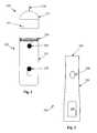
- FIG. 2is one view of an ophthalmic medical device including a disposable tip segment and a limited reuse assembly according to an embodiment of the present invention.
- FIG. 3is another embodiment of a limited reuse assembly according to the principles of the present invention.
- FIG. 4is cross section view of a disposable tip segment and a limited reuse assembly according to an embodiment of the present invention.
- FIGS. 5A and 5Bare exploded cross section views of disposable tip segments for an ophthalmic medical device according to an embodiment of the present invention.
- FIG. 6is a cross section view of an ophthalmic injection device according to the principles of the present invention.
- FIG. 7is a flow chart of one method of delivering a substance into an eye using a shape memory alloy.
- FIG. 8is a flow chart of one method of delivering a substance into an eye using a shape memory alloy.
- FIG. 2is one view of an ophthalmic medical device including a disposable tip segment and a limited reuse assembly according to an embodiment of the present invention.
- the medical deviceincludes a tip segment 205 and a limited reuse assembly 250 .
- the tip segment 205includes a needle 210 , a housing 215 , and an optional light 275 .
- the limited reuse assembly 250includes a housing 255 , a switch 270 , a lock mechanism 265 , and a threaded portion 260 .
- Tip segment 205is capable of being connected to and removed from limited reuse assembly 250 .
- tip segment 205has a threaded portion on an interior surface of housing 215 that screws onto the threaded portion 260 of limited reuse assembly 250 .
- lock mechanism 265secures tip segment 215 to limited reuse assembly 250 .
- Lock mechanism 265may be in the form of a button, a sliding switch, or a cantilevered mechanism.
- Other mechanisms for connecting tip segment 205 to limited reuse assembly 250such as those involving structural features that mate with each other, are commonly known in the art and are within the scope of the present invention.
- Needle 210is adapted to deliver a substance, such as a drug, into an eye. Needle 210 may be of any commonly known configuration. Preferably, needle 210 is designed such that its thermal characteristics are conducive to the particular drug delivery application. For example, when a heated drug is to be delivered, needle 210 may be relatively short (several millimeters) in length to facilitate proper delivery of the drug.
- Switch 270is adapted to provide an input to the system.
- switch 270may be used to activate the system or to turn on a heater.
- Other switches, buttons, or user-directed control inputsare commonly known and may be employed with limited reuse assembly 250 and/or tip segment 205 .
- Optional light 275is illuminated when tip segment 205 is ready to be used.
- Optional light 275may protrude from housing 215 , or it may be contained within housing 215 , in which case, optional light 275 may be seen through a clear portion of housing 215 .
- optional light 275may be replaced by an indicator, such as a liquid crystal display, segmented display, or other device that indicates a status or condition of disposable tip segment 205 .
- optional light 275may also pulse on and off to indicate other states, such as, but not limited to a system error, fully charged battery, insufficiently charged battery or faulty connection between the tip segment 205 and limited use assembly 250 . While shown on tip segment 205 , optional light 275 or other indicator may be located on limited reuse assembly 250 .
- FIG. 3is another embodiment of a limited reuse assembly according to the principles of the present invention.
- Limited reuse assembly 250includes a button 308 , a display 320 , and a housing 330 .
- Disposable tip segment 205attaches to end 340 of limited reuse assembly 250 .
- Button 308is actuated to provide an input to the system. As with switch 270 , button 308 may activate a heater or other temperature control device or initiate actuation of a plunger.
- Display 320is a liquid crystal display, segmented display, or other device that indicates a status or condition of disposable tip segment 205 or limited reuse assembly 250 .
- FIG. 4is cross section view of a disposable tip segment and a limited reuse assembly according to an embodiment of the present invention.
- FIG. 4shows how tip segment 205 interfaces with limited reuse assembly 250 .
- tip segment 205includes dispensing chamber housing 425 , tip segment housing 215 , thermal sensor 460 , needle 210 , dispensing chamber 405 , interface 530 , and tip interface connector 453 .
- Limited reuse assembly 250includes power source 505 , controller 305 , limited reuse assembly housing 255 , interface 535 , and limited reuse assembly interface connector 553 .
- dispensing chamber housing 425is tubular or cylindrical in shape and is made of a shape memory alloy (“SMA”).
- SMAshape memory alloys
- Nitinol (a nickel-titanium alloy) alloyshold a deformed shape at room temperature. When heated to a higher temperature, the SMA reverts to its non-deformed shape.
- a shape memory alloyalso known as a smart alloy or memory metal
- a shape memory alloyis a metal that “remembers” its geometry. After an SMA has been deformed from its original atomic configuration, it regains its original geometry by itself during heating.
- SMAsingle crystal structures
- Cu—Tinickel-titanium alloys.
- the temperatures at which the SMA changes its crystallographic structureare characteristic of the alloy, and can be tuned by varying the elemental ratios.
- the Nitinolis in a deformed shape at room temperature. In this deformed shape, the Nitinol has a martenistic crystal structure. In this deformed shape, dispensing chamber 405 has a higher volume and can hold a substance. When a current is passed through dispensing chamber housing 425 , its temperature rises. When the temperature of the Nitinol dispensing chamber housing 425 reaches 60 or 70 degrees Celsius, the Nitinol will revert to its non-deformed shape. In this process, the Nitinol changes from a martenistic crystal structure to an austenic crystal structure.
- dispensing chamber 405has a lower volume than in the deformed shape. Therefore, a current can be passed through dispensing chamber housing 425 to initially heat a substance in it, and then to change the shape of dispensing chamber 405 to expel that substance.
- Needle 210is fluidly coupled to dispensing chamber 405 . As such, a substance contained in dispensing chamber 405 can pass through needle 210 and into an eye.
- Interface 530connects dispensing chamber housing 425 with tip interface connector 453 .
- Optional thermal sensor 460provides temperature information to assist in controlling the operation of dispensing chamber housing 425 .
- Thermal sensor 460may be located near dispensing chamber housing 425 and measure a temperature near dispensing chamber housing 425 or may be located in thermal contact with dispensing chamber housing 425 , in which case it measures a temperature of dispensing chamber housing 425 .
- Thermal sensor 460may be any of a number of different devices that can provide temperature information.
- thermal sensor 460may be a thermocouple or a resistive device whose resistance varies with temperature. Thermal sensor is also electrically coupled to interface 530 or other similar interface.
- power source 505is typically a rechargeable battery, such as a lithium ion battery, although other types of batteries may be employed. In addition, any other type of power cell is appropriate for power source 505 .
- Power source 505provides current to dispensing chamber housing 425 to heat it and change its shape.
- power source 505can be removed from housing 255 through a door or other similar feature (not shown).
- Controller 305is typically an integrated circuit with power, input, and output pins capable of performing logic functions.
- controller 305is a targeted device controller.
- controller 305performs specific control functions targeted to a specific device or component, such as a temperature control device or a power supply.
- a temperature control device controllerhas the basic functionality to control current delivered to dispensing chamber housing 425 .
- controller 305is a microprocessor.
- controller 305is programmable so that it can function to control more than one component of the device.
- controller 305is not a programmable microprocessor, but instead is a special purpose controller configured to control different components that perform different functions. While depicted as one component in FIG. 4 , controller 305 may be made of many different components or integrated circuits.
- Controller 305is connected via interface 535 to limited reuse assembly interface connector 553 .
- Limited reuse assembly interface connector 553is located on a top surface of limited reuse assembly housing 255 . In this manner, limited reuse assembly interface connector 553 is adapted to be connected with tip interface connector 453 to provide an electrical connection between tip segment 205 and limited reuse assembly 250 .
- controller 305An interface between power source 505 and controller 305 allows controller 305 to control operation of power source 505 .
- controller 305may control the charging and the discharging of power source 505 when power source 505 is a rechargeable battery.
- controller 305controls the operation of dispensing chamber housing 425 .
- Controller 305directs current from power source 505 to dispensing chamber housing 425 .
- dispensing chamber housing 425is made of Nitinol, a first current is sent to it to increase its temperature and heat a substance contained in dispensing chamber 405 .
- a second, higher currentis subsequently sent to dispensing chamber housing 425 to cause it to change its shape and expel the substance through needle 210 .
- a substance to be delivered into an eyetypically a drug suspended in a phase transition compound, is located in dispensing chamber 405 .
- the drug and phase transition compoundare contacted by the inner surface of dispensing chamber housing 425 .
- the phase transition compoundis in a solid or semi-solid state at lower temperatures and in a more liquid state at higher temperatures.
- Such a compoundcan be heated by the application of current to dispensing chamber housing 425 to a more liquid state and injected into the eye where it forms a bolus that erodes over time.
- the substance located in dispensing chamber 405is a drug that is preloaded into the dispensing chamber.
- tip segment 205is appropriate as a single use consumable product.
- Such a disposable productcan be assembled at a factory with a dosage of a drug installed.
- FIGS. 5A and 5Bare exploded cross section views of disposable tip segments for an ophthalmic medical device according to an embodiment of the present invention.
- dispensing chamber housing 425is in its deformed shape (its crystalline structure is martenistic).
- dispensing chamber housingis in its non-deformed shape (its crystalline structure is austenic).
- an optional lueris also picture to secure needle 210 .
- a first currentis applied to dispensing chamber housing 425 .
- This first currentis less than that required to heat dispensing chamber housing 425 to a point at which it changes shape.
- this first currentheats dispensing chamber housing 425 to a temperature above room temperature but below the temperature at which it changes shape. In this manner, a substance located in dispensing chamber 425 is heated because it is in thermal contact with the interior surface of dispensing chamber housing 425 .
- a first currentmay raise the temperature of dispensing chamber housing 425 to 50 degrees Celsius. At this temperature, a phase transition compound located in dispensing chamber housing can be “melted” to a more liquid state or to a viscosity suitable for injection into an eye. However, at this point, the dispensing chamber housing maintains its deformed shape (and the dispensing chamber 405 has a higher volume).
- a second currentcan be applied to raise the temperature of dispensing chamber housing 425 (made of Nitinol) to above 60 or 70 degrees Celsius. At this temperature, dispensing chamber housing 425 changes shape as depicted in FIG. 5B . The volume of dispensing chamber 405 is reduced, thus expelling a substance 559 that was contained in dispensing chamber 405 . In other words, after the phase transition compound located in dispensing chamber 405 is heated, the second current causes the volume of dispensing chamber 405 to decrease and expel the phase transition compound through needle 210 and into an eye.
- the first current applied to the dispensing chamber housing 425can be regulated to control the temperature of the substance contained in dispensing chamber 405 .
- the amount of currenttypically DC current
- the more current applied to dispensing chamber housing 425the greater its temperature.
- Thermal sensor 460provides temperature information to controller 305 , so that it can control the amount of current sent to dispensing chamber housing 425 .
- Controller 305may employ any of a number of different control algorithms, such as, for example, a PID algorithm.
- the second current applied to dispensing chamber housing 425can be regulated to control a dosage and rate of delivery of the substance in dispensing chamber 405 .
- a shape metal alloysuch as Nitinol, may transform its shape gradually over a temperature range.
- the shape of dispensing chamber 425may change over a range of 5 or 10 degrees Celsius.
- the precise control of the current applied to dispensing chamber housing 425results in the precise control of the temperature of dispensing chamber housing 425 . In this manner, the transition of dispensing chamber housing 425 from a deformed state to a non-deformed state can be controlled.
- the control of the change in shaperesults in control of the rate of delivery of the substance.
- FIG. 6is a cross section view of an ophthalmic injection device according to the principles of the present invention.
- the injection deviceis integrated into a single unit.
- the single piece device of FIG. 6operates in the same manner as the two piece device previously described.
- the deviceincludes dispensing chamber housing 425 , dispensing chamber 405 , needle 210 , thermal sensor 460 , interface 536 , controller 305 , power source 505 , and housing 216 .
- a single interface 536is used instead of two separate interfaces ( 530 and 535 ) and two separate connectors ( 453 and 553 ).
- Housing 216encloses the components pictured.
- FIG. 7is a method of delivering a substance into an eye using a shape memory alloy.
- a first input indicating that a substance is to be heatedis received.
- a first currentis directed to an SMA dispensing chamber housing to heat the substance in the dispensing chamber.
- a second inputis received indicating that the substance is to be delivered.
- a second currentis directed to the SMA dispensing chamber housing to change its shape and dispense the substance.
- FIG. 8is a method of delivering a substance into an eye using a shape memory alloy.
- a connection between a tip segment and a limited reuse assemblyis recognized.
- a first input indicating that a substance is to be heatedis received.
- a first currentis sent to the dispensing chamber housing.
- a determinationis made as to whether the substance has reached the proper temperature. If the substance has not reached the proper temperature, then in 825 the first current is controlled to properly heat the substance. If the substance has reached the proper temperature, then in 830 , a second current is sent to the dispensing chamber housing to change its shape and deliver the substance.
- a determinationis made as to whether the proper dosage has been delivered. If the proper dosage has been delivered, then in 840 an indication that the substance has been delivered is provided. If the proper dosage has not been delivered, then in 845 a failure indication is provided.
- the present inventionprovides an improved system and methods for delivering precise volumes of a substance into an eye.
- the present inventionprovides a dispensing chamber housing made of a shape memory alloy that can heat and expel a substance.
- a disposable tip segmentthat interfaces with a limited reuse assembly is employed.
- a single unitis employed.
Landscapes
- Health & Medical Sciences (AREA)
- Life Sciences & Earth Sciences (AREA)
- Engineering & Computer Science (AREA)
- Biomedical Technology (AREA)
- Heart & Thoracic Surgery (AREA)
- Animal Behavior & Ethology (AREA)
- General Health & Medical Sciences (AREA)
- Public Health (AREA)
- Veterinary Medicine (AREA)
- Vascular Medicine (AREA)
- Anesthesiology (AREA)
- Hematology (AREA)
- Ophthalmology & Optometry (AREA)
- Infusion, Injection, And Reservoir Apparatuses (AREA)
Abstract
Description
Claims (10)
Priority Applications (1)
| Application Number | Priority Date | Filing Date | Title |
|---|---|---|---|
| US11/752,064US7862540B2 (en) | 2006-05-17 | 2007-05-22 | Ophthalmic injection device using shape memory alloy |
Applications Claiming Priority (5)
| Application Number | Priority Date | Filing Date | Title |
|---|---|---|---|
| US11/435,906US20070270750A1 (en) | 2006-05-17 | 2006-05-17 | Drug delivery device |
| US92149806P | 2006-10-16 | 2006-10-16 | |
| US92149706P | 2006-10-16 | 2006-10-16 | |
| US92149906P | 2006-10-16 | 2006-10-16 | |
| US11/752,064US7862540B2 (en) | 2006-05-17 | 2007-05-22 | Ophthalmic injection device using shape memory alloy |
Related Parent Applications (2)
| Application Number | Title | Priority Date | Filing Date |
|---|---|---|---|
| US11/435,906Continuation-In-PartUS20070270750A1 (en) | 2006-05-17 | 2006-05-17 | Drug delivery device |
| US92149706PContinuation-In-Part | 2006-05-17 | 2006-10-16 |
Publications (2)
| Publication Number | Publication Date |
|---|---|
| US20070270777A1 US20070270777A1 (en) | 2007-11-22 |
| US7862540B2true US7862540B2 (en) | 2011-01-04 |
Family
ID=46327932
Family Applications (1)
| Application Number | Title | Priority Date | Filing Date |
|---|---|---|---|
| US11/752,064Expired - Fee RelatedUS7862540B2 (en) | 2006-05-17 | 2007-05-22 | Ophthalmic injection device using shape memory alloy |
Country Status (1)
| Country | Link |
|---|---|
| US (1) | US7862540B2 (en) |
Cited By (8)
| Publication number | Priority date | Publication date | Assignee | Title |
|---|---|---|---|---|
| US20140271273A1 (en)* | 2013-03-15 | 2014-09-18 | Novartis Ag | Handheld ocular aspiration tool |
| WO2014185825A1 (en)* | 2013-05-17 | 2014-11-20 | Общество С Ограниченной Ответственностью "Научно-Производственный Центр "Амфион" | Hydrogel material based on cross-linked polyvinyl alcohol |
| US9545337B2 (en) | 2013-03-15 | 2017-01-17 | Novartis Ag | Acoustic streaming glaucoma drainage device |
| US9693896B2 (en) | 2013-03-15 | 2017-07-04 | Novartis Ag | Systems and methods for ocular surgery |
| US9750638B2 (en) | 2013-03-15 | 2017-09-05 | Novartis Ag | Systems and methods for ocular surgery |
| US9915274B2 (en) | 2013-03-15 | 2018-03-13 | Novartis Ag | Acoustic pumps and systems |
| US9962288B2 (en) | 2013-03-07 | 2018-05-08 | Novartis Ag | Active acoustic streaming in hand piece for occlusion surge mitigation |
| US10182940B2 (en) | 2012-12-11 | 2019-01-22 | Novartis Ag | Phacoemulsification hand piece with integrated aspiration and irrigation pump |
Families Citing this family (21)
| Publication number | Priority date | Publication date | Assignee | Title |
|---|---|---|---|---|
| US7431710B2 (en) | 2002-04-08 | 2008-10-07 | Glaukos Corporation | Ocular implants with anchors and methods thereof |
| US8827945B2 (en) | 2006-11-06 | 2014-09-09 | Aardvark Medical, Inc. | Irrigation and aspiration devices and methods |
| US20090227979A1 (en)* | 2008-03-07 | 2009-09-10 | Sanchez Jr Robert J | Drug Level Sensor for Injection Device |
| US10206813B2 (en) | 2009-05-18 | 2019-02-19 | Dose Medical Corporation | Implants with controlled drug delivery features and methods of using same |
| WO2010135369A1 (en) | 2009-05-18 | 2010-11-25 | Dose Medical Corporation | Drug eluting ocular implant |
| WO2012071476A2 (en) | 2010-11-24 | 2012-05-31 | David Haffner | Drug eluting ocular implant |
| GB2490721B (en)* | 2011-05-12 | 2017-03-01 | Owen Mumford Ltd | Injection devices |
| US10245178B1 (en) | 2011-06-07 | 2019-04-02 | Glaukos Corporation | Anterior chamber drug-eluting ocular implant |
| EP3677229A1 (en) | 2014-05-29 | 2020-07-08 | Glaukos Corporation | Implants with controlled drug delivery features |
| CA2959162C (en)* | 2014-08-28 | 2023-02-28 | Unitract Syringe Pty Ltd | Sensor systems for drug delivery devices |
| MX2017006267A (en) | 2014-11-18 | 2017-08-14 | Lilly Co Eli | Thermal locking mechanism for a medication delivery device. |
| US11925578B2 (en) | 2015-09-02 | 2024-03-12 | Glaukos Corporation | Drug delivery implants with bi-directional delivery capacity |
| US11564833B2 (en) | 2015-09-25 | 2023-01-31 | Glaukos Corporation | Punctal implants with controlled drug delivery features and methods of using same |
| CN109937025B (en) | 2016-04-20 | 2022-07-29 | 多斯医学公司 | Delivery device for bioabsorbable ocular drugs |
| US12343511B1 (en) | 2024-04-19 | 2025-07-01 | Genzyme Corporation | Medicament delivery device |
| US12337160B1 (en) | 2024-04-19 | 2025-06-24 | Genzyme Corporation | Medicament delivery device |
| US12357758B1 (en)* | 2024-04-19 | 2025-07-15 | Genzyme Corporation | Medicament delivery device |
| US12377226B1 (en) | 2024-04-19 | 2025-08-05 | Genzyme Corporation | Medicament delivery device |
| US12343505B1 (en) | 2024-04-19 | 2025-07-01 | Genzyme Corporation | Medicament delivery device |
| US12434008B1 (en) | 2025-02-26 | 2025-10-07 | Genzyme Corporation | Lock ring for a medicament delivery device |
| US12420017B1 (en) | 2025-02-26 | 2025-09-23 | Genzyme Corporation | Damping device for a medicament delivery device |
Citations (75)
| Publication number | Priority date | Publication date | Assignee | Title |
|---|---|---|---|---|
| US1252614A (en) | 1917-04-24 | 1918-01-08 | Oscar H Pieper | Hot-air syringe. |
| US3089815A (en) | 1951-10-11 | 1963-05-14 | Lieb Hans | Injectable pharmaceutical preparation, and a method of making same |
| US3608549A (en) | 1970-01-15 | 1971-09-28 | Merrill Edward Wilson | Method of administering drugs and capsule therefor |
| US3892537A (en) | 1973-11-28 | 1975-07-01 | Corning Glass Works | Preload means for ceramic substrate in exhaust gas purifiers |
| US3982537A (en) | 1974-12-30 | 1976-09-28 | Louis Bucalo | Dynamic implants and method for implanting the same |
| US4007742A (en) | 1974-06-03 | 1977-02-15 | Surgical Design Corporation. | Surgical system for controlling the infusion of fluid to and the evacuation of fluid and material from an operating field |
| US4030499A (en) | 1974-12-30 | 1977-06-21 | Louis Bucalo | Method and apparatus for providing living beings with absorbable implants |
| US4054138A (en) | 1974-12-30 | 1977-10-18 | Louis Bucalo | Implants for acting on living beings |
| US4122850A (en) | 1976-06-07 | 1978-10-31 | Louis Bucalo | Apparatus for providing living beings with absorbable implants |
| GB1551767A (en) | 1975-05-27 | 1979-08-30 | Bucalo L | Implantment of living beings or the like subjects |
| US4184510A (en) | 1977-03-15 | 1980-01-22 | Fibra-Sonics, Inc. | Valued device for controlling vacuum in surgery |
| US4246932A (en) | 1979-10-18 | 1981-01-27 | Burron Medical, Inc. | Multiple additive valve assembly |
| US4265618A (en) | 1977-09-09 | 1981-05-05 | Solar Energy Technology, Inc. | Electrically heated endodontic syringe for injecting thermoplastic material into a root canal cavity |
| US4357136A (en) | 1977-09-09 | 1982-11-02 | Solar Energy Technology, Inc. | Method for filling a root canal |
| WO1982003761A1 (en) | 1981-05-04 | 1982-11-11 | Energy Techn Inc Solar | Syringe for obturation of root canal cavities |
| US4392827A (en) | 1981-11-04 | 1983-07-12 | Howard Martin | Self-contained root canal heated condenser dental instrument |
| US4474752A (en) | 1983-05-16 | 1984-10-02 | Merck & Co., Inc. | Drug delivery system utilizing thermosetting gels |
| US4484915A (en) | 1983-03-28 | 1984-11-27 | Tartaglia John A | Medical syringe |
| US4582488A (en) | 1984-04-27 | 1986-04-15 | Newman Martin H | Dental materials dispenser and applicator |
| WO1987000029A1 (en) | 1985-06-26 | 1987-01-15 | Pitz Richard J | Root canal implant-proximity indicative-delivery means |
| US4684344A (en) | 1986-04-11 | 1987-08-04 | Nalge Company | Electrically powered and heated endodontic syringe |
| US4704088A (en) | 1984-04-27 | 1987-11-03 | Newman Martin H | Dental materials dispenser and applicator |
| US4713446A (en) | 1985-09-06 | 1987-12-15 | Minnesota Mining And Manufacturing Company | Viscoelastic collagen solution for ophthalmic use and method of preparation |
| US4795423A (en) | 1980-04-14 | 1989-01-03 | Thomas Jefferson University | Oxygenated perfluorinated perfusion of the ocular globe to treat ischemic retinopathy |
| US4830855A (en) | 1987-11-13 | 1989-05-16 | Landec Labs, Inc. | Temperature-controlled active agent dispenser |
| EP0348146A1 (en) | 1988-06-21 | 1989-12-27 | Alcon Laboratories, Inc. | Apparatus for injecting viscous fluid into the eye |
| EP0398394A2 (en) | 1983-11-15 | 1990-11-22 | KAMEN, Dean L. | Reservoir assembly for removable engagement with a motor drive |
| US4992045A (en) | 1987-04-01 | 1991-02-12 | Dentsply Research & Development Corp. | Battery powered condenser for root canals |
| US5120307A (en) | 1988-06-21 | 1992-06-09 | Alcon Laboratories, Inc. | Method for injecting viscous fluid into the eye to life retinal membrane |
| US5336175A (en) | 1992-10-29 | 1994-08-09 | Mames Robert N | Method for the treatment of retinal detachments |
| US5360413A (en) | 1991-12-06 | 1994-11-01 | Filtertek, Inc. | Needleless access device |
| US5370630A (en) | 1993-11-12 | 1994-12-06 | Smidebush; Michael J. | Device for injection of fluidic materials into body tissue |
| US5476511A (en) | 1992-05-04 | 1995-12-19 | Allergan, Inc. | Subconjunctival implants for ocular drug delivery |
| US5487725A (en) | 1994-05-12 | 1996-01-30 | Syntec, Inc. | Pneumatic vitrectomy for retinal attachment |
| WO1996003978A1 (en) | 1994-08-04 | 1996-02-15 | Quadrant Holdings Cambridge Limited | Solid delivery systems for controlled release of molecules incorporated therein and methods of making same |
| US5582595A (en) | 1995-09-28 | 1996-12-10 | Habley Medical Technology Corporation | Aspirating syringe having a plunger guide for a reciprocating plunger assembly |
| US5620700A (en) | 1990-10-30 | 1997-04-15 | Alza Corporation | Injectable drug delivery system and method |
| US5743886A (en) | 1994-02-15 | 1998-04-28 | Lawrence A. Lynn | Sequential medical fluid aspiration and injection system and method |
| US5773019A (en) | 1995-09-27 | 1998-06-30 | The University Of Kentucky Research Foundation | Implantable controlled release device to deliver drugs directly to an internal portion of the body |
| US5783205A (en) | 1990-10-30 | 1998-07-21 | Alza Corporation | Injectable drug delivery system and method |
| US5824072A (en) | 1993-11-15 | 1998-10-20 | Oculex Pharmaceuticals, Inc. | Biocompatible ocular implants |
| US5860949A (en) | 1996-12-20 | 1999-01-19 | Chen; Jen-Yie | Volume homeostatic fluid-fluid exchanger |
| WO1999033853A2 (en) | 1997-12-23 | 1999-07-08 | Quadrant Holdings Cambridge Limited | Carbohydrates, useful in solid delivery systems |
| US5928663A (en) | 1997-07-30 | 1999-07-27 | Vitrophage, Inc. | Intraocular perfluorcarbon compositions and surgical methods of using same |
| US5984889A (en) | 1996-02-23 | 1999-11-16 | Allergan Sales, Inc. | Apparatus and method for delivering viscoelastic material to an eye |
| WO2001010482A1 (en) | 1999-08-05 | 2001-02-15 | Biocardia, Inc. | A system and method for delivering thermally sensitive and reverse-thermal gelation matrials |
| US6210357B1 (en) | 1998-07-06 | 2001-04-03 | Robert E Morris | Apparatus for performing surgery inside the human retina using fluidic internal limiting membrane (ILM) separation (films) |
| US6270343B1 (en) | 2000-01-07 | 2001-08-07 | Howard Martin | Endodontic thermal condenser dental instrument |
| US6290690B1 (en) | 1999-06-21 | 2001-09-18 | Alcon Manufacturing, Ltd. | Simultaneous injection and aspiration of viscous fluids in a surgical system |
| US6364865B1 (en) | 1998-11-13 | 2002-04-02 | Elan Pharma International Limited | Drug delivery systems and methods |
| US6372245B1 (en) | 1992-12-29 | 2002-04-16 | Insite Vision Incorporated | Plasticized bioerodible controlled delivery system |
| US20020055720A1 (en) | 2000-05-18 | 2002-05-09 | Dentsply Research & Development Corp. | Fluid material dispensing syringe |
| US6413245B1 (en) | 1999-10-21 | 2002-07-02 | Alcon Universal Ltd. | Sub-tenon drug delivery |
| US6419656B1 (en) | 1999-03-19 | 2002-07-16 | Arzneimittel Gmbh Apotheker Vetter & Ravensburg | Medical syringe with braked step-advance plunger |
| US6436143B1 (en) | 1999-02-22 | 2002-08-20 | Anthony C. Ross | Method and apparatus for treating intervertebral disks |
| US6520930B2 (en) | 1999-11-24 | 2003-02-18 | Medrad, Inc. | Injectors, injector systems and injector control |
| US20030055380A1 (en) | 2001-09-19 | 2003-03-20 | Flaherty J. Christopher | Plunger for patient infusion device |
| US6585700B1 (en) | 2000-10-05 | 2003-07-01 | Medrad, Inc. | Syringe, syringe plunger and attachment mechanism for front loading medical injector |
| US6595979B1 (en) | 2001-07-10 | 2003-07-22 | Myocardial Therapeutics, Inc. | Methods for sterile aspiration/reinjection of bodily fluid |
| US6635267B1 (en) | 1998-11-10 | 2003-10-21 | Denki Kagaku Kogyo Kabushiki Kaisha | Hyaluronic acid gel, process for the preparation thereof and medical materials containing the same |
| US6645179B1 (en) | 1999-07-06 | 2003-11-11 | Nihon Chemical Research Co., Ltd. | Injection syringe |
| US20040039253A1 (en) | 2002-08-20 | 2004-02-26 | Peyman Gholam A. | Treatment of retinal detachment |
| US20040052761A1 (en) | 2002-07-19 | 2004-03-18 | Brent Vernon | Localized delivery system for cancer drugs, phenstatin, using N-isopropylacrylamide |
| US20040133155A1 (en) | 2000-08-30 | 2004-07-08 | Varner Sign Erickson | Devices for intraocular drug delivery |
| US20040176720A1 (en) | 2002-08-31 | 2004-09-09 | Urs Kipfer | Device for administering a liquid solution of an active substance |
| US20040210200A1 (en) | 2003-04-16 | 2004-10-21 | Gerondale Scott J. | Controlled volume injection/aspiration device |
| US20040231667A1 (en) | 2001-06-11 | 2004-11-25 | Horton Andrew Paul | Medicament dispenser |
| US20050065477A1 (en) | 2003-09-19 | 2005-03-24 | Stefan Jost | Device for dispensing an injectable product in doses |
| US20050177137A1 (en) | 2002-08-31 | 2005-08-11 | Urs Kipfer | Administering device with temperature sensor |
| US6940209B2 (en) | 2003-09-08 | 2005-09-06 | New Scale Technologies | Ultrasonic lead screw motor |
| US6981499B2 (en)* | 1999-12-11 | 2006-01-03 | Glaxo Group Limited | Medicament dispenser |
| US6991457B2 (en) | 2003-05-06 | 2006-01-31 | Aseptico, Inc. | Endodontic obturator with disposable cartridge |
| US20060047250A1 (en) | 2004-08-30 | 2006-03-02 | Hickingbotham Dyson W | Fluid delivery device |
| WO2006050008A1 (en) | 2003-06-20 | 2006-05-11 | Allergan, Inc. | Needleless applicator system and method for application of medicament to the back of an eye |
| US7176030B2 (en) | 2002-06-17 | 2007-02-13 | O.R. Solutions, Inc. | Method and apparatus for ensuring sterility of disposable medical items used with medical equipment |
Family Cites Families (1)
| Publication number | Priority date | Publication date | Assignee | Title |
|---|---|---|---|---|
| US6372246B1 (en)* | 1998-12-16 | 2002-04-16 | Ortho-Mcneil Pharmaceutical, Inc. | Polyethylene glycol coating for electrostatic dry deposition of pharmaceuticals |
- 2007
- 2007-05-22USUS11/752,064patent/US7862540B2/ennot_activeExpired - Fee Related
Patent Citations (80)
| Publication number | Priority date | Publication date | Assignee | Title |
|---|---|---|---|---|
| US1252614A (en) | 1917-04-24 | 1918-01-08 | Oscar H Pieper | Hot-air syringe. |
| US3089815A (en) | 1951-10-11 | 1963-05-14 | Lieb Hans | Injectable pharmaceutical preparation, and a method of making same |
| US3608549A (en) | 1970-01-15 | 1971-09-28 | Merrill Edward Wilson | Method of administering drugs and capsule therefor |
| US3892537A (en) | 1973-11-28 | 1975-07-01 | Corning Glass Works | Preload means for ceramic substrate in exhaust gas purifiers |
| US4007742A (en) | 1974-06-03 | 1977-02-15 | Surgical Design Corporation. | Surgical system for controlling the infusion of fluid to and the evacuation of fluid and material from an operating field |
| US3982537A (en) | 1974-12-30 | 1976-09-28 | Louis Bucalo | Dynamic implants and method for implanting the same |
| US4030499A (en) | 1974-12-30 | 1977-06-21 | Louis Bucalo | Method and apparatus for providing living beings with absorbable implants |
| US4054138A (en) | 1974-12-30 | 1977-10-18 | Louis Bucalo | Implants for acting on living beings |
| GB1551767A (en) | 1975-05-27 | 1979-08-30 | Bucalo L | Implantment of living beings or the like subjects |
| US4122850A (en) | 1976-06-07 | 1978-10-31 | Louis Bucalo | Apparatus for providing living beings with absorbable implants |
| US4184510A (en) | 1977-03-15 | 1980-01-22 | Fibra-Sonics, Inc. | Valued device for controlling vacuum in surgery |
| US4265618A (en) | 1977-09-09 | 1981-05-05 | Solar Energy Technology, Inc. | Electrically heated endodontic syringe for injecting thermoplastic material into a root canal cavity |
| US4357136A (en) | 1977-09-09 | 1982-11-02 | Solar Energy Technology, Inc. | Method for filling a root canal |
| US4246932A (en) | 1979-10-18 | 1981-01-27 | Burron Medical, Inc. | Multiple additive valve assembly |
| US4795423A (en) | 1980-04-14 | 1989-01-03 | Thomas Jefferson University | Oxygenated perfluorinated perfusion of the ocular globe to treat ischemic retinopathy |
| WO1982003761A1 (en) | 1981-05-04 | 1982-11-11 | Energy Techn Inc Solar | Syringe for obturation of root canal cavities |
| US4392827A (en) | 1981-11-04 | 1983-07-12 | Howard Martin | Self-contained root canal heated condenser dental instrument |
| US4484915A (en) | 1983-03-28 | 1984-11-27 | Tartaglia John A | Medical syringe |
| US4474752A (en) | 1983-05-16 | 1984-10-02 | Merck & Co., Inc. | Drug delivery system utilizing thermosetting gels |
| EP0398394A2 (en) | 1983-11-15 | 1990-11-22 | KAMEN, Dean L. | Reservoir assembly for removable engagement with a motor drive |
| US4582488A (en) | 1984-04-27 | 1986-04-15 | Newman Martin H | Dental materials dispenser and applicator |
| US4704088A (en) | 1984-04-27 | 1987-11-03 | Newman Martin H | Dental materials dispenser and applicator |
| WO1987000029A1 (en) | 1985-06-26 | 1987-01-15 | Pitz Richard J | Root canal implant-proximity indicative-delivery means |
| US4713446A (en) | 1985-09-06 | 1987-12-15 | Minnesota Mining And Manufacturing Company | Viscoelastic collagen solution for ophthalmic use and method of preparation |
| US4684344A (en) | 1986-04-11 | 1987-08-04 | Nalge Company | Electrically powered and heated endodontic syringe |
| US4992045A (en) | 1987-04-01 | 1991-02-12 | Dentsply Research & Development Corp. | Battery powered condenser for root canals |
| US4830855A (en) | 1987-11-13 | 1989-05-16 | Landec Labs, Inc. | Temperature-controlled active agent dispenser |
| US5120307A (en) | 1988-06-21 | 1992-06-09 | Alcon Laboratories, Inc. | Method for injecting viscous fluid into the eye to life retinal membrane |
| US5066276A (en) | 1988-06-21 | 1991-11-19 | Alcon Laboratories, Inc. | Method and apparatus for injecting viscous fluid into the eye to lift pre-retinal and post-retinal membrane with linear pressure control |
| EP0348146A1 (en) | 1988-06-21 | 1989-12-27 | Alcon Laboratories, Inc. | Apparatus for injecting viscous fluid into the eye |
| US5328481A (en) | 1988-06-21 | 1994-07-12 | Alcon Laboratories, Inc. | Method for injecting viscous fluid into the eye to lift retinal membrane |
| US5783205A (en) | 1990-10-30 | 1998-07-21 | Alza Corporation | Injectable drug delivery system and method |
| US5620700A (en) | 1990-10-30 | 1997-04-15 | Alza Corporation | Injectable drug delivery system and method |
| US5360413A (en) | 1991-12-06 | 1994-11-01 | Filtertek, Inc. | Needleless access device |
| US5476511A (en) | 1992-05-04 | 1995-12-19 | Allergan, Inc. | Subconjunctival implants for ocular drug delivery |
| US5336175A (en) | 1992-10-29 | 1994-08-09 | Mames Robert N | Method for the treatment of retinal detachments |
| US6372245B1 (en) | 1992-12-29 | 2002-04-16 | Insite Vision Incorporated | Plasticized bioerodible controlled delivery system |
| US5370630A (en) | 1993-11-12 | 1994-12-06 | Smidebush; Michael J. | Device for injection of fluidic materials into body tissue |
| US5824072A (en) | 1993-11-15 | 1998-10-20 | Oculex Pharmaceuticals, Inc. | Biocompatible ocular implants |
| US5743886A (en) | 1994-02-15 | 1998-04-28 | Lawrence A. Lynn | Sequential medical fluid aspiration and injection system and method |
| US5487725A (en) | 1994-05-12 | 1996-01-30 | Syntec, Inc. | Pneumatic vitrectomy for retinal attachment |
| WO1996003978A1 (en) | 1994-08-04 | 1996-02-15 | Quadrant Holdings Cambridge Limited | Solid delivery systems for controlled release of molecules incorporated therein and methods of making same |
| US5773019A (en) | 1995-09-27 | 1998-06-30 | The University Of Kentucky Research Foundation | Implantable controlled release device to deliver drugs directly to an internal portion of the body |
| US5582595A (en) | 1995-09-28 | 1996-12-10 | Habley Medical Technology Corporation | Aspirating syringe having a plunger guide for a reciprocating plunger assembly |
| US5984889A (en) | 1996-02-23 | 1999-11-16 | Allergan Sales, Inc. | Apparatus and method for delivering viscoelastic material to an eye |
| US5860949A (en) | 1996-12-20 | 1999-01-19 | Chen; Jen-Yie | Volume homeostatic fluid-fluid exchanger |
| US5928663A (en) | 1997-07-30 | 1999-07-27 | Vitrophage, Inc. | Intraocular perfluorcarbon compositions and surgical methods of using same |
| WO1999033853A2 (en) | 1997-12-23 | 1999-07-08 | Quadrant Holdings Cambridge Limited | Carbohydrates, useful in solid delivery systems |
| US6210357B1 (en) | 1998-07-06 | 2001-04-03 | Robert E Morris | Apparatus for performing surgery inside the human retina using fluidic internal limiting membrane (ILM) separation (films) |
| US6635267B1 (en) | 1998-11-10 | 2003-10-21 | Denki Kagaku Kogyo Kabushiki Kaisha | Hyaluronic acid gel, process for the preparation thereof and medical materials containing the same |
| US6364865B1 (en) | 1998-11-13 | 2002-04-02 | Elan Pharma International Limited | Drug delivery systems and methods |
| US6436143B1 (en) | 1999-02-22 | 2002-08-20 | Anthony C. Ross | Method and apparatus for treating intervertebral disks |
| US6419656B1 (en) | 1999-03-19 | 2002-07-16 | Arzneimittel Gmbh Apotheker Vetter & Ravensburg | Medical syringe with braked step-advance plunger |
| US6290690B1 (en) | 1999-06-21 | 2001-09-18 | Alcon Manufacturing, Ltd. | Simultaneous injection and aspiration of viscous fluids in a surgical system |
| US6645179B1 (en) | 1999-07-06 | 2003-11-11 | Nihon Chemical Research Co., Ltd. | Injection syringe |
| US6488659B1 (en) | 1999-08-05 | 2002-12-03 | Biocardia, Inc. | System and method for delivering thermally sensitive and reverse-thermal gelation materials |
| WO2001010482A1 (en) | 1999-08-05 | 2001-02-15 | Biocardia, Inc. | A system and method for delivering thermally sensitive and reverse-thermal gelation matrials |
| US20030125665A1 (en) | 1999-08-05 | 2003-07-03 | Biocardia, Inc. | System and method for delivering thermally sensitive and reverse-thermal gelation materials |
| US6726654B2 (en) | 1999-08-05 | 2004-04-27 | Biocardia, Inc. | System and method for delivering thermally sensitive and reverse-thermal gelation materials |
| US6413245B1 (en) | 1999-10-21 | 2002-07-02 | Alcon Universal Ltd. | Sub-tenon drug delivery |
| US6520930B2 (en) | 1999-11-24 | 2003-02-18 | Medrad, Inc. | Injectors, injector systems and injector control |
| US6981499B2 (en)* | 1999-12-11 | 2006-01-03 | Glaxo Group Limited | Medicament dispenser |
| US6270343B1 (en) | 2000-01-07 | 2001-08-07 | Howard Martin | Endodontic thermal condenser dental instrument |
| US20020055720A1 (en) | 2000-05-18 | 2002-05-09 | Dentsply Research & Development Corp. | Fluid material dispensing syringe |
| US20040133155A1 (en) | 2000-08-30 | 2004-07-08 | Varner Sign Erickson | Devices for intraocular drug delivery |
| US6585700B1 (en) | 2000-10-05 | 2003-07-01 | Medrad, Inc. | Syringe, syringe plunger and attachment mechanism for front loading medical injector |
| US20040231667A1 (en) | 2001-06-11 | 2004-11-25 | Horton Andrew Paul | Medicament dispenser |
| US6595979B1 (en) | 2001-07-10 | 2003-07-22 | Myocardial Therapeutics, Inc. | Methods for sterile aspiration/reinjection of bodily fluid |
| US20030055380A1 (en) | 2001-09-19 | 2003-03-20 | Flaherty J. Christopher | Plunger for patient infusion device |
| US7176030B2 (en) | 2002-06-17 | 2007-02-13 | O.R. Solutions, Inc. | Method and apparatus for ensuring sterility of disposable medical items used with medical equipment |
| US20040052761A1 (en) | 2002-07-19 | 2004-03-18 | Brent Vernon | Localized delivery system for cancer drugs, phenstatin, using N-isopropylacrylamide |
| US20040039253A1 (en) | 2002-08-20 | 2004-02-26 | Peyman Gholam A. | Treatment of retinal detachment |
| US20040176720A1 (en) | 2002-08-31 | 2004-09-09 | Urs Kipfer | Device for administering a liquid solution of an active substance |
| US20050177137A1 (en) | 2002-08-31 | 2005-08-11 | Urs Kipfer | Administering device with temperature sensor |
| US20040210200A1 (en) | 2003-04-16 | 2004-10-21 | Gerondale Scott J. | Controlled volume injection/aspiration device |
| US6991457B2 (en) | 2003-05-06 | 2006-01-31 | Aseptico, Inc. | Endodontic obturator with disposable cartridge |
| WO2006050008A1 (en) | 2003-06-20 | 2006-05-11 | Allergan, Inc. | Needleless applicator system and method for application of medicament to the back of an eye |
| US6940209B2 (en) | 2003-09-08 | 2005-09-06 | New Scale Technologies | Ultrasonic lead screw motor |
| US20050065477A1 (en) | 2003-09-19 | 2005-03-24 | Stefan Jost | Device for dispensing an injectable product in doses |
| US20060047250A1 (en) | 2004-08-30 | 2006-03-02 | Hickingbotham Dyson W | Fluid delivery device |
Non-Patent Citations (7)
| Title |
|---|
| "Parker: Your Resource For Motion And Fluid Control Components, Systems and Solutions-System Solutions For Life Sciences"; 2003; Aurora Instruments, LLC Brochure; 8 pages. |
| "Parker: Your Resource For Motion And Fluid Control Components, Systems and Solutions—System Solutions For Life Sciences"; 2003; Aurora Instruments, LLC Brochure; 8 pages. |
| "Ultra(TM) 2800 Positive Displacement Dispenser"; 2004; EFD, Inc. Brochure XP 1104 vol. 11.10; 2 pages. |
| "Ultra™ 2800 Positive Displacement Dispenser"; 2004; EFD, Inc. Brochure XP 1104 vol. 11.10; 2 pages. |
| U.S. Appl. No. 11/200,452, filed Aug. 9, 2005, Hopkins. |
| U.S. Appl. No. 11/435,906, filed May 17, 2005, Dacquay et al. |
| U.S. Appl. No. 11/486,870, filed Jul. 14, 2006, Marsh et al. |
Cited By (8)
| Publication number | Priority date | Publication date | Assignee | Title |
|---|---|---|---|---|
| US10182940B2 (en) | 2012-12-11 | 2019-01-22 | Novartis Ag | Phacoemulsification hand piece with integrated aspiration and irrigation pump |
| US9962288B2 (en) | 2013-03-07 | 2018-05-08 | Novartis Ag | Active acoustic streaming in hand piece for occlusion surge mitigation |
| US20140271273A1 (en)* | 2013-03-15 | 2014-09-18 | Novartis Ag | Handheld ocular aspiration tool |
| US9545337B2 (en) | 2013-03-15 | 2017-01-17 | Novartis Ag | Acoustic streaming glaucoma drainage device |
| US9693896B2 (en) | 2013-03-15 | 2017-07-04 | Novartis Ag | Systems and methods for ocular surgery |
| US9750638B2 (en) | 2013-03-15 | 2017-09-05 | Novartis Ag | Systems and methods for ocular surgery |
| US9915274B2 (en) | 2013-03-15 | 2018-03-13 | Novartis Ag | Acoustic pumps and systems |
| WO2014185825A1 (en)* | 2013-05-17 | 2014-11-20 | Общество С Ограниченной Ответственностью "Научно-Производственный Центр "Амфион" | Hydrogel material based on cross-linked polyvinyl alcohol |
Also Published As
| Publication number | Publication date |
|---|---|
| US20070270777A1 (en) | 2007-11-22 |
Similar Documents
| Publication | Publication Date | Title |
|---|---|---|
| US7862540B2 (en) | Ophthalmic injection device using shape memory alloy | |
| US7762981B2 (en) | Temperature release mechanism for injection device | |
| US7674243B2 (en) | Ophthalmic injection device using piezoelectric array | |
| EP2197398B1 (en) | Temperature control device and thermal sensor assembly for medical device | |
| US20070268340A1 (en) | Ophthalmic Injection System and Method Using Piezoelectric Array | |
| US20070270768A1 (en) | Mechanical Linkage Mechanism For Ophthalmic Injection Device | |
| US20100069842A1 (en) | Ceramic Chamber With Integrated Temperature Control Device For Ophthalmic Medical Device | |
| US20090177182A1 (en) | Glass Drug Chamber For Automated Ophthalmic Injection Device | |
| AU2007348610B2 (en) | Temperature control device and thermal sensor assembly for medical device | |
| EP2187850B1 (en) | Thermal coefficient driven drug pellet size for ophthalmic injection | |
| US20090036842A1 (en) | Consumable Activation Lever For Injection Device | |
| EP2187849B1 (en) | Method of preparing an injection device for delivering a rate and temperature - dependent substance into the eye | |
| US20090227979A1 (en) | Drug Level Sensor for Injection Device | |
| EP2088975A2 (en) | Drug casting |
Legal Events
| Date | Code | Title | Description |
|---|---|---|---|
| AS | Assignment | Owner name:ALCON MANUFACTURING, LTD., TEXAS Free format text:ASSIGNMENT OF ASSIGNORS INTEREST;ASSIGNORS:DACQUAY, BRUNO;LIND, CASEY;MARTIN, MIKE;REEL/FRAME:019328/0873;SIGNING DATES FROM 20070514 TO 20070521 Owner name:ALCON MANUFACTURING, LTD., TEXAS Free format text:ASSIGNMENT OF ASSIGNORS INTEREST;ASSIGNORS:DACQUAY, BRUNO;LIND, CASEY;MARTIN, MIKE;SIGNING DATES FROM 20070514 TO 20070521;REEL/FRAME:019328/0873 | |
| AS | Assignment | Owner name:ALCON RESEARCH, LTD., TEXAS Free format text:MERGER;ASSIGNOR:ALCON MANUFACTURING, LTD.;REEL/FRAME:021266/0729 Effective date:20080101 Owner name:ALCON RESEARCH, LTD.,TEXAS Free format text:MERGER;ASSIGNOR:ALCON MANUFACTURING, LTD.;REEL/FRAME:021266/0729 Effective date:20080101 | |
| STCF | Information on status: patent grant | Free format text:PATENTED CASE | |
| FPAY | Fee payment | Year of fee payment:4 | |
| MAFP | Maintenance fee payment | Free format text:PAYMENT OF MAINTENANCE FEE, 8TH YEAR, LARGE ENTITY (ORIGINAL EVENT CODE: M1552) Year of fee payment:8 | |
| AS | Assignment | Owner name:ALCON INC., SWITZERLAND Free format text:CONFIRMATORY DEED OF ASSIGNMENT EFFECTIVE APRIL 8, 2019;ASSIGNOR:NOVARTIS AG;REEL/FRAME:051454/0788 Effective date:20191111 | |
| AS | Assignment | Owner name:ALCON RESEARCH, LLC, TEXAS Free format text:MERGER;ASSIGNOR:ALCON RESEARCH, LTD.;REEL/FRAME:053273/0022 Effective date:20190228 | |
| AS | Assignment | Owner name:ALCON INC., SWITZERLAND Free format text:CONFIRMATORY DEED OF ASSIGNMENT EFFECTIVE APRIL 8, 2019;ASSIGNOR:ALCON RESEARCH, LLC;REEL/FRAME:053293/0484 Effective date:20200619 | |
| FEPP | Fee payment procedure | Free format text:MAINTENANCE FEE REMINDER MAILED (ORIGINAL EVENT CODE: REM.); ENTITY STATUS OF PATENT OWNER: LARGE ENTITY | |
| LAPS | Lapse for failure to pay maintenance fees | Free format text:PATENT EXPIRED FOR FAILURE TO PAY MAINTENANCE FEES (ORIGINAL EVENT CODE: EXP.); ENTITY STATUS OF PATENT OWNER: LARGE ENTITY | |
| STCH | Information on status: patent discontinuation | Free format text:PATENT EXPIRED DUE TO NONPAYMENT OF MAINTENANCE FEES UNDER 37 CFR 1.362 | |
| FP | Lapsed due to failure to pay maintenance fee | Effective date:20230104 |