US7862528B2 - Patella stabilizing method and system - Google Patents
Patella stabilizing method and systemDownload PDFInfo
- Publication number
- US7862528B2 US7862528B2US12/037,320US3732008AUS7862528B2US 7862528 B2US7862528 B2US 7862528B2US 3732008 AUS3732008 AUS 3732008AUS 7862528 B2US7862528 B2US 7862528B2
- Authority
- US
- United States
- Prior art keywords
- patella
- buttress
- strap
- user
- straps
- Prior art date
- Legal status (The legal status is an assumption and is not a legal conclusion. Google has not performed a legal analysis and makes no representation as to the accuracy of the status listed.)
- Active - Reinstated, expires
Links
- 210000004417patellaAnatomy0.000titleclaimsabstractdescription152
- 238000000034methodMethods0.000titleclaimsdescription9
- 230000000087stabilizing effectEffects0.000title1
- 239000003381stabilizerSubstances0.000claimsabstractdescription87
- 210000002414legAnatomy0.000claimsabstractdescription19
- 210000003127kneeAnatomy0.000claimsdescription18
- 210000000689upper legAnatomy0.000claimsdescription10
- 244000309466calfSpecies0.000claimsdescription9
- 230000006835compressionEffects0.000claimsdescription6
- 238000007906compressionMethods0.000claimsdescription6
- 230000003247decreasing effectEffects0.000claimsdescription6
- 230000000399orthopedic effectEffects0.000description10
- 239000000463materialSubstances0.000description7
- 229920001084poly(chloroprene)Polymers0.000description5
- 239000004677NylonSubstances0.000description3
- 229920001778nylonPolymers0.000description3
- 208000027418Wounds and injuryDiseases0.000description2
- 230000006378damageEffects0.000description2
- 238000010586diagramMethods0.000description2
- 208000014674injuryDiseases0.000description2
- 210000003423ankleAnatomy0.000description1
- 230000003190augmentative effectEffects0.000description1
- 230000008901benefitEffects0.000description1
- 239000003086colorantSubstances0.000description1
- 229940079593drugDrugs0.000description1
- 239000003814drugSubstances0.000description1
- 239000013013elastic materialSubstances0.000description1
- 210000001513elbowAnatomy0.000description1
- 230000006872improvementEffects0.000description1
- 230000007246mechanismEffects0.000description1
- 238000012986modificationMethods0.000description1
- 230000004048modificationEffects0.000description1
- 230000008707rearrangementEffects0.000description1
- 238000006467substitution reactionMethods0.000description1
- 238000001356surgical procedureMethods0.000description1
- 229920002994synthetic fiberPolymers0.000description1
Images


Classifications
- A—HUMAN NECESSITIES
- A61—MEDICAL OR VETERINARY SCIENCE; HYGIENE
- A61F—FILTERS IMPLANTABLE INTO BLOOD VESSELS; PROSTHESES; DEVICES PROVIDING PATENCY TO, OR PREVENTING COLLAPSING OF, TUBULAR STRUCTURES OF THE BODY, e.g. STENTS; ORTHOPAEDIC, NURSING OR CONTRACEPTIVE DEVICES; FOMENTATION; TREATMENT OR PROTECTION OF EYES OR EARS; BANDAGES, DRESSINGS OR ABSORBENT PADS; FIRST-AID KITS
- A61F5/00—Orthopaedic methods or devices for non-surgical treatment of bones or joints; Nursing devices ; Anti-rape devices
- A61F5/01—Orthopaedic devices, e.g. long-term immobilising or pressure directing devices for treating broken or deformed bones such as splints, casts or braces
- A61F5/0102—Orthopaedic devices, e.g. long-term immobilising or pressure directing devices for treating broken or deformed bones such as splints, casts or braces specially adapted for correcting deformities of the limbs or for supporting them; Ortheses, e.g. with articulations
- A61F5/0104—Orthopaedic devices, e.g. long-term immobilising or pressure directing devices for treating broken or deformed bones such as splints, casts or braces specially adapted for correcting deformities of the limbs or for supporting them; Ortheses, e.g. with articulations without articulation
- A61F5/0106—Orthopaedic devices, e.g. long-term immobilising or pressure directing devices for treating broken or deformed bones such as splints, casts or braces specially adapted for correcting deformities of the limbs or for supporting them; Ortheses, e.g. with articulations without articulation for the knees
- A—HUMAN NECESSITIES
- A61—MEDICAL OR VETERINARY SCIENCE; HYGIENE
- A61F—FILTERS IMPLANTABLE INTO BLOOD VESSELS; PROSTHESES; DEVICES PROVIDING PATENCY TO, OR PREVENTING COLLAPSING OF, TUBULAR STRUCTURES OF THE BODY, e.g. STENTS; ORTHOPAEDIC, NURSING OR CONTRACEPTIVE DEVICES; FOMENTATION; TREATMENT OR PROTECTION OF EYES OR EARS; BANDAGES, DRESSINGS OR ABSORBENT PADS; FIRST-AID KITS
- A61F5/00—Orthopaedic methods or devices for non-surgical treatment of bones or joints; Nursing devices ; Anti-rape devices
- A61F5/01—Orthopaedic devices, e.g. long-term immobilising or pressure directing devices for treating broken or deformed bones such as splints, casts or braces
- A61F5/0102—Orthopaedic devices, e.g. long-term immobilising or pressure directing devices for treating broken or deformed bones such as splints, casts or braces specially adapted for correcting deformities of the limbs or for supporting them; Ortheses, e.g. with articulations
- A61F2005/0132—Additional features of the articulation
- A61F2005/0172—Additional features of the articulation with cushions
- A61F2005/0176—Additional features of the articulation with cushions supporting the patella
Definitions
- the present inventionrelates to orthopedic joint supports and, more particularly, but not by way of limitation, to an orthopedic support, system and method for supporting a knee with a buttress adapted to be adjustably positioned for proper alignment with a user's patella.
- U.S. Pat. No. 4,494,534 to HudsonThis patent teaches a universal leg brace system for controlling the degree of motion permitted by wearer's knee characterized by respective flexible sheets of cushioned material adapted for snugly wrapping around the wearer's thigh and calf.
- U.S. Pat. No. 5,554,104 to Grimlikewise teaches a custom formed knee brace. This brace is taught to support weakened or injured knees by having formed components which conform to the unique configuration of an individual's leg surfaces.
- Other referencesinclude U.S. Pat. No. 6,066,110 to Nauert; U.S. Pat. No. 5,810,752 to Grifka; U.S. Pat. No.
- the present inventionrelates to orthopedic joint supports. More particularly, one aspect includes a unitary patella stabilizer for a user's leg.
- the stabilizerincludes a patella stabilizer sleeve having an open-upper end and an open-lower end adapted to slidably receive the leg portion of the user and an upper fastener assembly having a first strap, connected at its proximal end to an upper end of the patella stabilizer sleeve, the first strap having a fastener at a distal end of the first strap.
- the apparatusfurther includes a lower fastener assembly having a second strap, connected at its proximal end to a lower end of the patella stabilizer sleeve, the second strap having a fastener at a distal end of the second strap and a buttress comprising a plurality of straps adapted to be adjustably positioned on an inside surface of the patella stabilizer sleeve around a location on a circumferential edge of a patella opening.
- a unitary hinged knee support apparatusadapted to accommodate a leg portion of a user includes an open-upper end and an open-lower end, a patella opening, and an upper fastener assembly having a first strap, connected at its proximal end to an upper end of the apparatus, the first strap having a fastener at a distal end of the first strap.
- the apparatusfurther includes a lower fastener assembly having a second strap, connected at its proximal end to a lower end of the apparatus, the second strap having a fastener at a distal end of the second strap, the apparatus adapted to receive a buttress comprising a plurality of straps, the buttress being adapted to be adjustably positioned on an inside surface of the apparatus around a location on a circumferential edge of the patella opening.
- a method for properly aligning a user's patellaincludes providing a unitary knee patella stabilizer having an upper fastener assembly comprising a first strap and a lower fastener assembly comprising a second strap and inserting a leg portion of the user through an open-upper end and an open-lower end of the stabilizer.
- the methodfurther includes securing, via the upper fastener assembly, a thigh region of the user, securing, via the lower fastener assembly, a calf region of the user, and adjustably positioning, on an inside surface of the device around a location on a circumferential edge of a patella opening, a buttress comprising a plurality of straps for varying compression around the user's patella by increasing or decreasing tightness of the plurality of straps.
- FIG. 1is a front view of elements of a patella stabilizer system in accordance with a preferred embodiment of the present invention
- FIG. 2is a front view of an exemplary configuration of a patella stabilizer sleeve in accordance with an embodiment of the present invention
- FIG. 3is a back view of the exemplary configuration of the patella stabilizer sleeve in accordance with an embodiment of the present invention
- FIG. 4Ais a front view of a buttress of the patella stabilizer system in accordance with a preferred embodiment of the present invention.
- FIG. 4Bis a back view of a buttress of the patella stabilizer system in accordance with a preferred embodiment of the present invention.
- FIG. 5Ais a top view of the exemplary configuration of the patella stabilizer sleeve in accordance with an embodiment of the present invention
- FIG. 5Bis a bottom view of the exemplary configuration of the patella stabilizer sleeve in accordance with an embodiment of the present invention.
- FIG. 6is an illustration of a close up view of a patella opening of the patella stabilizer sleeve in accordance with an embodiment of the present invention
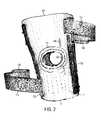
- FIG. 7is a perspective view of a patella stabilizer sleeve placed on a user's leg in accordance with an embodiment of the present invention.
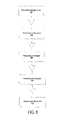
- FIG. 8is a flow diagram illustrating a method for using the patella stabilizer system in accordance with an embodiment of the present invention.
- the patella stabilizer system 100comprises a patella stabilizer sleeve 10 , an upper fastener assembly having a strap 112 , a lower fastener assembly having a strap 114 , and a patella support buttress 116 . While only two straps are shown in FIG. 1 , it will be understood to one of ordinary skill in the art that any number of straps may be used without departing from the spirit and scope of the present invention.
- the patella stabilizer sleeve 10is constructed using any natural or synthetic material, including both inelastic and elastic materials, having sufficient flexibility and resiliency to enable the patella stabilizer sleeve 10 to anatomically conform to the body member to which it is applied.
- the patella stabilizer sleeve 10may be formed of, for example, two-sided nylon Neoprene, which provides durability and elasticity.
- the two-sided nylon Neopreneallows the patella stabilizer sleeve 10 to be easily slipped onto a user leg and more particularly the knee area.
- the two-sided nylon Neoprenehas an approximate thickness between 1 ⁇ 8 to 3/16 inch.
- the outsidecomprising a front side 120 and a back side 122 , is constructed of UBL, which is standard and well known in the art.
- the body of straps 112 and 114with the exception of fasteners 124 and 126 may be constructed with hook a pile portions to facilitate adjustability and ease of use by user.
- the patella stabilizer sleeve 10includes a large patella opening 128 for added comfort, an open upper-end 102 , and an open lower-end 104 , and a popliteal opening 304 opposite the patella opening 128 (shown in FIG. 3 ).
- the upper fastener assembly and the lower fastener assembly having straps 112 , 114may be constructed with hook and pile portions to facilitate adjustability and ease of use by the user.
- an internal hinge 122is distinctly placed along a medial portion of the patella stabilizer sleeve 10 .
- the internal hinge 122may be either a polycentric (double axis) hinge, a single axis hinge, a complex hinge, or a spiral stay. Other types of hinges may also be used as will be shown in more detail below.
- a second hinge 132is disposed opposite hinge 122 , and is positioned on the outside portion of the knee to balance the support about the knee.
- Stitching 144is shown on the strap 112 as well as stitching 146 shown around the patella opening 128 . This stitching is shown for purposes of illustration only, and other stitching embodiments may be incorporated herein. All illustrations thereof should not be deemed limited in any respect relative to the principles of the present invention.
- the patella stabilizer system 100further includes a patella support buttress 116 .
- the buttress 116comprises a plurality of straps 134 and 136 .
- the body of straps 134 and 136with the exception of fasteners 138 and 140 may be constructed with hook and pile portions to facilitate adjustability.
- the buttress 116includes a front side 142 and a back side 144 (shown in FIG. 4B ).
- the front side 142is made of a material that has grip characteristics and prevents slippage when placed against human skin such as, for example, shark-skin.
- the back side 144 of the buttress 116may be constructed with hook and pile portions to facilitate adjustability and ease of use by the user.
- the buttress 116is adapted to be placed on an inside surface of the patella stabilizer sleeve 10 around a location on a circumferential edge of the patella opening 128 .
- the patella stabilizer sleeve 10includes four slots 148 , 150 , 152 , 154 (shown in FIG. 6 ) around the patella opening 128 .
- the slots 148 , 150 , 152 , 154( FIG. 6 ) are adapted to allow passage of the buttress straps 134 and 136 for securement of the buttress 116 to the patella stabilizer sleeve 10 .
- the inside surface of the patella stabilizer sleeve 10 around the circumferential edge of the patella opening 128may be constructed with hook and pile portions to engage the buttress 116 in order to facilitate adjustability of the buttress 116 .
- the buttress 116may be adjustably positioned on the inside surface of the patella stabilizer sleeve 10 around a location on the circumferential edge of the patella opening 128 to provide a desired pressure and properly align a user's patella.
- the buttress 116can be positioned in a medial or lateral direction relative to the user's patella.
- FIG. 2is a front view of an exemplary configuration of a patella stabilizer sleeve 10 in accordance with an embodiment of the present invention. Details of the patella stabilizer sleeve 10 have been disclosed with respect to FIG. 1 above.
- FIG. 3is a back view of an exemplary configuration of the patella stabilizer sleeve 10 in accordance with an embodiment of the present invention.
- the patella stabilizer sleeve 10further includes a popliteal opening 304 opposite the patella opening 128 for added comfort. It is important to note that FIGS. 1-3 and the description herein are directed to a universal patella stabilizer sleeve 10 adapted to properly align a user's patella and can be worn interchangeably on the left and the right knee of the user.
- FIGS. 4A-4Billustrate front and back views of a buttress 116 of the patella stabilizer system 100 in accordance with a preferred embodiment of the present invention.
- the buttress 116comprises a plurality of straps 134 , 136 .
- the body of straps 134 and 136with the exception of fasteners 138 and 140 may be constructed with hook and pile portions to facilitate adjustability and ease of use by the user.
- the buttress 116includes a front side 142 (illustrated in FIG. 4A ) and a back side 144 (illustrated in FIG. 4B ).
- the front side 142is made of a material that has grip characteristics and prevents slippage when placed against human skin such as, for example, shark-skin.
- the back side 144 of the buttress 116may be constructed with hook and pile portions to facilitate adjustability and ease of use by the user.
- the buttress 116is adapted to be placed on an inside surface of the patella stabilizer sleeve 10 around a location on a circumferential edge of the patella opening 128 .
- the buttress 116is horse-shoe like in shape.
- the buttress 116may be of other shapes such that the buttress 116 can be placed on an inside surface of the patella stabilizer sleeve 10 around a location on a circumferential edge of the patella opening 128 to provide a desired pressure and properly align the user's patella.
- FIGS. 5A-5Billustrate top and bottom views of the exemplary configuration of the patella stabilizer in accordance with an embodiment of the present invention.
- FIG. 6is an illustration of a close up view of a patella opening 128 of the patella stabilizer sleeve 10 in accordance with an embodiment of the present invention.
- the patella stabilizer sleeve 10includes a large patella opening 128 .
- the patella stabilizer sleeve 10further includes four slots 148 , 150 , 152 , 154 around the patella opening 128 .
- the slots 148 , 150 , 152 , 154are adapted to allow passage of the buttress straps 134 , 136 for securement of the buttress 116 to the patella stabilizer sleeve 10 .
- the inside surface of the patella stabilizer sleeve 10 around the circumferential edge of the patella opening 128may be constructed with hook and pile portions to engage and facilitate adjustability of the buttress 116 .
- the front side 142 of the buttress 116is made of a material that has grip characteristics and prevents slippage when placed against human skin such as, for example, shark-skin.
- the back side 144 of the buttress 116may be constructed with hook and pile portions to engage with the hook and pile portions on an inside surface of the patella stabilizer sleeve 10 around the circumferential edge of the patella opening 128 .
- the buttress 116is adapted to be placed on an inside surface of the patella stabilizer sleeve 10 around a location on a circumferential edge of the patella opening 128 .
- the buttress 116may be adjustably positioned on the inside surface of the patella stabilizer sleeve 10 around a location on the circumferential edge of the patella opening 128 to provide a desired pressure and properly align a user's patella.
- the buttress 116can be positioned in a medial or lateral direction relative to the user's patella.
- FIG. 7is a perspective view of a patella stabilizer sleeve 10 and the buttress 116 placed on a user's leg in accordance with an embodiment of the present invention.
- the patella stabilizer sleeve 10is adapted to be slipped onto the user's leg such that the lower strap 114 is adapted to secure a calf region 702 of the user while the upper strap 112 is adapted to secure a thigh region 704 of the user.
- FIG. 7further illustrates the slot 152 which allows passage of the buttress straps 136 for securement of the buttress 116 to the patella stabilizer sleeve 10 .
- the buttress 116is adapted to be placed on an inside surface of the patella stabilizer sleeve 10 around a location on a circumferential edge of the patella opening 128 .
- the buttress 116may be adjustably positioned on the inside surface of the patella stabilizer sleeve 10 around a location on the circumferential edge of the patella opening 128 to properly align a user's patella.
- the buttress 116can be positioned in a medial or lateral direction relative to the user's patella.
- the buttress 116which is adapted to be adjustably positioned on the inside surface of the patella stabilizer sleeve 10 around a location on the circumferential edge of the patella opening 128 , is adapted to properly align a user's patella.
- FIG. 8there is shown a flow diagram illustrating a method 800 for using the patella stabilizer sleeve 10 according to an embodiment of the present invention.
- the userslips the patella stabilizer sleeve 10 onto the user leg and more particularly the knee area through the open upper-end 102 of the patella stabilizer system 100 .
- the strap 112 of the upper fastener assemblyis secured about the thigh region of the user.
- the strap 114 of the lower fastener assemblyis secured about the calf region of the user.
- the buttress 116is adjustably positioned on the inside surface of the patella stabilizer sleeve 10 around a location on the circumferential edge of the patella opening 128 to provide a desired pressure and properly align a user's patella.
- the buttress 116can be positioned in a medial or lateral direction relative to the user's patella.
- the straps 112 , 114 , 134 , and 136are adjusted to a desired level by increasing or decreasing the tightness of the straps 112 , 114 , 134 , and 136 around the thigh region, the calf region and the patella region, respectively.
- hook and pile fastenersis a recognized structure to one skilled in the art and is often sold under the trademark Velcro®. It is well known that the hook and pile material engage one another. In addition, various surface designs, patterns, and colors may be used as well as various thicknesses of neoprene. Likewise, the present invention is not limited to the use of neoprene as other materials may prove satisfactory in their use as patella stabilizers.
- the size and shape of the patella stabilizer sleeve 10 along with the buttress 116 as shown hereinis an exemplary embodiment and other cutout shapes and clearance designs may be utilized in order to accommodate various leg sizes.
Landscapes
- Health & Medical Sciences (AREA)
- Nursing (AREA)
- Orthopedic Medicine & Surgery (AREA)
- Engineering & Computer Science (AREA)
- Biomedical Technology (AREA)
- Heart & Thoracic Surgery (AREA)
- Vascular Medicine (AREA)
- Life Sciences & Earth Sciences (AREA)
- Animal Behavior & Ethology (AREA)
- General Health & Medical Sciences (AREA)
- Public Health (AREA)
- Veterinary Medicine (AREA)
- Orthopedics, Nursing, And Contraception (AREA)
Abstract
Description
Claims (13)
Priority Applications (1)
| Application Number | Priority Date | Filing Date | Title |
|---|---|---|---|
| US12/037,320US7862528B2 (en) | 2007-02-28 | 2008-02-26 | Patella stabilizing method and system |
Applications Claiming Priority (2)
| Application Number | Priority Date | Filing Date | Title |
|---|---|---|---|
| US90444407P | 2007-02-28 | 2007-02-28 | |
| US12/037,320US7862528B2 (en) | 2007-02-28 | 2008-02-26 | Patella stabilizing method and system |
Publications (2)
| Publication Number | Publication Date |
|---|---|
| US20080300524A1 US20080300524A1 (en) | 2008-12-04 |
| US7862528B2true US7862528B2 (en) | 2011-01-04 |
Family
ID=40089064
Family Applications (1)
| Application Number | Title | Priority Date | Filing Date |
|---|---|---|---|
| US12/037,320Active - Reinstated2028-04-27US7862528B2 (en) | 2007-02-28 | 2008-02-26 | Patella stabilizing method and system |
Country Status (1)
| Country | Link |
|---|---|
| US (1) | US7862528B2 (en) |
Cited By (20)
| Publication number | Priority date | Publication date | Assignee | Title |
|---|---|---|---|---|
| USD635267S1 (en)* | 2010-07-23 | 2011-03-29 | Pang-Ching Chiang | Knee brace |
| USD654182S1 (en)* | 2011-06-16 | 2012-02-14 | Pang-Ching Chiang | Knee support |
| USD654181S1 (en)* | 2011-06-16 | 2012-02-14 | Pang-Ching Chiang | Knee support |
| USD683465S1 (en) | 2011-07-25 | 2013-05-28 | Ossur Hf | Patella buttress |
| USD683859S1 (en) | 2011-07-25 | 2013-06-04 | Ossur Hf | Knee brace |
| USD686330S1 (en)* | 2011-01-26 | 2013-07-16 | Bauerfeind Ag | Orthotic insert |
| USD687154S1 (en)* | 2012-05-03 | 2013-07-30 | Tsan-Jee Chen | Knee pad |
| USD710018S1 (en) | 2011-07-25 | 2014-07-29 | Ossur Hf | Knee brace |
| US9017274B2 (en) | 2010-12-22 | 2015-04-28 | Ossur Hf | Orthopedic device |
| US9113998B2 (en) | 2012-03-13 | 2015-08-25 | Ossur Hf | Patellofemoral device and method for using the same |
| US20170128248A1 (en)* | 2015-11-11 | 2017-05-11 | Gene Hur | Knee Pain Treatment Apparatus and Method of Use |
| CN104936559B (en)* | 2012-10-30 | 2017-08-08 | 吉博公司 | Knee cap keeps equipment and knee rectifier |
| WO2018013383A1 (en)* | 2016-07-13 | 2018-01-18 | Biosurgery Solutions Llc | Compressive brace for intraarticular needle procedures |
| US9931233B2 (en) | 2012-01-09 | 2018-04-03 | Breg, Inc. | Soft orthopedic knee brace for treatment of osteoarthritis |
| US10182935B2 (en) | 2014-10-01 | 2019-01-22 | Ossur Hf | Support for articles and methods for using the same |
| US10206804B1 (en)* | 2014-09-29 | 2019-02-19 | Weber Orthopedic, L.P. | Global osteoarthritis knee brace |
| US10420668B2 (en) | 2014-11-20 | 2019-09-24 | Ossur Iceland Ehf | Patella cup |
| US10932939B1 (en) | 2014-09-29 | 2021-03-02 | Weber Orthopedic, L.P. | Global osteoarthritis knee brace |
| USD916384S1 (en)* | 2019-05-31 | 2021-04-13 | Disk Dr. Co., Ltd. | Knee pad |
| US11497642B2 (en) | 2019-01-30 | 2022-11-15 | Ossur Iceland Ehf | Orthopedic device for patellofemoral issues |
Families Citing this family (10)
| Publication number | Priority date | Publication date | Assignee | Title |
|---|---|---|---|---|
| US8016779B2 (en) | 2007-04-09 | 2011-09-13 | Tyco Healthcare Group Lp | Compression device having cooling capability |
| US7959590B2 (en)* | 2007-04-19 | 2011-06-14 | New Options Sports | Method of and apparatus for patella support |
| US8114117B2 (en) | 2008-09-30 | 2012-02-14 | Tyco Healthcare Group Lp | Compression device with wear area |
| US8043242B2 (en)* | 2008-06-16 | 2011-10-25 | Thermotek, Inc. | Method of and system for joint therapy and stabilization |
| EP2442773B2 (en)* | 2009-06-16 | 2016-08-24 | Otto Bock HealthCare GmbH | Compression bandage |
| USD634851S1 (en)* | 2010-07-23 | 2011-03-22 | Pang-Ching Chiang | Knee brace |
| US10751221B2 (en)* | 2010-09-14 | 2020-08-25 | Kpr U.S., Llc | Compression sleeve with improved position retention |
| WO2014194313A1 (en)* | 2013-05-31 | 2014-12-04 | Mueller Sports Medicine, Inc. | Elbow brace |
| DE202015003437U1 (en)* | 2015-05-08 | 2015-06-15 | Thuasne Deutschland Gmbh | Orthosis for therapeutic treatment |
| US20250143906A1 (en)* | 2023-11-07 | 2025-05-08 | Jill C. POKASKI AZAR | Devices and methods to mitigate patella malpositioning |
Citations (16)
| Publication number | Priority date | Publication date | Assignee | Title |
|---|---|---|---|---|
| US4494534A (en) | 1983-03-07 | 1985-01-22 | Medical Designs, Inc. | Universal leg brace system |
| US4856501A (en) | 1987-06-29 | 1989-08-15 | Innovation Sports, Inc. | Knee brace having adjustable width frame pivoted to cuffs |
| US4873967A (en) | 1987-04-27 | 1989-10-17 | Sutherland Jeffrey L | Knee orthosis |
| US4986264A (en) | 1989-09-29 | 1991-01-22 | Miller Marion E | Knee brace |
| US5024216A (en)* | 1989-02-23 | 1991-06-18 | Tokyo Eizai Laboratory Co., Ltd. | Knee support |
| US5277697A (en)* | 1990-08-17 | 1994-01-11 | Hanger Orthopedic Group, Inc. | Patella-femoral brace |
| US5554104A (en) | 1992-12-18 | 1996-09-10 | Royce Medical Company | Custom formable knee brace |
| US5562605A (en) | 1994-08-10 | 1996-10-08 | Generation Ii Orthotics Inc. | Medial collateral ligament brace |
| US5624389A (en) | 1994-05-30 | 1997-04-29 | Otto Bock Orthopadische Industrie Besitz-und Verwaltungs-Kommanditgesells chaft | Knee joint orthosis |
| US5807298A (en)* | 1995-01-26 | 1998-09-15 | Dynorthotics Limited Partnership | Dynamic patella brace and method |
| US5810752A (en) | 1992-04-29 | 1998-09-22 | Otto Bock Orthopaedische Industrie Besitz- Und Verwaltungs Kg | Knee joint orthosis |
| US5873848A (en)* | 1996-06-14 | 1999-02-23 | Depuy, Inc. | Orthopedic brace |
| US5921946A (en) | 1997-10-22 | 1999-07-13 | Smith & Nephew, Inc. | Joint brace hinges |
| US6066110A (en) | 1998-10-23 | 2000-05-23 | Nauert; Richard S. | User customizable knee brace |
| US6287269B1 (en)* | 1998-04-20 | 2001-09-11 | Leonardo Osti | Dynamic orthesis device for the conservative treatment of patellofemoral instability of the knee |
| US7060045B2 (en)* | 2000-09-22 | 2006-06-13 | Breg, Inc. | Orthosis providing dynamic tracking of the patello-femoral joint |
- 2008
- 2008-02-26USUS12/037,320patent/US7862528B2/enactiveActive - Reinstated
Patent Citations (16)
| Publication number | Priority date | Publication date | Assignee | Title |
|---|---|---|---|---|
| US4494534A (en) | 1983-03-07 | 1985-01-22 | Medical Designs, Inc. | Universal leg brace system |
| US4873967A (en) | 1987-04-27 | 1989-10-17 | Sutherland Jeffrey L | Knee orthosis |
| US4856501A (en) | 1987-06-29 | 1989-08-15 | Innovation Sports, Inc. | Knee brace having adjustable width frame pivoted to cuffs |
| US5024216A (en)* | 1989-02-23 | 1991-06-18 | Tokyo Eizai Laboratory Co., Ltd. | Knee support |
| US4986264A (en) | 1989-09-29 | 1991-01-22 | Miller Marion E | Knee brace |
| US5277697A (en)* | 1990-08-17 | 1994-01-11 | Hanger Orthopedic Group, Inc. | Patella-femoral brace |
| US5810752A (en) | 1992-04-29 | 1998-09-22 | Otto Bock Orthopaedische Industrie Besitz- Und Verwaltungs Kg | Knee joint orthosis |
| US5554104A (en) | 1992-12-18 | 1996-09-10 | Royce Medical Company | Custom formable knee brace |
| US5624389A (en) | 1994-05-30 | 1997-04-29 | Otto Bock Orthopadische Industrie Besitz-und Verwaltungs-Kommanditgesells chaft | Knee joint orthosis |
| US5562605A (en) | 1994-08-10 | 1996-10-08 | Generation Ii Orthotics Inc. | Medial collateral ligament brace |
| US5807298A (en)* | 1995-01-26 | 1998-09-15 | Dynorthotics Limited Partnership | Dynamic patella brace and method |
| US5873848A (en)* | 1996-06-14 | 1999-02-23 | Depuy, Inc. | Orthopedic brace |
| US5921946A (en) | 1997-10-22 | 1999-07-13 | Smith & Nephew, Inc. | Joint brace hinges |
| US6287269B1 (en)* | 1998-04-20 | 2001-09-11 | Leonardo Osti | Dynamic orthesis device for the conservative treatment of patellofemoral instability of the knee |
| US6066110A (en) | 1998-10-23 | 2000-05-23 | Nauert; Richard S. | User customizable knee brace |
| US7060045B2 (en)* | 2000-09-22 | 2006-06-13 | Breg, Inc. | Orthosis providing dynamic tracking of the patello-femoral joint |
Cited By (31)
| Publication number | Priority date | Publication date | Assignee | Title |
|---|---|---|---|---|
| USD635267S1 (en)* | 2010-07-23 | 2011-03-29 | Pang-Ching Chiang | Knee brace |
| US11298255B2 (en) | 2010-12-22 | 2022-04-12 | Ossur Hf | Orthopedic device |
| US10231860B2 (en) | 2010-12-22 | 2019-03-19 | Ossur Hf | Orthopedic device |
| US9017274B2 (en) | 2010-12-22 | 2015-04-28 | Ossur Hf | Orthopedic device |
| USD686330S1 (en)* | 2011-01-26 | 2013-07-16 | Bauerfeind Ag | Orthotic insert |
| USD654182S1 (en)* | 2011-06-16 | 2012-02-14 | Pang-Ching Chiang | Knee support |
| USD654181S1 (en)* | 2011-06-16 | 2012-02-14 | Pang-Ching Chiang | Knee support |
| USD710018S1 (en) | 2011-07-25 | 2014-07-29 | Ossur Hf | Knee brace |
| USD810309S1 (en) | 2011-07-25 | 2018-02-13 | Ossur Hf | Knee brace |
| USD716954S1 (en) | 2011-07-25 | 2014-11-04 | Ossur Hf | Knee brace |
| USD683465S1 (en) | 2011-07-25 | 2013-05-28 | Ossur Hf | Patella buttress |
| USD683859S1 (en) | 2011-07-25 | 2013-06-04 | Ossur Hf | Knee brace |
| USD758598S1 (en) | 2011-07-25 | 2016-06-07 | Ossur Hf | Knee brace |
| USD716955S1 (en) | 2011-07-25 | 2014-11-04 | Ossur Hf | Knee brace |
| US9931233B2 (en) | 2012-01-09 | 2018-04-03 | Breg, Inc. | Soft orthopedic knee brace for treatment of osteoarthritis |
| US9532895B2 (en) | 2012-03-13 | 2017-01-03 | Ossur Hf | Patellofemoral device and method for using the same |
| US9113998B2 (en) | 2012-03-13 | 2015-08-25 | Ossur Hf | Patellofemoral device and method for using the same |
| USD687154S1 (en)* | 2012-05-03 | 2013-07-30 | Tsan-Jee Chen | Knee pad |
| CN104936559B (en)* | 2012-10-30 | 2017-08-08 | 吉博公司 | Knee cap keeps equipment and knee rectifier |
| US10932939B1 (en) | 2014-09-29 | 2021-03-02 | Weber Orthopedic, L.P. | Global osteoarthritis knee brace |
| US10206804B1 (en)* | 2014-09-29 | 2019-02-19 | Weber Orthopedic, L.P. | Global osteoarthritis knee brace |
| US12251327B2 (en) | 2014-10-01 | 2025-03-18 | Ossur Hr | Support for articles and methods for using the same |
| US10182935B2 (en) | 2014-10-01 | 2019-01-22 | Ossur Hf | Support for articles and methods for using the same |
| US11304838B2 (en) | 2014-10-01 | 2022-04-19 | Ossur Hf | Support for articles and methods for using the same |
| US10420668B2 (en) | 2014-11-20 | 2019-09-24 | Ossur Iceland Ehf | Patella cup |
| US10709593B2 (en)* | 2015-11-11 | 2020-07-14 | Gene Hur | Knee pain treatment apparatus and method of use |
| US20170128248A1 (en)* | 2015-11-11 | 2017-05-11 | Gene Hur | Knee Pain Treatment Apparatus and Method of Use |
| WO2018013383A1 (en)* | 2016-07-13 | 2018-01-18 | Biosurgery Solutions Llc | Compressive brace for intraarticular needle procedures |
| US11497642B2 (en) | 2019-01-30 | 2022-11-15 | Ossur Iceland Ehf | Orthopedic device for patellofemoral issues |
| US12109139B2 (en) | 2019-01-30 | 2024-10-08 | Ossur Iceland Ehf | Orthopedic device for patellofemoral issues |
| USD916384S1 (en)* | 2019-05-31 | 2021-04-13 | Disk Dr. Co., Ltd. | Knee pad |
Also Published As
| Publication number | Publication date |
|---|---|
| US20080300524A1 (en) | 2008-12-04 |
Similar Documents
| Publication | Publication Date | Title |
|---|---|---|
| US7862528B2 (en) | Patella stabilizing method and system | |
| US7959590B2 (en) | Method of and apparatus for patella support | |
| US8043242B2 (en) | Method of and system for joint therapy and stabilization | |
| US7217249B2 (en) | Adjustable hinge joint support | |
| US10052221B2 (en) | Orthopedic device for treating osteoarthritis of the knee | |
| US6190344B1 (en) | Orthopaedic support fastening system | |
| US8308669B2 (en) | Knee orthosis with hinged shin and thigh cuff | |
| USRE37297E1 (en) | Dynamic orthopedic knee brace assembly | |
| US8376976B2 (en) | Method of and apparatus for wrist stabilization | |
| US4905678A (en) | Hip stabilizer | |
| US7862529B2 (en) | Neuromusculoskeletal knee support device | |
| US5658241A (en) | Multi-functional dynamic splint | |
| US20030204156A1 (en) | Knee brace with patella stabilizer | |
| US8007454B1 (en) | Ankle support assembly and method of supporting an ankle | |
| US10085869B2 (en) | Knee orthosis for treatment of PCL injury | |
| US20120220910A1 (en) | Knee support device having adjustable openings at opposing ends | |
| US9089403B2 (en) | Knee orthosis with hinged shin and thigh cuffs | |
| US8187212B2 (en) | Pain-alleviating orthopaedic appliance | |
| US9265646B2 (en) | Orthotic device for treating knee flexion contracture | |
| EP2941226A2 (en) | Orthopedic device and method for securing the same | |
| WO2008144078A1 (en) | Neurological motor therapy suit | |
| CN108135720A (en) | Customizable knee brace designed for osteoarthritis patients | |
| US8690811B2 (en) | Knee brace | |
| US20190254851A1 (en) | Elbow Orthosis | |
| US20240358536A1 (en) | Knee support brace and method of wearing same |
Legal Events
| Date | Code | Title | Description |
|---|---|---|---|
| AS | Assignment | Owner name:NEW OPTIONS SPORTS, TEXAS Free format text:ASSIGNMENT OF ASSIGNORS INTEREST;ASSIGNOR:SCOTT, JOHN;REEL/FRAME:021416/0518 Effective date:20080725 | |
| STCF | Information on status: patent grant | Free format text:PATENTED CASE | |
| REMI | Maintenance fee reminder mailed | ||
| FPAY | Fee payment | Year of fee payment:4 | |
| SULP | Surcharge for late payment | ||
| MAFP | Maintenance fee payment | Free format text:PAYMENT OF MAINTENANCE FEE, 8TH YR, SMALL ENTITY (ORIGINAL EVENT CODE: M2552) Year of fee payment:8 | |
| FEPP | Fee payment procedure | Free format text:MAINTENANCE FEE REMINDER MAILED (ORIGINAL EVENT CODE: REM.); ENTITY STATUS OF PATENT OWNER: SMALL ENTITY | |
| PRDP | Patent reinstated due to the acceptance of a late maintenance fee | Effective date:20230123 | |
| FEPP | Fee payment procedure | Free format text:PETITION RELATED TO MAINTENANCE FEES FILED (ORIGINAL EVENT CODE: PMFP); ENTITY STATUS OF PATENT OWNER: SMALL ENTITY Free format text:PETITION RELATED TO MAINTENANCE FEES GRANTED (ORIGINAL EVENT CODE: PMFG); ENTITY STATUS OF PATENT OWNER: SMALL ENTITY Free format text:SURCHARGE, PETITION TO ACCEPT PYMT AFTER EXP, UNINTENTIONAL. (ORIGINAL EVENT CODE: M2558); ENTITY STATUS OF PATENT OWNER: SMALL ENTITY | |
| MAFP | Maintenance fee payment | Free format text:PAYMENT OF MAINTENANCE FEE, 12TH YR, SMALL ENTITY (ORIGINAL EVENT CODE: M2553); ENTITY STATUS OF PATENT OWNER: SMALL ENTITY Year of fee payment:12 | |
| AS | Assignment | Owner name:CAERUS CORP., MINNESOTA Free format text:ASSIGNMENT OF ASSIGNORS INTEREST;ASSIGNOR:NEW OPTIONS SPORTS;REEL/FRAME:062637/0841 Effective date:20230208 |