US7862519B1 - Easy-to-use multi-use body fluid specimen collection and analyte sensing assembly - Google Patents
Easy-to-use multi-use body fluid specimen collection and analyte sensing assemblyDownload PDFInfo
- Publication number
- US7862519B1 US7862519B1US10/463,848US46384803AUS7862519B1US 7862519 B1US7862519 B1US 7862519B1US 46384803 AUS46384803 AUS 46384803AUS 7862519 B1US7862519 B1US 7862519B1
- Authority
- US
- United States
- Prior art keywords
- assembly
- measurement
- membrane
- electrical conductor
- sensing
- Prior art date
- Legal status (The legal status is an assumption and is not a legal conclusion. Google has not performed a legal analysis and makes no representation as to the accuracy of the status listed.)
- Expired - Fee Related, expires
Links
Images


Classifications
- A—HUMAN NECESSITIES
- A61—MEDICAL OR VETERINARY SCIENCE; HYGIENE
- A61B—DIAGNOSIS; SURGERY; IDENTIFICATION
- A61B5/00—Measuring for diagnostic purposes; Identification of persons
- A61B5/145—Measuring characteristics of blood in vivo, e.g. gas concentration or pH-value ; Measuring characteristics of body fluids or tissues, e.g. interstitial fluid or cerebral tissue
- A61B5/14532—Measuring characteristics of blood in vivo, e.g. gas concentration or pH-value ; Measuring characteristics of body fluids or tissues, e.g. interstitial fluid or cerebral tissue for measuring glucose, e.g. by tissue impedance measurement
- A—HUMAN NECESSITIES
- A61—MEDICAL OR VETERINARY SCIENCE; HYGIENE
- A61B—DIAGNOSIS; SURGERY; IDENTIFICATION
- A61B5/00—Measuring for diagnostic purposes; Identification of persons
- A61B5/15—Devices for taking samples of blood
- A61B5/150007—Details
- A61B5/150015—Source of blood
- A61B5/150022—Source of blood for capillary blood or interstitial fluid
- A—HUMAN NECESSITIES
- A61—MEDICAL OR VETERINARY SCIENCE; HYGIENE
- A61B—DIAGNOSIS; SURGERY; IDENTIFICATION
- A61B5/00—Measuring for diagnostic purposes; Identification of persons
- A61B5/15—Devices for taking samples of blood
- A61B5/150007—Details
- A61B5/150358—Strips for collecting blood, e.g. absorbent
- A—HUMAN NECESSITIES
- A61—MEDICAL OR VETERINARY SCIENCE; HYGIENE
- A61B—DIAGNOSIS; SURGERY; IDENTIFICATION
- A61B5/00—Measuring for diagnostic purposes; Identification of persons
- A61B5/15—Devices for taking samples of blood
- A61B5/150007—Details
- A61B5/150374—Details of piercing elements or protective means for preventing accidental injuries by such piercing elements
- A61B5/150381—Design of piercing elements
- A61B5/150412—Pointed piercing elements, e.g. needles, lancets for piercing the skin
- A61B5/150435—Specific design of proximal end
- A—HUMAN NECESSITIES
- A61—MEDICAL OR VETERINARY SCIENCE; HYGIENE
- A61B—DIAGNOSIS; SURGERY; IDENTIFICATION
- A61B5/00—Measuring for diagnostic purposes; Identification of persons
- A61B5/15—Devices for taking samples of blood
- A61B5/150007—Details
- A61B5/150374—Details of piercing elements or protective means for preventing accidental injuries by such piercing elements
- A61B5/150381—Design of piercing elements
- A61B5/150503—Single-ended needles
- A—HUMAN NECESSITIES
- A61—MEDICAL OR VETERINARY SCIENCE; HYGIENE
- A61B—DIAGNOSIS; SURGERY; IDENTIFICATION
- A61B5/00—Measuring for diagnostic purposes; Identification of persons
- A61B5/15—Devices for taking samples of blood
- A61B5/151—Devices specially adapted for taking samples of capillary blood, e.g. by lancets, needles or blades
- A61B5/15101—Details
- A61B5/15103—Piercing procedure
- A61B5/15105—Purely manual piercing, i.e. the user pierces the skin without the assistance of any driving means or driving devices
- A—HUMAN NECESSITIES
- A61—MEDICAL OR VETERINARY SCIENCE; HYGIENE
- A61B—DIAGNOSIS; SURGERY; IDENTIFICATION
- A61B5/00—Measuring for diagnostic purposes; Identification of persons
- A61B5/15—Devices for taking samples of blood
- A61B5/151—Devices specially adapted for taking samples of capillary blood, e.g. by lancets, needles or blades
- A61B5/15146—Devices loaded with multiple lancets simultaneously, e.g. for serial firing without reloading, for example by use of stocking means.
- A61B5/15148—Constructional features of stocking means, e.g. strip, roll, disc, cartridge, belt or tube
- A61B5/15149—Arrangement of piercing elements relative to each other
- A61B5/15151—Each piercing element being stocked in a separate isolated compartment
- A—HUMAN NECESSITIES
- A61—MEDICAL OR VETERINARY SCIENCE; HYGIENE
- A61B—DIAGNOSIS; SURGERY; IDENTIFICATION
- A61B5/00—Measuring for diagnostic purposes; Identification of persons
- A61B5/15—Devices for taking samples of blood
- A61B5/151—Devices specially adapted for taking samples of capillary blood, e.g. by lancets, needles or blades
- A61B5/15146—Devices loaded with multiple lancets simultaneously, e.g. for serial firing without reloading, for example by use of stocking means.
- A61B5/15148—Constructional features of stocking means, e.g. strip, roll, disc, cartridge, belt or tube
- A61B5/15157—Geometry of stocking means or arrangement of piercing elements therein
- A61B5/15159—Piercing elements stocked in or on a disc
- A61B5/15161—Characterized by propelling the piercing element in a radial direction relative to the disc
- A—HUMAN NECESSITIES
- A61—MEDICAL OR VETERINARY SCIENCE; HYGIENE
- A61B—DIAGNOSIS; SURGERY; IDENTIFICATION
- A61B5/00—Measuring for diagnostic purposes; Identification of persons
- A61B5/15—Devices for taking samples of blood
- A61B5/157—Devices characterised by integrated means for measuring characteristics of blood
Definitions
- a coated wire assemblyuses a wire having an electrochemically active metal (typically platinum) that is largely coated with insulation. A portion of this insulation is removed to form an electrode that is then covered with a assembly of membranes that produces an electric current when the analyte of interest (typically glucose) is present.
- analyte of interesttypically glucose
- a coated wire assemblyit has been found that a problem is created in the removal of the wire insulation. With respect to insulated wires it has been found that the insulation is generally not applied in a truly concentric manner. Accordingly, if a laser beam is used to remove the insulation it tends to pit and stipple the electrochemically active surface of the wire, increasing its surface area. Although a large surface area is typically desirable, the process is unpredictable because of the unevenness of the insulation coat. As a result a non-uniformity is introduced into each set of sensing elements.
- the present inventionis a multiple use analyte sensing assembly that includes a long, thin conductor.
- a plurality of sensing sitesare spaced along the conductor and each sensing site includes a membrane system adapted to create a current when placed into contact with body fluid containing the analyte.
- the assemblyalso includes a housing, having a housing aperture and an uptake spool and a payout spool, located within the housing, the sensing sites being wrapped about the payout spool before the sensing assembly is used.
- a sensor positioning actuatorfor turning the uptake spool so that each sensing site is moved, in sequence, to the housing aperture and then to the uptake spool.
- the assemblyalso includes a skin broaching assembly, having a multiple lancet holding mechanism, a multiplicity of lancets held by the multiple lancet holding mechanism and a lancet positioning actuator adapted to move, in sequence, each lancet to a position coincident to the aperture.
- a lancet use actuatoris adapted to move a lancet that is positioned coincident to the aperture, at least partially through the aperture and then back again.
- FIG. 1is a side view of a cassette style multiple use analyte sensing assembly according to the present invention.
- FIG. 2is a side sectional view of the cassette style multiple use analyte sensing assembly of FIG. 1 .
- FIG. 3Ais a detail section view of the cassette style multiple use analyte sensing assembly of FIG. 1 .
- FIG. 3Bis a detail section view of the cassette style multiple use analyte sensing assembly of FIG. 1 showing the lancet in its protruding state.
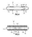
- FIG. 4is a greatly enlarged side view of the sense wire that is part of the present invention.
- FIG. 5is a greatly enlarged side view of an alternative embodiment of a sense wire that is part of the present invention.
- a blood analyte measurement assembly 10in a first preferred embodiment, includes a cartridge 12 housing a pay-out spool 14 and an uptake spool 15 of a membrane system coated wire assembly 16 bearing a number of sensing sites 18 ( FIGS. 4 and 5 ).
- a set of guide rollers 17maintain coated wire assembly 16 in proper tension as it is moved.
- a sensor positioning actuator 19turns uptake spool 15 , so that each sensing site 18 is in turn moved to be coincident with an aperture 20 .
- sensor positioning assembly 19includes an electric motor and a battery.
- each sensing site 18 of assembly 16is a location in which a layer of insulation 114 has been stripped off of a central conductor 112 , which may be circular in cross section. Additionally, the central conductor 112 is coated with a membrane system that includes three membranes 124 , 126 and 128 adapted to produce an electrical current, when exposed to an analyte bearing fluid, provided that a voltage is present on wire 112 , relative to a nearby reference electrode (discussed further below).
- a membrane systemthat includes three membranes 124 , 126 and 128 adapted to produce an electrical current, when exposed to an analyte bearing fluid, provided that a voltage is present on wire 112 , relative to a nearby reference electrode (discussed further below).
- a membrane assemblyis described in U.S. Pat. No. 5,165,407, issued Nov. 24, 1992.
- Another such membrane assemblyis described in application Ser. No. 10/342,144 filed Jan. 13, 2003, which is assigned to the same assignee as the present application and
- membrane 124is an interferent excluding layer made of a material such as sulphonated poly-ether sulphone or 3-amino phenol.
- Membrane 126is made of an enzyme that reacts with glucose, such as glucose oxidase.
- Membrane 128is a permselective layer for ensuring an adequate concentration of oxygen, relative to the concentration of glucose.
- Membrane 128may be a copolymer of the type described in U.S. Pat. No. 5,428,123.
- all of central conductor 112 of an alternative coated wire assembly 16 ′is coated with an analyte reactive membrane system 124 , 126 , and 128 , which may be identical to layers 124 , 126 and 128 in the system of FIG. 4 except for that the system of FIG. 5 is applied continuously by way of a sequence of three baths through which conductor 112 is drawn.
- Layer 128is, in turn, coated with an absorbent layer 120 , such as cellulose.
- Layer 120controls the amount of blood that comes into contact with membrane layer 128 so that an exact known volume of blood is analyzed.
- the volume of bloodmay be set at a level of between 50 nanoliters and 200 nanoliters of body fluid.
- a first sensing site 18is separated from a second sensing site 18 by means of a constrictive band 130 , which prevents the flow of blood between the two sites 18 .
- a reference electrodeis integrated into assembly 16 ′ in the form of a grounded conductive strip 140 extending along one side of assembly 16 ′.
- a single layer of a mediated enzymeis used for the detection of glucose.
- layers 124 , 126 , and 128are all the same and are composed of a mediated enzyme such as dimethyl ferrocene.
- a mediated enzymesuch as dimethyl ferrocene.
- the use of this mediated enzyme for detecting analytesis described in U.S. Pat. No. 4,545,382 and will be familiar to skilled persons. In this instance, however, this enzyme is applied directly to a conductive wire, circular in cross section, for directly sensing glucose.
- wire 112may be a drawn filled tube of an electrochemically active metal, such as platinum, filled with a structurally robust material such as tantalum.
- wire 112is made of a structurally robust material, such as tantalum, plated or otherwise coated, by means such as vapor deposition, with an electrochemically active metal such as platinum.
- Other materials that may be used for the structurally robust materialinclude stainless steel and nitinol (an alloy of titanium and nickel).
- the electroactive materialmay be gold.
- Wire 112may have a diameter of between 10 and 300 microns.
- One problem encountered in the type of technology discussed hereis that of achieving a set, exactly repeated volume of enzyme in layer 126 .
- One method for addressing this problemis to use an ink-jet nozzle to apply layer 126 onto the underlying surface.
- cartridge or housing 12contains a multiple lancet holding mechanism 30 in the form of a wheel bearing a multiplicity of lancet assemblies 34 each containing a lancet 32 and defining a blood receiving cavity 38 ( FIG. 3A ).
- Each lancet assembly 34includes an aperture 25 that cooperates with a notch 26 in housing 12 , so that a sensing site 18 can be wetted with blood during test.
- a knob 22is used to advance mechanism 30 before each blood glucose measurement so that a fresh lancet assembly 34 is positioned above aperture 20 , coincident with a sensing site 18 on the coated wire 16 .
- a button 28( FIG. 1 ) on housing 12 causing the sensor positioning actuator 19 to move a fresh measurement site into alignment with the housing aperture 20 ( FIG. 2 ).
- the useralso turns a knob 22 to move a fresh lancet assembly to be coincident with aperture 20 .
- the cartridge 12is pressed against the skin 36 at aperture 20 and a manual actuator 40 is used by the patient to press lancet 34 through skin 36 , causing blood 37 to flow into cavity 38 .
- a voltage application and current sensing block 21( FIG. 1 ) places a voltage onto conductor 112 ( FIG. 4 ) and the flow of current through conductor 112 is measured, indicating the glucose level in the blood 37 .
- strip 140is the reference electrode. Otherwise lancet 32 or skin 36 serves as a reference. After cavity 38 is sufficiently filled with blood 37 , the patient may pull upwardly on actuator 40 , thereby permitting spring 42 to pull lancet 34 back into assembly 32 .
- sensing site 18is moved away from aperture 20 by action of actuator 19 .
- aperture 20is closed between sensing operations by a sliding closure 50 , to prevent contamination of media 16 .
- this assembly 10bears the relationship to currently available glucose testing system as a cartridge film camera, or disposable camera, bears to the type of camera in which the film had to be loaded frame by frame.
- the patientsimply presses a button, pushes in the lancet and waits a short while for the result.
- the step of disposing of a paper striphas been eliminated. Because the tubular housing receives a volume of blood that is on the order of a micro liter, which quickly dries, there appears to be no problem of blood disposal.
- the step of producing individual sensing elementshas been eliminated, it appears that the cost of each sensing site can be reduced to a fraction of a penny.
Landscapes
- Health & Medical Sciences (AREA)
- Life Sciences & Earth Sciences (AREA)
- Physics & Mathematics (AREA)
- Molecular Biology (AREA)
- Animal Behavior & Ethology (AREA)
- Pathology (AREA)
- Engineering & Computer Science (AREA)
- Biomedical Technology (AREA)
- Heart & Thoracic Surgery (AREA)
- Medical Informatics (AREA)
- Veterinary Medicine (AREA)
- Surgery (AREA)
- Biophysics (AREA)
- General Health & Medical Sciences (AREA)
- Public Health (AREA)
- Hematology (AREA)
- Dermatology (AREA)
- Emergency Medicine (AREA)
- Optics & Photonics (AREA)
- Geometry (AREA)
- Measurement Of The Respiration, Hearing Ability, Form, And Blood Characteristics Of Living Organisms (AREA)
Abstract
Description
Claims (33)
Priority Applications (1)
| Application Number | Priority Date | Filing Date | Title |
|---|---|---|---|
| US10/463,848US7862519B1 (en) | 2003-05-21 | 2003-06-16 | Easy-to-use multi-use body fluid specimen collection and analyte sensing assembly |
Applications Claiming Priority (3)
| Application Number | Priority Date | Filing Date | Title |
|---|---|---|---|
| US47301303P | 2003-05-21 | 2003-05-21 | |
| US47301403P | 2003-05-21 | 2003-05-21 | |
| US10/463,848US7862519B1 (en) | 2003-05-21 | 2003-06-16 | Easy-to-use multi-use body fluid specimen collection and analyte sensing assembly |
Publications (1)
| Publication Number | Publication Date |
|---|---|
| US7862519B1true US7862519B1 (en) | 2011-01-04 |
Family
ID=43384921
Family Applications (1)
| Application Number | Title | Priority Date | Filing Date |
|---|---|---|---|
| US10/463,848Expired - Fee RelatedUS7862519B1 (en) | 2003-05-21 | 2003-06-16 | Easy-to-use multi-use body fluid specimen collection and analyte sensing assembly |
Country Status (1)
| Country | Link |
|---|---|
| US (1) | US7862519B1 (en) |
Cited By (3)
| Publication number | Priority date | Publication date | Assignee | Title |
|---|---|---|---|---|
| US20100094325A1 (en)* | 2007-05-16 | 2010-04-15 | Ahmet Konya | Pricking system |
| US20110144463A1 (en)* | 2008-02-27 | 2011-06-16 | Benny Pesach | Device, system and method for modular analyte monitoring |
| US20140052025A1 (en)* | 2004-04-30 | 2014-02-20 | Roche Diagnostics Operations, Inc. | Lancets for bodily fluid sampling supplied on a tape |
Citations (23)
| Publication number | Priority date | Publication date | Assignee | Title |
|---|---|---|---|---|
| US4953552A (en) | 1989-04-21 | 1990-09-04 | Demarzo Arthur P | Blood glucose monitoring system |
| US5165407A (en) | 1990-04-19 | 1992-11-24 | The University Of Kansas | Implantable glucose sensor |
| US5428123A (en) | 1992-04-24 | 1995-06-27 | The Polymer Technology Group | Copolymers and non-porous, semi-permeable membrane thereof and its use for permeating molecules of predetermined molecular weight range |
| US5510266A (en) | 1995-05-05 | 1996-04-23 | Bayer Corporation | Method and apparatus of handling multiple sensors in a glucose monitoring instrument system |
| US5660163A (en) | 1993-11-19 | 1997-08-26 | Alfred E. Mann Foundation For Scientific Research | Glucose sensor assembly |
| US5820622A (en)* | 1994-11-04 | 1998-10-13 | Elan Medical Technologies Limited | Analyte-controlled liquid delivery device and analyte monitor |
| US5871494A (en) | 1997-12-04 | 1999-02-16 | Hewlett-Packard Company | Reproducible lancing for sampling blood |
| US6051392A (en) | 1998-06-10 | 2000-04-18 | Matsushita Electric Industrial Co., Ltd. | Method for quantitating a substrate and measurement device used therefor |
| US6228100B1 (en)* | 1999-10-25 | 2001-05-08 | Steven Schraga | Multi-use lancet device |
| WO2001064105A1 (en) | 2000-03-02 | 2001-09-07 | Inverness Medical Technology, Inc. | Combined lancet and electrochemical analyte-testing apparatus |
| WO2001073124A2 (en) | 2000-03-28 | 2001-10-04 | Diabetes Diagnostics, Inc. | Rapid response glucose sensor |
| US6309351B1 (en) | 1995-12-28 | 2001-10-30 | Cygnus, Inc. | Methods for monitoring a physiological analyte |
| US6329161B1 (en)* | 1993-12-02 | 2001-12-11 | Therasense, Inc. | Subcutaneous glucose electrode |
| US6352514B1 (en) | 1996-05-17 | 2002-03-05 | Amira Medical | Methods and apparatus for sampling and analyzing body fluid |
| US6391643B1 (en)* | 1998-10-28 | 2002-05-21 | Cygnus, Inc. | Kit and method for quality control testing of an iontophoretic sampling system |
| US6477395B2 (en) | 1997-10-20 | 2002-11-05 | Medtronic Minimed, Inc. | Implantable enzyme-based monitoring systems having improved longevity due to improved exterior surfaces |
| US20020169394A1 (en)* | 1993-11-15 | 2002-11-14 | Eppstein Jonathan A. | Integrated tissue poration, fluid harvesting and analysis device, and method therefor |
| US6484046B1 (en) | 1998-03-04 | 2002-11-19 | Therasense, Inc. | Electrochemical analyte sensor |
| US20030032892A1 (en)* | 2001-04-25 | 2003-02-13 | Erlach Julian Van | Nanodevices, microdevices and sensors on in-vivo structures and method for the same |
| US6534017B1 (en) | 1997-04-11 | 2003-03-18 | Roche Diagnostics Gmbh | Test element storage device |
| US6592745B1 (en) | 1998-10-08 | 2003-07-15 | Therasense, Inc. | Method of using a small volume in vitro analyte sensor with diffusible or non-leachable redox mediator |
| US20040064068A1 (en)* | 2002-09-30 | 2004-04-01 | Denuzzio John D. | Integrated lancet and bodily fluid sensor |
| US6988996B2 (en)* | 2001-06-08 | 2006-01-24 | Roche Diagnostics Operatons, Inc. | Test media cassette for bodily fluid testing device |
- 2003
- 2003-06-16USUS10/463,848patent/US7862519B1/ennot_activeExpired - Fee Related
Patent Citations (23)
| Publication number | Priority date | Publication date | Assignee | Title |
|---|---|---|---|---|
| US4953552A (en) | 1989-04-21 | 1990-09-04 | Demarzo Arthur P | Blood glucose monitoring system |
| US5165407A (en) | 1990-04-19 | 1992-11-24 | The University Of Kansas | Implantable glucose sensor |
| US5428123A (en) | 1992-04-24 | 1995-06-27 | The Polymer Technology Group | Copolymers and non-porous, semi-permeable membrane thereof and its use for permeating molecules of predetermined molecular weight range |
| US20020169394A1 (en)* | 1993-11-15 | 2002-11-14 | Eppstein Jonathan A. | Integrated tissue poration, fluid harvesting and analysis device, and method therefor |
| US5660163A (en) | 1993-11-19 | 1997-08-26 | Alfred E. Mann Foundation For Scientific Research | Glucose sensor assembly |
| US6329161B1 (en)* | 1993-12-02 | 2001-12-11 | Therasense, Inc. | Subcutaneous glucose electrode |
| US5820622A (en)* | 1994-11-04 | 1998-10-13 | Elan Medical Technologies Limited | Analyte-controlled liquid delivery device and analyte monitor |
| US5510266A (en) | 1995-05-05 | 1996-04-23 | Bayer Corporation | Method and apparatus of handling multiple sensors in a glucose monitoring instrument system |
| US6309351B1 (en) | 1995-12-28 | 2001-10-30 | Cygnus, Inc. | Methods for monitoring a physiological analyte |
| US6352514B1 (en) | 1996-05-17 | 2002-03-05 | Amira Medical | Methods and apparatus for sampling and analyzing body fluid |
| US6534017B1 (en) | 1997-04-11 | 2003-03-18 | Roche Diagnostics Gmbh | Test element storage device |
| US6477395B2 (en) | 1997-10-20 | 2002-11-05 | Medtronic Minimed, Inc. | Implantable enzyme-based monitoring systems having improved longevity due to improved exterior surfaces |
| US5871494A (en) | 1997-12-04 | 1999-02-16 | Hewlett-Packard Company | Reproducible lancing for sampling blood |
| US6484046B1 (en) | 1998-03-04 | 2002-11-19 | Therasense, Inc. | Electrochemical analyte sensor |
| US6051392A (en) | 1998-06-10 | 2000-04-18 | Matsushita Electric Industrial Co., Ltd. | Method for quantitating a substrate and measurement device used therefor |
| US6592745B1 (en) | 1998-10-08 | 2003-07-15 | Therasense, Inc. | Method of using a small volume in vitro analyte sensor with diffusible or non-leachable redox mediator |
| US6391643B1 (en)* | 1998-10-28 | 2002-05-21 | Cygnus, Inc. | Kit and method for quality control testing of an iontophoretic sampling system |
| US6228100B1 (en)* | 1999-10-25 | 2001-05-08 | Steven Schraga | Multi-use lancet device |
| WO2001064105A1 (en) | 2000-03-02 | 2001-09-07 | Inverness Medical Technology, Inc. | Combined lancet and electrochemical analyte-testing apparatus |
| WO2001073124A2 (en) | 2000-03-28 | 2001-10-04 | Diabetes Diagnostics, Inc. | Rapid response glucose sensor |
| US20030032892A1 (en)* | 2001-04-25 | 2003-02-13 | Erlach Julian Van | Nanodevices, microdevices and sensors on in-vivo structures and method for the same |
| US6988996B2 (en)* | 2001-06-08 | 2006-01-24 | Roche Diagnostics Operatons, Inc. | Test media cassette for bodily fluid testing device |
| US20040064068A1 (en)* | 2002-09-30 | 2004-04-01 | Denuzzio John D. | Integrated lancet and bodily fluid sensor |
Cited By (5)
| Publication number | Priority date | Publication date | Assignee | Title |
|---|---|---|---|---|
| US20140052025A1 (en)* | 2004-04-30 | 2014-02-20 | Roche Diagnostics Operations, Inc. | Lancets for bodily fluid sampling supplied on a tape |
| US9179872B2 (en)* | 2004-04-30 | 2015-11-10 | Roche Diabetes Care, Inc. | Lancets for bodily fluid sampling supplied on a tape |
| US20100094325A1 (en)* | 2007-05-16 | 2010-04-15 | Ahmet Konya | Pricking system |
| US8753289B2 (en)* | 2007-05-16 | 2014-06-17 | Roche Diagnostics Operations, Inc. | Pricking system |
| US20110144463A1 (en)* | 2008-02-27 | 2011-06-16 | Benny Pesach | Device, system and method for modular analyte monitoring |
Similar Documents
| Publication | Publication Date | Title |
|---|---|---|
| US7225008B1 (en) | Multiple use analyte sensing assembly | |
| US8298389B2 (en) | In vitro analyte sensor, and methods | |
| KR100495935B1 (en) | Small volume in vitro analyte sensor and methods | |
| KR100854255B1 (en) | Physiological sample collection device and method of using the device | |
| US11016052B2 (en) | Electrochemical sensor and method for manufacturing | |
| US5312590A (en) | Amperometric sensor for single and multicomponent analysis | |
| US5514253A (en) | Method of measuring gas concentrations and microfabricated sensing device for practicing same | |
| ES2657627T3 (en) | Electrochemical biosensors | |
| EP1310787B1 (en) | Electrochemical cells | |
| US9535030B2 (en) | Stackable electrochemical analyte sensors, systems and methods including same | |
| JP5798170B2 (en) | Blood glucose sensor | |
| US10022080B2 (en) | Analyte sensors, systems, testing apparatus and manufacturing methods | |
| KR20030013260A (en) | Devices for analyte concentration determination and methods of using the same | |
| US20120209097A1 (en) | Sensor with increased biocompatibility | |
| EP1600773A1 (en) | Measurement of substances in liquids | |
| US20090178923A1 (en) | Electrochemical sensor for the determination of an analyte concentration | |
| EP3152559B1 (en) | Electrochemical sensors made using advanced printing technology | |
| KR20170084310A (en) | Test element for electrochemically detecting at least one analyte | |
| US20150338369A1 (en) | Sensor array mounted on flexible carrier | |
| US7862519B1 (en) | Easy-to-use multi-use body fluid specimen collection and analyte sensing assembly | |
| US20130102065A1 (en) | Small Volume and Fast Acting Optical Analyte Sensor | |
| HK1057609B (en) | Electrochemical cells |
Legal Events
| Date | Code | Title | Description |
|---|---|---|---|
| AS | Assignment | Owner name:ISENSE DEVELOPMENT CORPORATION, OREGON Free format text:ASSIGNMENT OF ASSIGNORS INTEREST;ASSIGNORS:WARD, W. KENNETH;SASS, RICHARD G.;REEL/FRAME:014595/0602 Effective date:20030915 | |
| AS | Assignment | Owner name:ISENSE CORPORATION, OREGON Free format text:ASSIGNMENT OF ASSIGNORS INTEREST;ASSIGNOR:ISENSE DEVELOPMENT CORP.;REEL/FRAME:018390/0665 Effective date:20061013 | |
| REMI | Maintenance fee reminder mailed | ||
| AS | Assignment | Owner name:BAYER HEALTHCARE, LLC, NEW YORK Free format text:ASSIGNMENT OF ASSIGNORS INTEREST;ASSIGNOR:ISENSE CORPORATION;REEL/FRAME:034515/0626 Effective date:20131106 Owner name:ISENSE ACQUISITION, LLC, OREGON Free format text:ASSIGNMENT OF ASSIGNORS INTEREST;ASSIGNOR:BAYER HEALTHCARE, LLC;REEL/FRAME:034517/0785 Effective date:20131112 | |
| LAPS | Lapse for failure to pay maintenance fees | ||
| STCH | Information on status: patent discontinuation | Free format text:PATENT EXPIRED DUE TO NONPAYMENT OF MAINTENANCE FEES UNDER 37 CFR 1.362 | |
| FP | Lapsed due to failure to pay maintenance fee | Effective date:20150104 | |
| AS | Assignment | Owner name:WAVEFORM TECHNOLOGIES, INC., NEW HAMPSHIRE Free format text:ASSIGNMENT OF ASSIGNORS INTEREST;ASSIGNOR:AGAMATRIX, INC.;REEL/FRAME:041394/0955 Effective date:20170113 | |
| AS | Assignment | Owner name:MIDCAP FINANCIAL TRUST, AS AGENT, MARYLAND Free format text:SECURITY INTEREST;ASSIGNOR:WAVEFORM TECHNOLOGIES, INC.;REEL/FRAME:041517/0950 Effective date:20170125 | |
| AS | Assignment | Owner name:WAVEFORM TECHNOLOGIES, NEW HAMPSHIRE Free format text:RELEASE BY SECURED PARTY;ASSIGNOR:MIDCAP FINANCIAL TRUST;REEL/FRAME:043745/0347 Effective date:20170929 | |
| AS | Assignment | Owner name:WAVEFORM TECHNOLOGIES, INC., NEW HAMPSHIRE Free format text:CORRECTIVE ASSIGNMENT TO CORRECT THE RECEIVING PARTY'S NAME PREVIOUSLY RECORDED ON REEL 043745 FRAME 0347. ASSIGNOR(S) HEREBY CONFIRMS THE RELEASE OF SECURITY INTEREST;ASSIGNOR:MIDCAP FINANCIAL TRUST;REEL/FRAME:044100/0053 Effective date:20170929 | |
| AS | Assignment | Owner name:KONAMITE LIMITED, IRELAND Free format text:ASSIGNMENT OF ASSIGNORS INTEREST;ASSIGNORS:WAVEFORM TECHNOLOGIES, INC.;WAVEFORM HOLDINGS, LLC;REEL/FRAME:067073/0813 Effective date:20240130 | |
| AS | Assignment | Owner name:PERCEPTIVE CREDIT HOLDINGS III, LP, NEW YORK Free format text:SECURITY AGREEMENT;ASSIGNOR:KONAMITE LIMITED;REEL/FRAME:068422/0473 Effective date:20240717 |