US7862483B2 - Inclining treadmill with magnetic braking system - Google Patents
Inclining treadmill with magnetic braking systemDownload PDFInfo
- Publication number
- US7862483B2 US7862483B2US12/340,407US34040708AUS7862483B2US 7862483 B2US7862483 B2US 7862483B2US 34040708 AUS34040708 AUS 34040708AUS 7862483 B2US7862483 B2US 7862483B2
- Authority
- US
- United States
- Prior art keywords
- treadbase
- selectively
- flywheel
- recited
- magnetic member
- Prior art date
- Legal status (The legal status is an assumption and is not a legal conclusion. Google has not performed a legal analysis and makes no representation as to the accuracy of the status listed.)
- Expired - Fee Related, expires
Links
Images


Classifications
- A—HUMAN NECESSITIES
- A63—SPORTS; GAMES; AMUSEMENTS
- A63B—APPARATUS FOR PHYSICAL TRAINING, GYMNASTICS, SWIMMING, CLIMBING, OR FENCING; BALL GAMES; TRAINING EQUIPMENT
- A63B22/00—Exercising apparatus specially adapted for conditioning the cardio-vascular system, for training agility or co-ordination of movements
- A63B22/02—Exercising apparatus specially adapted for conditioning the cardio-vascular system, for training agility or co-ordination of movements with movable endless bands, e.g. treadmills
- A63B22/0235—Exercising apparatus specially adapted for conditioning the cardio-vascular system, for training agility or co-ordination of movements with movable endless bands, e.g. treadmills driven by a motor
- A—HUMAN NECESSITIES
- A63—SPORTS; GAMES; AMUSEMENTS
- A63B—APPARATUS FOR PHYSICAL TRAINING, GYMNASTICS, SWIMMING, CLIMBING, OR FENCING; BALL GAMES; TRAINING EQUIPMENT
- A63B21/00—Exercising apparatus for developing or strengthening the muscles or joints of the body by working against a counterforce, with or without measuring devices
- A63B21/005—Exercising apparatus for developing or strengthening the muscles or joints of the body by working against a counterforce, with or without measuring devices using electromagnetic or electric force-resisters
- A63B21/0051—Exercising apparatus for developing or strengthening the muscles or joints of the body by working against a counterforce, with or without measuring devices using electromagnetic or electric force-resisters using eddy currents induced in moved elements, e.g. by permanent magnets
- A—HUMAN NECESSITIES
- A63—SPORTS; GAMES; AMUSEMENTS
- A63B—APPARATUS FOR PHYSICAL TRAINING, GYMNASTICS, SWIMMING, CLIMBING, OR FENCING; BALL GAMES; TRAINING EQUIPMENT
- A63B21/00—Exercising apparatus for developing or strengthening the muscles or joints of the body by working against a counterforce, with or without measuring devices
- A63B21/22—Resisting devices with rotary bodies
- A63B21/225—Resisting devices with rotary bodies with flywheels
- A—HUMAN NECESSITIES
- A63—SPORTS; GAMES; AMUSEMENTS
- A63B—APPARATUS FOR PHYSICAL TRAINING, GYMNASTICS, SWIMMING, CLIMBING, OR FENCING; BALL GAMES; TRAINING EQUIPMENT
- A63B22/00—Exercising apparatus specially adapted for conditioning the cardio-vascular system, for training agility or co-ordination of movements
- A63B22/0015—Exercising apparatus specially adapted for conditioning the cardio-vascular system, for training agility or co-ordination of movements with an adjustable movement path of the support elements
- A63B22/0023—Exercising apparatus specially adapted for conditioning the cardio-vascular system, for training agility or co-ordination of movements with an adjustable movement path of the support elements the inclination of the main axis of the movement path being adjustable, e.g. the inclination of an endless band
- A—HUMAN NECESSITIES
- A63—SPORTS; GAMES; AMUSEMENTS
- A63B—APPARATUS FOR PHYSICAL TRAINING, GYMNASTICS, SWIMMING, CLIMBING, OR FENCING; BALL GAMES; TRAINING EQUIPMENT
- A63B24/00—Electric or electronic controls for exercising apparatus of preceding groups; Controlling or monitoring of exercises, sportive games, training or athletic performances
- A—HUMAN NECESSITIES
- A63—SPORTS; GAMES; AMUSEMENTS
- A63B—APPARATUS FOR PHYSICAL TRAINING, GYMNASTICS, SWIMMING, CLIMBING, OR FENCING; BALL GAMES; TRAINING EQUIPMENT
- A63B2220/00—Measuring of physical parameters relating to sporting activity
- A63B2220/30—Speed
- A—HUMAN NECESSITIES
- A63—SPORTS; GAMES; AMUSEMENTS
- A63B—APPARATUS FOR PHYSICAL TRAINING, GYMNASTICS, SWIMMING, CLIMBING, OR FENCING; BALL GAMES; TRAINING EQUIPMENT
- A63B69/00—Training appliances or apparatus for special sports
- A63B69/0048—Training appliances or apparatus for special sports for mountaineering, e.g. climbing-walls, grip elements for climbing-walls
Definitions
- This inventionis in the field of exercise equipment. More specifically, this invention is in the field of climbing exercise apparatuses.
- Climbing apparatuseshave become very popular in recent years. Climbing requires a user to raise the user's knees in continual, strenuous strides. Climbing typically requires more exertion than mere walking on a flat surface. Consequently, the exercise of climbing can provide a more intense, challenging workout.
- Climbing exercise apparatusestypically feature an endless moving assembly which is set on a significant angle and has a series of circulating foot supports, steps, or paddles. This configuration requires the exerciser to engage in continual climbing motions and allows the exerciser to simulate the movements of climbing up a steep incline. Angled, moving staircase-type devices are typical examples of such climbing apparatuses.
- typical climbing apparatuses within the artare tall and often require more ceiling height than is available in an exerciser's home. This phenomenon is typically due at least in part to large moving steps or paddles which require a necessary amount of clearance above a floor.
- the steep angle of the climbing apparatusesalso contributes to the height of the machines.
- Such climbing apparatusesoften require a high-ceiling gym, a warehouse, or a vaulted ceiling for use.
- Typical climbing apparatusesalso comprise a variety of different, complicated moving parts.
- Treadmill apparatusesalso offer a popular form of exercise, e.g., running and walking.
- a variety of different styles of treadmillshave been produced.
- Certain treadmill apparatuses which fit into a user's homeincline from a neutral position to an inclined position, then decline back to the neutral position.
- typical treadmillsfail to adequately provide a user with the kind of terrain experience encountered when climbing mountainous, rocky, and rough terrain.
- hikingtypically requires a great deal of lateral movement i.e. side-to-side movement to stabilize footings and leg movements.
- Typical treadmillsare designed for length rather than width. In other words, typical treadmills are long and thin.
- a hiking-type exercise apparatuscomprises a selectively inclining and selectively declining treadbase.
- the treadbaseis pivotally coupled to a support base configured to be mounted on a support surface. In a neutral position, the treadbase is substantially parallel to the support surface. In one embodiment, the distal end of the treadbase selectively inclines above the neutral position and selectively declines below the neutral position.
- the treadbaseis capable of inclining to extreme angles, such that the distal end of the treadbase is high above the neutral position. This extreme inclining enables an exerciser to selectively simulate a hiking motion similar to a typical hike across a mountainous peak.
- the hiking apparatus of the present inventionis designed to closely simulate typical mountainous terrain.
- the pivotal coupling of the treadbase to the support basemay occur in a variety of different locations depending upon the particular embodiment of the present invention.
- the treadbaseis pivotally coupled remotely from an end thereof to the support base.
- This remote couplingimproves the leverage of the system and conserves space and motor output, improving the ability to incline or decline the treadbase to extreme angles in a limited space, such as within a user's home.
- the remote couplingalso enables the treadbase to incline or decline without vertically raising the ambulating surface of the moving belt significantly with respect to a handrail assembly supporting the user's hands.
- the hiking apparatusalso achieves hiking-type angles with relatively simple parts.
- One feature of the hiking apparatus of the present inventionis that it allows significant lateral movement capability of feet, thereby more accurately simulating the movements performed during hiking.
- This lateral movementcan be improved by employing an improved belt aspect ratio, i.e., the length and width of treadbase is such that the hiking apparatus simulates a hiking motion and allows significant lateral movement.
- the width of the endless beltis at least 1 ⁇ 2 the size of the length of the belt (the length of the belt being measured from the center of the proximal treadbase roller to the center of the distal treadbase roller).
- the hiking apparatusincludes a magnetic braking assembly for regulating the speed of an endless belt upon which a user ambulates.
- the user's weightcan cause the endless belt to rotate at a faster rate than the rate at which the treadbase motor is driving the belt. This can cause the user to move down the treadbase toward the floor surface.
- the magnetic braking assemblycan prevent the endless belt from rotating at a faster rate than that set by the treadbase motor.
- the magnetic braking assemblyincludes a magnet that is selectively moveable along a threaded lead screw. Upon movement of the lead screw, as caused by a lead screw motor, the magnet selectively moves either closer to or further away from the treadmill flywheel. The magnetic force between the magnet and the flywheel increases as the magnet moves closer to the flywheel. The increased magnetic force causes the flywheel to rotate more slowly, thereby slowing the rotation of the endless belt. The slowing of the endless belt by the braking system can thereby prevent a user from moving toward the floor surface when the treadbase is inclined.
- the braking assemblycan also include circuitry that detects when braking is needed and controls the movement of the magnet along the lead screw.
- the braking systemis particularly useful with a high incline treadmill apparatus, such as a hiking apparatus.
- the braking system's reliance on the magnetic force between the magnetic member and the flywheelreduces the amount of contact between moving parts when compared to a friction-type braking system. Reducing the amount of contact between the braking system components leads to less wear on the components.
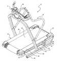
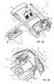
- FIG. 1illustrates a perspective view of a hiking exercise apparatus according to the present invention
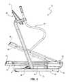
- FIG. 2illustrates a side view of the apparatus of FIG. 1 with the treadbase shown in a neutral position, and a raised position featured in phantom view;
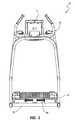
- FIG. 3illustrates a front end view of the apparatus of FIG. 1 ;
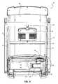
- FIG. 4illustrates a bottom view of the apparatus of FIG. 1 showing the belt motor and braking system
- FIG. 5Ais a bottom perspective view of the apparatus of FIG. 1 showing the position on the apparatus of the belt motor and braking system;
- FIG. 5Bis a cut-way view of the braking system shown in FIG. 5A ;
- FIG. 6Ais a cut-way bottom view of the braking system of FIG. 4 with the magnetic member positioned close to the flywheel;
- FIG. 6Bis a cut-way bottom view of the braking system of FIG. 4 with the magnetic member positioned further away from the flywheel;
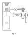
- FIG. 7is a block diagram illustrating how the braking system of FIGS. 4-6B is controlled
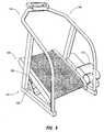
- FIG. 8illustrates a perspective view of an alternate hiking exercise apparatus according to the present invention
- FIG. 9is a front cut-away view of the exercise apparatus of FIG. 8 ;
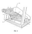
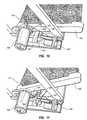
- FIG. 10is a side cut-away view of the exercise apparatus of FIG. 8 with the treadbase shown in a neutral position;
- FIG. 11is another side cut-away view of the exercise apparatus of FIG. 8 with the treadbase shown in an inclined position.
- Exercise apparatus 10can support a user ambulating thereon in a hiking, running, or walking mode.
- exercise apparatus 10is sometimes referred to herein as a hiking or hiker-type exercise apparatus
- exercise apparatus 10can also be a treadmill.
- exercise apparatus 10can be configured such that a user can use exercise apparatus 10 as a treadmill and as a hiker.
- Selectively inclining and declining apparatus 10comprises a support base 12 , a treadbase 14 , and a handrail assembly 16 .
- Support base 12has a proximal end 18 and a distal end 20 .
- Treadbase 14has a proximal end 22 , a distal end 24 , and an inner portion 26 therebetween.
- Treadbase 14is pivotally coupled to support base 12 .
- the length and width of treadbase 14is such that hiking apparatus 10 simulates a hiking motion, yet has a minimal footprint and can be conveniently used and stored in a home or exercise gym.
- treadbase 14in an inclined position, is capable of inclining to extreme angles, such that distal end 24 is high above the neutral position. This enables an exerciser to simulate a hiking motion which requires the user to continually lift the user's knees in an upward, outstretched manner.
- treadbase 14In the neutral position shown in solid line in FIG. 2 , treadbase 14 is substantially parallel to a support surface.
- treadbase 14can also be configured to decline into a declined position in which distal end 24 drops below the neutral position.
- apparatus 10is able to more closely simulate typical mountainous terrain.
- treadbase 14may occur in a variety of different positions depending upon the embodiment. Examples of different coupling positions and embodiments are disclosed in U.S. Pat. No. 6,761,667, entitled “Hiking Exercise Apparatus”, which is incorporated herein by reference in its entirety.
- treadbase 14is pivotally coupled at proximal end 22 to proximal end 18 of support base 12 .
- support basesmay also be employed in the present invention.
- the support baserests on a support surface.
- the treadbaseis mounted thereon.
- Support base 12 of FIGS. 1-5Ais comprised of first and second opposing side members 30 and a cross member 28 extending therebetween. In the illustrated embodiment, cross member 28 is positioned near distal end 20 of support base 12 .
- Treadbase 14may also be comprised of a variety of different members.
- treadbase 14comprises a treadbase frame 32 having first and second longitudinally extending side rails 34 .
- First and second rollers(not shown) extend between proximal and distal ends of first and second side rails 34 , respectively.
- An endless belt 38is movably mounted on the first and second rollers.
- Treadbase frame 32also includes inner portion cross member 40 extending between the center portions of first and second side rails 34 .
- Treadbase 14further comprises a motor 42 coupled to treadbase frame 32 .
- Treadbase 14also comprises a drive belt 44 mounted on (i) a flywheel pulley coupled to motor 42 ; and (ii) a roller pulley coupled to the first roller. Actuation of motor 42 rolls the first roller, thereby turning endless belt 38 .
- Motor 42can have a fan 43 coupled thereto for cooling motor 42 and other components near fan 43 .
- a braking system 50which will be described in greater detail below, can generate heat near motor 42 .
- Fan 43can be adapted to provide cooling to motor 42 and/or braking system 50 .
- Fan 43is coupled to an end of motor 42 and includes multiple blades 45 for moving air as fan 43 rotates.
- Blades 45can be generally flat, angled blades, or blades 45 can be cup-shaped.
- Fan 43can be adapted to move air toward or away from motor 42 and/or braking system 50 .
- Fan 43can be adapted to run continuously or on an as needed basis.
- fan 43can be adapted to run continuously when motor 42 is operating.
- fan 43can be coupled to a rotating shaft of motor 42 .
- fan 43will also rotate, thereby providing cooling to motor 42 .
- fan 43can be adapted to run only when motor 42 exceeds a predetermined temperature.
- fan 43can be adapted to run for a predetermined amount of time.
- fan 43can be configured to provide any needed cooling for motor 42 and/or other components, such as braking system 50 .
- flywheel 54can also provide cooling to motor 42 and/or braking system 50 .
- flywheel 54can include multiple blades 55 and/or apertures 57 therethrough.
- Blades 55can be generally flat, angled blades, or blades 55 can be cup-shaped.
- Blades 55can be adapted to move air toward or away from motor 42 to cool motor 42 .
- apertures 57can be adapted to facilitate the dissipation of heat away from motor 42 , such as by allowing hot air near motor 42 to flow through apertures 57 and away from motor 42 .
- heatcan be generated near the rim or periphery of flywheel 54 . The heat can be transferred by conduction through flywheel 54 to motor 42 .
- the inclusion of apertures 57reduces the amount of material in flywheel 54 through which heat can conducted, thereby reducing the amount of heat transferred from flywheel 54 to motor 42 .
- fan 43 and flywheel 54cooperate to cool motor 42 and/or braking system 50 .
- the blades 45 of fan 43can be adapted to move air toward motor 42
- blades 55 of flywheel 54are adapted to move air away from motor 42 .
- the operation of motor 42generates heat that is transferred to the air surrounding motor 42 .
- Fan 43is adapted to move cooler air toward motor 42 , thereby moving the hot air away from motor 42 .
- Blades 55 of flywheel 54are adapted to draw away the air near motor 42 . Therefore, fan 43 and blades 55 cooperate to move hot air away from motor 42 , which provides a cooling affect to motor 42 .
- Arrow 59 in FIG. 5Billustrates the direction of air flow when fan 43 and blades 55 cooperate in the manner described above. It will be appreciated, however, that fan 43 and/or blades 55 can be adapted to move air in other directions.
- fans 43can be adapted to move air away from motor 42
- blades 55can be adapted to move air towards motor 42 .
- treadbase 14selectively moves between an inclined position (phantom lines in FIG. 2 ) in which distal end 24 is above a neutral position (solid lines in FIG. 2 ) and a declined position, in which distal end is below the neutral position.
- the selective movement of treadbase 14 between the declined, neutral, and inclined positionsis facilitated by pivotally coupling proximal end 22 of treadbase 14 to proximal end 18 of support base 12 .
- pivotal couplingcan be accomplished, for example, through the use of a bracket 36 that is pivotally connected at opposing ends to base 12 and treadbase 14 and through the use of inclination motor 48 .
- Hiking apparatus 10is able to achieve an improved inclining/declining dynamic without requiring the use of a high stack of moving steps, paddles or foot supports. Instead, a vigorous hiking dynamic can be achieved in a significantly shorter room because clearance for steps, paddles, and supports is not necessary.
- the moving beltwhich acts as the ambulating surface for a user, can be adjacent the support surface even in the most intensely angled position.
- an exerciserBy moving between the relatively extreme inclination ranges available with apparatus 10 , an exerciser is able to simulate a hike or journey through a variety of different slopes and angles.
- the amount of inclination/declinationcan be controlled by an electronic control system 46 electrically coupled to inclination motor 48 discussed below.
- Electronic control system 46can also controls belt speed and a variety of other features.
- the aspect ratioi.e., the length and width of treadbase 14 is such that hiking apparatus 10 simulates a hiking motion, yet has a minimal footprint and can be conveniently used and stored in a home or exercise gym.
- belt 38is wider than typical treadmill belts. This dynamic provides an exerciser with lateral movement which is highly desirable during hiking, such as during inclining, declining and ambulating over rough terrain. Examples of some aspect ratios that can be used with apparatus 10 are disclosed in U.S. Pat. No. 6,761,667, entitled “Hiking Exercise Apparatus”, which is incorporated herein by reference in its entirety.
- the means for selectively moving treadbase 14 relative to support base 12comprises inclination motor 48 or another linear extending assembly.
- Inclination motor 48is pivotally coupled to support base 12 at one end thereof and pivotally coupled to treadbase 14 at an opposing end thereof. More particularly, in the illustrated embodiment motor 48 is pivotally coupled to cross member 28 of support base 12 and inner portion cross member 40 of treadbase 14 .
- treadbase 14moves to a declined position such that distal end 24 of treadbase 14 is positioned below the neutral position.
- inclination motor 48is selectively extended to an extended position, as shown in phantom lines in FIG. 2 , treadbase 14 is inclined such that distal end 24 of treadbase 14 is positioned above the neutral position.
- inclination motor 48is pivotally coupled to the inner portion of treadbase 14 (remotely from the ends) to facilitate the incline and decline of treadbase 14 .
- This positioning of inclination motor 48does not interfere with distal end 24 as it is lowered or raised.
- distal end 24is able to be moved adjacent to the support surface without interference from a coupling mechanism.
- an endless beltis the ambulating surface, rather than a series of steps, paddles or foot supports, there is no requirement for the additional clearance space otherwise required for steps, paddles or supports. This conserves space and enables a user to achieve a significantly inclined workout without requiring the exercise device to be overly tall.
- hiking apparatus 10further comprises a braking system 50 which prevents belt 38 of treadbase 14 from being moved by a user faster than a certain desired speed. While braking system 50 is described herein as a magnetic braking system, it will be appreciated that braking system 50 can be an eddy braking system.
- braking system 50is mounted to treadbase frame 32 adjacent motor 42 .
- Braking system 50comprises a magnetic member 52 that can be selectively moved relative to the flywheel 54 of motor 42 .
- the magnetic force experienced by flywheel 54increases, which causes the rotational speed of flywheel 54 to decrease.
- the decreased rotational speed of flywheel 54in turn decreases the speed of belt 38 .
- belt 38begins to move at a faster than desired rate
- magnetic member 52is moved closer to flywheel 54 until belt 38 slows to the desired speed.
- braking system 50includes a bracket 56 which is coupled to treadbase 14 . Coupled to bracket 56 are the various components of braking system 50 , such as a braking motor 58 , a guide rod 60 , and a lead screw 62 . Guide rod 60 and lead screw 62 are mounted in bracket 56 such that they are positioned substantially parallel to one another. Furthermore, guide rod 60 and lead screw 62 are mounted such that they are substantially parallel to a longitudinal axis of belt motor 42 and a rotational axis of flywheel 54 .
- Braking system 50This orientation and positioning of braking system 50 , and in particular guide rod 60 and lead screw 62 , relative to motor 42 allows for braking system 50 to occupy a minimal amount of space under treadbase 14 , thereby enabling the overall size and height of apparatus 10 to be minimized.
- Braking systemfurther includes sensors 61 and 63 which function as limit switches as described below.
- Magnetic member 52is moveably mounted within bracket 56 and on guide rod 60 and lead screw 62 . As illustrated in the Figures, magnetic member 52 can be securely mounted to bracket 56 and lead screw 62 by way of bolts 53 . Bolts 53 prevent magnetic member 52 from moving laterally relative to lead screw 62 . Magnetic member 52 is slidably mounted on guide rod 60 and threadably mounted on lead screw 62 . In this configuration, rotation by braking motor 58 of lead screw 62 about the longitudinal axis of lead screw 62 causes magnetic member 52 to move along the length of lead screw 62 while guide rod 60 prevents magnetic member 52 from rotating about lead screw 62 .
- magnetic member 52moves along guide rod 60 and lead screw 62 is a direction that is generally parallel to a rotational axis A of flywheel 54 . In this manner magnetic member 52 can move between a first position with respect to flywheel 54 and a second position that is closer to flywheel 54 than the first position.
- braking system 50works in one embodiment.
- a userstands upon treadbase 14 and selects a desired incline and speed for treadbase 14 and belt 38 . Selection of the desired incline and speed can be made at console 11 ( FIGS. 1-3 ), which includes or is in communication with electronic control system 46 .
- electronic control system 46adjusts the incline of treadbase 14 and begins to rotate belt 38 .
- electronic control system 46can send a signal to inclination motor 48 to adjust the incline of treadbase 14 .
- electronic control system 46can also send a signal to motor 42 to adjust the speed of belt 38 .
- the braking system 50prevents belt 38 from exceeding a certain speed so that a user does not fall off of apparatus 10 .
- the braking system 50is useful at inclines such as in excess of about 11% grade and is particularly useful at high inclines, such as in excess of about 25% grade.
- electronic control system 46includes a current monitor and controller 64 in electrical communication with a motor controller 66 and braking motor 58 .
- Motor controller 66provides the current to operate motor 42 , which drives belt 38 .
- Braking motor 58controls the movement of lead screw 62 .
- current monitor and controller 64monitors the amount of current being drawn from motor control 66 by motor 42 .
- the current being drawn from motor control 66will remain at a generally constant level or within a predetermined range.
- current monitor and controller 64will take no action except to continue monitoring the current flowing to motor 42 .
- current monitor and controller 64can include Hall Effect sensors, shunt resistors, and/or electromagnetic current sensors. It will be appreciated that other means for detecting current levels can also be used in current monitor and controller 64 .
- current monitor and controller 64When current monitor and controller 64 detects a drop in current drawn by motor 42 , current monitor and controller 64 sends a signal to braking motor 58 to increase the amount of braking provided. In response to the signal from current monitor and controller 64 , braking motor 58 rotates lead screw 62 in a first direction, which causes magnetic member 52 to move closer to flywheel 54 , such as to the position shown in FIGS. 5B and 6A .
- Flywheel 54preferably has a strip of copper thereon or another nonferrous metal. As magnetic member 52 moves closer to flywheel 54 , the magnetic forces therebetween increase. The increased magnetic force causes the rotational speed of flywheel 54 to decrease. As appreciated by one of ordinary skill in the art, the rotational speed of flywheel 54 is directly related to the speed of belt 38 . Thus, as the rotational speed of flywheel 54 decreases, the speed of belt 38 will also decrease.
- current monitor and controller 64can send a signal to braking motor 58 to reduce the amount of braking being provided.
- braking motor 58rotates lead screw 62 in a second direction, which causes magnetic member 52 to move further away from flywheel 54 , such as to the position shown in FIG. 6B .
- the magnetic forces therebetweendecrease.
- the decreased magnetic forcedecreases the amount of braking, thereby allowing the rotational speed of flywheel 54 , and thus belt 38 , to increase.
- braking system 50can regulate the speed of belt 38 to prevent belt 38 from rotating too fast and potentially causing a user to fall off of treadbase 14 .
- braking system 50can also provide a continuously variable amount of braking.
- the amount of braking provided by braking system 50can be incrementally adjusted as well.
- Braking system 50is one example of braking means for slowing the speed of the treadbase.
- braking system 50can include sensors 61 and 63 which act as limit switches. More specifically, sensors 61 and 63 are adapted to detect when magnetic member 52 is positioned at an extreme end of lead screw 62 . When magnetic member 52 is positioned at an extreme end of lead screw 62 , sensor 61 or 63 will detect the position of magnetic member 52 and deactivate brake motor 58 . Deactivation of brake motor 58 causes lead screw 62 to stop rotating, which in turn stops movement of magnetic member 52 along lead screw 62 . Sensors 61 and 63 are thus adapted to prevent brake motor 58 from continuing to operate when magnetic member 52 is positioned at an extreme end of lead screw 62 .
- a minimal amount of brakingis desired when treadbase 14 is inclined at or below a grade of approximately 11% or 12%.
- magnetic member 52is moved as far away from flywheel 54 as possible. It will be appreciated, however, that magnetic member 52 can only move to the extreme ends of lead screw 62 .
- sensor 61deactivates brake motor 58 when sensor 61 detects magnetic member 52 at the extreme end of lead screw 62 .
- Sensor 63functions in a similar manner when the maximum amount of braking is desired. In particular, magnetic member 52 provides the most braking when magnetic member 52 is positioned next to sensor 63 .
- sensor 63detects magnetic member 52 next to sensor 63 , sensor 63 deactivates brake motor 58 to prevent brake motor 58 from trying to move magnetic member 52 even further along lead screw 62 . It will be appreciated that in other embodiments the minimal amount of braking is desired at other grades based on the specifications of the device.
- magnetic member 52is mounted within bracket 56 in a position similar to that shown in FIG. 6A .
- magnetic member 52can be an electromagnet that can be turned on, off, or otherwise adjusted to change the amount of braking being provided. In such an embodiment, magnetic member 52 can remain stationary relative to flywheel 54 , thereby decreasing the number of moving parts within braking system 50 .
- the manner in which the braking is adjusted when magnetic member 52 is an electromagnetis similar to that described above when magnetic member 52 moves relative to flywheel 54 .
- current monitor and controller 64monitors the amount of current being drawn by motor 42 . When the current changes, current monitor and controller 64 adjusts the strength of electromagnetic member 52 . As the magnetic field of electromagnet 52 changes, the rotational speed of flywheel 54 changes as described above. Specifically, when the current used by motor 42 drops, the strength of the magnetic field produced by magnetic member 52 is increased, thereby increasing the amount of braking provided. Conversely, when the current used by motor 42 increases, the strength of the magnetic field produced by magnetic member 52 is reduced, thereby reducing the amount of braking provided. Additionally, the amount of braking provided can be continuously variable or incrementally adjusted by adjusting the magnetic field strength produced by the magnetic member 52 .
- Apparatus 141comprises a support base 142 , a treadbase 144 movably coupled at a proximal end thereof to support base 142 and handrail assembly 146 coupled to support base 142 .
- the means for selectively moving treadbase 144 shown in FIGS. 8-11comprises (i) a linear extending assembly in the form of an extension motor 164 ( FIGS. 10-11 ); and (ii) a pivoting lever 148 .
- Motor 164is pivotally coupled to base 142 at one end thereof and pivotally coupled to pivoting lever 148 at an opposing end.
- Pivoting lever 148is pivotally coupled at a lower end thereof 112 to support base and has at an upper end thereof a rotating wheel 150 ( FIGS. 8-9 ).
- Wheel 150rolls against treadbase 104 .
- Rolling belt guides 151 on opposing sides of the endless beltmaintain the belt in a desired, aligned position on the treadbase rollers
- Each guide 151comprises a wheel rolling on an axle.
- lever 148Upon selective contraction of linear extending assembly 164 as shown in FIG. 10 , lever 148 is moved downwardly. When extension motor 164 is selectively extended to an extended mode, as shown in FIG. 11 , lever 148 is in an upward position such that the position of treadbase 144 is inclined. In one embodiment, as shown in FIG. 9 , first and second levers 148 , 149 having wheels thereon are coupled to opposing sides of support base 142 such that each end of treadbase 144 receives a rolling lever thereon. However, a single lever 148 may also be employed. Also as shown in FIGS. 10 and 11 (which is shown in a cut-away view from a side thereof with a cosmetic hood 152 shown in FIGS. 8-9 removed), beam 166 of lever 149 is coupled to a lever bracket 168 by a cross member which extends through a sleeve 170 coupled to support base 142 . Extension motor 164 is pivotally coupled to bracket 168 .
- hiking apparatus 141further comprises a braking system 154 which prevents the belt of treadbase 144 from being moved by a user faster than a certain desired speed.
- Braking system 154comprises an eddy magnet comprising a magnetic member 158 coupled adjacent the flywheel 160 of motor 156 . Magnetic member 158 is secured in a desired position by a cord 162 coupled to base 142 .
- Braking system 154is adapted to regulate or control the rotational speed of flywheel 160 and the belt of treadbase 144 . More specifically, magnetic member 158 is adapted to move between a first position close to flywheel 160 , as shown in FIG. 10 , and a second position further away from flywheel 160 , as shown in FIG. 11 . Braking system 154 provides a greater amount of braking force when magnetic member 158 is in the first position as compared to the amount of braking provided when magnetic member 158 is in the second position. In particular, the magnetic force experienced by flywheel 160 when magnetic member 154 is close to flywheel 160 is larger than the magnetic force experienced by flywheel 160 when magnetic member 154 is further away from flywheel 160 . The rotational speed of flywheel 160 decreases as the magnetic force increases. Thus, the rotational speed of flywheel 160 can be selectively adjusted by adjusting the position of magnetic member 154 relative to flywheel 160 .
- a variety of other braking means for slowing the speed of the treadbaseare also available for use on the apparatuses disclosed herein, such as a friction brake, a gear brake, a disk brake, a band, a motor which drives in an opposite direction, a portion of a motor which is an integral braking system, a motor geared not to exceed a certain speed, and a variety of other such assemblies, and a variety of other braking systems such as the braking systems disclosed in U.S. patent application Ser. No. 09/496,560, entitled “System and Method for Selective Adjustment of Exercise Apparatus,” filed on Feb. 2, 2000, now U.S. Pat. No. 6,447,424, which is incorporated herein by reference in its entirety.
- a handrail assemblysuch as handrail assembly 16 or 146 , of the present invention may be a single handrail (i.e., held by one hand only), first and second handrails coupled to each other, a single handrail with a motor attached thereto, first and second handrails each with a motor coupled thereto, a two-part assembly, a telescoping assembly, a solid handrail, a tubular handrail, or a variety of other handrails, each of which are also examples of means for supporting at least one arm of a user ambulating on the treadbase.
- Examples of various types of handrail assembliesare disclosed in U.S. Pat. No. 6,761,667, entitled “Hiking Exercise Apparatus”, which is incorporated herein by reference in its entirety.
- the frames of the apparatuses hereinmay include wheels thereon for moving the apparatuses, such as on the support bases.
Landscapes
- Health & Medical Sciences (AREA)
- General Health & Medical Sciences (AREA)
- Physical Education & Sports Medicine (AREA)
- Cardiology (AREA)
- Vascular Medicine (AREA)
- Life Sciences & Earth Sciences (AREA)
- Biophysics (AREA)
- Orthopedic Medicine & Surgery (AREA)
- Physics & Mathematics (AREA)
- Electromagnetism (AREA)
- Rehabilitation Tools (AREA)
Abstract
Description
Claims (33)
Priority Applications (3)
| Application Number | Priority Date | Filing Date | Title |
|---|---|---|---|
| US12/340,407US7862483B2 (en) | 2000-02-02 | 2008-12-19 | Inclining treadmill with magnetic braking system |
| US12/975,682US8876668B2 (en) | 2000-02-02 | 2010-12-22 | Exercise device with magnetic braking system |
| US14/531,821US9623281B2 (en) | 2000-02-02 | 2014-11-03 | Exercise device with braking system |
Applications Claiming Priority (4)
| Application Number | Priority Date | Filing Date | Title |
|---|---|---|---|
| US09/496,569US6761667B1 (en) | 2000-02-02 | 2000-02-02 | Hiking exercise apparatus |
| US54243704P | 2004-02-06 | 2004-02-06 | |
| US10/788,799US7537549B2 (en) | 2000-02-02 | 2004-02-27 | Incline assembly with cam |
| US12/340,407US7862483B2 (en) | 2000-02-02 | 2008-12-19 | Inclining treadmill with magnetic braking system |
Related Parent Applications (1)
| Application Number | Title | Priority Date | Filing Date |
|---|---|---|---|
| US10/788,799Continuation-In-PartUS7537549B2 (en) | 2000-02-02 | 2004-02-27 | Incline assembly with cam |
Related Child Applications (1)
| Application Number | Title | Priority Date | Filing Date |
|---|---|---|---|
| US12/975,682ContinuationUS8876668B2 (en) | 2000-02-02 | 2010-12-22 | Exercise device with magnetic braking system |
Publications (2)
| Publication Number | Publication Date |
|---|---|
| US20090137367A1 US20090137367A1 (en) | 2009-05-28 |
| US7862483B2true US7862483B2 (en) | 2011-01-04 |
Family
ID=46332093
Family Applications (3)
| Application Number | Title | Priority Date | Filing Date |
|---|---|---|---|
| US12/340,407Expired - Fee RelatedUS7862483B2 (en) | 2000-02-02 | 2008-12-19 | Inclining treadmill with magnetic braking system |
| US12/975,682Expired - Fee RelatedUS8876668B2 (en) | 2000-02-02 | 2010-12-22 | Exercise device with magnetic braking system |
| US14/531,821Expired - Fee RelatedUS9623281B2 (en) | 2000-02-02 | 2014-11-03 | Exercise device with braking system |
Family Applications After (2)
| Application Number | Title | Priority Date | Filing Date |
|---|---|---|---|
| US12/975,682Expired - Fee RelatedUS8876668B2 (en) | 2000-02-02 | 2010-12-22 | Exercise device with magnetic braking system |
| US14/531,821Expired - Fee RelatedUS9623281B2 (en) | 2000-02-02 | 2014-11-03 | Exercise device with braking system |
Country Status (1)
| Country | Link |
|---|---|
| US (3) | US7862483B2 (en) |
Cited By (78)
| Publication number | Priority date | Publication date | Assignee | Title |
|---|---|---|---|---|
| US20100222182A1 (en)* | 2007-10-16 | 2010-09-02 | Dasan Rnd Co., Ltd. | Treadmill with automatic speed control and control module of the same |
| US20110152039A1 (en)* | 2000-02-02 | 2011-06-23 | Icon Ip, Inc. | Exercise device with magnetic braking system |
| US20130017929A1 (en)* | 2011-07-12 | 2013-01-17 | Icon Health & Fitness, Inc. | Exercise device with inclination adjusting mechanism |
| WO2013074243A1 (en) | 2011-11-15 | 2013-05-23 | Icon Health & Fitness, Inc. | Exercise device with rack and pinion incline adjusting mechanism |
| US20150182782A1 (en)* | 2013-12-31 | 2015-07-02 | Icon Health & Fitness, Inc. | Locking Mechanism for a Vertically Storable Exercise Machine |
| WO2015116851A1 (en)* | 2014-01-30 | 2015-08-06 | Icon Health & Fitness, Inc. | Low profile collapsible treadmill |
| US9174085B2 (en) | 2012-07-31 | 2015-11-03 | John Paul Foley | Exercise system and method |
| WO2018129074A1 (en)* | 2017-01-03 | 2018-07-12 | True Fitness Technology, Inc. | Mechanical braking system for exercise machines |
| US10188890B2 (en) | 2013-12-26 | 2019-01-29 | Icon Health & Fitness, Inc. | Magnetic resistance mechanism in a cable machine |
| US10220259B2 (en) | 2012-01-05 | 2019-03-05 | Icon Health & Fitness, Inc. | System and method for controlling an exercise device |
| US10226396B2 (en) | 2014-06-20 | 2019-03-12 | Icon Health & Fitness, Inc. | Post workout massage device |
| US10238911B2 (en) | 2016-07-01 | 2019-03-26 | Woodway Usa, Inc. | Motorized treadmill with motor braking mechanism and methods of operating same |
| US10252109B2 (en) | 2016-05-13 | 2019-04-09 | Icon Health & Fitness, Inc. | Weight platform treadmill |
| US10258828B2 (en) | 2015-01-16 | 2019-04-16 | Icon Health & Fitness, Inc. | Controls for an exercise device |
| US10265566B2 (en) | 2009-03-17 | 2019-04-23 | Woodway Usa, Inc. | Manual treadmill and methods of operating the same |
| US10272317B2 (en) | 2016-03-18 | 2019-04-30 | Icon Health & Fitness, Inc. | Lighted pace feature in a treadmill |
| US10279212B2 (en) | 2013-03-14 | 2019-05-07 | Icon Health & Fitness, Inc. | Strength training apparatus with flywheel and related methods |
| US10293211B2 (en) | 2016-03-18 | 2019-05-21 | Icon Health & Fitness, Inc. | Coordinated weight selection |
| US10343017B2 (en) | 2016-11-01 | 2019-07-09 | Icon Health & Fitness, Inc. | Distance sensor for console positioning |
| US10376736B2 (en) | 2016-10-12 | 2019-08-13 | Icon Health & Fitness, Inc. | Cooling an exercise device during a dive motor runway condition |
| US10391361B2 (en) | 2015-02-27 | 2019-08-27 | Icon Health & Fitness, Inc. | Simulating real-world terrain on an exercise device |
| US10398932B2 (en) | 2015-12-31 | 2019-09-03 | Nautilus, Inc. | Treadmill including a lift assistance mechanism |
| US10426989B2 (en) | 2014-06-09 | 2019-10-01 | Icon Health & Fitness, Inc. | Cable system incorporated into a treadmill |
| US10433612B2 (en) | 2014-03-10 | 2019-10-08 | Icon Health & Fitness, Inc. | Pressure sensor to quantify work |
| US10441844B2 (en) | 2016-07-01 | 2019-10-15 | Icon Health & Fitness, Inc. | Cooling systems and methods for exercise equipment |
| US10441840B2 (en) | 2016-03-18 | 2019-10-15 | Icon Health & Fitness, Inc. | Collapsible strength exercise machine |
| US10449416B2 (en) | 2015-08-26 | 2019-10-22 | Icon Health & Fitness, Inc. | Strength exercise mechanisms |
| US10471299B2 (en) | 2016-07-01 | 2019-11-12 | Icon Health & Fitness, Inc. | Systems and methods for cooling internal exercise equipment components |
| US10478660B2 (en) | 2015-05-27 | 2019-11-19 | Woodway Usa, Inc. | Recumbent therapeutic and exercise device |
| US10493349B2 (en) | 2016-03-18 | 2019-12-03 | Icon Health & Fitness, Inc. | Display on exercise device |
| US10500473B2 (en) | 2016-10-10 | 2019-12-10 | Icon Health & Fitness, Inc. | Console positioning |
| US10537764B2 (en) | 2015-08-07 | 2020-01-21 | Icon Health & Fitness, Inc. | Emergency stop with magnetic brake for an exercise device |
| US10561894B2 (en) | 2016-03-18 | 2020-02-18 | Icon Health & Fitness, Inc. | Treadmill with removable supports |
| US10561877B2 (en) | 2016-11-01 | 2020-02-18 | Icon Health & Fitness, Inc. | Drop-in pivot configuration for stationary bike |
| US10561893B2 (en) | 2016-10-12 | 2020-02-18 | Icon Health & Fitness, Inc. | Linear bearing for console positioning |
| US10625137B2 (en) | 2016-03-18 | 2020-04-21 | Icon Health & Fitness, Inc. | Coordinated displays in an exercise device |
| US10625114B2 (en) | 2016-11-01 | 2020-04-21 | Icon Health & Fitness, Inc. | Elliptical and stationary bicycle apparatus including row functionality |
| US10661114B2 (en) | 2016-11-01 | 2020-05-26 | Icon Health & Fitness, Inc. | Body weight lift mechanism on treadmill |
| US10671705B2 (en) | 2016-09-28 | 2020-06-02 | Icon Health & Fitness, Inc. | Customizing recipe recommendations |
| US10709926B2 (en) | 2015-10-06 | 2020-07-14 | Woodway Usa, Inc. | Treadmill |
| US10729965B2 (en) | 2017-12-22 | 2020-08-04 | Icon Health & Fitness, Inc. | Audible belt guide in a treadmill |
| US10786706B2 (en) | 2018-07-13 | 2020-09-29 | Icon Health & Fitness, Inc. | Cycling shoe power sensors |
| US10918905B2 (en) | 2016-10-12 | 2021-02-16 | Icon Health & Fitness, Inc. | Systems and methods for reducing runaway resistance on an exercise device |
| US10940360B2 (en) | 2015-08-26 | 2021-03-09 | Icon Health & Fitness, Inc. | Strength exercise mechanisms |
| US10953305B2 (en) | 2015-08-26 | 2021-03-23 | Icon Health & Fitness, Inc. | Strength exercise mechanisms |
| US11000730B2 (en) | 2018-03-16 | 2021-05-11 | Icon Health & Fitness, Inc. | Elliptical exercise machine |
| US11033777B1 (en) | 2019-02-12 | 2021-06-15 | Icon Health & Fitness, Inc. | Stationary exercise machine |
| US11058913B2 (en) | 2017-12-22 | 2021-07-13 | Icon Health & Fitness, Inc. | Inclinable exercise machine |
| US11058914B2 (en) | 2016-07-01 | 2021-07-13 | Icon Health & Fitness, Inc. | Cooling methods for exercise equipment |
| US11065503B2 (en)* | 2017-02-13 | 2021-07-20 | Woodway Usa, Inc. | Handrail configuration for a treadmill |
| USD930089S1 (en) | 2019-03-12 | 2021-09-07 | Woodway Usa, Inc. | Treadmill |
| US11187285B2 (en) | 2017-12-09 | 2021-11-30 | Icon Health & Fitness, Inc. | Systems and methods for selectively rotationally fixing a pedaled drivetrain |
| US11244751B2 (en) | 2012-10-19 | 2022-02-08 | Finish Time Holdings, Llc | Method and device for providing a person with training data of an athlete as the athlete is performing a swimming workout |
| US11298577B2 (en) | 2019-02-11 | 2022-04-12 | Ifit Inc. | Cable and power rack exercise machine |
| US11298284B2 (en) | 2017-02-10 | 2022-04-12 | Woodway Usa, Inc. | Motorized recumbent therapeutic and exercise device |
| US11326673B2 (en) | 2018-06-11 | 2022-05-10 | Ifit Inc. | Increased durability linear actuator |
| US11338188B2 (en) | 2018-01-18 | 2022-05-24 | True Fitness Technology, Inc. | Braking mechanism for a self-powered treadmill |
| US11451108B2 (en) | 2017-08-16 | 2022-09-20 | Ifit Inc. | Systems and methods for axial impact resistance in electric motors |
| US11534651B2 (en) | 2019-08-15 | 2022-12-27 | Ifit Inc. | Adjustable dumbbell system |
| US11534654B2 (en) | 2019-01-25 | 2022-12-27 | Ifit Inc. | Systems and methods for an interactive pedaled exercise device |
| US11610664B2 (en) | 2012-07-31 | 2023-03-21 | Peloton Interactive, Inc. | Exercise system and method |
| US11673036B2 (en) | 2019-11-12 | 2023-06-13 | Ifit Inc. | Exercise storage system |
| US11794070B2 (en) | 2019-05-23 | 2023-10-24 | Ifit Inc. | Systems and methods for cooling an exercise device |
| US11850497B2 (en) | 2019-10-11 | 2023-12-26 | Ifit Inc. | Modular exercise device |
| US20240009508A1 (en)* | 2018-05-21 | 2024-01-11 | The Giovanni Project LLC | Braking and Locking System for a Treadmill |
| US11878199B2 (en) | 2021-02-16 | 2024-01-23 | Ifit Inc. | Safety mechanism for an adjustable dumbbell |
| US11931621B2 (en) | 2020-03-18 | 2024-03-19 | Ifit Inc. | Systems and methods for treadmill drift avoidance |
| US11951377B2 (en) | 2020-03-24 | 2024-04-09 | Ifit Inc. | Leaderboard with irregularity flags in an exercise machine system |
| US12029961B2 (en) | 2020-03-24 | 2024-07-09 | Ifit Inc. | Flagging irregularities in user performance in an exercise machine system |
| US12029935B2 (en) | 2021-08-19 | 2024-07-09 | Ifit Inc. | Adjustment mechanism for an adjustable kettlebell |
| US12176009B2 (en) | 2021-12-30 | 2024-12-24 | Ifit Inc. | Systems and methods for synchronizing workout equipment with video files |
| US12219201B2 (en) | 2021-08-05 | 2025-02-04 | Ifit Inc. | Synchronizing video workout programs across multiple devices |
| US12263371B2 (en) | 2021-04-27 | 2025-04-01 | Ifit Inc. | Devices, systems, and methods for rotating a tread belt in two directions |
| US12280294B2 (en) | 2021-10-15 | 2025-04-22 | Ifit Inc. | Magnetic clutch for a pedaled drivetrain |
| US12350547B2 (en) | 2022-02-28 | 2025-07-08 | Ifit Inc. | Devices, systems, and methods for moving a movable step through a transition zone |
| US12350573B2 (en) | 2021-04-27 | 2025-07-08 | Ifit Inc. | Systems and methods for cross-training on exercise devices |
| US12409375B2 (en) | 2022-03-18 | 2025-09-09 | Ifit Inc. | Systems and methods for haptic simulation in incline exercise devices |
| US12433815B2 (en) | 2020-10-02 | 2025-10-07 | Ifit Inc. | Massage roller with pressure sensors |
Families Citing this family (30)
| Publication number | Priority date | Publication date | Assignee | Title |
|---|---|---|---|---|
| WO2013163044A1 (en)* | 2012-04-23 | 2013-10-31 | Icon Health & Fitness, Inc. | Exercise systems for simulating outdoor terrain |
| US9999818B2 (en) | 2012-08-27 | 2018-06-19 | Wahoo Fitness Llc | Bicycle trainer |
| EA033860B1 (en)* | 2014-12-19 | 2019-12-02 | Тру Фитнесс Текнолоджи, Инк. | High-incline treadmill |
| US10032227B2 (en)* | 2014-12-30 | 2018-07-24 | Johnson Health Tech Co., Ltd. | Exercise apparatus with exercise use verification function and verifying method |
| US11995725B2 (en) | 2014-12-30 | 2024-05-28 | Johnson Health Tech Co., Ltd. | Exercise apparatus with exercise use verification function and verifying method |
| US12141876B2 (en)* | 2014-12-30 | 2024-11-12 | Johnson Health Tech Co., Ltd. | Exercise apparatus with exercise use verification function and verifying method |
| US10398933B2 (en)* | 2015-06-01 | 2019-09-03 | Johnson Health Tech Co., Ltd. | Exercise apparatus |
| US9814930B2 (en)* | 2015-06-01 | 2017-11-14 | Johnson Health Tech Co., Ltd. | Exercise apparatus |
| US12005302B2 (en) | 2015-06-01 | 2024-06-11 | Johnson Health Tech Co., Ltd | Exercise apparatus |
| US11154746B2 (en) | 2015-06-01 | 2021-10-26 | Johnson Health Tech Co., Ltd. | Exercise apparatus |
| US10046202B2 (en) | 2015-07-02 | 2018-08-14 | Digital Concepts Of Missouri, Inc. | Incline trainer safety brake |
| CN106310589B (en)* | 2015-07-03 | 2018-11-27 | 乔山健身器材(上海)有限公司 | sports equipment |
| US10065062B2 (en) | 2015-10-12 | 2018-09-04 | Precor Incorporated | Exercise apparatus with eddy current rail |
| US10668314B2 (en) | 2015-10-16 | 2020-06-02 | Precor Incorporated | Variable distance eddy current braking system |
| ITUB20159645A1 (en)* | 2015-12-17 | 2017-06-17 | Technogym Spa | Braking system for exercise machines and relative method of operation. |
| US10391348B2 (en) | 2016-02-01 | 2019-08-27 | Mad Dogg Athletics, Inc. | Adjustable resistance and braking system for exercise equipment |
| US10369449B2 (en)* | 2016-09-02 | 2019-08-06 | True Fitness Technology, Inc. | Braking systems for exercise machines |
| US10207148B2 (en)* | 2016-10-12 | 2019-02-19 | Icon Health & Fitness, Inc. | Systems and methods for reducing runaway resistance on an exercise device |
| TWI680782B (en) | 2016-12-05 | 2020-01-01 | 美商愛康運動與健康公司 | Offsetting treadmill deck weight during operation |
| TWI672164B (en) | 2016-12-05 | 2019-09-21 | 美商愛康運動與健康公司 | Tread belt locking mechanism |
| US10702736B2 (en) | 2017-01-14 | 2020-07-07 | Icon Health & Fitness, Inc. | Exercise cycle |
| TWI617338B (en)* | 2017-01-19 | 2018-03-11 | 力山工業股份有限公司 | Treadmill |
| US10272280B2 (en) | 2017-02-16 | 2019-04-30 | Technogym S.P.A. | Braking system for gymnastic machines and operating method thereof |
| CN108042980B (en)* | 2017-10-27 | 2020-09-29 | 浦江县汕淋贸易有限公司 | Balance roller |
| US10758775B2 (en) | 2018-05-21 | 2020-09-01 | The Giovanni Project LLC | Braking and locking system for a treadmill |
| US11224781B2 (en) | 2019-02-28 | 2022-01-18 | The Giovanni Project LLC | Treadmill with lighted slats and power disks |
| US11291881B2 (en) | 2019-02-28 | 2022-04-05 | The Giovanni Project LLC | Treadmill with lighted slats |
| CN110152240B (en)* | 2019-06-26 | 2021-05-04 | 中大体育产业集团股份有限公司 | Treadmill power system and treadmill thereof |
| CN211461933U (en)* | 2019-11-08 | 2020-09-11 | 乔山健身器材(上海)有限公司 | Electric running machine |
| CN214544071U (en)* | 2020-12-08 | 2021-10-29 | 乔山健身器材(上海)有限公司 | Motor braking device for sports equipment |
Citations (106)
| Publication number | Priority date | Publication date | Assignee | Title |
|---|---|---|---|---|
| US3592466A (en) | 1969-01-21 | 1971-07-13 | Billie D Parsons | Revolving step exerciser with adjustable slope |
| US3602502A (en) | 1968-10-18 | 1971-08-31 | Erich Jaegar | Moving belt ergometer with braking arrangement |
| US3869121A (en)* | 1972-07-10 | 1975-03-04 | Evan R Flavell | Proportioned resistance exercise servo system |
| US3903613A (en) | 1974-02-07 | 1975-09-09 | Aaron M Bisberg | Bicycle training device for simulating the movement of a bicycle equipped with gears |
| US4151988A (en) | 1977-05-26 | 1979-05-01 | Nabinger Herman G | Brake mechanism for a treadmill |
| US4358105A (en) | 1980-08-21 | 1982-11-09 | Lifecycle, Inc. | Programmed exerciser apparatus and method |
| US4408613A (en) | 1981-10-02 | 1983-10-11 | Aerobitronics, Inc. | Interactive exercise device |
| US4544152A (en) | 1983-07-25 | 1985-10-01 | Taitel Charles M | Passive-type treadmill |
| US4659074A (en) | 1985-03-14 | 1987-04-21 | Landice Products, Inc. | Passive-type treadmill having an improved governor assembly and an electromagnetic speedometer integrated into the flywheel assembly |
| US4659078A (en) | 1983-09-09 | 1987-04-21 | Blome Victor S | Fluid dynamic exerciser |
| US4687195A (en) | 1984-02-06 | 1987-08-18 | Tri-Tech, Inc. | Treadmill exerciser |
| US4708337A (en) | 1985-12-20 | 1987-11-24 | Industrial Technology Research Institute | Automatic treadmill |
| US4759540A (en) | 1986-10-14 | 1988-07-26 | Industrial Technology Research Institute | Compact structure for a treadmill |
| US4786049A (en) | 1986-09-02 | 1988-11-22 | Keiper Dynavit Gmbh & Co. | Bicycle ergometer |
| US4790528A (en) | 1986-07-29 | 1988-12-13 | Combi Co., Ltd. | Training device for rehabilitation |
| US4828257A (en) | 1986-05-20 | 1989-05-09 | Powercise International Corporation | Electronically controlled exercise system |
| US4842266A (en) | 1986-08-27 | 1989-06-27 | Sweeney Sr James S | Physical exercise apparatus having motivational display |
| US4848737A (en) | 1987-10-01 | 1989-07-18 | Ehrenfield Ted R | Cardiovascular exercise ladder |
| US4869497A (en) | 1987-01-20 | 1989-09-26 | Universal Gym Equipment, Inc. | Computer controlled exercise machine |
| US4913396A (en) | 1988-10-12 | 1990-04-03 | Weslo, Inc. | Adjustable incline system for exercise equipment |
| US4927136A (en) | 1989-01-06 | 1990-05-22 | Engineering Dynamics Corporation | Braking system for exercise apparatus |
| US4934692A (en)* | 1986-04-29 | 1990-06-19 | Robert M. Greening, Jr. | Exercise apparatus providing resistance variable during operation |
| US4941652A (en)* | 1987-02-09 | 1990-07-17 | Nintendo Co., Ltd. | Bicycle type training machine |
| US4998725A (en) | 1989-02-03 | 1991-03-12 | Proform Fitness Products, Inc. | Exercise machine controller |
| US5029801A (en) | 1988-10-12 | 1991-07-09 | Proform Fitness Products, Inc. | Adjustable incline system for exercise equipment |
| US5062632A (en)* | 1989-12-22 | 1991-11-05 | Proform Fitness Products, Inc. | User programmable exercise machine |
| US5067710A (en) | 1989-02-03 | 1991-11-26 | Proform Fitness Products, Inc. | Computerized exercise machine |
| US5085426A (en) | 1990-07-30 | 1992-02-04 | Precor Incorporated | Integrated drive and elevation system for exercise apparatus |
| US5088729A (en) | 1990-02-14 | 1992-02-18 | Weslo, Inc. | Treadmill frame and roller bracket assembly |
| US5094447A (en) | 1991-03-05 | 1992-03-10 | Greenmaster Industrial Corp. | Structure of stationary bicycle magnetic retarding field |
| US5145475A (en) | 1991-04-25 | 1992-09-08 | P And L Partnership | Exerciser |
| US5163885A (en) | 1990-07-30 | 1992-11-17 | Precor Incorporated | Integrated drive and elevation system for exercise apparatus |
| US5195935A (en) | 1990-12-20 | 1993-03-23 | Sf Engineering | Exercise apparatus with automatic variation of provided passive and active exercise without interruption of the exercise |
| US5203826A (en) | 1990-02-16 | 1993-04-20 | Proform Fitness Products, Inc. | Enclosed flywheel |
| US5247853A (en) | 1990-02-16 | 1993-09-28 | Proform Fitness Products, Inc. | Flywheel |
| US5292293A (en) | 1991-05-17 | 1994-03-08 | Schumacher Jean Michel | Programmable physical exercise apparatus with inertia |
| US5310392A (en) | 1993-07-27 | 1994-05-10 | Johnson Metal Industries Co., Ltd. | Magnet-type resistance generator for an exercise apparatus |
| USD348493S (en) | 1993-04-08 | 1994-07-05 | Proform Fitness Products, Inc. | Combined handle and console unit for an exercise machine |
| US5328422A (en) | 1993-07-30 | 1994-07-12 | Nichols Steven M | Ladder-climbing exercise device |
| US5328420A (en) | 1993-07-19 | 1994-07-12 | Allen Temple W | Stair step exercise machine |
| US5352167A (en) | 1993-06-08 | 1994-10-04 | Ecm Motor Co. | Inclination drive mechanism for a treadmill |
| US5352166A (en) | 1993-09-28 | 1994-10-04 | Chang Tsan Yun | Mountain climbing training machine |
| US5372559A (en) | 1988-10-12 | 1994-12-13 | Weslo, Inc. | Adjustable incline system for exercise equipment |
| US5382208A (en) | 1994-03-02 | 1995-01-17 | Hu; Hui-Hsin | Magnetic-resistance control device for an exercise bicycle |
| US5382209A (en) | 1993-02-08 | 1995-01-17 | Pasier; Paul A. | Apparatus for adjusting inclination of an exercise machine |
| US5431612A (en) | 1994-06-24 | 1995-07-11 | Nordictrack, Inc. | Treadmill exercise apparatus with one-way clutch |
| US5466203A (en) | 1994-03-30 | 1995-11-14 | Chen; George | Magnetically controlled load adjusting structure of gymnastic apparatus |
| US5489250A (en) | 1991-11-08 | 1996-02-06 | Quinton Instrument Company | Treadmill deceleration system and method |
| US5512025A (en) | 1989-02-03 | 1996-04-30 | Icon Health & Fitness, Inc. | User-programmable computerized console for exercise machines |
| US5518471A (en) | 1994-11-07 | 1996-05-21 | Tunturi, Inc. | Exercise treadmill with rearwardly placed incline mechanism |
| US5527245A (en) | 1994-02-03 | 1996-06-18 | Icon Health & Fitness, Inc. | Aerobic and anaerobic exercise machine |
| US5626539A (en) | 1996-01-19 | 1997-05-06 | Piaget; Gary D. | Treadmill apparatus with dual spring-loaded treads |
| US5643153A (en)* | 1993-01-27 | 1997-07-01 | Nordic Track, Inc. | Flywheel resistance mechanism for exercise equipment |
| US5650709A (en)* | 1995-03-31 | 1997-07-22 | Quinton Instrument Company | Variable speed AC motor drive for treadmill |
| US5674453A (en) | 1996-01-30 | 1997-10-07 | Icon Health & Fitness, Inc. | Reorienting treadmill |
| US5683332A (en) | 1996-01-30 | 1997-11-04 | Icon Health & Fitness, Inc. | Cabinet treadmill |
| US5718657A (en) | 1996-01-30 | 1998-02-17 | Icon Health & Fitness, Inc. | Cabinet treadmill with repositioning assist |
| US5733228A (en) | 1996-05-28 | 1998-03-31 | Stevens; Clive Graham | Folding treadmill exercise device |
| US5738612A (en) | 1996-12-04 | 1998-04-14 | Colin Corporation | Exercise apparatus having exercise-load changing function |
| US5743833A (en) | 1996-01-30 | 1998-04-28 | Icon Health & Fitness, Inc. | Cabinet treadmill with door |
| US5752897A (en)* | 1989-06-19 | 1998-05-19 | Brunswick Corporation | Exercise treadmill |
| US5810696A (en) | 1993-01-19 | 1998-09-22 | Nautilus Acquisition Corporation | Exercise apparatus and associated method including rheological fluid brake |
| US5827155A (en) | 1991-02-21 | 1998-10-27 | Icon Health & Fitness, Inc. | Resiliently mounted treadmill |
| US5833577A (en) | 1996-09-24 | 1998-11-10 | Spirit Manufacturing, Inc. | Fold-up exercise treadmill and method |
| US5860893A (en) | 1996-01-30 | 1999-01-19 | Icon Health & Fitness | Treadmill with folding handrails |
| US5879273A (en)* | 1998-06-03 | 1999-03-09 | Wei; Mike | Wheel-type resistance device for a bicycle exerciser |
| US5890995A (en) | 1993-02-02 | 1999-04-06 | Tectrix Fitness Equipment, Inc. | Interactive exercise apparatus |
| US5899834A (en) | 1997-10-28 | 1999-05-04 | Icon Health & Fitness, Inc. | Fold-out treadmill |
| US5916069A (en)* | 1997-03-12 | 1999-06-29 | Wang; Leao | Rowing exerciser with magnetic resistance |
| US5947872A (en) | 1996-06-17 | 1999-09-07 | Brunswick Corporation | Cross training exercise apparatus |
| US6013011A (en) | 1997-03-31 | 2000-01-11 | Precor Incorporated | Suspension system for exercise apparatus |
| US6027429A (en) | 1993-11-03 | 2000-02-22 | Nordictrack, Inc. | Variable resistance exercise device |
| USD421779S (en) | 1996-11-01 | 2000-03-21 | Piaget Gary D | Treadmill-type exercise apparatus |
| US6045490A (en) | 1997-12-10 | 2000-04-04 | Shafer; Terry C. | Motorized exercise treadmill |
| US6050923A (en) | 1999-03-12 | 2000-04-18 | Healthstream International Inc. | Foldable jogging machine having a jogging platform adjustable for doing uphill jogging |
| US6050921A (en) | 1998-08-24 | 2000-04-18 | Wang; Leao | Top weighted shock absorption structure |
| US6053844A (en) | 1998-09-18 | 2000-04-25 | Clem; William | Interactive programmable fitness interface system |
| US6059692A (en) | 1996-12-13 | 2000-05-09 | Hickman; Paul L. | Apparatus for remote interactive exercise and health equipment |
| US6068578A (en) | 1998-06-12 | 2000-05-30 | Wang; Leao | Buffer structure installed in-between the framework of jogging machine and the floor surface |
| US6132340A (en) | 1999-06-22 | 2000-10-17 | Wang; Leao | Cushioning device for treadmill |
| US6152856A (en) | 1996-05-08 | 2000-11-28 | Real Vision Corporation | Real time simulation using position sensing |
| US6174268B1 (en) | 1999-01-29 | 2001-01-16 | Pat J. Novak | Energy absorbing system for exercise equipment |
| US6179753B1 (en) | 1998-10-14 | 2001-01-30 | Illinois Tool Works Inc. | Suspension system for exercise apparatus |
| US6231482B1 (en) | 1997-10-20 | 2001-05-15 | Ascent Products, Inc. | System for climbing training |
| US6234936B1 (en) | 1998-08-11 | 2001-05-22 | Leao Wang | Top-pressing cushioning mechanism for treadmill |
| US6261209B1 (en) | 1998-05-29 | 2001-07-17 | Fitness Quest, Inc. | Folding exercise treadmill with front inclination |
| US6273843B1 (en) | 2000-08-10 | 2001-08-14 | Peter K. C. Lo | Walking exerciser having a treadmill-body inclination adjustment mechanism |
| US6280362B1 (en) | 1998-09-25 | 2001-08-28 | Icon Health & Fitness, Inc. | Treadmill with adjustable cushioning members |
| USD447780S1 (en) | 1999-03-17 | 2001-09-11 | Precor Incorporated | Exercise treadmill |
| US6293375B1 (en)* | 2000-05-26 | 2001-09-25 | Chun-Feng Chen | Permanent magnet brake mechanism |
| US6312363B1 (en)* | 1999-07-08 | 2001-11-06 | Icon Health & Fitness, Inc. | Systems and methods for providing an improved exercise device with motivational programming |
| USD450792S1 (en) | 2001-01-25 | 2001-11-20 | Hai Pin Kuo | Treadmill |
| US6416444B1 (en)* | 2000-01-20 | 2002-07-09 | Jung Soo Lim | Treadmill having a walking belt whose running speed is automatically adjusted |
| US6432026B1 (en) | 2000-07-21 | 2002-08-13 | Leao Wang | Height-adjustable mechanism for a running frame of a treadmill |
| US6447424B1 (en) | 2000-02-02 | 2002-09-10 | Icon Health & Fitness Inc | System and method for selective adjustment of exercise apparatus |
| US6461275B1 (en) | 2000-10-30 | 2002-10-08 | Leao Wang | Elevatingly folding unit of electric exercise treadmill |
| US6475121B2 (en) | 2001-01-16 | 2002-11-05 | Leao Wang | Elevating apparatus of an exercise treadmill |
| US6533707B2 (en) | 2001-05-21 | 2003-03-18 | Leao Wang | Folding mechanism for an exercise treadmill |
| US6699159B2 (en) | 2001-10-11 | 2004-03-02 | J. Robert Rouse | Cam actuated folding treadmill |
| US6761667B1 (en) | 2000-02-02 | 2004-07-13 | Icon Ip, Inc. | Hiking exercise apparatus |
| US6913563B2 (en) | 2003-01-07 | 2005-07-05 | Chao-Chuan Chen | Lifting mechanism and treadmill arrangement |
| US6974404B1 (en) | 1996-01-30 | 2005-12-13 | Icon Ip, Inc. | Reorienting treadmill |
| US7052440B2 (en) | 2002-05-29 | 2006-05-30 | Johnson Health Tech Co., Ltd. | Dual-function treading exerciser |
| US7285075B2 (en) | 2003-12-11 | 2007-10-23 | Icon Ip, Inc. | Incline trainer |
| US7537549B2 (en) | 2000-02-02 | 2009-05-26 | Icon Ip, Inc. | Incline assembly with cam |
| US20100222182A1 (en)* | 2007-10-16 | 2010-09-02 | Dasan Rnd Co., Ltd. | Treadmill with automatic speed control and control module of the same |
Family Cites Families (8)
| Publication number | Priority date | Publication date | Assignee | Title |
|---|---|---|---|---|
| US683284A (en)* | 1900-11-22 | 1901-09-24 | Albert A Honey | Electromagnetic brake. |
| US2743623A (en)* | 1954-09-16 | 1956-05-01 | Lambert Engineering Company | Screw actuators |
| US4082267A (en)* | 1976-05-12 | 1978-04-04 | Flavell Evan R | Bilateral isokinetic exerciser |
| US4334695A (en)* | 1980-03-10 | 1982-06-15 | Walter Ashby | Walking buggy |
| FI80214C (en)* | 1989-02-21 | 1990-05-10 | Tunturipyoerae Oy | KONDITIONSDON. |
| FI106431B (en)* | 1999-03-30 | 2001-02-15 | Hur Oy Ab | Magnetic or electronic ergometer brake arrangement |
| US7862483B2 (en)* | 2000-02-02 | 2011-01-04 | Icon Ip, Inc. | Inclining treadmill with magnetic braking system |
| DE20208314U1 (en) | 2002-05-28 | 2002-08-22 | Heinz Kettler GmbH & Co. KG, 59469 Ense | treadmill |
- 2008
- 2008-12-19USUS12/340,407patent/US7862483B2/ennot_activeExpired - Fee Related
- 2010
- 2010-12-22USUS12/975,682patent/US8876668B2/ennot_activeExpired - Fee Related
- 2014
- 2014-11-03USUS14/531,821patent/US9623281B2/ennot_activeExpired - Fee Related
Patent Citations (112)
| Publication number | Priority date | Publication date | Assignee | Title |
|---|---|---|---|---|
| US3602502A (en) | 1968-10-18 | 1971-08-31 | Erich Jaegar | Moving belt ergometer with braking arrangement |
| US3592466A (en) | 1969-01-21 | 1971-07-13 | Billie D Parsons | Revolving step exerciser with adjustable slope |
| US3869121A (en)* | 1972-07-10 | 1975-03-04 | Evan R Flavell | Proportioned resistance exercise servo system |
| US3903613A (en) | 1974-02-07 | 1975-09-09 | Aaron M Bisberg | Bicycle training device for simulating the movement of a bicycle equipped with gears |
| US4151988A (en) | 1977-05-26 | 1979-05-01 | Nabinger Herman G | Brake mechanism for a treadmill |
| US4358105A (en) | 1980-08-21 | 1982-11-09 | Lifecycle, Inc. | Programmed exerciser apparatus and method |
| US4408613A (en) | 1981-10-02 | 1983-10-11 | Aerobitronics, Inc. | Interactive exercise device |
| US4544152A (en) | 1983-07-25 | 1985-10-01 | Taitel Charles M | Passive-type treadmill |
| US4659078A (en) | 1983-09-09 | 1987-04-21 | Blome Victor S | Fluid dynamic exerciser |
| US4687195A (en) | 1984-02-06 | 1987-08-18 | Tri-Tech, Inc. | Treadmill exerciser |
| US4659074A (en) | 1985-03-14 | 1987-04-21 | Landice Products, Inc. | Passive-type treadmill having an improved governor assembly and an electromagnetic speedometer integrated into the flywheel assembly |
| US4708337A (en) | 1985-12-20 | 1987-11-24 | Industrial Technology Research Institute | Automatic treadmill |
| US4934692A (en)* | 1986-04-29 | 1990-06-19 | Robert M. Greening, Jr. | Exercise apparatus providing resistance variable during operation |
| US4828257A (en) | 1986-05-20 | 1989-05-09 | Powercise International Corporation | Electronically controlled exercise system |
| US4790528A (en) | 1986-07-29 | 1988-12-13 | Combi Co., Ltd. | Training device for rehabilitation |
| US4842266A (en) | 1986-08-27 | 1989-06-27 | Sweeney Sr James S | Physical exercise apparatus having motivational display |
| US4786049A (en) | 1986-09-02 | 1988-11-22 | Keiper Dynavit Gmbh & Co. | Bicycle ergometer |
| US4759540A (en) | 1986-10-14 | 1988-07-26 | Industrial Technology Research Institute | Compact structure for a treadmill |
| US4869497A (en) | 1987-01-20 | 1989-09-26 | Universal Gym Equipment, Inc. | Computer controlled exercise machine |
| US4941652A (en)* | 1987-02-09 | 1990-07-17 | Nintendo Co., Ltd. | Bicycle type training machine |
| US4848737A (en) | 1987-10-01 | 1989-07-18 | Ehrenfield Ted R | Cardiovascular exercise ladder |
| US4913396B1 (en) | 1988-10-12 | 1993-05-18 | Weslo Inc | Adjustable incline system for exercise equipment |
| US4913396A (en) | 1988-10-12 | 1990-04-03 | Weslo, Inc. | Adjustable incline system for exercise equipment |
| US4913396B2 (en) | 1988-10-12 | 1995-06-20 | Weslo Inc | Adjustable incline system for exercise equipment |
| US5029801A (en) | 1988-10-12 | 1991-07-09 | Proform Fitness Products, Inc. | Adjustable incline system for exercise equipment |
| US5372559A (en) | 1988-10-12 | 1994-12-13 | Weslo, Inc. | Adjustable incline system for exercise equipment |
| US4927136A (en) | 1989-01-06 | 1990-05-22 | Engineering Dynamics Corporation | Braking system for exercise apparatus |
| US5067710A (en) | 1989-02-03 | 1991-11-26 | Proform Fitness Products, Inc. | Computerized exercise machine |
| US5512025A (en) | 1989-02-03 | 1996-04-30 | Icon Health & Fitness, Inc. | User-programmable computerized console for exercise machines |
| US4998725A (en) | 1989-02-03 | 1991-03-12 | Proform Fitness Products, Inc. | Exercise machine controller |
| US5752897A (en)* | 1989-06-19 | 1998-05-19 | Brunswick Corporation | Exercise treadmill |
| US5062632A (en)* | 1989-12-22 | 1991-11-05 | Proform Fitness Products, Inc. | User programmable exercise machine |
| US5088729A (en) | 1990-02-14 | 1992-02-18 | Weslo, Inc. | Treadmill frame and roller bracket assembly |
| US5203826A (en) | 1990-02-16 | 1993-04-20 | Proform Fitness Products, Inc. | Enclosed flywheel |
| US5247853A (en) | 1990-02-16 | 1993-09-28 | Proform Fitness Products, Inc. | Flywheel |
| US5163885A (en) | 1990-07-30 | 1992-11-17 | Precor Incorporated | Integrated drive and elevation system for exercise apparatus |
| US5085426A (en) | 1990-07-30 | 1992-02-04 | Precor Incorporated | Integrated drive and elevation system for exercise apparatus |
| US5195935A (en) | 1990-12-20 | 1993-03-23 | Sf Engineering | Exercise apparatus with automatic variation of provided passive and active exercise without interruption of the exercise |
| US5827155A (en) | 1991-02-21 | 1998-10-27 | Icon Health & Fitness, Inc. | Resiliently mounted treadmill |
| US5094447A (en) | 1991-03-05 | 1992-03-10 | Greenmaster Industrial Corp. | Structure of stationary bicycle magnetic retarding field |
| US5145475A (en) | 1991-04-25 | 1992-09-08 | P And L Partnership | Exerciser |
| US5292293A (en) | 1991-05-17 | 1994-03-08 | Schumacher Jean Michel | Programmable physical exercise apparatus with inertia |
| US5489250A (en) | 1991-11-08 | 1996-02-06 | Quinton Instrument Company | Treadmill deceleration system and method |
| US5545112A (en)* | 1991-11-08 | 1996-08-13 | Quinton Instrument Company | D.C. treadmill speed change motor controller system |
| US5810696A (en) | 1993-01-19 | 1998-09-22 | Nautilus Acquisition Corporation | Exercise apparatus and associated method including rheological fluid brake |
| US5643153A (en)* | 1993-01-27 | 1997-07-01 | Nordic Track, Inc. | Flywheel resistance mechanism for exercise equipment |
| US5890995A (en) | 1993-02-02 | 1999-04-06 | Tectrix Fitness Equipment, Inc. | Interactive exercise apparatus |
| US5382209A (en) | 1993-02-08 | 1995-01-17 | Pasier; Paul A. | Apparatus for adjusting inclination of an exercise machine |
| USD348493S (en) | 1993-04-08 | 1994-07-05 | Proform Fitness Products, Inc. | Combined handle and console unit for an exercise machine |
| US5352167A (en) | 1993-06-08 | 1994-10-04 | Ecm Motor Co. | Inclination drive mechanism for a treadmill |
| US5328420A (en) | 1993-07-19 | 1994-07-12 | Allen Temple W | Stair step exercise machine |
| US5310392A (en) | 1993-07-27 | 1994-05-10 | Johnson Metal Industries Co., Ltd. | Magnet-type resistance generator for an exercise apparatus |
| US5328422A (en) | 1993-07-30 | 1994-07-12 | Nichols Steven M | Ladder-climbing exercise device |
| US5352166A (en) | 1993-09-28 | 1994-10-04 | Chang Tsan Yun | Mountain climbing training machine |
| US6027429A (en) | 1993-11-03 | 2000-02-22 | Nordictrack, Inc. | Variable resistance exercise device |
| US5527245A (en) | 1994-02-03 | 1996-06-18 | Icon Health & Fitness, Inc. | Aerobic and anaerobic exercise machine |
| US5860894A (en) | 1994-02-03 | 1999-01-19 | Icon Health & Fitness, Inc. | Aerobic and anaerobic exercise machine |
| US5382208A (en) | 1994-03-02 | 1995-01-17 | Hu; Hui-Hsin | Magnetic-resistance control device for an exercise bicycle |
| US5466203A (en) | 1994-03-30 | 1995-11-14 | Chen; George | Magnetically controlled load adjusting structure of gymnastic apparatus |
| US5431612A (en) | 1994-06-24 | 1995-07-11 | Nordictrack, Inc. | Treadmill exercise apparatus with one-way clutch |
| US5518471A (en) | 1994-11-07 | 1996-05-21 | Tunturi, Inc. | Exercise treadmill with rearwardly placed incline mechanism |
| US5650709A (en)* | 1995-03-31 | 1997-07-22 | Quinton Instrument Company | Variable speed AC motor drive for treadmill |
| US5626539A (en) | 1996-01-19 | 1997-05-06 | Piaget; Gary D. | Treadmill apparatus with dual spring-loaded treads |
| US5718657A (en) | 1996-01-30 | 1998-02-17 | Icon Health & Fitness, Inc. | Cabinet treadmill with repositioning assist |
| US5683332A (en) | 1996-01-30 | 1997-11-04 | Icon Health & Fitness, Inc. | Cabinet treadmill |
| US5860893A (en) | 1996-01-30 | 1999-01-19 | Icon Health & Fitness | Treadmill with folding handrails |
| US5743833A (en) | 1996-01-30 | 1998-04-28 | Icon Health & Fitness, Inc. | Cabinet treadmill with door |
| US5674453A (en) | 1996-01-30 | 1997-10-07 | Icon Health & Fitness, Inc. | Reorienting treadmill |
| US6974404B1 (en) | 1996-01-30 | 2005-12-13 | Icon Ip, Inc. | Reorienting treadmill |
| US6152856A (en) | 1996-05-08 | 2000-11-28 | Real Vision Corporation | Real time simulation using position sensing |
| US5733228A (en) | 1996-05-28 | 1998-03-31 | Stevens; Clive Graham | Folding treadmill exercise device |
| US5947872A (en) | 1996-06-17 | 1999-09-07 | Brunswick Corporation | Cross training exercise apparatus |
| US5833577A (en) | 1996-09-24 | 1998-11-10 | Spirit Manufacturing, Inc. | Fold-up exercise treadmill and method |
| US6110076A (en) | 1996-09-24 | 2000-08-29 | Spirit Manufacturing, Inc. | Fold-up exercise treadmill and method |
| USD421779S (en) | 1996-11-01 | 2000-03-21 | Piaget Gary D | Treadmill-type exercise apparatus |
| US5738612A (en) | 1996-12-04 | 1998-04-14 | Colin Corporation | Exercise apparatus having exercise-load changing function |
| US6059692A (en) | 1996-12-13 | 2000-05-09 | Hickman; Paul L. | Apparatus for remote interactive exercise and health equipment |
| US5916069A (en)* | 1997-03-12 | 1999-06-29 | Wang; Leao | Rowing exerciser with magnetic resistance |
| US6013011A (en) | 1997-03-31 | 2000-01-11 | Precor Incorporated | Suspension system for exercise apparatus |
| US6231482B1 (en) | 1997-10-20 | 2001-05-15 | Ascent Products, Inc. | System for climbing training |
| US6033347A (en) | 1997-10-28 | 2000-03-07 | Icon Health & Fitness, Inc. | Fold-out treadmill |
| US5899834A (en) | 1997-10-28 | 1999-05-04 | Icon Health & Fitness, Inc. | Fold-out treadmill |
| US6045490A (en) | 1997-12-10 | 2000-04-04 | Shafer; Terry C. | Motorized exercise treadmill |
| US6261209B1 (en) | 1998-05-29 | 2001-07-17 | Fitness Quest, Inc. | Folding exercise treadmill with front inclination |
| US5879273A (en)* | 1998-06-03 | 1999-03-09 | Wei; Mike | Wheel-type resistance device for a bicycle exerciser |
| US6068578A (en) | 1998-06-12 | 2000-05-30 | Wang; Leao | Buffer structure installed in-between the framework of jogging machine and the floor surface |
| US6234936B1 (en) | 1998-08-11 | 2001-05-22 | Leao Wang | Top-pressing cushioning mechanism for treadmill |
| US6050921A (en) | 1998-08-24 | 2000-04-18 | Wang; Leao | Top weighted shock absorption structure |
| US6053844A (en) | 1998-09-18 | 2000-04-25 | Clem; William | Interactive programmable fitness interface system |
| US6280362B1 (en) | 1998-09-25 | 2001-08-28 | Icon Health & Fitness, Inc. | Treadmill with adjustable cushioning members |
| US6179753B1 (en) | 1998-10-14 | 2001-01-30 | Illinois Tool Works Inc. | Suspension system for exercise apparatus |
| US6174268B1 (en) | 1999-01-29 | 2001-01-16 | Pat J. Novak | Energy absorbing system for exercise equipment |
| US6050923A (en) | 1999-03-12 | 2000-04-18 | Healthstream International Inc. | Foldable jogging machine having a jogging platform adjustable for doing uphill jogging |
| USD447780S1 (en) | 1999-03-17 | 2001-09-11 | Precor Incorporated | Exercise treadmill |
| US6132340A (en) | 1999-06-22 | 2000-10-17 | Wang; Leao | Cushioning device for treadmill |
| US6312363B1 (en)* | 1999-07-08 | 2001-11-06 | Icon Health & Fitness, Inc. | Systems and methods for providing an improved exercise device with motivational programming |
| US6416444B1 (en)* | 2000-01-20 | 2002-07-09 | Jung Soo Lim | Treadmill having a walking belt whose running speed is automatically adjusted |
| US6761667B1 (en) | 2000-02-02 | 2004-07-13 | Icon Ip, Inc. | Hiking exercise apparatus |
| US7537549B2 (en) | 2000-02-02 | 2009-05-26 | Icon Ip, Inc. | Incline assembly with cam |
| US6447424B1 (en) | 2000-02-02 | 2002-09-10 | Icon Health & Fitness Inc | System and method for selective adjustment of exercise apparatus |
| US6293375B1 (en)* | 2000-05-26 | 2001-09-25 | Chun-Feng Chen | Permanent magnet brake mechanism |
| US6432026B1 (en) | 2000-07-21 | 2002-08-13 | Leao Wang | Height-adjustable mechanism for a running frame of a treadmill |
| US6273843B1 (en) | 2000-08-10 | 2001-08-14 | Peter K. C. Lo | Walking exerciser having a treadmill-body inclination adjustment mechanism |
| US6461275B1 (en) | 2000-10-30 | 2002-10-08 | Leao Wang | Elevatingly folding unit of electric exercise treadmill |
| US6475121B2 (en) | 2001-01-16 | 2002-11-05 | Leao Wang | Elevating apparatus of an exercise treadmill |
| USD450792S1 (en) | 2001-01-25 | 2001-11-20 | Hai Pin Kuo | Treadmill |
| US6533707B2 (en) | 2001-05-21 | 2003-03-18 | Leao Wang | Folding mechanism for an exercise treadmill |
| US6699159B2 (en) | 2001-10-11 | 2004-03-02 | J. Robert Rouse | Cam actuated folding treadmill |
| US7052440B2 (en) | 2002-05-29 | 2006-05-30 | Johnson Health Tech Co., Ltd. | Dual-function treading exerciser |
| US6913563B2 (en) | 2003-01-07 | 2005-07-05 | Chao-Chuan Chen | Lifting mechanism and treadmill arrangement |
| US7285075B2 (en) | 2003-12-11 | 2007-10-23 | Icon Ip, Inc. | Incline trainer |
| US20100222182A1 (en)* | 2007-10-16 | 2010-09-02 | Dasan Rnd Co., Ltd. | Treadmill with automatic speed control and control module of the same |
Non-Patent Citations (19)
| Title |
|---|
| Damark International, Inc. Mail Order Catalog, dated Nov. 17, 1994, cover page and p. 6. |
| International Search Report for PCT/DE02/02213, relating to WO03101543A1, disclosed in "Foreign Patent Documents," dated Nov. 18, 2002 (6 pages). |
| Issue Notification from U.S. Appl. No. 09/496,569 (1 page). |
| NordicTrack 9800 Incline Trainer User's Manual, Copyright 2004 (43 pages). |
| Notice of Allowance and Fees Due dated Dec. 23, 2008, 8 pages, U.S. Appl. No. 10/788,799. |
| Notice of Allowance dated Mar. 5, 2004 from U.S. Appl. No. 09/496,569 (6 pages). |
| Office Action dated Apr. 2, 2007, 7 pages, U.S. Appl. No. 10/788,799. |
| Office Action dated Aug. 21, 2002 from U.S. Appl. No. 09/496,569 (3 pages). |
| Office Action dated Jan. 25, 2008, 10 pages, U.S. Appl. No. 10/788,799. |
| Office Action dated Jun. 3, 2003 from U.S. Appl. No. 09/496,569 (3 pages). |
| Reebok Store Reebok RX 7200 Treadmill w/10 workout options, http://store.reebok.com/product/index.jsp, Nov. 3, 2003 (14 pages). |
| Reebok User's Manual-ACD1 Treadmill, Copyright 1998 (26 pages). |
| Reebok User's Manual-ACD2 Treadmill, Copyright 1998 (28 pages). |
| Reebok User's Manual-ACD3 Treadmill, Copyright 1999 (32 pages). |
| Sears, Roebuck and Co., Pro-Form 585 TL Low Profile Treadmill, User's Manual, Copyright 1996, 20 pages. |
| Supplemental Notice of Allowability dated Apr. 16, 2009, 5 pages, U.S. Appl. No. 10/788,799. |
| Supplemental Notice of Allowability dated Feb. 20, 2009, 5 pages, U.S. Appl. No. 10/788,799. |
| Treadclimber by Nautilus, Copyright 2003 (1 page). |
| Treadmill Owner's Manual by Formula 22100 Manual Treadmill, upon information and belief, available at least as early as 1998, 20 pages. |
Cited By (157)
| Publication number | Priority date | Publication date | Assignee | Title |
|---|---|---|---|---|
| US8876668B2 (en)* | 2000-02-02 | 2014-11-04 | Icon Ip, Inc. | Exercise device with magnetic braking system |
| US20110152039A1 (en)* | 2000-02-02 | 2011-06-23 | Icon Ip, Inc. | Exercise device with magnetic braking system |
| US20100222182A1 (en)* | 2007-10-16 | 2010-09-02 | Dasan Rnd Co., Ltd. | Treadmill with automatic speed control and control module of the same |
| US8403816B2 (en)* | 2007-10-16 | 2013-03-26 | Dasan Rnd Co., Ltd. | Treadmill with automatic speed control and control module of the same |
| US11590377B2 (en) | 2009-03-17 | 2023-02-28 | Woodway Usa, Inc. | Manually powered treadmill |
| US10561883B2 (en) | 2009-03-17 | 2020-02-18 | Woodway Usa, Inc. | Manually powered treadmill with variable braking resistance |
| US10434354B2 (en) | 2009-03-17 | 2019-10-08 | Woodway Usa, Inc. | Power generating manually operated treadmill |
| US10850150B2 (en) | 2009-03-17 | 2020-12-01 | Woodway Usa, Inc. | Manually powered treadmill with variable braking resistance |
| US10265566B2 (en) | 2009-03-17 | 2019-04-23 | Woodway Usa, Inc. | Manual treadmill and methods of operating the same |
| US12090356B2 (en) | 2009-03-17 | 2024-09-17 | Woodway Usa, Inc. | Manually powered treadmill |
| US11465005B2 (en) | 2009-03-17 | 2022-10-11 | Woodway Usa, Inc. | Manually powered treadmill |
| US10799745B2 (en) | 2009-03-17 | 2020-10-13 | Woodway Usa, Inc. | Manual treadmill and methods of operating the same |
| US11179589B2 (en) | 2009-03-17 | 2021-11-23 | Woodway Usa, Inc. | Treadmill with electromechanical brake |
| US12115405B2 (en) | 2009-03-17 | 2024-10-15 | Woodway Usa, Inc. | Treadmill with electromechanical brake |
| US10561884B2 (en) | 2009-03-17 | 2020-02-18 | Woodway Usa, Inc. | Manual treadmill and methods of operating the same |
| US20130017929A1 (en)* | 2011-07-12 | 2013-01-17 | Icon Health & Fitness, Inc. | Exercise device with inclination adjusting mechanism |
| US9352185B2 (en)* | 2011-07-12 | 2016-05-31 | Icon Health & Fitness, Inc. | Exercise device with inclination adjusting mechanism |
| WO2013074243A1 (en) | 2011-11-15 | 2013-05-23 | Icon Health & Fitness, Inc. | Exercise device with rack and pinion incline adjusting mechanism |
| US9138615B2 (en) | 2011-11-15 | 2015-09-22 | Icon Health & Fitness, Inc. | Exercise device with rack and pinion incline adjusting mechanism |
| US10220259B2 (en) | 2012-01-05 | 2019-03-05 | Icon Health & Fitness, Inc. | System and method for controlling an exercise device |
| US10639521B2 (en) | 2012-07-31 | 2020-05-05 | Peloton Interactive, Inc. | Exercise system and method |
| US12249413B2 (en) | 2012-07-31 | 2025-03-11 | Peloton Interactive, Inc. | Exercise system and method |
| US11289185B2 (en) | 2012-07-31 | 2022-03-29 | Peloton Interactive, Inc. | Exercise system and method |
| US11915817B2 (en) | 2012-07-31 | 2024-02-27 | Peloton Interactive, Inc. | Exercise system and method |
| US11295849B2 (en) | 2012-07-31 | 2022-04-05 | Peloton Interactive, Inc. | Exercise system and method |
| US10022590B2 (en) | 2012-07-31 | 2018-07-17 | Peloton Interactive, Inc. | Exercise system and method |
| US9861855B2 (en) | 2012-07-31 | 2018-01-09 | Peloton Interactive, Inc. | Exercise system and method |
| US11183288B2 (en) | 2012-07-31 | 2021-11-23 | Peloton Interactive, Inc. | Exercise system and method |
| US10322315B2 (en) | 2012-07-31 | 2019-06-18 | Peloton Interactive, Inc. | Exercise system and method |
| US11610664B2 (en) | 2012-07-31 | 2023-03-21 | Peloton Interactive, Inc. | Exercise system and method |
| US9174085B2 (en) | 2012-07-31 | 2015-11-03 | John Paul Foley | Exercise system and method |
| US11081224B2 (en) | 2012-07-31 | 2021-08-03 | Peloton Interactive, Inc. | Exercise system and method |
| US11170886B2 (en) | 2012-07-31 | 2021-11-09 | Peloton Interactive, Inc. | Exercise system and method |
| US11295850B2 (en) | 2012-07-31 | 2022-04-05 | Peloton Interactive, Inc. | Exercise system and method |
| US10486026B2 (en) | 2012-07-31 | 2019-11-26 | Peloton Interactive, Inc. | Exercise system and method |
| US11640856B2 (en) | 2012-07-31 | 2023-05-02 | Peloton Interactive, Inc. | Exercise system and method |
| US11145399B2 (en) | 2012-07-31 | 2021-10-12 | Peleton Interactive, Inc. | Exercise system and method |
| US11145398B2 (en) | 2012-07-31 | 2021-10-12 | Peloton Interactive, Inc. | Exercise system and method |
| US11139061B2 (en) | 2012-07-31 | 2021-10-05 | Peloton Interactive, Inc. | Exercise system and method |
| US12340891B2 (en) | 2012-10-19 | 2025-06-24 | Finish Time Network LLC | System and method for providing a trainer with live training data of an individual as the individual is performing a training workout |
| US11810656B2 (en) | 2012-10-19 | 2023-11-07 | Finish Time Holdings, Llc | System for providing a coach with live training data of an athlete as the athlete is training |
| US11244751B2 (en) | 2012-10-19 | 2022-02-08 | Finish Time Holdings, Llc | Method and device for providing a person with training data of an athlete as the athlete is performing a swimming workout |
| US11322240B2 (en) | 2012-10-19 | 2022-05-03 | Finish Time Holdings, Llc | Method and device for providing a person with training data of an athlete as the athlete is performing a running workout |
| US11923066B2 (en) | 2012-10-19 | 2024-03-05 | Finish Time Holdings, Llc | System and method for providing a trainer with live training data of an individual as the individual is performing a training workout |
| US11338169B2 (en) | 2013-03-14 | 2022-05-24 | IFIT, Inc. | Strength training apparatus |
| US10953268B1 (en) | 2013-03-14 | 2021-03-23 | Icon Health & Fitness, Inc. | Strength training apparatus |
| US10709925B2 (en) | 2013-03-14 | 2020-07-14 | Icon Health & Fitness, Inc. | Strength training apparatus |
| US10279212B2 (en) | 2013-03-14 | 2019-05-07 | Icon Health & Fitness, Inc. | Strength training apparatus with flywheel and related methods |
| US11878206B2 (en) | 2013-03-14 | 2024-01-23 | Ifit Inc. | Strength training apparatus |
| US10758767B2 (en) | 2013-12-26 | 2020-09-01 | Icon Health & Fitness, Inc. | Resistance mechanism in a cable exercise machine |
| US10188890B2 (en) | 2013-12-26 | 2019-01-29 | Icon Health & Fitness, Inc. | Magnetic resistance mechanism in a cable machine |
| US10967214B1 (en) | 2013-12-26 | 2021-04-06 | Icon Health & Fitness, Inc. | Cable exercise machine |
| US9480874B2 (en)* | 2013-12-31 | 2016-11-01 | Icon Health & Fitness, Inc. | Locking mechanism for a vertically storable exercise machine |
| US20150182782A1 (en)* | 2013-12-31 | 2015-07-02 | Icon Health & Fitness, Inc. | Locking Mechanism for a Vertically Storable Exercise Machine |
| US10207143B2 (en) | 2014-01-30 | 2019-02-19 | Icon Health & Fitness, Inc. | Low profile collapsible treadmill |
| CN106061563B (en)* | 2014-01-30 | 2017-12-15 | 爱康保健健身有限公司 | Low profile collapsible treadmill |
| CN106061563A (en)* | 2014-01-30 | 2016-10-26 | 爱康保健健身有限公司 | Low profile collapsible treadmill |
| WO2015116851A1 (en)* | 2014-01-30 | 2015-08-06 | Icon Health & Fitness, Inc. | Low profile collapsible treadmill |
| US10433612B2 (en) | 2014-03-10 | 2019-10-08 | Icon Health & Fitness, Inc. | Pressure sensor to quantify work |
| US10932517B2 (en) | 2014-03-10 | 2021-03-02 | Icon Health & Fitness, Inc. | Pressure sensor to quantify work |
| US11700905B2 (en) | 2014-03-10 | 2023-07-18 | Ifit Inc. | Pressure sensor to quantify work |
| US10426989B2 (en) | 2014-06-09 | 2019-10-01 | Icon Health & Fitness, Inc. | Cable system incorporated into a treadmill |
| US10226396B2 (en) | 2014-06-20 | 2019-03-12 | Icon Health & Fitness, Inc. | Post workout massage device |
| US10258828B2 (en) | 2015-01-16 | 2019-04-16 | Icon Health & Fitness, Inc. | Controls for an exercise device |
| US10391361B2 (en) | 2015-02-27 | 2019-08-27 | Icon Health & Fitness, Inc. | Simulating real-world terrain on an exercise device |
| US10478660B2 (en) | 2015-05-27 | 2019-11-19 | Woodway Usa, Inc. | Recumbent therapeutic and exercise device |
| US10537764B2 (en) | 2015-08-07 | 2020-01-21 | Icon Health & Fitness, Inc. | Emergency stop with magnetic brake for an exercise device |
| US10940360B2 (en) | 2015-08-26 | 2021-03-09 | Icon Health & Fitness, Inc. | Strength exercise mechanisms |
| US10449416B2 (en) | 2015-08-26 | 2019-10-22 | Icon Health & Fitness, Inc. | Strength exercise mechanisms |
| US10953305B2 (en) | 2015-08-26 | 2021-03-23 | Icon Health & Fitness, Inc. | Strength exercise mechanisms |
| US11369835B2 (en) | 2015-10-06 | 2022-06-28 | Woodway Usa, Inc. | Configuration of a running surface for a manual treadmill |
| US12208306B2 (en) | 2015-10-06 | 2025-01-28 | Woodway Usa, Inc. | Treadmill with intermediate member |
| US10709926B2 (en) | 2015-10-06 | 2020-07-14 | Woodway Usa, Inc. | Treadmill |
| US11826608B2 (en) | 2015-10-06 | 2023-11-28 | Woodway Usa, Inc. | Treadmill with intermediate member |
| US10398932B2 (en) | 2015-12-31 | 2019-09-03 | Nautilus, Inc. | Treadmill including a lift assistance mechanism |
| US10561894B2 (en) | 2016-03-18 | 2020-02-18 | Icon Health & Fitness, Inc. | Treadmill with removable supports |
| US10625137B2 (en) | 2016-03-18 | 2020-04-21 | Icon Health & Fitness, Inc. | Coordinated displays in an exercise device |
| US11565148B2 (en) | 2016-03-18 | 2023-01-31 | Ifit Inc. | Treadmill with a scale mechanism in a motor cover |
| US12023549B2 (en) | 2016-03-18 | 2024-07-02 | Ifit Inc. | Stationary exercise machine configured to execute a programmed workout with aerobic portions and lifting portions |
| US10493349B2 (en) | 2016-03-18 | 2019-12-03 | Icon Health & Fitness, Inc. | Display on exercise device |
| US12029944B2 (en) | 2016-03-18 | 2024-07-09 | Ifit Inc. | Stationary exercise machine configured to execute a programmed workout with aerobic portions and lifting portions |
| US11013960B2 (en) | 2016-03-18 | 2021-05-25 | Icon Health & Fitness, Inc. | Exercise system including a stationary bicycle and a free weight cradle |
| US10441840B2 (en) | 2016-03-18 | 2019-10-15 | Icon Health & Fitness, Inc. | Collapsible strength exercise machine |
| US12029943B2 (en) | 2016-03-18 | 2024-07-09 | Ifit Inc. | Stationary exercise machine configured to execute a programmed workout with aerobic portions and lifting portions |
| US11794075B2 (en) | 2016-03-18 | 2023-10-24 | Ifit Inc. | Stationary exercise machine configured to execute a programmed workout with aerobic portions and lifting portions |
| US10293211B2 (en) | 2016-03-18 | 2019-05-21 | Icon Health & Fitness, Inc. | Coordinated weight selection |
| US10272317B2 (en) | 2016-03-18 | 2019-04-30 | Icon Health & Fitness, Inc. | Lighted pace feature in a treadmill |
| US10864407B2 (en) | 2016-03-18 | 2020-12-15 | Icon Health & Fitness, Inc. | Coordinated weight selection |
| US11779812B2 (en) | 2016-05-13 | 2023-10-10 | Ifit Inc. | Treadmill configured to automatically determine user exercise movement |
| US10252109B2 (en) | 2016-05-13 | 2019-04-09 | Icon Health & Fitness, Inc. | Weight platform treadmill |
| US10994173B2 (en) | 2016-05-13 | 2021-05-04 | Icon Health & Fitness, Inc. | Weight platform treadmill |
| US10441844B2 (en) | 2016-07-01 | 2019-10-15 | Icon Health & Fitness, Inc. | Cooling systems and methods for exercise equipment |
| US10471299B2 (en) | 2016-07-01 | 2019-11-12 | Icon Health & Fitness, Inc. | Systems and methods for cooling internal exercise equipment components |
| US10905914B2 (en) | 2016-07-01 | 2021-02-02 | Woodway Usa, Inc. | Motorized treadmill with motor braking mechanism and methods of operating same |
| US11420092B2 (en) | 2016-07-01 | 2022-08-23 | Woodway Usa, Inc. | Motorized treadmill with motor braking mechanism and methods of operating same |
| US10238911B2 (en) | 2016-07-01 | 2019-03-26 | Woodway Usa, Inc. | Motorized treadmill with motor braking mechanism and methods of operating same |
| US11058914B2 (en) | 2016-07-01 | 2021-07-13 | Icon Health & Fitness, Inc. | Cooling methods for exercise equipment |
| US10671705B2 (en) | 2016-09-28 | 2020-06-02 | Icon Health & Fitness, Inc. | Customizing recipe recommendations |
| US10500473B2 (en) | 2016-10-10 | 2019-12-10 | Icon Health & Fitness, Inc. | Console positioning |
| US10918905B2 (en) | 2016-10-12 | 2021-02-16 | Icon Health & Fitness, Inc. | Systems and methods for reducing runaway resistance on an exercise device |
| US10561893B2 (en) | 2016-10-12 | 2020-02-18 | Icon Health & Fitness, Inc. | Linear bearing for console positioning |
| US10376736B2 (en) | 2016-10-12 | 2019-08-13 | Icon Health & Fitness, Inc. | Cooling an exercise device during a dive motor runway condition |
| US10661114B2 (en) | 2016-11-01 | 2020-05-26 | Icon Health & Fitness, Inc. | Body weight lift mechanism on treadmill |
| US10561877B2 (en) | 2016-11-01 | 2020-02-18 | Icon Health & Fitness, Inc. | Drop-in pivot configuration for stationary bike |
| US10343017B2 (en) | 2016-11-01 | 2019-07-09 | Icon Health & Fitness, Inc. | Distance sensor for console positioning |
| US10625114B2 (en) | 2016-11-01 | 2020-04-21 | Icon Health & Fitness, Inc. | Elliptical and stationary bicycle apparatus including row functionality |
| US12168163B2 (en) | 2017-01-03 | 2024-12-17 | True Fitness Technology, Inc. | Mechanical braking system for exercise machines |
| US11123602B2 (en) | 2017-01-03 | 2021-09-21 | True Fitness Technology, Inc. | Mechanical braking system for exercise machines |
| WO2018129074A1 (en)* | 2017-01-03 | 2018-07-12 | True Fitness Technology, Inc. | Mechanical braking system for exercise machines |
| US11298284B2 (en) | 2017-02-10 | 2022-04-12 | Woodway Usa, Inc. | Motorized recumbent therapeutic and exercise device |
| US11779801B2 (en) | 2017-02-13 | 2023-10-10 | Woodway Usa, Inc. | Handrail configuration for a treadmill |
| US11065503B2 (en)* | 2017-02-13 | 2021-07-20 | Woodway Usa, Inc. | Handrail configuration for a treadmill |
| US11451108B2 (en) | 2017-08-16 | 2022-09-20 | Ifit Inc. | Systems and methods for axial impact resistance in electric motors |
| US11680611B2 (en) | 2017-12-09 | 2023-06-20 | Ifit Inc. | Systems and methods for selectively rotationally fixing a pedaled drivetrain |
| US11187285B2 (en) | 2017-12-09 | 2021-11-30 | Icon Health & Fitness, Inc. | Systems and methods for selectively rotationally fixing a pedaled drivetrain |
| US11708874B2 (en) | 2017-12-09 | 2023-07-25 | Ifit Inc. | Systems and methods for selectively rotationally fixing a pedaled drivetrain |
| US12270441B2 (en) | 2017-12-09 | 2025-04-08 | Ifit Inc. | Systems and methods for selectively rotationally fixing a pedaled drivetrain |
| US10729965B2 (en) | 2017-12-22 | 2020-08-04 | Icon Health & Fitness, Inc. | Audible belt guide in a treadmill |
| US11058913B2 (en) | 2017-12-22 | 2021-07-13 | Icon Health & Fitness, Inc. | Inclinable exercise machine |
| US11338188B2 (en) | 2018-01-18 | 2022-05-24 | True Fitness Technology, Inc. | Braking mechanism for a self-powered treadmill |
| US11596830B2 (en) | 2018-03-16 | 2023-03-07 | Ifit Inc. | Elliptical exercise machine |
| US11000730B2 (en) | 2018-03-16 | 2021-05-11 | Icon Health & Fitness, Inc. | Elliptical exercise machine |
| US20240009508A1 (en)* | 2018-05-21 | 2024-01-11 | The Giovanni Project LLC | Braking and Locking System for a Treadmill |
| US11918847B2 (en)* | 2018-05-21 | 2024-03-05 | The Giovanni Project LLC | Braking and locking system for a treadmill |
| US11326673B2 (en) | 2018-06-11 | 2022-05-10 | Ifit Inc. | Increased durability linear actuator |
| US12005315B2 (en) | 2018-07-13 | 2024-06-11 | Ifit Inc. | Cycling shoe power sensors |
| US10786706B2 (en) | 2018-07-13 | 2020-09-29 | Icon Health & Fitness, Inc. | Cycling shoe power sensors |
| US11534654B2 (en) | 2019-01-25 | 2022-12-27 | Ifit Inc. | Systems and methods for an interactive pedaled exercise device |
| US11298577B2 (en) | 2019-02-11 | 2022-04-12 | Ifit Inc. | Cable and power rack exercise machine |
| US11642564B2 (en) | 2019-02-11 | 2023-05-09 | Ifit Inc. | Exercise machine |
| US11452903B2 (en) | 2019-02-11 | 2022-09-27 | Ifit Inc. | Exercise machine |
| US11426633B2 (en) | 2019-02-12 | 2022-08-30 | Ifit Inc. | Controlling an exercise machine using a video workout program |
| US11951358B2 (en) | 2019-02-12 | 2024-04-09 | Ifit Inc. | Encoding exercise machine control commands in subtitle streams |
| US11058918B1 (en) | 2019-02-12 | 2021-07-13 | Icon Health & Fitness, Inc. | Producing a workout video to control a stationary exercise machine |
| US11033777B1 (en) | 2019-02-12 | 2021-06-15 | Icon Health & Fitness, Inc. | Stationary exercise machine |
| USD1087256S1 (en) | 2019-03-12 | 2025-08-05 | Woodway Usa, Inc. | Treadmill |
| USD930089S1 (en) | 2019-03-12 | 2021-09-07 | Woodway Usa, Inc. | Treadmill |
| USD1065370S1 (en) | 2019-03-12 | 2025-03-04 | Woodway Usa, Inc. | Treadmill |
| US11794070B2 (en) | 2019-05-23 | 2023-10-24 | Ifit Inc. | Systems and methods for cooling an exercise device |
| US11534651B2 (en) | 2019-08-15 | 2022-12-27 | Ifit Inc. | Adjustable dumbbell system |
| US12296247B2 (en) | 2019-10-11 | 2025-05-13 | Ifit Inc. | Modular exercise device |
| US11850497B2 (en) | 2019-10-11 | 2023-12-26 | Ifit Inc. | Modular exercise device |
| US11673036B2 (en) | 2019-11-12 | 2023-06-13 | Ifit Inc. | Exercise storage system |
| US11931621B2 (en) | 2020-03-18 | 2024-03-19 | Ifit Inc. | Systems and methods for treadmill drift avoidance |
| US11951377B2 (en) | 2020-03-24 | 2024-04-09 | Ifit Inc. | Leaderboard with irregularity flags in an exercise machine system |
| US12029961B2 (en) | 2020-03-24 | 2024-07-09 | Ifit Inc. | Flagging irregularities in user performance in an exercise machine system |
| US12433815B2 (en) | 2020-10-02 | 2025-10-07 | Ifit Inc. | Massage roller with pressure sensors |
| US12239872B2 (en) | 2021-02-16 | 2025-03-04 | Ifit Inc. | Safety mechanism for an adjustable dumbbell |
| US11878199B2 (en) | 2021-02-16 | 2024-01-23 | Ifit Inc. | Safety mechanism for an adjustable dumbbell |
| US12263371B2 (en) | 2021-04-27 | 2025-04-01 | Ifit Inc. | Devices, systems, and methods for rotating a tread belt in two directions |
| US12350573B2 (en) | 2021-04-27 | 2025-07-08 | Ifit Inc. | Systems and methods for cross-training on exercise devices |
| US12219201B2 (en) | 2021-08-05 | 2025-02-04 | Ifit Inc. | Synchronizing video workout programs across multiple devices |
| US12029935B2 (en) | 2021-08-19 | 2024-07-09 | Ifit Inc. | Adjustment mechanism for an adjustable kettlebell |
| US12280294B2 (en) | 2021-10-15 | 2025-04-22 | Ifit Inc. | Magnetic clutch for a pedaled drivetrain |
| US12176009B2 (en) | 2021-12-30 | 2024-12-24 | Ifit Inc. | Systems and methods for synchronizing workout equipment with video files |
| US12350547B2 (en) | 2022-02-28 | 2025-07-08 | Ifit Inc. | Devices, systems, and methods for moving a movable step through a transition zone |
| US12409375B2 (en) | 2022-03-18 | 2025-09-09 | Ifit Inc. | Systems and methods for haptic simulation in incline exercise devices |
Also Published As
| Publication number | Publication date |
|---|---|
| US9623281B2 (en) | 2017-04-18 |
| US20150119202A1 (en) | 2015-04-30 |
| US8876668B2 (en) | 2014-11-04 |
| US20110152039A1 (en) | 2011-06-23 |
| US20090137367A1 (en) | 2009-05-28 |
Similar Documents
| Publication | Publication Date | Title |
|---|---|---|
| US7862483B2 (en) | Inclining treadmill with magnetic braking system | |
| US6761667B1 (en) | Hiking exercise apparatus | |
| US10543395B2 (en) | Offsetting treadmill deck weight during operation | |
| US11058914B2 (en) | Cooling methods for exercise equipment | |
| US6837830B2 (en) | Apparatus using multi-directional resistance in exercise equipment | |
| US10441844B2 (en) | Cooling systems and methods for exercise equipment | |
| US5195935A (en) | Exercise apparatus with automatic variation of provided passive and active exercise without interruption of the exercise | |
| US6939271B1 (en) | Crosstraining exercise device | |
| CN107847785B (en) | Tread paths for treadmills | |
| TWI698266B (en) | Exercise machine | |
| US9987513B2 (en) | Exercise machine | |
| TWI579019B (en) | Adjustable stride length in an exercise machine | |
| US7922625B2 (en) | Adaptive motion exercise device with oscillating track | |
| US6749540B1 (en) | Cross training exercise device | |
| US5352167A (en) | Inclination drive mechanism for a treadmill | |
| US11198033B2 (en) | Exercise machine | |
| US9227101B2 (en) | Endless belt multi-function training system | |
| US7494449B2 (en) | Adjustable drive for exercise apparatus | |
| US10561891B2 (en) | Exercise machine | |
| JP2009517173A (en) | Exercise treadmill for towing and tensioning | |
| KR101018283B1 (en) | Walking track variable walking exercise device | |
| US5558605A (en) | Motor-less treadmill with stepped-up flywheel | |
| KR200287195Y1 (en) | Treadmill for can be lifting up, down and Turn left, right with control. | |
| GB2515470A (en) | Endless belt multi-function training system | |
| WO2012070779A2 (en) | Unpowered fitness stepper simulating the climbing of a ladder |
Legal Events
| Date | Code | Title | Description |
|---|---|---|---|
| AS | Assignment | Owner name:ICON IP, INC., UTAH Free format text:ASSIGNMENT OF ASSIGNORS INTEREST;ASSIGNORS:HENDRICKSON, RICK W.;LAW, GREG W.;HAMMER, RODNEY L.;AND OTHERS;REEL/FRAME:022188/0800 Effective date:20090120 | |
| AS | Assignment | Owner name:BANK OF AMERICA, N.A., AS ADMINISTRATIVE AGENT, MA Free format text:SECURITY INTEREST;ASSIGNORS:ICON HEALTH & FITNESS, INC., A DELAWARE CORPORATION;HF HOLDINGS, INC., A DELAWARE CORPORATION;ICON INTERNATIONAL HOLDINGS, INC., A DELAWARE CORPORATION;AND OTHERS;REEL/FRAME:024953/0310 Effective date:20100729 | |
| AS | Assignment | Owner name:WILMINGTON TRUST FSB, AS COLLATERAL AGENT, MINNESO Free format text:SECURITY AGREEMENT;ASSIGNORS:ICON HEALTH & FITNESS, INC., A DELAWARE CORPORATION;ICON INTERNATIONAL HOLDINGS, INC., A DELAWARE CORPORATION;UNIVERSAL TECHNICAL SERVICES, A UTAH CORPORATION;AND OTHERS;REEL/FRAME:025309/0683 Effective date:20101008 | |
| STCF | Information on status: patent grant | Free format text:PATENTED CASE | |
| CC | Certificate of correction | ||
| FPAY | Fee payment | Year of fee payment:4 | |
| AS | Assignment | Owner name:ICON HEALTH & FITNESS, INC., UTAH Free format text:ASSIGNMENT OF ASSIGNORS INTEREST;ASSIGNOR:ICON IP, INC.;REEL/FRAME:034650/0013 Effective date:20141216 | |
| AS | Assignment | Owner name:ICON - ALTRA LLC, UTAH Free format text:RELEASE OF SECURITY INTEREST IN PATENTS;ASSIGNOR:BANK OF AMERICA, N.A., ACTING IN ITS CAPACITY AS AGENT FOR THE LENDERS;REEL/FRAME:039584/0886 Effective date:20160803 Owner name:UNIVERSAL TECHNICAL SERVICES, UTAH Free format text:RELEASE OF SECURITY INTEREST IN PATENTS;ASSIGNOR:BANK OF AMERICA, N.A., ACTING IN ITS CAPACITY AS AGENT FOR THE LENDERS;REEL/FRAME:039584/0886 Effective date:20160803 Owner name:FREE MOTION FITNESS, INC., UTAH Free format text:RELEASE OF SECURITY INTEREST IN PATENTS;ASSIGNOR:BANK OF AMERICA, N.A., ACTING IN ITS CAPACITY AS AGENT FOR THE LENDERS;REEL/FRAME:039584/0886 Effective date:20160803 Owner name:ICON DU CANADA INC., CANADA Free format text:RELEASE OF SECURITY INTEREST IN PATENTS;ASSIGNOR:BANK OF AMERICA, N.A., ACTING IN ITS CAPACITY AS AGENT FOR THE LENDERS;REEL/FRAME:039584/0886 Effective date:20160803 Owner name:ICON INTERNATIONAL HOLDINGS, INC., UTAH Free format text:RELEASE OF SECURITY INTEREST IN PATENTS;ASSIGNOR:BANK OF AMERICA, N.A., ACTING IN ITS CAPACITY AS AGENT FOR THE LENDERS;REEL/FRAME:039584/0886 Effective date:20160803 Owner name:HF HOLDINGS, INC., UTAH Free format text:RELEASE OF SECURITY INTEREST IN PATENTS;ASSIGNOR:BANK OF AMERICA, N.A., ACTING IN ITS CAPACITY AS AGENT FOR THE LENDERS;REEL/FRAME:039584/0886 Effective date:20160803 Owner name:ICON IP, INC., UTAH Free format text:RELEASE OF SECURITY INTEREST IN PATENTS;ASSIGNOR:BANK OF AMERICA, N.A., ACTING IN ITS CAPACITY AS AGENT FOR THE LENDERS;REEL/FRAME:039584/0886 Effective date:20160803 Owner name:ICON HEALTH & FITNESS, INC, UTAH Free format text:RELEASE OF SECURITY INTEREST IN PATENTS;ASSIGNOR:BANK OF AMERICA, N.A., ACTING IN ITS CAPACITY AS AGENT FOR THE LENDERS;REEL/FRAME:039584/0886 Effective date:20160803 | |
| AS | Assignment | Owner name:UNIVERSAL TECHNICAL SERVICES, UTAH Free format text:RELEASE OF SECURITY INTEREST IN INTELLECTUAL PROPERTY;ASSIGNOR:WILMINGTON TRUST,NATIONAL ASSOCIATION (AS SUCCESSOR BY MERGER TO WILMINGTON TRUST FSB), AS COLLATERAL AGENT;REEL/FRAME:039610/0346 Effective date:20160803 Owner name:ICON IP, INC., UTAH Free format text:RELEASE OF SECURITY INTEREST IN INTELLECTUAL PROPERTY;ASSIGNOR:WILMINGTON TRUST,NATIONAL ASSOCIATION (AS SUCCESSOR BY MERGER TO WILMINGTON TRUST FSB), AS COLLATERAL AGENT;REEL/FRAME:039610/0346 Effective date:20160803 Owner name:ICON DU CANADA INC., UTAH Free format text:RELEASE OF SECURITY INTEREST IN INTELLECTUAL PROPERTY;ASSIGNOR:WILMINGTON TRUST,NATIONAL ASSOCIATION (AS SUCCESSOR BY MERGER TO WILMINGTON TRUST FSB), AS COLLATERAL AGENT;REEL/FRAME:039610/0346 Effective date:20160803 Owner name:ICON HEALTH & FITNESS, INC., UTAH Free format text:RELEASE OF SECURITY INTEREST IN INTELLECTUAL PROPERTY;ASSIGNOR:WILMINGTON TRUST,NATIONAL ASSOCIATION (AS SUCCESSOR BY MERGER TO WILMINGTON TRUST FSB), AS COLLATERAL AGENT;REEL/FRAME:039610/0346 Effective date:20160803 Owner name:ICON INTERNATIONAL HOLDINGS, INC., UTAH Free format text:RELEASE OF SECURITY INTEREST IN INTELLECTUAL PROPERTY;ASSIGNOR:WILMINGTON TRUST,NATIONAL ASSOCIATION (AS SUCCESSOR BY MERGER TO WILMINGTON TRUST FSB), AS COLLATERAL AGENT;REEL/FRAME:039610/0346 Effective date:20160803 Owner name:FREE MOTION FITNESS, INC., UTAH Free format text:RELEASE OF SECURITY INTEREST IN INTELLECTUAL PROPERTY;ASSIGNOR:WILMINGTON TRUST,NATIONAL ASSOCIATION (AS SUCCESSOR BY MERGER TO WILMINGTON TRUST FSB), AS COLLATERAL AGENT;REEL/FRAME:039610/0346 Effective date:20160803 | |
| AS | Assignment | Owner name:JPMORGAN CHASE BANK, N.A., AS ADMINISTRATIVE AGENT Free format text:PATENT SECURITY AGREEMENT;ASSIGNORS:ICON HEALTH FITNESS, INC.;HF HOLDINGS, INC.;UNIVERSAL TECHNICAL SERVICES;AND OTHERS;REEL/FRAME:039669/0311 Effective date:20160803 Owner name:JPMORGAN CHASE BANK, N.A., AS ADMINISTRATIVE AGENT Free format text:PATENT SECURITY AGREEMENT;ASSIGNORS:ICON HEALTH & FITNESS, INC.;HF HOLDINGS, INC.;UNIVERSAL TECHNICAL SERVICES;AND OTHERS;REEL/FRAME:039669/0311 Effective date:20160803 | |
| MAFP | Maintenance fee payment | Free format text:PAYMENT OF MAINTENANCE FEE, 8TH YEAR, LARGE ENTITY (ORIGINAL EVENT CODE: M1552) Year of fee payment:8 | |
| AS | Assignment | Owner name:ICON IP, INC., UTAH Free format text:TERMINATION AND RELEASE OF SECURITY INTEREST IN PATENT RIGHTS;ASSIGNOR:JPMORGAN CHASE BANK, N.A., AS ADMINISTRATIVE AGENT;REEL/FRAME:052671/0737 Effective date:20200427 Owner name:ICON HEALTH & FITNESS, INC., UTAH Free format text:TERMINATION AND RELEASE OF SECURITY INTEREST IN PATENT RIGHTS;ASSIGNOR:JPMORGAN CHASE BANK, N.A., AS ADMINISTRATIVE AGENT;REEL/FRAME:052671/0737 Effective date:20200427 | |
| FEPP | Fee payment procedure | Free format text:MAINTENANCE FEE REMINDER MAILED (ORIGINAL EVENT CODE: REM.); ENTITY STATUS OF PATENT OWNER: LARGE ENTITY | |
| LAPS | Lapse for failure to pay maintenance fees | Free format text:PATENT EXPIRED FOR FAILURE TO PAY MAINTENANCE FEES (ORIGINAL EVENT CODE: EXP.); ENTITY STATUS OF PATENT OWNER: LARGE ENTITY | |
| STCH | Information on status: patent discontinuation | Free format text:PATENT EXPIRED DUE TO NONPAYMENT OF MAINTENANCE FEES UNDER 37 CFR 1.362 | |
| FP | Lapsed due to failure to pay maintenance fee | Effective date:20230104 |