US7862310B2 - Fuel pump - Google Patents
Fuel pumpDownload PDFInfo
- Publication number
- US7862310B2 US7862310B2US10/571,211US57121104AUS7862310B2US 7862310 B2US7862310 B2US 7862310B2US 57121104 AUS57121104 AUS 57121104AUS 7862310 B2US7862310 B2US 7862310B2
- Authority
- US
- United States
- Prior art keywords
- outlet
- fuel pump
- side casing
- rim
- casing part
- Prior art date
- Legal status (The legal status is an assumption and is not a legal conclusion. Google has not performed a legal analysis and makes no representation as to the accuracy of the status listed.)
- Expired - Fee Related, expires
Links
Images

Classifications
- F—MECHANICAL ENGINEERING; LIGHTING; HEATING; WEAPONS; BLASTING
- F04—POSITIVE - DISPLACEMENT MACHINES FOR LIQUIDS; PUMPS FOR LIQUIDS OR ELASTIC FLUIDS
- F04D—NON-POSITIVE-DISPLACEMENT PUMPS
- F04D29/00—Details, component parts, or accessories
- F04D29/60—Mounting; Assembling; Disassembling
- F04D29/62—Mounting; Assembling; Disassembling of radial or helico-centrifugal pumps
- F04D29/628—Mounting; Assembling; Disassembling of radial or helico-centrifugal pumps especially adapted for liquid pumps
- F—MECHANICAL ENGINEERING; LIGHTING; HEATING; WEAPONS; BLASTING
- F02—COMBUSTION ENGINES; HOT-GAS OR COMBUSTION-PRODUCT ENGINE PLANTS
- F02M—SUPPLYING COMBUSTION ENGINES IN GENERAL WITH COMBUSTIBLE MIXTURES OR CONSTITUENTS THEREOF
- F02M37/00—Apparatus or systems for feeding liquid fuel from storage containers to carburettors or fuel-injection apparatus; Arrangements for purifying liquid fuel specially adapted for, or arranged on, internal-combustion engines
- F02M37/04—Feeding by means of driven pumps
- F02M37/048—Arrangements for driving regenerative pumps, i.e. side-channel pumps
- F—MECHANICAL ENGINEERING; LIGHTING; HEATING; WEAPONS; BLASTING
- F04—POSITIVE - DISPLACEMENT MACHINES FOR LIQUIDS; PUMPS FOR LIQUIDS OR ELASTIC FLUIDS
- F04D—NON-POSITIVE-DISPLACEMENT PUMPS
- F04D5/00—Pumps with circumferential or transverse flow
- F04D5/002—Regenerative pumps
Definitions
- the inventionrelates to a fuel pump with a pump stage driven by an electric motor, with a jacket surrounding the electric motor and the pump stage and having an impeller arranged rotatably between two casing parts of the pump stage, with an inlet duct arranged in one of the casing parts and an outlet duct arranged in the opposite casing part, with rings, arranged in the impeller, of guide blades delimiting blade chambers, and with part-annular ducts arranged in the casing parts and located opposite the rings of the guide blades, the part-annular duct of the inlet-side casing part being connected to the inlet duct and the part-annular duct of the outlet-side casing part being connected to the outlet duct.
- Such fuel pumpsare often used for the conveyance of fuel out of a fuel tank to an internal combustion engine in present-day motor vehicles and are known from practice.
- the casing parts of the known pump stagesare manufactured mostly from metal or sintered ceramic, in order to achieve an intended stability. For example, as a result of holding forces of the jacket or owing to temperature fluctuations, forces are introduced into the pump stage, which lead to a flexion of the casing parts.
- a return bodyis supported over the entire circumference on one of the casing parts of the pump stage and is braced radially with respect to the casing part. Both axial and radial forces are therefore introduced into the casing part, thus likewise leading to a flexion of the casing part.
- the known fuel pumphas the disadvantage that it is highly cost-intensive to produce because the casing parts of the pump stage are manufactured from metal or sintered ceramic.
- the problem on which the invention is basedis to design a fuel pump of the type initially mentioned, in such a way that it can be produced particularly cost-effectively and a flexion of the casing parts of the pump stage is largely avoided.
- the casing partshave a disk element with one of the part-annular ducts, and in that they have, on the outer circumference of the disk element, connecting elements with force introduction surfaces for connection to adjoining components of the jacket or of the electric motor, and in that the connecting elements are arranged in the region of the neutral fiber in terms of the buckling of the casing parts, or in that supporting elements are provided which are designed for the reversal of forces introduced into the casing parts at the force introduction points and consequently for the generation of counterforces corresponding to the introduced forces.
- the casing partscan be manufactured from particularly cost-effective materials.
- the introduction of the forces into the neutral fiber in terms of bucklingrequires a particularly low structural outlay when the connecting elements have a rim arranged on the outer circumference of the disk element.
- a flexion of the inlet-side casing part by radial forces introduced into the pump stage through the jacketcan be avoided in a simple way when the rim is arranged at half the height of the disk element of the inlet-side casing part having essentially a uniform thickness.
- a flexion of the outlet-side casing part as a result of axial forces of adjoining componentscan be avoided in a simple way when the rim is arranged vertically on the outer circumference of the disk element of the outlet-side casing part and has a collar projecting radially outward, and when the force introduction points for axially introduced forces are arranged on the collar.
- connection of the regions of the outlet-side casing part which are located opposite the impeller to the force introduction pointscan transmit only very low forces when the outlet-side casing part has a groove between the rim and the radially inner region of the disk element.
- the outlet-side casing parthas particularly high stability when radially inner supporting elements interrupt the groove and connect the disk element to the rim.
- the rim of the outlet-side casing partcan flex during the introduction of axial forces, without forces being introduced into that region of the disk element which is located opposite the impeller, when the rim is spaced apart from the radially outer boundary of the outlet-side casing part.
- the rimcan undergo deformation virtually independently of the disk element when the force introduction points for axially introduced forces are arranged on the radially outer supporting elements. This contributes to a further reduction in the moments of flexion introduced into the disk element.
- an introduction of radial forces into the outlet-side casing part over the entire circumferencecan be avoided in a simple way when individual force introduction points for radially introduced forces are arranged on the rim.
- a thermal deformation of the disk element of the outlet-side casing part due to waste heat from the electric motorcan be avoided in a simple way when the outlet-side casing part has an annular recess between the part-annular duct and a mounting of the shaft.
- the fuel pump according to the inventioncan be manufactured particularly cost-effectively when at least one of the casing parts is manufactured from plastic.
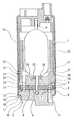
- FIG. 1shows a longitudinal section through a fuel pump according to the invention.
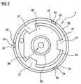
- FIG. 2shows a top view of an outlet-side casing part of the fuel pump from FIG. 1 .
- FIG. 1shows a longitudinal section through a fuel pump with a pump stage 2 driven by an electric motor 1 and designed as a side channel pump.
- the pump stage 2has an impeller arranged rotatably between two casing parts 3 , 4 .
- the impeller 5is arranged fixedly in terms of rotation on a shaft 6 of the electric motor 1 and has two rings, located opposite one another, of guide blades 8 delimiting blade chambers 7 .
- Part-annular ducts 9 , 10are arranged in each case, opposite the rings of the guide blades 8 , in the casing parts 3 , 4 .
- the part-annular ducts 9 , 10form with the blade chambers 7 a conveying chamber 13 leading from an inlet duct 11 to an outlet duct 12 .
- the inlet duct 11 and the outlet duct 12are arranged on casing parts 3 , 4 located opposite one another.
- the casing parts 3 , 4are spaced apart by means of a ring 14 .
- the fuel pumphas a jacket 15 made from sheet metal.
- the jacket 15is flanged at its ends and prestresses the components of the fuel pump with respect to one another.
- the inlet-side casing part 3consists essentially of a planar disk element 16 and of a rim 17 arranged at half the height of its circumference.
- the rim 17is consequently arranged level with the neutral fiber in terms of the buckling of the inlet-side casing part 3 and forms a force introduction point 18 for the jacket 15 .
- a flanging 19 of the jacket 15engages behind the rim 17 . Radial forces introduced from the flanging 19 into the rim 17 consequently do not lead to a flexion of the inlet-side casing part 3 .
- the outlet-side casing part 4has a disk element 20 located opposite the impeller 5 and, near its outer circumference, a rim 21 arranged perpendicularly with respect to the disk element 20 and in FIG. 2 is illustrated in a top view from the side of the electric motor 1 of FIG. 1 .
- a collar 22 running around radially outside the rim 21is led as far as the jacket 15 .
- a return ring 23 of the electric motor 1is supported axially on radially outer supporting elements 24 of the pump stage 2 which are arranged on the collar 22 .
- Force introduction points 25 for forces introduced axially into the outlet-side casing part 4are consequently arranged on the radially outer supporting elements 24 .
- Force introduction points 25 ′ for forces introduced radially into the outlet-side casing part 4are arranged on the rim near to the radially outer supporting elements 24 only.
- the outlet-side casing part 4has, as seen radially on the inside from the rim 21 , a groove 26 which is interrupted by radially inner supporting elements 27 connecting the rim 21 to the disk element 20 .
- the radially inner supporting elements 27are arranged so as to be offset with respect to the radially outer supporting elements 24 .
- Axial forces from the return ring 23 of the electric motor 1are introduced into the outlet-side casing part 4 via the radially outer supporting elements 24 and may lead to a deformation of the rim 21 .
- a transmission of the forces to the disk element 20is avoided by the arrangement of the radially inner and outer supporting elements 24 , 27 and the groove 26 in relation to one another.
- the forcescan be introduced only at the force introduction points 25 ′ for the radial forces.
- a countermomentis generated at the disk element 20 and prevents the flexion of the latter.
- the outlet-side casing part 3has an annular recess 28 in its radially inner region, as seen from the part-annular duct 10 .
- This annular recess 28decouples that region of the outlet-side casing part 4 which is located opposite the shaft 6 of the electric motor 1 from the region having the part-annular duct 10 .
- the outlet-side casing part 4has a mounting 29 for the shaft 6 of the electric motor 1 .
- the return ring 23 of the electric motor 1may also have individual supporting elements, by means of which it is supported between the radially inner supporting elements 27 of the outlet-side casing part 4 .
- the force introduction pointswould be arranged directly on the collar 22 running around.
Landscapes
- Engineering & Computer Science (AREA)
- Mechanical Engineering (AREA)
- General Engineering & Computer Science (AREA)
- Chemical & Material Sciences (AREA)
- Combustion & Propulsion (AREA)
- Structures Of Non-Positive Displacement Pumps (AREA)
- Fuel-Injection Apparatus (AREA)
Abstract
Description
Claims (12)
Applications Claiming Priority (4)
| Application Number | Priority Date | Filing Date | Title |
|---|---|---|---|
| DE10342256.0 | 2003-09-11 | ||
| DE10342256 | 2003-09-11 | ||
| DE10342256ADE10342256A1 (en) | 2003-09-11 | 2003-09-11 | Fuel pump |
| PCT/EP2004/051686WO2005026523A1 (en) | 2003-09-11 | 2004-08-02 | Fuel pump |
Publications (2)
| Publication Number | Publication Date |
|---|---|
| US20070065313A1 US20070065313A1 (en) | 2007-03-22 |
| US7862310B2true US7862310B2 (en) | 2011-01-04 |
Family
ID=34305708
Family Applications (1)
| Application Number | Title | Priority Date | Filing Date |
|---|---|---|---|
| US10/571,211Expired - Fee RelatedUS7862310B2 (en) | 2003-09-11 | 2004-08-02 | Fuel pump |
Country Status (6)
| Country | Link |
|---|---|
| US (1) | US7862310B2 (en) |
| EP (1) | EP1664521B1 (en) |
| JP (1) | JP4589324B2 (en) |
| CN (2) | CN101846017B (en) |
| DE (2) | DE10342256A1 (en) |
| WO (1) | WO2005026523A1 (en) |
Families Citing this family (3)
| Publication number | Priority date | Publication date | Assignee | Title |
|---|---|---|---|---|
| CA2806256A1 (en) | 2010-07-23 | 2012-01-26 | Tokai University Educational System | Oral medicinal composition for patients undergoing peritoneal dialysis and method for using same |
| CN102434339B (en)* | 2011-12-05 | 2015-10-14 | 遵义天义利威机电有限责任公司 | A kind of electric fuel pump of direct-current permanent magnet brushless car |
| DE102014106440A1 (en)* | 2014-05-08 | 2015-11-12 | Gebr. Becker Gmbh | Impeller, in particular for a side channel machine |
Citations (12)
| Publication number | Priority date | Publication date | Assignee | Title |
|---|---|---|---|---|
| DE3118533A1 (en) | 1981-05-09 | 1982-12-02 | Robert Bosch Gmbh, 7000 Stuttgart | Unit for delivering liquids |
| DE3130288A1 (en) | 1981-07-31 | 1983-02-17 | Robert Bosch Gmbh, 7000 Stuttgart | Fuel delivery unit having a pump rotor revolving in a pump chamber |
| DE3424520A1 (en) | 1984-07-04 | 1986-01-16 | SWF Auto-Electric GmbH, 7120 Bietigheim-Bissingen | FUEL DELIVERY PUMP |
| DE4240542A1 (en) | 1992-01-03 | 1993-07-08 | Walbro Corp | Centrifugal electrically driven fuel pump e.g for vehicle IC engine - has arcuate channel around rim of turbine-type wheel with pockets on both sides defined by circumferential rib |
| JPH06317285A (en) | 1993-02-09 | 1994-11-15 | Walbro Corp | Turbine blade fuel pump |
| US5702229A (en) | 1996-10-08 | 1997-12-30 | Walbro Corporation | Regenerative fuel pump |
| DE19900142A1 (en) | 1998-01-06 | 1999-07-08 | Walbro Corp | Fuel pump used in motor vehicle |
| JP2001115918A (en) | 1999-09-29 | 2001-04-27 | Visteon Global Technologies Inc | Fuel pump assembly |
| US6227819B1 (en) | 1999-03-29 | 2001-05-08 | Walbro Corporation | Fuel pumping assembly |
| US6231318B1 (en) | 1999-03-29 | 2001-05-15 | Walbro Corporation | In-take fuel pump reservoir |
| US6454521B1 (en) | 2000-11-15 | 2002-09-24 | Delphi Technologies, Inc. | Wear resistant fuel pump |
| US20030185693A1 (en)* | 2002-03-28 | 2003-10-02 | Eiji Iwanari | Fuel pump having brushes and method of manufacturing the same |
Family Cites Families (1)
| Publication number | Priority date | Publication date | Assignee | Title |
|---|---|---|---|---|
| CN2091370U (en)* | 1991-05-14 | 1991-12-25 | 王睢秦 | Fluoroplastic lining no-discharge pump |
- 2003
- 2003-09-11DEDE10342256Apatent/DE10342256A1/ennot_activeCeased
- 2004
- 2004-08-02WOPCT/EP2004/051686patent/WO2005026523A1/enactiveApplication Filing
- 2004-08-02EPEP04766393Apatent/EP1664521B1/ennot_activeExpired - Lifetime
- 2004-08-02CNCN2010101117103Apatent/CN101846017B/ennot_activeExpired - Fee Related
- 2004-08-02USUS10/571,211patent/US7862310B2/ennot_activeExpired - Fee Related
- 2004-08-02CNCN2004800261010Apatent/CN1849448B/ennot_activeExpired - Fee Related
- 2004-08-02JPJP2006523626Apatent/JP4589324B2/ennot_activeExpired - Fee Related
- 2004-08-02DEDE502004012152Tpatent/DE502004012152D1/ennot_activeExpired - Lifetime
Patent Citations (19)
| Publication number | Priority date | Publication date | Assignee | Title |
|---|---|---|---|---|
| DE3118533A1 (en) | 1981-05-09 | 1982-12-02 | Robert Bosch Gmbh, 7000 Stuttgart | Unit for delivering liquids |
| DE3130288A1 (en) | 1981-07-31 | 1983-02-17 | Robert Bosch Gmbh, 7000 Stuttgart | Fuel delivery unit having a pump rotor revolving in a pump chamber |
| DE3424520A1 (en) | 1984-07-04 | 1986-01-16 | SWF Auto-Electric GmbH, 7120 Bietigheim-Bissingen | FUEL DELIVERY PUMP |
| DE4240542A1 (en) | 1992-01-03 | 1993-07-08 | Walbro Corp | Centrifugal electrically driven fuel pump e.g for vehicle IC engine - has arcuate channel around rim of turbine-type wheel with pockets on both sides defined by circumferential rib |
| US5265997A (en) | 1992-01-03 | 1993-11-30 | Walbro Corporation | Turbine-vane fuel pump |
| JPH06317285A (en) | 1993-02-09 | 1994-11-15 | Walbro Corp | Turbine blade fuel pump |
| US5702229A (en) | 1996-10-08 | 1997-12-30 | Walbro Corporation | Regenerative fuel pump |
| DE19744753A1 (en) | 1996-10-08 | 1998-04-09 | Walbro Corp | Fuel pump |
| DE19900142A1 (en) | 1998-01-06 | 1999-07-08 | Walbro Corp | Fuel pump used in motor vehicle |
| JPH11257269A (en) | 1998-01-06 | 1999-09-21 | Walbro Corp | Pressure balancing type impeller fuel pump |
| US6019570A (en) | 1998-01-06 | 2000-02-01 | Walbro Corporation | Pressure balanced fuel pump impeller |
| US6227819B1 (en) | 1999-03-29 | 2001-05-08 | Walbro Corporation | Fuel pumping assembly |
| US6231318B1 (en) | 1999-03-29 | 2001-05-15 | Walbro Corporation | In-take fuel pump reservoir |
| JP2001115918A (en) | 1999-09-29 | 2001-04-27 | Visteon Global Technologies Inc | Fuel pump assembly |
| US6270310B1 (en) | 1999-09-29 | 2001-08-07 | Ford Global Tech., Inc. | Fuel pump assembly |
| DE10111990A1 (en) | 2000-03-17 | 2001-10-11 | Walbro Corp | Fuel pump assembly for engine, aligns exhaust port in housing of fuel pump module with tangential flow of fuel from exit passage of pumping channel so that fuel exits pumping channel relatively unimpeded |
| JP2001289190A (en) | 2000-03-17 | 2001-10-19 | Walbro Corp | Fuel pump assembly |
| US6454521B1 (en) | 2000-11-15 | 2002-09-24 | Delphi Technologies, Inc. | Wear resistant fuel pump |
| US20030185693A1 (en)* | 2002-03-28 | 2003-10-02 | Eiji Iwanari | Fuel pump having brushes and method of manufacturing the same |
Non-Patent Citations (1)
| Title |
|---|
| German language translation of Chinese Office Action dated Nov. 30, 2007 issued in corresponding Chinese application No. 200480026101.0. |
Also Published As
| Publication number | Publication date |
|---|---|
| WO2005026523A1 (en) | 2005-03-24 |
| DE10342256A1 (en) | 2005-04-28 |
| CN101846017B (en) | 2012-02-08 |
| CN101846017A (en) | 2010-09-29 |
| EP1664521A1 (en) | 2006-06-07 |
| DE502004012152D1 (en) | 2011-03-10 |
| JP2007502929A (en) | 2007-02-15 |
| CN1849448B (en) | 2010-06-16 |
| JP4589324B2 (en) | 2010-12-01 |
| CN1849448A (en) | 2006-10-18 |
| EP1664521B1 (en) | 2011-01-26 |
| US20070065313A1 (en) | 2007-03-22 |
Similar Documents
| Publication | Publication Date | Title |
|---|---|---|
| JP4468286B2 (en) | Exhaust turbocharger | |
| CN102282349A (en) | Connection assembly for joining a turbine housing and a bearing housing and exhaust gas turbocharger | |
| US5449269A (en) | Aggregate for feeding fuel from a supply tank to internal combustion engine of motor vehicle | |
| US6425734B2 (en) | Feed pump | |
| US6739832B2 (en) | Exhaust turbocharger | |
| US6832901B2 (en) | Aggregate for conveying fuel | |
| JP2003511596A (en) | Centrifugal pump | |
| US7862310B2 (en) | Fuel pump | |
| US20060153706A1 (en) | Internal gear-wheel pump comprising reinforced channels | |
| CN118574979A (en) | Turbine engine | |
| US6540474B2 (en) | Side-channel pump | |
| CN112840134A (en) | support assembly | |
| US6942446B2 (en) | Feed pump | |
| US8322978B2 (en) | Exhaust-driven turbocharger for a motor vehicle | |
| US20100021282A1 (en) | Side-Channel Pump | |
| US20190128140A1 (en) | Bearing device for an exhaust gas turbocharger, and exhaust gas turbocharger | |
| CN100482947C (en) | Fuel pump unit | |
| JP4580711B2 (en) | Electric motor fuel pump | |
| US8936452B2 (en) | Pump housing | |
| JPH10507244A (en) | Circumferential pumps, especially those that pump fuel from a vehicle storage tank to an internal combustion engine | |
| EP3708844B1 (en) | Turbocharger and bearing housing therefor | |
| US20210396175A1 (en) | Mid-frame section of a gas turbine engine and corresponding method of adjusting radial rotor clearance | |
| US7066711B2 (en) | Delivery pump | |
| US20100068046A1 (en) | Volute of lower end unit of fuel cell system | |
| US3314653A (en) | Unitary nozzles and shroud sections |
Legal Events
| Date | Code | Title | Description |
|---|---|---|---|
| AS | Assignment | Owner name:SIEMENS AKTIENGESELLSCHAFT, GERMANY Free format text:ASSIGNMENT OF ASSIGNORS INTEREST;ASSIGNORS:DEICHMANN, JOHANNES;GEISSEL, EBERHARD;KRETZSCHMAR, SVEN;AND OTHERS;SIGNING DATES FROM 20060120 TO 20060515;REEL/FRAME:018621/0285 Owner name:SIEMENS AKTIENGESELLSCHAFT, GERMANY Free format text:ASSIGNMENT OF ASSIGNORS INTEREST;ASSIGNORS:DEICHMANN, JOHANNES;GEISSEL, EBERHARD;KRETZSCHMAR, SVEN;AND OTHERS;REEL/FRAME:018621/0285;SIGNING DATES FROM 20060120 TO 20060515 | |
| FEPP | Fee payment procedure | Free format text:PAYOR NUMBER ASSIGNED (ORIGINAL EVENT CODE: ASPN); ENTITY STATUS OF PATENT OWNER: LARGE ENTITY | |
| STCF | Information on status: patent grant | Free format text:PATENTED CASE | |
| AS | Assignment | Owner name:CONTINENTAL AUTOMOTIVE GMBH, GERMANY Free format text:ASSIGNMENT OF ASSIGNORS INTEREST;ASSIGNOR:SIEMENS AKTIENGESELLSCHAFT;REEL/FRAME:027263/0068 Effective date:20110704 | |
| FPAY | Fee payment | Year of fee payment:4 | |
| MAFP | Maintenance fee payment | Free format text:PAYMENT OF MAINTENANCE FEE, 8TH YEAR, LARGE ENTITY (ORIGINAL EVENT CODE: M1552) Year of fee payment:8 | |
| FEPP | Fee payment procedure | Free format text:MAINTENANCE FEE REMINDER MAILED (ORIGINAL EVENT CODE: REM.); ENTITY STATUS OF PATENT OWNER: LARGE ENTITY | |
| LAPS | Lapse for failure to pay maintenance fees | Free format text:PATENT EXPIRED FOR FAILURE TO PAY MAINTENANCE FEES (ORIGINAL EVENT CODE: EXP.); ENTITY STATUS OF PATENT OWNER: LARGE ENTITY | |
| STCH | Information on status: patent discontinuation | Free format text:PATENT EXPIRED DUE TO NONPAYMENT OF MAINTENANCE FEES UNDER 37 CFR 1.362 | |
| FP | Lapsed due to failure to pay maintenance fee | Effective date:20230104 |