US7861762B2 - Overhead doors and associated track, guide, and bracket assemblies for use with same - Google Patents
Overhead doors and associated track, guide, and bracket assemblies for use with sameDownload PDFInfo
- Publication number
- US7861762B2 US7861762B2US12/191,146US19114608AUS7861762B2US 7861762 B2US7861762 B2US 7861762B2US 19114608 AUS19114608 AUS 19114608AUS 7861762 B2US7861762 B2US 7861762B2
- Authority
- US
- United States
- Prior art keywords
- guide
- door
- track segment
- gap region
- side portion
- Prior art date
- Legal status (The legal status is an assumption and is not a legal conclusion. Google has not performed a legal analysis and makes no representation as to the accuracy of the status listed.)
- Expired - Fee Related, expires
Links
Images


Classifications
- E—FIXED CONSTRUCTIONS
- E05—LOCKS; KEYS; WINDOW OR DOOR FITTINGS; SAFES
- E05D—HINGES OR SUSPENSION DEVICES FOR DOORS, WINDOWS OR WINGS
- E05D15/00—Suspension arrangements for wings
- E05D15/16—Suspension arrangements for wings for wings sliding vertically more or less in their own plane
- E05D15/24—Suspension arrangements for wings for wings sliding vertically more or less in their own plane consisting of parts connected at their edges
- E—FIXED CONSTRUCTIONS
- E05—LOCKS; KEYS; WINDOW OR DOOR FITTINGS; SAFES
- E05D—HINGES OR SUSPENSION DEVICES FOR DOORS, WINDOWS OR WINGS
- E05D15/00—Suspension arrangements for wings
- E05D15/16—Suspension arrangements for wings for wings sliding vertically more or less in their own plane
- E05D15/165—Details, e.g. sliding or rolling guides
- E—FIXED CONSTRUCTIONS
- E05—LOCKS; KEYS; WINDOW OR DOOR FITTINGS; SAFES
- E05Y—INDEXING SCHEME ASSOCIATED WITH SUBCLASSES E05D AND E05F, RELATING TO CONSTRUCTION ELEMENTS, ELECTRIC CONTROL, POWER SUPPLY, POWER SIGNAL OR TRANSMISSION, USER INTERFACES, MOUNTING OR COUPLING, DETAILS, ACCESSORIES, AUXILIARY OPERATIONS NOT OTHERWISE PROVIDED FOR, APPLICATION THEREOF
- E05Y2201/00—Constructional elements; Accessories therefor
- E05Y2201/60—Suspension or transmission members; Accessories therefor
- E05Y2201/606—Accessories therefor
- E05Y2201/61—Cooperation between suspension or transmission members
- E05Y2201/612—Cooperation between suspension or transmission members between carriers and rails
- E05Y2201/614—Anti-derailing means
- E—FIXED CONSTRUCTIONS
- E05—LOCKS; KEYS; WINDOW OR DOOR FITTINGS; SAFES
- E05Y—INDEXING SCHEME ASSOCIATED WITH SUBCLASSES E05D AND E05F, RELATING TO CONSTRUCTION ELEMENTS, ELECTRIC CONTROL, POWER SUPPLY, POWER SIGNAL OR TRANSMISSION, USER INTERFACES, MOUNTING OR COUPLING, DETAILS, ACCESSORIES, AUXILIARY OPERATIONS NOT OTHERWISE PROVIDED FOR, APPLICATION THEREOF
- E05Y2201/00—Constructional elements; Accessories therefor
- E05Y2201/60—Suspension or transmission members; Accessories therefor
- E05Y2201/622—Suspension or transmission members elements
- E05Y2201/684—Rails; Tracks
- E—FIXED CONSTRUCTIONS
- E05—LOCKS; KEYS; WINDOW OR DOOR FITTINGS; SAFES
- E05Y—INDEXING SCHEME ASSOCIATED WITH SUBCLASSES E05D AND E05F, RELATING TO CONSTRUCTION ELEMENTS, ELECTRIC CONTROL, POWER SUPPLY, POWER SIGNAL OR TRANSMISSION, USER INTERFACES, MOUNTING OR COUPLING, DETAILS, ACCESSORIES, AUXILIARY OPERATIONS NOT OTHERWISE PROVIDED FOR, APPLICATION THEREOF
- E05Y2900/00—Application of doors, windows, wings or fittings thereof
- E05Y2900/10—Application of doors, windows, wings or fittings thereof for buildings or parts thereof
- E05Y2900/106—Application of doors, windows, wings or fittings thereof for buildings or parts thereof for garages
Definitions
- the following disclosurerelates generally to overhead doors and, more particularly, to overhead door track, guide, and bracket assemblies.
- Overhead doorshave been used on loading docks and in various other warehouse and factory settings for many years.
- Conventional overhead doorsare of the sectional type, and typically include four or more rectangular panels hinged together along the upper and lower edges.
- Each of the door panelscarries two guide assemblies near the upper hinge line, and the bottom door panel carries two additional guide assemblies near the bottom edge.
- Each of the guide assembliestypically includes a plunger or roller device that extends outwardly from the door panel and is movably received in a channel section of an adjacent door track.
- the door tracksextend along the left and right sides of the door, and guide the door as it moves upwardly into the overhead or “open” position.
- Another problem with conventional overhead doorsis that they are susceptible to damage when used in factories, warehouses, and other commercial and industrial settings. Occasionally, for example, a forklift operator may inadvertently run into the door, as can happen when the door is in a partially open position. This can damage the door and/or the door tracks, making further use of the door difficult or impossible without time-consuming repairs.
- One way to overcome this problemis to equip the door with spring-loaded guide assemblies that retract and release from the tracks when struck with sufficient force in one or more directions, as disclosed in, for example, U.S. Pat. No. 5,535,805 to Kellog, et al., U.S. Pat. No. 5,927,368 to Rohrer, et al., U.S. Pat. No.
- An overhead door track assemblyconfigured in accordance with one aspect of the invention includes a vertical track segment mounted to a wall adjacent an opening therein, and a non-vertical track segment having a proximal end operably coupled to the vertical track segment and a distal end spaced apart from the wall.
- the non-vertical track segmentcan include a first side portion spaced apart from a second side portion to define a guide channel therebetween.
- the guide channelis configured to movably receive at least one door guide member as the door moves away from the opening toward the distal end of the non-vertical track segment.
- the track assemblyfurther includes a bracket, e.g., a “backhang” bracket, supporting the distal end of the non-vertical track segment.
- the bracketis fixedly attached to the first and second side portions of the non-vertical track segment and spans across at least a portion of the guide channel near the distal end of the non-vertical track segment.
- a door track assemblyconfigured in accordance with another aspect of the invention includes a vertical track segment, a curved track segment, and a non-vertical track segment.
- the vertical track segmentcan be mounted to a wall adjacent an opening therein.
- the curved track segmentcan be operably coupled to the vertical track segment, and can include a first guide surface spaced apart from a second guide surface to define a first gap region therebetween.
- the first gap regioncan be configured to movably receive at least one door guide member as the door moves away from the opening.
- the non-vertical track segmentcan include a proximal end operably coupled to the curved track segment and a distal end spaced apart from the wall.
- the non-vertical track segmentcan further include a third guide surface spaced apart from a fourth guide surface to define a second gap region therebetween.
- the second gap regioncan be wider than the first gap region to prevent or at least reduce binding of the at least one door guide member as the door moves from the curved track segment toward the distal end of the non-vertical track segment.
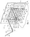
- FIG. 1is an isometric view of an overhead door assembly configured in accordance with an embodiment of the invention.
- FIG. 2is an enlarged, cross-sectional end view of a track section and guide assembly configured in accordance with an embodiment of the invention.
- FIG. 3is an enlarged, cross-sectional end view of a track section and guide assembly configured in accordance with another embodiment of the invention.
- FIG. 4is an enlarged side view of a portion of the door track assembly of FIG. 1 .
- FIG. 5is an enlarged, cross-sectional end view of a track section and two different door guide assemblies configured in accordance with further embodiments of the invention.
- FIGS. 6A and 6Bare enlarged, cross-sectional end views of a track section and two different door guide assemblies configured in accordance with additional embodiments of the invention.
- FIG. 7is a partially cut-away, enlarged isometric view of a portion of the door track assembly of FIG. 1 .
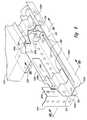
- FIG. 8is an enlarged isometric view of a distal end portion of the door track assembly of FIG. 1 , illustrating a track support bracket configured in accordance with an embodiment of the invention.
- FIGS. 9A and 9Bare enlarged, cross-sectional end views of the track section shown in FIG. 8 .
- FIG. 10Ais an isometric view of a distal end portion of a door track assembly, illustrating a track support bracket configured in accordance with another embodiment of the invention
- FIG. 10Bis an enlarged, cross-sectional end view of the track section shown in FIG. 10A .
- FIG. 11Ais an isometric view of a distal end portion of a door track assembly, illustrating a track support bracket configured in accordance with a further embodiment of the invention
- FIG. 11Bis an enlarged, cross-sectional end view of the track section shown in FIG. 11A .
- an overhead door trackhas a guide channel that widens as the track curves away from the door opening to prevent, or at least reduce door binding.
- a door track backhang bracketspans across the guide channel to act as a secondary door stop mechanism.
- FIG. 1is an isometric view of an overhead door assembly 110 configured in accordance with an embodiment of the invention.
- the overhead door assembly 110(“door assembly 110 ”) is installed in an opening 104 in a wall 102 of a building 100 .
- the wall 102can be part of a loading dock in a warehouse, factory, or other building 100 .
- the door assembly 110can be installed in other types of openings in other commercial and non-commercial buildings.
- the overhead door assembly 110includes a sectional door 120 that is movably supported in opposing track assemblies 112 (identified individually as a left or first track assembly 112 a and a right or second track assembly 112 b ).
- the sectional door 120includes a plurality of rectangular door panels 122 (identified individually as door panels 122 a - e ) which are pivotally attached to each other along hinge lines 123 (identified individually as hinge lines 123 a - d ).
- the first door panel 122 acarries a first interlocking guide assembly 124 a that movably engages the first track assembly 112 a , and a second interlocking guide assembly 124 b that movably engages the second track assembly 112 b .
- Each of the remaining door panels 122 b - ecarries a first releasable guide assembly 126 a that movably engages the first track assembly 112 a at least proximate to the upper hinge line 123 , and a second releasable guide assembly 126 b that movably engages the second track assembly 112 b at least proximate to the upper hinge line 123 .
- the fifth door panel 122 ecarries a third releasable guide assembly 126 c that movably engages the first track assembly 112 a at least proximate to a lower edge of the door panel 122 e , and a fourth releasable guide assembly 126 d that movably engages the second track assembly 112 b at least proximate to the lower edge of the door panel 122 e.
- overhead doorsconfigured in accordance with the present disclosure can include other guide assembly arrangements that differ from that illustrated in FIG. 1 .
- each of the door panels 122 a - dcan utilize the interlocking guide assemblies 124
- only the lowermost door panel 122 ecan utilize the releasable guide assemblies 126 .
- all of the door panels 122can utilize the interlocking guide assemblies 124 . Accordingly, the invention is not limited to the particular guide assembly configuration illustrated in FIG. 1 .
- the interlocking guide assemblies 124can include an “interlocking” guide member that is retained in the adjacent track section when subjected to a force in an outward or first direction 150 a or an inward or second direction 150 b .
- the releasable guide assemblies 126can include a “releasable” guide member that disengages from the adjacent track section (thereby allowing the corresponding door panel 122 to be “knocked-out”) when subjected to a sufficient force in one or both of the first direction 150 a and/or the second direction 150 b .
- each of the track assemblies 112includes a vertical track segment 113 secured to the wall 102 proximate the opening 104 , and a non-vertical track segment 115 which extends away from the wall 102 above the door opening 104 .
- a guard rail 140or a similar type of protective structure, can be installed around the lower portion of each of the vertical track segments 113 to protect it from damage from forklifts or other impacts.
- the distal end of each of the non-vertical track segments 115can be attached to an overhead support system 144 by a corresponding backhang bracket 142 (identified individually as a first backhang bracket 142 a and a second backhang bracket 142 b ).
- the support system 144can include a vertical member 144 a and a diagonal member 144 b having distal ends that are fixedly attached to adjacent building structures for support.
- a door bumper 145made of spring steel or other suitable material, can be fixedly attached near the distal end of each of the non-vertical track segments 115 to act as a primary door travel stop system and absorb the kinetic energy of the door 120 as it moves into the overhead position.
- Each of the track assemblies 112includes a plurality of multi-piece track sections 114 (identified individually as a first track section 114 a , a second track section 114 b , and a third track section 114 c ) operably coupled together in functional alignment at a first transition section 116 a and a second transition section 116 b .
- each of the track sections 114 a - chas a different cross-sectional shape that provides different door knock-out capabilities at different locations along the track.
- the cross-sectional shape of the first track section 114 aallows the releasable guide assemblies 126 to disengage from the track section 114 a when subjected to a force of a predetermined magnitude in the first direction 150 a .
- This same cross-sectional shapedoes not allow the releasable guide assemblies 126 to disengage from the first track section 114 a when subjected to a force in the opposite, second direction 150 b.
- this track sectionhas a cross-sectional shape that allows the releasable guide assemblies 126 to disengage when subjected to a force of sufficient magnitude in either the first direction 150 a or the second direction 150 b .
- the third track section 114 chas yet another cross-sectional shape that differs from both the first track section 114 a and the second track section 114 b .
- the third track section 114 chas a cross-sectional shape (or shapes) that retains both the releasable guide assemblies 126 and the interlocking guide assemblies 124 when the door 120 is in the overhead position, even when the door 120 is subjected to a substantial force in an upward or third direction 152 a or a downward or fourth direction 152 b .
- the overhead door assembly 110also includes a counterbalance system 130 fixedly attached to the building 100 above the door opening 104 .
- the counterbalance system 130can include a first cable 133 a and a second cable 133 b which are attached to the lower-most door panel 122 e .
- the counter balance cables 133may also be attached to other door panels 122 at the top or bottom.
- Each of the cables 133is operably coupled to a corresponding cable drum 138 (identified individually as a first cable drum 138 a and a second cable drum 138 b ).
- the cable drums 138are fixedly attached to an axle 132 which is rotatably supported by opposing bearing supports 134 a and 134 b .
- a first coil spring 136 a and a second coil spring 136 bare operably wound about the axle 132 , and exert a torsional force T 1 on the cable drums 138 which is proportional to the amount of cable extension.
- the torsional force T 1puts the cables 133 in tension, making it easier for a person to lift the door 120 and allowing the door 120 to close or lower at a controlled rate of speed
- the overhead door assembly 110can be equipped with an electric motor or other automated device for opening the door 120 . With the door 120 stowed in the overhead position, personnel can transport goods and materials through the opening 104 by forklift, dolly, or other conveyance.
- the door 120moves upwardly and then away from the wall 102 in a horizontal direction.
- an overhead doorconfigured in accordance with the present disclosure can move away from the opening 104 in multiple directions.
- the door 120can move along tracks that extend away from the wall 102 at any angle from about 0 degrees (i.e., parallel to the wall 102 ) to about 90 degrees (i.e., horizontal, as shown in FIG. 1 ). Accordingly, those of ordinary skill in the relevant art will appreciate that the present invention is not limited to the particular embodiment disclosed in FIG. 1 , but extends to other embodiments incorporating the inventive features disclosed herein.
- FIG. 2is an enlarged, cross-sectional end view taken along line 2 - 2 in FIG. 1 , showing the interlocking guide assembly 124 a movably engaged with the second track section 114 b in accordance with an embodiment of the invention.
- the second track section 114 bis formed from two separate side portions 210 (identified individually as a first side portion 210 a and a second side portion 210 b ) which are joined together along overlapping flanges 219 (identified individually as a first flange 219 a and a second flange 219 b ).
- the flanges 219can be joined together by a plurality of “clinched” connections formed by a process known as “clinching.”
- Clinchingis a method of joining two pieces of sheet metal by pressing them together with a die that forms a connection similar to a rivet.
- Hand operated clinching toolsare typically hydraulically driven, and make a connection by driving a punch into the die through overlapping material. When the material is forced to the bottom of the die, the material begins to mushroom and expands to allow full development of the connection. When the punch reaches its force limit, it is withdrawn. The result is a connection very similar to a riveted connection.
- the flanges 219can be joined together using a number of different techniques including, for example, fastening with rivets, screws, bolts, etc., bonding, welding, and/or other suitable methods known in the art.
- the first side portion 210 ais spaced apart from the second side portion 210 b to define a first gap region 212 therebetween.
- the first gap region 212has a first width or first gap dimension G 1 .
- the first side portion 210 aincludes a first guide surface 214 a and a first retention surface 216 a .
- the second side portion 210 bincludes a second guide surface 214 b and a second retention surface 216 b .
- first and second guide surfaces 214diverge from the first gap region 212 in a fifth direction 218 a to form a first “V-groove,” and the first and second retention surfaces 216 diverge from the first gap region 212 in a sixth direction 218 b , opposite to the fifth direction 218 a , to form a second “V-groove.” More specifically, in the illustrated embodiment, the first guide surface 214 a is disposed at a first angle 217 a of from about 60 degrees to about 120 degrees, e.g., about 90 degrees relative to the second guide surface 214 b .
- the first retention surface 216 acan be disposed at a second angle 217 b of from about 40 degrees to about 180 degrees relative to the second retention surface 216 b .
- the first retention surface 216 acan be disposed at a second angle 217 b of from about 60 degrees to about 160 degrees, e.g., about 120 degrees relative to the second retention surface 216 b .
- the first and second guide surfaces 214 , and/or the first and second retention surfaces 216can be disposed at other angles, or be parallel, relative to each other.
- the second track section 114 bfurther includes a seal surface 211 extending from the first guide surface 214 a .
- the first door panel 122 acarries a compressible door seal 226 that slideably contacts the seal surface 211 .
- the door seal 226can be manufactured from rubber, polyurethane, foam, and/or any other suitable material known in the art.
- the side portions 210can be formed with a brake press from a suitable sheet metal, such as galvanized steel having a thickness ranging from about 10 gauge to about 20 gauge, e.g. about 16 gauge.
- the side portions 210can be roll- or press-formed from a suitable sheet metal.
- One advantage of making the track sections 114 from two (or more) pieces of formed sheet metalis that the individual side portions 210 have shapes that are relatively easy to form by conventional brake- and roll-forming methods.
- the side portions 210 , and/or other overhead door track components embodying the inventive features disclosed hereincan be machined, cast, or otherwise formed from other metallic and non-metallic materials having suitable strength, stiffness, forming, cost, and/or other characteristics. Accordingly, those of ordinary skill in the art will appreciate that aspects of the present invention are not limited to the particular manufacturing methods disclosed herein.
- the interlocking guide assembly 124 aincludes an interlocking guide member 250 that projects outwardly from a door edge region 228 a distance D 1 along a longitudinal axis 251 of the guide member 250 .
- the interlocking guide member 250includes a cylindrical shaft 253 having a first shaft portion 256 a and a smaller-diameter second shaft portion 256 b .
- the first shaft portion 256 aextends through a first aperture 257 a in a first journal 258 a .
- the second shaft portion 256 bextends from the first shaft portion 256 a through a coaxial second aperture 257 b in a second journal 258 b .
- the journals 258are carried by a bracket 259 which is fixedly attached to the first door panel 122 a by a plurality of bolts 224 or other suitable fasteners and/or methods known in the art.
- the distal end of the first shaft portion 256 acarries an enlarged head portion 254 that is movably retained by the retention surfaces 216 of the second track section 114 b .
- the enlarged head portion 254flares outwardly from the first shaft portion 256 a to form a reverse conical, or at least generally conical, surface 255 .
- the angle of the surface 255is at least generally similar, or at least approximately parallel, to the angle 217 b between the adjacent retention surfaces 216 .
- the first shaft portion 256 acan have a diameter of from about 0.25 inch to about 0.75 inch, e.g., about 0.50 inch, and the first gap dimension G 1 can be from about 0.375 inch to about 0.875 inch, e.g., about 0.625 inch to provide sufficient clearance for the first shaft portion 256 a while still retaining the enlarged head portion 254 .
- the first gap dimension G 1can be from about 0.375 inch to about 0.875 inch, e.g., about 0.625 inch to provide sufficient clearance for the first shaft portion 256 a while still retaining the enlarged head portion 254 .
- other configurations of interlocking guide members and associated track sectionscan be employed without departing from the spirit or scope of the present disclosure.
- the enlarged head portion 254can have other shapes, such as spherical shapes, cylindrical shapes, etc., and the adjacent track surfaces can have other shapes that may or may not reflect the shape of the enlarged head portion.
- interlocking guide memberscan include rollers or similar devices attached to the distal end of the first shaft portion 256 a to function as the enlarged head portion 254 .
- the present inventionis not limited to the particular interlocking guide assembly illustrated in FIG. 2 , but extends to other embodiments incorporating the various features disclosed herein.
- the second shaft portion 256 bcarries first and second coil springs 260 a, b which are compressed against opposite sides of the second journal 258 b and held in place by washers 264 and associated pins 262 .
- the coil springs 260permit the guide member 250 to move back and forth along the longitudinal axis 251 a preset distance, such as from about 0.1 inch to about 0.5 inch, e.g., about 0.25 inch. This movement enables the guide member 250 to accommodate minor misalignments of the track section 114 b without binding.
- a track bracket 270fixedly attaches the second track section 114 b to the wall 102 .
- the track bracket 270can include a mounting flange 272 through which one or more fasteners 274 extend to attach the track bracket 270 to the wall 102 .
- FIG. 3is an enlarged, cross-sectional end view taken along line 3 - 3 in FIG. 1 , illustrating engagement of the releasable guide assembly 126 a with the second track section 114 b .
- the various track section and door panel features described above with reference to FIG. 2apply to FIG. 3 as well.
- the releasable guide assembly 126 aincludes a releasable guide member 350 that lacks the enlarged head portion 254 of the interlocking guide member 250 described above.
- the releasable guide member 350projects outwardly from the door edge region 228 along a longitudinal axis 351 , and includes a cylindrical shaft 353 having a first shaft portion 356 a and a smaller-diameter second shaft portion 356 b .
- the first shaft portion 356 aslidably extends through a first aperture 357 a in a first journal 358 a .
- the second shaft portion 356 bextends from the first shaft portion 356 a through a coaxial second aperture 357 b in a second journal 358 b .
- the second shaft portion 356 bpasses through a coil spring 360 that is compressed between the second journal 358 b and a washer 364 which is held in place by a pin 362 .
- the washer 364 and the pin 362can be replaced by an E-ring or other suitable retainer.
- the first shaft portion 356 ahas a constant, or at least approximately constant, diameter S until it reaches a hemispherical, or at least approximately hemispherical head portion 354 .
- the diameter Scan be from about 0.50 inch to about 1.0 inch, e.g., about 0.75 inch.
- the first gap dimension G 1is smaller than the diameter S (e.g., the first gap dimension G 1 can be about 0.625 inch) to prevent interference of the head portion 354 with the first gap region 212 during door operation. If this were to happen, it could impede the knock-out capability of the releasable guide member 350 .
- the first shaft portion 356 a , or parts thereof,can be made from a suitable polymer material, such as plastic, Delrin®, Teflon®, etc. to reduce friction between it and the track section 114 b.
- the coil spring 360urges the first shaft portion 356 a outwardly in the sixth direction 218 b toward the second track section 114 b .
- An E-ring or other type of retainer 359is fixedly attached to the second shaft portion 356 b , however, to prevent the head portion 354 from projecting beyond a distance D 2 from the edge region 228 of the door panel 122 c .
- the distance D 2is less than the distance D 1 discussed above with reference to FIG. 2 .
- the coil spring 360allows the head portion 354 to move inwardly in the fifth direction 218 a a preset distance, such as from about 0.5 inches to about 1.5 inches, e.g., about 1.25 inches.
- the releasable guide member 350allows the third door panel 122 c to be disengaged or “knocked-out” of the second track section 114 b when a force of sufficient magnitude is exerted against the door panel 122 c in the outward or first direction 150 a or the inward or second direction 150 b .
- a force of sufficient magnitudeis exerted against the door panel 122 c in the outward or first direction 150 a or the inward or second direction 150 b .
- the forcecauses the rounded head portion 354 of the guide member 350 to bear against the first guide surface 214 a .
- the angle of the guide surface 214 acauses the guide member 350 to retract inwardly in the fifth direction 218 a as the door panel 122 c continues moving outwardly in the first direction 150 a .
- the releasable guide assembly 126 acan further include a D-ring or other type of pull feature 363 for manually retracting the releasable guide member 350 if desired to facilitate door panel installation, reinstallation, or removal.
- FIG. 4is an enlarged side view of a portion of the first track assembly 112 a of FIG. 1 , configured in accordance with an embodiment of the invention.
- the first track assembly 112 aincludes a first curved track segment 402 a and a first non-vertical track segment 404 a .
- the non-vertical track segment 404 aincludes a first track brace 408 a which extends toward the wall 102 of the building 100 ( FIG. 1 ).
- the curved track segment 402 aincludes a second gap region 412 a having a second gap dimension G 2 .
- the non-vertical track segment 404 aincludes the third gap region 412 b and a fourth gap region 412 c .
- the third gap region 412 bhas a third gap dimension G 3
- the fourth gap region 412 chas a fourth gap dimension G 4
- the track assembly 112 afurther includes a transition section 406 to accommodate the step up from the second gap region 412 a of the curved track segment 402 a to the fourth gap region 412 c of the non-vertical track segment 404 a.
- the second gap region 412 a in the curved track segment 402 amovably receives the interlocking guide member 250 and the releasable guide member 350 ( FIGS. 2 and 3 , respectively) as the door 120 moves away from the opening 104 ( FIG. 1 ).
- the third gap region 412 breceives the interlocking guide member 250 .
- the releasable guide member 350is free to move within the wider fourth gap region 412 c .
- the increased width of the fourth gap region 412 cenables the door panels 122 ( FIG. 1 ) to move into the overhead position without binding.
- FIG. 5is an enlarged, cross-sectional end view taken along line 5 - 5 in FIG. 4 .
- This viewillustrates the interlocking guide member 250 and the releasable guide member 350 (shown in phantom line) movably received in the second gap region 412 a of the curved track segment 402 a .
- the second gap region 412 adefines a guide channel that extends between a third side portion 510 a and a fourth side portion 510 b .
- the third side portion 510 aincludes a third guide surface 514 a and a third retention surface 516 a .
- the fourth side portion 510 bincludes a fourth guide surface 514 b and a fourth retention surface 516 b .
- the guide surfaces 514extend parallel, or at least approximately parallel, to the longitudinal axis 351 of the releasable guide member 350 ( FIG. 3 ) to prevent the releasable guide member 350 from being knocked out of the curved track segment 402 during door operation.
- the retention surfaces 516are at least generally similar in structure and function to the retention surfaces 216 described above with reference to FIG. 2 .
- the second gap dimension G 2can be slightly larger than the first gap dimension G 1 shown in FIGS. 2 and 3 , to reduce skidding and/or scuffing of the releasable guide member 350 and the interlocking guide member 250 as they move through the second gap region 412 a .
- the second gap dimension G 2can be from about 0.625 inch to about 1.125 inches, e.g., about 0.875 inch. In other embodiments, however, the second gap region 412 a can have other dimensions.
- FIGS. 6A and 6Bare enlarged, cross-sectional end views taken along line 6 - 6 in FIG. 4 . More specifically, FIG. 6A shows the interlocking guide member 250 movably engaged with the non-vertical track segment 404 a , and FIG. 6B shows the releasable guide member 350 movably engaged with the non-vertical track segment 404 a .
- the non-vertical track segment 404 aincludes a fifth side portion 610 a spaced apart from a sixth side portion 610 b .
- the fifth side portion 610 aincludes a fifth guide surface 614 a and a fifth retention surface 616 a .
- the sixth side portion 610 bincludes a sixth guide surface 614 b and a sixth retention surface 616 b .
- the fifth retention surface 616 ais at least approximately aligned with the third retention surface 516 a ( FIG. 5 )
- the sixth retention surface 616 bis at least approximately aligned with the fourth retention surface 516 b
- the sixth guide surface 614 bis at least approximately aligned with the fourth guide surface 514 b.
- the third gap region 412 bextends between the sixth side portion 610 b and a first upper track rail 620 a that is fastened or otherwise attached to the track brace 408 a .
- the upper track rail 620 acan be fastened to the track brace 408 a by a plurality of mechanically “clinched” connections 680 , or by other suitable fastening techniques known in the art.
- the fourth gap region 412 cextends between the fifth guide surface 614 a and the sixth guide surface 614 b .
- the guide surfaces 614extend at least approximately parallel to the longitudinal axis 251 of the interlocking guide member 250 .
- the interlocking guide member 250moves back and forth in the third gap region 412 b , but is held in the non-vertical track segment 404 a by the retention surfaces 616 .
- the releasable guide member 350not only moves back and forth, but it can also move up and down in the fourth gap region 412 c because of the enlarged fourth gap dimension G 4 . This freedom of movement can alleviate binding as the door moves from the curved track segment 402 a ( FIG. 4 ) to the non-vertical track segment 404 a .
- the guide channel of the present inventionenables doors to move smoothly through curved track segments by providing additional clearance for the releasable guide members 350 .
- the third gap dimension G 3can be slightly smaller than the second gap dimension G 2 shown in FIG. 5 , to prevent the releasable guide member 350 from extending through the third gap region 412 b during normal door operation.
- the third gap dimension G 3can be from about 0.375 inch to about 0.875 inch, e.g., about 0.625 inch. In other embodiments, however, the third gap region 412 b can have other dimensions
- FIG. 7is an enlarged, partially cut-away isometric view of a portion of the second track assembly 112 b of FIG. 1 .
- the second door bumper 145 b of FIG. 1has been omitted from FIG. 7 for purposes of clarity.
- the second track assembly 112 bis, in general at least, a mirror image of the first track assembly 112 a described in detail above. Accordingly, the second track assembly 112 b is at least generally similar in structure and function to the first track assembly 112 a .
- the second track assembly 112 bincludes a second curved track segment 402 b operably connected to a second non-vertical track segment 404 b .
- the non-vertical track segment 404 bincludes a second track brace 408 b which is attached to the wall 102 ( FIG. 1 ).
- the non-vertical track segment 404 bincludes a seventh side portion 610 c spaced apart from an eighth side portion 610 d .
- the seventh side portion 610 cis formed by a second upper track rail 620 b that is fastened or otherwise attached to the second track brace 408 b.
- FIG. 8is an enlarged isometric view of the distal end portion of the second track assembly 112 b of FIG. 7 , showing various features of the second backhang bracket 142 b in more detail.
- the backhang bracket 142 bincludes an upstanding flange 854 extending from a base flange 852 .
- the base flange 852is fixedly attached to the eighth side portion 610 d of the non-vertical track segment 404 b with a plurality of clinched connections or other suitable fasteners 880 .
- the upstanding flange 854includes a first tab 856 a positioned toward a leading edge 850 a , and a second tab 856 b positioned toward a trailing edge 850 b .
- the tabs 856are fixedly attached to an upper flange portion of the second track brace 408 b.
- the upper track rail 620 bdoes not extend to the distal end of the non-vertical track segment 404 b , but instead has an end edge 830 that is positioned just short of the leading edge 850 a of the backhang bracket 142 b . Truncating the upper track rail 620 b at this location enables a technician or other service personnel to remove the interlocking guide member 250 from the non-vertical track segment 404 b if needed for maintenance, repairs, replacement, etc. This can be accomplished by first detaching the bracket 259 from the door panel 122 a , rotating the guide member 250 as shown by the dotted lines in FIG. 8 , and then extracting the guide member 250 from the non-vertical track segment 404 b .
- An access aperture 858 in the backhang bracket 142 bmay provide access to one or more of the fasteners (not shown) that attach the door bumper 145 b ( FIG. 1 ) to the backhang bracket 142 b.
- FIGS. 9A and 9Bare enlarged, cross-sectional end views taken along lines 9 A- 9 A and 9 B- 9 B in FIG. 8 , respectively.
- These figuresillustrate how the backhang bracket 142 b can function as a secondary door stop system.
- the door bumpers 145FIG. 1
- the door 120may continue moving aft on the non-vertical track segments 404 when the door 120 is lifted to the overhead position.
- the interlocking guide members 250will run into the leading edges 850 a ( FIG. 8 ) of the corresponding backhang brackets 142 , as shown in FIGS. 9A and 9B .
- a further feature of the backhang bracket assembly illustrated in FIG. 9Bis that the upper track rail 620 b does not extend to the distal end of the non-vertical track segment 404 b.
- FIG. 10Ais an enlarged, partially cut-away isometric view of a distal end portion of a non-vertical track segment 1004 having a backhang bracket 1042 configured in accordance with another embodiment of the invention.
- FIG. 10Bis a cross-sectional end view taken along line 10 B- 10 B in FIG. 10A .
- the backhang bracket 1042includes an upstanding flange 1054 that extends from a base flange 1052 .
- the upstanding flange 1054includes a joggle 1060 that positions the upstanding flange 1054 in contact with the track brace 408 b so that the upstanding flange 1054 can be fastened to the track brace 408 b with a plurality of clinched connections or other suitable fasteners 1080 .
- FIG. 11Ais an enlarged, partially cut-away isometric view of a distal end portion of a non-vertical track segment 1104 configured in accordance with yet another embodiment of the invention
- FIG. 11Bis a cross-sectional end view taken along line 11 B- 11 B in FIG. 11A .
- many features of the non-vertical track segment 1104are at least generally similar in structure and function to the corresponding features of the non-vertical track segments 404 and 1004 described above.
- the non-vertical track segment 1104includes a backhang bracket 1142 which is fixedly attached to the track brace 408 b and the eighth side portion 610 d .
- the backhang bracket 1142is a subassembly of sheet metal parts having an upstanding flange 1154 with an offset portion 1156 , and two base flanges 1152 (identified individually as a first base flange 1152 a and a second base flange 1152 b ).
- the two base flanges 1152provide additional strength and stability to the backhang bracket assembly, while the offset portion 1156 provides an offset surface for fastening the backhang bracket 1142 to the track brace 408 b.
- FIGS. 8-11Billustrate, there are a number of different backhang bracket configurations consistent with the present disclosure for stabilizing and strengthening non-vertical overhead door track segments, while also acting as secondary door travel stop systems. Accordingly, those of ordinary skill in the art will appreciate that the present invention is not limited to the particular backhang bracket configurations described above, but extends to multiple other configurations embodying the inventive features set forth in the following claims.
Landscapes
- Engineering & Computer Science (AREA)
- Mechanical Engineering (AREA)
- Operating, Guiding And Securing Of Roll- Type Closing Members (AREA)
- Wing Frames And Configurations (AREA)
Abstract
Description
Claims (18)
Priority Applications (1)
| Application Number | Priority Date | Filing Date | Title |
|---|---|---|---|
| US12/191,146US7861762B2 (en) | 2007-08-16 | 2008-08-13 | Overhead doors and associated track, guide, and bracket assemblies for use with same |
Applications Claiming Priority (4)
| Application Number | Priority Date | Filing Date | Title |
|---|---|---|---|
| US95635507P | 2007-08-16 | 2007-08-16 | |
| US95636307P | 2007-08-16 | 2007-08-16 | |
| US95636807P | 2007-08-16 | 2007-08-16 | |
| US12/191,146US7861762B2 (en) | 2007-08-16 | 2008-08-13 | Overhead doors and associated track, guide, and bracket assemblies for use with same |
Publications (2)
| Publication Number | Publication Date |
|---|---|
| US20090044917A1 US20090044917A1 (en) | 2009-02-19 |
| US7861762B2true US7861762B2 (en) | 2011-01-04 |
Family
ID=40361855
Family Applications (4)
| Application Number | Title | Priority Date | Filing Date |
|---|---|---|---|
| US12/191,140Expired - Fee RelatedUS8037576B2 (en) | 2007-08-16 | 2008-08-13 | Overhead doors and associated track and guide assemblies for use with same |
| US12/191,118Expired - Fee RelatedUS7891400B2 (en) | 2007-08-16 | 2008-08-13 | Overhead doors and associated track and guide assemblies for use with same |
| US12/191,146Expired - Fee RelatedUS7861762B2 (en) | 2007-08-16 | 2008-08-13 | Overhead doors and associated track, guide, and bracket assemblies for use with same |
| US12/976,807Expired - Fee RelatedUS8297333B2 (en) | 2007-08-16 | 2010-12-22 | Overhead doors and associated track and guide assemblies for use with same |
Family Applications Before (2)
| Application Number | Title | Priority Date | Filing Date |
|---|---|---|---|
| US12/191,140Expired - Fee RelatedUS8037576B2 (en) | 2007-08-16 | 2008-08-13 | Overhead doors and associated track and guide assemblies for use with same |
| US12/191,118Expired - Fee RelatedUS7891400B2 (en) | 2007-08-16 | 2008-08-13 | Overhead doors and associated track and guide assemblies for use with same |
Family Applications After (1)
| Application Number | Title | Priority Date | Filing Date |
|---|---|---|---|
| US12/976,807Expired - Fee RelatedUS8297333B2 (en) | 2007-08-16 | 2010-12-22 | Overhead doors and associated track and guide assemblies for use with same |
Country Status (1)
| Country | Link |
|---|---|
| US (4) | US8037576B2 (en) |
Cited By (13)
| Publication number | Priority date | Publication date | Assignee | Title |
|---|---|---|---|---|
| US20100088965A1 (en)* | 2006-10-06 | 2010-04-15 | Dl Manufacturing | Overhead door with dual track mounting |
| US20100212227A1 (en)* | 2009-02-26 | 2010-08-26 | Perkins Mark R | Physical security barrier |
| US8307589B2 (en) | 2008-12-12 | 2012-11-13 | 4Front Engineered Solutions, Inc. | Segmented dock seals for truck loading docks and associated systems and methods |
| US20130056995A1 (en)* | 2011-09-01 | 2013-03-07 | Jamas Enterprises LLC. | Sliding Pin Lock Mechanism for Overhead Door |
| US8893764B2 (en) | 2012-08-08 | 2014-11-25 | 4Front Engineered Solutions, Inc. | Overhead door decelerators and associated devices, systems, and methods |
| US20170183897A1 (en)* | 2015-11-19 | 2017-06-29 | Daryl W. Bruckelmyer | Overhead Garage Door System With Sealing Feature |
| US20180279818A1 (en)* | 2016-08-31 | 2018-10-04 | Karen Goelst | Retrofit Curtain Assembly |
| US11317753B1 (en) | 2021-02-04 | 2022-05-03 | Kleenedge, Llc | Partition curtain track system |
| US20230160248A1 (en)* | 2021-04-29 | 2023-05-25 | Dennis Palmer | Sealing assembly for multi-panel doors |
| US20230374836A1 (en)* | 2022-05-23 | 2023-11-23 | Cornellcookson, Llc | Vertically stacking panel door with improved curved track portions |
| US12240716B2 (en) | 2022-08-17 | 2025-03-04 | Assa Abloy Entrance Systems Ab | Wiper seal pad systems |
| US12264523B2 (en) | 2020-11-30 | 2025-04-01 | Daryl W. Bruckelmyer | Overhead garage door system with sealing feature |
| US20250137308A1 (en)* | 2023-10-31 | 2025-05-01 | Overhead Door Corporation | Anchor system with integrated cable pin |
Families Citing this family (22)
| Publication number | Priority date | Publication date | Assignee | Title |
|---|---|---|---|---|
| US7784520B2 (en)* | 2006-06-16 | 2010-08-31 | Rick Paulson | Garage mechanism protector |
| US8037576B2 (en) | 2007-08-16 | 2011-10-18 | 4Front Engineered Solutions, Inc. | Overhead doors and associated track and guide assemblies for use with same |
| US20090077906A1 (en)* | 2007-09-24 | 2009-03-26 | 4Front Engineered Solutions, Inc. | Loading dock truck shelters |
| US8181401B2 (en)* | 2009-01-26 | 2012-05-22 | 4Front Engineered Solutions, Inc. | Loading dock truck and trailer seals and associated systems and methods |
| US8056174B2 (en)* | 2009-09-14 | 2011-11-15 | Midwest Industrial Door, Inc. | Repositionable pit seal |
| US9004144B2 (en)* | 2009-09-18 | 2015-04-14 | Matthew S. Douglas | Window covering with independently movable support rods |
| US8959838B1 (en) | 2009-12-18 | 2015-02-24 | Vittorio Marinelli | Cargo vehicle security system and method of use |
| US8438784B1 (en)* | 2009-12-19 | 2013-05-14 | Vittorio Marinelli | Automated vehicle cargo door opener |
| JP5646934B2 (en)* | 2010-09-24 | 2014-12-24 | 芦森工業株式会社 | Sunshade equipment |
| US8510888B2 (en) | 2012-01-03 | 2013-08-20 | 4Front Engineered Solutions, Inc. | Dock leveler sealing systems |
| US9127501B1 (en)* | 2012-01-10 | 2015-09-08 | Stoebich Brandschutz Gmbh | Lead system for a fire and smoke protection device |
| US9303683B1 (en)* | 2012-05-26 | 2016-04-05 | Leonard Ray Newcomb, Jr. | Detachable connector system for multi-panel structure |
| US8887442B2 (en)* | 2012-10-04 | 2014-11-18 | Cold Chain, Llc | System for allowing a loading dock door to release from a track |
| US9045924B2 (en) | 2012-10-04 | 2015-06-02 | Cold Chain, Llc | Breakaway loading dock door system |
| CN103437697A (en)* | 2013-09-09 | 2013-12-11 | 伟攀(上海)安全防护设备有限公司 | Giant whole floating hangar door |
| US9624708B2 (en)* | 2015-03-10 | 2017-04-18 | Ciw Enterprises, Inc. | Closure with roller endlock |
| US20190145156A1 (en)* | 2016-06-01 | 2019-05-16 | Centurion Garage Doors Pty Ltd | Bracing Member, Coupling and System for a Sectional Door |
| US11351277B2 (en)* | 2017-06-27 | 2022-06-07 | American Sterilizer Company | Self-adjusting damper based linear alignment system |
| CA3077055A1 (en) | 2017-09-28 | 2019-04-04 | Cornellcookson, Llc | Slip fit guide |
| US10494205B1 (en) | 2018-12-06 | 2019-12-03 | Assa Abloy Entrance Systems Ab | Remote loading dock authorization systems and methods |
| US11713606B2 (en)* | 2020-02-14 | 2023-08-01 | Engineered Hardware, Llc | Direct drive counter balancing system for overhead doors |
| US11655659B2 (en)* | 2020-06-10 | 2023-05-23 | Daniel Deutsch | Quick release door roller assembly |
Citations (122)
| Publication number | Priority date | Publication date | Assignee | Title |
|---|---|---|---|---|
| US1787451A (en) | 1929-12-09 | 1931-01-06 | Nat Lock Washer Co | Curtain fixture |
| US1990870A (en)* | 1931-03-26 | 1935-02-12 | Harry G Kelly | Rolling door mechanism |
| US2064470A (en) | 1931-01-17 | 1936-12-15 | Richards Wilcox Mfg Co | Overhead door |
| US2090146A (en) | 1931-11-06 | 1937-08-17 | Nat Mfg Co | Closure |
| US2124969A (en) | 1936-03-25 | 1938-07-26 | Huck Gerhardt Company Inc | Overhead garage door construction |
| US2686926A (en) | 1953-03-02 | 1954-08-24 | Overhead Door Corp | Track for upwardly acting doors |
| US2839135A (en) | 1956-02-16 | 1958-06-17 | Kinnear Mfg Co | Rolling door |
| US3140508A (en) | 1962-02-15 | 1964-07-14 | Ridge Nassau Corp | Overhead door hardware |
| US3188698A (en) | 1960-12-01 | 1965-06-15 | Wilson J G Corp | Safety device for vertically movable doors |
| US3336968A (en) | 1965-03-29 | 1967-08-22 | Guy A Curtis | Garage door with anti-jamming rollers |
| US3484812A (en) | 1968-11-01 | 1969-12-16 | Frantz Mfg Co | Means for limiting axial movement in a hinge hanger assembly |
| US3552474A (en) | 1969-02-17 | 1971-01-05 | John E Finnegan | Diamond roller |
| US3693693A (en) | 1970-12-11 | 1972-09-26 | Charles T Court | Vertically sliding door mounted in horizontally pivoted frame |
| US3934635A (en) | 1972-10-17 | 1976-01-27 | Krs Industries, Inc. | Overhead door for a container having a vertical opening such as a truck trailer |
| US4016920A (en) | 1975-05-23 | 1977-04-12 | United States Steel Corporation | Flexible guiding track and release mechanism for an overhead rolling door assembly |
| US4080757A (en) | 1976-09-20 | 1978-03-28 | Floyd Westerman | Door latch |
| US4120072A (en) | 1976-08-26 | 1978-10-17 | Hormann Kg Amshausen | Combined supporting roller-friction drive arrangement for overhead single-panel doors |
| US4155268A (en) | 1977-09-16 | 1979-05-22 | Clopay Corporation | Traveler apparatus for screw drive closure operator |
| US4205713A (en) | 1978-05-22 | 1980-06-03 | Overhead Door Corporation | Hinge and roller |
| US4352585A (en) | 1980-03-06 | 1982-10-05 | The Alliance Manufacturing Company, Inc. | Door operator screw coupling |
| US4379479A (en) | 1982-06-01 | 1983-04-12 | Whiting Roll-Up Door Mfg. Corp. | Roller assembly |
| US4478268A (en) | 1980-12-29 | 1984-10-23 | Copper Cliff Door Manufacturing (1980) Limited | Door structure |
| US4572268A (en) | 1983-04-28 | 1986-02-25 | Uneek Cap And Coor, Inc. | Roller and track means for an overhead door |
| US4601320A (en) | 1984-02-09 | 1986-07-22 | Douglas Taylor | Industrial door |
| US4676293A (en) | 1983-03-18 | 1987-06-30 | Frommelt Industries, Inc. | Impact-resistant overhead door |
| US4800618A (en) | 1987-10-01 | 1989-01-31 | Putz Helmut J | Overhead garage door selfsealing device |
| US4836589A (en) | 1986-12-18 | 1989-06-06 | Mohr Russel R | Door lock |
| US4846245A (en) | 1987-08-27 | 1989-07-11 | Alto Garage Door | Folding door apparatus |
| US4934835A (en) | 1988-05-06 | 1990-06-19 | Deutsche Star Gmbh | Linear guidance unit |
| US5036899A (en) | 1990-08-02 | 1991-08-06 | Mullet Willis J | Panel garage door opening and closing |
| US5131450A (en) | 1990-06-08 | 1992-07-21 | Dale Lichy | Closure assembly for structural members |
| US5141043A (en) | 1989-05-19 | 1992-08-25 | Nergeco Sa | Lifting curtain door |
| US5163495A (en) | 1990-06-08 | 1992-11-17 | Dale Lichy | Closure assembly for structural members |
| US5219015A (en) | 1989-05-19 | 1993-06-15 | Nergeco Sa | Lifting curtain door |
| US5222541A (en) | 1992-07-22 | 1993-06-29 | Kelley Company, Inc. | Industrial door having releasable beam and tension bracket retention mechanism |
| US5240216A (en) | 1991-05-24 | 1993-08-31 | Clopay Corporation | Universal angled flag bracket for use with tracks for sectional overhead doors |
| US5271448A (en) | 1992-07-27 | 1993-12-21 | Rytec Corporation | Movable barrier with two part guide follower |
| US5291686A (en) | 1992-12-07 | 1994-03-08 | Russ Sears | Overhead door safety apparatus |
| US5299617A (en) | 1991-01-25 | 1994-04-05 | Asi Technologies, Inc. | Breakaway roll-up door |
| US5307855A (en) | 1992-10-02 | 1994-05-03 | Awnings Unlimited, Inc. | Tape drive extendable and retractable awning assembly |
| US5353473A (en) | 1993-04-12 | 1994-10-11 | Sherick Thomas G | Bottom fixture for overhead garage doors |
| US5353859A (en) | 1992-09-14 | 1994-10-11 | Rite-Hite Corporation | Roller door apparatus |
| US5365993A (en) | 1988-08-25 | 1994-11-22 | Jella John F | Sectional door |
| US5368084A (en) | 1991-01-25 | 1994-11-29 | Asi Technologies, Inc. | Breakaway roll-up door |
| US5367825A (en) | 1992-01-17 | 1994-11-29 | Doering; Erich | Door drive of an up and over door, sectional door or sliding door, especially of a garage door |
| US5404927A (en) | 1993-05-12 | 1995-04-11 | Clopay Building Products Company, Inc. | Overhead garage door bottom bracket |
| US5408724A (en) | 1993-05-03 | 1995-04-25 | Wayne-Dalton Corporation | Jamb bracket and track assembly for sectional overhead doors |
| US5409051A (en) | 1993-05-03 | 1995-04-25 | Wayne-Dalton Corp. | Track system for sectional doors |
| US5445207A (en) | 1993-11-10 | 1995-08-29 | The Stanley Works | Reinforced collapsible garage door assembly |
| US5447377A (en) | 1994-04-14 | 1995-09-05 | Baumgartner; Kevin A. | Sealed-bearing roller assembly |
| US5522446A (en) | 1994-06-15 | 1996-06-04 | Wayne-Dalton Corp. | Sectional overhead door |
| US5533561A (en) | 1992-05-24 | 1996-07-09 | Forehand, Iv; L. Langstroth | Garage door security system |
| US5535805A (en) | 1994-02-18 | 1996-07-16 | Hpd International, Inc. | Overhead door |
| US5584333A (en) | 1995-04-21 | 1996-12-17 | Super Seal Mfg. Ltd. | Releasable panel for overhead door |
| US5601133A (en) | 1995-03-31 | 1997-02-11 | Overhead Door Corporation | Roll-up door |
| US5620039A (en) | 1995-02-10 | 1997-04-15 | Rytec Corporation | Apparatus for providing a slidingly-separable connection between a movable barrier and a means for guiding the barrier |
| US5638883A (en) | 1995-02-10 | 1997-06-17 | Rite-Hite Corporation | Breakaway guide assembly for a roller door |
| US5659926A (en) | 1995-12-15 | 1997-08-26 | Dietrich; Timothy R. | Trailer door roller reinsertion bracket |
| US5718533A (en) | 1993-05-03 | 1998-02-17 | Wayne-Dalton Corp. | Support bracket and track assembly for sectional overhead doors |
| US5720332A (en) | 1996-08-07 | 1998-02-24 | Nachreiner; Kenneth E. | Impact panel assembly for use with a sectional overhead door |
| US5727614A (en) | 1996-06-27 | 1998-03-17 | Thruways Doorsystems Inc. | Overhead door with releasable breakaway panel |
| US5737802A (en) | 1988-08-25 | 1998-04-14 | Jella; John F. | Door track |
| US5743317A (en) | 1996-07-24 | 1998-04-28 | Rite-Hite Corporation | Impact detection system for industrial doors |
| US5765622A (en) | 1996-11-08 | 1998-06-16 | Thruways Doorsystems Inc. | Vertically moveable flexible door with releasable bottom bar |
| US5829504A (en) | 1994-01-17 | 1998-11-03 | Nomafa Ab | Door edge guiding arrangement |
| US5887385A (en) | 1996-05-28 | 1999-03-30 | Rite-Hite Holding Corporation | Release mechanism for industrial doors |
| US5927368A (en) | 1997-11-26 | 1999-07-27 | Hpd International, Inc. | Overhead door with a panel-carrier frame and replaceable panels |
| US5927862A (en) | 1997-09-29 | 1999-07-27 | Debnam; Carey Dean | Bearing |
| US5944086A (en) | 1995-02-10 | 1999-08-31 | Rite-Hite Holding Corporation | Curtain bottom tensioning assembly |
| US5946869A (en) | 1998-01-05 | 1999-09-07 | Sun Hill Industries | Garage door assembly |
| US5954111A (en) | 1997-01-22 | 1999-09-21 | Ochoa; Carlos M. | Overhead door track structure |
| US5992497A (en) | 1997-04-25 | 1999-11-30 | Clopay Building Products Company, Inc. | Slip and lock connection system |
| US6047761A (en) | 1998-09-08 | 2000-04-11 | Clopay Building Products Company Inc. | Universal overhead door system |
| US6068040A (en) | 1998-07-24 | 2000-05-30 | Alpine Overhead Doors, Inc. | Slat edge retainer for overhead rolling doors |
| US6076590A (en) | 1997-12-01 | 2000-06-20 | Garage Door Group, Inc. | Segmented garage door and hinges |
| US6082430A (en) | 1999-04-07 | 2000-07-04 | Amarr Garage Doors | Garage door safety bracket |
| US6089305A (en) | 1995-02-10 | 2000-07-18 | Rite-Hite Holding Corporation | Curtain guiding assembly for a soft edge door with a selectively tensioned leading edge |
| US6089304A (en) | 1996-11-07 | 2000-07-18 | Wayne-Dalton Corp. | Compact track system with rear mount counterbalance system for sectional doors |
| US6094779A (en) | 1996-06-03 | 2000-08-01 | Young; James Richard | Roller bracket apparatus for an overhead door |
| US6112464A (en) | 1997-01-29 | 2000-09-05 | Overhead Door Corporation | Bracket for counterbalanced garage door |
| US6112799A (en) | 1998-05-19 | 2000-09-05 | Wayne-Dalton Corp. | Wind-resistant sectional overhead door |
| US6119307A (en) | 1998-08-07 | 2000-09-19 | United Dominion Industries, Inc. | Overhead door with a plunger assembly having a wear indicator and improved panel construction |
| US6125506A (en) | 1998-09-11 | 2000-10-03 | Martin Door Manufacturing, Inc. | Shield apparatus and support track and method for a support roller of a sectional door |
| US6185783B1 (en) | 1999-12-08 | 2001-02-13 | Carpin Manufacturing, Inc. | Garage door roller assembly |
| US6227281B1 (en)* | 1998-09-11 | 2001-05-08 | Martin Door Manufacturing, Inc. | Sectional door with roller shield apparatus |
| US6250360B1 (en) | 1997-01-22 | 2001-06-26 | Icom Engineering Incorporated | Overhead door support structure and operator support members |
| US6263948B1 (en) | 2000-04-19 | 2001-07-24 | Overhead Door Corporation | Bottom bracket for upward acting door |
| US6315027B1 (en) | 1999-03-09 | 2001-11-13 | Thruways Doorsystems, Inc. | Overhead sectional door and door hinge |
| US6434886B1 (en) | 1998-05-29 | 2002-08-20 | Door-Man Manufacturing Company | Releasable vertical lift overhead door |
| US6463988B1 (en) | 1988-05-19 | 2002-10-15 | Wayne-Dalton Corp. | Wind-resistant sectional overhead door |
| US6481487B2 (en) | 1997-04-23 | 2002-11-19 | Bernard Simon | Guidance device for a flexible curtain door |
| US6527035B2 (en) | 2000-07-06 | 2003-03-04 | Overhead Door Corporation | Guide track assemblies and mounting brackets for upward acting doors |
| US6536077B1 (en) | 2000-09-14 | 2003-03-25 | Creco Corporation | Self-lubricated wheel assembly |
| US6540003B1 (en) | 1998-09-11 | 2003-04-01 | Martin Door Manufacturing, Inc. | Sectional door with roller shield apparatus |
| US6554047B1 (en) | 2000-07-06 | 2003-04-29 | Overhead Door Corporation | Guide track assemblies and mounting brackets for upward acting doors |
| US6574832B1 (en) | 2000-05-30 | 2003-06-10 | Rite-Hite Holding Corporation | Yieldable guide for a door |
| US6588482B2 (en) | 2001-07-19 | 2003-07-08 | Raynor Garage Doors | Cable attachment bracket for articulating garage door panels |
| US6598648B1 (en) | 1999-03-12 | 2003-07-29 | Rite-Hite Holding Corporation | Industrial door system responsive to an impact |
| US6612357B1 (en) | 1998-04-27 | 2003-09-02 | Rite-Hite Holding Corporation | Impact detection system for industrial doors |
| US6615898B2 (en) | 2001-05-30 | 2003-09-09 | Rite-Hite Holding Corporation | Release mechanism for a sectional door |
| US6640496B2 (en) | 2001-09-06 | 2003-11-04 | Wayne-Dalton Corp. | Anti-drop device |
| US6640872B1 (en) | 2002-04-24 | 2003-11-04 | Wayne-Dalton Corp. | Non-binding sectional door and method of assembly |
| US6644378B2 (en) | 2001-11-02 | 2003-11-11 | Wayne-Dalton Corp. | Tensioning device for a door system |
| US6659158B2 (en) | 1997-06-20 | 2003-12-09 | Rite-Hite Holding Corporation | Quick-action rolling shutter door |
| US6698490B2 (en) | 1996-05-28 | 2004-03-02 | Rite-Hite Holding Corporation | Release mechanism for industrial doors |
| US6715236B2 (en) | 2001-09-06 | 2004-04-06 | Wayne-Dalton Corp. | Anti-drop device for vertically moving door |
| US6715531B2 (en) | 2000-01-20 | 2004-04-06 | Bernard Simon | Flexible curtain guide mechanism utilizing deflecting frame plates |
| US6729380B2 (en) | 2002-06-03 | 2004-05-04 | Overhead Door Corporation | Guide member silencers for track guided doors |
| US6739372B2 (en) | 2000-04-13 | 2004-05-25 | Wayne-Dalton Corp. | Overhead door locking operator |
| US6792998B2 (en) | 2002-03-21 | 2004-09-21 | Kenneth David | Automatically resettable guide system for an overhead door |
| US6840300B2 (en) | 2002-06-12 | 2005-01-11 | Clopay Building Products R&D Company, Inc. | Track guard for a sectional overhead door assembly |
| US6843300B2 (en) | 2003-03-21 | 2005-01-18 | Wayne-Dalton Corp. | Sectional door with self-aligning hinges and method of assembly |
| US6918157B2 (en) | 2000-12-14 | 2005-07-19 | Japan Automatic Door Co., Ltd. | Rail structure for the door |
| US20050205220A1 (en)* | 2004-03-17 | 2005-09-22 | Wayne-Dalton Corp. | Method and apparatus for positioning a sectional door relative to an opening |
| US6951237B2 (en) | 2002-04-24 | 2005-10-04 | Wayne-Dalton Corp. | Sectional door system |
| US7011347B2 (en) | 2002-09-24 | 2006-03-14 | Ivo Finardi | Latch for section doors and the like, and operating sets including said latch |
| US7055571B2 (en) | 2004-01-15 | 2006-06-06 | Wayne-Dalton Corp. | Shield for a movable barrier |
| US7089990B2 (en) | 2002-04-15 | 2006-08-15 | Hürmann KG Brockhagen | Door and guide rail arrangement |
| US7114753B2 (en) | 2001-02-09 | 2006-10-03 | Rite-Hite Holding Corporation | Latch assembly for a sectional door |
| US7114291B2 (en) | 2002-03-21 | 2006-10-03 | Enterprise Safety Products I, L.L.C. | Overhead door drop stop |
| US7117916B2 (en) | 2004-01-15 | 2006-10-10 | Wayne-Dalton Corp. | Shield for a movable barrier |
| US7128123B2 (en) | 2004-02-26 | 2006-10-31 | Wayne-Dalton Corp. | Door mounting and track system for a sectional door |
Family Cites Families (13)
| Publication number | Priority date | Publication date | Assignee | Title |
|---|---|---|---|---|
| US2929115A (en)* | 1958-05-05 | 1960-03-22 | August W Beckstrom | Sliding door unit |
| US3345677A (en)* | 1965-10-23 | 1967-10-10 | Kenneth A Milette | Floor guide for bottom edge of sliding doors |
| US3928889A (en) | 1975-01-06 | 1975-12-30 | Wartian Lock Co | Combination bracket and elastomeric element therefor |
| US4149295A (en) | 1977-11-30 | 1979-04-17 | Owen Lloyd W | Door return apparatus |
| JPS5634207A (en)* | 1979-08-30 | 1981-04-06 | Toshiba Corp | Differential amplifier |
| GB8624735D0 (en)* | 1986-10-15 | 1986-11-19 | Clark Door Ltd | Roller door assemblies |
| FR2616050B1 (en)* | 1987-06-05 | 1989-12-29 | Bassouls Pierre Henry | DEVICE FOR TEMPORARY SOLIDARIZATION OF THE END OF TWO STRUCTURES OF WHICH AT LEAST ONE IS FLEXIBLE |
| FR2696498B1 (en)* | 1992-10-02 | 1994-11-25 | Nergeco Sa | Windproof flexible curtain handling door. |
| US6039106A (en) | 1998-01-09 | 2000-03-21 | Albany International Corp. | Door with articulated cam |
| US6655442B2 (en)* | 2001-09-19 | 2003-12-02 | Rite-Hite Holding Corporation | Sectional door with extruded panel members |
| US7721387B1 (en)* | 2003-04-22 | 2010-05-25 | Overhead Door Corporation | Track assembly for an overhead door |
| US20100088965A1 (en) | 2006-10-06 | 2010-04-15 | Dl Manufacturing | Overhead door with dual track mounting |
| US8037576B2 (en)* | 2007-08-16 | 2011-10-18 | 4Front Engineered Solutions, Inc. | Overhead doors and associated track and guide assemblies for use with same |
- 2008
- 2008-08-13USUS12/191,140patent/US8037576B2/ennot_activeExpired - Fee Related
- 2008-08-13USUS12/191,118patent/US7891400B2/ennot_activeExpired - Fee Related
- 2008-08-13USUS12/191,146patent/US7861762B2/ennot_activeExpired - Fee Related
- 2010
- 2010-12-22USUS12/976,807patent/US8297333B2/ennot_activeExpired - Fee Related
Patent Citations (135)
| Publication number | Priority date | Publication date | Assignee | Title |
|---|---|---|---|---|
| US1787451A (en) | 1929-12-09 | 1931-01-06 | Nat Lock Washer Co | Curtain fixture |
| US2064470A (en) | 1931-01-17 | 1936-12-15 | Richards Wilcox Mfg Co | Overhead door |
| US1990870A (en)* | 1931-03-26 | 1935-02-12 | Harry G Kelly | Rolling door mechanism |
| US2090146A (en) | 1931-11-06 | 1937-08-17 | Nat Mfg Co | Closure |
| US2124969A (en) | 1936-03-25 | 1938-07-26 | Huck Gerhardt Company Inc | Overhead garage door construction |
| US2686926A (en) | 1953-03-02 | 1954-08-24 | Overhead Door Corp | Track for upwardly acting doors |
| US2839135A (en) | 1956-02-16 | 1958-06-17 | Kinnear Mfg Co | Rolling door |
| US3188698A (en) | 1960-12-01 | 1965-06-15 | Wilson J G Corp | Safety device for vertically movable doors |
| US3140508A (en) | 1962-02-15 | 1964-07-14 | Ridge Nassau Corp | Overhead door hardware |
| US3336968A (en) | 1965-03-29 | 1967-08-22 | Guy A Curtis | Garage door with anti-jamming rollers |
| US3484812A (en) | 1968-11-01 | 1969-12-16 | Frantz Mfg Co | Means for limiting axial movement in a hinge hanger assembly |
| US3552474A (en) | 1969-02-17 | 1971-01-05 | John E Finnegan | Diamond roller |
| US3693693A (en) | 1970-12-11 | 1972-09-26 | Charles T Court | Vertically sliding door mounted in horizontally pivoted frame |
| US3934635A (en) | 1972-10-17 | 1976-01-27 | Krs Industries, Inc. | Overhead door for a container having a vertical opening such as a truck trailer |
| US4016920A (en) | 1975-05-23 | 1977-04-12 | United States Steel Corporation | Flexible guiding track and release mechanism for an overhead rolling door assembly |
| US4120072A (en) | 1976-08-26 | 1978-10-17 | Hormann Kg Amshausen | Combined supporting roller-friction drive arrangement for overhead single-panel doors |
| US4080757A (en) | 1976-09-20 | 1978-03-28 | Floyd Westerman | Door latch |
| US4155268A (en) | 1977-09-16 | 1979-05-22 | Clopay Corporation | Traveler apparatus for screw drive closure operator |
| US4205713A (en) | 1978-05-22 | 1980-06-03 | Overhead Door Corporation | Hinge and roller |
| US4352585A (en) | 1980-03-06 | 1982-10-05 | The Alliance Manufacturing Company, Inc. | Door operator screw coupling |
| US4478268A (en) | 1980-12-29 | 1984-10-23 | Copper Cliff Door Manufacturing (1980) Limited | Door structure |
| US4478268B1 (en) | 1980-12-29 | 1991-04-23 | Door structure | |
| US4379479A (en) | 1982-06-01 | 1983-04-12 | Whiting Roll-Up Door Mfg. Corp. | Roller assembly |
| US4676293A (en) | 1983-03-18 | 1987-06-30 | Frommelt Industries, Inc. | Impact-resistant overhead door |
| US4572268A (en) | 1983-04-28 | 1986-02-25 | Uneek Cap And Coor, Inc. | Roller and track means for an overhead door |
| US4601320A (en) | 1984-02-09 | 1986-07-22 | Douglas Taylor | Industrial door |
| US4836589A (en) | 1986-12-18 | 1989-06-06 | Mohr Russel R | Door lock |
| US4846245A (en) | 1987-08-27 | 1989-07-11 | Alto Garage Door | Folding door apparatus |
| US4800618A (en) | 1987-10-01 | 1989-01-31 | Putz Helmut J | Overhead garage door selfsealing device |
| US4934835A (en) | 1988-05-06 | 1990-06-19 | Deutsche Star Gmbh | Linear guidance unit |
| US6463988B1 (en) | 1988-05-19 | 2002-10-15 | Wayne-Dalton Corp. | Wind-resistant sectional overhead door |
| US5365993A (en) | 1988-08-25 | 1994-11-22 | Jella John F | Sectional door |
| US5737802A (en) | 1988-08-25 | 1998-04-14 | Jella; John F. | Door track |
| US5141043A (en) | 1989-05-19 | 1992-08-25 | Nergeco Sa | Lifting curtain door |
| US5219015A (en) | 1989-05-19 | 1993-06-15 | Nergeco Sa | Lifting curtain door |
| US5163495A (en) | 1990-06-08 | 1992-11-17 | Dale Lichy | Closure assembly for structural members |
| US5131450A (en) | 1990-06-08 | 1992-07-21 | Dale Lichy | Closure assembly for structural members |
| US5351742A (en) | 1990-06-08 | 1994-10-04 | Dale Lichy | Closure assembly for structural members |
| US5036899A (en) | 1990-08-02 | 1991-08-06 | Mullet Willis J | Panel garage door opening and closing |
| US5299617A (en) | 1991-01-25 | 1994-04-05 | Asi Technologies, Inc. | Breakaway roll-up door |
| US5368084A (en) | 1991-01-25 | 1994-11-29 | Asi Technologies, Inc. | Breakaway roll-up door |
| US5240216A (en) | 1991-05-24 | 1993-08-31 | Clopay Corporation | Universal angled flag bracket for use with tracks for sectional overhead doors |
| US5367825A (en) | 1992-01-17 | 1994-11-29 | Doering; Erich | Door drive of an up and over door, sectional door or sliding door, especially of a garage door |
| US5533561A (en) | 1992-05-24 | 1996-07-09 | Forehand, Iv; L. Langstroth | Garage door security system |
| US5222541A (en) | 1992-07-22 | 1993-06-29 | Kelley Company, Inc. | Industrial door having releasable beam and tension bracket retention mechanism |
| US5271448A (en) | 1992-07-27 | 1993-12-21 | Rytec Corporation | Movable barrier with two part guide follower |
| US5353859A (en) | 1992-09-14 | 1994-10-11 | Rite-Hite Corporation | Roller door apparatus |
| US5307855A (en) | 1992-10-02 | 1994-05-03 | Awnings Unlimited, Inc. | Tape drive extendable and retractable awning assembly |
| US5291686A (en) | 1992-12-07 | 1994-03-08 | Russ Sears | Overhead door safety apparatus |
| US5353473A (en) | 1993-04-12 | 1994-10-11 | Sherick Thomas G | Bottom fixture for overhead garage doors |
| US5568672A (en) | 1993-05-03 | 1996-10-29 | Wayne-Dalton Corp. | Support bracket and track assembly for sectional overhead doors |
| US5408724A (en) | 1993-05-03 | 1995-04-25 | Wayne-Dalton Corporation | Jamb bracket and track assembly for sectional overhead doors |
| US5409051A (en) | 1993-05-03 | 1995-04-25 | Wayne-Dalton Corp. | Track system for sectional doors |
| US5718533A (en) | 1993-05-03 | 1998-02-17 | Wayne-Dalton Corp. | Support bracket and track assembly for sectional overhead doors |
| US5404927A (en) | 1993-05-12 | 1995-04-11 | Clopay Building Products Company, Inc. | Overhead garage door bottom bracket |
| US5445207A (en) | 1993-11-10 | 1995-08-29 | The Stanley Works | Reinforced collapsible garage door assembly |
| US5829504A (en) | 1994-01-17 | 1998-11-03 | Nomafa Ab | Door edge guiding arrangement |
| US6095229A (en) | 1994-02-18 | 2000-08-01 | United Dominion Industries, Inc. | Overhead door and track therefor |
| US6041844A (en) | 1994-02-18 | 2000-03-28 | United Dominion Industries, Inc. | Overhead door and track therefor |
| US6273175B1 (en) | 1994-02-18 | 2001-08-14 | United Dominion Industries, Inc. | Overhead door and track therefor |
| US5535805A (en) | 1994-02-18 | 1996-07-16 | Hpd International, Inc. | Overhead door |
| US5447377A (en) | 1994-04-14 | 1995-09-05 | Baumgartner; Kevin A. | Sealed-bearing roller assembly |
| US5566740A (en) | 1994-06-15 | 1996-10-22 | Wayne-Dalton Corp. | Sectional overhead door |
| US5562141A (en) | 1994-06-15 | 1996-10-08 | Wayne-Dalton Corp. | Sectional overhead door |
| US5522446A (en) | 1994-06-15 | 1996-06-04 | Wayne-Dalton Corp. | Sectional overhead door |
| US5944086A (en) | 1995-02-10 | 1999-08-31 | Rite-Hite Holding Corporation | Curtain bottom tensioning assembly |
| US5638883A (en) | 1995-02-10 | 1997-06-17 | Rite-Hite Corporation | Breakaway guide assembly for a roller door |
| US5620039A (en) | 1995-02-10 | 1997-04-15 | Rytec Corporation | Apparatus for providing a slidingly-separable connection between a movable barrier and a means for guiding the barrier |
| US6089305A (en) | 1995-02-10 | 2000-07-18 | Rite-Hite Holding Corporation | Curtain guiding assembly for a soft edge door with a selectively tensioned leading edge |
| US5957187A (en) | 1995-02-10 | 1999-09-28 | Rite-Hite Holding Corporation | Releaseable assembly for a door |
| US5601133A (en) | 1995-03-31 | 1997-02-11 | Overhead Door Corporation | Roll-up door |
| US5584333A (en) | 1995-04-21 | 1996-12-17 | Super Seal Mfg. Ltd. | Releasable panel for overhead door |
| US5659926A (en) | 1995-12-15 | 1997-08-26 | Dietrich; Timothy R. | Trailer door roller reinsertion bracket |
| US6321822B1 (en) | 1996-05-28 | 2001-11-27 | Rite-Hite Holding Corporation | Release mechanism for industrial doors |
| US6698490B2 (en) | 1996-05-28 | 2004-03-02 | Rite-Hite Holding Corporation | Release mechanism for industrial doors |
| US6148897A (en) | 1996-05-28 | 2000-11-21 | Rite-Hite Holding Corporation | Release mechanism for industrial doors |
| US5887385A (en) | 1996-05-28 | 1999-03-30 | Rite-Hite Holding Corporation | Release mechanism for industrial doors |
| US6094779A (en) | 1996-06-03 | 2000-08-01 | Young; James Richard | Roller bracket apparatus for an overhead door |
| US5727614A (en) | 1996-06-27 | 1998-03-17 | Thruways Doorsystems Inc. | Overhead door with releasable breakaway panel |
| US5743317A (en) | 1996-07-24 | 1998-04-28 | Rite-Hite Corporation | Impact detection system for industrial doors |
| US5720332A (en) | 1996-08-07 | 1998-02-24 | Nachreiner; Kenneth E. | Impact panel assembly for use with a sectional overhead door |
| US6089304A (en) | 1996-11-07 | 2000-07-18 | Wayne-Dalton Corp. | Compact track system with rear mount counterbalance system for sectional doors |
| US5765622A (en) | 1996-11-08 | 1998-06-16 | Thruways Doorsystems Inc. | Vertically moveable flexible door with releasable bottom bar |
| US5954111A (en) | 1997-01-22 | 1999-09-21 | Ochoa; Carlos M. | Overhead door track structure |
| US6250360B1 (en) | 1997-01-22 | 2001-06-26 | Icom Engineering Incorporated | Overhead door support structure and operator support members |
| US6112464A (en) | 1997-01-29 | 2000-09-05 | Overhead Door Corporation | Bracket for counterbalanced garage door |
| US6481487B2 (en) | 1997-04-23 | 2002-11-19 | Bernard Simon | Guidance device for a flexible curtain door |
| US5992497A (en) | 1997-04-25 | 1999-11-30 | Clopay Building Products Company, Inc. | Slip and lock connection system |
| US6659158B2 (en) | 1997-06-20 | 2003-12-09 | Rite-Hite Holding Corporation | Quick-action rolling shutter door |
| US5927862A (en) | 1997-09-29 | 1999-07-27 | Debnam; Carey Dean | Bearing |
| US5927368A (en) | 1997-11-26 | 1999-07-27 | Hpd International, Inc. | Overhead door with a panel-carrier frame and replaceable panels |
| US6076590A (en) | 1997-12-01 | 2000-06-20 | Garage Door Group, Inc. | Segmented garage door and hinges |
| US5946869A (en) | 1998-01-05 | 1999-09-07 | Sun Hill Industries | Garage door assembly |
| US6612357B1 (en) | 1998-04-27 | 2003-09-02 | Rite-Hite Holding Corporation | Impact detection system for industrial doors |
| US6112799A (en) | 1998-05-19 | 2000-09-05 | Wayne-Dalton Corp. | Wind-resistant sectional overhead door |
| US6434886B1 (en) | 1998-05-29 | 2002-08-20 | Door-Man Manufacturing Company | Releasable vertical lift overhead door |
| US6068040A (en) | 1998-07-24 | 2000-05-30 | Alpine Overhead Doors, Inc. | Slat edge retainer for overhead rolling doors |
| US6119307A (en) | 1998-08-07 | 2000-09-19 | United Dominion Industries, Inc. | Overhead door with a plunger assembly having a wear indicator and improved panel construction |
| US6047761A (en) | 1998-09-08 | 2000-04-11 | Clopay Building Products Company Inc. | Universal overhead door system |
| US6227281B1 (en)* | 1998-09-11 | 2001-05-08 | Martin Door Manufacturing, Inc. | Sectional door with roller shield apparatus |
| US6125506A (en) | 1998-09-11 | 2000-10-03 | Martin Door Manufacturing, Inc. | Shield apparatus and support track and method for a support roller of a sectional door |
| US6540003B1 (en) | 1998-09-11 | 2003-04-01 | Martin Door Manufacturing, Inc. | Sectional door with roller shield apparatus |
| US6315027B1 (en) | 1999-03-09 | 2001-11-13 | Thruways Doorsystems, Inc. | Overhead sectional door and door hinge |
| US6598648B1 (en) | 1999-03-12 | 2003-07-29 | Rite-Hite Holding Corporation | Industrial door system responsive to an impact |
| US6964289B2 (en) | 1999-03-12 | 2005-11-15 | Rite-Hite Holding Corporation | Industrial door system responsive to an impact |
| US6082430A (en) | 1999-04-07 | 2000-07-04 | Amarr Garage Doors | Garage door safety bracket |
| US6185783B1 (en) | 1999-12-08 | 2001-02-13 | Carpin Manufacturing, Inc. | Garage door roller assembly |
| US6715531B2 (en) | 2000-01-20 | 2004-04-06 | Bernard Simon | Flexible curtain guide mechanism utilizing deflecting frame plates |
| US6739372B2 (en) | 2000-04-13 | 2004-05-25 | Wayne-Dalton Corp. | Overhead door locking operator |
| US6263948B1 (en) | 2000-04-19 | 2001-07-24 | Overhead Door Corporation | Bottom bracket for upward acting door |
| US6574832B1 (en) | 2000-05-30 | 2003-06-10 | Rite-Hite Holding Corporation | Yieldable guide for a door |
| US6554047B1 (en) | 2000-07-06 | 2003-04-29 | Overhead Door Corporation | Guide track assemblies and mounting brackets for upward acting doors |
| US6527035B2 (en) | 2000-07-06 | 2003-03-04 | Overhead Door Corporation | Guide track assemblies and mounting brackets for upward acting doors |
| US6745814B2 (en) | 2000-07-06 | 2004-06-08 | Overhead Door Corporation | Guide track assemblies and mounting brackets for upward acting doors |
| US6536077B1 (en) | 2000-09-14 | 2003-03-25 | Creco Corporation | Self-lubricated wheel assembly |
| US6918157B2 (en) | 2000-12-14 | 2005-07-19 | Japan Automatic Door Co., Ltd. | Rail structure for the door |
| US7114753B2 (en) | 2001-02-09 | 2006-10-03 | Rite-Hite Holding Corporation | Latch assembly for a sectional door |
| US6615898B2 (en) | 2001-05-30 | 2003-09-09 | Rite-Hite Holding Corporation | Release mechanism for a sectional door |
| US6588482B2 (en) | 2001-07-19 | 2003-07-08 | Raynor Garage Doors | Cable attachment bracket for articulating garage door panels |
| US6715236B2 (en) | 2001-09-06 | 2004-04-06 | Wayne-Dalton Corp. | Anti-drop device for vertically moving door |
| US6640496B2 (en) | 2001-09-06 | 2003-11-04 | Wayne-Dalton Corp. | Anti-drop device |
| US6644378B2 (en) | 2001-11-02 | 2003-11-11 | Wayne-Dalton Corp. | Tensioning device for a door system |
| US7114291B2 (en) | 2002-03-21 | 2006-10-03 | Enterprise Safety Products I, L.L.C. | Overhead door drop stop |
| US6792998B2 (en) | 2002-03-21 | 2004-09-21 | Kenneth David | Automatically resettable guide system for an overhead door |
| US7089990B2 (en) | 2002-04-15 | 2006-08-15 | Hürmann KG Brockhagen | Door and guide rail arrangement |
| US6951237B2 (en) | 2002-04-24 | 2005-10-04 | Wayne-Dalton Corp. | Sectional door system |
| US6640872B1 (en) | 2002-04-24 | 2003-11-04 | Wayne-Dalton Corp. | Non-binding sectional door and method of assembly |
| US6729380B2 (en) | 2002-06-03 | 2004-05-04 | Overhead Door Corporation | Guide member silencers for track guided doors |
| US6840300B2 (en) | 2002-06-12 | 2005-01-11 | Clopay Building Products R&D Company, Inc. | Track guard for a sectional overhead door assembly |
| US7011347B2 (en) | 2002-09-24 | 2006-03-14 | Ivo Finardi | Latch for section doors and the like, and operating sets including said latch |
| US6843300B2 (en) | 2003-03-21 | 2005-01-18 | Wayne-Dalton Corp. | Sectional door with self-aligning hinges and method of assembly |
| US7055571B2 (en) | 2004-01-15 | 2006-06-06 | Wayne-Dalton Corp. | Shield for a movable barrier |
| US7117916B2 (en) | 2004-01-15 | 2006-10-10 | Wayne-Dalton Corp. | Shield for a movable barrier |
| US7128123B2 (en) | 2004-02-26 | 2006-10-31 | Wayne-Dalton Corp. | Door mounting and track system for a sectional door |
| US20050205220A1 (en)* | 2004-03-17 | 2005-09-22 | Wayne-Dalton Corp. | Method and apparatus for positioning a sectional door relative to an opening |
Non-Patent Citations (2)
| Title |
|---|
| "MpactDoor," Aaron-Bradley Company, 1 page [date unknown]. |
| "MpactDoor-Panel Features and General Specifications," Aaron-Bradley Company Inc., 1 page, published 2008. |
Cited By (19)
| Publication number | Priority date | Publication date | Assignee | Title |
|---|---|---|---|---|
| US20100088965A1 (en)* | 2006-10-06 | 2010-04-15 | Dl Manufacturing | Overhead door with dual track mounting |
| US8307589B2 (en) | 2008-12-12 | 2012-11-13 | 4Front Engineered Solutions, Inc. | Segmented dock seals for truck loading docks and associated systems and methods |
| US20100212227A1 (en)* | 2009-02-26 | 2010-08-26 | Perkins Mark R | Physical security barrier |
| US20130056995A1 (en)* | 2011-09-01 | 2013-03-07 | Jamas Enterprises LLC. | Sliding Pin Lock Mechanism for Overhead Door |
| US9187931B2 (en)* | 2011-09-01 | 2015-11-17 | Jamas Enterprises LLC | Sliding pin lock mechanism for overhead door |
| US8893764B2 (en) | 2012-08-08 | 2014-11-25 | 4Front Engineered Solutions, Inc. | Overhead door decelerators and associated devices, systems, and methods |
| US10876339B2 (en)* | 2015-11-19 | 2020-12-29 | 218, Llc | Overhead garage door system with sealing feature |
| US20170183897A1 (en)* | 2015-11-19 | 2017-06-29 | Daryl W. Bruckelmyer | Overhead Garage Door System With Sealing Feature |
| US20180279818A1 (en)* | 2016-08-31 | 2018-10-04 | Karen Goelst | Retrofit Curtain Assembly |
| US10966558B2 (en)* | 2016-08-31 | 2021-04-06 | Kleenedge, Llc | Retrofit curtain assembly |
| US11406213B2 (en) | 2016-08-31 | 2022-08-09 | Kleenedge, Llc | Retrofit curtain assembly |
| US12264523B2 (en) | 2020-11-30 | 2025-04-01 | Daryl W. Bruckelmyer | Overhead garage door system with sealing feature |
| US11317753B1 (en) | 2021-02-04 | 2022-05-03 | Kleenedge, Llc | Partition curtain track system |
| US11882955B2 (en) | 2021-02-04 | 2024-01-30 | Kleenedge, Llc | Curtain track with gate |
| US20230160248A1 (en)* | 2021-04-29 | 2023-05-25 | Dennis Palmer | Sealing assembly for multi-panel doors |
| US20230374836A1 (en)* | 2022-05-23 | 2023-11-23 | Cornellcookson, Llc | Vertically stacking panel door with improved curved track portions |
| US12221826B2 (en)* | 2022-05-23 | 2025-02-11 | Cornellcookson, Llc | Vertically stacking panel door with improved curved track portions |
| US12240716B2 (en) | 2022-08-17 | 2025-03-04 | Assa Abloy Entrance Systems Ab | Wiper seal pad systems |
| US20250137308A1 (en)* | 2023-10-31 | 2025-05-01 | Overhead Door Corporation | Anchor system with integrated cable pin |
Also Published As
| Publication number | Publication date |
|---|---|
| US20090044454A1 (en) | 2009-02-19 |
| US20110088327A1 (en) | 2011-04-21 |
| US20090044917A1 (en) | 2009-02-19 |
| US8297333B2 (en) | 2012-10-30 |
| US7891400B2 (en) | 2011-02-22 |
| US20090044453A1 (en) | 2009-02-19 |
| US8037576B2 (en) | 2011-10-18 |
Similar Documents
| Publication | Publication Date | Title |
|---|---|---|
| US7861762B2 (en) | Overhead doors and associated track, guide, and bracket assemblies for use with same | |
| US7516770B2 (en) | Roll-up flexible door and guides therefor | |
| EP2018461B1 (en) | Garage door bracket assembly with slidable roller housing | |
| US11105133B2 (en) | High-speed sectional door | |
| US8316915B2 (en) | High speed door assembly | |
| US20140290878A1 (en) | Overhead Door With Stacking Panels | |
| WO2011025793A1 (en) | Dock levelers and associated systems and methods | |
| US9243435B1 (en) | Safety fall arrestor and wind lock for vertical lift doors | |
| US5720332A (en) | Impact panel assembly for use with a sectional overhead door | |
| US20160177624A1 (en) | Low headroom curtain riser for a roll-up door, and roll-up door using the same | |
| HK1040103A1 (en) | Garage door safety bracket | |
| EP1148198A2 (en) | Bottom bracket for upward acting door | |
| US20250146354A1 (en) | Vertically stacking panel door with improved curved track portions | |
| US20120234507A1 (en) | Safety bottom bracket for sectional doors | |
| KR101354448B1 (en) | System to guide the slats of industrial roller door to reduce damages after crash | |
| US12371943B2 (en) | Universal endlock-windlock | |
| US11851947B2 (en) | Universal endlock | |
| US9045924B2 (en) | Breakaway loading dock door system | |
| CA2463208C (en) | Roll-up flexible door and guides therefor | |
| US20100088965A1 (en) | Overhead door with dual track mounting | |
| US20150075731A1 (en) | Flexible overhead door assembly | |
| US8887442B2 (en) | System for allowing a loading dock door to release from a track | |
| US20090020238A1 (en) | Single Piece Spacer Support | |
| US20250207461A1 (en) | Jamb for loading dock door and system including same | |
| JP6615741B2 (en) | Seat shutter seat drum mounting structure |
Legal Events
| Date | Code | Title | Description |
|---|---|---|---|
| AS | Assignment | Owner name:4FRONT ENGINEERED SOLUTIONS, INC., TEXAS Free format text:ASSIGNMENT OF ASSIGNORS INTEREST;ASSIGNOR:MEICHTRY, MICHAEL M.;REEL/FRAME:021389/0384 Effective date:20080812 | |
| AS | Assignment | Owner name:WELLS FARGO BANK, NATIONAL ASSOCIATION, WISCONSIN Free format text:PATENT AND LICENSE SECURITY AGREEMENT;ASSIGNOR:4FRONT ENGINEERED SOLUTIONS, INC.;REEL/FRAME:025370/0655 Effective date:20100804 | |
| CC | Certificate of correction | ||
| AS | Assignment | Owner name:WELLS FARGO BANK, NATIONAL ASSOCIATION, TEXAS Free format text:NOTICE OF PATENT AND TRADEAMRK SECURITY AGREEMENT;ASSIGNOR:4FRONT ENGINEERED SOLUTIONS, INC.;REEL/FRAME:027412/0472 Effective date:20111205 | |
| AS | Assignment | Owner name:4FRONT ENGINEERED SOLUTIONS, INC., TEXAS Free format text:RELEASE BY SECURED PARTY;ASSIGNOR:WELLS FARGO BANK, NATIONAL ASSOCIATION;REEL/FRAME:029720/0286 Effective date:20130121 | |
| FPAY | Fee payment | Year of fee payment:4 | |
| AS | Assignment | Owner name:4FRONT ENGINEERED SOLUTIONS, INC., TEXAS Free format text:CORRECTIVE ASSIGNMENT TO CORRECT THE STATE OF INCORPORATION OF THE ASSIGNEE PREVIOUSLY RECORDED ON REEL 021389 FRAME 0384. ASSIGNOR(S) HEREBY CONFIRMS THE ASSIGNEE IS A CORPORATION OF WISCONSIN;ASSIGNOR:MEICHTRY, MICHAEL M.;REEL/FRAME:035716/0336 Effective date:20080812 | |
| FEPP | Fee payment procedure | Free format text:MAINTENANCE FEE REMINDER MAILED (ORIGINAL EVENT CODE: REM.); ENTITY STATUS OF PATENT OWNER: LARGE ENTITY | |
| LAPS | Lapse for failure to pay maintenance fees | Free format text:PATENT EXPIRED FOR FAILURE TO PAY MAINTENANCE FEES (ORIGINAL EVENT CODE: EXP.); ENTITY STATUS OF PATENT OWNER: LARGE ENTITY | |
| STCH | Information on status: patent discontinuation | Free format text:PATENT EXPIRED DUE TO NONPAYMENT OF MAINTENANCE FEES UNDER 37 CFR 1.362 | |
| FP | Lapsed due to failure to pay maintenance fee | Effective date:20190104 |