US7861706B2 - Gas manifold for a cooking range, with a pipe closure - Google Patents
Gas manifold for a cooking range, with a pipe closureDownload PDFInfo
- Publication number
- US7861706B2 US7861706B2US11/492,503US49250306AUS7861706B2US 7861706 B2US7861706 B2US 7861706B2US 49250306 AUS49250306 AUS 49250306AUS 7861706 B2US7861706 B2US 7861706B2
- Authority
- US
- United States
- Prior art keywords
- wall
- pipe
- gas manifold
- closure
- tip region
- Prior art date
- Legal status (The legal status is an assumption and is not a legal conclusion. Google has not performed a legal analysis and makes no representation as to the accuracy of the status listed.)
- Expired - Fee Related, expires
Links
Images

Classifications
- F—MECHANICAL ENGINEERING; LIGHTING; HEATING; WEAPONS; BLASTING
- F24—HEATING; RANGES; VENTILATING
- F24C—DOMESTIC STOVES OR RANGES ; DETAILS OF DOMESTIC STOVES OR RANGES, OF GENERAL APPLICATION
- F24C3/00—Stoves or ranges for gaseous fuels
- F24C3/12—Arrangement or mounting of control or safety devices
- B—PERFORMING OPERATIONS; TRANSPORTING
- B21—MECHANICAL METAL-WORKING WITHOUT ESSENTIALLY REMOVING MATERIAL; PUNCHING METAL
- B21D—WORKING OR PROCESSING OF SHEET METAL OR METAL TUBES, RODS OR PROFILES WITHOUT ESSENTIALLY REMOVING MATERIAL; PUNCHING METAL
- B21D41/00—Application of procedures in order to alter the diameter of tube ends
- B21D41/04—Reducing; Closing
- B21D41/045—Closing
- B—PERFORMING OPERATIONS; TRANSPORTING
- B21—MECHANICAL METAL-WORKING WITHOUT ESSENTIALLY REMOVING MATERIAL; PUNCHING METAL
- B21J—FORGING; HAMMERING; PRESSING METAL; RIVETING; FORGE FURNACES
- B21J5/00—Methods for forging, hammering, or pressing; Special equipment or accessories therefor
- B21J5/06—Methods for forging, hammering, or pressing; Special equipment or accessories therefor for performing particular operations
- B21J5/063—Friction heat forging
- B—PERFORMING OPERATIONS; TRANSPORTING
- B21—MECHANICAL METAL-WORKING WITHOUT ESSENTIALLY REMOVING MATERIAL; PUNCHING METAL
- B21K—MAKING FORGED OR PRESSED METAL PRODUCTS, e.g. HORSE-SHOES, RIVETS, BOLTS OR WHEELS
- B21K21/00—Making hollow articles not covered by a single preceding sub-group
- B21K21/12—Shaping end portions of hollow articles
- B21K21/14—Shaping end portions of hollow articles closed or substantially-closed ends, e.g. cartridge bottoms
- F—MECHANICAL ENGINEERING; LIGHTING; HEATING; WEAPONS; BLASTING
- F23—COMBUSTION APPARATUS; COMBUSTION PROCESSES
- F23K—FEEDING FUEL TO COMBUSTION APPARATUS
- F23K2300/00—Pretreatment and supply of liquid fuel
- F23K2300/20—Supply line arrangements
- F—MECHANICAL ENGINEERING; LIGHTING; HEATING; WEAPONS; BLASTING
- F23—COMBUSTION APPARATUS; COMBUSTION PROCESSES
- F23K—FEEDING FUEL TO COMBUSTION APPARATUS
- F23K2300/00—Pretreatment and supply of liquid fuel
- F23K2300/20—Supply line arrangements
- F23K2300/206—Control devices
Definitions
- the present inventionrelates to a gas manifold with a number of regulating taps installed on a flow distributor pipe, wherein one of the ends of the manifold pipe is sealed hermetically.
- Fuel gas manifolds fitted with rotary type manual tapsare already known. They are installed on a panel of the frame of the cooking appliance with the control shafts of the taps aligned on a front panel of the cooking appliance.
- One of the ends of the manifold pipeis open for the connection of a hose for the supply of the fuel gas to the manifold, while the opposite end is sealed hermetically to prevent any leakage of gas.
- the gas flow manifoldis preferably made of a long thin-wall pipe, made of aluminium or steel alloy with corrosion-resistant aluminium. The thinnest possible thickness of the wall on each of the pipes is determined in accordance with the strength required for handling and/or the strength necessary for machining and connection of the taps to the manifold conduit.
- the end of the pipemay be sealed for instance by means of the formation of the circular wall of the pipe and the closure finished off in the middle of the diameter by means of a welding with addition of metal.
- JP-59125220A further example of a seal on a metal pipe is disclosed in JP-59125220, with a method for the sealing of an end of alloy pipe by means of the rotation of a roller, which generates the softening temperature of the metal, due to friction with the wall of the pipe, and the wall is therefore deformed inwards in a radial direction, until achieving the complete closure of the end of the pipe without addition of metal.
- the object of the inventionis a gas manifold fitted with a number of manual taps interspaced along the distributor conduit made of aluminium, or a similar corrosion-resistant alloy and adapted for the supply of a gas flow to a cooking appliance, wherein the opposite end of the pipe is sealed hermetically without addition of metal by means of the radial compaction of the wall of the end of the pipe softened by the friction of at least one rotation tool, wherein the wall of the closure is assured in order to withstand the pressure of the gas flow without any leakage.
- the closure of the end of an alloy distributor pipemust be a wall without any cracks and, in particular, its central region must be controlled, which has to be of a sufficient thickness to eliminate cracks and thereby be able to withstand the pressure of the gas flow without any gas leakage whatsoever.
- the gastight seal of the pipe end achieved according to the inventionresults with a wall thickness greater than that of the original pipe and, in particular, in its central region it is of a thickness considerably greater enlarged with a tip, which withstands the real pressure of the gas flow distributed and assures the tightness in all the pipe closures made.
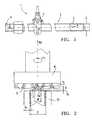
- FIG. 1is a view of a gas manifold for a cooking appliance, with a closure at one end of the tubular conduit.
- FIG. 2is a partial view of the end of the distributor pipe of FIG. 1 , showing the form of the closure and the rotary tool used to produce it.
- an embodiment of gas manifold 1 for installation on a cooking rangecomprises a distributor conduit 2 made by means of a long, thin-wall alloy pipe 3 , preferably of cylindrical cross section, with an open end 4 of the conduit for the intake of a flow Q for the gas supply of the cooking range at a pressure “P”, a number of regulating taps 5 which distribute the partial flows Q 1 supplied to the range and an end 6 of the pipe with an end closure 7 , which has been formed for safety against leakage of gas of said flow Q at pressure “P”.
- a cylindrical pipe 3is made in particular of an alloy with a low softening temperature such as aluminium or corrosion-resistant aluminized steel.
- the pipe 3is chosen of a diameter “D” in keeping with the regulating tap model 5 and its fastening to the distributor conduit 2 .
- Ddiameter
- Tothinnest possible original pipe wall thickness
- the small metallic mass of the end 6 of formed pipealso simplifies the closure operation carried out as described below by means of friction until achieving a temperature for the softening of the metal in the circular aluminium wall “To”.
- the original alloy pipe for carrying out the distributor conduit 2is free of welds and does not corrode, so its wall is gastight in itself.
- FIG. 1the end of pipe 6 prior to the closure operation is represented with a dash line.
- the forming tool 8 used to execute the closure 6provided with two rotary rollers 9 that operate from two opposite sides of the pipe end 6 , the latter is converted into a closure wall 7 , wherein the circular edge of the end 6 of the pipe has been welded.
- the average thickness “Tc” of the closure wallis greater than the original thickness “To”, and in its central region a tip 7 a is formed of greater metal mass in relation to the peripheral closure wall 7 .
- the thickness or height “H” of the tipintentionally pronounced in order to carry out a compaction of the metal free of cracks in the central region 7 a of the closure.
- the original pipe 3is positioned in a fastening device 10 , which leaves the end of pipe 6 protruding as represented in FIG. 1 .
- the forming tool 8is positioned encircling the end of pipe 6 .
- the forming toolhas to be provided with at least two rollers 9 in order to carry out said thickening of the tip wall 7 a in the central region of the closure.
- the forming toolcarries out a traversing movement “Ma” and a rotation movement “Mr”, while the rollers 9 rotate at sufficiently high speed to the friction heat required to soften the wall metal of the end 6 and to carry out the compaction process.
- both rollers 9exert ( FIG. 2 ) a centripetal radial force “Fr” at the same time as an axial force “Fa” against the aluminium mass conferring the form of a tip 7 a on the closure wall, the cross section of which, as shown in FIG. 2 , has said thickening or tip 7 a of height “H”, considerably larger than the original thickness “To” of the wall of pipe 3 .
- the conical form acquired by said closure tip 7 ais the resultant effect of the counterposed gripping forces “Fr” on the metallic mass exerted between the two rollers 9 , the edges of which go on making contact at different heights of said tip 7 a in line with the axial movement “Ma”.
- the pipe end closureis assured of being free of cracks and completely sealed at an actual pressure of the gas flow Q.
Landscapes
- Engineering & Computer Science (AREA)
- Mechanical Engineering (AREA)
- Chemical & Material Sciences (AREA)
- Combustion & Propulsion (AREA)
- General Engineering & Computer Science (AREA)
- Feeding And Controlling Fuel (AREA)
- Shaping Metal By Deep-Drawing, Or The Like (AREA)
- Pressure Welding/Diffusion-Bonding (AREA)
Abstract
Description
The present invention relates to a gas manifold with a number of regulating taps installed on a flow distributor pipe, wherein one of the ends of the manifold pipe is sealed hermetically.
Fuel gas manifolds fitted with rotary type manual taps are already known. They are installed on a panel of the frame of the cooking appliance with the control shafts of the taps aligned on a front panel of the cooking appliance. One of the ends of the manifold pipe is open for the connection of a hose for the supply of the fuel gas to the manifold, while the opposite end is sealed hermetically to prevent any leakage of gas. The gas flow manifold is preferably made of a long thin-wall pipe, made of aluminium or steel alloy with corrosion-resistant aluminium. The thinnest possible thickness of the wall on each of the pipes is determined in accordance with the strength required for handling and/or the strength necessary for machining and connection of the taps to the manifold conduit. The end of the pipe may be sealed for instance by means of the formation of the circular wall of the pipe and the closure finished off in the middle of the diameter by means of a welding with addition of metal.
A known example of a gas manifold for a cooking appliance is disclosed in U.S. Pat. No. 6,237,638-B1, wherein the manifold pipe is sealed at one end by means of an operation of rotation of a tool or roller working in the inward radial direction of the pipe, while the central region is welded by means of a process of compacting the fused metal in order to assure an airtight seal in the centre of the end wall.
A further example of a seal on a metal pipe is disclosed in JP-59125220, with a method for the sealing of an end of alloy pipe by means of the rotation of a roller, which generates the softening temperature of the metal, due to friction with the wall of the pipe, and the wall is therefore deformed inwards in a radial direction, until achieving the complete closure of the end of the pipe without addition of metal.
In the examples quoted from the prior art the resultant thickness of the closure wall after compacting the metal, although greater than the original thickness of the pipe, is not sufficient to assure a weld in the central region without gas leakage.
The object of the invention is a gas manifold fitted with a number of manual taps interspaced along the distributor conduit made of aluminium, or a similar corrosion-resistant alloy and adapted for the supply of a gas flow to a cooking appliance, wherein the opposite end of the pipe is sealed hermetically without addition of metal by means of the radial compaction of the wall of the end of the pipe softened by the friction of at least one rotation tool, wherein the wall of the closure is assured in order to withstand the pressure of the gas flow without any leakage.
The closure of the end of an alloy distributor pipe must be a wall without any cracks and, in particular, its central region must be controlled, which has to be of a sufficient thickness to eliminate cracks and thereby be able to withstand the pressure of the gas flow without any gas leakage whatsoever.
The gastight seal of the pipe end achieved according to the invention, results with a wall thickness greater than that of the original pipe and, in particular, in its central region it is of a thickness considerably greater enlarged with a tip, which withstands the real pressure of the gas flow distributed and assures the tightness in all the pipe closures made.
In reference toFIG. 1 andFIG. 2 , an embodiment of gas manifold1 for installation on a cooking range comprises adistributor conduit 2 made by means of a long, thin-wall alloy pipe3, preferably of cylindrical cross section, with an open end4 of the conduit for the intake of a flow Q for the gas supply of the cooking range at a pressure “P”, a number of regulatingtaps 5 which distribute the partial flows Q1 supplied to the range and an end6 of the pipe with anend closure 7, which has been formed for safety against leakage of gas of said flow Q at pressure “P”. A cylindrical pipe3 is made in particular of an alloy with a low softening temperature such as aluminium or corrosion-resistant aluminized steel. The pipe3 is chosen of a diameter “D” in keeping with the regulatingtap model 5 and its fastening to thedistributor conduit 2. For economic reasons the thinnest possible original pipe wall thickness “To” is chosen, capable of conferring on pipe3 the strength necessary for its handling. The small metallic mass of the end6 of formed pipe also simplifies the closure operation carried out as described below by means of friction until achieving a temperature for the softening of the metal in the circular aluminium wall “To”. The original alloy pipe for carrying out thedistributor conduit 2 is free of welds and does not corrode, so its wall is gastight in itself.
InFIG. 1 the end of pipe6 prior to the closure operation is represented with a dash line. As a result of the formingtool 8 used to execute the closure6, provided with tworotary rollers 9 that operate from two opposite sides of the pipe end6, the latter is converted into aclosure wall 7, wherein the circular edge of the end6 of the pipe has been welded. The average thickness “Tc” of the closure wall is greater than the original thickness “To”, and in its central region atip 7ais formed of greater metal mass in relation to theperipheral closure wall 7. The thickness or height “H” of the tip intentionally pronounced in order to carry out a compaction of the metal free of cracks in thecentral region 7aof the closure.
To carry out the operation for the sealing of the end of the pipe6, the original pipe3 is positioned in afastening device 10, which leaves the end of pipe6 protruding as represented inFIG. 1 . The formingtool 8 is positioned encircling the end of pipe6. The forming tool has to be provided with at least tworollers 9 in order to carry out said thickening of thetip wall 7ain the central region of the closure. Thus, the forming tool carries out a traversing movement “Ma” and a rotation movement “Mr”, while therollers 9 rotate at sufficiently high speed to the friction heat required to soften the wall metal of the end6 and to carry out the compaction process.
By means of a combination of the axial movement Ma and the rotational movement Mr made by thecompaction tool 8, bothrollers 9 exert (FIG. 2 ) a centripetal radial force “Fr” at the same time as an axial force “Fa” against the aluminium mass conferring the form of atip 7aon the closure wall, the cross section of which, as shown inFIG. 2 , has said thickening ortip 7aof height “H”, considerably larger than the original thickness “To” of the wall of pipe3. The conical form acquired bysaid closure tip 7ais the resultant effect of the counterposed gripping forces “Fr” on the metallic mass exerted between the tworollers 9, the edges of which go on making contact at different heights of saidtip 7ain line with the axial movement “Ma”. As a result of the compaction pressure exerted on the softened metal between the two rollers, the pipe end closure is assured of being free of cracks and completely sealed at an actual pressure of the gas flow Q. In the preferred embodiment described here, we have a base “W” of saidtip 7awhose size in relation to the original thickness “To” of the pipe is around W=6×To and the height of the section of thetip 7ais around H=3×To.
Claims (12)
1. A gas manifold for a cooking appliance comprising: a pipe having an open first end and a hermetically sealed second end, a longitudinal length of the pipe adjacent the sealed second end having a first wall thickness, the sealed second end comprising a closure wall of non-uniform curvature, the closure wall having a central conical wall portion that is annularly bound by a concave wall portion, the average thickness of the closure wall being greater than the first wall thickness.
2. A gas manifold according toclaim 1 , wherein the closure wall has a central tip region having a width dimension (W) and a height dimension (H), the width dimension of the central tip region being greater than the height dimension of the central tip region.
3. A gas manifold according toclaim 1 , wherein the closure wall has a central tip region having a height dimension (H) considerably larger than the first wall thickness.
4. A gas manifold according toclaim 1 , wherein the closure wall has a central tip region having a height dimension (H) around three times the first wall thickness.
5. A gas manifold according toclaim 1 , wherein the closure wall has a central tip region having a base dimension (W) around six times the first wall thickness.
6. A gas manifold according toclaim 1 , wherein the closure wall has a central tip region having a base dimension (W) around six times the first wall thickness and a height dimension (H) around three times the first wall thickness.
7. A gas manifold according toclaim 1 , wherein the pipe is made of aluminium or a steel alloy comprising corrosion-resistant aluminium.
8. A gas manifold according toclaim 1 , wherein the pipe is made of a low softening temperature metal alloy.
9. A gas manifold for a cooking appliance comprising: a pipe made of a low softening temperature metal alloy and having an open first end and a hermetically sealed second end, a longitudinal length of the pipe adjacent the sealed second end having a first wall thickness, the sealed second end comprising a closure wall of non-uniform curvature, the closure wall having a central conical wall portion that is annularly bound by a concave wall portion, the average thickness of the closure wall being greater than the first wall thickness, the closure wall having a pronounced central tip region, the central tip region having a height dimension (H) that is considerably larger than the first wall thickness.
10. A gas manifold according toclaim 9 , wherein the central tip region has a height dimension (H) around three times the first wall thickness.
11. A gas manifold according toclaim 9 , wherein the central tip region has a base dimension (W) around six times the first wall thickness.
12. A gas manifold according toclaim 9 , wherein the central tip region has a base dimension (W) around six times the first wall thickness and a height dimension (H) around three times the first wall thickness.
Applications Claiming Priority (3)
| Application Number | Priority Date | Filing Date | Title |
|---|---|---|---|
| ESP-200501495 | 2005-08-03 | ||
| ES200501945 | 2005-08-03 | ||
| ES200501945AES2304269B1 (en) | 2005-08-03 | 2005-08-03 | GAS DISTRIBUTOR FOR A KITCHEN, WITH A TUBE CLOSURE. |
Publications (2)
| Publication Number | Publication Date |
|---|---|
| US20070028915A1 US20070028915A1 (en) | 2007-02-08 |
| US7861706B2true US7861706B2 (en) | 2011-01-04 |
Family
ID=39410082
Family Applications (1)
| Application Number | Title | Priority Date | Filing Date |
|---|---|---|---|
| US11/492,503Expired - Fee RelatedUS7861706B2 (en) | 2005-08-03 | 2006-07-24 | Gas manifold for a cooking range, with a pipe closure |
Country Status (3)
| Country | Link |
|---|---|
| US (1) | US7861706B2 (en) |
| EP (1) | EP1760405A3 (en) |
| ES (1) | ES2304269B1 (en) |
Cited By (24)
| Publication number | Priority date | Publication date | Assignee | Title |
|---|---|---|---|---|
| US20080149872A1 (en)* | 2006-12-22 | 2008-06-26 | David Deng | Valve assemblies for heating devices |
| US20080227045A1 (en)* | 2007-03-15 | 2008-09-18 | David Deng | Fuel selectable heating devices |
| US20100035196A1 (en)* | 2006-12-22 | 2010-02-11 | David Deng | Pilot assemblies for heating devices |
| US20100037884A1 (en)* | 2006-05-17 | 2010-02-18 | David Deng | Dual fuel heater |
| US20100067908A1 (en)* | 2005-09-29 | 2010-03-18 | Broadlight, Ltd. | Enhanced Passive Optical Network (PON) Processor |
| US20100170503A1 (en)* | 2006-05-17 | 2010-07-08 | David Deng | Heater configured to operate with a first or second fuel |
| US20100304317A1 (en)* | 2006-12-22 | 2010-12-02 | David Deng | Control valves for heaters and fireplace devices |
| US20100330518A1 (en)* | 2009-06-29 | 2010-12-30 | David Deng | Heat engine with nozzle |
| US20110081620A1 (en)* | 2006-05-17 | 2011-04-07 | Continental Appliances, Inc. D.B.A. Procom | Oxygen depletion sensor |
| US8241034B2 (en) | 2007-03-14 | 2012-08-14 | Continental Appliances Inc. | Fuel selection valve assemblies |
| US8752541B2 (en) | 2010-06-07 | 2014-06-17 | David Deng | Heating system |
| US8985094B2 (en) | 2011-04-08 | 2015-03-24 | David Deng | Heating system |
| US9423123B2 (en) | 2013-03-02 | 2016-08-23 | David Deng | Safety pressure switch |
| US9671111B2 (en) | 2013-03-13 | 2017-06-06 | Ghp Group, Inc. | Fuel selector valve with shutter mechanism for a gas burner unit |
| US9739389B2 (en) | 2011-04-08 | 2017-08-22 | David Deng | Heating system |
| US9752779B2 (en) | 2013-03-02 | 2017-09-05 | David Deng | Heating assembly |
| US9752782B2 (en) | 2011-10-20 | 2017-09-05 | David Deng | Dual fuel heater with selector valve |
| US9829195B2 (en) | 2009-12-14 | 2017-11-28 | David Deng | Dual fuel heating source with nozzle |
| US10073071B2 (en) | 2010-06-07 | 2018-09-11 | David Deng | Heating system |
| US20190030973A1 (en)* | 2016-03-30 | 2019-01-31 | Nhk Spring Co., Ltd. | Hollow coil spring and suspension device for vehicle |
| US10222057B2 (en) | 2011-04-08 | 2019-03-05 | David Deng | Dual fuel heater with selector valve |
| US10240789B2 (en) | 2014-05-16 | 2019-03-26 | David Deng | Dual fuel heating assembly with reset switch |
| US10429074B2 (en) | 2014-05-16 | 2019-10-01 | David Deng | Dual fuel heating assembly with selector switch |
| US11701943B2 (en) | 2016-03-30 | 2023-07-18 | Nhk Spring Co., Ltd | Method of manufacturing a hollow spring member |
Families Citing this family (2)
| Publication number | Priority date | Publication date | Assignee | Title |
|---|---|---|---|---|
| ES2363143B1 (en) | 2009-03-27 | 2012-06-13 | Bsh Electrodomésticos España, S.A. | TUBULAR ELEMENT, GAS OPERATED APPLIANCE AND PROCEDURE FOR THE MANUFACTURE OF A TUBULAR ELEMENT. |
| JP2016049544A (en)* | 2014-08-29 | 2016-04-11 | 日立オートモティブシステムズ株式会社 | Closing work method of tube, and device of the same |
Citations (52)
| Publication number | Priority date | Publication date | Assignee | Title |
|---|---|---|---|---|
| US1458196A (en)* | 1921-07-05 | 1923-06-12 | Wehrle Co | Gas range |
| US1701411A (en)* | 1928-01-16 | 1929-02-05 | David S Kellam | Shut-off for fire hose |
| US1877342A (en)* | 1930-06-17 | 1932-09-13 | Aluminum Screw Machine Product | Method of making quills |
| US2136007A (en)* | 1936-06-02 | 1938-11-08 | Harold S Gish | Collapsible tube and method of making the same |
| US2212801A (en)* | 1937-09-27 | 1940-08-27 | Everyl M Torbert | Pliers |
| US2406059A (en)* | 1943-06-10 | 1946-08-20 | Linde Air Prod Co | Process of spinning hollow articles |
| US2408596A (en) | 1944-03-13 | 1946-10-01 | Nat Tube Co | Method of forming cylinder ends |
| US2421629A (en)* | 1943-02-10 | 1947-06-03 | Otto A Langos | Method for closing the ends of metal tubes |
| US2524420A (en)* | 1947-09-20 | 1950-10-03 | Earle A Blampin | Spinning-in the ends of tubes |
| US2663206A (en)* | 1950-03-15 | 1953-12-22 | Whiting Tubular Products Inc | Method and means for producing closed end tubing |
| US2699596A (en)* | 1948-06-09 | 1955-01-18 | Union Carbide & Carbon Corp | Process of making gas pressure cylinders having walls with improved uniformity in thickness |
| US2709381A (en)* | 1952-10-28 | 1955-05-31 | Enghauser Mfg Company Inc | Pipe closing machine |
| US2754705A (en)* | 1951-11-14 | 1956-07-17 | Enghauser Mfg Company Inc | Pipe closing apparatus |
| US2825525A (en)* | 1953-12-22 | 1958-03-04 | David S Kellam | Hose clamp |
| US2896975A (en)* | 1955-10-19 | 1959-07-28 | Cribben And Sexton Company | Pipe manifold and method of making |
| US2971554A (en)* | 1954-02-08 | 1961-02-14 | Bundy Tubing Co | Shaping of ends of hollow work pieces |
| US3090263A (en)* | 1957-03-15 | 1963-05-21 | Murray Mfg Corp | Sealed tube |
| US3094349A (en)* | 1961-04-03 | 1963-06-18 | Amp Inc | Handling device |
| US3145465A (en)* | 1961-08-24 | 1964-08-25 | Gen Electric | Tubulation sealing apparatus and method |
| US3225998A (en)* | 1962-06-18 | 1965-12-28 | Gas Appliance Supply Corp | Apparatus for closing the ends of pipes |
| US3260098A (en)* | 1963-09-06 | 1966-07-12 | John B Gill | Tool for closing and opening a metal tube |
| US3475786A (en)* | 1966-12-30 | 1969-11-04 | Medical Supply Co | Tube closing machine |
| US3496747A (en)* | 1967-09-21 | 1970-02-24 | Nordberg Manufacturing Co | Numerically controlled spinning machine |
| US3748883A (en)* | 1972-01-03 | 1973-07-31 | Toshiba Machine Co Ltd | Spinning lathe |
| US3793863A (en) | 1971-07-09 | 1974-02-26 | D Groppini | Device for the manufacture of metal cylinders |
| US4061009A (en)* | 1976-11-10 | 1977-12-06 | Kaporovich Vladimir Georgievic | Machine for spinning tubular workpieces |
| US4083677A (en)* | 1976-09-22 | 1978-04-11 | Bloom Engineering Company, Inc. | Method and apparatus for heating a furnace chamber |
| US4181491A (en)* | 1976-09-22 | 1980-01-01 | Bloom Engineering Company, Inc. | Method and apparatus for heating a furnace chamber |
| US4304433A (en)* | 1980-03-17 | 1981-12-08 | Bj-Hughes Inc. | Pipe gripping head |
| US4320848A (en)* | 1979-06-07 | 1982-03-23 | Dye Richard G | Deep drawn and ironed pressure vessel having selectively controlled side-wall thicknesses |
| US4439274A (en)* | 1980-10-11 | 1984-03-27 | Hartung, Kuhn & Co. Maschinenfabrik Gmbh | Method and chimney for reducing the emission of solid particles |
| JPS59125220A (en) | 1982-12-29 | 1984-07-19 | Showa Mfg Co Ltd | Closed end forming method of pipe |
| US4502310A (en)* | 1979-07-09 | 1985-03-05 | Gosudarstvenny Proektny I Konstruktorsky Institut Sojuzprommekhanizatsia | Conveyor roller and method of manufacture thereof |
| US4604051A (en)* | 1984-08-16 | 1986-08-05 | Gas Research Institute | Regenerative burner |
| US4627257A (en)* | 1980-05-05 | 1986-12-09 | Coilco, Inc. | Tube spin close apparatus |
| US5071102A (en)* | 1988-07-20 | 1991-12-10 | Rommie Gray | Pipe crimping tool |
| US5085131A (en)* | 1990-10-02 | 1992-02-04 | Prime Tube, Inc. | Hydraulic cylinder for automotive steering systems and the like |
| US5273252A (en)* | 1991-09-10 | 1993-12-28 | Gaz De France | Clamp for crimping a main, such as a gas pipe |
| US5333485A (en)* | 1992-02-24 | 1994-08-02 | Austria Metall Aktiengesellschaft | Process for flattening the end section of a tube |
| US5598729A (en)* | 1994-10-26 | 1997-02-04 | Tandem Systems, Inc. | System and method for constructing wall of a tube |
| EP0769337A1 (en) | 1995-10-18 | 1997-04-23 | MAGNETI MARELLI CLIMATIZZAZIONE S.r.l. | A method of closing an end of a metal pipe |
| US6000933A (en)* | 1997-04-04 | 1999-12-14 | Frederick, Sr.; Charles B | Variable burner orifice furnace manifold |
| US6169268B1 (en)* | 1998-12-30 | 2001-01-02 | Esterline & Sons, Inc. | Method and apparatus for forming the ends of metallic tubes |
| US6237638B1 (en) | 2000-06-26 | 2001-05-29 | Harper-Wyman Company | Manifold assembly for a gas range |
| US6467322B2 (en)* | 2000-03-15 | 2002-10-22 | Calsonic Kansei Corporation | Pipe shaping method |
| US6578532B1 (en)* | 2002-01-23 | 2003-06-17 | Gerald W. Rowley | Fuel vaporizing and mixing system and method |
| US6725698B2 (en)* | 2001-06-26 | 2004-04-27 | Sakamoto Industry Co., Ltd. | Method for forming tube end |
| US6758077B2 (en)* | 2001-08-10 | 2004-07-06 | Kayaba Industry Co., Ltd. | Manufacturing method of cylinder |
| US6766675B2 (en)* | 2001-04-18 | 2004-07-27 | Sango Co., Ltd. | Spindle mechanism |
| US20040181926A1 (en)* | 1999-09-20 | 2004-09-23 | Smith & Nephew, Inc., A Delaware Corporation | Making closed end tubes for surgical instruments |
| EP1488870A1 (en) | 2003-06-19 | 2004-12-22 | S.P.I.C.E. Group S.R.L. | Method and apparatus for sealing a pipe that conveys gases or liquids |
| US7195035B2 (en)* | 2005-03-01 | 2007-03-27 | Gm Global Technology Operations, Inc. | In-tank hydrogen distribution valve |
Family Cites Families (2)
| Publication number | Priority date | Publication date | Assignee | Title |
|---|---|---|---|---|
| GB1588376A (en)* | 1978-05-22 | 1981-04-23 | Tube Manipulations Ltd | Gas rails |
| US4413611A (en)* | 1981-05-04 | 1983-11-08 | Raytheon Company | Modular gas range compartment |
- 2005
- 2005-08-03ESES200501945Apatent/ES2304269B1/ennot_activeExpired - Fee Related
- 2006
- 2006-07-13EPEP06380198.9Apatent/EP1760405A3/ennot_activeWithdrawn
- 2006-07-24USUS11/492,503patent/US7861706B2/ennot_activeExpired - Fee Related
Patent Citations (53)
| Publication number | Priority date | Publication date | Assignee | Title |
|---|---|---|---|---|
| US1458196A (en)* | 1921-07-05 | 1923-06-12 | Wehrle Co | Gas range |
| US1701411A (en)* | 1928-01-16 | 1929-02-05 | David S Kellam | Shut-off for fire hose |
| US1877342A (en)* | 1930-06-17 | 1932-09-13 | Aluminum Screw Machine Product | Method of making quills |
| US2136007A (en)* | 1936-06-02 | 1938-11-08 | Harold S Gish | Collapsible tube and method of making the same |
| US2212801A (en)* | 1937-09-27 | 1940-08-27 | Everyl M Torbert | Pliers |
| US2421629A (en)* | 1943-02-10 | 1947-06-03 | Otto A Langos | Method for closing the ends of metal tubes |
| US2406059A (en)* | 1943-06-10 | 1946-08-20 | Linde Air Prod Co | Process of spinning hollow articles |
| US2408596A (en) | 1944-03-13 | 1946-10-01 | Nat Tube Co | Method of forming cylinder ends |
| US2524420A (en)* | 1947-09-20 | 1950-10-03 | Earle A Blampin | Spinning-in the ends of tubes |
| US2699596A (en)* | 1948-06-09 | 1955-01-18 | Union Carbide & Carbon Corp | Process of making gas pressure cylinders having walls with improved uniformity in thickness |
| US2663206A (en)* | 1950-03-15 | 1953-12-22 | Whiting Tubular Products Inc | Method and means for producing closed end tubing |
| US2754705A (en)* | 1951-11-14 | 1956-07-17 | Enghauser Mfg Company Inc | Pipe closing apparatus |
| US2709381A (en)* | 1952-10-28 | 1955-05-31 | Enghauser Mfg Company Inc | Pipe closing machine |
| US2825525A (en)* | 1953-12-22 | 1958-03-04 | David S Kellam | Hose clamp |
| US2971554A (en)* | 1954-02-08 | 1961-02-14 | Bundy Tubing Co | Shaping of ends of hollow work pieces |
| US2896975A (en)* | 1955-10-19 | 1959-07-28 | Cribben And Sexton Company | Pipe manifold and method of making |
| US3090263A (en)* | 1957-03-15 | 1963-05-21 | Murray Mfg Corp | Sealed tube |
| US3094349A (en)* | 1961-04-03 | 1963-06-18 | Amp Inc | Handling device |
| US3145465A (en)* | 1961-08-24 | 1964-08-25 | Gen Electric | Tubulation sealing apparatus and method |
| US3225998A (en)* | 1962-06-18 | 1965-12-28 | Gas Appliance Supply Corp | Apparatus for closing the ends of pipes |
| US3260098A (en)* | 1963-09-06 | 1966-07-12 | John B Gill | Tool for closing and opening a metal tube |
| US3475786A (en)* | 1966-12-30 | 1969-11-04 | Medical Supply Co | Tube closing machine |
| US3496747A (en)* | 1967-09-21 | 1970-02-24 | Nordberg Manufacturing Co | Numerically controlled spinning machine |
| US3793863A (en) | 1971-07-09 | 1974-02-26 | D Groppini | Device for the manufacture of metal cylinders |
| US3748883A (en)* | 1972-01-03 | 1973-07-31 | Toshiba Machine Co Ltd | Spinning lathe |
| US4181491A (en)* | 1976-09-22 | 1980-01-01 | Bloom Engineering Company, Inc. | Method and apparatus for heating a furnace chamber |
| US4083677A (en)* | 1976-09-22 | 1978-04-11 | Bloom Engineering Company, Inc. | Method and apparatus for heating a furnace chamber |
| US4061009A (en)* | 1976-11-10 | 1977-12-06 | Kaporovich Vladimir Georgievic | Machine for spinning tubular workpieces |
| US4320848A (en)* | 1979-06-07 | 1982-03-23 | Dye Richard G | Deep drawn and ironed pressure vessel having selectively controlled side-wall thicknesses |
| US4502310A (en)* | 1979-07-09 | 1985-03-05 | Gosudarstvenny Proektny I Konstruktorsky Institut Sojuzprommekhanizatsia | Conveyor roller and method of manufacture thereof |
| US4304433A (en)* | 1980-03-17 | 1981-12-08 | Bj-Hughes Inc. | Pipe gripping head |
| US4627257A (en)* | 1980-05-05 | 1986-12-09 | Coilco, Inc. | Tube spin close apparatus |
| US4439274A (en)* | 1980-10-11 | 1984-03-27 | Hartung, Kuhn & Co. Maschinenfabrik Gmbh | Method and chimney for reducing the emission of solid particles |
| JPS59125220A (en) | 1982-12-29 | 1984-07-19 | Showa Mfg Co Ltd | Closed end forming method of pipe |
| US4604051A (en)* | 1984-08-16 | 1986-08-05 | Gas Research Institute | Regenerative burner |
| US5071102A (en)* | 1988-07-20 | 1991-12-10 | Rommie Gray | Pipe crimping tool |
| US5085131A (en)* | 1990-10-02 | 1992-02-04 | Prime Tube, Inc. | Hydraulic cylinder for automotive steering systems and the like |
| US5273252A (en)* | 1991-09-10 | 1993-12-28 | Gaz De France | Clamp for crimping a main, such as a gas pipe |
| US5333485A (en)* | 1992-02-24 | 1994-08-02 | Austria Metall Aktiengesellschaft | Process for flattening the end section of a tube |
| US5598729A (en)* | 1994-10-26 | 1997-02-04 | Tandem Systems, Inc. | System and method for constructing wall of a tube |
| US5845527A (en)* | 1994-10-26 | 1998-12-08 | Tandem Systems, Inc. | System and method for constricting wall of a tube |
| EP0769337A1 (en) | 1995-10-18 | 1997-04-23 | MAGNETI MARELLI CLIMATIZZAZIONE S.r.l. | A method of closing an end of a metal pipe |
| US6000933A (en)* | 1997-04-04 | 1999-12-14 | Frederick, Sr.; Charles B | Variable burner orifice furnace manifold |
| US6169268B1 (en)* | 1998-12-30 | 2001-01-02 | Esterline & Sons, Inc. | Method and apparatus for forming the ends of metallic tubes |
| US20040181926A1 (en)* | 1999-09-20 | 2004-09-23 | Smith & Nephew, Inc., A Delaware Corporation | Making closed end tubes for surgical instruments |
| US6467322B2 (en)* | 2000-03-15 | 2002-10-22 | Calsonic Kansei Corporation | Pipe shaping method |
| US6237638B1 (en) | 2000-06-26 | 2001-05-29 | Harper-Wyman Company | Manifold assembly for a gas range |
| US6766675B2 (en)* | 2001-04-18 | 2004-07-27 | Sango Co., Ltd. | Spindle mechanism |
| US6725698B2 (en)* | 2001-06-26 | 2004-04-27 | Sakamoto Industry Co., Ltd. | Method for forming tube end |
| US6758077B2 (en)* | 2001-08-10 | 2004-07-06 | Kayaba Industry Co., Ltd. | Manufacturing method of cylinder |
| US6578532B1 (en)* | 2002-01-23 | 2003-06-17 | Gerald W. Rowley | Fuel vaporizing and mixing system and method |
| EP1488870A1 (en) | 2003-06-19 | 2004-12-22 | S.P.I.C.E. Group S.R.L. | Method and apparatus for sealing a pipe that conveys gases or liquids |
| US7195035B2 (en)* | 2005-03-01 | 2007-03-27 | Gm Global Technology Operations, Inc. | In-tank hydrogen distribution valve |
Cited By (54)
| Publication number | Priority date | Publication date | Assignee | Title |
|---|---|---|---|---|
| US20100067908A1 (en)* | 2005-09-29 | 2010-03-18 | Broadlight, Ltd. | Enhanced Passive Optical Network (PON) Processor |
| US8281781B2 (en) | 2006-05-17 | 2012-10-09 | Continental Appliances, Inc. | Dual fuel heater |
| US20100037884A1 (en)* | 2006-05-17 | 2010-02-18 | David Deng | Dual fuel heater |
| US8568136B2 (en) | 2006-05-17 | 2013-10-29 | Procom Heating, Inc. | Heater configured to operate with a first or second fuel |
| US20100170503A1 (en)* | 2006-05-17 | 2010-07-08 | David Deng | Heater configured to operate with a first or second fuel |
| US8516878B2 (en) | 2006-05-17 | 2013-08-27 | Continental Appliances, Inc. | Dual fuel heater |
| US7967007B2 (en) | 2006-05-17 | 2011-06-28 | David Deng | Heater configured to operate with a first or second fuel |
| US9416977B2 (en) | 2006-05-17 | 2016-08-16 | Procom Heating, Inc. | Heater configured to operate with a first or second fuel |
| US8235708B2 (en) | 2006-05-17 | 2012-08-07 | Continental Appliances, Inc. | Heater configured to operate with a first or second fuel |
| US20110081620A1 (en)* | 2006-05-17 | 2011-04-07 | Continental Appliances, Inc. D.B.A. Procom | Oxygen depletion sensor |
| US7967006B2 (en) | 2006-05-17 | 2011-06-28 | David Deng | Dual fuel heater |
| US9140457B2 (en) | 2006-05-30 | 2015-09-22 | David Deng | Dual fuel heating system and air shutter |
| US10066838B2 (en) | 2006-05-30 | 2018-09-04 | David Deng | Dual fuel heating system |
| US8317511B2 (en) | 2006-12-22 | 2012-11-27 | Continental Appliances, Inc. | Control valves for heaters and fireplace devices |
| US20100304317A1 (en)* | 2006-12-22 | 2010-12-02 | David Deng | Control valves for heaters and fireplace devices |
| US8297968B2 (en) | 2006-12-22 | 2012-10-30 | Continental Appliances, Inc. | Pilot assemblies for heating devices |
| US9328922B2 (en) | 2006-12-22 | 2016-05-03 | Procom Heating, Inc. | Valve assemblies for heating devices |
| US20100035196A1 (en)* | 2006-12-22 | 2010-02-11 | David Deng | Pilot assemblies for heating devices |
| US20080149872A1 (en)* | 2006-12-22 | 2008-06-26 | David Deng | Valve assemblies for heating devices |
| US8764436B2 (en) | 2006-12-22 | 2014-07-01 | Procom Heating, Inc. | Valve assemblies for heating devices |
| US8545216B2 (en) | 2006-12-22 | 2013-10-01 | Continental Appliances, Inc. | Valve assemblies for heating devices |
| US8011920B2 (en) | 2006-12-22 | 2011-09-06 | David Deng | Valve assemblies for heating devices |
| US8241034B2 (en) | 2007-03-14 | 2012-08-14 | Continental Appliances Inc. | Fuel selection valve assemblies |
| US9200801B2 (en) | 2007-03-14 | 2015-12-01 | Procom Heating, Inc. | Fuel selection valve assemblies |
| US9581329B2 (en) | 2007-03-14 | 2017-02-28 | Procom Heating, Inc. | Gas-fueled heater |
| US20080227045A1 (en)* | 2007-03-15 | 2008-09-18 | David Deng | Fuel selectable heating devices |
| US8152515B2 (en) | 2007-03-15 | 2012-04-10 | Continental Appliances Inc | Fuel selectable heating devices |
| US8757202B2 (en) | 2009-06-29 | 2014-06-24 | David Deng | Dual fuel heating source |
| US20100330519A1 (en)* | 2009-06-29 | 2010-12-30 | David Deng | Dual fuel heating source |
| US8757139B2 (en) | 2009-06-29 | 2014-06-24 | David Deng | Dual fuel heating system and air shutter |
| US20100330518A1 (en)* | 2009-06-29 | 2010-12-30 | David Deng | Heat engine with nozzle |
| US20100330513A1 (en)* | 2009-06-29 | 2010-12-30 | David Deng | Dual fuel heating source |
| US8517718B2 (en) | 2009-06-29 | 2013-08-27 | David Deng | Dual fuel heating source |
| US8465277B2 (en) | 2009-06-29 | 2013-06-18 | David Deng | Heat engine with nozzle |
| US20100326430A1 (en)* | 2009-06-29 | 2010-12-30 | David Deng | Dual fuel heating system and air shutter |
| US9829195B2 (en) | 2009-12-14 | 2017-11-28 | David Deng | Dual fuel heating source with nozzle |
| US10073071B2 (en) | 2010-06-07 | 2018-09-11 | David Deng | Heating system |
| US8851065B2 (en) | 2010-06-07 | 2014-10-07 | David Deng | Dual fuel heating system with pressure sensitive nozzle |
| US8752541B2 (en) | 2010-06-07 | 2014-06-17 | David Deng | Heating system |
| US9021859B2 (en) | 2010-06-07 | 2015-05-05 | David Deng | Heating system |
| US9739389B2 (en) | 2011-04-08 | 2017-08-22 | David Deng | Heating system |
| US10222057B2 (en) | 2011-04-08 | 2019-03-05 | David Deng | Dual fuel heater with selector valve |
| US8985094B2 (en) | 2011-04-08 | 2015-03-24 | David Deng | Heating system |
| US9752782B2 (en) | 2011-10-20 | 2017-09-05 | David Deng | Dual fuel heater with selector valve |
| US9752779B2 (en) | 2013-03-02 | 2017-09-05 | David Deng | Heating assembly |
| US9441833B2 (en) | 2013-03-02 | 2016-09-13 | David Deng | Heating assembly |
| US9423123B2 (en) | 2013-03-02 | 2016-08-23 | David Deng | Safety pressure switch |
| US9671111B2 (en) | 2013-03-13 | 2017-06-06 | Ghp Group, Inc. | Fuel selector valve with shutter mechanism for a gas burner unit |
| US10429074B2 (en) | 2014-05-16 | 2019-10-01 | David Deng | Dual fuel heating assembly with selector switch |
| US10240789B2 (en) | 2014-05-16 | 2019-03-26 | David Deng | Dual fuel heating assembly with reset switch |
| US20190030973A1 (en)* | 2016-03-30 | 2019-01-31 | Nhk Spring Co., Ltd. | Hollow coil spring and suspension device for vehicle |
| US11254177B2 (en)* | 2016-03-30 | 2022-02-22 | Nhk Spring Co., Ltd. | Hollow coil spring and suspension device for vehicle |
| US11685211B2 (en) | 2016-03-30 | 2023-06-27 | Nhk Spring Co., Ltd | Hollow coil spring and suspension device for vehicle |
| US11701943B2 (en) | 2016-03-30 | 2023-07-18 | Nhk Spring Co., Ltd | Method of manufacturing a hollow spring member |
Also Published As
| Publication number | Publication date |
|---|---|
| EP1760405A2 (en) | 2007-03-07 |
| EP1760405A3 (en) | 2016-12-21 |
| ES2304269A1 (en) | 2008-10-01 |
| ES2304269B1 (en) | 2009-07-17 |
| US20070028915A1 (en) | 2007-02-08 |
Similar Documents
| Publication | Publication Date | Title |
|---|---|---|
| US7861706B2 (en) | Gas manifold for a cooking range, with a pipe closure | |
| CN208196014U (en) | A kind of anti-welding deformation tooling for starching spool | |
| US2896975A (en) | Pipe manifold and method of making | |
| CH643643A5 (en) | CORRUGATED STAINLESS STEEL PIPE AND METHOD FOR PRODUCING THE SAME. | |
| US3912307A (en) | Flanged joint sealing nut | |
| CN103115216B (en) | Method for repairing non-standard steel pipeline crack under working state | |
| CN105240640B (en) | A kind of Control rod drive line displacement compensation device, shaping dies and its manufacturing process | |
| US6237638B1 (en) | Manifold assembly for a gas range | |
| CN103752990B (en) | The method of a kind of combustible gas pipe racks pressure mending-leakage | |
| AU2017272290B2 (en) | Thick, Long Seam Welding System and Method for Distortion Control and Non Post Weld Heat Treatment of Pipeline Hot Tap Fittings | |
| CN201412634Y (en) | Metal Thick Wall Cracked Delivery Pipe Quick Repair Fittings | |
| CN208178104U (en) | The upper header device of nozzle can be replaced online | |
| US3003227A (en) | Methods for fabricating gas manifolds | |
| JP2012207677A (en) | Pipe end sealing device | |
| CN204952700U (en) | A annotate water mixer for high -pressure gas pipeline | |
| CN204320986U (en) | Spinning machine flame heating device | |
| CN206047323U (en) | A kind of welding argon-filling device for relying on waste and old cutting torch transformation to make | |
| US7290427B1 (en) | Clamp ring with pre-heater | |
| CN209856591U (en) | Inclined anti-hedging furnace tube collecting tube device | |
| CN114857983B (en) | Preparation method of flue gas bipolar heat exchanger for radiant tube burner | |
| CN222937443U (en) | A four-way structure for small-diameter pipelines | |
| CN219013635U (en) | Flange telescopic structure | |
| CN209325266U (en) | The ozzle of pressure vessel for oil vapor treatment | |
| CN104344153A (en) | Hoop leakage stoppage device for stopping leakage of tee joint pipes of gas conduit | |
| CN107498229A (en) | A kind of special line-up clamp of posted sides pipeline and preparation method thereof |
Legal Events
| Date | Code | Title | Description |
|---|---|---|---|
| AS | Assignment | Owner name:COPRECITEC, S.L., SPAIN Free format text:ASSIGNMENT OF ASSIGNORS INTEREST;ASSIGNOR:BELLOMO, ALBERTO;REEL/FRAME:018129/0970 Effective date:20060706 | |
| STCF | Information on status: patent grant | Free format text:PATENTED CASE | |
| FPAY | Fee payment | Year of fee payment:4 | |
| MAFP | Maintenance fee payment | Free format text:PAYMENT OF MAINTENANCE FEE, 8TH YEAR, LARGE ENTITY (ORIGINAL EVENT CODE: M1552) Year of fee payment:8 | |
| FEPP | Fee payment procedure | Free format text:MAINTENANCE FEE REMINDER MAILED (ORIGINAL EVENT CODE: REM.); ENTITY STATUS OF PATENT OWNER: LARGE ENTITY | |
| LAPS | Lapse for failure to pay maintenance fees | Free format text:PATENT EXPIRED FOR FAILURE TO PAY MAINTENANCE FEES (ORIGINAL EVENT CODE: EXP.); ENTITY STATUS OF PATENT OWNER: LARGE ENTITY | |
| STCH | Information on status: patent discontinuation | Free format text:PATENT EXPIRED DUE TO NONPAYMENT OF MAINTENANCE FEES UNDER 37 CFR 1.362 | |
| FP | Lapsed due to failure to pay maintenance fee | Effective date:20230104 |