US7861365B2 - Robotic vacuum cleaner - Google Patents
Robotic vacuum cleanerDownload PDFInfo
- Publication number
- US7861365B2 US7861365B2US11/537,656US53765606AUS7861365B2US 7861365 B2US7861365 B2US 7861365B2US 53765606 AUS53765606 AUS 53765606AUS 7861365 B2US7861365 B2US 7861365B2
- Authority
- US
- United States
- Prior art keywords
- vacuum cleaner
- robotic vacuum
- dust
- housing plate
- collecting
- Prior art date
- Legal status (The legal status is an assumption and is not a legal conclusion. Google has not performed a legal analysis and makes no representation as to the accuracy of the status listed.)
- Expired - Fee Related, expires
Links
Images


Classifications
- A—HUMAN NECESSITIES
- A47—FURNITURE; DOMESTIC ARTICLES OR APPLIANCES; COFFEE MILLS; SPICE MILLS; SUCTION CLEANERS IN GENERAL
- A47L—DOMESTIC WASHING OR CLEANING; SUCTION CLEANERS IN GENERAL
- A47L5/00—Structural features of suction cleaners
- A47L5/12—Structural features of suction cleaners with power-driven air-pumps or air-compressors, e.g. driven by motor vehicle engine vacuum
- A47L5/14—Structural features of suction cleaners with power-driven air-pumps or air-compressors, e.g. driven by motor vehicle engine vacuum cleaning by blowing-off, also combined with suction cleaning
- A—HUMAN NECESSITIES
- A47—FURNITURE; DOMESTIC ARTICLES OR APPLIANCES; COFFEE MILLS; SPICE MILLS; SUCTION CLEANERS IN GENERAL
- A47L—DOMESTIC WASHING OR CLEANING; SUCTION CLEANERS IN GENERAL
- A47L5/00—Structural features of suction cleaners
- A47L5/12—Structural features of suction cleaners with power-driven air-pumps or air-compressors, e.g. driven by motor vehicle engine vacuum
- A47L5/22—Structural features of suction cleaners with power-driven air-pumps or air-compressors, e.g. driven by motor vehicle engine vacuum with rotary fans
- A—HUMAN NECESSITIES
- A47—FURNITURE; DOMESTIC ARTICLES OR APPLIANCES; COFFEE MILLS; SPICE MILLS; SUCTION CLEANERS IN GENERAL
- A47L—DOMESTIC WASHING OR CLEANING; SUCTION CLEANERS IN GENERAL
- A47L9/00—Details or accessories of suction cleaners, e.g. mechanical means for controlling the suction or for effecting pulsating action; Storing devices specially adapted to suction cleaners or parts thereof; Carrying-vehicles specially adapted for suction cleaners
- A47L9/0081—Means for exhaust-air diffusion; Means for sound or vibration damping
- A—HUMAN NECESSITIES
- A47—FURNITURE; DOMESTIC ARTICLES OR APPLIANCES; COFFEE MILLS; SPICE MILLS; SUCTION CLEANERS IN GENERAL
- A47L—DOMESTIC WASHING OR CLEANING; SUCTION CLEANERS IN GENERAL
- A47L9/00—Details or accessories of suction cleaners, e.g. mechanical means for controlling the suction or for effecting pulsating action; Storing devices specially adapted to suction cleaners or parts thereof; Carrying-vehicles specially adapted for suction cleaners
- A47L9/009—Carrying-vehicles; Arrangements of trollies or wheels; Means for avoiding mechanical obstacles
- A—HUMAN NECESSITIES
- A47—FURNITURE; DOMESTIC ARTICLES OR APPLIANCES; COFFEE MILLS; SPICE MILLS; SUCTION CLEANERS IN GENERAL
- A47L—DOMESTIC WASHING OR CLEANING; SUCTION CLEANERS IN GENERAL
- A47L2201/00—Robotic cleaning machines, i.e. with automatic control of the travelling movement or the cleaning operation
- A47L2201/04—Automatic control of the travelling movement; Automatic obstacle detection
Definitions
- the present inventionrelates to a cleaning apparatus, and more particularly, to a robotic vacuum cleaner capable of vacuuming dust while maneuvering around obstacles in an autonomous manner.
- An autonomous vacuum cleanerbeing a fully automated cleaning device, is a renovating device different from those conventionally vacuum cleaners and other sweeping devices, that is can clean a specific area autonomously without any human attention and thus is foreseen to be the future cleaning device replacing those conventional manual-operated vacuum cleaners and other cleaning devices.
- an autonomous vacuum cleaneris able to maneuver around obstacles while performing a ground cleaning operation, even cleaning those usually considered as the dead spots of cleaning.
- the autonomous vacuum cleaneris a great help to daily household cleaning, its function is limited by its power source, which is not an alternating current (AC) power source, and by its own interior space, which limited the same from adopting those air compressors used in those conventional vacuum cleaners. Therefore, as the autonomous vacuum cleaner only has limited power supply, a good centrifugal fan is essential for enabling the same to have good performance. Nonetheless, the centrifugal fan is beneficial for its operating noise is lower than those conventional air compressors.
- ACalternating current
- TW Pat. No. I220383shows a conventional contact-type autonomous vacuuming cleaner.
- the aforesaid contact-type autonomous vacuuming cleaneris short in that: the drivers and the wheels used in the driving wheel module of the contact-type autonomous vacuuming cleaner is not detachable from the driver such that it is required to replace the whole driving wheel module when there is only required to repair a broken motor of a driver or to replace the tire of a wheel, which is costly.
- the aforesaid contact-type autonomous vacuuming cleaneris not adapted for cleaning dead spots so that it is not efficient when it comes to dead spot cleaning.
- the aforesaid cleanercan be attached with a mopping unit for using the same to perform a floor-mopping operation, it is important to remind a user to replace/clean the mopping unit constantly and periodically, otherwise, mopping floor with a dirty mopping unit is not a good idea for cleaning.
- the primary object of the present inventionis to provide a robotic vacuum cleaner capable of using a suspension means of its driving wheel module to lift the bottom thereof from the ground by a specific height, and thereby, enable the wheels thereof to cross over obstacles.
- Another object of the inventionto provide a robotic vacuum cleaner with obstacle maneuvering-around and missing-step prevention capabilities, by which the robotic vacuum cleaner can function efficiently and safely.
- Another object of the inventionto provide a low noise, high flow rate robotic vacuum cleaner with asymmetry fan housing design and uniform airflow channel.
- Another object of the inventionto provide a robotic vacuum cleaner capable of utilizing its specially designed dust-collecting case to assemble a centrifugal fan apparatus therein for enabling the robotic vacuum cleaner to perform a dust-collecting operation while maintaining the smoothness of airflow in the centrifugal fan apparatus.
- one further object of the inventionis to provide a robotic vacuum cleaner capable using a noise-reduced side-wind generation unit for blowing away and thus cleaning the dust accumulated around corners.
- the present inventionprovides a robotic vacuum cleaner: comprising: a controller, disposed on a housing plate; at least a driving wheel module, each being disposed on the housing plate while electrically connecting to the controller; and a dust-collecting module, disposed on the housing plate for vacuuming for filtering and collecting dust; wherein each driving wheel module further comprises: a driver; a wheel, connecting to the output shaft of the driver; a linkage rod, having two ends pivotally fixed on the housing plate and the driver respectively; and a resilience element, having two ends pivotally connected to the housing plate and the driver respectively.
- the dust-collecting modulefurther comprises: a dust-collecting case, having a vacuum inlet positioned under the housing plate; and a centrifugal fan unit, connected to the dust-collecting case by an intake end thereof for receiving air flow sucked from the vacuum inlet.
- the centrifugal fan unitis comprised of: a housing with an accommodating space, having an intake hole and an outflow hole; an impeller, arranging in the accommodating space while enabling an airflow channel of uniform width to be formed between a rim of the impeller and a side wall of the housing, and enabling the accommodating space to be divided into a first space and a second space by a virtual cross section passing the axial center of the impeller, referring as axial cross section hereinafter, for enabling the first space to be asymmetrical to the second space; and a driving device, connected to the impeller for driving the same to rotate; wherein a helical airflow channel is extending from the second space and channeling to the outflow hole in a manner that the sectional area of the helical airflow channel is increasing progressively from the beginning thereof to the outflow hole.
- the dust-collecting caseis comprised of: a case, having a recess and a through hole channeling to the recess, and a side thereof being arranged with a groove hole channeling to the recess; a dust-collecting lid, having the vacuum inlet arranged thereon while being connected to the groove hole; a box with a dust-collecting space, capable of being received in the recess for enabling the duct-collecting space to channel with the through hole and the groove hole.
- an edge of the housing plateis designed with a rake angle.
- a collision sensorelectrically connected to the controller, is arranged at a front end of the housing plate, which can be substantially a pressure sensor.
- the collision sensoris comprised of: a base; a resilience element, ensheathing the base; a pillar, having an end abutted against the resilience element; a first contact plate, connected to an end of the pillar not abutted against the resilience element; and a second contact plate, being arranged at a position corresponding to the first contact plate.
- each obstacle detection unitis arranged at the bottom of the housing plate while enabling each to be electrically connected to the controller.
- each obstacle detection unitis comprised of: a base; a resilience element, ensheathing the base; a pillar, having an end abutted against the resilience element; a first contact plate, connected to an end of the pillar not abutted against the resilience element; and a second contact plate, being arranged at a position corresponding to the first contact plate.
- a side-wind generation unitis arranged at a side of the housing plate, whereas the side-wind generation unit can be a centrifugal fan or an axial fan.
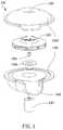
- FIG. 1is a schematic diagram showing a robotic vacuum cleaner according to a preferred embodiment of the invention.
- FIG. 2A to FIG. 2Care schematic views of a driving wheel module according to a preferred embodiment of the invention.
- FIG. 2Dis a schematic diagram showing a rake angle of a housing plate adopted in a robotic vacuum cleaner of the present invention.
- FIG. 3is a schematic diagram showing a dust-collecting module used in a robotic vacuum cleaner of the present invention.
- FIG. 4is an exploded diagram illustrating a centrifugal fan unit used in a robotic vacuum cleaner of the present invention.
- FIG. 5Ais a top view of a centrifugal fan unit used in a robotic vacuum cleaner of the present invention.
- FIG. 5Bis an axial sectional view of a centrifugal fan unit used in a robotic vacuum cleaner of the present invention.
- FIG. 6Ais a pictorial view of a dust-collecting case of the invention.
- FIG. 6Bis an exploded diagram illustrating a dust-collecting case of the invention.
- FIG. 6Cis a pictorial view of a dust-collecting lid of the invention.
- FIG. 6Dis a schematic diagram showing a brushing roller device used in a robotic vacuum cleaner of the present invention, whereas the roller is being driven to rotate.
- FIG. 7is a schematic diagram illustrating the disposition of a dust-collecting case on a housing plate according to a preferred embodiment of the invention.
- FIG. 8is a schematic diagram illustrating the disposition of a dust-collecting case on a housing plate according to another preferred embodiment of the invention.
- FIG. 9Ashows a collision sensor used in a robotic vacuum cleaner of the present invention.
- FIG. 9Bis a top view of FIG. 9A .
- FIG. 10Ais a side view of an obstacle detection unit used in a robotic vacuum cleaner of the present invention.
- FIG. 10Bis a schematic diagram showing an obstacle detection unit as it is being activated.
- FIG. 1is a schematic diagram showing a robotic vacuum cleaner according to a preferred embodiment of the invention.
- the robotic vacuum cleaner 1is comprised of a controller 11 , a pair of driving wheel modules 12 , a dust-collecting module 13 and a pair of collision sensors 14 .
- Each driving wheel module 12being disposed on a housing plate 10 and electrically connected to the controller 11 , is used for providing moving power to the robotic vacuum cleaner. It is noted that the driving wheel module is directed to act with respect to the signal transmitted from the controller 11 , and thus the robotic vacuum cleaner is driven thereby to move while performing a vacuuming operation.
- each driving wheel moduleis further comprised of a driver 120 , a wheel 123 , a linkage rod 121 and a resilience element 122 .
- the wheel 123is connected to an output shaft 124 of the driver 120 by an interfacing part 125 , by which power of the driver 120 can be transmitted to the wheel 123 for enabling the same to rotate.
- the wheel 123can be detached from the driver 120 , i.e. the wheel 123 is detachable, and thus the maintenance thereof can be facilitated.
- the linkage rod 121is connected to the driver 120 by an end thereof while another end thereof is connected to a seat 101 of the housing plate 10 .
- the resilience element 122is connected to the driver 120 by an end thereof while another end thereof is connected to another seat 102 of the housing plate 10 .
- the drivercan be an assembly of a motor and a gear reducer.
- the driver 120will have contacted with the housing plate 10 according to the weight disposition of the robotic vacuum cleaner 1 , as seen in FIG. 2B . Nevertheless, as seen in FIG. 2C that the wheel 123 is contacting to ground 5 , the driver 120 is separated from the housing plate 10 by a distance that the distance can be considered as the height limit that the robotic vacuum cleaner 1 capable of crossing-over. In a circumstance that the robotic vacuum cleaner 1 is crossing over an obstacle on the ground, the housing plate will be lift and thus the distance between the driver 120 and the housing plate 10 is narrowed, as seen in FIG. 2D . Therefore, it is preferred to design an edge of the housing plate 10 with a rake angle 10 so as to facilitate the crossing-over.
- FIG. 3is a schematic diagram showing a dust-collecting module used in a robotic vacuum cleaner of the present invention.
- the dust-collecting module 13is comprised of a centrifugal fan unit 130 and a dust-collecting case 131 .
- FIG. 4is an exploded diagram illustrating a centrifugal fan unit used in a robotic vacuum cleaner of the present invention.
- the centrifugal fan unit 130is further composed of a housing, an impeller 1302 and a driving device 1307 .
- the housingwhich is composed of a top shell 1300 and a bottom shell 1305 , is different from those conventional centrifugal fan with spiral-shaped housing in that: the axial cross section of an accommodating space formed by the assembling of the top shell 1300 and the bottom shell 1305 is shaped as a disc, which is different from those of prior arts.
- an intake hole 1301is formed at the center of the top shell 1300
- an outflow hole 1306is formed at a side of the bottom shell 1305 .
- the driving device 1307is connected to the impeller 1302 by a pin 1303 and an interfacing panel 1304 so that the impeller 1302 can be driven to rotate by the driving device 1307 .
- FIG. 5Ais a top view of a centrifugal fan unit according to the present invention.
- FIG. 5Athe manner that the impeller 1302 is being arranged inside the housing is illustrated.
- an airflow channel 1308 of uniform width Dcan be formed between a rim of the impeller 1302 and a side wall of the housing.
- FIG. 5Bwhich is a cross sectional view of a centrifugal fan unit according to the present invention.
- FIG. 5Bis a cross sectional view of a centrifugal fan unit according to the present invention.
- the accommodating spaceis being divided into a first space A 1 and a second space A 2 by a virtual cross section 8 passing the axial center of the impeller 1302 while enabling the first space A 1 to be asymmetrical to the second space A 2 .
- a helical airflow channel 1309is formed in the second space A 2 by the bottom shell 1305 whereas the sectional area of the helical airflow channel 1309 is increasing progressively from the beginning thereof to the outflow hole.
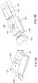
- FIG. 6A and FIG. 6Bare respectively a schematic diagram and an exploded diagram showing a dust-collect case according to a preferred embodiment of the invention.
- the ducts-collecting case 131further comprises: a case 1310 , having a recess 1318 and a through hole 1313 channeling to the recess 1318 ; a dust-collecting lid 1312 ; and a box 1311 ; wherein, a side of the case 1310 is arranged with a groove hole 1314 channeling to the recess 1318 ; the through hole 1313 is channeled to the intake hole 1301 of the centrifugal fan unit while an extractable filtering device is arranged between the through hole 1313 and intake hole 1301 of the centrifugal fan unit.
- the box 1311is formed with a dust-collecting space 1315 , which is capable of being received in the recess 1308 as a drawer while enabling the duct-collecting space 1315 to channel with the through hole 1313 and the groove hole 1314 .
- a duct-collecting bag received in the duct-collecting space 1315can be easily accessed and replaced as the box 1311 can be easily pulled out of the recess 1308 .
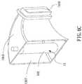
- FIG. 6Cis a schematic diagram showing a dust-collect lid according to a preferred embodiment of the invention. As seen in FIG.
- an intake 1317 and an outflow 1316are formed on the dust-collecting lid 1312 while the intake 1317 is channeled with the groove hole 1314 of the case 1310 .
- a brushing roller device 15can be arranged at the intake 1317 of the dust-collecting lid 1312 .
- the brushing roller device 15includes a brush 150 arranged at the intake of the dust-collecting lid 1312 , and a speed reducer 151 capable of driving the brush 150 to rotate.
- the speed reducer 151being composed of a motor and a gear box, is connected to a first gear 152 by an end thereof while the brush 150 is connected to a second gear 153 by an end thereof, whereas both the first and the second gears 152 , 153 can be driven to rotate by a belt 154 .
- the parts used in the speed reducerare the same as those used in the driver of aforesaid driving wheel module. However, it can be an assembly of less torque.
- the intake hole of its centrifugal fan unitis connected to the dust-collecting case through the dust-collecting lid 1312 while arranging the opening of the groove hole 1314 of the case 1310 at a side thereof instead of at the bottom thereof, by which the airflow channel is not twist for the consideration of improving dust-collecting efficiency and thus noise is reduced.
- the case 1310 and the box 1311are structured as a drawer that the box 1311 can be pull out of the case 1310 easily, not only it is good for noise reduction, but also it is good for dust cleaning and filer replacing.
- FIG. 7is a schematic diagram illustrating the disposition of a dust-collecting case on a housing plate according to a preferred embodiment of the invention.
- a helical airflow channel 1309is formed extending from the outflow hole 1306 toward a side of case 1310 , but not the bottom thereof, by which air blowing out of the centrifugal fan unit can be directed to those conventionally considered as dead spots.
- air flow 90is directed to blow toward a corner formed between a wall 3 and the robotic vacuum cleaner 1 , dust accumulated at the corner is being blown away and thus can be vacuumed by the robotic vacuum cleaner 1 .
- FIG. 8is a schematic diagram illustrating the disposition of a dust-collecting case on a housing plate according to another preferred embodiment of the invention.
- the robotic vacuum cleanerfurther comprises a side-wind generation unit 17 , which is arranged on the housing plate 10 and used for providing a sideway air flow.
- the side-wind generation unit 17can be a centrifugal fan device or an axial fan device, but is not limited thereby. That, is, it can be any device capable of generating side wind for blowing dust accumulated at dead spots.
- the collision prevention mechanism of the inventionis designed to be disposed at edges of the robotic vacuum cleaner of the invention.
- One such collision prevention mechanismcan be the collision sensor 14 , as shown in FIG. 9A .
- the collision sensoris comprised of: a base 142 , a pillar 143 , a first contact plate 144 , a second contact plate 145 and a contacting part 147 .
- the base 142is fixed to a fixing end 140 while the fixing end 140 is fixedly arranged on the housing plate 10 .
- the pillar 143is slidably ensheathed by the base 142 while an end thereof is connected to the first contact plate 144 .
- a resilience element 141is sandwiched between the first contact plate 144 and the fixing end 140 while the second contact plate 145 is arranged on the housing plate 10 at a position corresponding to the first contact plate 144 .
- both the first and the second contact plates 144 , 145are electrically connected to the controller 11 .
- a post 146boring through the housing plate 10 , is arranged to connected to a surface of the first contact plate 144 by an end thereof while another end of the post 146 is connected to the contacting part 147 .
- the resilience force of the resilience element 141will force the first contact plate 144 to contact with the second contact plate 145 as shown in FIG. 9B .
- the collision of the robotic vacuum sensor 1 and the obstacle 4will cause the collision sensor 14 to contact with the obstacle 4 , and thus push the contacting part 147 to withdraw and separate the first contact plate 144 from the second contact plate 145 while compressing the resilience element 141 .
- the controller 11sensing the change of electrically properties, is notified of the existence of the obstacle 4 , that the controller 11 will issue a command to control the driving wheel module for maneuvering around the obstacle 4 . It is noted that the amount and disposition position of the collision sensor are dependent on actual requirement.
- a plurality of obstacle detection units 16can arranged at the bottom of the housing plate for evaluating the ground flatness or determining whether there is a drop on the ground.
- FIG. 10Ais a side view of an obstacle detection unit used in a robotic vacuum cleaner of the present invention.
- the obstacle detection unit 16is composed of a base 162 , a pillar 163 , a first contact plate 164 , a second contact plate 165 and a contacting part 167 .
- the base 162is fixed to a fixing end 160 while the fixing end 160 is fixedly arranged on the housing plate 10 .
- the pillar 163is slidably ensheathed by the base 162 while an end thereof is connected to the first contact plate 164 . It is noted that a resilience element 161 is sandwiched between the first contact plate 164 and the fixing end 160 while the second contact plate 165 is arranged on the housing plate 10 at a position corresponding to the first contact plate 164 . Moreover, both the first and the second contact plates 164 , 165 are electrically connected to the controller 11 .
- a post 166boring through the housing plate 10 , is arranged to connected to a surface of the first contact plate 164 by an end thereof while another end of the post 166 is connected to the contacting part 167 , whereas the contacting part 167 is positioned to face toward for readying to contact the ground.
- the contacting part 167is in contact with the ground, it is driving to roll with the movement of the robotic vacuum sensor 1 .
- FIG. 10Ais a schematic diagram showing an obstacle detection unit as it is being activated.
- the obstacle detection unit 16is relived from the pressing force of the ground that release the compression of the resilience element 161 and thus the resilience force the resilience element 161 will push the first contact plate 164 to contact the second contact plate 165 .
- the controller 11sensing the change of electrically properties, is notified of the fall, that the controller 11 will issue a command to control the driving wheel module for maneuvering around the obstacle 4 . It is noted that the amount and disposition position of the collision sensor are dependent on actual requirement.
Landscapes
- Engineering & Computer Science (AREA)
- Mechanical Engineering (AREA)
- Electric Vacuum Cleaner (AREA)
Abstract
Description
Claims (19)
Applications Claiming Priority (3)
| Application Number | Priority Date | Filing Date | Title |
|---|---|---|---|
| TW095134528 | 2006-09-19 | ||
| TW095134528ATWI312279B (en) | 2006-09-19 | 2006-09-19 | Robotic vacuum cleaner |
| TW95134528A | 2006-09-19 |
Publications (2)
| Publication Number | Publication Date |
|---|---|
| US20080066257A1 US20080066257A1 (en) | 2008-03-20 |
| US7861365B2true US7861365B2 (en) | 2011-01-04 |
Family
ID=39187035
Family Applications (1)
| Application Number | Title | Priority Date | Filing Date |
|---|---|---|---|
| US11/537,656Expired - Fee RelatedUS7861365B2 (en) | 2006-09-19 | 2006-10-01 | Robotic vacuum cleaner |
Country Status (2)
| Country | Link |
|---|---|
| US (1) | US7861365B2 (en) |
| TW (1) | TWI312279B (en) |
Cited By (30)
| Publication number | Priority date | Publication date | Assignee | Title |
|---|---|---|---|---|
| US20120173064A1 (en)* | 2005-12-02 | 2012-07-05 | Chikyung Won | Modular Robot |
| US20130054022A1 (en)* | 2011-08-22 | 2013-02-28 | Samsung Electronics Co., Ltd. | Autonomous cleaner and method of controlling the same |
| US9119512B2 (en) | 2011-04-15 | 2015-09-01 | Martins Maintenance, Inc. | Vacuum cleaner and vacuum cleaning system and methods of use in a raised floor environment |
| US9811089B2 (en) | 2013-12-19 | 2017-11-07 | Aktiebolaget Electrolux | Robotic cleaning device with perimeter recording function |
| US9939529B2 (en) | 2012-08-27 | 2018-04-10 | Aktiebolaget Electrolux | Robot positioning system |
| US9946263B2 (en) | 2013-12-19 | 2018-04-17 | Aktiebolaget Electrolux | Prioritizing cleaning areas |
| US10045675B2 (en) | 2013-12-19 | 2018-08-14 | Aktiebolaget Electrolux | Robotic vacuum cleaner with side brush moving in spiral pattern |
| US10149589B2 (en) | 2013-12-19 | 2018-12-11 | Aktiebolaget Electrolux | Sensing climb of obstacle of a robotic cleaning device |
| US10209080B2 (en) | 2013-12-19 | 2019-02-19 | Aktiebolaget Electrolux | Robotic cleaning device |
| US10207408B1 (en) | 2015-12-07 | 2019-02-19 | AI Incorporated | Method to minimize collisions of mobile robotic devices |
| US10219665B2 (en) | 2013-04-15 | 2019-03-05 | Aktiebolaget Electrolux | Robotic vacuum cleaner with protruding sidebrush |
| US10231591B2 (en) | 2013-12-20 | 2019-03-19 | Aktiebolaget Electrolux | Dust container |
| US10433697B2 (en) | 2013-12-19 | 2019-10-08 | Aktiebolaget Electrolux | Adaptive speed control of rotating side brush |
| US10448794B2 (en) | 2013-04-15 | 2019-10-22 | Aktiebolaget Electrolux | Robotic vacuum cleaner |
| US10499778B2 (en) | 2014-09-08 | 2019-12-10 | Aktiebolaget Electrolux | Robotic vacuum cleaner |
| US10518416B2 (en) | 2014-07-10 | 2019-12-31 | Aktiebolaget Electrolux | Method for detecting a measurement error in a robotic cleaning device |
| US10534367B2 (en) | 2014-12-16 | 2020-01-14 | Aktiebolaget Electrolux | Experience-based roadmap for a robotic cleaning device |
| US10617271B2 (en) | 2013-12-19 | 2020-04-14 | Aktiebolaget Electrolux | Robotic cleaning device and method for landmark recognition |
| US10678251B2 (en) | 2014-12-16 | 2020-06-09 | Aktiebolaget Electrolux | Cleaning method for a robotic cleaning device |
| US10729297B2 (en) | 2014-09-08 | 2020-08-04 | Aktiebolaget Electrolux | Robotic vacuum cleaner |
| US10877484B2 (en) | 2014-12-10 | 2020-12-29 | Aktiebolaget Electrolux | Using laser sensor for floor type detection |
| US10874274B2 (en) | 2015-09-03 | 2020-12-29 | Aktiebolaget Electrolux | System of robotic cleaning devices |
| US10874271B2 (en) | 2014-12-12 | 2020-12-29 | Aktiebolaget Electrolux | Side brush and robotic cleaner |
| US11077555B1 (en) | 2015-12-07 | 2021-08-03 | AI Incorporated | Method to minimize collisions of mobile robotic device |
| US11099554B2 (en) | 2015-04-17 | 2021-08-24 | Aktiebolaget Electrolux | Robotic cleaning device and a method of controlling the robotic cleaning device |
| US11122953B2 (en) | 2016-05-11 | 2021-09-21 | Aktiebolaget Electrolux | Robotic cleaning device |
| US11169533B2 (en) | 2016-03-15 | 2021-11-09 | Aktiebolaget Electrolux | Robotic cleaning device and a method at the robotic cleaning device of performing cliff detection |
| US11474533B2 (en) | 2017-06-02 | 2022-10-18 | Aktiebolaget Electrolux | Method of detecting a difference in level of a surface in front of a robotic cleaning device |
| US11737632B2 (en) | 2005-12-02 | 2023-08-29 | Irobot Corporation | Modular robot |
| US11921517B2 (en) | 2017-09-26 | 2024-03-05 | Aktiebolaget Electrolux | Controlling movement of a robotic cleaning device |
Families Citing this family (10)
| Publication number | Priority date | Publication date | Assignee | Title |
|---|---|---|---|---|
| SE518482C2 (en)* | 2001-02-28 | 2002-10-15 | Electrolux Ab | Obstacle detection system for a self-cleaning cleaner |
| AU2005309571A1 (en)* | 2004-11-23 | 2006-06-01 | S. C. Johnson & Son, Inc. | Device and methods of providing air purification in combination with cleaning of surfaces |
| KR101211498B1 (en)* | 2006-12-18 | 2012-12-12 | 삼성전자주식회사 | Cleaning Robot |
| WO2014094834A1 (en)* | 2012-12-18 | 2014-06-26 | Alfred Kärcher Gmbh & Co. Kg | Self-propelled and self-steering floor cleaning device |
| KR102124514B1 (en)* | 2014-03-13 | 2020-06-18 | 삼성전자주식회사 | Driving unit and cleaning robot having the same |
| DE102014110875A1 (en)* | 2014-07-10 | 2016-01-28 | Vorwerk & Co. Interholding Gmbh | Verfahrteil, in particular automatically movable floor cleaning device |
| JP6703820B2 (en)* | 2015-11-11 | 2020-06-03 | シャープ株式会社 | Self-propelled electronic device |
| CN106725099A (en)* | 2016-12-13 | 2017-05-31 | 广东技术师范学院 | Combined dust collector |
| CN108478833A (en)* | 2018-05-28 | 2018-09-04 | 广州市君望机器人自动化有限公司 | low-temperature protection disinfection robot |
| US11559182B2 (en) | 2019-04-25 | 2023-01-24 | Bissell Inc. | Autonomous floor cleaner with drive wheel assembly |
Citations (9)
| Publication number | Priority date | Publication date | Assignee | Title |
|---|---|---|---|---|
| GB2344778A (en) | 1998-12-18 | 2000-06-21 | Notetry Ltd | Cyclonic separator and fan combination |
| TWI220383B (en) | 2003-08-28 | 2004-08-21 | Cheng-Shiang Yan | Automatic ground cleaning device |
| GB2400087A (en) | 2003-04-04 | 2004-10-06 | Samsung Kwangju Electronics Co | Hinged motor drive apparatus for robotic cleaners |
| TWM246471U (en) | 2003-12-09 | 2004-10-11 | Cheng-Shiang Yan | Fan device |
| TWM247170U (en) | 2003-10-09 | 2004-10-21 | Cheng-Shiang Yan | Self-moving vacuum floor cleaning device |
| JP2004337301A (en) | 2003-05-14 | 2004-12-02 | Toshiba Tec Corp | Cleaning robot |
| GB2405083A (en) | 2003-07-24 | 2005-02-23 | Samsung Kwangju Electronics Co | Robotic vacuum cleaner with wet cloth cleaning unit |
| US20050132680A1 (en) | 2003-12-19 | 2005-06-23 | The Hoover Company | Dust bin and filter for robotic vacuum cleaner |
| US20080282494A1 (en)* | 2005-12-02 | 2008-11-20 | Irobot Corporation | Modular robot |
- 2006
- 2006-09-19TWTW095134528Apatent/TWI312279B/ennot_activeIP Right Cessation
- 2006-10-01USUS11/537,656patent/US7861365B2/ennot_activeExpired - Fee Related
Patent Citations (9)
| Publication number | Priority date | Publication date | Assignee | Title |
|---|---|---|---|---|
| GB2344778A (en) | 1998-12-18 | 2000-06-21 | Notetry Ltd | Cyclonic separator and fan combination |
| GB2400087A (en) | 2003-04-04 | 2004-10-06 | Samsung Kwangju Electronics Co | Hinged motor drive apparatus for robotic cleaners |
| JP2004337301A (en) | 2003-05-14 | 2004-12-02 | Toshiba Tec Corp | Cleaning robot |
| GB2405083A (en) | 2003-07-24 | 2005-02-23 | Samsung Kwangju Electronics Co | Robotic vacuum cleaner with wet cloth cleaning unit |
| TWI220383B (en) | 2003-08-28 | 2004-08-21 | Cheng-Shiang Yan | Automatic ground cleaning device |
| TWM247170U (en) | 2003-10-09 | 2004-10-21 | Cheng-Shiang Yan | Self-moving vacuum floor cleaning device |
| TWM246471U (en) | 2003-12-09 | 2004-10-11 | Cheng-Shiang Yan | Fan device |
| US20050132680A1 (en) | 2003-12-19 | 2005-06-23 | The Hoover Company | Dust bin and filter for robotic vacuum cleaner |
| US20080282494A1 (en)* | 2005-12-02 | 2008-11-20 | Irobot Corporation | Modular robot |
Cited By (37)
| Publication number | Priority date | Publication date | Assignee | Title |
|---|---|---|---|---|
| US11737632B2 (en) | 2005-12-02 | 2023-08-29 | Irobot Corporation | Modular robot |
| US8584307B2 (en)* | 2005-12-02 | 2013-11-19 | Irobot Corporation | Modular robot |
| US8950038B2 (en)* | 2005-12-02 | 2015-02-10 | Irobot Corporation | Modular robot |
| US10524629B2 (en) | 2005-12-02 | 2020-01-07 | Irobot Corporation | Modular Robot |
| US20120173064A1 (en)* | 2005-12-02 | 2012-07-05 | Chikyung Won | Modular Robot |
| US9119512B2 (en) | 2011-04-15 | 2015-09-01 | Martins Maintenance, Inc. | Vacuum cleaner and vacuum cleaning system and methods of use in a raised floor environment |
| US9888820B2 (en) | 2011-04-15 | 2018-02-13 | Martins Maintenance, Inc. | Vacuum cleaner and vacuum cleaning system and methods of use in a raised floor environment |
| US20130054022A1 (en)* | 2011-08-22 | 2013-02-28 | Samsung Electronics Co., Ltd. | Autonomous cleaner and method of controlling the same |
| US9259129B2 (en)* | 2011-08-22 | 2016-02-16 | Samsung Electronics Co., Ltd. | Autonomous cleaner and method of controlling the same |
| US9939529B2 (en) | 2012-08-27 | 2018-04-10 | Aktiebolaget Electrolux | Robot positioning system |
| US10448794B2 (en) | 2013-04-15 | 2019-10-22 | Aktiebolaget Electrolux | Robotic vacuum cleaner |
| US10219665B2 (en) | 2013-04-15 | 2019-03-05 | Aktiebolaget Electrolux | Robotic vacuum cleaner with protruding sidebrush |
| US10045675B2 (en) | 2013-12-19 | 2018-08-14 | Aktiebolaget Electrolux | Robotic vacuum cleaner with side brush moving in spiral pattern |
| US10209080B2 (en) | 2013-12-19 | 2019-02-19 | Aktiebolaget Electrolux | Robotic cleaning device |
| US10149589B2 (en) | 2013-12-19 | 2018-12-11 | Aktiebolaget Electrolux | Sensing climb of obstacle of a robotic cleaning device |
| US10433697B2 (en) | 2013-12-19 | 2019-10-08 | Aktiebolaget Electrolux | Adaptive speed control of rotating side brush |
| US10617271B2 (en) | 2013-12-19 | 2020-04-14 | Aktiebolaget Electrolux | Robotic cleaning device and method for landmark recognition |
| US9946263B2 (en) | 2013-12-19 | 2018-04-17 | Aktiebolaget Electrolux | Prioritizing cleaning areas |
| US9811089B2 (en) | 2013-12-19 | 2017-11-07 | Aktiebolaget Electrolux | Robotic cleaning device with perimeter recording function |
| US10231591B2 (en) | 2013-12-20 | 2019-03-19 | Aktiebolaget Electrolux | Dust container |
| US10518416B2 (en) | 2014-07-10 | 2019-12-31 | Aktiebolaget Electrolux | Method for detecting a measurement error in a robotic cleaning device |
| US10499778B2 (en) | 2014-09-08 | 2019-12-10 | Aktiebolaget Electrolux | Robotic vacuum cleaner |
| US10729297B2 (en) | 2014-09-08 | 2020-08-04 | Aktiebolaget Electrolux | Robotic vacuum cleaner |
| US10877484B2 (en) | 2014-12-10 | 2020-12-29 | Aktiebolaget Electrolux | Using laser sensor for floor type detection |
| US10874271B2 (en) | 2014-12-12 | 2020-12-29 | Aktiebolaget Electrolux | Side brush and robotic cleaner |
| US10678251B2 (en) | 2014-12-16 | 2020-06-09 | Aktiebolaget Electrolux | Cleaning method for a robotic cleaning device |
| US10534367B2 (en) | 2014-12-16 | 2020-01-14 | Aktiebolaget Electrolux | Experience-based roadmap for a robotic cleaning device |
| US11099554B2 (en) | 2015-04-17 | 2021-08-24 | Aktiebolaget Electrolux | Robotic cleaning device and a method of controlling the robotic cleaning device |
| US11712142B2 (en) | 2015-09-03 | 2023-08-01 | Aktiebolaget Electrolux | System of robotic cleaning devices |
| US10874274B2 (en) | 2015-09-03 | 2020-12-29 | Aktiebolaget Electrolux | System of robotic cleaning devices |
| US11077555B1 (en) | 2015-12-07 | 2021-08-03 | AI Incorporated | Method to minimize collisions of mobile robotic device |
| US10207408B1 (en) | 2015-12-07 | 2019-02-19 | AI Incorporated | Method to minimize collisions of mobile robotic devices |
| US11919172B1 (en) | 2015-12-07 | 2024-03-05 | AI Incorporated | Method to minimize collisions of mobile robotic device |
| US11169533B2 (en) | 2016-03-15 | 2021-11-09 | Aktiebolaget Electrolux | Robotic cleaning device and a method at the robotic cleaning device of performing cliff detection |
| US11122953B2 (en) | 2016-05-11 | 2021-09-21 | Aktiebolaget Electrolux | Robotic cleaning device |
| US11474533B2 (en) | 2017-06-02 | 2022-10-18 | Aktiebolaget Electrolux | Method of detecting a difference in level of a surface in front of a robotic cleaning device |
| US11921517B2 (en) | 2017-09-26 | 2024-03-05 | Aktiebolaget Electrolux | Controlling movement of a robotic cleaning device |
Also Published As
| Publication number | Publication date |
|---|---|
| TWI312279B (en) | 2009-07-21 |
| US20080066257A1 (en) | 2008-03-20 |
| TW200814961A (en) | 2008-04-01 |
Similar Documents
| Publication | Publication Date | Title |
|---|---|---|
| US7861365B2 (en) | Robotic vacuum cleaner | |
| EP2433541B1 (en) | Robot cleaner | |
| CN101152062B (en) | self-propelled cleaning device | |
| EP2440100B1 (en) | Cleaning apparatus and dust collecting method using the same | |
| US20110225765A1 (en) | Suction cleanning module | |
| KR102024591B1 (en) | Robot cleaner | |
| US7827653B1 (en) | Cleaning device with sweeping and vacuuming functions | |
| EP3357393B1 (en) | Autonomous cleaner | |
| US20050251947A1 (en) | Robot cleaner | |
| US20060021188A1 (en) | Intake nozzle and vacuum cleaner having the same | |
| US20080069689A1 (en) | Apparatus of Centrifugal Fan and a Dust-Collecting Module Using the Same | |
| JP2012090984A (en) | Robot cleaner | |
| JP6757575B2 (en) | Self-propelled vacuum cleaner | |
| CN116919249A (en) | A cleaning robot, a swing component and a control method of the cleaning robot | |
| KR20090034493A (en) | robotic vacuum | |
| CN2894586Y (en) | Vacuum cleaner | |
| CN112274071A (en) | Cleaning device | |
| EP1621125B1 (en) | Intake nozzle and vacuum cleaner having the same | |
| US20120210685A1 (en) | Apparatus of centrifugal fan and a dust-collecting module using the same | |
| CN101822504A (en) | Fan drive compression board component of dust collecting barrel | |
| KR100854144B1 (en) | Robot cleaner | |
| CN223392401U (en) | Drag and sweep integrated robot of sweeping floor | |
| CN102342799A (en) | Dust collecting device with double-layer filter structure | |
| CN219229737U (en) | Full-automatic bed surface cleaning dust-absorbing mite-removing robot | |
| CN218852599U (en) | A scrubbing brush module and cleaning machine for cleaning machine |
Legal Events
| Date | Code | Title | Description |
|---|---|---|---|
| AS | Assignment | Owner name:INDUSTRIAL TECHNOLOGY RESEARCH INSTITUTE, TAIWAN Free format text:ASSIGNMENT OF ASSIGNORS INTEREST;ASSIGNORS:SUN, YANN-SHUOH;CHEN, JIING-FU;CHUNG, YU-LIANG;AND OTHERS;REEL/FRAME:018329/0573 Effective date:20060928 | |
| FEPP | Fee payment procedure | Free format text:PAYOR NUMBER ASSIGNED (ORIGINAL EVENT CODE: ASPN); ENTITY STATUS OF PATENT OWNER: LARGE ENTITY | |
| STCF | Information on status: patent grant | Free format text:PATENTED CASE | |
| FPAY | Fee payment | Year of fee payment:4 | |
| MAFP | Maintenance fee payment | Free format text:PAYMENT OF MAINTENANCE FEE, 8TH YEAR, LARGE ENTITY (ORIGINAL EVENT CODE: M1552) Year of fee payment:8 | |
| FEPP | Fee payment procedure | Free format text:MAINTENANCE FEE REMINDER MAILED (ORIGINAL EVENT CODE: REM.); ENTITY STATUS OF PATENT OWNER: LARGE ENTITY | |
| LAPS | Lapse for failure to pay maintenance fees | Free format text:PATENT EXPIRED FOR FAILURE TO PAY MAINTENANCE FEES (ORIGINAL EVENT CODE: EXP.); ENTITY STATUS OF PATENT OWNER: LARGE ENTITY | |
| STCH | Information on status: patent discontinuation | Free format text:PATENT EXPIRED DUE TO NONPAYMENT OF MAINTENANCE FEES UNDER 37 CFR 1.362 | |
| FP | Lapsed due to failure to pay maintenance fee | Effective date:20230104 |