US7861270B2 - Method and system for controlling a back-up receiver and encoder in a local collection facility from a remote facility - Google Patents
Method and system for controlling a back-up receiver and encoder in a local collection facility from a remote facilityDownload PDFInfo
- Publication number
- US7861270B2 US7861270B2US11/854,408US85440807AUS7861270B2US 7861270 B2US7861270 B2US 7861270B2US 85440807 AUS85440807 AUS 85440807AUS 7861270 B2US7861270 B2US 7861270B2
- Authority
- US
- United States
- Prior art keywords
- receiver
- signal
- facility
- local collection
- recited
- Prior art date
- Legal status (The legal status is an assumption and is not a legal conclusion. Google has not performed a legal analysis and makes no representation as to the accuracy of the status listed.)
- Active, expires
Links
Images


Classifications
- H—ELECTRICITY
- H04—ELECTRIC COMMUNICATION TECHNIQUE
- H04N—PICTORIAL COMMUNICATION, e.g. TELEVISION
- H04N7/00—Television systems
- H04N7/20—Adaptations for transmission via a GHz frequency band, e.g. via satellite
- H—ELECTRICITY
- H04—ELECTRIC COMMUNICATION TECHNIQUE
- H04H—BROADCAST COMMUNICATION
- H04H20/00—Arrangements for broadcast or for distribution combined with broadcast
- H04H20/26—Arrangements for switching distribution systems
- H—ELECTRICITY
- H04—ELECTRIC COMMUNICATION TECHNIQUE
- H04H—BROADCAST COMMUNICATION
- H04H20/00—Arrangements for broadcast or for distribution combined with broadcast
- H04H20/12—Arrangements for observation, testing or troubleshooting
- H—ELECTRICITY
- H04—ELECTRIC COMMUNICATION TECHNIQUE
- H04H—BROADCAST COMMUNICATION
- H04H20/00—Arrangements for broadcast or for distribution combined with broadcast
- H04H20/65—Arrangements characterised by transmission systems for broadcast
- H04H20/71—Wireless systems
- H04H20/74—Wireless systems of satellite networks
Definitions
- the present disclosurerelates generally to communication systems, and more particularly to a method and system for monitoring and controlling the switching of a back-up encoder at a local collection facility from a remote facility of a signal collection and uplinking system.
- Satellite broadcasting of television signalshas increased in popularity. Satellite television providers continually offer more and unique services to their subscribers to enhance the viewing experience. Providing reliability in a satellite broadcasting system is therefore an important goal of satellite broadcast providers. Providing reliable signals reduces the overall cost of the system by reducing the number of received calls at a customer call center.
- the present disclosureprovides a means for monitoring and controlling a receiver decoder circuit module in a signal collection system at a central facility.
- a methodin response to a first channel signal received at a primary receiver and a primary encoder of a local collection facility, monitoring the local collection facility at a remote facility, tuning a back-up receiver to the first channel, generating a back-up receiver signal at the back-up receiver for the first channel, communicating the back-up receiver signal to the remote facility from the local collection facility, displaying the back-up receiver signal and switching the broadcast signal to correspond to the back-up receiver signal.
- a systemin a further aspect of the invention, includes a local collection facility that has a primary receiver and a primary encoder forming a broadcast signal in response to a first channel signal received at the receiver.
- the systemalso includes a remote facility having a monitoring system monitoring the local collection facility at the remote facility.
- a back-up receiver at the local facilitytuning to the first channel, generating a back-up receiver signal for the first channel and communicating the back-up receiver signal to the remote facility from the local collection facility.
- the monitoring systemdisplays the back-up receiver signal.
- the remote facilityswitches the broadcast signal to correspond to the back-up receiver signal.
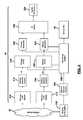
- FIG. 1is an overall system view of a collection and communication system in the continental United States.
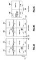
- FIG. 2is a system view at the regional level of the collection and communication system.
- FIG. 3is a detailed block diagrammatic view of a local collection facility illustrated in FIGS. 1 and 2 .
- FIG. 4is a detailed block diagrammatic view of a remote uplink facility.
- FIG. 5is a block diagrammatic view of a monitoring system of FIG. 3 .
- FIG. 6Ais a plan view of a local collection receiver monitoring display.
- FIG. 6Bis a plan view of an uplink monitoring display.
- FIG. 6Cis a plan view of a thread monitoring display.
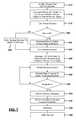
- FIG. 7is a flowchart illustrating a method for controlling a back-up receiver decoder circuit module at the local collection facility from a remote facility.
- FIG. 8is a flowchart of a method for switching to a back-up multiplexer at the local collection facility from a remote facility.
- FIG. 9is of a method for switching to a back-up network adapter at the local collection facility from a remote facility.
- module, circuit and/or devicerefers to an Application Specific Integrated Circuit (ASIC), an electronic circuit, a processor (shared, dedicated, or group) and memory that execute one or more software or firmware programs, a combinational logic circuit, and/or other suitable components that provide the described functionality.
- ASICApplication Specific Integrated Circuit
- processorshared, dedicated, or group
- memorythat execute one or more software or firmware programs, a combinational logic circuit, and/or other suitable components that provide the described functionality.
- the phrase at least one of A, B, and Cshould be construed to mean a logical (A or B or C), using a non-exclusive logical or. It should be understood that steps within a method may be executed in different order without altering the principles of the present disclosure.
- the present disclosureis described with respect to a satellite television system. However, the present disclosure may have various uses including satellite data transmission and reception for home or business uses.
- the systemmay also be used in a cable system or wireless terrestrial communication system.
- a collection and communication system 10includes a satellite 12 that includes at least one transponder 13 .
- a satellite 12that includes at least one transponder 13 .
- multiple transpondersare in a satellite. Although only one satellite is shown, more than one is possible or even likely.
- the collection and communication system 10includes a central facility or Network operations center (NOC) 14 and a plurality of regional or remote uplink facilities (RUF) 16 A, 16 B, 16 C, 16 D, 16 E and 16 F.
- NOCNetwork operations center
- REFregional or remote uplink facilities
- the regional or remote uplink facilities 16 A- 16 Fmay be located at various locations throughout a landmass 18 such as the continental United States, including more or less than those illustrated.
- the regional or remote uplink facilities 16 A- 16 Fuplink various uplink signals 17 to satellite 12 .
- the satellitesdownlink signals 19 to various users 20 that may be located in different areas of the landmass 18 .
- the users 20may be mobile or fixed users.
- the uplink signals 17may be digital signals such as digital television signals or digital data signals.
- the digital television signalsmay be high definition television signals, standard definition signals or combinations of both. Uplinking may be performed at various frequencies including Ka band. The present disclosure, however, is not limited to Ka band. However, Ka band is a suitable frequency example used throughout this disclosure.
- the central facility or NOC 14may also receive downlink signals 19 corresponding to the uplink signals 17 from the various regional or remote uplink facilities and from itself for monitoring purposes. The central facility 14 may monitor and control the quality of all the signals broadcast from the system 10 .
- the central facility 14may also be coupled to the regional or remote uplink facilities through a network such as a computer network having associated communication lines 24 A- 24 F.
- Each communication line 24 A-Fis associated with a respective regional or remote uplink site 16 .
- Communication lines 24 A- 24 Fare terrestrial-based lines.
- all of the functions performed at the regional or remote uplink facilitiesmay be controlled centrally at the central facility 14 as long as the associated communication line 24 A-F is not interrupted.
- each regional or remote uplink site 16 A-Fmay operate autonomously so that uplink signals may continually be provided to the satellite 12 .
- Each of the regional or remote uplink and central facilitiesincludes a transmitting and receiving antenna which is not shown for simplicity in FIG. 1 .
- Each of the regional or remote uplink facilities 16 A- 16 Fmay also be in communication with a local collection facility collectively referred to with reference numeral 30 .
- a local collection facilitycollectively referred to with reference numeral 30 .
- three local collection facilitiesare associated with each remote uplink facility 16 .
- remote uplink facility 16 Ahas local collection facilities 30 A, 30 B and 30 C associated therewith.
- Local collection facilities 30 D- 30 Sare associated with one of the other remote uplink facilities 16 B- 16 F.
- the number of local collection facilities 30may be numerous, such as 40 for each remote uplink facility.
- the number of local collection facilities 30is limited by the amount of equipment and the capabilities thereof associated with each remote uplink facility 16 .
- the local collection facilities 30are used for collecting local television stations in various designated marketing areas (DMA). As is illustrated, local collection facility 30 A is located in DMA 1 and local collection facility 30 B is located in DMA 2 . For simplicity, only two DMAs are illustrated. However, each local collection facility may be located in a DMA.
- DMAdesignated marketing areas
- the local collection facilities 30may be in communication with each remote uplink facility 16 through a communication network 32 .
- the communication network 32may be an internet protocol (IP) network.
- IPinternet protocol
- the signals from the local collection facilities 30may thus be video-over-IP signals.
- Each of the remote uplink facilities 16are in communication with each local collection facility 30 through the communication network 32 .
- local collection facility 30 Ais in communication with the remote uplink facility 16 A through communication network 32 A
- local collection facility 30 Bis in communication with the remote uplink facility 16 A through communication network 32 B, and so on.
- the regional or remote uplink facilities 16 A- 16 F of FIG. 1are illustrated collectively as reference numeral 16 .
- the regional facilities 16may actually comprise two facilities that include a primary site 40 (such as the remote uplink facility 16 above) and a diverse site 42 .
- the primary site 40may be referred to as a primary broadcast center (PBC).
- the central site 14may also include a primary site and diverse site as is set forth herein.
- the primary site 40 and diverse site 42 of both the central and regional sitesmay be separated by at least 25 miles, or, more even more such as, at least 40 miles. In one constructed embodiment, 50 miles was used,
- the primary site 40includes a first antenna 44 for transmitting and receiving signals to and from satellite 12 .
- Diverse site 42also includes an antenna 46 for transmitting and receiving signals from satellite 12 .
- Primary site 40 and diverse site 42may also receive signals from GPS satellites 50 .
- GPS satellites 50generate signals corresponding to the location and a precision timed signal that may be provided to the primary site 40 through an antenna 52 and to the diverse site 42 through an antenna 54 .
- redundant GPS antennas ( 52 A,B) for each sitemay be provided.
- antennas 44 and 46may also be used to receive GPS signals.
- a precision time source 56may also be coupled to the primary site 40 and to the diverse site 42 for providing a precision time source.
- the precision time source 56may include various sources such as coupling to a central atomic clock.
- the precision time source 56may be used to trigger certain events such as advertising insertions and the like.
- the primary site 40 and the diverse site 42may be coupled through a communication line 60 .
- Communication line 60may be a dedicated communication line.
- the primary site 40 and the diverse site 42may communicate over the communication line using a video-over-Internet protocol (IP).
- IPvideo-over-Internet protocol
- Various signal sources 64such as an optical fiber line, copper line or antennas may provide incoming signals 66 to the local collection facility 30 .
- Incoming signal 66may be television signals.
- the television signalsmay be over-the-air high-definition signals, over-the-air standard television signals, or high or standard definition signals received through a terrestrial communication line.
- the incoming signals 66such as the television signals may be routed from the local collection facility 30 through the communication network 30 to the primary site 40 , or the diverse site 42 in the event of a switchover.
- the switchovermay be manual or a weather-related automatic switchover.
- a manual switchoverfor example, may be used during a maintenance condition.
- Users 20receive downlink signals 70 corresponding to the television signals.
- Users 20may include home-based systems, business-based systems or multiple dwelling unit systems.
- a user 20has a receiving antenna 72 coupled to an integrated receiver decoder (IRD) 74 that processes the signals and generates audio and video signals corresponding to the received downlink signal 70 for display on the television or monitor 76 .
- IRDintegrated receiver decoder
- satellite radio receiving systemsmay also be used in place of the IRD 74 .
- the integrated receiver decoder 74may be incorporated into or may be referred to as a set top box.
- the user 20may also be a mobile user.
- the user 20may therefore be implemented in a mobile device or portable device 80 .
- the portable device 80may include but are not limited to various types of devices such as a laptop computer 82 , a personal digital assistant 84 , a cellular telephone 86 or a portable media player 88 .
- the local collection facility 30is illustrated in more detail adjacent to the remote uplink facility (RUF) 16 .
- REFremote uplink facility
- several remote facilitiesmar directed to one remote uplink facility.
- Several remote plink facilitiesmay be located across the country.
- the local collection facility 30is in communication with the remote uplink facility 16 through a network 32 such as an ATM network.
- the local collection facility 30is used for collecting signals in a designated marketing area or other area.
- the channel signalsmay be received as over-the-air television signals or through a direct local feed such as an optical fiber or wire.
- an antenna or plurality of antennas 100are provided for an over-the-air signal.
- the antenna channel signalsare directed to splitters 102 .
- the splitter signalsare communicated to a plurality of receiver circuit modules 104 A-D (collectively referred to as 104 ).
- the number of receiver circuit modules 104depends upon various design parameters such as how many channels the designated market includes. Various numbers of receiver circuit modules 104 may be provided.
- a back-up receiver circuit module 106may also be coupled to the splitters 102 .
- a monitor receiver circuit module 108may be included at the local collection facility 108 .
- the receiver circuit modules generally 104 , 106 and 108include a tuner module 110 and a decoder module 112 .
- the receiver circuit module 104is used to tune, demodulate and decode the over-the-air signals.
- the tunermay be fixed-tuned to a particular channel or may be adjustable.
- the receiver circuit modules 104 A-Dare suitable for fixed tuning.
- the back-up receiver module 106 and monitor receiver circuit module 108are particularly suited for multi-channel tuning.
- the receiver circuit modulesas will be described below may include an ATSC receiver or an NTSC receiver. In ATSC form the receiver receives an MPEG2 signal.
- the decodingmay thus be MPEG2 decoding.
- the receiver circuit modules 104may generate a high definition serial digital interface signal (HD SDI) and an asynchronous serial interface (ASI) signal.
- HD SDIhigh definition serial digital interface signal
- ASIasynchronous serial interface
- the back-up receiver circuit module 106 and the monitor receiver module 108may be in communication with an antenna switch 114 .
- the antenna switch 114is in communication with the splitters 102 which are in communication with the antennas 100 .
- the antenna switch 114may be used to communicate the output of a particular antenna to the back-up receiver decoder 106 and the monitor receiver decoder 108 .
- the back-up receiver decoder 106may also generate both an HD SDI signal and an ASI signal.
- the monitor receiver module 108may be used to generate only an ASI signal.
- a serial digital interface router 120may also be provided.
- the serial digital interface router 120may be a high definition serial digital interface router.
- the router 120may receive local feeds 118 directly from the local channel providers.
- the feedsmay also be in MPEG2 format. These may be provided through a wire or optical fiber.
- the router 120routes the channel signals received from the local feeds 118 to the receiver circuit modules 104 , 106 , 108 where received signals are decoded from MPEG2 format.
- the received signalsare processed and encoded into a format such an MPEG4 format in the encoders 124 A-D.
- a back-up encoder 126 associated with the backup receiver decodermay also be provided.
- the output of the encoders 124 A-D, 126are in communication with a primary multiplexer 128 and a back-up multiplexer 130 .
- the primary multiplexer 128 an the back-up multiplexer 130multiplex the encoded signals and provide them to a primary network adapter 132 and a back-up network adapter 134 .
- Both the primary network adapter 132 and the back-up network adapter 134may be in communication with the primary multiplexer 128 and the back-up multiplexer 130 .
- the network adapters 132 , 134receive the multiplexed signals and format them into an asynchronous transfer mode (ATM) configuration.
- ATM configurationtypically includes cells of a fixed size with a header of 5 bytes and a payload of 48 bytes.
- the headermay include a generic flow control field, a virtual path identifier, a virtual channel identifier, a payload type, a cell loss priority, and a header error control.
- the local collection facility 30may also include a monitoring integrated receiver decoder (MIRD) 140 .
- the output of the monitoring IRD 140may be provided to an MIRD encoder 142 .
- the IRD 140may also be referred to as a set top box.
- the monitoring IRD 140receives downlinked satellite signals and converts these signals to a decoded signal (HD SDI, for example).
- the MIRD encoder 142encodes the signals in a format such as MPEG 4 format.
- the output of the monitor IRD encoder 142may be provided to an ASI router 144 .
- the ASI router 144may route input signals from the decoders 104 A-D, the back-up receiver decoder 106 , the monitor receiver decoder 108 and the monitoring IRD encoder 142 .
- the signalsare routed through the router 144 for monitoring at a monitoring system, as will be described below.
- the monitoring systemmay also control the devices mentioned above through the router 144 . Controlling may be switching to a backup.
- the monitoring systemmay also be in communication with the encoder 124 A-D and 126 , the multiplexers 128 , 130 and the ATM switches 136 - 148 .
- the output of the routeris provided to a monitor network adapter 146 and a primary monitor ATM switch 148 .
- the monitor network adapter 146adapts the signal to the ATM format.
- the ATM formatsignals provided to the primary monitor ATM switch 148 which in turn communicates through the ATM backhaul 32 .
- the remote uplink facility 16may include a primary ATM switch 210 and a back-up ATM switch 212 in communication with the ATM backhaul 32 .
- the primary ATM switch 210 and the back-up ATM switch 212are in communication through the ATM backhaul 32 with the primary ATM switch 136 and the back-up ATM switch 138 .
- the primary ATM switch 210is in communication with a primary network adapter 214 .
- the back-up ATM switch 212is in communication with a back-up network adapter 216 .
- the network adapters 214 and 216are used to generate an ASI signal that is communicated to a respective primary advanced transport processing system (ATPS) 218 and a back-up advanced transport processing system (ATPS) 220 .
- the advanced transport processing systems 218 , 220convert the ASI signals from the network adapters into an advanced transport stream such as a DIRECTV® A3 transport stream.
- the ATPS 218 , 220may act as an encryption module for inserting encryption into the transport stream.
- a primary modulator 222 and a back-up modulator 224receive the transport stream from the respective primary ATPS 218 or the back-up ATPS 220 .
- the primary modulator 222 and the back-up modulator 224modulate the transport stream and generate an RF signal at a frequency such as an L-band frequency.
- An RF switch 226may be referred to as an intermediate frequency switch 226 .
- the RF switchprovides one output signal to the uplink RF system 228 .
- the uplink signalmay then be communicated to the satellite 12 of FIG. 1 . Should the system not be a satellite system, the signal may be communicated terrestrially through a distribution system in a wired or wireless manner.
- Several circuits 210 - 226may be included in a remote facility 16 , each one corresponding to one transponder on the satellite.
- a monitoring system 230may be in communication with a monitor ATM switch 232 and a monitor network adapter 234 for communicating with the various local collection facilities.
- the monitoring system 230may be in communication with the primary ATPS 218 , the back-up ATPS 220 , the primary modulator 222 and the back-up modulator 224 .
- the monitoring system 230may be in communication with the router 144 illustrated in FIG. 3 .
- the router 144may be in communication with the monitor receiver circuit module 108 , the monitor IRD encoder 142 and each of the receiver circuit modules 104 , 106 .
- the monitoring system 230may be referred to as an advanced broadcast monitoring system 230 .
- multiple local collection facilities 30may be coupled to a remote collection facility 16 .
- the diverse uplink facility or diverse site 54 illustrated in FIG. 4may include a primary and back-up ATPS, a modulator and RF switch.
- the monitoring systemmay control the signals to the diverse site 42 .
- the monitoring systemreceives signals through the network 32 .
- feeds from various uplink systemssuch as various IF switches 226 , may be provided to an L-band router 300 .
- An ASI router 302may be used to route the signals from the local collection facilities to a decoder 304 .
- the decodermay be an ATSC decoder. Decoder 304 may be optional should the signals already be decoded at the local collection facility.
- the L-band router 300may be in communication with a monitor IRD 306 .
- the output of the monitor IRD 306 and the decoders 304are provided to a multi-viewer or plurality of multi-viewers 308 .
- a remote uplink facility monitor router 310is used to provide signals to the monitor network encoders 312 which in turn provide signals to a monitor feed network 314 .
- the L-band routersmay also provide signals to a demodulator 316 .
- the output of the demodulator 316 and the monitor network encoders 312may be provided to the monitor feed network 314 .
- the monitor feed network 314may be various types of transmission means used to communicate between the remote uplink facilities 16 and the network operation center 14 .
- the remote uplink facility 16may generate monitoring display 350 as well.
- the monitoring displays 350may also be used to control the various functions at the local collection facilities.
- the monitoring displaysmay be in communication with the monitor router 310 .
- the network operation center 14may include an ASI router 330 for the selection of signals from a particular remote uplink facility.
- the ASI signalsmay be routed to an ATSC decoder 332 and a monitor IRD 334 .
- the ATSC decoder 332may provide the signals to a monitor router 336 .
- a monitor wall 338may be used to generate monitoring signals for use at the network operation center.
- a workstation 340may also receive the signals from the network operation center monitor router 336 .
- the ATSC decoders 332 and the monitor IRDs 334may provide the signals to a quality assurance (QA) room 342 . Screen displays at the monitor wall 338 , the workstation 340 and the quality assurance room 342 are used for monitoring the various remote uplink facilities.
- the workstation 340may also be used for control purposes. Signals are provided to the remote uplink facility and ultimately to the local collection facilities should a problem arise with the signals. Ultimately the control signals may be communicated back through the network 32 .
- the network operation center 14may also include multiple workstations 340 as well as a large monitor wall 338 .
- the workstations 340may have access to various control surfaces that can configure the monitor walls 338 as well as signals fed to the various monitors at the station.
- Control of the on-air failure recovery devices as well as the monitoring functions for every LCF and RUFare accomplished through control surfaces such as touch screens and keyboards together with a GUI at the workstations 340 in the network operation center 14 .
- the control surfacesmay be application-specific and present the status and control options for various multiple configurations for the application.
- the quality assurance room 342may not have any control functions therein.
- the monitors 350may be coupled to the monitor network encoders 315 for displaying various views from the remote uplink facility and the local collection facilities.
- an ATM switch and network adaptermay be provided prior to the ASI router 330 .
- the decoders 332may be MPEG decoders since the signal may be in MPEG form when received from the remote uplink facility.
- a local collection facility monitoris generated having four local collection facility channels 410 , 412 , 414 , and 416 .
- Each displaymay also include an under-monitor display 418 used to identify the particular channel signal.
- the under-monitor displays 418may display the actual channel number, the station identification or other information and the like.
- an uplink monitoris illustrated having an uplink channel one 420 , an uplink channel two 422 , an uplink channel three 424 , and an uplink channel four 426 .
- An under-monitor display 428may also be included with each of the displays 420 - 426 .
- the uplink channelsreceive the uplink channel signals so that they may be monitored.
- the uplink channel signalsprovide an indication as to the uplink channel.
- Various selectionsmay be made for the particular uplink channels for the particular remote uplink facilities.
- FIG. 6Cincludes an uplink channel signal 440 and a local collection facility IRD signal 442 .
- the local collection facility IRD signal 442may be received through the monitoring IRE located at the local collection facility. This is illustrated in FIG. 3 as reference numeral 140 .
- the displaymay also display a channel from the local collection facility, the back-up receiver channel or the local collection facility monitor receiver. Both displays 440 and 442 may include an under-monitor display 450 .
- the monitoring system 230identifies a channel and a local collection facility associated with the channel. This may be performed at a broadcast operation center channel or the like. This may also be performed at the network operation center 14 .
- the channelmay be identified by using the various monitors at the network operation center or the remote uplink facility as described above.
- the methodincludes commanding the monitor ASI router 302 of FIG. 5 to switch to the router input corresponding to the designated LCF monitor network adapter output to the ASI router output defined for the requesting console thread decoder input.
- the thread decodermay then be tuned to the station identification defined for the local channel source for the broadcast operation center in step 516 .
- the antenna switch 144 of FIG. 3is commanded to feed the back-up receiver and the back-up receiver module 108 is tuned in step 522 . It should be noted that the back-up receiver may be tunable, whereas the other receivers in the receiver circuit modules 104 may be fixed-tuned.
- the back-up receiver moduleis switched to the particular ASI input. After step 524 , the back-up receiver is tuned in step 522 .
- step 526the local collection facility ASI router is commanded to switch to the back-up receiver input to monitor the channel feed output at the network adapter.
- step 528a preview of the back-up signals is provided at the remote uplink facility. As mentioned above, the signal may also be provided to the network operation center.
- step 530other channels are prevented to switch to the back-up receiver.
- step 532if the signal is not acceptable a preview is continued in step 528 .
- step 532if the previewed signal is acceptable a switch to the back-up receiver is performed in step 534 .
- the monitoring systemcommands the system to mirror and switch to the back-up encoder if available. Mirroring means communicating any of the set-up configuration parameters from the receiver circuit module in question to the backup receiver circuit module.
- step 538if verification is received that the back-up encoder has been employed in the broadcast signal.
- step 540a notification is provided to the operation that a successful transition to the back-up encoder is provided.
- a method for switching to a back-up multiplexeris set forth.
- step 610a channel is identified and the local collection facility for the channel is identified at either the remote uplink facility or the network operation center.
- step 612a compression system and monitoring system is used associated with the channel is identified.
- step 614if a back-up multiplexer is not available the system ends in step 615 .
- step 614if a back-up multiplexer is available a command is communicated to the monitoring system controller.
- step 618a switch to the back-up multiplexer is generated while the primary multiplexer is disabled.
- step 620a verification is provided to the operator that a successful switch to the multiplexer has been provided.
- step 622a notification is provided to the operator that a successful switch to the back-up multiplexer is provided.
- a method for switching to a network adapteris provided.
- a primary ATM circuitis formed between the local collection facility and the remote uplink facility.
- the local collection facilityis identified.
- the ATM circuit associated with the local collection facilityis also identified.
- step 716the primary ATM circuit for the LCF to RUF connection is torn down.
- step 718a new ATM circuit from the back-up network adapter is created.
- step 720a verification may be provided to the network operator that a successful switch from the primary network adapter to the back-up network adapter has been performed by creating and tearing down a new ATM circuit and the primary ATM circuit.
- step 720a verification may be generated.
- step 722the operator of the system may be notified.
Landscapes
- Engineering & Computer Science (AREA)
- Signal Processing (AREA)
- Physics & Mathematics (AREA)
- Astronomy & Astrophysics (AREA)
- General Physics & Mathematics (AREA)
- Multimedia (AREA)
- Two-Way Televisions, Distribution Of Moving Picture Or The Like (AREA)
Abstract
Description
Claims (19)
Priority Applications (1)
| Application Number | Priority Date | Filing Date | Title |
|---|---|---|---|
| US11/854,408US7861270B2 (en) | 2007-09-12 | 2007-09-12 | Method and system for controlling a back-up receiver and encoder in a local collection facility from a remote facility |
Applications Claiming Priority (1)
| Application Number | Priority Date | Filing Date | Title |
|---|---|---|---|
| US11/854,408US7861270B2 (en) | 2007-09-12 | 2007-09-12 | Method and system for controlling a back-up receiver and encoder in a local collection facility from a remote facility |
Publications (2)
| Publication Number | Publication Date |
|---|---|
| US20090066848A1 US20090066848A1 (en) | 2009-03-12 |
| US7861270B2true US7861270B2 (en) | 2010-12-28 |
Family
ID=40431452
Family Applications (1)
| Application Number | Title | Priority Date | Filing Date |
|---|---|---|---|
| US11/854,408Active2028-11-25US7861270B2 (en) | 2007-09-12 | 2007-09-12 | Method and system for controlling a back-up receiver and encoder in a local collection facility from a remote facility |
Country Status (1)
| Country | Link |
|---|---|
| US (1) | US7861270B2 (en) |
Cited By (2)
| Publication number | Priority date | Publication date | Assignee | Title |
|---|---|---|---|---|
| US20080285653A1 (en)* | 2007-05-14 | 2008-11-20 | Himax Technologies Limited | Motion estimation method |
| US9831971B1 (en)* | 2011-04-05 | 2017-11-28 | The Directv Group, Inc. | Method and system for operating a communication system encoded into multiple independently communicated encoding formats |
Families Citing this family (13)
| Publication number | Priority date | Publication date | Assignee | Title |
|---|---|---|---|---|
| US8072874B2 (en) | 2007-09-11 | 2011-12-06 | The Directv Group, Inc. | Method and system for switching to an engineering signal processing system from a production signal processing system |
| US9313457B2 (en) | 2007-09-11 | 2016-04-12 | The Directv Group, Inc. | Method and system for monitoring a receiving circuit module and controlling switching to a back-up receiving circuit module at a local collection facility from a remote facility |
| US8973058B2 (en) | 2007-09-11 | 2015-03-03 | The Directv Group, Inc. | Method and system for monitoring and simultaneously displaying a plurality of signal channels in a communication system |
| US8170069B2 (en) | 2007-09-11 | 2012-05-01 | The Directv Group, Inc. | Method and system for processing signals from a local collection facility at a signal processing facility |
| US8356321B2 (en)* | 2007-09-11 | 2013-01-15 | The Directv Group, Inc. | Method and system for monitoring and controlling receiving circuit modules at a local collection facility from a remote facility |
| US8479234B2 (en)* | 2007-09-12 | 2013-07-02 | The Directv Group, Inc. | Method and system for monitoring and controlling a local collection facility from a remote facility using an asynchronous transfer mode (ATM) network |
| US8988986B2 (en) | 2007-09-12 | 2015-03-24 | The Directv Group, Inc. | Method and system for controlling a back-up multiplexer in a local collection facility from a remote facility |
| US9049354B2 (en)* | 2007-10-30 | 2015-06-02 | The Directv Group, Inc. | Method and system for monitoring and controlling a back-up receiver in local collection facility from a remote facility using an IP network |
| US9037074B2 (en)* | 2007-10-30 | 2015-05-19 | The Directv Group, Inc. | Method and system for monitoring and controlling a local collection facility from a remote facility through an IP network |
| US8077706B2 (en)* | 2007-10-31 | 2011-12-13 | The Directv Group, Inc. | Method and system for controlling redundancy of individual components of a remote facility system |
| US9049037B2 (en)* | 2007-10-31 | 2015-06-02 | The Directv Group, Inc. | Method and system for monitoring and encoding signals in a local facility and communicating the signals between a local collection facility and a remote facility using an IP network |
| US9762973B2 (en) | 2008-11-04 | 2017-09-12 | The Directv Group, Inc. | Method and system for operating a receiving circuit module to encode a channel signal into multiple encoding formats |
| CN104683661A (en)* | 2015-03-10 | 2015-06-03 | 上海数虎图像科技有限公司 | Special multimedia host system for stages |
Citations (106)
| Publication number | Priority date | Publication date | Assignee | Title |
|---|---|---|---|---|
| US4317010A (en) | 1978-12-22 | 1982-02-23 | Fillot Jean Jacques Y | Remote monitoring system for remote locating and gain regulating of amplification circuits in data transmission line |
| US4984252A (en) | 1987-11-10 | 1991-01-08 | Nec Corporation | Channel switching system |
| US5323322A (en)* | 1992-03-05 | 1994-06-21 | Trimble Navigation Limited | Networked differential GPS system |
| US5351130A (en)* | 1993-01-28 | 1994-09-27 | Houston Satellite Systems, Inc. | Satellite receiver with improved memory back-up and loading capabilities |
| US5566353A (en) | 1994-09-06 | 1996-10-15 | Bylon Company Limited | Point of purchase video distribution system |
| US5583562A (en) | 1993-12-03 | 1996-12-10 | Scientific-Atlanta, Inc. | System and method for transmitting a plurality of digital services including imaging services |
| US5600573A (en) | 1992-12-09 | 1997-02-04 | Discovery Communications, Inc. | Operations center with video storage for a television program packaging and delivery system |
| US5646675A (en)* | 1989-06-22 | 1997-07-08 | Airtrax | System and method for monitoring video program material |
| US5659350A (en) | 1992-12-09 | 1997-08-19 | Discovery Communications, Inc. | Operations center for a television program packaging and delivery system |
| US5666293A (en) | 1994-05-27 | 1997-09-09 | Bell Atlantic Network Services, Inc. | Downloading operating system software through a broadcast channel |
| US6047162A (en) | 1997-09-25 | 2000-04-04 | Com Dev Limited | Regional programming in a direct broadcast satellite |
| US6154772A (en)* | 1997-11-04 | 2000-11-28 | Georgia Tech Research Corporation | System and method for the delivery of digital video and data over a communication channel |
| US20010003846A1 (en)* | 1999-05-19 | 2001-06-14 | New Horizons Telecasting, Inc. | Encapsulated, streaming media automation and distribution system |
| US20010026537A1 (en) | 2000-02-24 | 2001-10-04 | Michael Massey | Satellite internet backbone network system using virtual onboard switching |
| US6308286B1 (en) | 1994-06-30 | 2001-10-23 | Hughes Electronics Corporation | Complexity reduction system and method for integrated redundancy switchover systems |
| US20010036198A1 (en) | 1996-09-05 | 2001-11-01 | Hughes Electronics Corporation | Dynamic mapping of broadcast resources |
| US20020053049A1 (en) | 1997-12-30 | 2002-05-02 | Shoji Shiomoto | Error correction encoding method and apparatus data transmission method receiving method and receiver |
| US6401242B1 (en)* | 1997-10-24 | 2002-06-04 | General Instrument Corporation | Method and apparatus for designating a preferred source to avoid duplicative programming services |
| US20020105976A1 (en) | 2000-03-10 | 2002-08-08 | Frank Kelly | Method and apparatus for deriving uplink timing from asynchronous traffic across multiple transport streams |
| US20020194596A1 (en) | 2001-06-18 | 2002-12-19 | Srivastava Gopal K. | Control of multiple AV-devices by a single master controller using infrared transmitted commands and bus transmitted commands |
| US6512794B1 (en) | 1998-07-30 | 2003-01-28 | Matsushita Electric Industrial Co., Ltd. | Receiver and transmitter-receiver |
| US20030028897A1 (en) | 2001-08-06 | 2003-02-06 | Brooks Paul D. | Technique for reverse transport of data in a hybrid fiber coax cable system |
| US6529146B1 (en) | 2000-06-09 | 2003-03-04 | Interactive Video Technologies, Inc. | System and method for simultaneously encoding data in multiple formats and at different bit rates |
| US20030088873A1 (en)* | 1997-01-07 | 2003-05-08 | United Video Properties, Inc. | System and method for distributing and broadcasting multimedia |
| WO2003058967A1 (en) | 2001-12-28 | 2003-07-17 | Pegasus Development Corporation | Wideband direct-to-home broadcasting satellite communications system and method |
| US20030161262A1 (en)* | 2002-02-26 | 2003-08-28 | Nec Corporation | High speed switching router using APS and method for switching the same |
| US6625811B1 (en)* | 1997-04-25 | 2003-09-23 | Sony Corporation | Multichannel broadcasting system |
| US20030196211A1 (en)* | 2002-04-10 | 2003-10-16 | Peter Chan | Systems, methods and apparatuses for simulated rapid tuning of digital video channels |
| US6654923B1 (en) | 1999-09-09 | 2003-11-25 | Nortel Networks Limited | ATM group protection switching method and apparatus |
| US20040022275A1 (en) | 2002-08-02 | 2004-02-05 | Blanchard Scott D. | Methods and apparatus for coupling an earth terminal to a satellite |
| US20040022535A1 (en)* | 2002-08-01 | 2004-02-05 | Steve Wang | System and method for preventing signal loss in an optical communications network |
| US6741553B1 (en) | 1999-12-08 | 2004-05-25 | Nortel Networks Limited | Method and system for protecting virtual traffic in a communications network |
| US20040120349A1 (en) | 2002-11-14 | 2004-06-24 | Hughes Electronics | Systems and methods for transmitting internet protocol data via satellite |
| US20040216171A1 (en) | 2001-08-16 | 2004-10-28 | Goldpocket Interactive | Remote monitoring system and method for interactive television data |
| US20040234145A1 (en) | 2003-05-19 | 2004-11-25 | Hitachi, Ltd. | Encoding apparatus, video camera |
| US20040255333A1 (en) | 2001-06-06 | 2004-12-16 | Kevin Kenworthy | Centralized aggregation of broadcast television programming and multi-market digital delivery thereof over interconnected terrestrial fiber optic networks |
| US20050002339A1 (en) | 2003-06-20 | 2005-01-06 | Marconi Communications, Inc. | Distributed protection switching |
| US6873877B1 (en) | 1999-02-11 | 2005-03-29 | Loudeye Corp. | Distributed production system for digitally encoding information |
| US20050076134A1 (en) | 2001-05-17 | 2005-04-07 | Gil Bialik | Apparatus and method for multiple rich media formats video broadcasting |
| US20050099969A1 (en) | 1998-04-03 | 2005-05-12 | Roberts Roswell Iii | Satellite receiver/router, system, and method of use |
| US20050175085A1 (en)* | 2004-01-23 | 2005-08-11 | Sarnoff Corporation | Method and apparatus for providing dentable encoding and encapsulation |
| US20050210133A1 (en) | 2004-03-12 | 2005-09-22 | Danilo Florissi | Method and apparatus for determining monitoring locations in distributed systems |
| US20050240967A1 (en) | 2004-04-27 | 2005-10-27 | Anderson Glen J | System and method for improved channel surfing |
| US20060018254A1 (en)* | 2004-07-26 | 2006-01-26 | John Sanders | Statistical multiplexer having protective features from extraneous messages generated by redundant system elements |
| US20060064726A1 (en) | 2004-09-21 | 2006-03-23 | Loner Patrick J | Method of using feedback from consumer terminals to adaptively control a satellite system |
| US7039937B1 (en)* | 2001-02-28 | 2006-05-02 | Glenn R Bryce | System and method for providing satellite signals to multiple receiving units |
| US20060098735A1 (en) | 2004-11-10 | 2006-05-11 | Yu-Chung Chang | Apparatus for motion estimation using a two-dimensional processing element array and method therefor |
| US20060120327A1 (en) | 2004-11-09 | 2006-06-08 | Samusung Electronics Co., Ltd. | Method for providing multicast service according to handoff of source node in mobile internet protocol communication system |
| US20060126634A1 (en) | 2004-10-06 | 2006-06-15 | Samsung Electronics Co., Ltd. | Method and apparatus of providing and receiving video services in digital audio broadcasting (DAB) system |
| US7072365B1 (en)* | 2000-12-29 | 2006-07-04 | Arris Interactive, Llc | System and method for multiplexing broadband signals |
| US20060166699A1 (en) | 2005-01-21 | 2006-07-27 | King's College London | Method of discovering multi-mode mobile terminals |
| US20060198389A1 (en) | 2005-03-01 | 2006-09-07 | Eriokson Michael J | Multi-drop ethernet |
| US20070002851A1 (en) | 2005-06-30 | 2007-01-04 | Toni Paila | Transmission and reception of session packets |
| US20070040933A1 (en) | 2005-07-22 | 2007-02-22 | Aircode Co., Ltd. | Transport stream reprocessing device and data broadcasting system using the device |
| US20070053379A1 (en) | 2005-09-06 | 2007-03-08 | Mark Hershey | Streaming media encoder with confidence monitor |
| US20070091857A1 (en) | 2005-10-24 | 2007-04-26 | General Instrument Corporation | Method and apparatus for generating multiplexed signals |
| US7212738B1 (en)* | 2002-08-01 | 2007-05-01 | Finisar Corporation | Preventing signal loss in an optical communications network |
| US7219367B2 (en)* | 2002-09-09 | 2007-05-15 | Scientific-Atlanta, Inc. | Backup communication modes |
| US20070118861A1 (en) | 2005-11-21 | 2007-05-24 | General Instrument Corporation | System and method for delivering graphics received through a cable television system to a digital television |
| US7224837B2 (en)* | 2000-10-11 | 2007-05-29 | Screenpeaks Ltd. | Digital video broadcasting |
| US20070136765A1 (en)* | 2005-12-13 | 2007-06-14 | The Directv Group, Inc. | Multiple dwelling unit satellite television delivery system |
| US20070136777A1 (en)* | 2005-12-09 | 2007-06-14 | Charles Hasek | Caption data delivery apparatus and methods |
| US20070162927A1 (en)* | 2004-07-23 | 2007-07-12 | Arun Ramaswamy | Methods and apparatus for monitoring the insertion of local media content into a program stream |
| US20070186251A1 (en)* | 2006-02-03 | 2007-08-09 | Horowitz Edward D | Emergency satellite network |
| US20070204311A1 (en)* | 2006-02-27 | 2007-08-30 | Hasek Charles A | Methods and apparatus for selecting digital coding/decoding technology for programming and data delivery |
| US20070204300A1 (en)* | 2006-02-27 | 2007-08-30 | Markley Jeffrey P | Methods and apparatus for selecting digital interface technology for programming and data delivery |
| US20070261073A1 (en) | 2006-04-25 | 2007-11-08 | Xorbit, Inc. | System and method for monitoring video data |
| US20070263627A1 (en) | 2001-01-26 | 2007-11-15 | Nec Corporation | Method and system for controlling communication network and router used in the network |
| US20070268817A1 (en)* | 2006-05-22 | 2007-11-22 | Nortel Networks Limited | Method and system for protecting a sub-domain within a broadcast domain |
| US7302224B2 (en)* | 2000-05-03 | 2007-11-27 | The Directv Group, Inc. | Communication system for rebroadcasting electronic content within local area network |
| US7315887B1 (en) | 2001-04-11 | 2008-01-01 | Alcatel Lucent | Facilitating integration of communications network equipment inventory management |
| US7333425B2 (en) | 2002-11-19 | 2008-02-19 | Alcatel | Failure localization in a transmission network |
| US7346918B2 (en) | 2000-12-27 | 2008-03-18 | Z-Band, Inc. | Intelligent device system and method for distribution of digital signals on a wideband signal distribution system |
| US20080069155A1 (en)* | 2006-09-14 | 2008-03-20 | Tandberg Television Inc. | Systems and methods for analog channel reuse in a cable system |
| US20080102750A1 (en) | 2006-11-01 | 2008-05-01 | Keener David J | Broadcast method and system |
| US20080137543A1 (en) | 2006-12-12 | 2008-06-12 | Cisco Technology, Inc. | Remote testing of an electronic device via network connection |
| US20080201748A1 (en)* | 2006-02-27 | 2008-08-21 | Hasek Charles A | Methods and apparatus for device capabilities discovery and utilization within a content-based network |
| US20080282011A1 (en) | 2007-05-09 | 2008-11-13 | Arcadyan Technology Corporation | Remote control system and method thereof |
| US20080291907A1 (en) | 2004-06-14 | 2008-11-27 | Siemens Aktiengesellschaft | Data-Transmission Device and Method for Transmitting Data with a Reduced Outage Risk |
| US7460832B2 (en)* | 2004-04-12 | 2008-12-02 | The Directv Group, Inc. | Methods and apparatuses for minimizing co-channel interference |
| US20090025027A1 (en) | 2007-07-20 | 2009-01-22 | Michael Craner | Systems & methods for allocating bandwidth in switched digital video systems based on interest |
| US20090022241A1 (en) | 2005-01-21 | 2009-01-22 | Matsushita Electric Industrial Co., Ltd. | Wireless communication apparatus and wireless communication method |
| US7493648B2 (en) | 2000-04-11 | 2009-02-17 | Sony Corporation | Data transmission device, data receiving device, data transmitting method, data receiving method, recording device, playback device, recording method, and playback method |
| US20090052323A1 (en) | 2005-03-21 | 2009-02-26 | Dirk Breynaert | Managing Traffic in a Satellite Transmission System |
| US20090067433A1 (en) | 2007-09-12 | 2009-03-12 | The Directv Group, Inc. | Method and system for controlling a back-up network adapter in a local collection facility from a remote facility |
| US20090069021A1 (en) | 2007-09-11 | 2009-03-12 | The Directv Group, Inc. | Method and System for Monitoring and Switching Between a First Uplink Signal Processing Circuit and a Second Uplink Signal Processing Circuit |
| US20090070824A1 (en) | 2007-09-11 | 2009-03-12 | The Directv Group, Inc. | Method and System for Monitoring and Switching Between Primary and Back-up Uplink Signal Processing Circuits in a Satellite Communication System |
| US20090070825A1 (en) | 2007-09-11 | 2009-03-12 | The Directv Group, Inc. | Method and System for Monitoring and Controlling Receiving Circuit Modules at a Local Collection Facility From a Remote Facility |
| US20090067490A1 (en) | 2007-09-11 | 2009-03-12 | The Directv Group, Inc. | Method and system for monitoring and switching between a primary encoder and a back-up encoder in a communication system |
| US20090070830A1 (en) | 2007-09-11 | 2009-03-12 | The Directv Group, Inc. | Method and System for Monitoring a Receiving Circuit Module and Controlling Switching to a Back-up Receiving Circuit Module at a Local Collection Facility from a Remote Facility |
| US20090067365A1 (en) | 2007-09-11 | 2009-03-12 | The Directv Group, Inc. | Method and System for Switching to an Engineering Signal Processing System from a Production Signal Processing System |
| US20090067432A1 (en) | 2007-09-12 | 2009-03-12 | The Directv Group, Inc. | Method and system for controlling a back-up multiplexer in a local collection facility from a remote facility |
| US20090070846A1 (en) | 2007-09-12 | 2009-03-12 | The Directv Group, Inc. | Method and system for monitoring and controlling a local collection facility from a remote facility using an asynchronous transfer mode (atm) network |
| US7525993B2 (en) | 2006-05-24 | 2009-04-28 | Newport Media, Inc. | Robust transmission system and method for mobile television applications |
| US20090113490A1 (en) | 2007-10-30 | 2009-04-30 | Wasden Mitchell B | Method and system for monitoring and controlling a local collection facility from a remote facility through an ip network |
| US20090109883A1 (en) | 2007-10-31 | 2009-04-30 | Wasden Mitchell B | Method and system for monitoring and encoding signals in a local facility and communicating the signals between a local collection facility and a remote facility using an ip network |
| US20090109836A1 (en) | 2007-10-31 | 2009-04-30 | Wasden Mitchell B | Method and system for controlling redundancy of individual components of a remote facility system |
| US20090110052A1 (en) | 2007-10-30 | 2009-04-30 | Wasden Mitchell B | Method and system for monitoring and controlling a back-up receiver in local collection facility from a remote facility using an ip network |
| US7529276B1 (en) | 2002-09-03 | 2009-05-05 | Cisco Technology, Inc. | Combined jitter and multiplexing systems and methods |
| US20090213814A1 (en) | 2003-08-20 | 2009-08-27 | Samsung Electronics Co., Ltd. | Method and apparatus for providing uplink packet data service in asynchronous wcdma system |
| US7596350B1 (en)* | 2006-09-29 | 2009-09-29 | The Directv Group, Inc. | Method and system for determining delays between a primary site and diverse site in a satellite communication system |
| US7607154B2 (en) | 2002-10-04 | 2009-10-20 | Rai Radiotelevisione Italiana S.P.A. | System for the transmission of DVB/MPEG digital signals, particularly for satellite communication |
| US7650620B2 (en) | 1998-03-06 | 2010-01-19 | Laurence A Fish | Method and apparatus for push and pull distribution of multimedia |
| US20100020887A1 (en) | 2002-09-30 | 2010-01-28 | Broadcom Corporation, A California Corporation | Multiple time-base clock for processing multiple satellite signals |
| US7746791B2 (en) | 2005-08-24 | 2010-06-29 | Abb Technology Ag | Monitoring an industrial communication network |
| US20100208595A1 (en) | 2007-10-09 | 2010-08-19 | Wei Zhao | Arrangement and a method for handling failures in a network |
Family Cites Families (1)
| Publication number | Priority date | Publication date | Assignee | Title |
|---|---|---|---|---|
| US7031393B2 (en)* | 2000-10-20 | 2006-04-18 | Matsushita Electric Industrial Co., Ltd. | Block distortion detection method, block distortion detection apparatus, block distortion removal method, and block distortion removal apparatus |
- 2007
- 2007-09-12USUS11/854,408patent/US7861270B2/enactiveActive
Patent Citations (110)
| Publication number | Priority date | Publication date | Assignee | Title |
|---|---|---|---|---|
| US4317010A (en) | 1978-12-22 | 1982-02-23 | Fillot Jean Jacques Y | Remote monitoring system for remote locating and gain regulating of amplification circuits in data transmission line |
| US4984252A (en) | 1987-11-10 | 1991-01-08 | Nec Corporation | Channel switching system |
| US5155483A (en) | 1987-11-10 | 1992-10-13 | Nec Corporation | Channel switching system |
| US5646675A (en)* | 1989-06-22 | 1997-07-08 | Airtrax | System and method for monitoring video program material |
| US5323322A (en)* | 1992-03-05 | 1994-06-21 | Trimble Navigation Limited | Networked differential GPS system |
| US5659350A (en) | 1992-12-09 | 1997-08-19 | Discovery Communications, Inc. | Operations center for a television program packaging and delivery system |
| US5600573A (en) | 1992-12-09 | 1997-02-04 | Discovery Communications, Inc. | Operations center with video storage for a television program packaging and delivery system |
| US20090254962A1 (en) | 1992-12-09 | 2009-10-08 | Comcast Ip Holdings I, Llc | Operations center for a television program packaging and delivery system |
| US5351130A (en)* | 1993-01-28 | 1994-09-27 | Houston Satellite Systems, Inc. | Satellite receiver with improved memory back-up and loading capabilities |
| US5583562A (en) | 1993-12-03 | 1996-12-10 | Scientific-Atlanta, Inc. | System and method for transmitting a plurality of digital services including imaging services |
| US5666293A (en) | 1994-05-27 | 1997-09-09 | Bell Atlantic Network Services, Inc. | Downloading operating system software through a broadcast channel |
| US6308286B1 (en) | 1994-06-30 | 2001-10-23 | Hughes Electronics Corporation | Complexity reduction system and method for integrated redundancy switchover systems |
| US5566353A (en) | 1994-09-06 | 1996-10-15 | Bylon Company Limited | Point of purchase video distribution system |
| US20010036198A1 (en) | 1996-09-05 | 2001-11-01 | Hughes Electronics Corporation | Dynamic mapping of broadcast resources |
| US20030088873A1 (en)* | 1997-01-07 | 2003-05-08 | United Video Properties, Inc. | System and method for distributing and broadcasting multimedia |
| US6625811B1 (en)* | 1997-04-25 | 2003-09-23 | Sony Corporation | Multichannel broadcasting system |
| US6047162A (en) | 1997-09-25 | 2000-04-04 | Com Dev Limited | Regional programming in a direct broadcast satellite |
| US6401242B1 (en)* | 1997-10-24 | 2002-06-04 | General Instrument Corporation | Method and apparatus for designating a preferred source to avoid duplicative programming services |
| US6434562B1 (en)* | 1997-11-04 | 2002-08-13 | Georgia Tech Research Corporation | Computer system and method for providing digital video and data over a communication channel |
| US6154772A (en)* | 1997-11-04 | 2000-11-28 | Georgia Tech Research Corporation | System and method for the delivery of digital video and data over a communication channel |
| US20020053049A1 (en) | 1997-12-30 | 2002-05-02 | Shoji Shiomoto | Error correction encoding method and apparatus data transmission method receiving method and receiver |
| US7650620B2 (en) | 1998-03-06 | 2010-01-19 | Laurence A Fish | Method and apparatus for push and pull distribution of multimedia |
| US20050099969A1 (en) | 1998-04-03 | 2005-05-12 | Roberts Roswell Iii | Satellite receiver/router, system, and method of use |
| US6512794B1 (en) | 1998-07-30 | 2003-01-28 | Matsushita Electric Industrial Co., Ltd. | Receiver and transmitter-receiver |
| US6873877B1 (en) | 1999-02-11 | 2005-03-29 | Loudeye Corp. | Distributed production system for digitally encoding information |
| US20010003846A1 (en)* | 1999-05-19 | 2001-06-14 | New Horizons Telecasting, Inc. | Encapsulated, streaming media automation and distribution system |
| US6654923B1 (en) | 1999-09-09 | 2003-11-25 | Nortel Networks Limited | ATM group protection switching method and apparatus |
| US6741553B1 (en) | 1999-12-08 | 2004-05-25 | Nortel Networks Limited | Method and system for protecting virtual traffic in a communications network |
| US20010026537A1 (en) | 2000-02-24 | 2001-10-04 | Michael Massey | Satellite internet backbone network system using virtual onboard switching |
| US20020105976A1 (en) | 2000-03-10 | 2002-08-08 | Frank Kelly | Method and apparatus for deriving uplink timing from asynchronous traffic across multiple transport streams |
| US7493648B2 (en) | 2000-04-11 | 2009-02-17 | Sony Corporation | Data transmission device, data receiving device, data transmitting method, data receiving method, recording device, playback device, recording method, and playback method |
| US7302224B2 (en)* | 2000-05-03 | 2007-11-27 | The Directv Group, Inc. | Communication system for rebroadcasting electronic content within local area network |
| US6529146B1 (en) | 2000-06-09 | 2003-03-04 | Interactive Video Technologies, Inc. | System and method for simultaneously encoding data in multiple formats and at different bit rates |
| US7224837B2 (en)* | 2000-10-11 | 2007-05-29 | Screenpeaks Ltd. | Digital video broadcasting |
| US7346918B2 (en) | 2000-12-27 | 2008-03-18 | Z-Band, Inc. | Intelligent device system and method for distribution of digital signals on a wideband signal distribution system |
| US7072365B1 (en)* | 2000-12-29 | 2006-07-04 | Arris Interactive, Llc | System and method for multiplexing broadband signals |
| US20070263627A1 (en) | 2001-01-26 | 2007-11-15 | Nec Corporation | Method and system for controlling communication network and router used in the network |
| US7039937B1 (en)* | 2001-02-28 | 2006-05-02 | Glenn R Bryce | System and method for providing satellite signals to multiple receiving units |
| US7315887B1 (en) | 2001-04-11 | 2008-01-01 | Alcatel Lucent | Facilitating integration of communications network equipment inventory management |
| US20050076134A1 (en) | 2001-05-17 | 2005-04-07 | Gil Bialik | Apparatus and method for multiple rich media formats video broadcasting |
| US20040255333A1 (en) | 2001-06-06 | 2004-12-16 | Kevin Kenworthy | Centralized aggregation of broadcast television programming and multi-market digital delivery thereof over interconnected terrestrial fiber optic networks |
| US20020194596A1 (en) | 2001-06-18 | 2002-12-19 | Srivastava Gopal K. | Control of multiple AV-devices by a single master controller using infrared transmitted commands and bus transmitted commands |
| US20030028897A1 (en) | 2001-08-06 | 2003-02-06 | Brooks Paul D. | Technique for reverse transport of data in a hybrid fiber coax cable system |
| US20040216171A1 (en) | 2001-08-16 | 2004-10-28 | Goldpocket Interactive | Remote monitoring system and method for interactive television data |
| WO2003058967A1 (en) | 2001-12-28 | 2003-07-17 | Pegasus Development Corporation | Wideband direct-to-home broadcasting satellite communications system and method |
| US20030217362A1 (en)* | 2001-12-28 | 2003-11-20 | Summers Macy W. | Wideband direct-to-home broadcasting satellite communications system and method |
| US20030161262A1 (en)* | 2002-02-26 | 2003-08-28 | Nec Corporation | High speed switching router using APS and method for switching the same |
| US20030196211A1 (en)* | 2002-04-10 | 2003-10-16 | Peter Chan | Systems, methods and apparatuses for simulated rapid tuning of digital video channels |
| US7212738B1 (en)* | 2002-08-01 | 2007-05-01 | Finisar Corporation | Preventing signal loss in an optical communications network |
| US20040022535A1 (en)* | 2002-08-01 | 2004-02-05 | Steve Wang | System and method for preventing signal loss in an optical communications network |
| US20040022275A1 (en) | 2002-08-02 | 2004-02-05 | Blanchard Scott D. | Methods and apparatus for coupling an earth terminal to a satellite |
| US7529276B1 (en) | 2002-09-03 | 2009-05-05 | Cisco Technology, Inc. | Combined jitter and multiplexing systems and methods |
| US7219367B2 (en)* | 2002-09-09 | 2007-05-15 | Scientific-Atlanta, Inc. | Backup communication modes |
| US20100020887A1 (en) | 2002-09-30 | 2010-01-28 | Broadcom Corporation, A California Corporation | Multiple time-base clock for processing multiple satellite signals |
| US7607154B2 (en) | 2002-10-04 | 2009-10-20 | Rai Radiotelevisione Italiana S.P.A. | System for the transmission of DVB/MPEG digital signals, particularly for satellite communication |
| US20040120349A1 (en) | 2002-11-14 | 2004-06-24 | Hughes Electronics | Systems and methods for transmitting internet protocol data via satellite |
| US7333425B2 (en) | 2002-11-19 | 2008-02-19 | Alcatel | Failure localization in a transmission network |
| US20040234145A1 (en) | 2003-05-19 | 2004-11-25 | Hitachi, Ltd. | Encoding apparatus, video camera |
| US20050002339A1 (en) | 2003-06-20 | 2005-01-06 | Marconi Communications, Inc. | Distributed protection switching |
| US20090213814A1 (en) | 2003-08-20 | 2009-08-27 | Samsung Electronics Co., Ltd. | Method and apparatus for providing uplink packet data service in asynchronous wcdma system |
| US20050175085A1 (en)* | 2004-01-23 | 2005-08-11 | Sarnoff Corporation | Method and apparatus for providing dentable encoding and encapsulation |
| US20050210133A1 (en) | 2004-03-12 | 2005-09-22 | Danilo Florissi | Method and apparatus for determining monitoring locations in distributed systems |
| US7460832B2 (en)* | 2004-04-12 | 2008-12-02 | The Directv Group, Inc. | Methods and apparatuses for minimizing co-channel interference |
| US20050240967A1 (en) | 2004-04-27 | 2005-10-27 | Anderson Glen J | System and method for improved channel surfing |
| US20080291907A1 (en) | 2004-06-14 | 2008-11-27 | Siemens Aktiengesellschaft | Data-Transmission Device and Method for Transmitting Data with a Reduced Outage Risk |
| US20070162927A1 (en)* | 2004-07-23 | 2007-07-12 | Arun Ramaswamy | Methods and apparatus for monitoring the insertion of local media content into a program stream |
| US20060018254A1 (en)* | 2004-07-26 | 2006-01-26 | John Sanders | Statistical multiplexer having protective features from extraneous messages generated by redundant system elements |
| US20060064726A1 (en) | 2004-09-21 | 2006-03-23 | Loner Patrick J | Method of using feedback from consumer terminals to adaptively control a satellite system |
| US20060126634A1 (en) | 2004-10-06 | 2006-06-15 | Samsung Electronics Co., Ltd. | Method and apparatus of providing and receiving video services in digital audio broadcasting (DAB) system |
| US20060120327A1 (en) | 2004-11-09 | 2006-06-08 | Samusung Electronics Co., Ltd. | Method for providing multicast service according to handoff of source node in mobile internet protocol communication system |
| US20060098735A1 (en) | 2004-11-10 | 2006-05-11 | Yu-Chung Chang | Apparatus for motion estimation using a two-dimensional processing element array and method therefor |
| US20090022241A1 (en) | 2005-01-21 | 2009-01-22 | Matsushita Electric Industrial Co., Ltd. | Wireless communication apparatus and wireless communication method |
| US20060166699A1 (en) | 2005-01-21 | 2006-07-27 | King's College London | Method of discovering multi-mode mobile terminals |
| US20060198389A1 (en) | 2005-03-01 | 2006-09-07 | Eriokson Michael J | Multi-drop ethernet |
| US20090052323A1 (en) | 2005-03-21 | 2009-02-26 | Dirk Breynaert | Managing Traffic in a Satellite Transmission System |
| US20070002851A1 (en) | 2005-06-30 | 2007-01-04 | Toni Paila | Transmission and reception of session packets |
| US20070040933A1 (en) | 2005-07-22 | 2007-02-22 | Aircode Co., Ltd. | Transport stream reprocessing device and data broadcasting system using the device |
| US7746791B2 (en) | 2005-08-24 | 2010-06-29 | Abb Technology Ag | Monitoring an industrial communication network |
| US20070053379A1 (en) | 2005-09-06 | 2007-03-08 | Mark Hershey | Streaming media encoder with confidence monitor |
| US20070091857A1 (en) | 2005-10-24 | 2007-04-26 | General Instrument Corporation | Method and apparatus for generating multiplexed signals |
| US20070118861A1 (en) | 2005-11-21 | 2007-05-24 | General Instrument Corporation | System and method for delivering graphics received through a cable television system to a digital television |
| US20070136777A1 (en)* | 2005-12-09 | 2007-06-14 | Charles Hasek | Caption data delivery apparatus and methods |
| US20070136765A1 (en)* | 2005-12-13 | 2007-06-14 | The Directv Group, Inc. | Multiple dwelling unit satellite television delivery system |
| US20070186251A1 (en)* | 2006-02-03 | 2007-08-09 | Horowitz Edward D | Emergency satellite network |
| US20080201748A1 (en)* | 2006-02-27 | 2008-08-21 | Hasek Charles A | Methods and apparatus for device capabilities discovery and utilization within a content-based network |
| US20070204300A1 (en)* | 2006-02-27 | 2007-08-30 | Markley Jeffrey P | Methods and apparatus for selecting digital interface technology for programming and data delivery |
| US20070204311A1 (en)* | 2006-02-27 | 2007-08-30 | Hasek Charles A | Methods and apparatus for selecting digital coding/decoding technology for programming and data delivery |
| US20070261073A1 (en) | 2006-04-25 | 2007-11-08 | Xorbit, Inc. | System and method for monitoring video data |
| US20070268817A1 (en)* | 2006-05-22 | 2007-11-22 | Nortel Networks Limited | Method and system for protecting a sub-domain within a broadcast domain |
| US7525993B2 (en) | 2006-05-24 | 2009-04-28 | Newport Media, Inc. | Robust transmission system and method for mobile television applications |
| US20080069155A1 (en)* | 2006-09-14 | 2008-03-20 | Tandberg Television Inc. | Systems and methods for analog channel reuse in a cable system |
| US7596350B1 (en)* | 2006-09-29 | 2009-09-29 | The Directv Group, Inc. | Method and system for determining delays between a primary site and diverse site in a satellite communication system |
| US20080102750A1 (en) | 2006-11-01 | 2008-05-01 | Keener David J | Broadcast method and system |
| US20080137543A1 (en) | 2006-12-12 | 2008-06-12 | Cisco Technology, Inc. | Remote testing of an electronic device via network connection |
| US20080282011A1 (en) | 2007-05-09 | 2008-11-13 | Arcadyan Technology Corporation | Remote control system and method thereof |
| US20090025027A1 (en) | 2007-07-20 | 2009-01-22 | Michael Craner | Systems & methods for allocating bandwidth in switched digital video systems based on interest |
| US20090067365A1 (en) | 2007-09-11 | 2009-03-12 | The Directv Group, Inc. | Method and System for Switching to an Engineering Signal Processing System from a Production Signal Processing System |
| US20090070830A1 (en) | 2007-09-11 | 2009-03-12 | The Directv Group, Inc. | Method and System for Monitoring a Receiving Circuit Module and Controlling Switching to a Back-up Receiving Circuit Module at a Local Collection Facility from a Remote Facility |
| US20090067490A1 (en) | 2007-09-11 | 2009-03-12 | The Directv Group, Inc. | Method and system for monitoring and switching between a primary encoder and a back-up encoder in a communication system |
| US20090070825A1 (en) | 2007-09-11 | 2009-03-12 | The Directv Group, Inc. | Method and System for Monitoring and Controlling Receiving Circuit Modules at a Local Collection Facility From a Remote Facility |
| US20090070824A1 (en) | 2007-09-11 | 2009-03-12 | The Directv Group, Inc. | Method and System for Monitoring and Switching Between Primary and Back-up Uplink Signal Processing Circuits in a Satellite Communication System |
| US20090069021A1 (en) | 2007-09-11 | 2009-03-12 | The Directv Group, Inc. | Method and System for Monitoring and Switching Between a First Uplink Signal Processing Circuit and a Second Uplink Signal Processing Circuit |
| US20090067433A1 (en) | 2007-09-12 | 2009-03-12 | The Directv Group, Inc. | Method and system for controlling a back-up network adapter in a local collection facility from a remote facility |
| US20090070846A1 (en) | 2007-09-12 | 2009-03-12 | The Directv Group, Inc. | Method and system for monitoring and controlling a local collection facility from a remote facility using an asynchronous transfer mode (atm) network |
| US20090067432A1 (en) | 2007-09-12 | 2009-03-12 | The Directv Group, Inc. | Method and system for controlling a back-up multiplexer in a local collection facility from a remote facility |
| US20100208595A1 (en) | 2007-10-09 | 2010-08-19 | Wei Zhao | Arrangement and a method for handling failures in a network |
| US20090110052A1 (en) | 2007-10-30 | 2009-04-30 | Wasden Mitchell B | Method and system for monitoring and controlling a back-up receiver in local collection facility from a remote facility using an ip network |
| US20090113490A1 (en) | 2007-10-30 | 2009-04-30 | Wasden Mitchell B | Method and system for monitoring and controlling a local collection facility from a remote facility through an ip network |
| US20090109836A1 (en) | 2007-10-31 | 2009-04-30 | Wasden Mitchell B | Method and system for controlling redundancy of individual components of a remote facility system |
| US20090109883A1 (en) | 2007-10-31 | 2009-04-30 | Wasden Mitchell B | Method and system for monitoring and encoding signals in a local facility and communicating the signals between a local collection facility and a remote facility using an ip network |
Non-Patent Citations (2)
| Title |
|---|
| "Specification for the Use of Video and Audio Coding in DVB Services Delivered Directly Over IP Protocols"; DVB Document Rev. 2; May 2007. |
| Non-final Office action dated Aug. 4, 2010 in U.S. Appl. No. 11/929,252 filed Oct. 30, 2007 by Mitchell B. Wasden et al. |
Cited By (3)
| Publication number | Priority date | Publication date | Assignee | Title |
|---|---|---|---|---|
| US20080285653A1 (en)* | 2007-05-14 | 2008-11-20 | Himax Technologies Limited | Motion estimation method |
| US8488676B2 (en)* | 2007-05-14 | 2013-07-16 | Himax Technologies Limited | Motion estimation method |
| US9831971B1 (en)* | 2011-04-05 | 2017-11-28 | The Directv Group, Inc. | Method and system for operating a communication system encoded into multiple independently communicated encoding formats |
Also Published As
| Publication number | Publication date |
|---|---|
| US20090066848A1 (en) | 2009-03-12 |
Similar Documents
| Publication | Publication Date | Title |
|---|---|---|
| US8988986B2 (en) | Method and system for controlling a back-up multiplexer in a local collection facility from a remote facility | |
| US7861270B2 (en) | Method and system for controlling a back-up receiver and encoder in a local collection facility from a remote facility | |
| US8479234B2 (en) | Method and system for monitoring and controlling a local collection facility from a remote facility using an asynchronous transfer mode (ATM) network | |
| US8724635B2 (en) | Method and system for controlling a back-up network adapter in a local collection facility from a remote facility | |
| US9037074B2 (en) | Method and system for monitoring and controlling a local collection facility from a remote facility through an IP network | |
| US9049354B2 (en) | Method and system for monitoring and controlling a back-up receiver in local collection facility from a remote facility using an IP network | |
| US8077706B2 (en) | Method and system for controlling redundancy of individual components of a remote facility system | |
| US9049037B2 (en) | Method and system for monitoring and encoding signals in a local facility and communicating the signals between a local collection facility and a remote facility using an IP network | |
| US8356321B2 (en) | Method and system for monitoring and controlling receiving circuit modules at a local collection facility from a remote facility | |
| US9313457B2 (en) | Method and system for monitoring a receiving circuit module and controlling switching to a back-up receiving circuit module at a local collection facility from a remote facility | |
| US8072874B2 (en) | Method and system for switching to an engineering signal processing system from a production signal processing system | |
| US8165060B2 (en) | Method and system for monitoring and switching between primary and back-up uplink signal processing circuits in a satellite communication system | |
| US8804499B2 (en) | Method and system for monitoring and switching between a first uplink signal processing circuit and a secondary uplink signal processing circuit | |
| US8792336B2 (en) | Method and system for monitoring and switching between primary and back-up receiver decoder circuits in a communication system | |
| US9756290B2 (en) | Method and system for communicating between a local collection facility and a remote facility | |
| US8875190B2 (en) | Method and system for monitoring and displaying signals corresponding to a transponder of a satellite in a satellite communication system | |
| US8472871B2 (en) | Method and system for monitoring and switching between a primary and diverse site in a satellite communication system | |
| US9762973B2 (en) | Method and system for operating a receiving circuit module to encode a channel signal into multiple encoding formats | |
| US10349014B2 (en) | Method and system for monitoring and simultaneously displaying a plurality of signal channels in a communication system | |
| US8756636B1 (en) | Method and system for testing an integrated receiver decoder with signals from outside the local market area | |
| US8170069B2 (en) | Method and system for processing signals from a local collection facility at a signal processing facility | |
| US9300412B2 (en) | Method and system for operating a receiving circuit for multiple types of input channel signals | |
| US9831971B1 (en) | Method and system for operating a communication system encoded into multiple independently communicated encoding formats | |
| US20090070829A1 (en) | Receiving circuit module for receiving and encoding channel signals and method for operating the same |
Legal Events
| Date | Code | Title | Description |
|---|---|---|---|
| AS | Assignment | Owner name:THE DIRECTV GROUP, INC., CALIFORNIA Free format text:ASSIGNMENT OF ASSIGNORS INTEREST;ASSIGNORS:ST. LAURENT, DARREN M.;MINER, DANIEL M.;BOLTZ, DAVID T.;AND OTHERS;REEL/FRAME:020194/0369;SIGNING DATES FROM 20071120 TO 20071130 Owner name:THE DIRECTV GROUP, INC., CALIFORNIA Free format text:ASSIGNMENT OF ASSIGNORS INTEREST;ASSIGNORS:ST. LAURENT, DARREN M.;MINER, DANIEL M.;BOLTZ, DAVID T.;AND OTHERS;SIGNING DATES FROM 20071120 TO 20071130;REEL/FRAME:020194/0369 | |
| STCF | Information on status: patent grant | Free format text:PATENTED CASE | |
| FPAY | Fee payment | Year of fee payment:4 | |
| MAFP | Maintenance fee payment | Free format text:PAYMENT OF MAINTENANCE FEE, 8TH YEAR, LARGE ENTITY (ORIGINAL EVENT CODE: M1552) Year of fee payment:8 | |
| AS | Assignment | Owner name:DIRECTV, LLC, CALIFORNIA Free format text:ASSIGNMENT OF ASSIGNORS INTEREST;ASSIGNOR:THE DIRECTV GROUP, INC.;REEL/FRAME:057018/0460 Effective date:20210728 | |
| AS | Assignment | Owner name:CREDIT SUISSE AG, CAYMAN ISLANDS BRANCH, AS COLLATERAL AGENT, NEW YORK Free format text:SECURITY AGREEMENT;ASSIGNOR:DIRECTV, LLC;REEL/FRAME:057695/0084 Effective date:20210802 | |
| AS | Assignment | Owner name:THE BANK OF NEW YORK MELLON TRUST COMPANY, N.A. AS COLLATERAL AGENT, TEXAS Free format text:SECURITY AGREEMENT;ASSIGNOR:DIRECTV, LLC;REEL/FRAME:058220/0531 Effective date:20210802 | |
| MAFP | Maintenance fee payment | Free format text:PAYMENT OF MAINTENANCE FEE, 12TH YEAR, LARGE ENTITY (ORIGINAL EVENT CODE: M1553); ENTITY STATUS OF PATENT OWNER: LARGE ENTITY Year of fee payment:12 | |
| AS | Assignment | Owner name:THE BANK OF NEW YORK MELLON TRUST COMPANY, N.A., AS COLLATERAL AGENT, TEXAS Free format text:SECURITY AGREEMENT;ASSIGNOR:DIRECTV, LLC;REEL/FRAME:066371/0690 Effective date:20240124 |