US7859826B2 - Thermal interconnects for coupling energy storage devices - Google Patents
Thermal interconnects for coupling energy storage devicesDownload PDFInfo
- Publication number
- US7859826B2 US7859826B2US12/043,592US4359208AUS7859826B2US 7859826 B2US7859826 B2US 7859826B2US 4359208 AUS4359208 AUS 4359208AUS 7859826 B2US7859826 B2US 7859826B2
- Authority
- US
- United States
- Prior art keywords
- cells
- interconnect
- module
- terminal
- void
- Prior art date
- Legal status (The legal status is an assumption and is not a legal conclusion. Google has not performed a legal analysis and makes no representation as to the accuracy of the status listed.)
- Expired - Lifetime, expires
Links
Images


Classifications
- H—ELECTRICITY
- H01—ELECTRIC ELEMENTS
- H01G—CAPACITORS; CAPACITORS, RECTIFIERS, DETECTORS, SWITCHING DEVICES, LIGHT-SENSITIVE OR TEMPERATURE-SENSITIVE DEVICES OF THE ELECTROLYTIC TYPE
- H01G9/00—Electrolytic capacitors, rectifiers, detectors, switching devices, light-sensitive or temperature-sensitive devices; Processes of their manufacture
- H01G9/26—Structural combinations of electrolytic capacitors, rectifiers, detectors, switching devices, light-sensitive or temperature-sensitive devices with each other
- H—ELECTRICITY
- H01—ELECTRIC ELEMENTS
- H01G—CAPACITORS; CAPACITORS, RECTIFIERS, DETECTORS, SWITCHING DEVICES, LIGHT-SENSITIVE OR TEMPERATURE-SENSITIVE DEVICES OF THE ELECTROLYTIC TYPE
- H01G11/00—Hybrid capacitors, i.e. capacitors having different positive and negative electrodes; Electric double-layer [EDL] capacitors; Processes for the manufacture thereof or of parts thereof
- H01G11/74—Terminals, e.g. extensions of current collectors
- H01G11/76—Terminals, e.g. extensions of current collectors specially adapted for integration in multiple or stacked hybrid or EDL capacitors
- H—ELECTRICITY
- H01—ELECTRIC ELEMENTS
- H01G—CAPACITORS; CAPACITORS, RECTIFIERS, DETECTORS, SWITCHING DEVICES, LIGHT-SENSITIVE OR TEMPERATURE-SENSITIVE DEVICES OF THE ELECTROLYTIC TYPE
- H01G11/00—Hybrid capacitors, i.e. capacitors having different positive and negative electrodes; Electric double-layer [EDL] capacitors; Processes for the manufacture thereof or of parts thereof
- H01G11/78—Cases; Housings; Encapsulations; Mountings
- H01G11/82—Fixing or assembling a capacitive element in a housing, e.g. mounting electrodes, current collectors or terminals in containers or encapsulations
- H—ELECTRICITY
- H01—ELECTRIC ELEMENTS
- H01G—CAPACITORS; CAPACITORS, RECTIFIERS, DETECTORS, SWITCHING DEVICES, LIGHT-SENSITIVE OR TEMPERATURE-SENSITIVE DEVICES OF THE ELECTROLYTIC TYPE
- H01G2/00—Details of capacitors not covered by a single one of groups H01G4/00-H01G11/00
- H01G2/02—Mountings
- H—ELECTRICITY
- H01—ELECTRIC ELEMENTS
- H01M—PROCESSES OR MEANS, e.g. BATTERIES, FOR THE DIRECT CONVERSION OF CHEMICAL ENERGY INTO ELECTRICAL ENERGY
- H01M50/00—Constructional details or processes of manufacture of the non-active parts of electrochemical cells other than fuel cells, e.g. hybrid cells
- H01M50/50—Current conducting connections for cells or batteries
- H01M50/502—Interconnectors for connecting terminals of adjacent batteries; Interconnectors for connecting cells outside a battery casing
- H01M50/505—Interconnectors for connecting terminals of adjacent batteries; Interconnectors for connecting cells outside a battery casing comprising a single busbar
- H—ELECTRICITY
- H01—ELECTRIC ELEMENTS
- H01M—PROCESSES OR MEANS, e.g. BATTERIES, FOR THE DIRECT CONVERSION OF CHEMICAL ENERGY INTO ELECTRICAL ENERGY
- H01M50/00—Constructional details or processes of manufacture of the non-active parts of electrochemical cells other than fuel cells, e.g. hybrid cells
- H01M50/50—Current conducting connections for cells or batteries
- H01M50/502—Interconnectors for connecting terminals of adjacent batteries; Interconnectors for connecting cells outside a battery casing
- H01M50/521—Interconnectors for connecting terminals of adjacent batteries; Interconnectors for connecting cells outside a battery casing characterised by the material
- H01M50/522—Inorganic material
- Y—GENERAL TAGGING OF NEW TECHNOLOGICAL DEVELOPMENTS; GENERAL TAGGING OF CROSS-SECTIONAL TECHNOLOGIES SPANNING OVER SEVERAL SECTIONS OF THE IPC; TECHNICAL SUBJECTS COVERED BY FORMER USPC CROSS-REFERENCE ART COLLECTIONS [XRACs] AND DIGESTS
- Y02—TECHNOLOGIES OR APPLICATIONS FOR MITIGATION OR ADAPTATION AGAINST CLIMATE CHANGE
- Y02E—REDUCTION OF GREENHOUSE GAS [GHG] EMISSIONS, RELATED TO ENERGY GENERATION, TRANSMISSION OR DISTRIBUTION
- Y02E60/00—Enabling technologies; Technologies with a potential or indirect contribution to GHG emissions mitigation
- Y02E60/10—Energy storage using batteries
- Y—GENERAL TAGGING OF NEW TECHNOLOGICAL DEVELOPMENTS; GENERAL TAGGING OF CROSS-SECTIONAL TECHNOLOGIES SPANNING OVER SEVERAL SECTIONS OF THE IPC; TECHNICAL SUBJECTS COVERED BY FORMER USPC CROSS-REFERENCE ART COLLECTIONS [XRACs] AND DIGESTS
- Y02—TECHNOLOGIES OR APPLICATIONS FOR MITIGATION OR ADAPTATION AGAINST CLIMATE CHANGE
- Y02E—REDUCTION OF GREENHOUSE GAS [GHG] EMISSIONS, RELATED TO ENERGY GENERATION, TRANSMISSION OR DISTRIBUTION
- Y02E60/00—Enabling technologies; Technologies with a potential or indirect contribution to GHG emissions mitigation
- Y02E60/13—Energy storage using capacitors
Definitions
- the present inventiongenerally relates to energy storage devices. More specifically, the invention relates to fabrication of electrochemical double layer capacitor cells and multi-cell modules.
- Electrochemical double layer capacitorsalso known as supercapacitors and ultracapacitors, are gaining popularity in many energy storage applications. The reasons include availability of double layer capacitors with high power densities (in both charge and discharge modes), and with energy storage densities approaching those of conventional rechargeable cells.
- Double layer capacitorsuse electrode immersed in an electrolyte (an electrolytic solution) as their energy storage element.
- an electrolytean electrolytic solution
- a porous separator immersed in and impregnated with the electrolyteensures that the electrodes do not come in contact with each other, preventing electronic current flow directly between the electrodes.
- the porous separatorallows ionic currents to flow between the electrodes in both directions.
- double layers of chargesare formed at the interfaces between the solid electrodes and the electrolyte. Double layer capacitors owe their descriptive name to these layers.
- Electrostatic energycan also be stored in the double layer capacitors through orientation and alignment of molecules of the electrolytic solution under influence of the electric field induced by the potential, but these effects are typically secondary in nature.
- double layer capacitorsIn comparison to conventional capacitors, double layer capacitors have high capacitance in relation to their volume and weight. There are two main reasons for these volumetric and weight efficiencies. First, the charge separation layers are very narrow. Their widths are typically on the order of nanometers. Second, the electrodes can be made from a porous material with very large effective surface area per unit volume. Because capacitance is directly proportional to the electrode area and inversely proportional to the widths of the charge separation layers, the combined effects of the large effective surface area and narrow charge separation layers result in capacitance that is very high in comparison to that of conventional capacitors of similar size and weight. High capacitance of double layer capacitors allows the capacitors to receive, store, and release large amounts of electrical energy.
- equivalent series resistanceis also an important capacitor performance parameter. Time and frequency responses of a capacitor depend on the characteristic time constant of the capacitor, which is essentially a product of the capacitance and the capacitor's equivalent series resistance, or “RC product.” To put it differently, equivalent series resistance limits both charge and discharge rates of a capacitor, because the resistance restricts the current that flows into or out of the capacitor. Maximizing the charge and discharge rates is important in many applications. In electric and hybrid automotive applications, for example, a capacitor used as the energy storage deyice powering a vehicle's engine has to be able to provide high instantaneous power during acceleration, and to receive bursts of power produced by regenerative braking. In internal combustion vehicles, the capacitor may power a vehicle's starter, which also requires high power output in relation to the size of the capacitor.
- the internal resistancealso creates heat during both charge and discharge cycles. Heat causes mechanical stresses and speeds up various chemical reactions, thereby accelerating capacitor aging. Moreover, the energy converted into heat is lost, decreasing the efficiency of the capacitor. It is therefore desirable to reduce the internal equivalent series resistance of double layer capacitor cells.
- Individual double layer capacitors or other energy storage cellsmay be combined into modules in order to raise output voltage, increase energy capacity, or to achieve both of these ends.
- the resistance of the inter-cell connectionseffectively adds to the cells' internal equivalent series resistance.
- modules of different sizes and configurationsboth electrical and mechanical. Customized design and production, however, are generally expensive and time consuming. Therefore, it would be desirable to reduce complexity and cost of manufacturing modules of different sizes and configurations. Furthermore, it is sometimes desirable to allow end-users to customize their modules from standardized energy storage cells.
- Various embodiments of the present inventionare directed to energy storage cells, modules of energy storage cells, and methods for making energy storage cells and multi-cell modules that satisfy one or more of these needs.
- One exemplary embodiment of the invention herein disclosedis a method of laser welding a cylindrical aluminum housing or aluminum collector plate to current collector foil of a jellyroll electrode assembly of a double layer capacitor. According to this method, indentations are made in the bottom portion of the housing and in the collector plate to decrease the laser power needed to weld the current collector foil to the bottom portion and to the collector plate.
- the jellyrollis inserted into the housing and then the collector plate is also inserted into the housing.
- Pressureis applied to the collector plate to compress (“scrunch”) the protruding foil at the end segments of the jellyroll, thereby increasing the contact area between the inner surface of the bottom portion and one of the foil segments, and between the other segment and the inner surface of the collector plate.
- a laseris then applied to the indentations in the bottom portion of the housing and in the collector portion to laser weld the current collector foil to the bottom portion and to the collector plate.
- the pattern of the laser applicationis such that the length of a laser weld along each indentation is longer than the length of the indentation.
- the lasermay be applied in a zig-zag pattern, significantly increasing the length of the laser weld. Longer laser welds tend to reduce the equivalent series resistance of the resulting capacitor. Longer laser welds also tend to enhance robustness of the contacts made between the current collector, housing, and collector plate.
- the laseris applied in a crisscross sequence, moving from a first indentation to a diagonally opposing indentation, thereby reducing the maximum temperature reached by certain points of the housing and the collector plate during the laser welding process.
- Another exemplary embodiment of the invention herein disclosedis an electrochemical double layer capacitor cell that includes a jellyroll electrode assembly laser welded (1) to aluminum housing on one side, and (2) to a collector plate on the other side, using the laser welding method described above.
- Yet another exemplary embodiment of the inventionis a module including a plurality of energy storage cells within a configurable enclosure extendible (customizable) in one, two, or three dimensions.
- the cellsmay be interconnected by welding bus bars between their terminals.
- the configurable enclosureincludes panels that interlock using tongue and groove connectors to create a slideable interference joint.
- panels and sections of the configurable enclosureare contoured along the surfaces of cylindrical cells inside the enclosure. Contouring tends to improve heat transfer from the internal cells of the module to the enclosure, increase structural rigidity of the panels, and enhance air flow on the outside of the enclosure.
- Still another exemplary embodiment of the inventionis a multi-cell module with a stabilizer for locating the module's cells and keeping the cells in place.
- the stabilizermay include a printed circuit (“pc”) board or boards with attached components.
- the circuitry on the pc board or boardsmay be configured to provide one or more of the following non-exclusive functions: balance voltages of the cells, monitor the voltages, and monitor the temperature within the module.
- the stabilizerincludes adhesive thermal pad material that electrically insulates printed circuit board traces and components from the module's enclosure and/or cells, while providing a low thermal resistance path to the enclosure of the module.
- the cellsare thermally interconnected using a bus bar that may include voids that allow adjustable distances from cell to cell.
- a configurable enclosurecan be assembled in any one of a plurality of form factors to fit the requirements of a particular application. Such assembly can be effectuated with a small number of standardized components very quickly and cheaply, but to be both reliable and robust.
- an apparatus for connecting to a terminal of a capacitorcomprises an interconnect, the interconnect including one or more void formed therein, wherein the one or more void is definable by a shape that is smaller than a corresponding shape of a capacitor terminal the void is intended to be coupled to.
- the interconnectmay be dimensioned to pass at least 1000 amperes of current.
- the interconnectmay couple two capacitors together in a series connection.
- the interconnectmay couple two capacitors together in an axially oriented string.
- the interconnectmay have disposed thereon a thermal pad.
- the interconnectmay be disposed within a substrate.
- the interconnectmay comprise a staking hole for receiving a conductor.
- a systemcomprises at least one interconnect, the at least one interconnect having at least one void formed therein, the at least one void defined at a temperature by a first surface disposed at a first radius; and at least one energy storage device, the at least one energy storage device having at least one terminal, the at least one terminal defined at the temperature by a second surface disposed at a second radius, wherein at the same temperature the first radius is smaller than the second radius, and wherein at the same temperature the at least one terminal is disposed within the at least one void.
- the first radiusmay be substantially constant at points along the first surface.
- the first radiusmay vary at points along the first surface.
- the at least one terminalmay be disposed within the void and coupled to the at least one interconnect without use of additional material or devices.
- the at least one devicemay comprise a current carrying device, wherein current passes directly between the at least one terminal and the at least one interconnect.
- the currentmay be at least 2000 amps.
- the at least one device, the at least one interconnect, and the at least one terminalmay comprise a self-supporting assembly over a temperature range of about ⁇ 40 Celsius to +85 degrees Celsius.
- the at least one terminal and the at least one interconnectmay comprise similar or same materials.
- the materialsmay comprise aluminum.
- the at least one terminal and the at least one interconnectmay comprise dissimilar materials.
- at a specified temperaturethe at least one device, the at least one terminal, and the at least one interconnect do not comprise a self-supporting assembly.
- the at least one devicemay comprise a double-layer capacitor.
- the at least one devicemay comprise a battery.
- the at least one interconnectmay comprise one interconnect, wherein the at least one void comprises a plurality of voids, wherein the at least one device comprises a first and a second device, wherein a respective terminal of the first device is coupled to the interconnect within one of the plurality of voids, and wherein a respective terminal of the second device is coupled to the interconnect within one of the plurality of voids, whereby the first and second device can be coupled by the one interconnect at a plurality of terminal to terminal spacings.
- the at least one interconnectmay comprise at least two interconnects, wherein the at least two interconnects are separated from each other and disposed within a substrate.
- the first surfacemay be defined by a height, the height having a top and a bottom, wherein at the bottom the first radius is larger than at the top.
- One embodiment of using an interconnectcomprises the steps of: providing an energy storage device, the device including a terminal having a first distance; providing an interconnect, the interconnect including a void having a surface defined by a second distance; subjecting the terminal and the interconnect to different temperatures; positioning the terminal within the void; and allowing the terminal and the interconnect to equilibrate to substantially the same temperature to from a bond between the surface and the terminal.
- the first distanceis shorter than the second distance.
- the devicemay comprise a capacitor.
- the device, the terminal, and the interconnectmay comprise a self-supporting assembly. In one embodiment, 1000 amps of current passes through the terminal and the interconnect.
- FIG. 1represents a cross-section of an electrode sheet for use in an electrochemical double layer capacitor, in accordance with some aspects of the present invention
- FIG. 2represents a cross-section of a jellyroll made from the electrode sheet of FIG. 1 , in accordance with some aspects of the present invention
- FIG. 3represents a side view of the jellyroll of FIG. 2 prior to its use in a double layer capacitor, in accordance with some aspects of the present invention
- FIG. 4represents a perspective view of an aluminum housing used in making an electrochemical double layer capacitor, in accordance with some aspects of the present invention
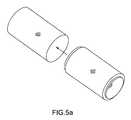
- FIG. 5Arepresents a perspective view of the jellyroll of FIG. 3 and the housing of FIG. 4 prior to the jellyroll being inserted into the housing, in accordance with some aspects of the present invention
- FIG. 5Brepresents a perspective view of the jellyroll of FIG. 3 being partially inserted into the housing of FIG. 4 , in accordance with some aspects of the present invention
- FIG. 6represents a close-up view of a crunched extending segment of the jellyroll of FIG. 3 , in accordance with some aspects of the present invention
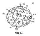
- FIGS. 7A and 7Brepresent perspective top and bottom views, respectively, of a collector plate used in an electrochemical double layer capacitor, in accordance with some aspects of the present invention
- FIG. 8represents a side cross-section of a collector insulator gasket for preventing contact between the collector plate, in accordance with some aspects of the present invention
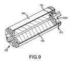
- FIG. 9represents a cutaway view of a housing, in accordance with some aspects of the present invention.
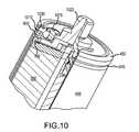
- FIG. 10represents a close up of the beaded housing of FIG. 9 with an O-ring, a lid member, and a lid insulator gasket placed and seated on top of the collector plate;
- FIG. 11represents a top perspective view of the lid member that appears in FIG. 10 , in accordance with some aspects of the present invention.
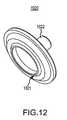
- FIG. 12represents a bottom perspective view of the lid member that appears in FIG. 10 , in accordance with some aspects of the present invention.
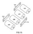
- FIG. 13represents a four capacitor cell combination that includes capacitor cells interconnected in series by bus bars, in accordance with some aspects of the present invention
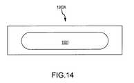
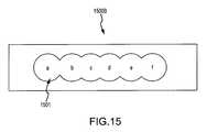
- FIGS. 14 and 15represent two variable-spacing bus bars for interconnecting energy storage cells, in accordance with some aspects of the present invention.
- FIG. 16represents a top view of a module of interconnected cells, in accordance with some aspects of the present invention.
- FIG. 17represents a perspective view of the enclosure of the module of FIG. 16 , in accordance with some aspects of the present invention.
- FIG. 18represents a top view of a tongue section, in accordance with some aspects of the present invention.
- FIG. 19represents a top view of a groove section, in accordance with some aspects of the present invention.
- FIG. 20represents a perspective view of a 1 ⁇ 1 ⁇ 6 (one row of six side-by-side cells) module, in accordance with some aspects of the present invention
- FIG. 21represents top view of the upper cover of the enclosure of the module of FIG. 20 , in accordance with some aspects of the present invention.
- FIG. 22represents a top view of a module with cell interconnected by bus bars, in accordance with some aspects of the present invention.
- FIG. 23represents a top view of a module with a stabilizer mounted over bus bars, in accordance with some aspects of the present invention.
- FIG. 24represents a stabilizer, in accordance with some aspects of the present invention.
- FIG. 25represents a top view of a module with cell interconnected by bus bars with thermal pad mounted thereon, in accordance with some aspects of the present invention
- FIG. 26represents a thermally coupled interconnect, in accordance with some aspects of the invention.
- FIG. 27represents a thermally coupled interconnect coupled to two cell terminals, in accordance with some aspects of the invention.
- FIG. 28represents three different terminal configurations, in accordance with some aspects of the present invention.
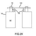
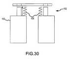
- FIGS. 29 and 30represent a thermally coupled interconnect coupled to two cell terminals and a separation mechanism, in accordance with some aspects of the invention
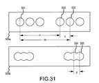
- FIG. 31represents two different thermally coupled interconnects, in accordance with some aspects of the invention.
- FIG. 32represents a top view of axially aligned cells within on half of a longitudinal enclosure in accordance with some aspects of the present invention
- FIG. 33represents a side view of a longitudinal enclosure, in accordance with some aspects of the present invention.
- FIG. 34represents a perspective view of the longitudinal enclosure of FIG. 31 , in accordance with some aspects of the present invention.
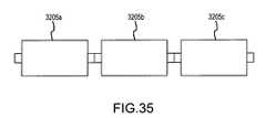
- FIG. 35represents an axial string of 3 series connected capacitors
- FIG. 36represents two capacitor interconnected by an interconnect.
- the words “embodiment” and “variant”refer to particular apparatus, process, or article of manufacture, and not necessarily to the same apparatus, process, or article of manufacture.
- “an embodiment,” “one embodiment,” “some embodiments” or a similar expression used in one place or contextcan refer to a particular apparatus, process, article of manufacture, or a plurality thereof; the same or a similar expression in a different place can refer to a different apparatus, process, article of manufacture, or a plurality thereof.
- the expression “alternative embodiment” and similar phrasesare used to indicate one of a number of different possible embodiments. The number of potential embodiments is not necessarily limited to two or any other quantity. Characterization of an embodiment as “exemplary” means that the embodiment is used as an example. Such characterization does not necessarily mean that the embodiment is a currently preferred embodiment; the embodiment may but need not be a currently preferred embodiment.
- modulemeans a plurality of interconnected electrical energy storage cells within a common enclosure.
- a “module”may further include one or more voltage monitoring circuits, voltage balancing circuits, temperature monitoring circuits, other electronic circuits, and still other components.
- FIG. 1represents a cross-section of an electrode sheet 100 for use in an electrochemical double layer capacitor.
- the electrode sheet 100includes a first electrode 110 , a second electrode 130 , a first porous separator layer 120 separating the first electrode 110 from the second electrode 130 , and a second porous separator layer 140 adjacent to the side of the second electrode 130 that is opposite the side facing the first porous separator layer 120 .
- the first electrode 110includes a current collector 112 disposed between active electrode material films 111 and 113 .
- Structure of the second electrode 130is similar to that of the first electrode 110 : a current collector 132 is disposed between active electrode material films 131 and 133 .
- the current collectors 112 and 132are made of metal foil, for example, aluminum foil. Note that each of the current collectors 112 and 132 is offset from the center of the electrode sheet 100 , extending beyond the active electrode material films 111 / 113 / 131 / 133 and porous separators 120 / 140 on a different end of the electrode sheet 100 . As represented in FIG. 1 , the current collector 112 includes a segment 112 a that extends on the right side of the electrode sheet 100 ; the current collector 132 includes a segment 132 a that extends on the left side of the electrode sheet 100 .
- the electrode sheet 100is rolled about a central axis, for example, an axis A-A′ of FIG. 1 , to form a “jellyroll” 100 ′ in which the extending segments 112 a and 132 a are exposed on respective ends of the jellyroll.
- FIG. 2illustrates a cross-section of a jellyroll 100 ′ taken along a plane that is transverse to the axis A-A′.
- the extending segments 112 a and 132 a of the respective current collectors 112 and 132provide points at which electrical contact with the current collectors may be made in the double layer capacitor built from the jellyroll 100 ′.
- FIG. 3represents a side view of the jellyroll 100 ′ prior to its placement within a housing.
- FIG. 4represents a perspective view of an aluminum housing (can) 400 capable of receiving the jellyroll 100 ′.
- the housing 400includes a generally cylindrical body 410 with an open end 420 and a bottom portion 430 .
- the housing 400is made from substantially pure aluminum, for example, 99 or 99.5 percent pure aluminum, and has a wall thickness of about 0.040 inch.
- the length and diameter of the terminal stub 432may vary in different embodiments.
- the terminal stub 432may be smooth, as in FIG. 4 , or may be threaded. Other geometries of the terminal stub 432 also fall within the subject matter of the invention.
- the length of the stubmay also vary according to intended use. Furthermore, some embodiments do not include an extending terminal stub; in such embodiments, the bottom end 430 and/or the cylindrical body 410 provide contact surfaces that serve the function of a terminal. As needed for electrical insulation, the housing 400 may have disposed about its outer surface a thin sleeve for providing electrical insulation against contact with other components in a subsequently assembled module.
- fewer or more than four indentationsare provided on the bottom portion of the housing.
- the thickness of the bottom portion 440is reduced in the indentations 434 to provide an area for laser welding the bottom portion 430 to one of the extending segments 112 a or 132 a of the jellyroll 100 ′.
- wall thickness in the indentations 434is reduced to approximately 0.025 inch.
- the interior surfaces of the housing 400are substantially smooth.
- the interior surface of the bottom portion 430includes, for example, one or more radial wedge-like ridges providing gripping and deformation forces that improve contact between the bottom portion and the extending segments of a jellyroll that is inserted into the housing. In some embodiments that include such ridges, opposing overlap between the indentations 434 on the exterior surface of the bottom portion 430 and the ridges on the interior surface of the bottom portion 430 is minimized or eliminated altogether.
- FIG. 5 arepresents a perspective view of the jellyroll 100 ′ and the housing 400 prior to the jellyroll 100 ′ being inserted into the housing 400 through the open end 420 .
- FIG. 5 brepresents a perspective view of the jellyroll 100 ′ partially inserted into housing 400 .
- a forceis applied to press the jellyroll 100 ′ against the interior surface of the bottom portion 430 .
- the applied pressurecauses the aluminum foil of the extended segment that is in contact with the interior surface of the bottom portion 430 (e.g., the segment 112 a ) to “crunch,” i.e., to squash in the axial direction, folding and compressing the protruding foil of the segment towards the center of the jellyroll 100 ′.
- FIG. 6represents a view of a jellyroll 100 ′ after segment 112 a is pressed against the interior surface of the bottom portion 430 .
- respective protruding foilsare preferably bent and crushed toward the center of the jellyroll 100 ′.
- Segment 132 ais shown to be unbent and uncrushed. Bending and crushing segment 132 a may be performed before or during subsequent attachment of a collector plate or cover. Bending and crushing of the protruding foils at both or either end of the jellyroll 100 ′ may be also performed in a step, wherein segments 112 a and 132 a are preprocessed in manner that prior to insertion into the housing they are both bent and/or crushed. It is identified that crushing of the protruding foils at segment 112 a toward the center of the jellyroll 100 ′ increases the contact area between the foil (current collector of the jellyroll 100 ′) and the bottom portion 430 .
- a laser beamis applied to the indentations 434 on the exterior surface of the bottom portion 430 .
- the laser beamheats the housing 400 and the aluminum foil of the segment 112 a in proximity to the points of the beam's application, welding the foil to the interior surface of the bottom portion 430 .
- the laser weldthus formed improves the electrical contact between the housing 400 and the current collector 112 .
- a laser welded contactIn comparison to a purely mechanical contact created by simply pressing the jellyroll 100 ′ against the bottom portion 430 , a laser welded contact generally (1) has lower resistance, and (2) is more robust and better capable of withstanding high currents, shock, vibration, and other stresses.
- a particular weld pattern formed by the laser during the welding operationcan lower the contact resistance between the current collector of the jellyroll 100 ′ and the housing 400 .
- contact resistancemay be reduced.
- an increased length laser weld patterncan be provided when other than a straight line distance between the start and the ultimate end point of a laser weld is traversed by a laser beam.
- a laser weldforms a zig-zag pattern within indentations 434 .
- laser weldingforms long oval shapes.
- Still other embodimentshave welds of other shapes, for example, laser welds with non-linear geometries. It is understood that within the context of a laser weld pattern that is substantially non linear between a start and end point traversed by a laser beam, application of the laser may be in the form of pulses and, therefore, the laser weld pattern may be comprised of a discrete number of weld points that may be used to describe the non-linear pattern, zig-zag, oval, or otherwise.
- the length of each weldis at least two and a half times the length of a corresponding indentation within which it is made. In more specific embodiments, the length of the weld is at least three times the length of the corresponding indentation. In still more specific embodiments, the weld length is between about three and a half and five times the length of the corresponding indentation.
- laser welding of the indentations 434is performed in a criss-cross sequence, moving from a first indentation to a diagonally opposing indentation.
- the criss-cross sequencetends to reduce the maximum temperature reached by certain points of the bottom portion 430 during the laser welding step, because end points of a laser weld within an indentation are not adjacent to start points in another indentation.
- the lasermay be applied to the indentations 434 in the following sequence: 434 a , 434 c , 434 d , 434 b ; other sequences are also possible.
- Welding in the criss-cross sequencemay be extended to the case of more than four indentations. For example, when five indentations are present on the bottom portion, they may be processed in the following sequence: first, third, fifth, second, and fourth. This is similar to the recommended sequences for tightening lug nuts on an automobile wheel.
- start to finish welding timemay be reduced. This effect is achieved because adjacent areas are not welded at substantially the same time, thereby eliminating the need to cool an area adjacent to an intended area to be welded.
- laser weldingmay be performed by providing two laser beams at the same time.
- the two laser beamscould be applied to corresponding opposed indentations, for example at 434 a and 434 c , and afterwards to indentations at 434 b and 434 d.
- a collector plate(or collector disk) is inserted into the housing 400 and onto the jellyroll.
- the collector platemay be inserted into the housing 400 following the laser welding of the jellyroll 100 ′ to the bottom portion 430 .
- the collector platemay be inserted into the housing 400 before welding of the jellyroll 100 ′ at the indentations 434 .
- the collector platemay be pushed against the jellyroll 100 ′ to press the jellyroll 100 ′ against the bottom portion 430 during the crunching and welding steps. Applying pressure on the collector plate crunches not only the extended segment 112 a of the jellyroll 100 ′ that is in contact with the bottom portion 430 , but also the extended segment 132 a that is in contact with the collector plate.
- FIGS. 7A and 7Brepresent perspective top and bottom views, respectively, of a collector plate 700 of a representative embodiment of a double layer capacitor.
- the collector plate 700is made from the same material as the housing 400 .
- the collector plate 700may have same temperature expansion coefficient as the housing 400 .
- the collector plate 700includes a circular lower portion 710 and a circular upper portion 750 .
- the outside diameter of the lower portion 710is slightly smaller than the inside diameter of the housing 400 in order to allow a collector insulator gasket 800 , which is shown in FIG. 8 to be placed onto the lower portion 710 .
- the housing 400 and the collector plate 700are at opposite polarity.
- FIG. 8represents a side cross-sectional view of a collector insulator gasket 800 for preventing electrical contact between the collector plate 700 and the housing 400 .
- Insulator gasket 800has a generally disc shaped geometry with an inner void and a peripheral geometry that in a cross-section can be described as comprising an “L” shape.
- the collector insulator gasketmay be made, for example, from polypropylene or Tefzel®. Other electrical insulators may also be used for this purpose.
- Collector plate 700comprise four indentations 730 a , 730 b , 730 c , and 730 d on the top surface of spoke members 720 formed on the lower portion 710 .
- the spoke members 720extend radially from the center hole 760 .
- a plurality of slots 770are formed between the spoke members 720 .
- a different number of these elementsmay be found in various alternative embodiments.
- the thickness of the lower portion 710is reduced in the indentations 730 to provide an area for laser welding the collector plate 700 to the extending segment 132 a of the jellyroll 100 ′.
- the thickness at the indentations 730is reduced to approximately 0.025 inch. Because of the reduced thickness, less laser power is needed to make a low resistance laser weld between the collector plate 700 and the extending segment 132 a of the jellyroll 100 ′ in contact with it.
- the laser welding pattern used on the current collector 700may be the same or similar to the pattern used on the bottom portion 430 .
- a zig-zag patternmay be used to increase the length of the laser welds and thereby reduce the contact resistance between the current collector of the jellyroll 100 ′ and the collector plate 700 .
- the length of each laser weldis at least two and a half times the length of the corresponding indentation 730 as measured along the center-line of the indentation 730 .
- the length of the weldis at least three times the length of the corresponding indentation 730 .
- the weld lengthis between about three and a half and five times the length of the corresponding indentation 730 .
- a criss-cross welding sequencemay be used to laser weld the collector plate 700 to the extended segment 132 a of the jellyroll 100 ′. As in the case of laser welding the bottom portion 430 , a criss-cross welding sequence used on the collector plate 700 tends to reduce the maximum temperature of certain areas.
- Diameter of the upper portion 750 of the collector plate 700is smaller than the diameter of the lower portion 710 .
- the diameter of the upper portion 750is approximately one half of the diameter of the lower portion 710 , although other diameter ratios may also be used.
- pressureis applied to the collector plate 700 so as to squeeze the jellyroll 100 ′ and crunch the extended segments 112 a and 132 a , and then the housing 400 is compressed radially in the inward direction to form a circular bead above the lower portion 710 of the collector plate 700 and the collector insulator gasket 800 .
- FIG. 9represents a cutaway view of a housing 400 containing a jelly-roll 100 ′, a collector plate 700 , and a lid member 1020 .
- housing 400comprises a bead 910 formed above collector plate 700 .
- the interior diameter of the housing 400is decreased at the bead 910 in order to hold the collector plate 700 in the position such that pressure continues to be applied to the jellyroll 100 ′.
- laser weldingis performed on the bottom portion 430 and on the collector plate 700 , as has been described above. Either the bottom portion 430 or the collector plate 700 may be welded first.
- FIG. 10represents a close up view of the beaded housing 400 with an O-ring 1010 , a lid member 1020 , and a lid insulator gasket 1030 placed and seated on top of the collector plate 700 .
- FIGS. 11 and 12represent the lid member 1020 .
- the lid member 1020includes a circular extending bottom portion 1021 , integral top terminal stub 1022 , and fill hole 1023 .
- the inner diameter of the circular extending portion 1021is slightly smaller than the outer diameter of the upper portion 750 of the collector plate 700 .
- the lid member 1020is heated, for example, heated in an oven or using an induction heating technique. When heated, the lid member 1020 expands and the inner diameter of the circular extending portion 1021 increases. The lid member 1020 can then be slipped and seated onto the upper portion 750 of the collector plate 700 , as illustrated in FIG. 10 . After the lid member 1020 cools down, it becomes securely attached to the collector plate 700 .
- the lid member 1020may be made from the same material as the collector plate 700 (e.g., aluminum) so that the two components expand and contract at the same rate, remaining securely attached to each other throughout a wide temperature range.
- the collector plate 700e.g., aluminum
- the function of the lid insulator gasket 1030is similar to that of the collector insulator gasket 800 ; it prevents electrical contact between the lid member 1020 and the housing 400 .
- the housing 400 and the lid member 1020are connected to the opposite terminals of the double layer capacitor made with these components.
- the lid insulator gasket 1030may also help to form a seal between the housing 400 and the lid member 1020 .
- the lid insulator gasket 1030may be made, for example, from polypropylene, Tefzel®, or another electrically insulating material.
- the lid insulator gasket 1030 and the collector insulator gasket 800are made from the same material, have the same dimensions, and therefore are interchangeable.
- FIG. 10shows show a cutaway view of the housing 400 after a crimp seal is formed by lip 450 .
- the crimp sealsecures the lid member 1020 (as well as various other components discussed above) within the housing 400 .
- Electrolytic solutionmay then be introduced into the housing 400 through the fill hole 1023 in the lid member 1020 . After the housing 400 is filled with the electrolytic solution, the fill hole 1023 is closed with a plug 1075 .
- the electrolytic solutionis not shown separately, but it should be understood that the solution permeates the jellyroll 100 ′ and the space around it within the housing 400 . In this manner an electrochemical double layer capacitor may be obtained.
- Electrical energy storage cellssuch as the capacitor 1300 may be combined into multi-cell modules.
- the cellsmay be coupled in parallel, in series, or both in parallel and in series. Interconnections between individual cells of a module may be effected by bus bars that attach to the cells' terminals.
- FIG. 13represents an exploded view of four capacitor combination 1400 that includes capacitor cells 1405 a - 1405 d interconnected in series by bus bars 1410 a - c . Only four interconnected capacitor cells are shown, but it is understood that fewer or more cells could be interconnected, in series and/or in parallel.
- Each bus barcomprises, at each end, a void that is placed over a respective terminal of a cell.
- the voidis dimensioned to be larger in geometry or radius than the terminal, but as will be discussed later below, the void may have other dimensions.
- the bus barmay be laser welded to a capacitor terminal that is inserted into the void. The laser weld provides a low resistance path through which large currents can pass between capacitors without generating excessive heat. Interconnection of a bus bar to a terminal using other than laser welding or without additional materials is discussed further below.
- Bus bar 1410 aconnects the cells 1405 a and 1405 b
- bus bar 1410 cconnects cells 1405 b and 1405 c
- bus bar 1410 bconnects the cells 1405 c and 1405 c .
- the bus barsmay be used to connect positive and negative terminals of the cells in a series capacitor configuration. In one embodiment, the bus bars may be used to connect terminals of cells to effectuate a parallel capacitor configuration.
- bus bars 1410 shown in FIG. 13allow only one inter-cell spacing. In other embodiments, bus bars that provide variable cell-to-cell spacing may be used.
- FIGS. 14 and 15represent two bus bars 1500 A and 1500 B that may be used in alternative embodiments.
- bus bar 1500 Aincludes an elongated slot 1501 with generally straight edges along its length for receiving terminals of cells any where within the slot.
- bus bar 1500 Bhas a plurality of discrete positions 1502 a - 1502 f for receiving cell terminals.
- Bus bars 1500 A and 1500 Bcan be used to effectuate the efficient and quick assembly of cells in parallel and/or series strings. Because bus bars 1500 A and 1500 B allow coupling at multiple locations along their length, cells can be rapidly interconnected with more than one cell to cell spacing.
- Such an ability to couple cells with one bus barcan be used to eliminate or reduce the need to stock multiple bus bars, wherein each would be used to achieve a different cell to cell spacing. Rapid assembly of different cell modules with different cell to cell spacing is effectuated as well. Subsequent welding may be used to make the connection permanent, or other techniques described further below may be used. Because only one standardized bus bar can in this manner be used, change over from one bus bar with a particular spacing, to another bus bar with another spacing is preferably eliminated when other cell to cell or terminal to terminal spacings are desired. Other embodiments of bus bars and other methods of interconnection of cells are within the scope of the invention, and will be described further below.
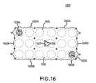
- FIG. 16represents a top view of a module 1600 .
- Module 1600comprises an upper cover 1635 , which is substantially flat.
- the openingsmay be used is some embodiments to provide access to voltage, module and cell balancing, and temperature monitoring output signals provided by internal circuits. Access to certain internal points provided by the connectors exposed in the openings 1636 may be desirable in some schemes.
- Also seen in FIG. 16are outlines of 18 series interconnected cells 1405 within the module 1600 .
- the openings 1636 and 1637may be sealed by gaskets or the like.
- FIG. 17represents a perspective view of module 1600 .
- a lower cover 1640(not shown) may be similar in shape to the upper cover 1635 , with or without openings.
- module 1600is a 1 ⁇ 3 ⁇ 6 module that can accommodate three rows of six side-by-side (rather than end-to-end) series interconnected cells 1405 disposed within.
- the cells 1405are interconnected in series string of cells by bus bars 1410 in a manner similar to that illustrated in FIG. 12 .
- each cell 1405comprises a nominal operating voltage of about 2.5 volts so that a nominal 45-volt potential difference (18 ⁇ 2.5 volts) may be made available at ends of the series string at terminals 1615 A and 1615 B.
- module 1600includes 8 components:
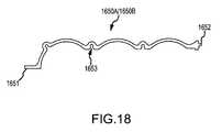
- FIG. 18represents a top view of tongue side section 1650 A and a bottom view of a tongue side section 1660 B.
- flange 1651is designed for fastening with nuts and bolts, screws, rivets, or other fasteners to a corresponding flange on one of the sides of the end panel 1645 A or 1645 B, as shown in FIGS. 16 and 17 .
- tongue section 1650 Acomprises a “tongue” 1652 , which is rounded at its end.
- the tongue 1652is designed to couple to and interlock with a corresponding “groove” on a side section 1660 A or 1650 B, as will be illustrated in more detail below.
- both ends of the end panels 1645 A and 1656 B, and side sections 1650 / 1660comprise tongue or grooves (not shown) to allow the end panels and the side sections to be slideably coupled to each other and to thus eliminate the use of fasteners in their interconnection to each other.
- FIG. 19represents a bottom view of a groove side section 1660 A and a top view of a groove side section 1650 B.
- Flange 1661is designed for fastening to the flange on one of the sides of the end panel 1645 A or 1645 B.
- Sections 1660 A/ 1650 Bcomprise a groove 1662 .
- the groove 1662is designed to accept the tongue 1652 when respective tongue and groove side sections are aligned vertically and slid towards each other until they are at the same vertical level. Thereafter, the tongue and groove side section may be interlocked with each other in a slideable interference joint.
- one or more of the module 1600 components at points of interface with other componentsmay comprise a gasket or other sealant material that may seal the interior of the module from that of the exterior.
- the side sections 1650 / 1660are contoured generally along the outlines of outermost cells 1405 of the module 1600 to provide a close fit between the walls of the module 1600 and the cylindrical shape of the cells.
- the present use of contoured panelsprovides a number of benefits, including improved heat transfer from the cells to the housing, and enhanced structural rigidity. Enhanced heat transfer occurs because of the reduced free space within an enclosure that is effected by the contoured side panels, as well from the reduced heat transfer distance from cell to panel.
- modulescomprising flat outer surfaces, which when closely positioned next to each other would have close or reduced space between the flat surfaces, when modules made with contoured outer surfaces are placed next to each other, more open space between the contoured surfaces may be provided between the modules. Ventilation and cooling of the modules can thus be improved.
- upper and lower covers 1635 and 1640may be used to provide structural rigidity to the module 1600 .
- end panels 1645 A/B and the side sections 1650 / 1660can also be joined using a tongue and groove joint at respective points of joinment.
- fasteners 1631 shown in FIG. 17e.g., nuts and bolts, screws, rivets
- a module 1600can be expanded in size by inserting intermediate side sections between adjacent tongue and groove side sections 1650 and 1660 .
- An intermediate side sectioncan be designed to have a tongue on one end for coupling to its corresponding groove side section, and a groove on the other end for coupling to its corresponding tongue side section.
- An intermediate side sectionmay be designed to lengthen the rows of the module 1600 by one, two, three, or even a larger number of capacitor cells.
- multiple intermediate side sectionsmay be used on each side of the module 1600 .
- two identical or different intermediate side sectionsmay be inserted between each set of the side sections 1650 / 1660 . If each of the two intermediate side sections is designed to lengthen the rows of the module 1600 by two cells, the module 1600 would be capable of accepting three rows of ten cells each.
- the upper cover 1635 and the lower cover 1640would be replaced with appropriately-lengthened upper and lower covers designed for the lengthened module.
- the module 1600may thus be expanded in a manner similar to the expansion of a dining room table with one or more extra panels.
- a module's widthmay also be adjusted by insertion or removal of additional end panels. Indeed, a module may be built without any number of end panels.
- FIG. 20is a perspective view of a 1 ⁇ 1 ⁇ 6 (one row of six side-by-side cells) module 2300 .
- Cells internal to the module 2300are similar to the cells of the module 1600 described above.
- the cellsare interconnected in series such that in one embodiment a nominal 15-volt potential difference may appear between terminals 2315 A and 2315 B. Different electrical interconnections may be made in alternative embodiments of the module 2300 .
- FIG. 21represents a top view of module 2300 .
- the enclosure of the module 2300includes the following components.
- the upper cover 2335is substantially flat and, except for its geometry, is otherwise similar to the upper cover 1635 of FIG. 16 .
- openings 2338 A and 2338 Bmay be designed to receive the terminals 2315 A and 2315 B, and opening 2337 provides access to connectors that may be used for external monitoring of internal signals. Appropriate seals or covers may be provided at the openings as needed or desired.
- a lower cover 2340is similar in shape to the upper cover 2335 , but without terminal openings or openings for signal monitoring or voltage balancing. The lower cover 2340 is not illustrated.
- the enclosure of the module 2300includes a pair of the tongue side sections 1650 A and 1660 B, and a pair of the groove side sections 1660 A and 1650 B. These components have already been described and illustrated in detail in relation to the module 1600 . Referring back to FIGS. 18 , 19 , note slots 1653 and 1663 formed on the inner surfaces of the tongue and groove side sections 1650 and 1660 , respectively. Printed circuit boards with balancing, monitoring, or other circuits may be inserted into or between these slots.
- the module 2300may also be expanded in length by inserting intermediate side sections between the tongue and groove side sections 1650 and 1660 , as has been described above in relation to the module 1600 . Multiple side sections may be used on each side of the module 2300 .
- the enclosure of the module 2300does not include end panels, and is therefore narrow enough to accommodate a single row of capacitor cells, such as the cells 1405 .
- a modulemay include end panels similar but narrower or wider than the end panels 1645 A and 1645 B.
- an enclosure with slightly narrower end panelsmay be used for 1 ⁇ 2 ⁇ N modules, i.e., modules of 2 rows of N cells arranged side-by-side.
- the number Nmay vary, e.g., the length of the rows may depend on the number and size of the intermediate side sections inserted between the tongue and groove side sections 1650 and 1660 .
- an enclosure with end panels that are wider than the end panels 1645 A and 1645 Bmay be used for 1 ⁇ M ⁇ N modules, where M may be larger than three, i.e., the module may have more than three rows of side-by-side cells.
- end panelsmay be used on each end of an enclosure.
- two or more end panelsare interconnected at each end of the module, to allow customization of module width. This is similar to the use of intermediate side sections to customize module length, as has been described above in relation to the modules 1600 and 2300 .
- the end panelsmay include tongue and groove portions at their sides, allowing the end panels to interconnect in the same manner as the tongue and groove side sections 1650 and 1660 interconnect using their respective tongues 1652 and grooves 1662 .
- a module widthmay also be expanded in a manner similar to the expansion of a dining room table with one or more extra panels.
- multiple end panels on the same endare interconnected using other fasteners, for example, nuts and bolts, screws, or rivets.
- a moduleis customizable in only one of the three dimensions, be it length, width, or height.
- a moduleis customizable in two of the three dimensions, for example, length and width, length and height, or width and height.
- a moduleis customizable in all three dimensions. In this manner, modules with different cell numbers and configurations may be assembled from a relatively small number of standardized components. Moreover, the tongue and groove joints decrease the need for use of fasteners in such customizable modules.
- the preferred embodimentcomprises covers, end panels, and side sections that are made of aluminum, for example, extruded or molded aluminum, however, in different embodiments one or more of these components could be made of other material.
- the top and bottom coversare preferably made of a thermally conductive material such metal to conduct heat away from the capacitors, while other components may be made of alternative materials, for example, light weight material such as plastic.
- FIG. 22there is seen a plurality of series interconnected cells 1405 within a module 1600 .
- the module 1600is shown with its top cover removed. Adjacent cells in the series string are interconnected at their terminals by bus bars 1410 . Top bus bars are seen in their entirety and bottom bus bars are seen hidden by respective cells they are connected to.
- the present inventionidentifies that when cells are interconnected within a module, their movements relative to the walls of the module may be desired to be restricted or substantially eliminated.
- a flat relatively rigid stabilizing element with one or more cutoutsassists in performing this function.
- Terminals 1638 A and 1638 Bprovide access to ends of the series string of cells housed within the module 1600 .
- a stabilizer 2670is shown placed on top of the capacitor cells.
- a surface of the stabilizeris defined by the angled hatched lines.
- the stabilizer 2670may be made from any number of rigid or semi rigid materials.
- a similar stabilizermay be present at the bottom of the capacitor cells 1405 . In one embodiment, stabilizer 2670 is about 0.062 inches thick.
- the stabilizer 2670need not be absolutely rigid, however, the stabilizer 2670 should be sufficiently rigid so as not to flex to a point where the capacitor cells 1405 move excessively (beyond design limits) under forces and in positions that the module 1600 may be expected to experience.
- Stabilizer 2670preferably comprises a plurality of cutouts 2671 .
- cutouts 2671are dimensioned to closely fit over the outer dimensions of bus bars 1410 and terminals 1638 .
- stabilizermay closely fit over cells 1405 .
- Cutouts 2671are positioned relative to each other in a similar relationship to that of the bus bars 1410 and terminals 1638 . In other words, when placed over the top of the cells 1405 and terminals 1638 , the cutouts 2671 will preferably slip fit over the bus bars and terminals. When positioned in this manner, the cutouts 2671 preferably restrict movements of the cells 1405 relative to each other in a plane of the stabilizer 2670 .
- stabilizer 2670also has an outer periphery that is similar in geometry to the inner periphery of the module 1600 .
- the outer periphery of stabilizer 2670When placed over the top of the cells 1405 and terminals 1638 , the outer periphery of stabilizer 2670 preferably abutably slips within the module 1600 walls. When positioned in this manner, the stabilizer preferably restricts movements of the cells 1405 relative to the module 1600 walls.
- desired functionalitymay be achieved with other geometries of stabilizer 2670 , for example, as with a rectangular shape indicated by the dashed lines, or some other geometry that effectuates restraint of movements of cells 1405 relative to the module 1600 walls.
- stabilizer 2670may also be used to restrict movement of the cells 1405 in the vertical dimension (transverse to the plane of the stabilizer 2670 ) when it is dimensioned with a thickness that is slightly more than a free distance between the top surface of each of the cells 1405 and a bottom surface of a subsequently attached cover.
- the stabilizer 2670when the stabilizer 2670 is positioned over the bus bars 1410 , the stabilizer may become pressed against the top surface of the cells, and when a cover is attached to the module 1600 , the cover will press against the stabilizer and, hence, the cells. In this manner the cells 1405 may become further restrained within the module 1600 .
- a stabilizer 2670 with a sufficient thicknessmay be used to provide sufficient clearance between the bus bars 1410 and a subsequently attached cover. For example, when a stabilizer 2670 is placed over the bus bars 1410 and over a top surface of the cells 1405 , if it is of sufficient thickness, an upper surface of the stabilizer may extend above an upper surface of the bus bars and, thus, prevent any contact between a subsequently attached cover and the bus bars.
- one or more insulator and/or thermal padsmay be placed between a subsequently attached cover and the bus bars 2610 .
- thermal padsmay also be placed between the peripheral cells 1405 that are directly opposite wall of the module and the wall so as to provide a thermal transfer path between the cells and the walls of the module, and as well, to provide an additional restraint of movement between the cells and the module.
- thermally conductive pads and/or electrical insulatorsare represented by angled lines.
- Thermal padsmay be made from a sheet of electrically-insulating material having high thermal conductance with an adhesive applied to one or both sides of the sheet.
- Individual thermal pad piecesmay be applied to the top of each bus bar 1410 .
- Each piecemay be shaped as, and adhere to, its corresponding bus bar 1410 . In this way, the amount of the thermal pad material may be minimized, reducing total module cost. It is identified that when thermal pads and/or insulators are applied to bus bars 1410 , and when a cover is attached to the module 1600 , the cover will preferably press against the thermal pads. In this manner, the thermal pads may also act to restrain movement of the bus bars, and hence cells 1405 , relative to the walls of the module, as well as electrically insulate the bus bars 1410 from the module 1600 .
- an uncured thermally conductive sheet made of conductive silicon or other polymermay be used to provide heat transfer, sealing, as well as stabilization of components within a module, for example as available from Saint Gobin Performance Plastics Corporation, Worcester, Mass. 01605 as model TC100U.
- a sheet of thermally conductive materialmay be shaped with a slightly bigger outer dimension than stabilizer 2670 , such that when placed over the stabilizer (when used) and/or the bus bars, it conforms to the outer periphery of the module 1600 : If such a thermally conductive sheet is subsequently pressed by a top and/or bottom cover onto the periphery of the module 1600 , it may be used to seal the periphery.
- thermally conductive sheetsuch as TC100U
- TC100Uthermally conductive sheet
- those skilled in the artthat such a sheet may cure and bond to a surface it is placed on.
- a thermally conductive sheetmay become heated when bus bars 1410 conduct current.
- Such or other heatingmay be used to bond the bus bars 1410 to the top or bottom cover via the thermally conductive sheet, and thus provide a stabilizing mechanism that restrains movement of the cells. It is identified that thermally conductive sheets or pads may be used in conjunction with or without embodiments of a stabilizer 2670 .
- a stabilizer 2670may be populated with one or more components or circuits 2672 that may be used in some module embodiments.
- the stabilizer 2670may be comprised as a printed circuit board with electronic connections and circuitry on the printed circuit board provided to effectuate cell-to-cell voltage balancing, voltage monitoring, temperature monitoring, alarm signaling, and/or other functions.
- the thermal padsmay be provided on bus bars 1410 with sufficient thickness to provide electrical clearance between the circuits and the circuits 2672 .
- thermal padsmay also be placed on top of the printed circuit board components, providing electrical insulation and thermal conduction between the components and an upper cover of the module 1600 .
- the stabilizer 2670may be formed to comprise a plurality of bus bars 1410 that are disposed within the stabilizer, for example as may be formed by molding a stabilizer about bus bars that are positioned in a predetermined pattern that corresponds to their intended interconnection to terminals of cells 1405 that are disposed with a particular cell to cell spacing. In this manner the cells 1405 may be positioned with the desired terminal to terminal spacing, and subsequently the bus bars 1410 within a stabilizer 2670 may be placed over the terminals in one step. The bus bars can be subsequently coupled more permanently to the respective terminals.
- bus bars as described abovewill for the moment be described more generically as interconnect(s) 1000 and in a context that may find applicability in many fields.
- FIG. 26represents a preferred embodiment of a bus bar or interconnect 1000 .
- interconnect 1000may comprise a conductor.
- interconnect 1000may comprise a metal.
- interconnect 1000may comprise aluminum.
- interconnect 1000is formed to include one or more through hole or void 101 that is formed therein.
- devices 102comprise a housing 103 , and at least one terminal 104 .
- terminal 104may comprise a conductor.
- terminal 104may comprise a metal.
- terminal 104may comprise aluminum.
- ends of the terminals 104extend through voids 101 of an interconnect, but in other embodiments, the ends of the terminals may be disposed within the voids such that they do not completely extend through the voids.
- voids 101may extend only to a certain depth within an interconnect.
- devices 102comprise a general class of devices that may be joined mechanically and/or electrically.
- devices 102comprise batteries.
- devices 102comprise capacitors. In one embodiment, devices 102 comprise double layer capacitors. In one embodiment, housing 103 comprises a geometry and dimension such that a terminal 104 can be implemented thereon. As described further below, in one embodiment, two or more devices 102 having a terminal 104 may be coupled by one or more interconnect 1000 without the use of welding or other intermediate components or elements, for example, solder, brazing, adhesives, nuts, bolts, clamps, or the like.
- terminals 104comprise a top portion 104 b and a bottom portion 104 a that are separated in distance by a height “h”.
- a periphery of the top and bottom portionmay be described by a geometry, for example, a circle, a rectangle, an ellipse, a square, a polygon, or the like; for example, a radius defining an outer surface of the terminal may or may not vary at different cross-sections between the top and bottom of terminal 104 .
- a geometry of the terminalmay change, for example, as in a terminal shaped in the form of a truncated cone.
- a radial dimension of a void 101 comprising a circular geometryis smaller than or the same as a radial dimension of a cylindrical terminal 104 , a fit of the terminal within the void may be difficult if not impossible to achieve, in which case a solder, a weld, or a physical force may be required to effectuate coupling of the interconnect 1000 to the terminal.
- a solder, a weld, or a physical forcemay be required to effectuate coupling of the interconnect 1000 to the terminal.
- its applicationcould act to damage a terminal 104 , the interconnect 1000 , or a device 102 itself.
- an interconnect 1000may be utilized with voids 101 that comprise a radial geometry that is the same as or smaller than a radial geometry of a terminal 104 , and that high integrity and low resistance coupling therebetween can be made without additional components or material and without damage to the terminal, interconnect, or device.
- a terminal 104comprising a radial geometry that is the same as or larger than a radial geometry of a void 101 can be coupled to an interconnect 1000 without use of an additional component or material and without damage to the terminal, interconnect, or device.
- terminals 104comprise an outer cylindrical surface that can be defined by a height, and a cross-sectional radial dimension that is substantially constant.
- interconnect 1000comprises at least one void 101 formed within the interconnect that can be defined by a height and a cross-sectional radial dimension that is substantially constant.
- the substantially constant dimension of the at least one void 101is the same as or less than that of the terminals 104 .
- the void 101extends through the interconnect; although in other embodiments, a void can be formed through only a certain thickness of an interconnect.
- terminals 104comprise a cylindrical geometry with a height of about 0.15 inches and a circular radius of about 0.553 inches.
- interconnect 1000comprises at least one void 101 with a circular radius of about 0.550 inches and a height of 0.14 inches. The respective measurements given, were taken at room temperature of about 70 degree Fahrenheit.
- the present inventorshave identified when an interconnect 1000 is heated to a temperature of about 350 degrees Fahrenheit, a radial dimension describing a void 101 may be increased such that the void may be slipped over a terminal 104 with a larger radial dimension with use of minimal force. It is identified that after a subsequent equilibration of the temperature of the interconnect to that of the terminal by cooling, forced or natural, the radial dimension describing the void 104 becomes reduced to thereafter form a strong rigid mechanical and/or electrical connection between the terminal 104 and interconnect 1000 .
- a terminal 104 and an interconnect 1000comprise an aluminum material
- the interconnectacts to clamp about the terminal at points of interface between the terminal and interconnect.
- the clamping forcesact to constrain the terminal 104 within the void 101 of the interconnect 1000 .
- the forcesare of sufficient strength to break through oxide layers that may have been present on the surface of the terminals.
- a terminal 104is a terminal of a double-layer capacitor
- the subsequent connection formed between a terminal 104 and an interconnect 1000is of sufficient strength that the interconnect cannot be separated from the terminal without damage to the capacitor.
- the resultant assembly formed of the capacitors and the interconnectscan be relied on to be rigid and/or self-supporting.
- the assemblycan be relied on to be rigid and/or self-supporting over a range of ⁇ 50 degrees Celsius to +85 degrees Celsius.
- both the terminals 104 and the interconnect 1000will expand and contract at the same or similar rate when exposed to a particular temperature, in which case the radial dimensions of the terminals 104 and the voids 101 would be expected to change at the same or similar rate, and in which case the clamping forces generated by the interconnect would be expected to stay more or less constant.
- the radial dimensions of the terminals and the voidscan in this manner be expected to maintain integrity of a connection between one or more devices over a wide range of operating temperatures without the use any additional component or material, and that the connection therebetween can be considered to be as mechanically and/or electrically permanent as that provided by the prior art.
- high integrity and low resistance couplingmay be maintained even when over 2000 amperes of current flows between a terminal and an interconnect, as may occur when double-layer capacitors are used. Such coupling may be maintained despite the high temperatures that may be generated at the terminals and without the need for additional materials or devices to maintain the coupling.
- low resistance and high integrity couplingis maintained over a temperature range that spans ⁇ 40 to +85 degrees Celsius.
- a terminal 104may be cooled to a temperature sufficient to reduce the radius of the terminals, and a void 101 of an interconnect 1000 can subsequently be easily slipped onto the terminal. After equilibration of temperatures between the terminal 104 and the interconnect 1000 , expansion forces of the terminal against the interconnect can be used to achieve similar effects and advantages as described above.
- a terminal 104comprises a geometry different from that of a circular cylinder, for example, a rectangular or elliptical cylinder
- such geometrymay be used with correspondingly shaped void 101 to further enhance the integrity of a connection between an interconnect 1000 and the terminal.
- the elliptical shape of the terminal within the voidcan be utilized to resist torsional movements of the terminal relative to the interconnect, for example as may occur during shaking or vibration that may be applied to a module of multiple devices coupled by one or more interconnect 1000 . It is identified that use of terminals and interconnects comprising the other than circular geometries can be implemented in the context of temperature induced expansion or contraction fitting of an interconnect 1000 onto a terminal 104 as has been described above.
- a terminal 104comprises a gradually or slightly changing cross-sectional geometry along its height, for example, as embodied by a truncated cone, and wherein voids 104 of an interconnect 1000 comprise a corresponding matching geometry
- gradually or slightly changing geometrymay facilitate alignment and the fitting of a void 101 over a terminal 104 .
- a cross-sectional bottom portion of a voidis larger than a cross-sectional-portion of a top portion of a terminal, alignment and fitting of the terminal within the void can be more easily effectuated.
- only an interconnect 1000is provided with a void with a gradually or slightly changing geometry.
- a voidis provided with a gradually or slightly changing geometry, for example, as by cylindrical void comprising a chamfered or taper at one end, for example, at a bottom end that is first fitted over a terminal.
- a stabilizer 2670FIG. 24
- provision of voids with gradually or slightly tapered geometries within interconnects 1000can be used to more easily align the interconnects to corresponding terminals 104 of the devices.
- terminals and interconnectsmay each comprise a material that has a different temperature coefficient.
- materialsis used for terminals 104 that is different from that of interconnects 1000 , it is identified that above or below a certain temperature, a radial geometry of a void 101 or terminal 104 may change at different rate than a corresponding terminal or void, in which case the integrity of a previously temperature induced expansion or contraction connection made therebetween may become degraded.
- an appropriate selection of materials with different temperature coefficientsmay be made for use as an interconnect or terminal such that degradation of a connection between a terminal and an interconnect may be made to occur in predictable manner, in which case an interconnect could be used as a “fuse.”
- an interconnectcould be used as a “fuse.”
- the compression or expansion forces between a terminal and an interconnectcould be made to weaken to a point that a mechanical or electrical connection therebetween could be caused to fail in a predictable manner.
- the electrical devicevia its thermally fitted interconnect, could be selectively disconnected from a terminal and a path of current flow.
- release of an interconnect from a terminalcan be assisted by use of gravity or an assist device, for example as represented by spring 106 , which when placed against the interconnect, at a particular temperature the spring could be used to provide a force to assist in separating interconnect 1000 from a terminal 104 . It is understood that design of spring 106 or other disconnect device would for safety need to consider the presence of surrounding enclosures and electrically charged devices.
- Interconnects 500 a and 500 beach comprising voids with a geometry that corresponds in whole or in part to the geometry of a corresponding terminal 104 .
- Interconnects 500 a and 500 bprovide functionality similar or the same to that of interconnects 1500 A and 1500 B represented by FIGS. 14 and 15 .
- the voids 501 , 502 503 , 504 , 505may be shaped to comprise at least in part a circular or semicircular geometry. Positioning of terminals of cells within the voids of only one of the interconnects 500 a or 500 b can subsequently be used to effectuate a plurality of different cell-to-cell spacings.
- manufacture of modulesmay require the ability to provide interconnected devices as modules assembled in many different form factors.
- the assembly of modules into different form factorsmay be advantageously facilitated using one or more module component as previously described herein.
- module componentAs previously described herein.
- thermal induced expansion or contraction fitting of interconnects to terminalsquick and easy interconnection of a series of devices and their integration into a module may be further facilitated.
- expansion or contraction fittinga desired terminal-to-terminal spacing of devices or cells can be achieved quickly to achieve and match a particular configuration or module form factor.
- such terminal to terminal spacingmay be dictated by the particular dimensions of the components stocked for manufacture of modules, for example, the side sections 1650 and 1660 described above.
- the present inventionfacilitates that modules in multiple form factors can easily and very quickly assembled using a minimum number of such stock components.
- Such functionalitycan be used to provide customized low cost modules to end users to fit a particular application “on the fly.”
- adjacent voidsfor example, voids 502 , 503 and 504 , 505 . . . may be separated by a distance “Z”.
- adjacent voidsfor example voids 504 , 505 may dimensionally overlap each other. It is identified that a corresponding terminal of an appropriately dimensioned cell or device could be coupled to any one of the voids, for example, 501 , 502 , 503 or 504 , 505 .
- terminals of the cells or devicescould be coupled to different ones of voids 501 , 502 , 503 or 504 , 505 , in which case, many different form factor modules could be assembled using only one in stock interconnect. It is identified that such assembly of modules by interconnects may be effectuated using temperature induced expansion or contraction fitting as described above, in which case a radial dimension of the voids 501 , 502 , 503 or 504 , 505 , could be provided to be the same or slightly smaller than that of a corresponding device terminal.
- an interconnect 500 a , 500 bmay also find utility in applications other than those that utilize temperature induced expansion or contraction fitting.
- the interconnectscould be coupled to terminals of devices by means of a solder, epoxy adhesive, weld, or other suitable fastening material.
- a stabilizer 2670may be formed to comprise a plurality of bus bars 1410 .
- bus bars 1410may comprise thermally fitted interconnects as described above.
- expansion of the voids within the bus barsallows the plurality of bus bars to be slipped onto and to be coupled to a plurality of cell terminals in one step without use of solder, epoxy, adhesive, weld, or other fastening material. In this manner, alone, or in combination with other aspects of the invention described herein, cheap, rapid and reliable assembly of interconnected capacitors may achieved.
- Electrical connections between the terminals of the cells 1405 and voltage balancing, voltage monitoring, or other electronic components or circuitsmay be made with wires and/or circuit traces on the stabilizer 2670 .
- one end of a wireis soldered to an appropriate point of an electronic circuit and the second end of the connecting wire is “staked.”
- “staking” of the wiremaybe performed as follows.
- a small staking holeis made, e.g., drilled, in a bus bar 1405 .
- the staking holemay be made before or after the bus bar is attached to terminals of a cell 1405 .
- the diameter of the staking holeshould be sufficient to receive the conductor of the connecting wire, but generally not be much larger than the conductor.
- the conductor of the connecting wireis then inserted into the staking hole and held in position while a high impact force is applied to one or more surfaces of the bus bar so as to deform the staking hole, creating a mechanical and electrical “staking” connection between the connecting wire and the bus bar, and preventing the connecting wire from slipping out of the hole.
- a connecting wiremay also be staked directly to small hole made in a terminal of a cell. In this manner, an electrically robust terminal can be effectuated mechanically without the use of solders, adhesives, etc.
- individual cylindrical cellsare arranged side-by-side in one or more rows.
- a module's cellsmay be arranged end-to-end, in one or more axially oriented string or column, resulting in configurations of L ⁇ M ⁇ N cells, where the number L indicates the number of axially aligned cells. It has been identified that certain applications can use long strings of cell more effectively than configurations where the cells are not arranged end-to-end. For example, in an automotive application space may be limited, presenting design difficulties in accommodating a 1 ⁇ 3 ⁇ 6 cell configuration.
- a long string cell configuratione.g., a 9 ⁇ 1 ⁇ 2, 6 ⁇ 1 ⁇ 2, or 12 ⁇ 1 ⁇ 1 configuration
- a long string cell configurationmay be positioned within or along a long hollow frame member, frame pillar member, a hollow roof member, or the like.
- a further protective shellcan be provided around and about cells to protect the cells, such as during an accident.
- the modulescould be slideably accessible/removable for easy servicing or replacement.
- only one end of the cell string(for example a positive end) would be connected by a long heavy-duty cable through which a path for high current that may flow through the cells may be provided.
- the other end of the cell stringcould be connected by a short heavy-duty cable, or through the module housing itself, to the frame member, which could then provide a completed path for current flow. Because a long heavy-duty return path cable need not be used in this embodiment, the weight, cost, and resistance associated with such cable can be eliminated.
- FIG. 32represents a top view of a 13 ⁇ 1 ⁇ 2 module 2900 with its top portion removed, wherein two vertical strings of thirteen cells 2405 are arranged next to each other in a series connection to provide a nominal 65 volt output.
- FIG. 33represents a side view with a longitudinal top 3020 and bottom 3025 portion coupled together to form a sealed module 2900 .
- FIG. 34represents a perspective view of module 2900 .
- a front end cover 3010can be seen at the front of the module 2900 .
- the module 3010includes a rear end cover (which is obscured from view in the Figures) at the rear of the module.
- the top 3020 and bottom 3025 portionsare joined together along side flanges 3030 .
- the longitudinal pieces 3020 and 3025may be joined together using nuts and bolts inserted through holes in the side flanges 3030 .
- the longitudinal pieces 3020 and 3025may be joined using tongue and groove connectors, or other fasteners.
- the longitudinal pieces 3020 / 3025may be cut to length as needed from a longer extruded piece with appropriate cross-section. One base extruded piece may thus be used to make the enclosure for accommodating any string length of cells.
- longitudinal pieces 3020 and 3025comprise longitudinally positioned slots which may be used to slideably receive a printed circuit board with one or more voltage monitoring circuits, voltage balancing circuits, temperature monitoring circuits, and/or other electronic circuits used in the module 2900 .
- FIG. 30represents a circuit 3026 positioned within a slot of a bottom portion.
- FIG. 35represents a single axial string 3200 of six capacitor cells 3205 a - 3205 c .
- the cells 3205may be joined together in various ways.
- the cell terminalsmay be threaded in a complimentary manner.
- one terminal of each cell 3205may be threaded as a bolt, while the opposite terminal may appropriately dimensioned and threaded as a matching nut, or vice versa.
- the cells 3205may then be screwed into each other to obtain the vertical string 3200 .
- FIG. 36there is represented two cells 3205 , each comprising two extending terminal stubs 3306 .
- two adjacent cells 3205can be joined into a vertical string by an element 3310 placed therebetween.
- the elementis shaped generally as a circular washer.
- Terminal stubs 3306 of adjacent cells 3205can preferably be placed within a void formed within the element 3310 such that the adjacent cells 3205 abut near to or against the element.
- the element 3310can subsequently be welded to the cells 3205 at one or more points about its periphery 3311 . In one embodiment, welding is performed using a laser.
- element 3310may be dimensioned with a centrally disposed void that is the same or slightly smaller in diameter than the terminal stubs 3306 .
- terminals of two cells 3205may be slideably inserted into the void. After cooling of the element, the two cells may preferably be mechanically and electrically interconnected by the element 3310 such that subsequent welding or other material is not necessary to ensure that a strong self-supporting connection is made therebetween.
- longitudinal strings of capacitorsare described to be coupled by a bus bar or interconnect shaped as a washer, for example, a disk with a centrally disposed hole or apertures formed therein, it is understood that other shapes are within the scope of the invention, for example an element 3310 in other embodiments could comprise an elliptical, a square, a rectangular, or other geometry with one or more void formed therein.
- an element 3310may comprise two opposingly disposed voids, wherein the voids are formed within an element 3310 on opposite sides, but are separated by some portion of element 3310 (not shown).
- FIG. 34represents two cells 3205 coupled by an intermediate element 3310 ; the vertical string can be extended to any length in the manner described to effectuate a low resistance and strong interconnection of a long series string of cells.
- the vertical stringcan be integrated into a module 2900 described above, or, because it can be self-supporting, by itself in a particular application allowing such use.
- FIG. 34also shows a staking hole 3313 on the side of the washer 3310 .
- the staking hole 3313may be used for attaching a connecting wire to the terminal using the staking process described above.
Landscapes
- Engineering & Computer Science (AREA)
- Power Engineering (AREA)
- Microelectronics & Electronic Packaging (AREA)
- Chemical & Material Sciences (AREA)
- Chemical Kinetics & Catalysis (AREA)
- Electrochemistry (AREA)
- General Chemical & Material Sciences (AREA)
- Inorganic Chemistry (AREA)
- Electric Double-Layer Capacitors Or The Like (AREA)
Abstract
Description
- Nanjundiah et al., U.S. Pat. No. 6,627,252, entitled Electrochemical double layer capacitor having carbon powder electrodes;
- Bendale, et al., U.S. Pat. No. 6,631,074, entitled Electrochemical double layer capacitor having carbon powder electrodes;
- U.S. patent application entitled DRY PARTICLE BASED ADHESIVE ELECTRODE AND METHODS OF MAKING SAME, Application Ser. No. 11/116,882;
- 1. The
upper cover 1635; - 2. A lower cover1640 (not shown);
- 3.
End panels - 4. “Tongue”
side sections side sections
- 1. The
Claims (7)
Priority Applications (1)
| Application Number | Priority Date | Filing Date | Title |
|---|---|---|---|
| US12/043,592US7859826B2 (en) | 2005-03-14 | 2008-03-06 | Thermal interconnects for coupling energy storage devices |
Applications Claiming Priority (5)
| Application Number | Priority Date | Filing Date | Title |
|---|---|---|---|
| US66211305P | 2005-03-14 | 2005-03-14 | |
| US69025505P | 2005-06-14 | 2005-06-14 | |
| US70538505P | 2005-08-04 | 2005-08-04 | |
| US11/219,438US7440258B2 (en) | 2005-03-14 | 2005-09-02 | Thermal interconnects for coupling energy storage devices |
| US12/043,592US7859826B2 (en) | 2005-03-14 | 2008-03-06 | Thermal interconnects for coupling energy storage devices |
Related Parent Applications (1)
| Application Number | Title | Priority Date | Filing Date |
|---|---|---|---|
| US11/219,438DivisionUS7440258B2 (en) | 2005-03-14 | 2005-09-02 | Thermal interconnects for coupling energy storage devices |
Publications (2)
| Publication Number | Publication Date |
|---|---|
| US20080266752A1 US20080266752A1 (en) | 2008-10-30 |
| US7859826B2true US7859826B2 (en) | 2010-12-28 |
Family
ID=36970606
Family Applications (2)
| Application Number | Title | Priority Date | Filing Date |
|---|---|---|---|
| US11/219,438Active2026-08-28US7440258B2 (en) | 2005-03-14 | 2005-09-02 | Thermal interconnects for coupling energy storage devices |
| US12/043,592Expired - LifetimeUS7859826B2 (en) | 2005-03-14 | 2008-03-06 | Thermal interconnects for coupling energy storage devices |
Family Applications Before (1)
| Application Number | Title | Priority Date | Filing Date |
|---|---|---|---|
| US11/219,438Active2026-08-28US7440258B2 (en) | 2005-03-14 | 2005-09-02 | Thermal interconnects for coupling energy storage devices |
Country Status (1)
| Country | Link |
|---|---|
| US (2) | US7440258B2 (en) |
Cited By (8)
| Publication number | Priority date | Publication date | Assignee | Title |
|---|---|---|---|---|
| US20100027195A1 (en)* | 2005-11-14 | 2010-02-04 | Fuji Jukogyo Kabushiki Kaisha | Lithium ion capacitor |
| US20110043962A1 (en)* | 2008-02-19 | 2011-02-24 | Philippe Azais | Multiple-coil supercapacitor |
| US20110299288A1 (en)* | 2004-02-06 | 2011-12-08 | Carmen Rapisarda | Solder and Lead Free Electronic Circuit and Method of Manufacturing Same |
| US9738976B2 (en) | 2013-02-27 | 2017-08-22 | Ioxus, Inc. | Energy storage device assembly |
| US9892868B2 (en) | 2013-06-21 | 2018-02-13 | Ioxus, Inc. | Energy storage device assembly |
| US9899643B2 (en) | 2013-02-27 | 2018-02-20 | Ioxus, Inc. | Energy storage device assembly |
| US10454293B2 (en) | 2016-05-20 | 2019-10-22 | Avx Corporation | System and method for charging a capacitor |
| WO2021033783A1 (en)* | 2019-08-16 | 2021-02-25 | 지오네이션 주식회사 | Electrical energy storage device using engineering plastics |
Families Citing this family (31)
| Publication number | Priority date | Publication date | Assignee | Title |
|---|---|---|---|---|
| US7791860B2 (en) | 2003-07-09 | 2010-09-07 | Maxwell Technologies, Inc. | Particle based electrodes and methods of making same |
| US7352558B2 (en) | 2003-07-09 | 2008-04-01 | Maxwell Technologies, Inc. | Dry particle based capacitor and methods of making same |
| US7920371B2 (en) | 2003-09-12 | 2011-04-05 | Maxwell Technologies, Inc. | Electrical energy storage devices with separator between electrodes and methods for fabricating the devices |
| EP1691384B1 (en)* | 2003-12-03 | 2013-02-27 | Panasonic Corporation | Coin-shaped storage cell |
| US7090946B2 (en) | 2004-02-19 | 2006-08-15 | Maxwell Technologies, Inc. | Composite electrode and method for fabricating same |
| US7440258B2 (en) | 2005-03-14 | 2008-10-21 | Maxwell Technologies, Inc. | Thermal interconnects for coupling energy storage devices |
| DE102005034659B3 (en)* | 2005-07-25 | 2007-04-12 | Lenze Drive Systems Gmbh | Holding device for a cup capacitor |
| US20070054559A1 (en)* | 2005-09-02 | 2007-03-08 | Maxwell Technologies, Inc. | Thermal interconnects for coupling energy storage devices |
| JP5034794B2 (en)* | 2007-09-06 | 2012-09-26 | 株式会社明電舎 | Electric double layer capacitor |
| JP2009064992A (en)* | 2007-09-07 | 2009-03-26 | Meidensha Corp | Laminated electric double-layer capacitor |
| FR2921203B1 (en)* | 2007-09-13 | 2010-09-24 | Batscap Sa | MODULE FOR ELECTRIC ENERGY STORAGE ASSEMBLIES WITH FLAT BOND BAR |
| JP5217323B2 (en)* | 2007-09-14 | 2013-06-19 | 株式会社明電舎 | Bipolar multilayer electric double layer capacitor |
| FR2924857B1 (en)* | 2007-12-06 | 2014-06-06 | Valeo Equip Electr Moteur | ELECTRICAL SUPPLY DEVICE COMPRISING A RECEPTION UNIT FOR ULTRA CAPACITY STORAGE UNITS |
| EP2260524B1 (en) | 2008-03-24 | 2020-01-08 | Lightening Energy | A modular battery, an interconnector for such batteries and methods related to modular batteries |
| US20100157527A1 (en)* | 2008-12-23 | 2010-06-24 | Ise Corporation | High-Power Ultracapacitor Energy Storage Pack and Method of Use |
| US8173294B2 (en) | 2009-04-28 | 2012-05-08 | Lightening Energy | High voltage modular battery with electrically-insulated cell module and interconnector peripheries |
| US9209464B2 (en)* | 2009-09-24 | 2015-12-08 | Corning Incorporated | Current collectors having textured coating |
| US8343642B2 (en)* | 2009-12-31 | 2013-01-01 | Lightening Energy | High voltage modular battery with compression bladder |
| US8822064B2 (en)* | 2009-12-31 | 2014-09-02 | Lightening Energy | Modular battery with polymeric compression sealing |
| US20110177383A1 (en)* | 2010-01-19 | 2011-07-21 | Lightening Energy | Battery cell module for modular battery with interleaving separator |
| EE201000051A (en)* | 2010-06-04 | 2012-02-15 | OÜ@Skeleton@Technologies | High t "" multi-element supercapacitor |
| DE102011117757A1 (en)* | 2011-11-05 | 2013-05-08 | Robert Bosch Gmbh | Soldering method for producing an electrically conductive connection |
| FR2995128B1 (en)* | 2012-08-28 | 2016-02-12 | Valeo Equip Electr Moteur | METHOD FOR MANUFACTURING ELECTRIC ENERGY STORER AND CORRESPONDING STORER |
| US10135321B2 (en)* | 2012-09-14 | 2018-11-20 | Rockwell Automation Technologies, Inc. | Heatsink design with thermal insulator to reduce encoder temperature |
| DE112014001918T5 (en) | 2013-04-10 | 2015-12-31 | Maxwell Technologies, Inc. | Collector plate for an energy storage device and manufacturing method |
| JP1565116S (en)* | 2016-02-10 | 2016-12-12 | ||
| GB2550617A (en)* | 2016-05-26 | 2017-11-29 | Ou Skeleton Tech Group | Integrated carbon/carbon ultracapacitor of high power density and battery composed from said capacitors |
| FR3076085B1 (en)* | 2017-12-27 | 2022-03-04 | Accumulateurs Fixes | ELECTROCHEMICAL ELEMENT COVER WITH REINFORCED THERMAL CONDUCTION |
| CN112133556B (en)* | 2020-09-25 | 2021-11-09 | 扬州升阳电子有限公司 | High leakproofness solid state capacitor with protective structure |
| US11742156B2 (en)* | 2020-10-26 | 2023-08-29 | KYOCERA AVX Components Corporation | Ultracapacitor module with improved vibration resistance |
| EP4148896B1 (en)* | 2021-07-30 | 2025-08-13 | Contemporary Amperex Technology (Hong Kong) Limited | Battery cell, battery, electrical device, and manufacturing method and device for battery cell |
Citations (438)
| Publication number | Priority date | Publication date | Assignee | Title |
|---|---|---|---|---|
| US2234608A (en) | 1934-11-24 | 1941-03-11 | Sprague Specialties Co | Electrolytic device and the manufacture of same |
| US2692210A (en) | 1949-12-10 | 1954-10-19 | Sprague Electric Co | Process of purifying and impregnating cellulosic spacers for electrical condensers |
| US2800616A (en) | 1954-04-14 | 1957-07-23 | Gen Electric | Low voltage electrolytic capacitor |
| US2997414A (en) | 1956-01-03 | 1961-08-22 | Sprague Electric Co | Capacitor end-seal process |
| CA660854A (en) | 1963-04-09 | Helen E. Brennan | Electric condensers | |
| US3105178A (en) | 1960-01-20 | 1963-09-24 | Meyers Joseph | Electron storage and power cell |
| US3201516A (en) | 1961-02-06 | 1965-08-17 | Akg Akustische Kino Geraete | Capsule-enclosed electro-acoustic transducer and transistor amplifier |
| US3288641A (en) | 1962-06-07 | 1966-11-29 | Standard Oil Co | Electrical energy storage apparatus |
| CA849697A (en) | 1970-08-18 | General Electric Company | Capacitor with ionic conducting ceramic electrolyte | |
| US3528955A (en) | 1967-05-16 | 1970-09-15 | Liquid Nitrogen Processing | Polytetrafluoroethylene molding powder and process of preparing the same |
| US3536963A (en) | 1968-05-29 | 1970-10-27 | Standard Oil Co | Electrolytic capacitor having carbon paste electrodes |
| US3617387A (en) | 1969-02-20 | 1971-11-02 | Union Carbide Corp | Battery construction having cell components completely internally bonded with adhesive |
| US3648126A (en) | 1970-12-28 | 1972-03-07 | Standard Oil Co Ohio | Electrical capacitor employing paste electrodes |
| US3648337A (en) | 1970-08-24 | 1972-03-14 | Mallory & Co Inc P R | Encapsulating of electronic components |
| US3652902A (en) | 1969-06-30 | 1972-03-28 | Ibm | Electrochemical double layer capacitor |
| US3700975A (en) | 1971-11-12 | 1972-10-24 | Bell Telephone Labor Inc | Double layer capacitor with liquid electrolyte |
| US3838092A (en) | 1971-04-21 | 1974-09-24 | Kewanee Oil Co | Dustless compositions containing fiberous polytetrafluoroethylene |
| US3864124A (en) | 1969-04-23 | 1975-02-04 | Composite Sciences | Process for producing sintered articles from flexible preforms containing polytetrafluoroethylene and at least about 85 volume percent of sinterable particulate material |
| US3935029A (en) | 1971-11-18 | 1976-01-27 | Energy Research Corporation | Method of fabricating a carbon - polytetrafluoroethylene electrode - support |
| US3956677A (en) | 1973-04-02 | 1976-05-11 | Electrical Utilities Company | Ignition type capacitor |
| US3977901A (en) | 1974-10-23 | 1976-08-31 | Westinghouse Electric Corporation | Metal/air cells and improved air electrodes for use therein |
| US4012562A (en) | 1974-10-07 | 1977-03-15 | Electric Power Research Institute, Inc. | Modular electrical energy storage device |
| US4096277A (en) | 1975-05-21 | 1978-06-20 | Mead Johnson & Company | Mucolytic mercaptoacylamidobenzamides and process of using same |
| US4129633A (en) | 1972-02-11 | 1978-12-12 | Gould Inc. | Process and apparatus for manufacture of an electrode |
| US4153661A (en) | 1977-08-25 | 1979-05-08 | Minnesota Mining And Manufacturing Company | Method of making polytetrafluoroethylene composite sheet |
| US4161063A (en) | 1977-01-31 | 1979-07-17 | Gte Laboratories Incorporated | Method of making a cathode for an electrochemical cell |
| US4163811A (en) | 1976-06-15 | 1979-08-07 | United Technologies Corporation | Method of fabricating a fuel cell electrode |
| US4175055A (en) | 1978-06-28 | 1979-11-20 | United Technologies Corporation | Dry mix method for making an electrochemical cell electrode |
| US4177159A (en) | 1978-06-28 | 1979-12-04 | United Technologies Corporation | Catalytic dry powder material for fuel cell electrodes comprising fluorocarbon polymer and precatalyzed carbon |
| US4187390A (en) | 1970-05-21 | 1980-02-05 | W. L. Gore & Associates, Inc. | Porous products and process therefor |
| US4194040A (en) | 1969-04-23 | 1980-03-18 | Joseph A. Teti, Jr. | Article of fibrillated polytetrafluoroethylene containing high volumes of particulate material and methods of making and using same |
| US4278525A (en) | 1978-04-24 | 1981-07-14 | Diamond Shamrock Corporation | Oxygen cathode for alkali-halide electrolysis cell |
| US4287232A (en) | 1978-06-28 | 1981-09-01 | United Technologies Corporation | Dry floc method for making an electrochemical cell electrode |
| US4313084A (en) | 1978-03-27 | 1982-01-26 | Nippon Electric Co., Ltd. | Laminated structure of double-layer capacitor |
| US4313972A (en) | 1978-06-28 | 1982-02-02 | United Technologies Corporation | Dry method for making an electrochemical cell electrode |
| US4317789A (en) | 1979-10-18 | 1982-03-02 | Societe Generale De Constructions Electriques Et Mechaniques "Alsthom Et Cie" | Method of making thin porous strips for fuel cell electrodes |
| US4320185A (en) | 1981-01-19 | 1982-03-16 | Mpd Technology Corporation | Production of a cell electrode system |
| US4320184A (en) | 1981-01-19 | 1982-03-16 | Mpd Technology Corporation | Production of a cell electrode system |
| US4327400A (en) | 1979-01-10 | 1982-04-27 | Matsushita Electric Industrial Co., Ltd. | Electric double layer capacitor |
| US4336217A (en) | 1979-10-16 | 1982-06-22 | Varta Batterie A.G. | Continuous production of gas diffusion electrodes |
| US4337140A (en) | 1980-10-31 | 1982-06-29 | Diamond Shamrock Corporation | Strengthening of carbon black-teflon-containing electrodes |
| US4341847A (en) | 1980-10-14 | 1982-07-27 | Institute Of Gas Technology | Electrochemical zinc-oxygen cell |
| US4354958A (en) | 1980-10-31 | 1982-10-19 | Diamond Shamrock Corporation | Fibrillated matrix active layer for an electrode |
| US4379772A (en) | 1980-10-31 | 1983-04-12 | Diamond Shamrock Corporation | Method for forming an electrode active layer or sheet |
| US4383010A (en) | 1980-07-09 | 1983-05-10 | Electrochemische Energieconversie, Nv | Process for the production of a layer of an electrode for a cell, particularly for a fuel cell and electrode containing such a layer |
| US4396693A (en) | 1981-01-19 | 1983-08-02 | Mpd Technology Corporation | Production of a cell electrode system |
| US4438481A (en) | 1982-09-30 | 1984-03-20 | United Chemi-Con, Inc. | Double layer capacitor |
| US4440835A (en) | 1981-04-13 | 1984-04-03 | Societe Les Piles Wonder | Thin non-flat gas electrode, current collector and process of manufacture |
| US4457953A (en) | 1981-12-23 | 1984-07-03 | The Dow Chemical Company | Electrode material |
| US4459641A (en) | 1982-01-21 | 1984-07-10 | Sprague Electric Company | Mounting spacer device for capacitor |
| US4481558A (en) | 1981-10-06 | 1984-11-06 | Fujitsu Limited | Wound foil type film capacitor |
| US4482931A (en) | 1981-08-24 | 1984-11-13 | General Electric Company | Metallized capacitor with improved bilayer electrodes |
| US4500647A (en) | 1980-10-31 | 1985-02-19 | Diamond Shamrock Chemicals Company | Three layer laminated matrix electrode |
| US4538025A (en) | 1984-01-16 | 1985-08-27 | Emhart Industries, Inc. | Anchoring apparatus for a capacitor |
| US4556618A (en) | 1983-12-01 | 1985-12-03 | Allied Corporation | Battery electrode and method of making |
| US4562511A (en) | 1982-06-30 | 1985-12-31 | Matsushita Electric Industrial Co., Ltd. | Electric double layer capacitor |
| US4576861A (en) | 1984-02-27 | 1986-03-18 | Junkosha Co. Ltd. | Material for gaseous diffusion electrode |
| US4594758A (en) | 1983-06-21 | 1986-06-17 | Murata Manufacturing Co., Ltd. | Method of producing an electrical double layer capacitor |
| US4597028A (en) | 1983-08-08 | 1986-06-24 | Matsushita Electric Industrial Co., Ltd. | Electric double layer capacitor and method for producing the same |
| US4622611A (en) | 1985-04-02 | 1986-11-11 | The Standard Oil Company | Double layer capacitors |
| US4664683A (en) | 1984-04-25 | 1987-05-12 | Pall Corporation | Self-supporting structures containing immobilized carbon particles and method for forming same |
| US4683516A (en) | 1986-08-08 | 1987-07-28 | Kennecott Corporation | Extended life capacitor and method |
| US4700450A (en) | 1985-02-12 | 1987-10-20 | Ateliers De Conceptions Et D'innovations Industrielles | Preparation and renovation of a fusion roller for a xerographic machine, fusion roller and vulcanizable composition |
| US4709303A (en) | 1984-12-25 | 1987-11-24 | Matsushita Electric Industrial Co., Ltd. | Electric double layer capacitor |
| US4725926A (en) | 1986-01-17 | 1988-02-16 | Asahi Glass Company Ltd. | Electric double layer capacitor having high capacity |
| US4725927A (en) | 1986-04-08 | 1988-02-16 | Asahi Glass Company Ltd. | Electric double layer capacitor |
| US4730239A (en) | 1986-10-29 | 1988-03-08 | Stemcor Corporation | Double layer capacitors with polymeric electrolyte |
| US4737889A (en) | 1984-07-17 | 1988-04-12 | Matsushita Electric Industrial Co., Ltd. | Polarizable electrode body and method for its making |
| US4758473A (en) | 1986-11-20 | 1988-07-19 | Electric Power Research Institute, Inc. | Stable carbon-plastic electrodes and method of preparation thereof |
| US4760494A (en) | 1987-07-22 | 1988-07-26 | General Electric Company | Capacitor containing an adsorbent material |
| US4805074A (en) | 1987-03-20 | 1989-02-14 | Nitsuko Corporation | Solid electrolytic capacitor, and method of manufacturing same |
| US4804592A (en) | 1987-10-16 | 1989-02-14 | The United States Of America As Represented By The United States Department Of Energy | Composite electrode for use in electrochemical cells |
| US4822701A (en) | 1986-09-19 | 1989-04-18 | Imperial Chemical Industries Plc | Solid electrolytes |
| US4853305A (en) | 1986-03-24 | 1989-08-01 | W. R. Grace & Co.-Conn. | Cathodic electrode |
| US4862328A (en) | 1985-08-13 | 1989-08-29 | Asahi Glass Company Ltd. | Electric double layer capacitor |
| US4866117A (en) | 1986-05-30 | 1989-09-12 | Mitsubishi Petrochemical Co., Ltd. | Deep drawing process of resin sheet |
| US4877694A (en) | 1987-05-18 | 1989-10-31 | Eltech Systems Corporation | Gas diffusion electrode |
| US4895775A (en) | 1987-01-29 | 1990-01-23 | Hiroshi Kato | Integral fuel cell electrode and matrix and a method for manufacturing same |
| US4908281A (en) | 1987-09-25 | 1990-03-13 | Alcan International Limited | Metal/air battery with recirculating electrolyte |
| US4917309A (en) | 1987-01-30 | 1990-04-17 | Bayer Aktiengesellschaft | Process for micronizing solid matter in jet mills |
| US4985296A (en) | 1989-03-16 | 1991-01-15 | W. L. Gore & Associates, Inc. | Polytetrafluoroethylene film |
| US4987518A (en) | 1988-04-11 | 1991-01-22 | Sprague Electric Company | Metal-cased electrolytic capacitor |
| US4992910A (en) | 1989-11-06 | 1991-02-12 | The Evans Findings Company, Inc. | Electrical component package |
| US5012385A (en) | 1989-07-29 | 1991-04-30 | Isuzu Motors Limited | Structure for arranging electrical double-layer capacitor cells |
| US5019311A (en) | 1989-02-23 | 1991-05-28 | Koslow Technologies Corporation | Process for the production of materials characterized by a continuous web matrix or force point bonding |
| US5021927A (en) | 1988-01-12 | 1991-06-04 | Siemens Aktiengesellscaft | Cooling system for wound electrolytic capacitor |
| EP0134706B1 (en) | 1983-08-08 | 1991-07-17 | Matsushita Electric Industrial Co., Ltd. | Electric double layer capacitor and method for producing the same |
| US5065286A (en) | 1990-01-30 | 1991-11-12 | Isuzu Motors Limited | Electrical double-layer capacitor |
| US5064805A (en) | 1988-10-01 | 1991-11-12 | Kansai Netsukagaku Kabushiki Kaisha | Production of high quality activated carbon |
| US5071610A (en) | 1990-02-23 | 1991-12-10 | Minnesota Mining And Manufacturing Company | Method of making a controlled pore composite polytetrafluoroethylene |
| US5072337A (en) | 1989-08-23 | 1991-12-10 | Isuzu Motors Limited | Electrical double-layer capacitor |
| US5072336A (en) | 1989-08-30 | 1991-12-10 | Isuzu Motors Limited | Electrical double-layer capacitor |
| US5072335A (en) | 1989-08-23 | 1991-12-10 | Isuzu Motors Limited | Electrical double-layer capacitor |
| US5077634A (en) | 1989-08-23 | 1991-12-31 | Isuzu Motors Limited | Electric double layer capacitor |
| US5080963A (en) | 1989-05-24 | 1992-01-14 | Auburn University | Mixed fiber composite structures high surface area-high conductivity mixtures |
| US5086373A (en) | 1989-09-07 | 1992-02-04 | Isuzu Motors Limited | Electric double layer capacitor |
| US5096663A (en) | 1990-05-29 | 1992-03-17 | Auburn University | Method of optimizing composite preparation for electrical properties: maximum capacitance electrodes |
| US5099398A (en) | 1990-02-20 | 1992-03-24 | Isuzu Motors Limited | Electric double layer capacitor |
| US5100747A (en) | 1988-09-13 | 1992-03-31 | Kabushiki Kaisha Toshiba | Dry method for manufacturing hydrogen absorption alloy electrode |
| US5103379A (en) | 1989-09-02 | 1992-04-07 | Isuzu Motors Limited | Electrical double-layer capacitor |
| US5102745A (en) | 1989-11-13 | 1992-04-07 | Auburn University | Mixed fiber composite structures |
| US5117065A (en) | 1990-06-15 | 1992-05-26 | Savage Howard S | Method of joining shielding used for minimizing EMI or RFI, and the joint formed by the method |
| US5121301A (en) | 1989-09-14 | 1992-06-09 | Isuzu Motors Limited | Electric double layer capacitor |
| US5136472A (en) | 1989-08-22 | 1992-08-04 | Isuzu Motors Limited | Electric double layer capacitor |
| US5136474A (en) | 1990-04-03 | 1992-08-04 | Giner, Inc. | Proton exchange membrane electrochemical capacitors |
| US5142439A (en) | 1991-08-28 | 1992-08-25 | Allied-Signal Inc. | Integrated bus bar/multilayer ceramic capacitor module |
| US5142451A (en) | 1989-09-12 | 1992-08-25 | Isuzu Motors Limited | Electric double layer capacitor |
| US5144595A (en) | 1992-01-27 | 1992-09-01 | The United States Of America As Represented By The Secretary Of The Navy | Adaptive statistical filter providing improved performance for target motion analysis noise discrimination |
| US5145752A (en) | 1990-12-31 | 1992-09-08 | Luz Electric Fuel Israel Limited | Electrodes for metal/air batteries and bipolar metal/air batteries incorporating the same |
| US5147539A (en) | 1990-02-23 | 1992-09-15 | Minnesota Mining And Manufacturing Company | Controlled pore composite polytetrafluoroethylene article |
| US5150283A (en) | 1990-03-29 | 1992-09-22 | Matsushita Electric Industrial Co. Ltd. | Electric double layer capacitor and method for producing the same |
| US5158722A (en) | 1990-05-12 | 1992-10-27 | Varta Batterie Aktiengesellschaft | Process for the production of a positive electrode in ribbon form for primary and secondary cells |
| US5162178A (en) | 1987-11-11 | 1992-11-10 | Ricoh Company, Ltd. | Negative electrode for secondary battery |
| US5168019A (en) | 1991-03-13 | 1992-12-01 | Sony Corporation | Nonaqueous electrolyte secondary battery |
| US5172307A (en) | 1990-03-23 | 1992-12-15 | Nec Corporation | Activated carbon/polyacene composite and process for producing the same |
| US5190833A (en) | 1990-12-31 | 1993-03-02 | Luz Electric Fuel Israel Ltd. | Electrodes for metal/air batteries and fuel cells and bipolar metal/air batteries incorporating the same |
| US5198313A (en) | 1989-06-14 | 1993-03-30 | Bolder Battery, Inc. | Battery end connector |
| US5214564A (en) | 1992-04-23 | 1993-05-25 | Sunstrand Corporation | Capacitor assembly with integral cooling apparatus |
| US5219673A (en) | 1991-08-23 | 1993-06-15 | Kaun Thomas D | Cell structure for electrochemical devices and method of making same |
| US5227960A (en) | 1991-08-20 | 1993-07-13 | Murata Manufacturing Co., Ltd. | Stacked electric double layer capacitor |
| US5253148A (en) | 1991-03-01 | 1993-10-12 | Nec Corporation | Electric double layer capacitor |
| US5277729A (en) | 1989-03-08 | 1994-01-11 | Murata Manufacturing Co., Ltd. | Method of manufacturing polarizable electrode for electric double-layer capacitor |
| US5304330A (en) | 1989-05-24 | 1994-04-19 | Auburn University | Preparation of mixed fiber composite structures |
| US5318862A (en) | 1993-09-22 | 1994-06-07 | Westinghouse Electric Corp. | Bifunctional gas diffusion electrodes employing wettable, non-wettable layered structure using the mud-caking concept |
| US5351164A (en) | 1991-10-29 | 1994-09-27 | T.N. Frantsevich Institute For Problems In Materials Science | Electrolytic double layer capacitor |
| US5350643A (en) | 1992-06-02 | 1994-09-27 | Hitachi, Ltd. | Solid polymer electrolyte type fuel cell |
| EP0617441A1 (en) | 1993-02-25 | 1994-09-28 | Globe-Union Inc. | Capacitive battery |
| US5381303A (en) | 1992-05-20 | 1995-01-10 | Matsushita Electric Industrial Co., Ltd. | Electric double layer capacitor and method for manufacture thereof |
| US5381301A (en) | 1993-05-11 | 1995-01-10 | Aerovox Incorporated | Leak-tight and rupture proof, ultrasonically-welded, polymer-encased electrical capacitor with pressure sensitive circuit interrupter |
| US5393617A (en) | 1993-10-08 | 1995-02-28 | Electro Energy, Inc. | Bipolar electrochmeical battery of stacked wafer cells |
| US5398155A (en) | 1992-05-27 | 1995-03-14 | Nec Corporation | Electric double layer capacitors |
| US5420747A (en) | 1992-10-12 | 1995-05-30 | Econd | Capacitor with a double electric layer cell stack |
| US5436093A (en) | 1993-04-30 | 1995-07-25 | California Institute Of Technology | Method for fabricating carbon/lithium-ion electrode for rechargeable lithium cell |
| US5442197A (en) | 1991-12-13 | 1995-08-15 | Alcatel Alsthom Compagnie Generale D'electricite | Super-capacitor comprising positive and negative electrodes made of a p-doped electron conductive polymer and an electrolyte containing an organic redox compound |
| US5450279A (en) | 1993-05-19 | 1995-09-12 | Matsushita Electric Industrial Co., Ltd. | Electric double layer capacitor |
| US5453909A (en) | 1993-10-06 | 1995-09-26 | Nec Corporation | Electric double layer capacitor |
| US5456000A (en) | 1993-03-05 | 1995-10-10 | Bell Communications Research, Inc. | Method of making an electrolyte activatable lithium-ion rechargeable battery cell |
| EP0680061A1 (en) | 1994-03-09 | 1995-11-02 | TDK Corporation | Electric double-layer capacitor |
| US5468674A (en) | 1994-06-08 | 1995-11-21 | The United States Of America As Represented By The Secretary Of The Navy | Method for forming low and high minority carrier lifetime layers in a single semiconductor structure |
| US5470357A (en) | 1993-03-05 | 1995-11-28 | Bell Communications Research, Inc. | Method of making a laminated lithium-ion rechargeable battery cell |
| US5471365A (en) | 1991-09-05 | 1995-11-28 | Rohm Co., Ltd. | Solid electrolytic capacitor and its manufacturing method |
| US5478668A (en) | 1993-11-30 | 1995-12-26 | Bell Communications Research Inc. | Rechargeable lithium battery construction |
| US5482906A (en) | 1993-12-28 | 1996-01-09 | Toho Tayon Co., Ltd. | Adsorption material comprising activated carbon fiber and polytetrafluoroethylene |
| US5493472A (en) | 1994-02-25 | 1996-02-20 | Electronic Concepts, Inc. | Capacitor module with epoxy housing and terminal mounting inserts |
| US5518823A (en) | 1990-12-11 | 1996-05-21 | Showa Aluminum Kabushiki | Aluminum foil as electrolytic condenser electrodes |
| US5550706A (en) | 1993-04-24 | 1996-08-27 | Dornier Gmbh | Electrode with a long-time stability and a double-layer capacitor formed thereof |
| US5557497A (en) | 1992-07-03 | 1996-09-17 | Econd | Capacitor with a double electric layer |
| US5581438A (en) | 1993-05-21 | 1996-12-03 | Halliop; Wojtek | Supercapacitor having electrodes with non-activated carbon fibers |
| US5585999A (en) | 1994-09-30 | 1996-12-17 | The United States Of America As Represented By The Secretary Of The Air Force | Supercapacitor electrochemical cell |
| US5593462A (en) | 1993-11-16 | 1997-01-14 | Bollore Technologies | Method of manufacturing a multilayer electrochemical assembly comprising an electrolyte between two electrodes, and an assembly made thereby |
| US5621608A (en) | 1994-11-25 | 1997-04-15 | Nec Corporation | Solid electrolytic capacitor having two solid electrolyte layers and method of manufacturing the same |
| US5620597A (en) | 1990-04-23 | 1997-04-15 | Andelman; Marc D. | Non-fouling flow-through capacitor |
| US5620807A (en) | 1995-08-31 | 1997-04-15 | The Dow Chemical Company | Flow field assembly for electrochemical fuel cells |
| US5621607A (en) | 1994-10-07 | 1997-04-15 | Maxwell Laboratories, Inc. | High performance double layer capacitors including aluminum carbon composite electrodes |
| US5636437A (en) | 1995-05-12 | 1997-06-10 | Regents Of The University Of California | Fabricating solid carbon porous electrodes from powders |
| US5649982A (en) | 1987-05-21 | 1997-07-22 | Yardney Technical Products, Inc. | Process for manufacturing super capacitor |
| US5659457A (en) | 1995-04-07 | 1997-08-19 | Motorola, Inc. | Carbon electrodes and energy storage device made thereof |
| US5665212A (en) | 1992-09-04 | 1997-09-09 | Unisearch Limited Acn 000 263 025 | Flexible, conducting plastic electrode and process for its preparation |
| US5675553A (en) | 1996-06-28 | 1997-10-07 | The United States Of America As Represented By The Secretary Of The Navy | Method for data gap compensation |
| US5682288A (en) | 1994-11-02 | 1997-10-28 | Japan Gore-Tex, Inc. | Electric double-layer capacitor and method for making the same |
| US5697390A (en) | 1993-01-29 | 1997-12-16 | Coltec Industries Inc | Process for producing filled polytetrafluoroethylene resin composite materials and products |
| US5703906A (en) | 1996-01-17 | 1997-12-30 | The United States Of America As Represented By The Secretary Of The Navy | System for assessing stochastic properties of signals representing three items of mutually orthogonal measurement information |
| US5706165A (en) | 1993-12-06 | 1998-01-06 | Nisshinbo Industries, Inc. | Electric double-layer capacitor |
| US5707763A (en) | 1994-10-19 | 1998-01-13 | Daikin Industries, Ltd. | Binder for batteries, and electrode compositions and batteries incorporating same |
| US5714271A (en) | 1993-12-29 | 1998-02-03 | Showa Aluminum Corporation | Electrolytic condenser electrode and aluminum foil therefor |
| US5720780A (en) | 1996-11-04 | 1998-02-24 | Valence Technology, Inc. | Film forming method for lithium ion rechargeable batteries |
| US5742474A (en) | 1995-07-17 | 1998-04-21 | Toyota Jidosha Kabushiki Kaisha | Electric double layer capacitor |
| US5748438A (en) | 1993-10-04 | 1998-05-05 | Motorola, Inc. | Electrical energy storage device having a porous organic electrode |
| US5748439A (en) | 1995-06-06 | 1998-05-05 | Telectronics Pacing Systems, Inc. | Capacitors having high strength electrolytic capacitor separators |
| US5751541A (en) | 1995-07-05 | 1998-05-12 | Motorola, Inc. | Polymer electrodes for energy storage devices and method of making same |
| US5757675A (en) | 1996-08-27 | 1998-05-26 | The United States Of America As Represented By The Secretary Of The Navy | Workplace layout method using convex polygon envelope |
| US5778515A (en) | 1997-04-11 | 1998-07-14 | Valence Technology, Inc. | Methods of fabricating electrochemical cells |
| US5781460A (en) | 1996-06-28 | 1998-07-14 | The United States Of America As Represented By The Secretary Of The Navy | System and method for chaotic signal identification |
| US5786980A (en) | 1996-02-02 | 1998-07-28 | Evans Capacitor Company, Incorporated | Electrical component package and packaged electrical component |
| US5786555A (en) | 1995-08-11 | 1998-07-28 | Nisshinbo Industries, Inc. | Polarizable electrode for electric double-layer capacitor, and electric double-layer capacitor using said polarizable electrode |
| US5785786A (en) | 1996-01-29 | 1998-07-28 | Yazaki Corporation | Ultrasonic welding method |
| US5786981A (en) | 1996-02-19 | 1998-07-28 | Nec Corporation | Basic cell for an electric double layer capacitor |
| US5793603A (en) | 1996-11-19 | 1998-08-11 | Boundless Corp. | Ultracapacitor design having a honey comb structure |
| US5796574A (en) | 1993-05-24 | 1998-08-18 | Nisshinbo Industries, Inc. | Vitreous carbon-active carbon composite material, process for producing said composite material, and polarizable electrode using said composite material for use in electric double layer capacitor |
| US5798906A (en) | 1996-07-17 | 1998-08-25 | Honda Giken Kogyo Kabushiki Kaisha | Capacitor |
| US5800620A (en) | 1994-12-22 | 1998-09-01 | Research Triangle Institute | Plasma treatment apparatus |
| US5812367A (en) | 1996-04-04 | 1998-09-22 | Matsushita Electric Industrial Co., Ltd. | Solid electrolytic capacitors comprising a conductive layer made of a polymer of pyrrole or its derivative |
| US5818125A (en) | 1996-10-09 | 1998-10-06 | U S West, Inc. | Secondary source of energy system for powering communications hardware and services and associated method |
| US5837630A (en) | 1995-10-31 | 1998-11-17 | T/J Technologies Inc. | High surface area mesopourous desigel materials and methods for their fabrication |
| US5840087A (en) | 1996-09-18 | 1998-11-24 | Bell Communications Research, Inc. | Method for making laminated rechargeable battery cells |
| US5846675A (en) | 1997-02-21 | 1998-12-08 | Samsung Display Devices Co., Ltd. | Current collector for lithium ion batteries |
| US5847919A (en) | 1994-09-29 | 1998-12-08 | Nippon Chemi-Con Corporation | Electrolytic capacitor with ceramic coated contact surface |
| US5847920A (en) | 1997-09-25 | 1998-12-08 | Motorola, Inc. | Electrochemical capacitor with hybrid polymer polyacid electrolyte |
| US5849431A (en) | 1995-09-27 | 1998-12-15 | Sony Corporation | High capacity secondary battery of jelly roll type |
| US5850331A (en) | 1996-08-30 | 1998-12-15 | Honda Giken Kogyo Kabushiki Kaisha | Electric double-layer capacitor and capacitor device |
| US5859761A (en) | 1996-03-28 | 1999-01-12 | Nec Corporation | Electric double-layer capacitor |
| US5862035A (en) | 1994-10-07 | 1999-01-19 | Maxwell Energy Products, Inc. | Multi-electrode double layer capacitor having single electrolyte seal and aluminum-impregnated carbon cloth electrodes |
| US5875091A (en) | 1997-01-07 | 1999-02-23 | Siemens Nixdorf Informationssysteme Aktiengesellschaft | Busbars with filter capacitors |
| US5875092A (en) | 1997-02-07 | 1999-02-23 | The United States Of America As Represented By The Secretary Of The Army | Proton inserted ruthenium oxide electrode material for electrochemical capacitors |
| US5877935A (en) | 1996-09-17 | 1999-03-02 | Honda Giken Kogyo Kabushiki-Kaisha | Active carbon used for electrode for organic solvent type electric double layer capacitor |
| US5880951A (en) | 1996-10-01 | 1999-03-09 | Honda Giken Kogyo Kabushiki Kaisha | Capacitor-type power supply unit |
| US5879836A (en) | 1993-09-10 | 1999-03-09 | Hyperion Catalysis International Inc. | Lithium battery with electrodes containing carbon fibrils |
| US5900585A (en) | 1994-07-11 | 1999-05-04 | Raychem Limited | Electrical interconnections |
| US5909356A (en) | 1996-09-13 | 1999-06-01 | Tdk Corporation | Solid state electric double layer capacitor |
| EP0660345B1 (en) | 1993-12-06 | 1999-06-09 | Nisshinbo Industries, Inc. | Process for forming a polarizable electrode for a double-layer capacitor |
| US5914019A (en) | 1994-11-04 | 1999-06-22 | Central Research Laboratories Limited | Gas sensor |
| US5914852A (en) | 1996-04-26 | 1999-06-22 | Nippon Chemi-Con Corporation | Solid electrolyte capacitor and its manufacture |
| US5917693A (en) | 1992-10-26 | 1999-06-29 | Dai-Ichi Kogyo Seiyaku Co., Ltd. | Electrically conductive polymer composition |
| US5916485A (en) | 1991-12-11 | 1999-06-29 | Atotech Deutschland Gmbh | Method of manufacturing highly conducting composites containing only small proportions of electron conductors |
| US5920455A (en) | 1997-05-01 | 1999-07-06 | Wilson Greatbatch Ltd. | One step ultrasonically coated substrate for use in a capacitor |
| US5923525A (en) | 1993-02-16 | 1999-07-13 | Aktsionernoe Obschestvo "Elit" | Capacitor with double electric layer |
| US5926357A (en) | 1995-12-05 | 1999-07-20 | Pacesetter, Inc. | Aluminum electrolytic capacitor for implantable medical device |
| US5926361A (en) | 1995-09-28 | 1999-07-20 | Westvaco Corporation | High power density double layer energy storage devices |
| US5930108A (en) | 1997-02-07 | 1999-07-27 | Dornier Gmbh | Double-layer capacitor composed of a plurality of individual double-layer capacitor cells |
| US5949638A (en) | 1997-05-02 | 1999-09-07 | Cm Components, Inc. | Multiple anode capacitor |
| US5949637A (en) | 1997-04-08 | 1999-09-07 | Honda Giken Kogyo Kabushiki Kaisha | Current collector for electric double-layer capacitor |
| US5956225A (en) | 1994-10-18 | 1999-09-21 | Mitsubishi Chemical Corporation | Activated carbon, process for the preparation thereof and electric double layer-type capacitor electrode |
| US5955215A (en) | 1996-07-19 | 1999-09-21 | Dornier Gmbh | Bipolar electrode-electrolyte unit |
| US5959832A (en) | 1994-11-25 | 1999-09-28 | Nec Corporation | Solid electrolytic capacitor with heat resisting polyaniline and method of manufacturing same |
| US5960898A (en) | 1996-09-13 | 1999-10-05 | Honda Giken Kogyo Kabushiki Kaisha | Power supply unit and electric vehicle incorporating the same |
| US5966414A (en) | 1995-03-28 | 1999-10-12 | The United States Of America As Represented By The Secretary Of The Navy | System and method for processing signals to determine their stochastic properties |
| US5973912A (en) | 1993-12-28 | 1999-10-26 | Nec Corporation | Polarizable electrode |
| US6022436A (en) | 1997-03-07 | 2000-02-08 | Koslow Technologies Corporation | Electrode manufacturing process and flow-through capacitor produced therefrom |
| US6024773A (en) | 1996-12-26 | 2000-02-15 | Mitsushita Denki Kabushiki Kaisha | Method of fabricating a lithium ion secondary battery |
| US6031712A (en) | 1997-03-28 | 2000-02-29 | Nec Corporation | Electric double layer capacitor |
| US6045947A (en) | 1995-11-11 | 2000-04-04 | Dai Nippon Printing Co., Ltd. | Electrode plate for secondary battery with nonaqueous electrolyte and method of manufacturing the same |
| JP3038815B2 (en) | 1990-06-28 | 2000-05-08 | ソニー株式会社 | Deflection coil |
| US6064563A (en) | 1995-10-30 | 2000-05-16 | Matsushita Electric Industrial Co., Ltd. | Electrolytic capacitor with open circuit mode mechanism |
| US6072692A (en) | 1998-10-08 | 2000-06-06 | Asahi Glass Company, Ltd. | Electric double layer capacitor having an electrode bonded to a current collector via a carbon type conductive adhesive layer |
| EP1009058A1 (en) | 1998-12-07 | 2000-06-14 | Commissariat A L'energie Atomique | Method of treating lithium battery to recycle its materials |
| US6094338A (en) | 1997-07-09 | 2000-07-25 | Mitsubishi Chemical Corporation | Electric double-layer capacitor |
| US6110335A (en) | 1995-11-30 | 2000-08-29 | Superfarad, Ltd. | Electrode having a carbon material with a carbon skeleton network and a capacitor having the same |
| US6114835A (en) | 1999-07-26 | 2000-09-05 | Unitrode Corporation | Multi-cell battery pack charge balancing circuit |
| US6115270A (en) | 1999-05-18 | 2000-09-05 | Mitsubishi Denki Kabushiki Kaisha | Electric power conversion assembly with ceramic smoothing capacitor |
| US6127060A (en) | 1998-06-17 | 2000-10-03 | Aer Energy Resources, Inc. | Recharge catalyst with thin film low corrosion coating, metal-air electrode including said catalyst and methods for making said catalyst and electrode |
| US6127474A (en) | 1997-08-27 | 2000-10-03 | Andelman; Marc D. | Strengthened conductive polymer stabilized electrode composition and method of preparing |
| US6134760A (en) | 1997-09-22 | 2000-10-24 | Mushiake; Naofumi | Process for manufacturing electric double layer capacitor |
| US6152970A (en) | 1998-09-29 | 2000-11-28 | General Electric Company | Drying an ultracapacitor |
| US6159611A (en) | 1997-09-11 | 2000-12-12 | E. I. Du Pont De Nemours And Company | High dielectric constant flexible polyimide film and process of preparation |
| US6160696A (en) | 1998-05-04 | 2000-12-12 | General Electric Company | Modular bus bar and switch assembly for traction inverter |
| US6181545B1 (en) | 1998-09-24 | 2001-01-30 | Telcordia Technologies, Inc. | Supercapacitor structure |
| US6195251B1 (en) | 1997-10-29 | 2001-02-27 | Asahi Glass Company Ltd. | Electrode assembly and electric double layer capacitor having the electrode assembly |
| JP3141629B2 (en) | 1993-06-22 | 2001-03-05 | 松下電器産業株式会社 | Video signal recording and playback device |
| US6198623B1 (en) | 1999-01-29 | 2001-03-06 | Telcordia Technologies, Inc. | Carbon fabric supercapacitor structure |
| US6201686B1 (en) | 1997-11-10 | 2001-03-13 | Asahi Glass Company Ltd. | Electric double layer capacitor |
| US6201685B1 (en) | 1998-10-05 | 2001-03-13 | General Electric Company | Ultracapacitor current collector |
| US6205034B1 (en) | 1999-09-24 | 2001-03-20 | Wilson Greatbatch Ltd. | Protection device for protecting an electrical component and method of assembling a battery with a protection device and an electrical component |
| US6207251B1 (en) | 1994-01-10 | 2001-03-27 | Minnesota Mining And Manufacturing Company | Reinforced particle-loaded fibrillated PTFE web |
| US6212062B1 (en) | 1998-09-29 | 2001-04-03 | General Electric Company | Sealed ultracapacitor |
| US6212061B1 (en) | 1998-09-29 | 2001-04-03 | General Electric Company | Sealing an ultracapacitor |
| US6222720B1 (en) | 1997-12-22 | 2001-04-24 | Asahi Glass Company Ltd. | Electric double layer capacitor |
| US6222715B1 (en) | 1996-09-27 | 2001-04-24 | Siemens Matsushita Components Gmbh & Co. Kg | System for protecting electrical devices against overheating |
| US6225733B1 (en) | 1997-11-18 | 2001-05-01 | Corning Incorporated | Activated carbon electrodes for electrical double layer capacitors |
| US6233135B1 (en) | 1994-10-07 | 2001-05-15 | Maxwell Energy Products, Inc. | Multi-electrode double layer capacitor having single electrolyte seal and aluminum-impregnated carbon cloth electrodes |
| US6236560B1 (en) | 1998-04-23 | 2001-05-22 | Asahi Glass Company, Ltd. | Electrode for an electric double layer capacitor and electric double layer capacitor employing the electrode |
| US6238818B1 (en) | 1996-12-24 | 2001-05-29 | Eveready Battery Company, Inc. | In-line dry cell cartridge or housing |
| US6245464B1 (en) | 1998-09-21 | 2001-06-12 | Wilson Greatbatch Ltd. | Hermetically sealed lithium-ion secondary electrochemical cell |
| US6246568B1 (en) | 1997-06-16 | 2001-06-12 | Matsushita Electric Industrial Co., Ltd. | Electric double-layer capacitor and method for manufacturing the same |
| US6256190B1 (en) | 1998-09-29 | 2001-07-03 | General Electric Company | Ultracapacitor electroyte |
| US6259595B1 (en) | 1997-05-21 | 2001-07-10 | Siemens Matsushita Components Gmbh & Co. Kg | Arrangement to secure a metal housing of an electrical component onto a heat dissipation plate |
| US6262360B1 (en) | 1997-06-18 | 2001-07-17 | Epcos Ag | Electric capacitor |
| US6262879B1 (en) | 1998-03-17 | 2001-07-17 | Matsushita Electric Industrial Co., Ltd. | Electrochemical device |
| US6268996B1 (en) | 1997-05-31 | 2001-07-31 | Robert Bosch Gmbh | Capacitor connector, especially for an electrolytic power capacitor |
| US6270707B1 (en) | 1997-09-02 | 2001-08-07 | Daikin Industries, Ltd. | Manufacturing method of a highly conductive polytetrafluoroethylene sheet |
| US6282081B1 (en) | 1999-02-17 | 2001-08-28 | Hitachi Maxell, Ltd. | Electrode for capacitor, method for producing the same and capacitor |
| US6294292B1 (en) | 1998-07-14 | 2001-09-25 | Asahi Glass Company Ltd. | Secondary power source |
| US6301093B1 (en) | 1999-01-14 | 2001-10-09 | Honda Giken Kogyo Kabushiki Kaisha | Electrochemical capacitor |
| US6301092B1 (en) | 1999-06-17 | 2001-10-09 | Murata Manufacturing Co., Ltd. | Ceramic capacitor and method for making the same |
| US6304426B1 (en) | 1998-09-29 | 2001-10-16 | General Electric Company | Method of making an ultracapacitor electrode |
| US6306509B2 (en) | 1996-03-21 | 2001-10-23 | Showa Denko K.K. | Ion conductive laminate and production method and use thereof |
| US6308405B1 (en) | 1990-02-07 | 2001-10-30 | Canon Kabushiki Kaisha | Process for preparing an electrode substrate |
| US6310765B1 (en) | 1997-06-20 | 2001-10-30 | Matsushita Electric Industrial Co., Ltd. | Electrolytic capacitor and method for manufacturing the same |
| US6310759B2 (en) | 1997-06-27 | 2001-10-30 | Tdk Corporation | Ceramic capacitor |
| US6310762B1 (en) | 1998-03-03 | 2001-10-30 | Jeol Ltd. | Carbon material for electric double layer capacitor, method of producing same, electric double layer capacitor and method of fabricating same |
| US6310756B1 (en) | 1999-03-02 | 2001-10-30 | Matsushita Electric Industrial Co., Ltd. | Capacitor |
| US6323750B1 (en) | 1997-04-25 | 2001-11-27 | Siemens Matsushita Components Gmbh & Co. Kg | Electrical component with a safety release |
| US6327137B1 (en) | 1999-09-09 | 2001-12-04 | Honda Giken Kogyo Kabushiki Kaisha | Electric double layer capacitor apparatus |
| US6326761B1 (en) | 1999-03-25 | 2001-12-04 | Mannesmann Sachs Ag | Power electronics device for controlling an electric machine |
| US6335857B1 (en) | 1998-07-27 | 2002-01-01 | Asahi Glass Company Ltd. | Electric double layer capacitor and electrode therefor |
| US6339529B1 (en) | 1999-06-21 | 2002-01-15 | Nec Corporation | Electric double layer capacitor and method of forming the same |
| US6349027B1 (en) | 1997-10-29 | 2002-02-19 | Asahi Glass Company, Ltd. | Electric double layer capacitor |
| US6368365B1 (en) | 2000-03-23 | 2002-04-09 | The Gillette Company | Method of making a battery |
| US6377441B1 (en) | 1998-07-31 | 2002-04-23 | Masako Ohya | Electric double-layer capacitor with collectors of two or more stacked collector sheets |
| US6383427B2 (en) | 1997-12-24 | 2002-05-07 | Asahi Glass Company, Ltd. | Process for producing an electric double layer capacitor electrode |
| US6397234B1 (en) | 1999-08-20 | 2002-05-28 | The United States Of America As Represented By The Secretary Of The Navy | System and apparatus for the detection of randomness in time series distributions made up of sparse data sets |
| US6396332B2 (en) | 1999-11-29 | 2002-05-28 | Marconi Applied Technologies, Limited | Switching arrangements |
| US6397274B1 (en) | 1999-09-30 | 2002-05-28 | Silicon Graphics, Inc. | Method and apparatus for analyzing buffer allocation to a device on a peripheral component interconnect bus |
| JP3289116B2 (en) | 1993-09-08 | 2002-06-04 | 有限会社新潟鋸工業 | Sawing machine |
| US6403257B1 (en) | 2000-07-10 | 2002-06-11 | The Gillette Company | Mechanochemical synthesis of lithiated manganese dioxide |
| US6424517B1 (en) | 1999-10-27 | 2002-07-23 | Asahi Glass Company, Limited | Electric double layer capacitor |
| US6424514B1 (en) | 1997-07-15 | 2002-07-23 | Siemens Aktiengesellschaft | Surge voltage protector with an external short-circuiting device |
| US6423105B1 (en) | 1996-10-23 | 2002-07-23 | Tdk Corporation | Process for producing an electrode for a battery |
| US6430024B1 (en) | 2001-02-05 | 2002-08-06 | Thermal Corp. | Capacitor with heat pipe cooling |
| US6445567B1 (en) | 2001-02-08 | 2002-09-03 | Honda Giken Kogyo Kabushiki Kaisha | Cap member for electrical double layer capacitor container |
| US20020123648A1 (en) | 1999-03-11 | 2002-09-05 | Ajinomoto Co., Inc. | Aqueous stable lysine solution |
| US20020122985A1 (en) | 2001-01-17 | 2002-09-05 | Takaya Sato | Battery active material powder mixture, electrode composition for batteries, secondary cell electrode, secondary cell, carbonaceous material powder mixture for electrical double-layer capacitors, polarizable electrode composition, polarizable electrode, and electrical double-layer capacitor |
| US6447669B1 (en) | 1997-12-03 | 2002-09-10 | Accentus Plc | Recycling of galvanic cells |
| US6452782B1 (en) | 1999-11-25 | 2002-09-17 | Bridgestone Corporation | Non-aqueous electrolyte electric double-layer capacitor, deterioration inhibitor for non-aqueous electrolyte electric double-layer capacitor and additive for non-aqueous electrolyte electric double-layer capacitor |
| US6456484B1 (en) | 1999-08-23 | 2002-09-24 | Honda Giken Kogyo Kabushiki Kaisha | Electric double layer capacitor |
| US20020136948A1 (en) | 2001-02-13 | 2002-09-26 | 3M Innovative Properties Company | Method for making electrode |
| US6459564B1 (en) | 1999-01-26 | 2002-10-01 | Seiko Instruments Inc. | Electrical double layer capacitor and portable electronic apparatus equipped with electrical double layer capacitor |
| US20020138958A1 (en) | 1998-01-23 | 2002-10-03 | Seiji Nonaka | Electrode metal material, capacitor and battery formed of the material and method of producing the material and the capacitor and battery |
| US6466516B1 (en) | 2000-10-04 | 2002-10-15 | The United States Of America As Represented By The Secretary Of The Navy | System and apparatus for the detection of randomness in three dimensional time series distributions made up of sparse data sets |
| US6466429B1 (en) | 2001-05-03 | 2002-10-15 | C And T Co., Inc. | Electric double layer capacitor |
| US20020163773A1 (en) | 2001-03-19 | 2002-11-07 | Ngk Insulators, Ltd. | Electrochemical capacitor |
| US6487067B1 (en) | 1999-08-24 | 2002-11-26 | Cornell Dubilier Marketing, Inc. | Sealing device for electrolytic capacitor and method |
| JP2002353078A (en) | 2001-05-29 | 2002-12-06 | Asahi Glass Co Ltd | Multilayer electric double layer capacitor module |
| US6491789B2 (en) | 1997-06-04 | 2002-12-10 | Hyperion Catalysis International, Inc. | Fibril composite electrode for electrochemical capacitors |
| US6512667B2 (en) | 2001-02-01 | 2003-01-28 | Luxon Energy Devices Corporation | Supercapacitors and method for fabricating the same |
| US6522523B2 (en) | 2000-12-28 | 2003-02-18 | Daiso Co., Ltd. | Multi-layer type electric double-layer capacitor |
| US6558832B1 (en) | 1998-04-30 | 2003-05-06 | Emitec Gesellschaft Fur Emissionstechnologie Mbh | Fuel cell module |
| US6558835B1 (en) | 1999-08-31 | 2003-05-06 | Toshiba Battery Co., Ltd. | Battery module of parallel electric cell rod bodies |
| WO2003041097A1 (en) | 2001-11-02 | 2003-05-15 | Maxwell Technologies, Inc. | Electrochemical double layer capacitor having carbon powder electrodes |
| US20030113636A1 (en) | 2001-09-21 | 2003-06-19 | Tdk Corporation | Lithium secondary battery |
| US6585915B2 (en) | 2000-04-03 | 2003-07-01 | Asahi Glass Company, Limited | Process for producing a carbon material for an electric double layer capacitor electrode, and processes for producing an electric double layer capacitor electrode and an electric double layer capacitor employing it |
| US6611421B2 (en) | 2000-09-08 | 2003-08-26 | Avx Corporation | Non-polarized tantalum capacitor and capacitor array |
| US20030161781A1 (en) | 2001-10-01 | 2003-08-28 | Israel Cabasso | Novel carbon materials and carbon/carbon composites based on modified poly (phenylene ether) for energy production and storage devices, and methods of making them |
| US6614646B2 (en) | 2000-03-22 | 2003-09-02 | Nkg Insulators, Ltd. | Polarizable electrode for electrical double-layer capacitor |
| US20030169558A1 (en) | 2002-03-11 | 2003-09-11 | Olson John B. | Multi-function carbon composite capacitor electrode |
| US20030175588A1 (en) | 2002-03-14 | 2003-09-18 | Dong Zhang | Cathode compositions, cathodes, methods of producing cathodes and lithium secondary batteries including the same |
| US6625008B2 (en) | 1999-01-26 | 2003-09-23 | Seiko Instruments Inc. | Electrical double layer capacitor and portable electronic apparatus equipped with electrical double layer capacitor |
| JP2003272974A (en) | 2002-03-19 | 2003-09-26 | Nissan Diesel Motor Co Ltd | Electric double layer capacitor |
| US6628504B2 (en) | 2001-05-03 | 2003-09-30 | C And T Company, Inc. | Electric double layer capacitor |
| US6627252B1 (en) | 2000-05-12 | 2003-09-30 | Maxwell Electronic Components, Inc. | Electrochemical double layer capacitor having carbon powder electrodes |
| US6631071B2 (en) | 2002-01-16 | 2003-10-07 | Matsushita Electric Industrial Co., Ltd. | Capacitor module |
| US6631074B2 (en) | 2000-05-12 | 2003-10-07 | Maxwell Technologies, Inc. | Electrochemical double layer capacitor having carbon powder electrodes |
| US6638385B2 (en) | 2000-09-26 | 2003-10-28 | Asahi Glass Company, Limited | Process for producing an electrode assembly for an electronic double layer capacitor |
| JP2003319665A (en) | 2002-04-19 | 2003-11-07 | Toyota Motor Corp | Power converter |
| US6645664B2 (en) | 1998-03-19 | 2003-11-11 | Sanyo Electric Co., Ltd. | Battery module and container for battery module |
| US6665169B2 (en) | 1996-05-15 | 2003-12-16 | Hyperion Catalysis International, Inc. | Graphitic nanofibers in electrochemical capacitors |
| US6671166B1 (en) | 1997-02-06 | 2003-12-30 | Bollore | Double layer high power capacitor comprising a liquid organic electrolyte |
| JP2004002105A (en) | 2002-05-31 | 2004-01-08 | Kuraray Co Ltd | Activated carbon sheet, method for producing the same, polarizable electrode and electric double layer capacitor |
| US6677078B2 (en) | 2001-06-29 | 2004-01-13 | The Gillette Company | Battery cartridge |
| US20040027782A1 (en) | 2000-12-06 | 2004-02-12 | Werner Erhardt | Electrical double-layer capacitor |
| US6697249B2 (en) | 2000-11-09 | 2004-02-24 | Foc Frankenburg Oil Company | Supercapacitor and a method of manufacturing such a supercapacitor |
| JP2004083337A (en) | 2002-08-27 | 2004-03-18 | Jfe Chemical Corp | Low ash porous carbon material, method for producing the same, and electric double layer capacitor |
| US6710996B2 (en) | 2001-07-17 | 2004-03-23 | Epcos Ag | Surge arrestor |
| US6708757B2 (en) | 2000-02-28 | 2004-03-23 | Epcos Ag | Heat sink module and an arrangment of heat sink modules |
| US6714402B2 (en) | 2001-05-07 | 2004-03-30 | Cooper Technologies Company | Microfabricated electrochemical device separators |
| US6721168B2 (en) | 2000-07-04 | 2004-04-13 | Jeol Ltd. | Electric double-layer capacitor and carbon material therefor |
| US20040101755A1 (en) | 2001-07-17 | 2004-05-27 | Hong Huang | Electrochemical element and process for its production |
| US6761744B1 (en) | 1999-07-16 | 2004-07-13 | Quallion Llc | Lithium thin film lamination technology on electrode to increase battery capacity |
| US6768056B2 (en) | 2000-11-15 | 2004-07-27 | Epcos Ag | Capacitor housing |
| US6795297B2 (en) | 2002-11-29 | 2004-09-21 | Honda Motor Co., Ltd. | Electrode sheet, method for manufacturing thereof, polarizable electrode and electric double-layer capacitor |
| US6800222B1 (en) | 1999-08-10 | 2004-10-05 | Honda Giken Kogyo Kabushiki Kaisha | Electrode for electric double-layer capacitor, and slurry for forming the same |
| JP2004296181A (en) | 2003-03-26 | 2004-10-21 | Sanyo Electric Co Ltd | Lithium secondary battery |
| US6808845B1 (en) | 1998-01-23 | 2004-10-26 | Matsushita Electric Industrial Co., Ltd. | Electrode metal material, capacitor and battery formed of the material and method of producing the material and the capacitor and battery |
| US6813139B2 (en) | 2001-11-02 | 2004-11-02 | Maxwell Technologies, Inc. | Electrochemical double layer capacitor having carbon powder electrodes |
| US6821877B1 (en) | 2003-06-24 | 2004-11-23 | Anam Semiconductor Inc. | Method of fabricating metal interconnection of semiconductor device |
| US6831826B2 (en) | 2002-11-29 | 2004-12-14 | Honda Motor Co., Ltd. | Polarized electrode for electric double-layer condenser, and electric double-layer condenser manufactured using the same, and process for manufacturing electrode sheet for electric double-layer condenser, and laminating apparatus |
| US6842330B2 (en) | 1999-08-18 | 2005-01-11 | Maxwell Technologies, Inc. | Multi-electrode double layer capacitor having hermetic electrolyte seal |
| US6841591B2 (en) | 2002-01-28 | 2005-01-11 | Hewlett-Packard Development Company, L.P. | Encapsulated dye particle |
| US6841594B2 (en) | 2002-01-04 | 2005-01-11 | E. I. Du Pont De Nemours And Company | Core-shell fluoropolymer dispersions |
| US6847517B2 (en) | 2002-11-29 | 2005-01-25 | Honda Motor Co., Ltd. | Polarizable electrode for electric double layer capacitor and methods for producing polarizable electrode and capacitor |
| US20050064289A1 (en) | 2003-07-03 | 2005-03-24 | Tdk Corporation | Electrode, electrochemical device, method for manufacturing electrode, and method for manufacturing electrochemical device |
| US6896993B2 (en) | 1999-09-30 | 2005-05-24 | Asahi Glass Company, Limited | Electrochemical device comprising a pair of electrodes and an electrolyte |
| US6905798B2 (en) | 2000-05-29 | 2005-06-14 | Mitsubishi Paper Mills Limited | Separator for electrochemical device and method for producing the same |
| US6906911B2 (en) | 2002-10-09 | 2005-06-14 | Asahi Glass Company, Limited | Electric double layer capacitor and process for its production |
| US6912116B2 (en) | 2002-03-29 | 2005-06-28 | Tdk Corporation | Electrochemical device and process for producing same |
| US6914768B2 (en) | 2002-11-29 | 2005-07-05 | Honda Motor Co., Ltd. | Electrical double-layer capacitor |
| US6918991B2 (en) | 2002-12-19 | 2005-07-19 | Acusphere, Inc. | Methods and apparatus for making particles using spray dryer and in-line jet mill |
| US6922330B2 (en) | 2002-04-18 | 2005-07-26 | Medtronic, Inc. | Implantable medical device having flat electrolytic capacitor fabricated with laser welded anode sheets |
| US6922326B2 (en) | 2002-11-29 | 2005-07-26 | Honda Motor Co., Ltd. | Accumulating element module |
| US20050186473A1 (en) | 2004-02-19 | 2005-08-25 | Maxwell Technologies, Inc. | Composite electrode and method for fabricating same |
| US6962745B2 (en) | 1997-02-06 | 2005-11-08 | Bollore | Porous composite product particularly with high specific surface area, method for preparing and electrode for electrochemical assembly formed with a porous composite film |
| US20050250011A1 (en) | 2004-04-02 | 2005-11-10 | Maxwell Technologies, Inc. | Particle packaging systems and methods |
| US6967412B2 (en) | 2001-08-24 | 2005-11-22 | International Rectifier Corporation | Wafer level underfill and interconnect process |
| US20050266990A1 (en) | 2002-07-30 | 2005-12-01 | Hideharu Iwasaki | Activated carbon, method for production thereof, polarizing electrode and electrical double layer capacitor |
| US20050266298A1 (en) | 2003-07-09 | 2005-12-01 | Maxwell Technologies, Inc. | Dry particle based electro-chemical device and methods of making same |
| US20050271798A1 (en) | 2004-04-02 | 2005-12-08 | Maxwell Technologies, Inc. | Electrode formation by lamination of particles onto a current collector |
| US6995969B2 (en) | 2002-03-19 | 2006-02-07 | Nissan Diesel Motor Co., Ltd. | Electric double-layer capacitor |
| US20060035785A1 (en) | 2002-11-13 | 2006-02-16 | Masako Tanaka | Active carbon, production method thereof and polarizable electrode |
| US20060039100A1 (en) | 2002-08-23 | 2006-02-23 | Yoshitaka Asano | Reinforcing material-carrying functional sheet |
| US7006346B2 (en)* | 2003-04-09 | 2006-02-28 | C And T Company, Inc. | Positive electrode of an electric double layer capacitor |
| US20060054277A1 (en) | 2002-12-13 | 2006-03-16 | Byun Jung Il | Anisotropic-electroconductive adhesive, circuit connection method and structure using the same |
| US7016178B2 (en) | 2002-03-13 | 2006-03-21 | Epcos Ag | Capacitor housing |
| US7016177B1 (en) | 2003-11-07 | 2006-03-21 | Maxwell Technologies, Inc. | Capacitor heat protection |
| US7018568B2 (en) | 2001-12-20 | 2006-03-28 | Animas Technologies Llc | Highly catalytic screen-printing ink |
| US7027290B1 (en) | 2003-11-07 | 2006-04-11 | Maxwell Technologies, Inc. | Capacitor heat reduction apparatus and method |
| US20060105624A1 (en) | 2004-11-18 | 2006-05-18 | Taketoshi Yoshikane | Power device |
| US20060109608A1 (en) | 2004-04-02 | 2006-05-25 | Maxwell Technologies, Inc. | Dry-particle based capacitor and methods of making same |
| US20060114643A1 (en) | 2004-04-02 | 2006-06-01 | Maxwell Technologies, Inc. | Particles based electrodes and methods of making same |
| US7061749B2 (en) | 2002-07-01 | 2006-06-13 | Georgia Tech Research Corporation | Supercapacitor having electrode material comprising single-wall carbon nanotubes and process for making the same |
| US20060133012A1 (en) | 2003-07-09 | 2006-06-22 | Maxwell Technologies, Inc. | Dry particle based capacitor and methods of making same |
| US20060137158A1 (en) | 2004-04-02 | 2006-06-29 | Maxwell Technologies, Inc. | Dry-particle packaging systems and methods of making same |
| US20060147712A1 (en) | 2003-07-09 | 2006-07-06 | Maxwell Technologies, Inc. | Dry particle based adhesive electrode and methods of making same |
| US20060148112A1 (en) | 2004-04-02 | 2006-07-06 | Maxwell Technologies, Inc. | Electrode design |
| US20060148191A1 (en) | 2003-10-20 | 2006-07-06 | Maxwell Technologies, Inc. | Self aligning electrode and method of making the same |
| US20060146475A1 (en) | 2003-07-09 | 2006-07-06 | Maxwell Technologies, Inc | Particle based electrodes and methods of making same |
| US7074688B2 (en) | 2003-06-30 | 2006-07-11 | Tdk Corporation | Method of making an electrode for an electrochemical capacitor and the method of making an electrochemical capacitor |
| US7085112B2 (en) | 2001-10-04 | 2006-08-01 | Ise Corporation | High-power ultracapacitor energy storage pack and method of use |
| US7091156B2 (en) | 2000-05-09 | 2006-08-15 | Mitsubishi Chemical Corporation | Activated carbon for use in electric double layer capacitors |
| US20060188784A1 (en) | 2003-07-28 | 2006-08-24 | Akinori Sudoh | High density electrode and battery using the electrode |
| US7102877B2 (en) | 2003-09-12 | 2006-09-05 | Maxwell Technologies, Inc. | Electrode impregnation and bonding |
| US20060246343A1 (en) | 2004-04-02 | 2006-11-02 | Maxwell Technologies, Inc. | Dry particle packaging systems and methods of making same |
| US7139162B2 (en) | 2002-05-03 | 2006-11-21 | Epcos Ag | Electrode and method for the production thereof |
| US7138711B2 (en) | 2002-06-17 | 2006-11-21 | Micron Technology, Inc. | Intrinsic thermal enhancement for FBGA package |
| US7141230B2 (en) | 2001-06-06 | 2006-11-28 | Advanced Capacitor Technologies, Inc. | Method of removing residual active oxy-hydrogens |
| US7147744B2 (en) | 2001-03-07 | 2006-12-12 | Deutsches Zentrum Fuer Luft-Und Raumfahrt E.V. | Process for production of multi-layer electrode or electrode assembly and gaseous diffusion electrode |
| US20060281252A1 (en) | 2005-06-08 | 2006-12-14 | Marc Oversteyns | Metal interconnect for capacitor |
| US7169509B2 (en) | 2003-03-27 | 2007-01-30 | Nec Tokin Corporation | Electrode and electrochemical cell therewith |
| US7177139B2 (en)* | 2004-08-18 | 2007-02-13 | Nec Tokin Corporation | Electrical double layer capacitor |
| US7180726B2 (en) | 2003-11-07 | 2007-02-20 | Maxwell Technologies, Inc. | Self-supporting capacitor structure |
| US7184190B2 (en) | 2002-09-20 | 2007-02-27 | Donnelly Corporation | Electro-optic reflective element assembly |
| US20070054559A1 (en)* | 2005-09-02 | 2007-03-08 | Maxwell Technologies, Inc. | Thermal interconnects for coupling energy storage devices |
| US20070053140A1 (en) | 2005-09-02 | 2007-03-08 | Maxwell Technologies, Inc. | Flexible enclosure for energy storage devices |
| US7198865B2 (en) | 2002-01-09 | 2007-04-03 | Sloop Steven E | System and method for removing an electrolyte from an energy storage and/or conversion device using a supercritical fluid |
| US7199997B1 (en) | 2000-06-09 | 2007-04-03 | U.S. Nanocorp, Inc. | Asymmetric electrochemical supercapacitor and method of manufacture thereof |
| US7203056B2 (en) | 2003-11-07 | 2007-04-10 | Maxwell Technologies, Inc. | Thermal interconnection for capacitor systems |
| US7203053B2 (en) | 2005-04-07 | 2007-04-10 | American Radionic Company, Inc. | Capacitor for multiple replacement applications |
| EP0989571B1 (en) | 1998-01-23 | 2007-04-11 | Matsushita Electric Industrial Co., Ltd. | Metal electrode material, capacitor using metal electrode material, and method of manufacture |
| US7206190B2 (en) | 2002-11-29 | 2007-04-17 | Honda Motor Co., Ltd. | Electrode for electric double layer capacitor |
| EP1126536B1 (en) | 2000-02-16 | 2007-05-16 | Nisshinbo Industries, Inc. | Multi-layer electrode structure, and method of manufacturing same |
| WO2007062126A1 (en) | 2005-11-22 | 2007-05-31 | Maxwell Technologies, Inc. | Ultracapacitor electrode with controlled binder content |
| JP3132009U (en) | 2007-03-09 | 2007-05-31 | 圓貿實業有限公司 | Bamboo section type assembly table |
| US20070122698A1 (en) | 2004-04-02 | 2007-05-31 | Maxwell Technologies, Inc. | Dry-particle based adhesive and dry film and methods of making same |
| US20070146967A1 (en) | 2005-11-22 | 2007-06-28 | Xiaomei Xi | Ultracapacitor electrode with controlled carbon content |
| US7245478B2 (en) | 2004-08-16 | 2007-07-17 | Maxwell Technologies, Inc. | Enhanced breakdown voltage electrode |
| US20070184711A1 (en) | 2005-12-15 | 2007-08-09 | Maxwell Technologies, Inc. | Electrical module |
| US7256099B2 (en) | 2003-11-20 | 2007-08-14 | Tdk Corporation | Method of producing electrochemical device, and the electrochemical device |
| US20070201185A1 (en) | 2004-03-10 | 2007-08-30 | Powe Systems Co., Ltd. | Power Storage Element And Electric Double Layer Capacitor |
| US7274551B1 (en) | 2006-10-26 | 2007-09-25 | Cornell-Dubilier Marketing, Inc. | Hermetically sealed electrolytic capacitor |
| US20070258189A1 (en) | 2004-08-18 | 2007-11-08 | Tamotsu Tano | Raw-Material Carbon Composition for Carbon Material for Electrode of Electric Double-Layer Capacitor |
| US20070257394A1 (en) | 2006-05-08 | 2007-11-08 | Maxwell Technologies, Inc. | Feeder for Agglomerating Particles |
| US7295423B1 (en) | 2003-07-09 | 2007-11-13 | Maxwell Technologies, Inc. | Dry particle based adhesive electrode and methods of making same |
| US7307830B2 (en) | 2003-10-10 | 2007-12-11 | Maxwell Technologies, Inc. | Capacitor with battery form factor housing |
| US20080013253A1 (en) | 2005-09-02 | 2008-01-17 | Maxwell Technologies, Inc. | Expandable enclosure for energy storage devices |
| US7342770B2 (en) | 2003-07-09 | 2008-03-11 | Maxwell Technologies, Inc. | Recyclable dry particle based adhesive electrode and methods of making same |
| US20080089006A1 (en) | 2006-10-17 | 2008-04-17 | Maxwell Technologies, Inc. | Electrode for energy storage device |
| US7384433B2 (en) | 2004-02-19 | 2008-06-10 | Maxwell Technologies, Inc. | Densification of compressible layers during electrode lamination |
| US20080204973A1 (en) | 2007-02-28 | 2008-08-28 | Maxwell Technologies, Inc. | Ultracapacitor electrode with controlled iron content |
| US20080201925A1 (en) | 2007-02-28 | 2008-08-28 | Maxwell Technologies, Inc. | Ultracapacitor electrode with controlled sulfur content |
| WO2008106533A1 (en) | 2007-02-27 | 2008-09-04 | Maxwell Technologies, Inc. | Ultracapacitor collector and/or package with controlled magnesium content |
| JP4162510B2 (en) | 2003-02-28 | 2008-10-08 | 三洋電機株式会社 | Nonaqueous electrolyte secondary battery |
| US7440258B2 (en) | 2005-03-14 | 2008-10-21 | Maxwell Technologies, Inc. | Thermal interconnects for coupling energy storage devices |
| US7443651B2 (en) | 2003-09-30 | 2008-10-28 | Fuji Jukogyo Kabushiki Kaisha | Organic electrolyte capacitor |
| US7443650B2 (en) | 2005-06-24 | 2008-10-28 | Universal Supercapacitors Llc | Electrode and current collector for electrochemical capacitor having double electric layer and double electric layer electrochemical capacitor formed therewith |
| US7446998B2 (en)* | 2005-06-24 | 2008-11-04 | Universal Supercapacitors Llc | Current collector for a double electric layer capacitor |
| JP4206916B2 (en) | 2003-11-28 | 2009-01-14 | ブラザー工業株式会社 | Inkjet recording device |
| JP4206914B2 (en) | 2003-11-25 | 2009-01-14 | パナソニック電工株式会社 | Electrodeless discharge lamp lighting device and electrodeless discharge lamp device |
| US7492574B2 (en) | 2005-03-14 | 2009-02-17 | Maxwell Technologies, Inc. | Coupling of cell to housing |
| US7508651B2 (en) | 2003-07-09 | 2009-03-24 | Maxwell Technologies, Inc. | Dry particle based adhesive and dry film and methods of making same |
| JP4336409B2 (en) | 1999-03-19 | 2009-09-30 | キヤノン株式会社 | Beam splitting prism system or imaging device |
- 2005
- 2005-09-02USUS11/219,438patent/US7440258B2/enactiveActive
- 2008
- 2008-03-06USUS12/043,592patent/US7859826B2/ennot_activeExpired - Lifetime
Patent Citations (492)
| Publication number | Priority date | Publication date | Assignee | Title |
|---|---|---|---|---|
| CA660854A (en) | 1963-04-09 | Helen E. Brennan | Electric condensers | |
| CA849697A (en) | 1970-08-18 | General Electric Company | Capacitor with ionic conducting ceramic electrolyte | |
| US2234608A (en) | 1934-11-24 | 1941-03-11 | Sprague Specialties Co | Electrolytic device and the manufacture of same |
| US2692210A (en) | 1949-12-10 | 1954-10-19 | Sprague Electric Co | Process of purifying and impregnating cellulosic spacers for electrical condensers |
| US2800616A (en) | 1954-04-14 | 1957-07-23 | Gen Electric | Low voltage electrolytic capacitor |
| US2997414A (en) | 1956-01-03 | 1961-08-22 | Sprague Electric Co | Capacitor end-seal process |
| US3105178A (en) | 1960-01-20 | 1963-09-24 | Meyers Joseph | Electron storage and power cell |
| US3201516A (en) | 1961-02-06 | 1965-08-17 | Akg Akustische Kino Geraete | Capsule-enclosed electro-acoustic transducer and transistor amplifier |
| US3288641A (en) | 1962-06-07 | 1966-11-29 | Standard Oil Co | Electrical energy storage apparatus |
| US3528955A (en) | 1967-05-16 | 1970-09-15 | Liquid Nitrogen Processing | Polytetrafluoroethylene molding powder and process of preparing the same |
| US3536963A (en) | 1968-05-29 | 1970-10-27 | Standard Oil Co | Electrolytic capacitor having carbon paste electrodes |
| US3617387A (en) | 1969-02-20 | 1971-11-02 | Union Carbide Corp | Battery construction having cell components completely internally bonded with adhesive |
| US3864124A (en) | 1969-04-23 | 1975-02-04 | Composite Sciences | Process for producing sintered articles from flexible preforms containing polytetrafluoroethylene and at least about 85 volume percent of sinterable particulate material |
| US4194040A (en) | 1969-04-23 | 1980-03-18 | Joseph A. Teti, Jr. | Article of fibrillated polytetrafluoroethylene containing high volumes of particulate material and methods of making and using same |
| US3652902A (en) | 1969-06-30 | 1972-03-28 | Ibm | Electrochemical double layer capacitor |
| US4187390A (en) | 1970-05-21 | 1980-02-05 | W. L. Gore & Associates, Inc. | Porous products and process therefor |
| US3648337A (en) | 1970-08-24 | 1972-03-14 | Mallory & Co Inc P R | Encapsulating of electronic components |
| US3648126A (en) | 1970-12-28 | 1972-03-07 | Standard Oil Co Ohio | Electrical capacitor employing paste electrodes |
| US3838092A (en) | 1971-04-21 | 1974-09-24 | Kewanee Oil Co | Dustless compositions containing fiberous polytetrafluoroethylene |
| US3700975A (en) | 1971-11-12 | 1972-10-24 | Bell Telephone Labor Inc | Double layer capacitor with liquid electrolyte |
| US3935029A (en) | 1971-11-18 | 1976-01-27 | Energy Research Corporation | Method of fabricating a carbon - polytetrafluoroethylene electrode - support |
| US4129633A (en) | 1972-02-11 | 1978-12-12 | Gould Inc. | Process and apparatus for manufacture of an electrode |
| US3956677A (en) | 1973-04-02 | 1976-05-11 | Electrical Utilities Company | Ignition type capacitor |
| US4012562A (en) | 1974-10-07 | 1977-03-15 | Electric Power Research Institute, Inc. | Modular electrical energy storage device |
| US3977901A (en) | 1974-10-23 | 1976-08-31 | Westinghouse Electric Corporation | Metal/air cells and improved air electrodes for use therein |
| US4096277A (en) | 1975-05-21 | 1978-06-20 | Mead Johnson & Company | Mucolytic mercaptoacylamidobenzamides and process of using same |
| US4163811A (en) | 1976-06-15 | 1979-08-07 | United Technologies Corporation | Method of fabricating a fuel cell electrode |
| US4161063A (en) | 1977-01-31 | 1979-07-17 | Gte Laboratories Incorporated | Method of making a cathode for an electrochemical cell |
| US4153661A (en) | 1977-08-25 | 1979-05-08 | Minnesota Mining And Manufacturing Company | Method of making polytetrafluoroethylene composite sheet |
| US4313084A (en) | 1978-03-27 | 1982-01-26 | Nippon Electric Co., Ltd. | Laminated structure of double-layer capacitor |
| US4278525A (en) | 1978-04-24 | 1981-07-14 | Diamond Shamrock Corporation | Oxygen cathode for alkali-halide electrolysis cell |
| US4177159A (en) | 1978-06-28 | 1979-12-04 | United Technologies Corporation | Catalytic dry powder material for fuel cell electrodes comprising fluorocarbon polymer and precatalyzed carbon |
| US4175055A (en) | 1978-06-28 | 1979-11-20 | United Technologies Corporation | Dry mix method for making an electrochemical cell electrode |
| US4287232A (en) | 1978-06-28 | 1981-09-01 | United Technologies Corporation | Dry floc method for making an electrochemical cell electrode |
| US4313972A (en) | 1978-06-28 | 1982-02-02 | United Technologies Corporation | Dry method for making an electrochemical cell electrode |
| US4327400A (en) | 1979-01-10 | 1982-04-27 | Matsushita Electric Industrial Co., Ltd. | Electric double layer capacitor |
| US4336217A (en) | 1979-10-16 | 1982-06-22 | Varta Batterie A.G. | Continuous production of gas diffusion electrodes |
| US4317789A (en) | 1979-10-18 | 1982-03-02 | Societe Generale De Constructions Electriques Et Mechaniques "Alsthom Et Cie" | Method of making thin porous strips for fuel cell electrodes |
| US4383010A (en) | 1980-07-09 | 1983-05-10 | Electrochemische Energieconversie, Nv | Process for the production of a layer of an electrode for a cell, particularly for a fuel cell and electrode containing such a layer |
| US4341847A (en) | 1980-10-14 | 1982-07-27 | Institute Of Gas Technology | Electrochemical zinc-oxygen cell |
| US4500647A (en) | 1980-10-31 | 1985-02-19 | Diamond Shamrock Chemicals Company | Three layer laminated matrix electrode |
| US4337140A (en) | 1980-10-31 | 1982-06-29 | Diamond Shamrock Corporation | Strengthening of carbon black-teflon-containing electrodes |
| US4354958A (en) | 1980-10-31 | 1982-10-19 | Diamond Shamrock Corporation | Fibrillated matrix active layer for an electrode |
| US4379772A (en) | 1980-10-31 | 1983-04-12 | Diamond Shamrock Corporation | Method for forming an electrode active layer or sheet |
| US4396693A (en) | 1981-01-19 | 1983-08-02 | Mpd Technology Corporation | Production of a cell electrode system |
| US4320185A (en) | 1981-01-19 | 1982-03-16 | Mpd Technology Corporation | Production of a cell electrode system |
| US4320184A (en) | 1981-01-19 | 1982-03-16 | Mpd Technology Corporation | Production of a cell electrode system |
| US4440835A (en) | 1981-04-13 | 1984-04-03 | Societe Les Piles Wonder | Thin non-flat gas electrode, current collector and process of manufacture |
| US4482931A (en) | 1981-08-24 | 1984-11-13 | General Electric Company | Metallized capacitor with improved bilayer electrodes |
| US4481558A (en) | 1981-10-06 | 1984-11-06 | Fujitsu Limited | Wound foil type film capacitor |
| US4457953A (en) | 1981-12-23 | 1984-07-03 | The Dow Chemical Company | Electrode material |
| US4459641A (en) | 1982-01-21 | 1984-07-10 | Sprague Electric Company | Mounting spacer device for capacitor |
| US4562511A (en) | 1982-06-30 | 1985-12-31 | Matsushita Electric Industrial Co., Ltd. | Electric double layer capacitor |
| EP0112923B1 (en) | 1982-06-30 | 1990-09-19 | Matsushita Electric Industrial Co., Ltd. | Double electric layer capacitor |
| US4438481A (en) | 1982-09-30 | 1984-03-20 | United Chemi-Con, Inc. | Double layer capacitor |
| US4594758A (en) | 1983-06-21 | 1986-06-17 | Murata Manufacturing Co., Ltd. | Method of producing an electrical double layer capacitor |
| US4597028A (en) | 1983-08-08 | 1986-06-24 | Matsushita Electric Industrial Co., Ltd. | Electric double layer capacitor and method for producing the same |
| EP0134706B1 (en) | 1983-08-08 | 1991-07-17 | Matsushita Electric Industrial Co., Ltd. | Electric double layer capacitor and method for producing the same |
| US4556618A (en) | 1983-12-01 | 1985-12-03 | Allied Corporation | Battery electrode and method of making |
| US4538025A (en) | 1984-01-16 | 1985-08-27 | Emhart Industries, Inc. | Anchoring apparatus for a capacitor |
| US4576861A (en) | 1984-02-27 | 1986-03-18 | Junkosha Co. Ltd. | Material for gaseous diffusion electrode |
| US4664683A (en) | 1984-04-25 | 1987-05-12 | Pall Corporation | Self-supporting structures containing immobilized carbon particles and method for forming same |
| US4737889A (en) | 1984-07-17 | 1988-04-12 | Matsushita Electric Industrial Co., Ltd. | Polarizable electrode body and method for its making |
| US4709303A (en) | 1984-12-25 | 1987-11-24 | Matsushita Electric Industrial Co., Ltd. | Electric double layer capacitor |
| EP0207167B1 (en) | 1984-12-25 | 1988-10-26 | Matsushita Electric Industrial Co., Ltd. | Electric double layer capacitor |
| US4700450A (en) | 1985-02-12 | 1987-10-20 | Ateliers De Conceptions Et D'innovations Industrielles | Preparation and renovation of a fusion roller for a xerographic machine, fusion roller and vulcanizable composition |
| US4622611A (en) | 1985-04-02 | 1986-11-11 | The Standard Oil Company | Double layer capacitors |
| US4862328A (en) | 1985-08-13 | 1989-08-29 | Asahi Glass Company Ltd. | Electric double layer capacitor |
| US4725926A (en) | 1986-01-17 | 1988-02-16 | Asahi Glass Company Ltd. | Electric double layer capacitor having high capacity |
| US4853305A (en) | 1986-03-24 | 1989-08-01 | W. R. Grace & Co.-Conn. | Cathodic electrode |
| US4725927A (en) | 1986-04-08 | 1988-02-16 | Asahi Glass Company Ltd. | Electric double layer capacitor |
| US4866117A (en) | 1986-05-30 | 1989-09-12 | Mitsubishi Petrochemical Co., Ltd. | Deep drawing process of resin sheet |
| US4683516A (en) | 1986-08-08 | 1987-07-28 | Kennecott Corporation | Extended life capacitor and method |
| US4822701A (en) | 1986-09-19 | 1989-04-18 | Imperial Chemical Industries Plc | Solid electrolytes |
| US4730239A (en) | 1986-10-29 | 1988-03-08 | Stemcor Corporation | Double layer capacitors with polymeric electrolyte |
| US4758473A (en) | 1986-11-20 | 1988-07-19 | Electric Power Research Institute, Inc. | Stable carbon-plastic electrodes and method of preparation thereof |
| US4895775A (en) | 1987-01-29 | 1990-01-23 | Hiroshi Kato | Integral fuel cell electrode and matrix and a method for manufacturing same |
| US4917309A (en) | 1987-01-30 | 1990-04-17 | Bayer Aktiengesellschaft | Process for micronizing solid matter in jet mills |
| US4805074A (en) | 1987-03-20 | 1989-02-14 | Nitsuko Corporation | Solid electrolytic capacitor, and method of manufacturing same |
| US4877694A (en) | 1987-05-18 | 1989-10-31 | Eltech Systems Corporation | Gas diffusion electrode |
| US5649982A (en) | 1987-05-21 | 1997-07-22 | Yardney Technical Products, Inc. | Process for manufacturing super capacitor |
| US4760494A (en) | 1987-07-22 | 1988-07-26 | General Electric Company | Capacitor containing an adsorbent material |
| US4908281A (en) | 1987-09-25 | 1990-03-13 | Alcan International Limited | Metal/air battery with recirculating electrolyte |
| US4804592A (en) | 1987-10-16 | 1989-02-14 | The United States Of America As Represented By The United States Department Of Energy | Composite electrode for use in electrochemical cells |
| US5162178A (en) | 1987-11-11 | 1992-11-10 | Ricoh Company, Ltd. | Negative electrode for secondary battery |
| US5021927A (en) | 1988-01-12 | 1991-06-04 | Siemens Aktiengesellscaft | Cooling system for wound electrolytic capacitor |
| US4987518A (en) | 1988-04-11 | 1991-01-22 | Sprague Electric Company | Metal-cased electrolytic capacitor |
| US5100747A (en) | 1988-09-13 | 1992-03-31 | Kabushiki Kaisha Toshiba | Dry method for manufacturing hydrogen absorption alloy electrode |
| US5064805A (en) | 1988-10-01 | 1991-11-12 | Kansai Netsukagaku Kabushiki Kaisha | Production of high quality activated carbon |
| US5019311A (en) | 1989-02-23 | 1991-05-28 | Koslow Technologies Corporation | Process for the production of materials characterized by a continuous web matrix or force point bonding |
| US5147722A (en) | 1989-02-23 | 1992-09-15 | Koslow Technologies Corporation | Process for the production of materials and materials produced by the process |
| US5277729A (en) | 1989-03-08 | 1994-01-11 | Murata Manufacturing Co., Ltd. | Method of manufacturing polarizable electrode for electric double-layer capacitor |
| US4985296A (en) | 1989-03-16 | 1991-01-15 | W. L. Gore & Associates, Inc. | Polytetrafluoroethylene film |
| US5304330A (en) | 1989-05-24 | 1994-04-19 | Auburn University | Preparation of mixed fiber composite structures |
| US5080963A (en) | 1989-05-24 | 1992-01-14 | Auburn University | Mixed fiber composite structures high surface area-high conductivity mixtures |
| US5198313A (en) | 1989-06-14 | 1993-03-30 | Bolder Battery, Inc. | Battery end connector |
| US5012385A (en) | 1989-07-29 | 1991-04-30 | Isuzu Motors Limited | Structure for arranging electrical double-layer capacitor cells |
| US5136472A (en) | 1989-08-22 | 1992-08-04 | Isuzu Motors Limited | Electric double layer capacitor |
| US5077634A (en) | 1989-08-23 | 1991-12-31 | Isuzu Motors Limited | Electric double layer capacitor |
| US5072335A (en) | 1989-08-23 | 1991-12-10 | Isuzu Motors Limited | Electrical double-layer capacitor |
| US5072337A (en) | 1989-08-23 | 1991-12-10 | Isuzu Motors Limited | Electrical double-layer capacitor |
| US5072336A (en) | 1989-08-30 | 1991-12-10 | Isuzu Motors Limited | Electrical double-layer capacitor |
| US5103379A (en) | 1989-09-02 | 1992-04-07 | Isuzu Motors Limited | Electrical double-layer capacitor |
| US5086373A (en) | 1989-09-07 | 1992-02-04 | Isuzu Motors Limited | Electric double layer capacitor |
| US5142451A (en) | 1989-09-12 | 1992-08-25 | Isuzu Motors Limited | Electric double layer capacitor |
| US5121301A (en) | 1989-09-14 | 1992-06-09 | Isuzu Motors Limited | Electric double layer capacitor |
| US4992910A (en) | 1989-11-06 | 1991-02-12 | The Evans Findings Company, Inc. | Electrical component package |
| US5102745A (en) | 1989-11-13 | 1992-04-07 | Auburn University | Mixed fiber composite structures |
| US5065286A (en) | 1990-01-30 | 1991-11-12 | Isuzu Motors Limited | Electrical double-layer capacitor |
| US6308405B1 (en) | 1990-02-07 | 2001-10-30 | Canon Kabushiki Kaisha | Process for preparing an electrode substrate |
| US5099398A (en) | 1990-02-20 | 1992-03-24 | Isuzu Motors Limited | Electric double layer capacitor |
| EP0443825B1 (en) | 1990-02-20 | 1995-08-30 | Isuzu Motors Limited | Electric double layer capacitor |
| US5147539A (en) | 1990-02-23 | 1992-09-15 | Minnesota Mining And Manufacturing Company | Controlled pore composite polytetrafluoroethylene article |
| US5071610A (en) | 1990-02-23 | 1991-12-10 | Minnesota Mining And Manufacturing Company | Method of making a controlled pore composite polytetrafluoroethylene |
| US5172307A (en) | 1990-03-23 | 1992-12-15 | Nec Corporation | Activated carbon/polyacene composite and process for producing the same |
| EP0449145B1 (en) | 1990-03-29 | 1998-01-28 | Matsushita Electric Industrial Co., Ltd. | Electric double layer capacitor and method for producing the same |
| US5150283A (en) | 1990-03-29 | 1992-09-22 | Matsushita Electric Industrial Co. Ltd. | Electric double layer capacitor and method for producing the same |
| US5136474A (en) | 1990-04-03 | 1992-08-04 | Giner, Inc. | Proton exchange membrane electrochemical capacitors |
| US5620597A (en) | 1990-04-23 | 1997-04-15 | Andelman; Marc D. | Non-fouling flow-through capacitor |
| US5158722A (en) | 1990-05-12 | 1992-10-27 | Varta Batterie Aktiengesellschaft | Process for the production of a positive electrode in ribbon form for primary and secondary cells |
| US5096663A (en) | 1990-05-29 | 1992-03-17 | Auburn University | Method of optimizing composite preparation for electrical properties: maximum capacitance electrodes |
| US5117065A (en) | 1990-06-15 | 1992-05-26 | Savage Howard S | Method of joining shielding used for minimizing EMI or RFI, and the joint formed by the method |
| JP3038815B2 (en) | 1990-06-28 | 2000-05-08 | ソニー株式会社 | Deflection coil |
| US5518823A (en) | 1990-12-11 | 1996-05-21 | Showa Aluminum Kabushiki | Aluminum foil as electrolytic condenser electrodes |
| US5190833A (en) | 1990-12-31 | 1993-03-02 | Luz Electric Fuel Israel Ltd. | Electrodes for metal/air batteries and fuel cells and bipolar metal/air batteries incorporating the same |
| US5145752A (en) | 1990-12-31 | 1992-09-08 | Luz Electric Fuel Israel Limited | Electrodes for metal/air batteries and bipolar metal/air batteries incorporating the same |
| US5253148A (en) | 1991-03-01 | 1993-10-12 | Nec Corporation | Electric double layer capacitor |
| US5168019A (en) | 1991-03-13 | 1992-12-01 | Sony Corporation | Nonaqueous electrolyte secondary battery |
| US5227960A (en) | 1991-08-20 | 1993-07-13 | Murata Manufacturing Co., Ltd. | Stacked electric double layer capacitor |
| US5219673A (en) | 1991-08-23 | 1993-06-15 | Kaun Thomas D | Cell structure for electrochemical devices and method of making same |
| US5142439A (en) | 1991-08-28 | 1992-08-25 | Allied-Signal Inc. | Integrated bus bar/multilayer ceramic capacitor module |
| US5471365A (en) | 1991-09-05 | 1995-11-28 | Rohm Co., Ltd. | Solid electrolytic capacitor and its manufacturing method |
| US5351164A (en) | 1991-10-29 | 1994-09-27 | T.N. Frantsevich Institute For Problems In Materials Science | Electrolytic double layer capacitor |
| US5916485A (en) | 1991-12-11 | 1999-06-29 | Atotech Deutschland Gmbh | Method of manufacturing highly conducting composites containing only small proportions of electron conductors |
| US5442197A (en) | 1991-12-13 | 1995-08-15 | Alcatel Alsthom Compagnie Generale D'electricite | Super-capacitor comprising positive and negative electrodes made of a p-doped electron conductive polymer and an electrolyte containing an organic redox compound |
| US5144595A (en) | 1992-01-27 | 1992-09-01 | The United States Of America As Represented By The Secretary Of The Navy | Adaptive statistical filter providing improved performance for target motion analysis noise discrimination |
| US5214564A (en) | 1992-04-23 | 1993-05-25 | Sunstrand Corporation | Capacitor assembly with integral cooling apparatus |
| US5381303A (en) | 1992-05-20 | 1995-01-10 | Matsushita Electric Industrial Co., Ltd. | Electric double layer capacitor and method for manufacture thereof |
| US5398155A (en) | 1992-05-27 | 1995-03-14 | Nec Corporation | Electric double layer capacitors |
| US5350643A (en) | 1992-06-02 | 1994-09-27 | Hitachi, Ltd. | Solid polymer electrolyte type fuel cell |
| US5557497A (en) | 1992-07-03 | 1996-09-17 | Econd | Capacitor with a double electric layer |
| US5665212A (en) | 1992-09-04 | 1997-09-09 | Unisearch Limited Acn 000 263 025 | Flexible, conducting plastic electrode and process for its preparation |
| US5420747A (en) | 1992-10-12 | 1995-05-30 | Econd | Capacitor with a double electric layer cell stack |
| US5917693A (en) | 1992-10-26 | 1999-06-29 | Dai-Ichi Kogyo Seiyaku Co., Ltd. | Electrically conductive polymer composition |
| US5697390A (en) | 1993-01-29 | 1997-12-16 | Coltec Industries Inc | Process for producing filled polytetrafluoroethylene resin composite materials and products |
| US5923525A (en) | 1993-02-16 | 1999-07-13 | Aktsionernoe Obschestvo "Elit" | Capacitor with double electric layer |
| EP0617441A1 (en) | 1993-02-25 | 1994-09-28 | Globe-Union Inc. | Capacitive battery |
| US5456000A (en) | 1993-03-05 | 1995-10-10 | Bell Communications Research, Inc. | Method of making an electrolyte activatable lithium-ion rechargeable battery cell |
| US5470357A (en) | 1993-03-05 | 1995-11-28 | Bell Communications Research, Inc. | Method of making a laminated lithium-ion rechargeable battery cell |
| US5550706A (en) | 1993-04-24 | 1996-08-27 | Dornier Gmbh | Electrode with a long-time stability and a double-layer capacitor formed thereof |
| US5436093A (en) | 1993-04-30 | 1995-07-25 | California Institute Of Technology | Method for fabricating carbon/lithium-ion electrode for rechargeable lithium cell |
| US5381301A (en) | 1993-05-11 | 1995-01-10 | Aerovox Incorporated | Leak-tight and rupture proof, ultrasonically-welded, polymer-encased electrical capacitor with pressure sensitive circuit interrupter |
| US5450279A (en) | 1993-05-19 | 1995-09-12 | Matsushita Electric Industrial Co., Ltd. | Electric double layer capacitor |
| US5581438A (en) | 1993-05-21 | 1996-12-03 | Halliop; Wojtek | Supercapacitor having electrodes with non-activated carbon fibers |
| US5796574A (en) | 1993-05-24 | 1998-08-18 | Nisshinbo Industries, Inc. | Vitreous carbon-active carbon composite material, process for producing said composite material, and polarizable electrode using said composite material for use in electric double layer capacitor |
| JP3141629B2 (en) | 1993-06-22 | 2001-03-05 | 松下電器産業株式会社 | Video signal recording and playback device |
| JP3289116B2 (en) | 1993-09-08 | 2002-06-04 | 有限会社新潟鋸工業 | Sawing machine |
| US5879836A (en) | 1993-09-10 | 1999-03-09 | Hyperion Catalysis International Inc. | Lithium battery with electrodes containing carbon fibrils |
| US5318862A (en) | 1993-09-22 | 1994-06-07 | Westinghouse Electric Corp. | Bifunctional gas diffusion electrodes employing wettable, non-wettable layered structure using the mud-caking concept |
| US5748438A (en) | 1993-10-04 | 1998-05-05 | Motorola, Inc. | Electrical energy storage device having a porous organic electrode |
| US5453909A (en) | 1993-10-06 | 1995-09-26 | Nec Corporation | Electric double layer capacitor |
| US5393617A (en) | 1993-10-08 | 1995-02-28 | Electro Energy, Inc. | Bipolar electrochmeical battery of stacked wafer cells |
| US5698342A (en) | 1993-10-08 | 1997-12-16 | Electro Energy Inc. | Electrode containing coated particles |
| US5478363A (en) | 1993-10-08 | 1995-12-26 | Electro Energy, Inc. | Method of making electrodes for bipolar electrochemical battery |
| US5593462A (en) | 1993-11-16 | 1997-01-14 | Bollore Technologies | Method of manufacturing a multilayer electrochemical assembly comprising an electrolyte between two electrodes, and an assembly made thereby |
| US5478668A (en) | 1993-11-30 | 1995-12-26 | Bell Communications Research Inc. | Rechargeable lithium battery construction |
| US5706165A (en) | 1993-12-06 | 1998-01-06 | Nisshinbo Industries, Inc. | Electric double-layer capacitor |
| EP0660345B1 (en) | 1993-12-06 | 1999-06-09 | Nisshinbo Industries, Inc. | Process for forming a polarizable electrode for a double-layer capacitor |
| US5973912A (en) | 1993-12-28 | 1999-10-26 | Nec Corporation | Polarizable electrode |
| US5482906A (en) | 1993-12-28 | 1996-01-09 | Toho Tayon Co., Ltd. | Adsorption material comprising activated carbon fiber and polytetrafluoroethylene |
| US5714271A (en) | 1993-12-29 | 1998-02-03 | Showa Aluminum Corporation | Electrolytic condenser electrode and aluminum foil therefor |
| US6207251B1 (en) | 1994-01-10 | 2001-03-27 | Minnesota Mining And Manufacturing Company | Reinforced particle-loaded fibrillated PTFE web |
| US5493472A (en) | 1994-02-25 | 1996-02-20 | Electronic Concepts, Inc. | Capacitor module with epoxy housing and terminal mounting inserts |
| EP0680061A1 (en) | 1994-03-09 | 1995-11-02 | TDK Corporation | Electric double-layer capacitor |
| US5468674A (en) | 1994-06-08 | 1995-11-21 | The United States Of America As Represented By The Secretary Of The Navy | Method for forming low and high minority carrier lifetime layers in a single semiconductor structure |
| US5900585A (en) | 1994-07-11 | 1999-05-04 | Raychem Limited | Electrical interconnections |
| US5847919A (en) | 1994-09-29 | 1998-12-08 | Nippon Chemi-Con Corporation | Electrolytic capacitor with ceramic coated contact surface |
| US5585999A (en) | 1994-09-30 | 1996-12-17 | The United States Of America As Represented By The Secretary Of The Air Force | Supercapacitor electrochemical cell |
| US6059847A (en) | 1994-10-07 | 2000-05-09 | Maxwell Energy Products, Inc. | Method of making a high performance ultracapacitor |
| US6094788A (en) | 1994-10-07 | 2000-08-01 | Maxwell Energy Products, Inc. | Method of making a multi-electrode double layer capacitor having single electrolyte seal and aluminum-impregnated carbon cloth electrodes |
| US6233135B1 (en) | 1994-10-07 | 2001-05-15 | Maxwell Energy Products, Inc. | Multi-electrode double layer capacitor having single electrolyte seal and aluminum-impregnated carbon cloth electrodes |
| US5862035A (en) | 1994-10-07 | 1999-01-19 | Maxwell Energy Products, Inc. | Multi-electrode double layer capacitor having single electrolyte seal and aluminum-impregnated carbon cloth electrodes |
| US5777428A (en) | 1994-10-07 | 1998-07-07 | Maxwell Energy Products, Inc. | Aluminum-carbon composite electrode |
| US5907472A (en) | 1994-10-07 | 1999-05-25 | Maxwell Laboratories, Inc. | Multi-electrode double layer capacitor having single electrolyte seal and aluminum-impregnated carbon cloth electrodes |
| US5621607A (en) | 1994-10-07 | 1997-04-15 | Maxwell Laboratories, Inc. | High performance double layer capacitors including aluminum carbon composite electrodes |
| US5956225A (en) | 1994-10-18 | 1999-09-21 | Mitsubishi Chemical Corporation | Activated carbon, process for the preparation thereof and electric double layer-type capacitor electrode |
| US5707763A (en) | 1994-10-19 | 1998-01-13 | Daikin Industries, Ltd. | Binder for batteries, and electrode compositions and batteries incorporating same |
| US5682288A (en) | 1994-11-02 | 1997-10-28 | Japan Gore-Tex, Inc. | Electric double-layer capacitor and method for making the same |
| US5914019A (en) | 1994-11-04 | 1999-06-22 | Central Research Laboratories Limited | Gas sensor |
| US5621608A (en) | 1994-11-25 | 1997-04-15 | Nec Corporation | Solid electrolytic capacitor having two solid electrolyte layers and method of manufacturing the same |
| US5959832A (en) | 1994-11-25 | 1999-09-28 | Nec Corporation | Solid electrolytic capacitor with heat resisting polyaniline and method of manufacturing same |
| US5800620A (en) | 1994-12-22 | 1998-09-01 | Research Triangle Institute | Plasma treatment apparatus |
| US5966414A (en) | 1995-03-28 | 1999-10-12 | The United States Of America As Represented By The Secretary Of The Navy | System and method for processing signals to determine their stochastic properties |
| US5659457A (en) | 1995-04-07 | 1997-08-19 | Motorola, Inc. | Carbon electrodes and energy storage device made thereof |
| US5636437A (en) | 1995-05-12 | 1997-06-10 | Regents Of The University Of California | Fabricating solid carbon porous electrodes from powders |
| US5748439A (en) | 1995-06-06 | 1998-05-05 | Telectronics Pacing Systems, Inc. | Capacitors having high strength electrolytic capacitor separators |
| US5751541A (en) | 1995-07-05 | 1998-05-12 | Motorola, Inc. | Polymer electrodes for energy storage devices and method of making same |
| US5742474A (en) | 1995-07-17 | 1998-04-21 | Toyota Jidosha Kabushiki Kaisha | Electric double layer capacitor |
| US5786555A (en) | 1995-08-11 | 1998-07-28 | Nisshinbo Industries, Inc. | Polarizable electrode for electric double-layer capacitor, and electric double-layer capacitor using said polarizable electrode |
| US5620807A (en) | 1995-08-31 | 1997-04-15 | The Dow Chemical Company | Flow field assembly for electrochemical fuel cells |
| US5849431A (en) | 1995-09-27 | 1998-12-15 | Sony Corporation | High capacity secondary battery of jelly roll type |
| US5926361A (en) | 1995-09-28 | 1999-07-20 | Westvaco Corporation | High power density double layer energy storage devices |
| US6064563A (en) | 1995-10-30 | 2000-05-16 | Matsushita Electric Industrial Co., Ltd. | Electrolytic capacitor with open circuit mode mechanism |
| US5837630A (en) | 1995-10-31 | 1998-11-17 | T/J Technologies Inc. | High surface area mesopourous desigel materials and methods for their fabrication |
| US6045947A (en) | 1995-11-11 | 2000-04-04 | Dai Nippon Printing Co., Ltd. | Electrode plate for secondary battery with nonaqueous electrolyte and method of manufacturing the same |
| US6110335A (en) | 1995-11-30 | 2000-08-29 | Superfarad, Ltd. | Electrode having a carbon material with a carbon skeleton network and a capacitor having the same |
| US5926357A (en) | 1995-12-05 | 1999-07-20 | Pacesetter, Inc. | Aluminum electrolytic capacitor for implantable medical device |
| US5703906A (en) | 1996-01-17 | 1997-12-30 | The United States Of America As Represented By The Secretary Of The Navy | System for assessing stochastic properties of signals representing three items of mutually orthogonal measurement information |
| US5785786A (en) | 1996-01-29 | 1998-07-28 | Yazaki Corporation | Ultrasonic welding method |
| US5786980A (en) | 1996-02-02 | 1998-07-28 | Evans Capacitor Company, Incorporated | Electrical component package and packaged electrical component |
| US5786981A (en) | 1996-02-19 | 1998-07-28 | Nec Corporation | Basic cell for an electric double layer capacitor |
| US6306509B2 (en) | 1996-03-21 | 2001-10-23 | Showa Denko K.K. | Ion conductive laminate and production method and use thereof |
| US5859761A (en) | 1996-03-28 | 1999-01-12 | Nec Corporation | Electric double-layer capacitor |
| US5812367A (en) | 1996-04-04 | 1998-09-22 | Matsushita Electric Industrial Co., Ltd. | Solid electrolytic capacitors comprising a conductive layer made of a polymer of pyrrole or its derivative |
| US5914852A (en) | 1996-04-26 | 1999-06-22 | Nippon Chemi-Con Corporation | Solid electrolyte capacitor and its manufacture |
| US6665169B2 (en) | 1996-05-15 | 2003-12-16 | Hyperion Catalysis International, Inc. | Graphitic nanofibers in electrochemical capacitors |
| US5675553A (en) | 1996-06-28 | 1997-10-07 | The United States Of America As Represented By The Secretary Of The Navy | Method for data gap compensation |
| US5781460A (en) | 1996-06-28 | 1998-07-14 | The United States Of America As Represented By The Secretary Of The Navy | System and method for chaotic signal identification |
| US5798906A (en) | 1996-07-17 | 1998-08-25 | Honda Giken Kogyo Kabushiki Kaisha | Capacitor |
| US5955215A (en) | 1996-07-19 | 1999-09-21 | Dornier Gmbh | Bipolar electrode-electrolyte unit |
| US5757675A (en) | 1996-08-27 | 1998-05-26 | The United States Of America As Represented By The Secretary Of The Navy | Workplace layout method using convex polygon envelope |
| US5850331A (en) | 1996-08-30 | 1998-12-15 | Honda Giken Kogyo Kabushiki Kaisha | Electric double-layer capacitor and capacitor device |
| US5909356A (en) | 1996-09-13 | 1999-06-01 | Tdk Corporation | Solid state electric double layer capacitor |
| US5960898A (en) | 1996-09-13 | 1999-10-05 | Honda Giken Kogyo Kabushiki Kaisha | Power supply unit and electric vehicle incorporating the same |
| US5877935A (en) | 1996-09-17 | 1999-03-02 | Honda Giken Kogyo Kabushiki-Kaisha | Active carbon used for electrode for organic solvent type electric double layer capacitor |
| US5840087A (en) | 1996-09-18 | 1998-11-24 | Bell Communications Research, Inc. | Method for making laminated rechargeable battery cells |
| US6222715B1 (en) | 1996-09-27 | 2001-04-24 | Siemens Matsushita Components Gmbh & Co. Kg | System for protecting electrical devices against overheating |
| US5880951A (en) | 1996-10-01 | 1999-03-09 | Honda Giken Kogyo Kabushiki Kaisha | Capacitor-type power supply unit |
| US5818125A (en) | 1996-10-09 | 1998-10-06 | U S West, Inc. | Secondary source of energy system for powering communications hardware and services and associated method |
| US6423105B1 (en) | 1996-10-23 | 2002-07-23 | Tdk Corporation | Process for producing an electrode for a battery |
| US5720780A (en) | 1996-11-04 | 1998-02-24 | Valence Technology, Inc. | Film forming method for lithium ion rechargeable batteries |
| US5793603A (en) | 1996-11-19 | 1998-08-11 | Boundless Corp. | Ultracapacitor design having a honey comb structure |
| US6238818B1 (en) | 1996-12-24 | 2001-05-29 | Eveready Battery Company, Inc. | In-line dry cell cartridge or housing |
| US6024773A (en) | 1996-12-26 | 2000-02-15 | Mitsushita Denki Kabushiki Kaisha | Method of fabricating a lithium ion secondary battery |
| US5875091A (en) | 1997-01-07 | 1999-02-23 | Siemens Nixdorf Informationssysteme Aktiengesellschaft | Busbars with filter capacitors |
| US7384686B2 (en) | 1997-02-06 | 2008-06-10 | Bollore | Porous composite product in particular with a high specific surface preparation process and electrode formed of a porous composite film for an electro-chemical assembly |
| US6671166B1 (en) | 1997-02-06 | 2003-12-30 | Bollore | Double layer high power capacitor comprising a liquid organic electrolyte |
| US6962745B2 (en) | 1997-02-06 | 2005-11-08 | Bollore | Porous composite product particularly with high specific surface area, method for preparing and electrode for electrochemical assembly formed with a porous composite film |
| US5930108A (en) | 1997-02-07 | 1999-07-27 | Dornier Gmbh | Double-layer capacitor composed of a plurality of individual double-layer capacitor cells |
| US5875092A (en) | 1997-02-07 | 1999-02-23 | The United States Of America As Represented By The Secretary Of The Army | Proton inserted ruthenium oxide electrode material for electrochemical capacitors |
| US5846675A (en) | 1997-02-21 | 1998-12-08 | Samsung Display Devices Co., Ltd. | Current collector for lithium ion batteries |
| US6022436A (en) | 1997-03-07 | 2000-02-08 | Koslow Technologies Corporation | Electrode manufacturing process and flow-through capacitor produced therefrom |
| US6031712A (en) | 1997-03-28 | 2000-02-29 | Nec Corporation | Electric double layer capacitor |
| US5949637A (en) | 1997-04-08 | 1999-09-07 | Honda Giken Kogyo Kabushiki Kaisha | Current collector for electric double-layer capacitor |
| US5778515A (en) | 1997-04-11 | 1998-07-14 | Valence Technology, Inc. | Methods of fabricating electrochemical cells |
| US6323750B1 (en) | 1997-04-25 | 2001-11-27 | Siemens Matsushita Components Gmbh & Co. Kg | Electrical component with a safety release |
| US5920455A (en) | 1997-05-01 | 1999-07-06 | Wilson Greatbatch Ltd. | One step ultrasonically coated substrate for use in a capacitor |
| US5949638A (en) | 1997-05-02 | 1999-09-07 | Cm Components, Inc. | Multiple anode capacitor |
| US6259595B1 (en) | 1997-05-21 | 2001-07-10 | Siemens Matsushita Components Gmbh & Co. Kg | Arrangement to secure a metal housing of an electrical component onto a heat dissipation plate |
| US6268996B1 (en) | 1997-05-31 | 2001-07-31 | Robert Bosch Gmbh | Capacitor connector, especially for an electrolytic power capacitor |
| US6491789B2 (en) | 1997-06-04 | 2002-12-10 | Hyperion Catalysis International, Inc. | Fibril composite electrode for electrochemical capacitors |
| US6246568B1 (en) | 1997-06-16 | 2001-06-12 | Matsushita Electric Industrial Co., Ltd. | Electric double-layer capacitor and method for manufacturing the same |
| US6262360B1 (en) | 1997-06-18 | 2001-07-17 | Epcos Ag | Electric capacitor |
| US6310765B1 (en) | 1997-06-20 | 2001-10-30 | Matsushita Electric Industrial Co., Ltd. | Electrolytic capacitor and method for manufacturing the same |
| US6310759B2 (en) | 1997-06-27 | 2001-10-30 | Tdk Corporation | Ceramic capacitor |
| US6094338A (en) | 1997-07-09 | 2000-07-25 | Mitsubishi Chemical Corporation | Electric double-layer capacitor |
| US6424514B1 (en) | 1997-07-15 | 2002-07-23 | Siemens Aktiengesellschaft | Surge voltage protector with an external short-circuiting device |
| US6127474A (en) | 1997-08-27 | 2000-10-03 | Andelman; Marc D. | Strengthened conductive polymer stabilized electrode composition and method of preparing |
| US6270707B1 (en) | 1997-09-02 | 2001-08-07 | Daikin Industries, Ltd. | Manufacturing method of a highly conductive polytetrafluoroethylene sheet |
| US6159611A (en) | 1997-09-11 | 2000-12-12 | E. I. Du Pont De Nemours And Company | High dielectric constant flexible polyimide film and process of preparation |
| US6359769B1 (en) | 1997-09-22 | 2002-03-19 | Japan Gore-Tex, Inc. | Electric double layer capacitor and process for manufacturing same |
| US6134760A (en) | 1997-09-22 | 2000-10-24 | Mushiake; Naofumi | Process for manufacturing electric double layer capacitor |
| EP0917166B1 (en) | 1997-09-22 | 2007-08-01 | Japan Gore-Tex, Inc. | Electric double layer capacitor and process for manufacturing the same |
| US5847920A (en) | 1997-09-25 | 1998-12-08 | Motorola, Inc. | Electrochemical capacitor with hybrid polymer polyacid electrolyte |
| US6349027B1 (en) | 1997-10-29 | 2002-02-19 | Asahi Glass Company, Ltd. | Electric double layer capacitor |
| US6195251B1 (en) | 1997-10-29 | 2001-02-27 | Asahi Glass Company Ltd. | Electrode assembly and electric double layer capacitor having the electrode assembly |
| US6201686B1 (en) | 1997-11-10 | 2001-03-13 | Asahi Glass Company Ltd. | Electric double layer capacitor |
| US6225733B1 (en) | 1997-11-18 | 2001-05-01 | Corning Incorporated | Activated carbon electrodes for electrical double layer capacitors |
| US6447669B1 (en) | 1997-12-03 | 2002-09-10 | Accentus Plc | Recycling of galvanic cells |
| US6222720B1 (en) | 1997-12-22 | 2001-04-24 | Asahi Glass Company Ltd. | Electric double layer capacitor |
| US6383427B2 (en) | 1997-12-24 | 2002-05-07 | Asahi Glass Company, Ltd. | Process for producing an electric double layer capacitor electrode |
| US20020138958A1 (en) | 1998-01-23 | 2002-10-03 | Seiji Nonaka | Electrode metal material, capacitor and battery formed of the material and method of producing the material and the capacitor and battery |
| US6493210B2 (en) | 1998-01-23 | 2002-12-10 | Matsushita Electric Industrial Co., Ltd. | Electrode metal material, capacitor and battery formed of the material and method of producing the material and the capacitor and battery |
| EP0989571B1 (en) | 1998-01-23 | 2007-04-11 | Matsushita Electric Industrial Co., Ltd. | Metal electrode material, capacitor using metal electrode material, and method of manufacture |
| US6808845B1 (en) | 1998-01-23 | 2004-10-26 | Matsushita Electric Industrial Co., Ltd. | Electrode metal material, capacitor and battery formed of the material and method of producing the material and the capacitor and battery |
| US6310762B1 (en) | 1998-03-03 | 2001-10-30 | Jeol Ltd. | Carbon material for electric double layer capacitor, method of producing same, electric double layer capacitor and method of fabricating same |
| US6262879B1 (en) | 1998-03-17 | 2001-07-17 | Matsushita Electric Industrial Co., Ltd. | Electrochemical device |
| US6645664B2 (en) | 1998-03-19 | 2003-11-11 | Sanyo Electric Co., Ltd. | Battery module and container for battery module |
| US6236560B1 (en) | 1998-04-23 | 2001-05-22 | Asahi Glass Company, Ltd. | Electrode for an electric double layer capacitor and electric double layer capacitor employing the electrode |
| US6558832B1 (en) | 1998-04-30 | 2003-05-06 | Emitec Gesellschaft Fur Emissionstechnologie Mbh | Fuel cell module |
| US6160696A (en) | 1998-05-04 | 2000-12-12 | General Electric Company | Modular bus bar and switch assembly for traction inverter |
| US6127060A (en) | 1998-06-17 | 2000-10-03 | Aer Energy Resources, Inc. | Recharge catalyst with thin film low corrosion coating, metal-air electrode including said catalyst and methods for making said catalyst and electrode |
| US6294292B1 (en) | 1998-07-14 | 2001-09-25 | Asahi Glass Company Ltd. | Secondary power source |
| US6335857B1 (en) | 1998-07-27 | 2002-01-01 | Asahi Glass Company Ltd. | Electric double layer capacitor and electrode therefor |
| US6377441B1 (en) | 1998-07-31 | 2002-04-23 | Masako Ohya | Electric double-layer capacitor with collectors of two or more stacked collector sheets |
| US6245464B1 (en) | 1998-09-21 | 2001-06-12 | Wilson Greatbatch Ltd. | Hermetically sealed lithium-ion secondary electrochemical cell |
| US6181545B1 (en) | 1998-09-24 | 2001-01-30 | Telcordia Technologies, Inc. | Supercapacitor structure |
| US6187061B1 (en) | 1998-09-24 | 2001-02-13 | Glenn G. Amatucci | Supercapacitor structure and method of making same |
| US6152970A (en) | 1998-09-29 | 2000-11-28 | General Electric Company | Drying an ultracapacitor |
| US6212061B1 (en) | 1998-09-29 | 2001-04-03 | General Electric Company | Sealing an ultracapacitor |
| US6212062B1 (en) | 1998-09-29 | 2001-04-03 | General Electric Company | Sealed ultracapacitor |
| US6256190B1 (en) | 1998-09-29 | 2001-07-03 | General Electric Company | Ultracapacitor electroyte |
| US6304426B1 (en) | 1998-09-29 | 2001-10-16 | General Electric Company | Method of making an ultracapacitor electrode |
| US6201685B1 (en) | 1998-10-05 | 2001-03-13 | General Electric Company | Ultracapacitor current collector |
| US6072692A (en) | 1998-10-08 | 2000-06-06 | Asahi Glass Company, Ltd. | Electric double layer capacitor having an electrode bonded to a current collector via a carbon type conductive adhesive layer |
| US6402792B1 (en) | 1998-10-08 | 2002-06-11 | Asahi Glass Company Ltd. | Electric double layer capacitor and process for its production |
| EP1009058A1 (en) | 1998-12-07 | 2000-06-14 | Commissariat A L'energie Atomique | Method of treating lithium battery to recycle its materials |
| US6301093B1 (en) | 1999-01-14 | 2001-10-09 | Honda Giken Kogyo Kabushiki Kaisha | Electrochemical capacitor |
| US6459564B1 (en) | 1999-01-26 | 2002-10-01 | Seiko Instruments Inc. | Electrical double layer capacitor and portable electronic apparatus equipped with electrical double layer capacitor |
| US6625008B2 (en) | 1999-01-26 | 2003-09-23 | Seiko Instruments Inc. | Electrical double layer capacitor and portable electronic apparatus equipped with electrical double layer capacitor |
| US6198623B1 (en) | 1999-01-29 | 2001-03-06 | Telcordia Technologies, Inc. | Carbon fabric supercapacitor structure |
| US6282081B1 (en) | 1999-02-17 | 2001-08-28 | Hitachi Maxell, Ltd. | Electrode for capacitor, method for producing the same and capacitor |
| US6310756B1 (en) | 1999-03-02 | 2001-10-30 | Matsushita Electric Industrial Co., Ltd. | Capacitor |
| EP1033729B1 (en) | 1999-03-02 | 2008-10-22 | Matsushita Electric Industrial Co., Ltd. | Capacitor |
| US20020123648A1 (en) | 1999-03-11 | 2002-09-05 | Ajinomoto Co., Inc. | Aqueous stable lysine solution |
| JP4336409B2 (en) | 1999-03-19 | 2009-09-30 | キヤノン株式会社 | Beam splitting prism system or imaging device |
| US6326761B1 (en) | 1999-03-25 | 2001-12-04 | Mannesmann Sachs Ag | Power electronics device for controlling an electric machine |
| US6115270A (en) | 1999-05-18 | 2000-09-05 | Mitsubishi Denki Kabushiki Kaisha | Electric power conversion assembly with ceramic smoothing capacitor |
| US6301092B1 (en) | 1999-06-17 | 2001-10-09 | Murata Manufacturing Co., Ltd. | Ceramic capacitor and method for making the same |
| US6339529B1 (en) | 1999-06-21 | 2002-01-15 | Nec Corporation | Electric double layer capacitor and method of forming the same |
| US6761744B1 (en) | 1999-07-16 | 2004-07-13 | Quallion Llc | Lithium thin film lamination technology on electrode to increase battery capacity |
| US6114835A (en) | 1999-07-26 | 2000-09-05 | Unitrode Corporation | Multi-cell battery pack charge balancing circuit |
| US7095604B2 (en) | 1999-08-10 | 2006-08-22 | Honda Giken Kogyo Kabushiki Kaisha | Electrode for electric double-layer capacitor, and slurry for forming the same |
| US6800222B1 (en) | 1999-08-10 | 2004-10-05 | Honda Giken Kogyo Kabushiki Kaisha | Electrode for electric double-layer capacitor, and slurry for forming the same |
| US6842330B2 (en) | 1999-08-18 | 2005-01-11 | Maxwell Technologies, Inc. | Multi-electrode double layer capacitor having hermetic electrolyte seal |
| US6397234B1 (en) | 1999-08-20 | 2002-05-28 | The United States Of America As Represented By The Secretary Of The Navy | System and apparatus for the detection of randomness in time series distributions made up of sparse data sets |
| US6603653B2 (en) | 1999-08-23 | 2003-08-05 | Honda Giken Kogyo Kabushiki Kaisha | Electric double layer capacitor |
| US6456484B1 (en) | 1999-08-23 | 2002-09-24 | Honda Giken Kogyo Kabushiki Kaisha | Electric double layer capacitor |
| US6552894B2 (en) | 1999-08-23 | 2003-04-22 | Honda Giken Kogyo Kabushiki Kaisha | Electric double layer capacitor |
| US6487067B1 (en) | 1999-08-24 | 2002-11-26 | Cornell Dubilier Marketing, Inc. | Sealing device for electrolytic capacitor and method |
| US6558835B1 (en) | 1999-08-31 | 2003-05-06 | Toshiba Battery Co., Ltd. | Battery module of parallel electric cell rod bodies |
| US6327137B1 (en) | 1999-09-09 | 2001-12-04 | Honda Giken Kogyo Kabushiki Kaisha | Electric double layer capacitor apparatus |
| US6205034B1 (en) | 1999-09-24 | 2001-03-20 | Wilson Greatbatch Ltd. | Protection device for protecting an electrical component and method of assembling a battery with a protection device and an electrical component |
| US6397274B1 (en) | 1999-09-30 | 2002-05-28 | Silicon Graphics, Inc. | Method and apparatus for analyzing buffer allocation to a device on a peripheral component interconnect bus |
| US6896993B2 (en) | 1999-09-30 | 2005-05-24 | Asahi Glass Company, Limited | Electrochemical device comprising a pair of electrodes and an electrolyte |
| US6424517B1 (en) | 1999-10-27 | 2002-07-23 | Asahi Glass Company, Limited | Electric double layer capacitor |
| US6452782B1 (en) | 1999-11-25 | 2002-09-17 | Bridgestone Corporation | Non-aqueous electrolyte electric double-layer capacitor, deterioration inhibitor for non-aqueous electrolyte electric double-layer capacitor and additive for non-aqueous electrolyte electric double-layer capacitor |
| US6396332B2 (en) | 1999-11-29 | 2002-05-28 | Marconi Applied Technologies, Limited | Switching arrangements |
| EP1126536B1 (en) | 2000-02-16 | 2007-05-16 | Nisshinbo Industries, Inc. | Multi-layer electrode structure, and method of manufacturing same |
| US6708757B2 (en) | 2000-02-28 | 2004-03-23 | Epcos Ag | Heat sink module and an arrangment of heat sink modules |
| US6614646B2 (en) | 2000-03-22 | 2003-09-02 | Nkg Insulators, Ltd. | Polarizable electrode for electrical double-layer capacitor |
| US6368365B1 (en) | 2000-03-23 | 2002-04-09 | The Gillette Company | Method of making a battery |
| US6585915B2 (en) | 2000-04-03 | 2003-07-01 | Asahi Glass Company, Limited | Process for producing a carbon material for an electric double layer capacitor electrode, and processes for producing an electric double layer capacitor electrode and an electric double layer capacitor employing it |
| US7091156B2 (en) | 2000-05-09 | 2006-08-15 | Mitsubishi Chemical Corporation | Activated carbon for use in electric double layer capacitors |
| US6804108B2 (en) | 2000-05-12 | 2004-10-12 | Maxwell Electronics, Inc. | Electrochemical double layer capacitor having carbon powder electrodes |
| US6627252B1 (en) | 2000-05-12 | 2003-09-30 | Maxwell Electronic Components, Inc. | Electrochemical double layer capacitor having carbon powder electrodes |
| US6631074B2 (en) | 2000-05-12 | 2003-10-07 | Maxwell Technologies, Inc. | Electrochemical double layer capacitor having carbon powder electrodes |
| US6905798B2 (en) | 2000-05-29 | 2005-06-14 | Mitsubishi Paper Mills Limited | Separator for electrochemical device and method for producing the same |
| US7199997B1 (en) | 2000-06-09 | 2007-04-03 | U.S. Nanocorp, Inc. | Asymmetric electrochemical supercapacitor and method of manufacture thereof |
| US6721168B2 (en) | 2000-07-04 | 2004-04-13 | Jeol Ltd. | Electric double-layer capacitor and carbon material therefor |
| US6403257B1 (en) | 2000-07-10 | 2002-06-11 | The Gillette Company | Mechanochemical synthesis of lithiated manganese dioxide |
| US6611421B2 (en) | 2000-09-08 | 2003-08-26 | Avx Corporation | Non-polarized tantalum capacitor and capacitor array |
| US6638385B2 (en) | 2000-09-26 | 2003-10-28 | Asahi Glass Company, Limited | Process for producing an electrode assembly for an electronic double layer capacitor |
| US6466516B1 (en) | 2000-10-04 | 2002-10-15 | The United States Of America As Represented By The Secretary Of The Navy | System and apparatus for the detection of randomness in three dimensional time series distributions made up of sparse data sets |
| US6697249B2 (en) | 2000-11-09 | 2004-02-24 | Foc Frankenburg Oil Company | Supercapacitor and a method of manufacturing such a supercapacitor |
| US6768056B2 (en) | 2000-11-15 | 2004-07-27 | Epcos Ag | Capacitor housing |
| US20040027782A1 (en) | 2000-12-06 | 2004-02-12 | Werner Erhardt | Electrical double-layer capacitor |
| US6522523B2 (en) | 2000-12-28 | 2003-02-18 | Daiso Co., Ltd. | Multi-layer type electric double-layer capacitor |
| US20020122985A1 (en) | 2001-01-17 | 2002-09-05 | Takaya Sato | Battery active material powder mixture, electrode composition for batteries, secondary cell electrode, secondary cell, carbonaceous material powder mixture for electrical double-layer capacitors, polarizable electrode composition, polarizable electrode, and electrical double-layer capacitor |
| US6512667B2 (en) | 2001-02-01 | 2003-01-28 | Luxon Energy Devices Corporation | Supercapacitors and method for fabricating the same |
| US6430024B1 (en) | 2001-02-05 | 2002-08-06 | Thermal Corp. | Capacitor with heat pipe cooling |
| US6445567B1 (en) | 2001-02-08 | 2002-09-03 | Honda Giken Kogyo Kabushiki Kaisha | Cap member for electrical double layer capacitor container |
| US20020136948A1 (en) | 2001-02-13 | 2002-09-26 | 3M Innovative Properties Company | Method for making electrode |
| US6589299B2 (en) | 2001-02-13 | 2003-07-08 | 3M Innovative Properties Company | Method for making electrode |
| US7147744B2 (en) | 2001-03-07 | 2006-12-12 | Deutsches Zentrum Fuer Luft-Und Raumfahrt E.V. | Process for production of multi-layer electrode or electrode assembly and gaseous diffusion electrode |
| US20020163773A1 (en) | 2001-03-19 | 2002-11-07 | Ngk Insulators, Ltd. | Electrochemical capacitor |
| US6466429B1 (en) | 2001-05-03 | 2002-10-15 | C And T Co., Inc. | Electric double layer capacitor |
| US6628504B2 (en) | 2001-05-03 | 2003-09-30 | C And T Company, Inc. | Electric double layer capacitor |
| US6714402B2 (en) | 2001-05-07 | 2004-03-30 | Cooper Technologies Company | Microfabricated electrochemical device separators |
| JP2002353078A (en) | 2001-05-29 | 2002-12-06 | Asahi Glass Co Ltd | Multilayer electric double layer capacitor module |
| US7141230B2 (en) | 2001-06-06 | 2006-11-28 | Advanced Capacitor Technologies, Inc. | Method of removing residual active oxy-hydrogens |
| US6677078B2 (en) | 2001-06-29 | 2004-01-13 | The Gillette Company | Battery cartridge |
| US20040101755A1 (en) | 2001-07-17 | 2004-05-27 | Hong Huang | Electrochemical element and process for its production |
| US6710996B2 (en) | 2001-07-17 | 2004-03-23 | Epcos Ag | Surge arrestor |
| US6967412B2 (en) | 2001-08-24 | 2005-11-22 | International Rectifier Corporation | Wafer level underfill and interconnect process |
| US20030113636A1 (en) | 2001-09-21 | 2003-06-19 | Tdk Corporation | Lithium secondary battery |
| US20030161781A1 (en) | 2001-10-01 | 2003-08-28 | Israel Cabasso | Novel carbon materials and carbon/carbon composites based on modified poly (phenylene ether) for energy production and storage devices, and methods of making them |
| US7085112B2 (en) | 2001-10-04 | 2006-08-01 | Ise Corporation | High-power ultracapacitor energy storage pack and method of use |
| US6643119B2 (en) | 2001-11-02 | 2003-11-04 | Maxwell Technologies, Inc. | Electrochemical double layer capacitor having carbon powder electrodes |
| US6813139B2 (en) | 2001-11-02 | 2004-11-02 | Maxwell Technologies, Inc. | Electrochemical double layer capacitor having carbon powder electrodes |
| US6946007B2 (en) | 2001-11-02 | 2005-09-20 | Sony Corporation | Electrochemical double layer capacitor having carbon powder electrodes |
| WO2003041097A1 (en) | 2001-11-02 | 2003-05-15 | Maxwell Technologies, Inc. | Electrochemical double layer capacitor having carbon powder electrodes |
| US7018568B2 (en) | 2001-12-20 | 2006-03-28 | Animas Technologies Llc | Highly catalytic screen-printing ink |
| US6841594B2 (en) | 2002-01-04 | 2005-01-11 | E. I. Du Pont De Nemours And Company | Core-shell fluoropolymer dispersions |
| US7198865B2 (en) | 2002-01-09 | 2007-04-03 | Sloop Steven E | System and method for removing an electrolyte from an energy storage and/or conversion device using a supercritical fluid |
| US6631071B2 (en) | 2002-01-16 | 2003-10-07 | Matsushita Electric Industrial Co., Ltd. | Capacitor module |
| US6841591B2 (en) | 2002-01-28 | 2005-01-11 | Hewlett-Packard Development Company, L.P. | Encapsulated dye particle |
| US20030169558A1 (en) | 2002-03-11 | 2003-09-11 | Olson John B. | Multi-function carbon composite capacitor electrode |
| US7016178B2 (en) | 2002-03-13 | 2006-03-21 | Epcos Ag | Capacitor housing |
| US20030175588A1 (en) | 2002-03-14 | 2003-09-18 | Dong Zhang | Cathode compositions, cathodes, methods of producing cathodes and lithium secondary batteries including the same |
| JP2003272974A (en) | 2002-03-19 | 2003-09-26 | Nissan Diesel Motor Co Ltd | Electric double layer capacitor |
| US6995969B2 (en) | 2002-03-19 | 2006-02-07 | Nissan Diesel Motor Co., Ltd. | Electric double-layer capacitor |
| US6912116B2 (en) | 2002-03-29 | 2005-06-28 | Tdk Corporation | Electrochemical device and process for producing same |
| US6922330B2 (en) | 2002-04-18 | 2005-07-26 | Medtronic, Inc. | Implantable medical device having flat electrolytic capacitor fabricated with laser welded anode sheets |
| JP2003319665A (en) | 2002-04-19 | 2003-11-07 | Toyota Motor Corp | Power converter |
| US7139162B2 (en) | 2002-05-03 | 2006-11-21 | Epcos Ag | Electrode and method for the production thereof |
| JP2004002105A (en) | 2002-05-31 | 2004-01-08 | Kuraray Co Ltd | Activated carbon sheet, method for producing the same, polarizable electrode and electric double layer capacitor |
| US7138711B2 (en) | 2002-06-17 | 2006-11-21 | Micron Technology, Inc. | Intrinsic thermal enhancement for FBGA package |
| US7061749B2 (en) | 2002-07-01 | 2006-06-13 | Georgia Tech Research Corporation | Supercapacitor having electrode material comprising single-wall carbon nanotubes and process for making the same |
| US20050266990A1 (en) | 2002-07-30 | 2005-12-01 | Hideharu Iwasaki | Activated carbon, method for production thereof, polarizing electrode and electrical double layer capacitor |
| US20060039100A1 (en) | 2002-08-23 | 2006-02-23 | Yoshitaka Asano | Reinforcing material-carrying functional sheet |
| US7236348B2 (en) | 2002-08-23 | 2007-06-26 | Nippon Valqua Industries, Ltd. | Functional sheet having reinforcing material |
| JP2004083337A (en) | 2002-08-27 | 2004-03-18 | Jfe Chemical Corp | Low ash porous carbon material, method for producing the same, and electric double layer capacitor |
| US7184190B2 (en) | 2002-09-20 | 2007-02-27 | Donnelly Corporation | Electro-optic reflective element assembly |
| US6906911B2 (en) | 2002-10-09 | 2005-06-14 | Asahi Glass Company, Limited | Electric double layer capacitor and process for its production |
| US20060035785A1 (en) | 2002-11-13 | 2006-02-16 | Masako Tanaka | Active carbon, production method thereof and polarizable electrode |
| US6795297B2 (en) | 2002-11-29 | 2004-09-21 | Honda Motor Co., Ltd. | Electrode sheet, method for manufacturing thereof, polarizable electrode and electric double-layer capacitor |
| US6847517B2 (en) | 2002-11-29 | 2005-01-25 | Honda Motor Co., Ltd. | Polarizable electrode for electric double layer capacitor and methods for producing polarizable electrode and capacitor |
| US6831826B2 (en) | 2002-11-29 | 2004-12-14 | Honda Motor Co., Ltd. | Polarized electrode for electric double-layer condenser, and electric double-layer condenser manufactured using the same, and process for manufacturing electrode sheet for electric double-layer condenser, and laminating apparatus |
| US7206190B2 (en) | 2002-11-29 | 2007-04-17 | Honda Motor Co., Ltd. | Electrode for electric double layer capacitor |
| US6922326B2 (en) | 2002-11-29 | 2005-07-26 | Honda Motor Co., Ltd. | Accumulating element module |
| US6914768B2 (en) | 2002-11-29 | 2005-07-05 | Honda Motor Co., Ltd. | Electrical double-layer capacitor |
| US20060054277A1 (en) | 2002-12-13 | 2006-03-16 | Byun Jung Il | Anisotropic-electroconductive adhesive, circuit connection method and structure using the same |
| US6918991B2 (en) | 2002-12-19 | 2005-07-19 | Acusphere, Inc. | Methods and apparatus for making particles using spray dryer and in-line jet mill |
| JP4162510B2 (en) | 2003-02-28 | 2008-10-08 | 三洋電機株式会社 | Nonaqueous electrolyte secondary battery |
| JP2004296181A (en) | 2003-03-26 | 2004-10-21 | Sanyo Electric Co Ltd | Lithium secondary battery |
| US7169509B2 (en) | 2003-03-27 | 2007-01-30 | Nec Tokin Corporation | Electrode and electrochemical cell therewith |
| US7006346B2 (en)* | 2003-04-09 | 2006-02-28 | C And T Company, Inc. | Positive electrode of an electric double layer capacitor |
| US6821877B1 (en) | 2003-06-24 | 2004-11-23 | Anam Semiconductor Inc. | Method of fabricating metal interconnection of semiconductor device |
| US7074688B2 (en) | 2003-06-30 | 2006-07-11 | Tdk Corporation | Method of making an electrode for an electrochemical capacitor and the method of making an electrochemical capacitor |
| US20050064289A1 (en) | 2003-07-03 | 2005-03-24 | Tdk Corporation | Electrode, electrochemical device, method for manufacturing electrode, and method for manufacturing electrochemical device |
| US20050266298A1 (en) | 2003-07-09 | 2005-12-01 | Maxwell Technologies, Inc. | Dry particle based electro-chemical device and methods of making same |
| US7352558B2 (en) | 2003-07-09 | 2008-04-01 | Maxwell Technologies, Inc. | Dry particle based capacitor and methods of making same |
| US20080117564A1 (en) | 2003-07-09 | 2008-05-22 | Maxwell Technologies, Inc. | Dry particle based energy storage device product |
| US20080117565A1 (en) | 2003-07-09 | 2008-05-22 | Maxwell Technologies, Inc. | Dry particle based energy storage device product |
| US20080102371A1 (en) | 2003-07-09 | 2008-05-01 | Maxwell Technologies, Inc. | Dry particle based adhesive electrode and methods of making same |
| US20080206446A1 (en) | 2003-07-09 | 2008-08-28 | Maxwell Technologies, Inc. | Recyclable dry-particle based adhesive electrode and methods of making same |
| US20080092808A1 (en) | 2003-07-09 | 2008-04-24 | Maxwell Technologies, Inc. | Dry Particle Based Adhesive Electrode and Methods of Making Same |
| US7508651B2 (en) | 2003-07-09 | 2009-03-24 | Maxwell Technologies, Inc. | Dry particle based adhesive and dry film and methods of making same |
| US7342770B2 (en) | 2003-07-09 | 2008-03-11 | Maxwell Technologies, Inc. | Recyclable dry particle based adhesive electrode and methods of making same |
| US20060146475A1 (en) | 2003-07-09 | 2006-07-06 | Maxwell Technologies, Inc | Particle based electrodes and methods of making same |
| US20060147712A1 (en) | 2003-07-09 | 2006-07-06 | Maxwell Technologies, Inc. | Dry particle based adhesive electrode and methods of making same |
| US7295423B1 (en) | 2003-07-09 | 2007-11-13 | Maxwell Technologies, Inc. | Dry particle based adhesive electrode and methods of making same |
| US20060133012A1 (en) | 2003-07-09 | 2006-06-22 | Maxwell Technologies, Inc. | Dry particle based capacitor and methods of making same |
| US20060188784A1 (en) | 2003-07-28 | 2006-08-24 | Akinori Sudoh | High density electrode and battery using the electrode |
| US7102877B2 (en) | 2003-09-12 | 2006-09-05 | Maxwell Technologies, Inc. | Electrode impregnation and bonding |
| US7443651B2 (en) | 2003-09-30 | 2008-10-28 | Fuji Jukogyo Kabushiki Kaisha | Organic electrolyte capacitor |
| US7307830B2 (en) | 2003-10-10 | 2007-12-11 | Maxwell Technologies, Inc. | Capacitor with battery form factor housing |
| US20060148191A1 (en) | 2003-10-20 | 2006-07-06 | Maxwell Technologies, Inc. | Self aligning electrode and method of making the same |
| US20070177334A1 (en) | 2003-11-07 | 2007-08-02 | Maxwell Technologies, Inc. | Thermal interconnection for capacitor systems |
| US7027290B1 (en) | 2003-11-07 | 2006-04-11 | Maxwell Technologies, Inc. | Capacitor heat reduction apparatus and method |
| US7203056B2 (en) | 2003-11-07 | 2007-04-10 | Maxwell Technologies, Inc. | Thermal interconnection for capacitor systems |
| US7180726B2 (en) | 2003-11-07 | 2007-02-20 | Maxwell Technologies, Inc. | Self-supporting capacitor structure |
| US7511942B2 (en) | 2003-11-07 | 2009-03-31 | Maxwell Technologies, Inc. | Thermal interconnection for capacitor systems |
| US20070139863A1 (en) | 2003-11-07 | 2007-06-21 | Maxwell Technologies, Inc. | Self-supporting capacitor structure |
| US7016177B1 (en) | 2003-11-07 | 2006-03-21 | Maxwell Technologies, Inc. | Capacitor heat protection |
| US7256099B2 (en) | 2003-11-20 | 2007-08-14 | Tdk Corporation | Method of producing electrochemical device, and the electrochemical device |
| JP4206914B2 (en) | 2003-11-25 | 2009-01-14 | パナソニック電工株式会社 | Electrodeless discharge lamp lighting device and electrodeless discharge lamp device |
| JP4206916B2 (en) | 2003-11-28 | 2009-01-14 | ブラザー工業株式会社 | Inkjet recording device |
| US20080236742A1 (en) | 2004-02-19 | 2008-10-02 | Maxwell Technologies, Inc. | Densification of compressible layers during electrode lamination |
| US20070026317A1 (en) | 2004-02-19 | 2007-02-01 | Porter Mitchell | Composite electrode and method for fabricating same |
| WO2006001847A1 (en) | 2004-02-19 | 2006-01-05 | Maxwell Technologies, Inc. | Composite electrode and method for fabricating same |
| US20050186473A1 (en) | 2004-02-19 | 2005-08-25 | Maxwell Technologies, Inc. | Composite electrode and method for fabricating same |
| US7090946B2 (en) | 2004-02-19 | 2006-08-15 | Maxwell Technologies, Inc. | Composite electrode and method for fabricating same |
| US7384433B2 (en) | 2004-02-19 | 2008-06-10 | Maxwell Technologies, Inc. | Densification of compressible layers during electrode lamination |
| US20080266753A1 (en) | 2004-02-19 | 2008-10-30 | Maxwell Technologies, Inc. | Densification of compressible layers during electrode lamination |
| US20070201185A1 (en) | 2004-03-10 | 2007-08-30 | Powe Systems Co., Ltd. | Power Storage Element And Electric Double Layer Capacitor |
| US20080016664A1 (en) | 2004-04-02 | 2008-01-24 | Maxwell Technologies, Inc. | Electrode design |
| US20060109608A1 (en) | 2004-04-02 | 2006-05-25 | Maxwell Technologies, Inc. | Dry-particle based capacitor and methods of making same |
| US20060246343A1 (en) | 2004-04-02 | 2006-11-02 | Maxwell Technologies, Inc. | Dry particle packaging systems and methods of making same |
| US20060114643A1 (en) | 2004-04-02 | 2006-06-01 | Maxwell Technologies, Inc. | Particles based electrodes and methods of making same |
| US20050271798A1 (en) | 2004-04-02 | 2005-12-08 | Maxwell Technologies, Inc. | Electrode formation by lamination of particles onto a current collector |
| US20070190424A1 (en) | 2004-04-02 | 2007-08-16 | Maxwell Technologies, Inc. | Dry-particle packaging systems and methods of making same |
| US20060137158A1 (en) | 2004-04-02 | 2006-06-29 | Maxwell Technologies, Inc. | Dry-particle packaging systems and methods of making same |
| US20050250011A1 (en) | 2004-04-02 | 2005-11-10 | Maxwell Technologies, Inc. | Particle packaging systems and methods |
| US7227737B2 (en) | 2004-04-02 | 2007-06-05 | Maxwell Technologies, Inc. | Electrode design |
| US20070122698A1 (en) | 2004-04-02 | 2007-05-31 | Maxwell Technologies, Inc. | Dry-particle based adhesive and dry film and methods of making same |
| US20060148112A1 (en) | 2004-04-02 | 2006-07-06 | Maxwell Technologies, Inc. | Electrode design |
| US20070258193A1 (en) | 2004-08-16 | 2007-11-08 | Maxwell Technologies, Inc. | Enhanced breakdown voltage electrode |
| US20080014139A1 (en) | 2004-08-16 | 2008-01-17 | Maxwell Technologies, Inc. | Enhanced breakdown voltage electrode |
| US7245478B2 (en) | 2004-08-16 | 2007-07-17 | Maxwell Technologies, Inc. | Enhanced breakdown voltage electrode |
| US7177139B2 (en)* | 2004-08-18 | 2007-02-13 | Nec Tokin Corporation | Electrical double layer capacitor |
| US20070258189A1 (en) | 2004-08-18 | 2007-11-08 | Tamotsu Tano | Raw-Material Carbon Composition for Carbon Material for Electrode of Electric Double-Layer Capacitor |
| US20060105624A1 (en) | 2004-11-18 | 2006-05-18 | Taketoshi Yoshikane | Power device |
| US7440258B2 (en) | 2005-03-14 | 2008-10-21 | Maxwell Technologies, Inc. | Thermal interconnects for coupling energy storage devices |
| US7492574B2 (en) | 2005-03-14 | 2009-02-17 | Maxwell Technologies, Inc. | Coupling of cell to housing |
| US20080266752A1 (en) | 2005-03-14 | 2008-10-30 | Maxwell Technologies, Inc. | Thermal interconnects for coupling energy storage devices |
| US7203053B2 (en) | 2005-04-07 | 2007-04-10 | American Radionic Company, Inc. | Capacitor for multiple replacement applications |
| WO2006135495A1 (en) | 2005-04-27 | 2006-12-21 | Maxwell Technologies, Inc. | Particle packaging systems and methods |
| US20060281252A1 (en) | 2005-06-08 | 2006-12-14 | Marc Oversteyns | Metal interconnect for capacitor |
| US7443650B2 (en) | 2005-06-24 | 2008-10-28 | Universal Supercapacitors Llc | Electrode and current collector for electrochemical capacitor having double electric layer and double electric layer electrochemical capacitor formed therewith |
| US7446998B2 (en)* | 2005-06-24 | 2008-11-04 | Universal Supercapacitors Llc | Current collector for a double electric layer capacitor |
| US20080013253A1 (en) | 2005-09-02 | 2008-01-17 | Maxwell Technologies, Inc. | Expandable enclosure for energy storage devices |
| US20070053140A1 (en) | 2005-09-02 | 2007-03-08 | Maxwell Technologies, Inc. | Flexible enclosure for energy storage devices |
| US20070054559A1 (en)* | 2005-09-02 | 2007-03-08 | Maxwell Technologies, Inc. | Thermal interconnects for coupling energy storage devices |
| US20070146967A1 (en) | 2005-11-22 | 2007-06-28 | Xiaomei Xi | Ultracapacitor electrode with controlled carbon content |
| WO2007062126A1 (en) | 2005-11-22 | 2007-05-31 | Maxwell Technologies, Inc. | Ultracapacitor electrode with controlled binder content |
| US20070146966A1 (en) | 2005-11-22 | 2007-06-28 | Linda Zhong | Ultracapacitor electrode with controlled binder content |
| WO2007062143A3 (en) | 2005-11-22 | 2007-11-01 | Maxwell Technologies Inc | Ultracapacitor electrode with controlled carbon content |
| US20070184711A1 (en) | 2005-12-15 | 2007-08-09 | Maxwell Technologies, Inc. | Electrical module |
| US20070257394A1 (en) | 2006-05-08 | 2007-11-08 | Maxwell Technologies, Inc. | Feeder for Agglomerating Particles |
| WO2008049037A2 (en) | 2006-10-17 | 2008-04-24 | Maxwell Technologies, Inc. | Electrode for energy storage device |
| US20080089006A1 (en) | 2006-10-17 | 2008-04-17 | Maxwell Technologies, Inc. | Electrode for energy storage device |
| US20080089013A1 (en) | 2006-10-17 | 2008-04-17 | Maxwell Technologies, Inc. | Electrode for energy storage device |
| WO2008049040A3 (en) | 2006-10-17 | 2008-06-12 | Maxwell Technologies Inc | Electrode for energy storage device |
| US7274551B1 (en) | 2006-10-26 | 2007-09-25 | Cornell-Dubilier Marketing, Inc. | Hermetically sealed electrolytic capacitor |
| WO2008106533A1 (en) | 2007-02-27 | 2008-09-04 | Maxwell Technologies, Inc. | Ultracapacitor collector and/or package with controlled magnesium content |
| WO2008127790A1 (en) | 2007-02-28 | 2008-10-23 | Maxwell Technologies, Inc. | Ultracapacitor electrode with controlled iron content |
| WO2008106529A1 (en) | 2007-02-28 | 2008-09-04 | Maxwell Technologies, Inc. | Ultracapacitor electrode with controlled sulfur content |
| US20080201925A1 (en) | 2007-02-28 | 2008-08-28 | Maxwell Technologies, Inc. | Ultracapacitor electrode with controlled sulfur content |
| US20080204973A1 (en) | 2007-02-28 | 2008-08-28 | Maxwell Technologies, Inc. | Ultracapacitor electrode with controlled iron content |
| JP3132009U (en) | 2007-03-09 | 2007-05-31 | 圓貿實業有限公司 | Bamboo section type assembly table |
Non-Patent Citations (16)
| Title |
|---|
| C. J. Farahmandi, "A Comparison of Electrochemical Capacitors Using Organic and Aqueous Electrolytic Solutions for Electric Vehicle Applications." Proceedings of the Third International Seminar on Double Layer Capacitors and Similar Energy Storage Devices, Florida Educational Seminars, Boca Raton , Florida, Dec. 6, 1993. |
| Cheng, et al.; "Preparation of Carbon Fibre Reinforced Aluminum Via Ultrasonic Liquid Infiltration Technique", Materials Science and Technology, 9, pp. 609-614 (Jul. 1993). |
| Dietz, Steven Dr. et al., "Optimization of Sugar Derived Carbons," TDA Research, Inc., Dec. 2005, pp. 1-33. |
| Farahmandi et.al.; "Bipolar Electrochemical Capacitors Based on Organic Electrolytes for Electric Vehicle Applications"; Proceedings of the Fourth International Seminar on Double Layer Capacitors and Similar Energy Storage Devices, Florida Educational Seminars, Boca Raton, Florida, Dec. 12, 1994. |
| Farahmandi et.al.; "Optimization of Carbon Fibers Used in Electrochemical Capacitors for Electric Vehicle Applications"; Proceedings of the 36th Power Sources Conference, US Army Research Laboratory, Cherry Hill, NJ, pp. 23-26; Jun. 6, 1994. |
| Foster, et al.; "New Highly Conductive Inorganic Electrolytes", J. Electrochem. Soc., pp. 2682-2686, (Nov. 1998). |
| Fujii; "KYNOL Novoloid Fibers", Informational Brochure, (1990). |
| Technical Notes. "The Charcoal Cloth", (1987). |
| TIMCAL Graphite & Carbon "TIMREX Graphite ENSACO Carbon Black: Carbon Additives for Polymer Compounds." TIMICAL, Ltd., CH-Bodio, 2004. pp. 1-24. |
| U.S. Appl. No. 11/016,411, filed Oct. 14, 2005. |
| U.S. Appl. No. 11/251,512, filed Oct. 14, 2005. |
| U.S. Appl. No. 11/679,783, filed Feb. 27, 2007. |
| U.S. Appl. No. 12/372,705, filed Feb. 17, 2009. |
| U.S. Appl. No. 12/392,069, filed Feb. 24, 2009. |
| U.S. Appl. No. 12/445,294, filed Apr. 11, 2009. |
| U.S. Appl. No. 12/445,295, filed Apr. 11, 2009. |
Cited By (13)
| Publication number | Priority date | Publication date | Assignee | Title |
|---|---|---|---|---|
| US20150077940A1 (en)* | 2004-02-06 | 2015-03-19 | Carmen Rapisarda | Solder and Lead Free Electronic Circuit and Method of Manufacturing Same |
| US20110299288A1 (en)* | 2004-02-06 | 2011-12-08 | Carmen Rapisarda | Solder and Lead Free Electronic Circuit and Method of Manufacturing Same |
| US8902603B2 (en)* | 2004-02-06 | 2014-12-02 | Carmen Rapisarda | Solder and lead free electronic circuit and method of manufacturing same |
| US9125313B2 (en)* | 2004-02-06 | 2015-09-01 | Carmen Rapisarda | Solder and lead free electronic circuit and method of manufacturing same |
| US8004823B2 (en)* | 2005-11-14 | 2011-08-23 | Fuji Jukogyo Kabushiki Kaisha | Lithium ion capacitor |
| US20100027195A1 (en)* | 2005-11-14 | 2010-02-04 | Fuji Jukogyo Kabushiki Kaisha | Lithium ion capacitor |
| US20110043962A1 (en)* | 2008-02-19 | 2011-02-24 | Philippe Azais | Multiple-coil supercapacitor |
| US8749952B2 (en)* | 2008-02-19 | 2014-06-10 | Batscap | Multiple-coil supercapacitor |
| US9738976B2 (en) | 2013-02-27 | 2017-08-22 | Ioxus, Inc. | Energy storage device assembly |
| US9899643B2 (en) | 2013-02-27 | 2018-02-20 | Ioxus, Inc. | Energy storage device assembly |
| US9892868B2 (en) | 2013-06-21 | 2018-02-13 | Ioxus, Inc. | Energy storage device assembly |
| US10454293B2 (en) | 2016-05-20 | 2019-10-22 | Avx Corporation | System and method for charging a capacitor |
| WO2021033783A1 (en)* | 2019-08-16 | 2021-02-25 | 지오네이션 주식회사 | Electrical energy storage device using engineering plastics |
Also Published As
| Publication number | Publication date |
|---|---|
| US20060203429A1 (en) | 2006-09-14 |
| US20080266752A1 (en) | 2008-10-30 |
| US7440258B2 (en) | 2008-10-21 |
Similar Documents
| Publication | Publication Date | Title |
|---|---|---|
| US7859826B2 (en) | Thermal interconnects for coupling energy storage devices | |
| US7492574B2 (en) | Coupling of cell to housing | |
| US20080013253A1 (en) | Expandable enclosure for energy storage devices | |
| US20070053140A1 (en) | Flexible enclosure for energy storage devices | |
| KR101724770B1 (en) | Lithium ion battery pack having passive cooling | |
| JP6653749B2 (en) | Battery block and method of manufacturing battery block | |
| KR101051483B1 (en) | Electrode terminal connection member of battery module | |
| JP5651880B2 (en) | Secondary battery pack with precise structure | |
| RU2336601C1 (en) | Method of producing modular storage battery | |
| JP2020518988A (en) | Battery module including busbar assembly | |
| KR101029019B1 (en) | Jig for charge / discharge of secondary batteries, apparatus for charge / discharge including the same, and performance test method for secondary batteries using the device for charge / discharge | |
| EP1914817B1 (en) | Rechargeable battery and battery module using the same | |
| US8119280B2 (en) | Cap assembly for a high current capacity energy delivery device | |
| CN217361685U (en) | Battery, and battery pack and vehicle including the same | |
| US9225035B1 (en) | Low profile battery module and improved thermal interface | |
| CN101772852B (en) | Single cells of batteries for electrical contact | |
| US9520584B2 (en) | Secondary battery | |
| US20070054559A1 (en) | Thermal interconnects for coupling energy storage devices | |
| EP2160777B1 (en) | Cap assembly for a high current capacity energy delivery device | |
| KR20120081402A (en) | Effective battery cell series & parallel connection system and battery module assembling | |
| WO2010063365A1 (en) | Battery and method for producing a battery | |
| WO2007112116A2 (en) | Integrated module connection for hev battery | |
| US6952338B1 (en) | Common pole capacitor housing apparatus and method | |
| CN101162786B (en) | Rechargeable battery and battery module using the same | |
| CN212461883U (en) | Lithium ion battery module and output terminal |
Legal Events
| Date | Code | Title | Description |
|---|---|---|---|
| AS | Assignment | Owner name:MAXWELL TECHNOLOGIES, INC., CALIFORNIA Free format text:ASSIGNMENT OF ASSIGNORS INTEREST;ASSIGNORS:SCHNEUWLY, ADRIAN;LAUPER, PHILIPPE;THRAP, GUY C.;AND OTHERS;SIGNING DATES FROM 20050902 TO 20080108;REEL/FRAME:025416/0489 | |
| FEPP | Fee payment procedure | Free format text:PAYOR NUMBER ASSIGNED (ORIGINAL EVENT CODE: ASPN); ENTITY STATUS OF PATENT OWNER: SMALL ENTITY | |
| STCF | Information on status: patent grant | Free format text:PATENTED CASE | |
| FPAY | Fee payment | Year of fee payment:4 | |
| AS | Assignment | Owner name:EAST WEST BANK, CALIFORNIA Free format text:SECURITY INTEREST;ASSIGNOR:MAXWELL TECHNOLOGIES, INC.;REEL/FRAME:036064/0636 Effective date:20150703 | |
| FEPP | Fee payment procedure | Free format text:ENTITY STATUS SET TO UNDISCOUNTED (ORIGINAL EVENT CODE: BIG.) | |
| MAFP | Maintenance fee payment | Free format text:PAYMENT OF MAINTENANCE FEE, 8TH YEAR, LARGE ENTITY (ORIGINAL EVENT CODE: M1552) Year of fee payment:8 | |
| AS | Assignment | Owner name:MAXWELL TECHNOLOGIES, INC., CALIFORNIA Free format text:RELEASE BY SECURED PARTY;ASSIGNOR:EAST WEST BANK;REEL/FRAME:049216/0304 Effective date:20190516 | |
| AS | Assignment | Owner name:MAXWELL TECHNOLOGIES, INC., CALIFORNIA Free format text:RELEASE BY SECURED PARTY;ASSIGNOR:EAST WEST BANK;REEL/FRAME:051441/0005 Effective date:20190524 | |
| AS | Assignment | Owner name:UCAP POWER, INC., CALIFORNIA Free format text:ASSIGNMENT OF ASSIGNORS INTEREST;ASSIGNOR:MAXWELL TECHNOLOGIES, INC.;REEL/FRAME:057830/0647 Effective date:20210526 | |
| FEPP | Fee payment procedure | Free format text:ENTITY STATUS SET TO SMALL (ORIGINAL EVENT CODE: SMAL); ENTITY STATUS OF PATENT OWNER: SMALL ENTITY | |
| MAFP | Maintenance fee payment | Free format text:PAYMENT OF MAINTENANCE FEE, 12TH YR, SMALL ENTITY (ORIGINAL EVENT CODE: M2553); ENTITY STATUS OF PATENT OWNER: SMALL ENTITY Year of fee payment:12 | |
| AS | Assignment | Owner name:ORRIS, JOHN, CALIFORNIA Free format text:SECURITY INTEREST;ASSIGNOR:UCAP POWER, INC.;REEL/FRAME:067736/0296 Effective date:20240607 | |
| AS | Assignment | Owner name:BHAGATAVULA, ANAND, TEXAS Free format text:SECURITY INTEREST;ASSIGNOR:UCAP POWER, INC.;REEL/FRAME:068762/0463 Effective date:20240816 |