US7859398B2 - System and method for maintaining and controlling a plurality of wireless light fixtures - Google Patents
System and method for maintaining and controlling a plurality of wireless light fixturesDownload PDFInfo
- Publication number
- US7859398B2 US7859398B2US11/610,070US61007006AUS7859398B2US 7859398 B2US7859398 B2US 7859398B2US 61007006 AUS61007006 AUS 61007006AUS 7859398 B2US7859398 B2US 7859398B2
- Authority
- US
- United States
- Prior art keywords
- light
- light fixtures
- operational data
- fixtures
- central controller
- Prior art date
- Legal status (The legal status is an assumption and is not a legal conclusion. Google has not performed a legal analysis and makes no representation as to the accuracy of the status listed.)
- Active, expires
Links
Images

Classifications
- H—ELECTRICITY
- H05—ELECTRIC TECHNIQUES NOT OTHERWISE PROVIDED FOR
- H05B—ELECTRIC HEATING; ELECTRIC LIGHT SOURCES NOT OTHERWISE PROVIDED FOR; CIRCUIT ARRANGEMENTS FOR ELECTRIC LIGHT SOURCES, IN GENERAL
- H05B47/00—Circuit arrangements for operating light sources in general, i.e. where the type of light source is not relevant
- H05B47/10—Controlling the light source
- H05B47/175—Controlling the light source by remote control
- H05B47/19—Controlling the light source by remote control via wireless transmission
Definitions
- the present inventionrelates to lighting systems, and in particular to a system and method for controlling and maintaining a plurality of wireless light fixtures provided within a structure.
- each fixtureis segregated into a number of groups of fixtures, wherein in each group, each fixture is connected to a circuit breaker. Groups of certain breakers are then typically connected to a smart panel board which is then typically hardwired to a control system of some type.
- Each smart panel boardmakes up what is typically referred to as a breaker zone, allowing the control system to control the lighting system on a breaker zone basis.
- each smart panel boardmay be used to selectively turn circuit breakers ON and OFF, alone or in groups, to allow the light fixtures to be selectively controlled on a circuit breaker by circuit breaker basis.
- One problem with such a configurationis that the components are hardwired together, which makes reconfiguring the system both time consuming and difficult.
- wireless lighting fixtureshave been developed that allow light fixtures to be controlled, configured, commissioned, grouped, etc. individually using a handheld control device that is brought into close proximity with each fixture in order to transmit wireless control signals to each fixture.
- such wireless lighting fixturesare “smart,” meaning they are capable of collecting certain operational data relating to the fixture. That operational data (for each fixture) may also be collected by the handheld electronic device. The mere collection of such data in this manner, while somewhat useful, does not take full advantage of the data that is available. There is thus a need for a system that is able to remotely and wirelessly collect operational data for a plurality of fixtures, aggregate and analyze the data, and take certain actions based thereon, such as taking certain maintenance or operational actions with respect to the lighting system.
- the inventionprovides a method of maintaining and controlling a plurality of light fixtures having wireless communications capabilities.
- the methodincludes providing the light fixtures in a structure, wirelessly receiving respective operational data from each of the light fixtures at a central location, aggregating the received respective operational data at the central location to form an aggregation of operational data, and analyzing at least a portion of the aggregation of operational data at the central location.
- the methodfurther includes performing one or both of (i) controlling the operation of a first selected one or more of the light fixtures based on a result of the analyzing step by wirelessly transmitting respective operational commands from the central location to each of the first selected one or more of the light fixtures, and (ii) causing a maintenance related action to be taken with respect to each of a second selected one or more of the light fixtures based on a result of the analyzing step.
- the inventionprovides a lighting system that includes a plurality of light fixtures provided in a structure, wherein each of the light fixtures has a processing unit operatively coupled to one or more light bulbs and a wireless communications device in electronic communication with the processing unit.
- the systemfurther includes a central controller located at a central location, wherein the central controller has a wireless communications capability.
- the central controllerwirelessly receives respective operational data from each of the light fixtures, aggregates the received respective operational data to form an aggregation of operational data and analyzes at least a portion of the aggregation of operational data.
- the central controllerdoes one or both of the following based on a result of the analyzing of the at least a portion of the aggregation of operational data: (i) wirelessly transmits respective operational commands to a first selected one or more of the light fixtures for controlling the operation of the first selected one or more of the light fixtures, and (ii) directs or recommends that a maintenance related action be taken with respect to each of a second selected one or more of the light fixtures.
- the inventionprovides a method of controlling a plurality of light fixtures having wireless communications capabilities including providing the light fixtures in a structure, and providing one or more light level sensors in the structure, each of the one or more light level sensors measuring ambient light level data and having wireless communications capabilities.
- the methodfurther includes wirelessly receiving at a central location from each of the one or more light level sensors the ambient light level data measured thereby, aggregating the received ambient light level data at the central location to form an aggregation of light level data, analyzing at least a portion of the aggregation of light level data, and controlling the operation of a selected one or more of the light fixtures based on a result of the analyzing step by wirelessly transmitting respective operational commands from the central location to each of the selected one or more of the light fixtures.
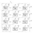
- FIG. 1is a schematic representation of a structure according to an embodiment of the present invention
- FIG. 2is a block diagram showing certain components of a wireless fixture provided within the structure shown in FIG. 1 ;
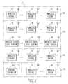
- FIG. 3is a schematic representation of a structure according to an alternative embodiment of the present invention.
- FIG. 1is a schematic representation of a structure 5 according to an embodiment of the present invention.
- the term “structure”shall expressly include, but not be limited by, a home, apartment, dwelling, garage, office building, commercial building, industrial building, of a roofed and/or walled structure built for permanent or temporary use.
- the structure 5may include a number of subdivisions 10 , which may be, without limitation, a floor of the structure 5 or a particular room within the structure 5 .
- each subdivision 10 within the structure 5includes one or more wireless fixtures 15 (shown in greater detail in FIG. 2 and described below).
- a subdivision 10may be a particular floor that includes within it multiple wireless fixtures 15 or, alternatively, a room such as a conference room or storage room, located on a particular floor that includes within it multiple wireless fixtures 15 .
- each wireless fixture 15includes a plurality of light bulbs (or lamps) 20 (and as such is a wireless lighting fixture), which may be any type of known light bulb for providing light such as, without limitation, a fluorescent or incandescent bulb.
- Each wireless fixture 15also includes a processing unit 25 , such as, without limitation, a microprocessor or microcontroller, and a wireless communications device 30 . Together, the processing unit 25 and the wireless communications device 30 form part of what is commonly known as a ballast 35 .
- the wireless communications device 30enables the wireless fixture 15 to wirelessly transmit and receive data (as described elsewhere herein) using a wireless communications protocol.
- the wireless communications protocolmay be any known or hereafter developed protocol such as, without limitation, any of a variety of known RF communications protocols.
- the term “wireless”shall expressly include, but not be limited by, radio frequency (RF), infrared, wireless area networks, IEEE 802.11 (e.g., 802.11a; 802.11b; 802.11g), IEEE 802.15 (e.g., 802.15.1; 802.15.3, 802.15.4), and other wireless communication standards (e.g., without limitation, ZigBeeTM Alliance standard, DECT, PWT, pager, PCS, Wi-Fi, BluetoothTM, and cellular).
- RFradio frequency
- IEEE 802.11e.g., 802.11a; 802.11b; 802.11g
- IEEE 802.15e.g., 802.15.1; 802.15.3, 802.15.4
- other wireless communication standardse.g., without limitation, ZigBeeTM Alliance standard, DECT, PWT, pager, PCS, Wi-Fi, BluetoothTM
- the wireless communications device 30may be a commercially available transceiver (e.g., RF) device or may include a separate commercially available transmitting (e.g., RF) device and a separate commercially available receiving (e.g., RF) device.
- RFradio frequency
- the wireless communications device 30is in electronic communication with the processing unit 25 and, as a result, is able to provide data to and receive data from the processing unit 25 .
- the ballast 35may be independently powered by, for example, a battery (not shown), in which case it is able to function when the bulbs 20 are in an OFF state.
- the ballast 35may be powered via “the mains”, yet still have the ability to turn ON, OFF, and dim the bulbs 20 in the wireless fixture 15 .
- the ballast 35can be in a low power mode, but still have the ability to receive wireless commands and act on them as described herein.
- the ballast 35may also wake up (i.e., leave the low power mode) periodically and broadcast its status to the central controller 45 as described elsewhere herein.
- the processing unit 25is operatively coupled to each light bulb 20 and is able to selectively control the operation of the light bulbs 20 .
- the processing unit 20is able to selectively turn the light bulbs 20 ON and OFF and, preferably, dim the light bulbs 20 by controlling the amount of current that is provided to the light bulbs 20 from a source of power (e.g., the “mains”, not shown).
- the processing unit 25is able to collect various types of operational data relating to the operation of the wireless fixture 15 such as, without limitation, the number of hours (e.g., within a particular time frame) that the bulbs 20 are operational (i.e., turned ON), the energy/power consumed by the wireless fixture 15 (a small meter may be provided in the wireless fixture 15 for this purpose), the number of starts (i.e., moving from an OFF to an ON condition) experienced by the bulbs 20 (e.g., within a particular time frame), and the voltage and/or current consumed by the wireless fixture 15 (e.g., within a particular time frame), among others.
- the processing unit 25is in electronic communication with a memory 40 provided within the ballast 35 for storing such collected data.
- the memory 40also stores the various software routines (which may include one or more subroutines, processes, procedures, function calls or the like, alone or in combination) that are executable by the processing unit 25 for controlling the operation of the wireless fixture 15 as described herein.
- the memory 40can be any of a variety of types of internal and/or external storage media such as, without limitation, RAM, ROM, EEROM's, EEPROM's, and the like, alone or in combination.
- the structure 5also includes a central controller 45 , which may be, without limitation, a suitable computing device having a suitable processor or processing capability such as a PC or server computer.
- the central controller 45includes wireless communications capability.
- the central controller 45is able to selectively wirelessly transmit data to and selectively wirelessly receive data from each of the wireless fixtures 15 provided within the structure 5 through, for example, a wireless communications device that is similar to the wireless communications device 30 .
- each wireless fixture 15may be uniquely identified within the structure 5 , such as by a unique ID number or serial number associated therewith.
- each wireless fixture 15may be separately addressable by the central controller 45 so that the central controller 45 can selectively wirelessly transmit operational commands to each wireless fixture 15 to independently control the operation thereof.
- the operational commandswill be received by the wireless communications device 30 and subsequently provided to the processing unit 25 of the appropriate wireless fixture 15 , which in turn will control the operation of the wireless fixture 15 in an appropriate manner (based on the received operational commands).
- individual and/or selected groups of wireless fixtures 15may be selectively controlled by the central controller 45 .
- the central controller 45by issuing the appropriate operational commands, may cause all (or selected ones) of the wireless fixtures 15 within a particular subdivision 10 of the structure 5 to operate in a certain manner, e.g., to be turned ON, turned OFF, or dimmed at a particular time (for instance, the following is a command that may be issued: turn all light bulbs 20 ON at 70 percent power in those wireless fixtures 15 that are located in conference room #2 at noon).
- portions of or all of the operational data that is collected by the processing unit 25 (and preferably stored in the memory 40 ) of each wireless fixture 15may be periodically wirelessly transmitted to the central controller 45 .
- the central controller 45may store the collected operational data, aggregate and/or analyze the collected operational data, and make maintenance decisions/recommendations (e.g., alerts for actions to be taken by maintenance personnel) relating to selected ones or groups of the wireless fixtures 15 based on the aggregated and/or analyzed operational data that has been collected.
- the central controller 45determines that more than a certain percentage of wireless fixtures is (e.g., 75 percent) in a particular subdivision 10 of the structure 5 have more than a certain number of operational hours, or, alternatively, that a certain number (e.g., 30 percent) of light bulbs 20 in those wireless fixtures 15 are beyond their useful life, then an alert may be provided by the central controller 45 to, for example, a maintenance manager that all of the light bulbs 20 in the wireless fixtures 15 in the subdivision 10 should be replaced. This is advantageous as it is more efficient, and therefore reduces labor and/or maintenance costs, to change a larger number of light bulbs 20 at a single time (even if some of the bulbs still have life remaining) than to do so piece-meal.
- a certain percentage of wireless fixturese.g., 75 percent
- a certain numbere.g., 30 percent
- the central controller 45can, based on the aggregated data, analyze the energy consumed by selected ones or groups of the wireless fixtures 15 and issue operational commands (e.g., turn ON, OFF or dim) aimed at conserving energy to selected ones or groups of the wireless fixtures 15 .
- operational commandse.g., turn ON, OFF or dim
- this same energy consumption informationmay be used to pin-point energy consumption levels to particular selected ones or groups of the wireless fixtures 15 , and operational and/or maintenance decisions/recommendations/schedules (e.g., to replace certain bulbs 20 or wireless fixtures 15 ) may be made by the central controller 45 in response thereto.
- lumen depreciationmay be calculated based on measuring or calculating lumen output from the wireless fixtures 15
- predicted Remaining Useful Life (RUL) of the bulbs 20may be calculated based on information obtained form the ballast 35 by knowing the lamp type of the bulbs 20 in question and the operating conditions relating thereto
- predicted Remaining Useful Life (RUL) of the ballasts 35may be calculated based on the operating conditions relating thereto, including temperature.
- each wireless fixture 15may be independently and separately controlled by the central controller 45 and may independently transmit data to the central controller 45 , the structure 5 may be readily reconfigured on a per-fixture basis as necessary.
- groupings of particular wireless fixtures 15 for the purposes described hereinmay be easily changed without the need to revise the structure 5 . This may be necessary, for example, as tenants within the structure 5 acquire more or less space.
- the various subdivisions 10 within the structure 5may be reconfigured so that a wireless fixture 15 formerly associated with one subdivision 10 may be now associated with another subdivision 10 .
- FIG. 3is a schematic representation of a structure 5 ′ according to an alternate embodiment of the invention.
- the structure 5 ′is similar to the structure 5 shown in FIG. 1 and, as seen in FIG. 3 , includes many of the same components.
- the structure 5 ′differs from the structure 5 in that one or more subdivisions 10 thereof include one or more wireless ambient light level sensors 50 .
- Each ambient light level sensor 50is adapted to measure (and accumulate data relating to) the amount of light entering the structure 5 ′ in the vicinity of the ambient light level sensor 50 .
- Each ambient light level sensor 50is also adapted to wirelessly transmit the light level data it collects to the central controller 45 .
- the central controller 45is able to collect such data from each wireless light level sensor 50 , aggregate the collected data and, based on an analysis of aggregated data wirelessly control the operation of selected ones or groups of wireless fixtures 15 to reduce the light being output thereby (by the bulbs 20 thereof) in order to reduce energy consumption and/or heat generation.
- One advantage of this configurationis that the groups of wireless fixtures 15 that may be controlled in this manner can be completely different than other preselected groups of wireless fixtures 15 that are grouped together for control by, for example, a switch or motion sensor.
- a row of offices along an outside wallmay all have individual room controls, but the first row of wireless fixtures 15 (or selected bulbs 20 therein) may be commanded to reduce light level to 60 percent, the second row of wireless fixtures 15 (or selected bulbs 20 therein) may be commanded to reduce light level to 70 percent, and the third row of wireless fixtures 15 (or selected bulbs therein) may be commanded to reduce light level to 80 percent.
Landscapes
- Engineering & Computer Science (AREA)
- Computer Networks & Wireless Communication (AREA)
- Circuit Arrangement For Electric Light Sources In General (AREA)
Abstract
Description
Claims (12)
Priority Applications (1)
| Application Number | Priority Date | Filing Date | Title |
|---|---|---|---|
| US11/610,070US7859398B2 (en) | 2006-12-13 | 2006-12-13 | System and method for maintaining and controlling a plurality of wireless light fixtures |
Applications Claiming Priority (1)
| Application Number | Priority Date | Filing Date | Title |
|---|---|---|---|
| US11/610,070US7859398B2 (en) | 2006-12-13 | 2006-12-13 | System and method for maintaining and controlling a plurality of wireless light fixtures |
Publications (2)
| Publication Number | Publication Date |
|---|---|
| US20080143273A1 US20080143273A1 (en) | 2008-06-19 |
| US7859398B2true US7859398B2 (en) | 2010-12-28 |
Family
ID=39526312
Family Applications (1)
| Application Number | Title | Priority Date | Filing Date |
|---|---|---|---|
| US11/610,070Active2029-10-27US7859398B2 (en) | 2006-12-13 | 2006-12-13 | System and method for maintaining and controlling a plurality of wireless light fixtures |
Country Status (1)
| Country | Link |
|---|---|
| US (1) | US7859398B2 (en) |
Cited By (28)
| Publication number | Priority date | Publication date | Assignee | Title |
|---|---|---|---|---|
| US20110010019A1 (en)* | 2008-06-25 | 2011-01-13 | HID Laboratories, Inc. | Lighting control system and method |
| US20110305200A1 (en)* | 2009-02-24 | 2011-12-15 | Koninklijke Philips Electronics N.V. | Method of controlling a lighting system |
| US20130006437A1 (en)* | 2008-03-27 | 2013-01-03 | Orion Energy Systems, Inc. | System and method for reducing peak and off-peak electricity demand by monitoring, controlling and metering high intensity fluorescent lighting in a facility |
| US8445826B2 (en) | 2007-06-29 | 2013-05-21 | Orion Energy Systems, Inc. | Outdoor lighting systems and methods for wireless network communications |
| US8586902B2 (en) | 2007-06-29 | 2013-11-19 | Orion Energy Systems, Inc. | Outdoor lighting fixture and camera systems |
| US8729446B2 (en) | 2007-06-29 | 2014-05-20 | Orion Energy Systems, Inc. | Outdoor lighting fixtures for controlling traffic lights |
| US8779340B2 (en) | 2007-06-29 | 2014-07-15 | Orion Energy Systems, Inc. | Lighting fixture control systems and methods |
| US8866582B2 (en) | 2009-09-04 | 2014-10-21 | Orion Energy Systems, Inc. | Outdoor fluorescent lighting fixtures and related systems and methods |
| US8884203B2 (en) | 2007-05-03 | 2014-11-11 | Orion Energy Systems, Inc. | Lighting systems and methods for displacing energy consumption using natural lighting fixtures |
| US8921751B2 (en) | 2007-06-29 | 2014-12-30 | Orion Energy Systems, Inc. | Outdoor lighting fixtures control systems and methods |
| US9146012B2 (en) | 2007-06-29 | 2015-09-29 | Orion Energy Systems, Inc. | Lighting device |
| US9198262B1 (en)* | 2014-05-22 | 2015-11-24 | LIFI Labs, Inc. | Directional lighting system and method |
| US9201145B2 (en) | 2013-10-17 | 2015-12-01 | Globalfoundries Inc. | Object location in three dimensional space using LED lights |
| US9326359B2 (en) | 2014-09-02 | 2016-04-26 | LIFI Labs, Inc. | Lighting system operation management method |
| US9351381B2 (en) | 2008-03-27 | 2016-05-24 | Orion Energy Systems, Inc. | System and method for controlling lighting |
| US9648448B2 (en) | 2014-09-02 | 2017-05-09 | LIFI Labs, Inc. | Power outlet and method of use |
| US9660447B2 (en) | 2012-03-02 | 2017-05-23 | Ideal Industries, Inc. | Connector having wireless control capabilities |
| CN106856634A (en)* | 2015-12-09 | 2017-06-16 | 深圳市新环能科技有限公司 | Underground garage lighting intelligent monitoring and EMS |
| EP3130200A4 (en)* | 2014-04-10 | 2017-10-18 | Cooper Technologies Company | Wireless configuration and diagnostics of airfield lighting fixtures |
| US10375789B2 (en) | 2014-05-22 | 2019-08-06 | LIFI Labs, Inc. | Directional lighting system and method |
| US10440794B2 (en) | 2016-11-02 | 2019-10-08 | LIFI Labs, Inc. | Lighting system and method |
| US10588206B2 (en) | 2013-11-14 | 2020-03-10 | LIFI Labs, Inc. | Resettable lighting system and method |
| US10851950B2 (en) | 2013-10-15 | 2020-12-01 | LIFI Labs, Inc. | Lighting assembly |
| US11219112B2 (en) | 2019-09-09 | 2022-01-04 | Appleton Grp Llc | Connected controls infrastructure |
| US11232684B2 (en) | 2019-09-09 | 2022-01-25 | Appleton Grp Llc | Smart luminaire group control using intragroup communication |
| US11343898B2 (en) | 2019-09-20 | 2022-05-24 | Appleton Grp Llc | Smart dimming and sensor failure detection as part of built in daylight harvesting inside the luminaire |
| US11455884B2 (en) | 2014-09-02 | 2022-09-27 | LIFI Labs, Inc. | Lighting system |
| US20230413409A1 (en)* | 2018-03-06 | 2023-12-21 | Schreder S.A. | Luminaire network with sensors |
Families Citing this family (11)
| Publication number | Priority date | Publication date | Assignee | Title |
|---|---|---|---|---|
| CN101802942A (en) | 2007-01-29 | 2010-08-11 | 普迈公司 | Pinless power coupling |
| US7809963B2 (en)* | 2007-02-12 | 2010-10-05 | Dorn William E | User space power controller |
| US20130208497A1 (en)* | 2010-04-05 | 2013-08-15 | University Of Utah Research Foundation | Infusion line identification lighting system |
| CN103765992B (en)* | 2011-09-02 | 2016-08-17 | 皇家飞利浦有限公司 | Device and method for controlling a node of a wireless network |
| US20150264776A1 (en)* | 2012-09-24 | 2015-09-17 | Petra Solar, Inc. | Distributed street lights energy remote monitoring, command and control |
| US9930741B2 (en) | 2015-02-27 | 2018-03-27 | Xicato, Inc. | Synchronized light control over a wireless network |
| US9788397B2 (en)* | 2015-02-27 | 2017-10-10 | Xicato, Inc. | Lighting communication advertising packets |
| US9930752B2 (en)* | 2015-11-10 | 2018-03-27 | General Electric Company | Image sensor controlled lighting fixture |
| WO2020115528A1 (en)* | 2018-12-05 | 2020-06-11 | Miscato Limited | Liquid diffuser system |
| US20230056443A1 (en)* | 2021-08-21 | 2023-02-23 | Nathalie Boucher | Equine gastric health formulation |
| FR3143168A1 (en)* | 2022-12-07 | 2024-06-14 | Signall Centre France | Remote supervision system for illuminated signs |
Citations (16)
| Publication number | Priority date | Publication date | Assignee | Title |
|---|---|---|---|---|
| US5726644A (en) | 1995-06-30 | 1998-03-10 | Philips Electronics North America Corporation | Lighting control system with packet hopping communication |
| US5848054A (en) | 1996-02-07 | 1998-12-08 | Lutron Electronics Co. Inc. | Repeater for transmission system for controlling and determining the status of electrical devices from remote locations |
| US5898733A (en) | 1995-06-30 | 1999-04-27 | Philips Electronics North America Corporation | Packet hopping system with sliding frequency, and transciever for the system |
| US6340864B1 (en) | 1999-08-10 | 2002-01-22 | Philips Electronics North America Corporation | Lighting control system including a wireless remote sensor |
| US6445691B2 (en) | 1998-06-08 | 2002-09-03 | Koninklijke Philips Electronics N. V. | Wireless coupling of standardized networks and non-standardized nodes |
| US6445690B2 (en) | 1998-06-08 | 2002-09-03 | Koninklijke Philips Electronics N.V. | Wireless coupling of incompatible nodes via a virtual network |
| US6604163B1 (en) | 2000-05-16 | 2003-08-05 | Koninklijke Philips Electronics N.V. | Interconnection of digital signal processor with program memory and external devices using a shared bus interface |
| US6687487B1 (en) | 1996-02-07 | 2004-02-03 | Lutron Electronics, Co., Inc. | Repeater for transmission system for controlling and determining the status of electrical devices from remote locations |
| US6701526B1 (en) | 1999-07-01 | 2004-03-02 | Koninklijke Philips Electronics N.V. | Method and apparatus for capturing broadcast EPG data for program title display |
| US20050154494A1 (en)* | 2003-09-26 | 2005-07-14 | Osman Ahmed | Integrated building environment data system |
| US20070040513A1 (en)* | 2005-06-30 | 2007-02-22 | Cleland Donald A | Method and system for luminance characterization |
| US20070043541A1 (en)* | 2005-06-30 | 2007-02-22 | Cleland Donald A | Method and system for controling a luminaire |
| US20070070571A1 (en)* | 2004-02-24 | 2007-03-29 | Musco Corporation | Apparatus and method for compensating for reduced light output of a light source having a lumen depreciation characteristic over its operational life |
| US20080116826A1 (en)* | 2006-08-28 | 2008-05-22 | Hunter Fan Company | System and method for current and/or temperature control of light fixture |
| US20080228508A1 (en)* | 2007-03-13 | 2008-09-18 | Renaissance Lighting, Inc. | Monitoring connect time and time of operation of a solid state lighting device |
| US7649472B1 (en)* | 2003-10-14 | 2010-01-19 | David Joseph August Paterno | Integrated lighting and detector units |
- 2006
- 2006-12-13USUS11/610,070patent/US7859398B2/enactiveActive
Patent Citations (16)
| Publication number | Priority date | Publication date | Assignee | Title |
|---|---|---|---|---|
| US5898733A (en) | 1995-06-30 | 1999-04-27 | Philips Electronics North America Corporation | Packet hopping system with sliding frequency, and transciever for the system |
| US5726644A (en) | 1995-06-30 | 1998-03-10 | Philips Electronics North America Corporation | Lighting control system with packet hopping communication |
| US6687487B1 (en) | 1996-02-07 | 2004-02-03 | Lutron Electronics, Co., Inc. | Repeater for transmission system for controlling and determining the status of electrical devices from remote locations |
| US5848054A (en) | 1996-02-07 | 1998-12-08 | Lutron Electronics Co. Inc. | Repeater for transmission system for controlling and determining the status of electrical devices from remote locations |
| US6445691B2 (en) | 1998-06-08 | 2002-09-03 | Koninklijke Philips Electronics N. V. | Wireless coupling of standardized networks and non-standardized nodes |
| US6445690B2 (en) | 1998-06-08 | 2002-09-03 | Koninklijke Philips Electronics N.V. | Wireless coupling of incompatible nodes via a virtual network |
| US6701526B1 (en) | 1999-07-01 | 2004-03-02 | Koninklijke Philips Electronics N.V. | Method and apparatus for capturing broadcast EPG data for program title display |
| US6340864B1 (en) | 1999-08-10 | 2002-01-22 | Philips Electronics North America Corporation | Lighting control system including a wireless remote sensor |
| US6604163B1 (en) | 2000-05-16 | 2003-08-05 | Koninklijke Philips Electronics N.V. | Interconnection of digital signal processor with program memory and external devices using a shared bus interface |
| US20050154494A1 (en)* | 2003-09-26 | 2005-07-14 | Osman Ahmed | Integrated building environment data system |
| US7649472B1 (en)* | 2003-10-14 | 2010-01-19 | David Joseph August Paterno | Integrated lighting and detector units |
| US20070070571A1 (en)* | 2004-02-24 | 2007-03-29 | Musco Corporation | Apparatus and method for compensating for reduced light output of a light source having a lumen depreciation characteristic over its operational life |
| US20070040513A1 (en)* | 2005-06-30 | 2007-02-22 | Cleland Donald A | Method and system for luminance characterization |
| US20070043541A1 (en)* | 2005-06-30 | 2007-02-22 | Cleland Donald A | Method and system for controling a luminaire |
| US20080116826A1 (en)* | 2006-08-28 | 2008-05-22 | Hunter Fan Company | System and method for current and/or temperature control of light fixture |
| US20080228508A1 (en)* | 2007-03-13 | 2008-09-18 | Renaissance Lighting, Inc. | Monitoring connect time and time of operation of a solid state lighting device |
Cited By (62)
| Publication number | Priority date | Publication date | Assignee | Title |
|---|---|---|---|---|
| US8884203B2 (en) | 2007-05-03 | 2014-11-11 | Orion Energy Systems, Inc. | Lighting systems and methods for displacing energy consumption using natural lighting fixtures |
| US9521726B2 (en) | 2007-05-03 | 2016-12-13 | Orion Energy Systems, Inc. | Lighting systems and methods for displacing energy consumption using natural lighting fixtures |
| US11026302B2 (en) | 2007-06-29 | 2021-06-01 | Orion Energy Systems, Inc. | Outdoor lighting fixtures control systems and methods |
| US11202355B2 (en) | 2007-06-29 | 2021-12-14 | Orion Energy Systems, Inc. | Outdoor lighting fixture and camera systems |
| US8445826B2 (en) | 2007-06-29 | 2013-05-21 | Orion Energy Systems, Inc. | Outdoor lighting systems and methods for wireless network communications |
| US8586902B2 (en) | 2007-06-29 | 2013-11-19 | Orion Energy Systems, Inc. | Outdoor lighting fixture and camera systems |
| US10206265B2 (en) | 2007-06-29 | 2019-02-12 | Orion Energy Systems, Inc. | Outdoor lighting fixtures control systems and methods |
| US10098213B2 (en) | 2007-06-29 | 2018-10-09 | Orion Energy Systems, Inc. | Lighting fixture control systems and methods |
| US8729446B2 (en) | 2007-06-29 | 2014-05-20 | Orion Energy Systems, Inc. | Outdoor lighting fixtures for controlling traffic lights |
| US8779340B2 (en) | 2007-06-29 | 2014-07-15 | Orion Energy Systems, Inc. | Lighting fixture control systems and methods |
| US10694594B2 (en) | 2007-06-29 | 2020-06-23 | Orion Energy Systems, Inc. | Lighting fixture control systems and methods |
| US10694605B2 (en) | 2007-06-29 | 2020-06-23 | Orion Energy Systems, Inc. | Outdoor lighting fixtures control systems and methods |
| US8921751B2 (en) | 2007-06-29 | 2014-12-30 | Orion Energy Systems, Inc. | Outdoor lighting fixtures control systems and methods |
| US9146012B2 (en) | 2007-06-29 | 2015-09-29 | Orion Energy Systems, Inc. | Lighting device |
| US11432390B2 (en) | 2007-06-29 | 2022-08-30 | Orion Energy Systems, Inc. | Outdoor lighting fixtures control systems and methods |
| US10187557B2 (en) | 2007-06-29 | 2019-01-22 | Orion Energy Systems, Inc. | Outdoor lighting fixture and camera systems |
| US9351381B2 (en) | 2008-03-27 | 2016-05-24 | Orion Energy Systems, Inc. | System and method for controlling lighting |
| US20130006437A1 (en)* | 2008-03-27 | 2013-01-03 | Orion Energy Systems, Inc. | System and method for reducing peak and off-peak electricity demand by monitoring, controlling and metering high intensity fluorescent lighting in a facility |
| US9504133B2 (en) | 2008-03-27 | 2016-11-22 | Orion Energy Systems, Inc. | System and method for controlling lighting |
| US8666559B2 (en)* | 2008-03-27 | 2014-03-04 | Orion Energy Systems, Inc. | System and method for reducing peak and off-peak electricity demand by monitoring, controlling and metering high intensity fluorescent lighting in a facility |
| US9215780B2 (en) | 2008-03-27 | 2015-12-15 | Orion Energy Systems, Inc. | System and method for reducing peak and off-peak electricity demand by monitoring, controlling and metering lighting in a facility |
| US8406937B2 (en) | 2008-03-27 | 2013-03-26 | Orion Energy Systems, Inc. | System and method for reducing peak and off-peak electricity demand by monitoring, controlling and metering high intensity fluorescent lighting in a facility |
| US10334704B2 (en) | 2008-03-27 | 2019-06-25 | Orion Energy Systems, Inc. | System and method for reducing peak and off-peak electricity demand by monitoring, controlling and metering lighting in a facility |
| US20110010019A1 (en)* | 2008-06-25 | 2011-01-13 | HID Laboratories, Inc. | Lighting control system and method |
| US8670873B2 (en)* | 2008-06-25 | 2014-03-11 | Lumetric Lighting, Inc. | Lighting control system and method |
| US20110305200A1 (en)* | 2009-02-24 | 2011-12-15 | Koninklijke Philips Electronics N.V. | Method of controlling a lighting system |
| US9585230B2 (en)* | 2009-02-24 | 2017-02-28 | Philips Lighting Holding B.V. | Method of controlling a lighting system |
| US9523485B2 (en) | 2009-09-04 | 2016-12-20 | Orion Energy Systems, Inc. | Outdoor lighting fixtures and related systems and methods |
| US8866582B2 (en) | 2009-09-04 | 2014-10-21 | Orion Energy Systems, Inc. | Outdoor fluorescent lighting fixtures and related systems and methods |
| US9951933B2 (en) | 2009-09-04 | 2018-04-24 | Orion Energy Systems, Inc. | Outdoor lighting fixtures and related systems and methods |
| US9660447B2 (en) | 2012-03-02 | 2017-05-23 | Ideal Industries, Inc. | Connector having wireless control capabilities |
| US10851950B2 (en) | 2013-10-15 | 2020-12-01 | LIFI Labs, Inc. | Lighting assembly |
| US11359771B2 (en) | 2013-10-15 | 2022-06-14 | LIFI Labs, Inc. | Lighting assembly |
| US9201145B2 (en) | 2013-10-17 | 2015-12-01 | Globalfoundries Inc. | Object location in three dimensional space using LED lights |
| US11985749B2 (en) | 2013-11-14 | 2024-05-14 | Feit Electric Company, Inc. | Resettable lighting system and method |
| US10588206B2 (en) | 2013-11-14 | 2020-03-10 | LIFI Labs, Inc. | Resettable lighting system and method |
| US11632846B2 (en) | 2013-11-14 | 2023-04-18 | Feit Electric Company, Inc. | Resettable lighting system and method |
| US10779385B2 (en) | 2013-11-14 | 2020-09-15 | LIFI Labs, Inc. | Resettable lighting system and method |
| EP3130200A4 (en)* | 2014-04-10 | 2017-10-18 | Cooper Technologies Company | Wireless configuration and diagnostics of airfield lighting fixtures |
| US9635737B2 (en) | 2014-05-22 | 2017-04-25 | LIFI Labs, Inc. | Directional lighting system and method |
| US9883563B2 (en) | 2014-05-22 | 2018-01-30 | LIFI Labs, Inc. | Directional lighting system and method |
| US10375789B2 (en) | 2014-05-22 | 2019-08-06 | LIFI Labs, Inc. | Directional lighting system and method |
| US9198262B1 (en)* | 2014-05-22 | 2015-11-24 | LIFI Labs, Inc. | Directional lighting system and method |
| US10772171B2 (en) | 2014-05-22 | 2020-09-08 | LIFI Labs, Inc. | Directional lighting system and method |
| US9768831B2 (en) | 2014-09-02 | 2017-09-19 | LIFI Labs, Inc. | Power outlet and method for use |
| US10645558B2 (en) | 2014-09-02 | 2020-05-05 | LIFI Labs, Inc. | Power outlet and method for use |
| US11006262B2 (en) | 2014-09-02 | 2021-05-11 | LIFI Labs, Inc. | Power outlet and method for use |
| US9648448B2 (en) | 2014-09-02 | 2017-05-09 | LIFI Labs, Inc. | Power outlet and method of use |
| US11166144B2 (en) | 2014-09-02 | 2021-11-02 | LIFI Labs, Inc. | Power outlet and method for use |
| US12080158B2 (en) | 2014-09-02 | 2024-09-03 | Feit Electric Company, Inc. | Lighting system |
| US11455884B2 (en) | 2014-09-02 | 2022-09-27 | LIFI Labs, Inc. | Lighting system |
| US10136292B2 (en) | 2014-09-02 | 2018-11-20 | LIFI Labs, Inc. | Power outlet and method for use |
| US9326359B2 (en) | 2014-09-02 | 2016-04-26 | LIFI Labs, Inc. | Lighting system operation management method |
| CN106856634A (en)* | 2015-12-09 | 2017-06-16 | 深圳市新环能科技有限公司 | Underground garage lighting intelligent monitoring and EMS |
| US11425802B2 (en) | 2016-11-02 | 2022-08-23 | LIFI Labs, Inc. | Lighting system and method |
| US10952296B2 (en) | 2016-11-02 | 2021-03-16 | LIFI Labs, Inc. | Lighting system and method |
| US10440794B2 (en) | 2016-11-02 | 2019-10-08 | LIFI Labs, Inc. | Lighting system and method |
| US20230413409A1 (en)* | 2018-03-06 | 2023-12-21 | Schreder S.A. | Luminaire network with sensors |
| US12150224B2 (en)* | 2018-03-06 | 2024-11-19 | Schreder S.A. | Luminaire network with sensors |
| US11232684B2 (en) | 2019-09-09 | 2022-01-25 | Appleton Grp Llc | Smart luminaire group control using intragroup communication |
| US11219112B2 (en) | 2019-09-09 | 2022-01-04 | Appleton Grp Llc | Connected controls infrastructure |
| US11343898B2 (en) | 2019-09-20 | 2022-05-24 | Appleton Grp Llc | Smart dimming and sensor failure detection as part of built in daylight harvesting inside the luminaire |
Also Published As
| Publication number | Publication date |
|---|---|
| US20080143273A1 (en) | 2008-06-19 |
Similar Documents
| Publication | Publication Date | Title |
|---|---|---|
| US7859398B2 (en) | System and method for maintaining and controlling a plurality of wireless light fixtures | |
| US11402861B2 (en) | Wireless load control system | |
| US20230072726A1 (en) | Systems and methods for controlling color temperature | |
| US20250309681A1 (en) | Load Control System Having Independently-Controlled Units Responsive To A Broadcast Controller | |
| US9167408B2 (en) | Methods and apparatus for identifying and categorizing distributed devices | |
| US7948189B2 (en) | Application of microsystems for lighting control | |
| CN106937459B (en) | Method, system and apparatus for providing variable illumination | |
| KR20080084920A (en) | Wireless building automation and control networks, digital ballasts, and wireless control devices | |
| WO2011142830A2 (en) | Apparatus and methods for controlling light fixtures and electrical appliances | |
| US20140148923A1 (en) | Apparatus and methods for controlling light fixtures and electrical apparatus | |
| US10524335B1 (en) | Systems and methods for reducing network traffic in a lighting system | |
| US20220095084A1 (en) | Transmission of control data on wireless network communication links | |
| US20180177026A1 (en) | Space scoring for a lighting network | |
| CN107490133A (en) | Appliances equipment control method and system, Intelligent illumination device, air-conditioning | |
| KR101182599B1 (en) | Apparatus and method for controlling of power consumption appliance | |
| JP2017022058A (en) | Led illumination system | |
| JP2017021932A (en) | Led illumination system | |
| US11532403B2 (en) | Microcontroller for IoT GaN power devices and mesh network comprising one or more microcontroller controlled IoT GaN devices | |
| KR101576975B1 (en) | Lighting central control system | |
| KR20130120360A (en) | Apparatus and method for controlling of power consumption appliance | |
| KR20150006642A (en) | Control system for lighting lamp having dimming control function and method for controlling the same | |
| CN221175255U (en) | Energy consumption device control system | |
| HK40008825B (en) | Load control system having independently-controlled units responsive to a broadcast controller | |
| HK1261634A1 (en) | Load control system having independently-controlled units responsive to a broadcast controller | |
| HK1261634B (en) | Load control system having independently-controlled units responsive to a broadcast controller |
Legal Events
| Date | Code | Title | Description |
|---|---|---|---|
| AS | Assignment | Owner name:EATON CORPORATION, OHIO Free format text:ASSIGNMENT OF ASSIGNORS INTEREST;ASSIGNORS:DAVIDSON, DAVID L.;LUEBKE, CHARLES J.;REEL/FRAME:018625/0446;SIGNING DATES FROM 20061208 TO 20061212 Owner name:EATON CORPORATION, OHIO Free format text:ASSIGNMENT OF ASSIGNORS INTEREST;ASSIGNORS:DAVIDSON, DAVID L.;LUEBKE, CHARLES J.;SIGNING DATES FROM 20061208 TO 20061212;REEL/FRAME:018625/0446 | |
| FEPP | Fee payment procedure | Free format text:PAYOR NUMBER ASSIGNED (ORIGINAL EVENT CODE: ASPN); ENTITY STATUS OF PATENT OWNER: LARGE ENTITY | |
| STCF | Information on status: patent grant | Free format text:PATENTED CASE | |
| FPAY | Fee payment | Year of fee payment:4 | |
| MAFP | Maintenance fee payment | Free format text:PAYMENT OF MAINTENANCE FEE, 8TH YEAR, LARGE ENTITY (ORIGINAL EVENT CODE: M1552) Year of fee payment:8 | |
| AS | Assignment | Owner name:EATON INTELLIGENT POWER LIMITED, IRELAND Free format text:ASSIGNMENT OF ASSIGNORS INTEREST;ASSIGNOR:EATON CORPORATION;REEL/FRAME:048855/0626 Effective date:20171231 | |
| MAFP | Maintenance fee payment | Free format text:PAYMENT OF MAINTENANCE FEE, 12TH YEAR, LARGE ENTITY (ORIGINAL EVENT CODE: M1553); ENTITY STATUS OF PATENT OWNER: LARGE ENTITY Year of fee payment:12 |