US7857843B2 - Differentially expanded vascular graft - Google Patents
Differentially expanded vascular graftDownload PDFInfo
- Publication number
- US7857843B2 US7857843B2US11/026,777US2677704AUS7857843B2US 7857843 B2US7857843 B2US 7857843B2US 2677704 AUS2677704 AUS 2677704AUS 7857843 B2US7857843 B2US 7857843B2
- Authority
- US
- United States
- Prior art keywords
- portions
- ptfe tube
- longitudinal
- tube
- microstructures
- Prior art date
- Legal status (The legal status is an assumption and is not a legal conclusion. Google has not performed a legal analysis and makes no representation as to the accuracy of the status listed.)
- Expired - Fee Related, expires
Links
Images


Classifications
- A—HUMAN NECESSITIES
- A61—MEDICAL OR VETERINARY SCIENCE; HYGIENE
- A61F—FILTERS IMPLANTABLE INTO BLOOD VESSELS; PROSTHESES; DEVICES PROVIDING PATENCY TO, OR PREVENTING COLLAPSING OF, TUBULAR STRUCTURES OF THE BODY, e.g. STENTS; ORTHOPAEDIC, NURSING OR CONTRACEPTIVE DEVICES; FOMENTATION; TREATMENT OR PROTECTION OF EYES OR EARS; BANDAGES, DRESSINGS OR ABSORBENT PADS; FIRST-AID KITS
- A61F2/00—Filters implantable into blood vessels; Prostheses, i.e. artificial substitutes or replacements for parts of the body; Appliances for connecting them with the body; Devices providing patency to, or preventing collapsing of, tubular structures of the body, e.g. stents
- A61F2/02—Prostheses implantable into the body
- A61F2/04—Hollow or tubular parts of organs, e.g. bladders, tracheae, bronchi or bile ducts
- A61F2/06—Blood vessels
- A—HUMAN NECESSITIES
- A61—MEDICAL OR VETERINARY SCIENCE; HYGIENE
- A61L—METHODS OR APPARATUS FOR STERILISING MATERIALS OR OBJECTS IN GENERAL; DISINFECTION, STERILISATION OR DEODORISATION OF AIR; CHEMICAL ASPECTS OF BANDAGES, DRESSINGS, ABSORBENT PADS OR SURGICAL ARTICLES; MATERIALS FOR BANDAGES, DRESSINGS, ABSORBENT PADS OR SURGICAL ARTICLES
- A61L27/00—Materials for grafts or prostheses or for coating grafts or prostheses
- A61L27/14—Macromolecular materials
- A61L27/16—Macromolecular materials obtained by reactions only involving carbon-to-carbon unsaturated bonds
- A—HUMAN NECESSITIES
- A61—MEDICAL OR VETERINARY SCIENCE; HYGIENE
- A61L—METHODS OR APPARATUS FOR STERILISING MATERIALS OR OBJECTS IN GENERAL; DISINFECTION, STERILISATION OR DEODORISATION OF AIR; CHEMICAL ASPECTS OF BANDAGES, DRESSINGS, ABSORBENT PADS OR SURGICAL ARTICLES; MATERIALS FOR BANDAGES, DRESSINGS, ABSORBENT PADS OR SURGICAL ARTICLES
- A61L27/00—Materials for grafts or prostheses or for coating grafts or prostheses
- A61L27/50—Materials characterised by their function or physical properties, e.g. injectable or lubricating compositions, shape-memory materials, surface modified materials
- A61L27/507—Materials characterised by their function or physical properties, e.g. injectable or lubricating compositions, shape-memory materials, surface modified materials for artificial blood vessels
- B—PERFORMING OPERATIONS; TRANSPORTING
- B29—WORKING OF PLASTICS; WORKING OF SUBSTANCES IN A PLASTIC STATE IN GENERAL
- B29C—SHAPING OR JOINING OF PLASTICS; SHAPING OF MATERIAL IN A PLASTIC STATE, NOT OTHERWISE PROVIDED FOR; AFTER-TREATMENT OF THE SHAPED PRODUCTS, e.g. REPAIRING
- B29C55/00—Shaping by stretching, e.g. drawing through a die; Apparatus therefor
- B29C55/005—Shaping by stretching, e.g. drawing through a die; Apparatus therefor characterised by the choice of materials
- B—PERFORMING OPERATIONS; TRANSPORTING
- B29—WORKING OF PLASTICS; WORKING OF SUBSTANCES IN A PLASTIC STATE IN GENERAL
- B29C—SHAPING OR JOINING OF PLASTICS; SHAPING OF MATERIAL IN A PLASTIC STATE, NOT OTHERWISE PROVIDED FOR; AFTER-TREATMENT OF THE SHAPED PRODUCTS, e.g. REPAIRING
- B29C55/00—Shaping by stretching, e.g. drawing through a die; Apparatus therefor
- B29C55/22—Shaping by stretching, e.g. drawing through a die; Apparatus therefor of tubes
- B—PERFORMING OPERATIONS; TRANSPORTING
- B29—WORKING OF PLASTICS; WORKING OF SUBSTANCES IN A PLASTIC STATE IN GENERAL
- B29K—INDEXING SCHEME ASSOCIATED WITH SUBCLASSES B29B, B29C OR B29D, RELATING TO MOULDING MATERIALS OR TO MATERIALS FOR MOULDS, REINFORCEMENTS, FILLERS OR PREFORMED PARTS, e.g. INSERTS
- B29K2027/00—Use of polyvinylhalogenides or derivatives thereof as moulding material
- B29K2027/12—Use of polyvinylhalogenides or derivatives thereof as moulding material containing fluorine
- B29K2027/18—PTFE, i.e. polytetrafluorethene, e.g. ePTFE, i.e. expanded polytetrafluorethene
- B—PERFORMING OPERATIONS; TRANSPORTING
- B29—WORKING OF PLASTICS; WORKING OF SUBSTANCES IN A PLASTIC STATE IN GENERAL
- B29K—INDEXING SCHEME ASSOCIATED WITH SUBCLASSES B29B, B29C OR B29D, RELATING TO MOULDING MATERIALS OR TO MATERIALS FOR MOULDS, REINFORCEMENTS, FILLERS OR PREFORMED PARTS, e.g. INSERTS
- B29K2105/00—Condition, form or state of moulded material or of the material to be shaped
- B29K2105/04—Condition, form or state of moulded material or of the material to be shaped cellular or porous
- B—PERFORMING OPERATIONS; TRANSPORTING
- B29—WORKING OF PLASTICS; WORKING OF SUBSTANCES IN A PLASTIC STATE IN GENERAL
- B29K—INDEXING SCHEME ASSOCIATED WITH SUBCLASSES B29B, B29C OR B29D, RELATING TO MOULDING MATERIALS OR TO MATERIALS FOR MOULDS, REINFORCEMENTS, FILLERS OR PREFORMED PARTS, e.g. INSERTS
- B29K2105/00—Condition, form or state of moulded material or of the material to be shaped
- B29K2105/24—Condition, form or state of moulded material or of the material to be shaped crosslinked or vulcanised
- B29K2105/246—Uncured, e.g. green
- B—PERFORMING OPERATIONS; TRANSPORTING
- B29—WORKING OF PLASTICS; WORKING OF SUBSTANCES IN A PLASTIC STATE IN GENERAL
- B29L—INDEXING SCHEME ASSOCIATED WITH SUBCLASS B29C, RELATING TO PARTICULAR ARTICLES
- B29L2031/00—Other particular articles
- B29L2031/753—Medical equipment; Accessories therefor
- B29L2031/7532—Artificial members, protheses
- B29L2031/7534—Cardiovascular protheses
Definitions
- the present inventionrelates generally to a vascular graft formed of polytetrafluoroethylene (PTFE). More specifically, the present invention relates to such a vascular graft having longitudinally expanded portions distributed longitudinally along the graft, where the longitudinal expansion of the portions differs such that the microstructure of the graft varies longitudinally along the length thereof. Also, the present invention relates to a method and apparatus for making the vascular graft.
- PTFEpolytetrafluoroethylene
- PTFEpolytetrafluoroethylene
- PTFEpolytetrafluoroethylene
- ePTFEexpanded polytetrafluoroethylene
- Grafts formed of ePTFEhave a fibrous state which is defined by interspaced nodes interconnected by elongated fibrils. The spaces between the node surfaces that is spanned by the fibrils is defined as the internodal distance (IND).
- INDinternodal distance
- a graft having a large INDmay enhance tissue ingrowth and cell endothelization by a significant portion of the graft having interior voids some of which provide passages through the tube wall between the outer and inner surfaces thereof. This provides the graft with porosity.
- Microporous ePTFE tubes for use as vascular graftsare known.
- the porosity of an ePTFE vascular graftmay be controllably varied by controllably varying the IND.
- an increase in the ND within a given structuremay result in an increased porosity, i.e., increased pore size, by increasing the distance between nodes resulting in thinning of the fibrils. This, in turn, results in larger voids, i.e., pores, in the ePTFE material.
- Increased porositytypically enhances tissue ingrowth as well as cell endothelization along the inner and outer surface of the ePTFE tube.
- Increasing the porosity of an ePTFE tubemay limit other properties of the tube. For example, increasing the porosity of the tube may reduce the overall radial and tensile strength thereof as well as reduce the ability of the graft to retain a suture placed in the tube during implantation. Such a suture typically extends through the wall of the graft. Also, such microporous tubes tend to exhibit low axial tear strength, so that a small tear or nick will tend to propagate along the length of the tube. Thus, if the ePTFE tube has a uniform porosity along its length, the degree of porosity of therein may be limited by the strength requirements of the tube.
- the strength requirements for the PTFE tubemay be satisfied by selected longitudinal sections of the tube having the required strength, then it may be possible for other longitudinal sections of the tube to have an elevated porosity, even if such other longitudinal sections have limited strength.
- selected axial portions of the ePTFE tubemay have sufficient stiffness to prevent kinking. Such stiffness may be provided by increasing the stiffness of such axial portions where such axial portions have an annular cross-section and accordingly, the shape of individual rings. Such axial portions may typically be spaced apart from one another longitudinally and nevertheless provide the necessary stiffness to the vascular graft. Therefore, the portions of the graft between stiffened axial portions may have a lower requirement for strength and may therefore have a higher porosity.
- vascular graft having increased requirements for strengthis where such one or more portions are to be pierced for insertion of a suture therethrough. If the portion of the graft to be pierced can be identified just prior to the piercing, then other longitudinal sections of the graft may have lower strength requirements and therefore have a higher porosity.
- Another possible technique for increasing the radial tensile and axial tear strength of microporous ePTFE tubesis to modify the structure of the extruded PTFE tubing during formation so that the resulting expanded tube has non-longitudinally aligned fibrils.
- Forming an expanded PTFE tube with non-longitudinally aligned fibrilsis typically difficult as it may require extrusion of the tube using complex equipment before expansion of the tube.
- Other possible methods for forming non-longitudinally aligned fibrilswould be expected to be complex.
- Additional propertiesmay be desirably varied along the length of a ePTFE tube.
- Another property of an ePTFE tube which may desirably be varied along the length thereofis the number and thickness of the fibrils connecting individual nodes. This property may also be related to porosity because increasing the number and thickness of such fibrils may reduce the size of the voids in the ePTFE tube and thereby reduce the porosity thereof. Accordingly, if the number and thickness of fibrils is not reduced by an increase in the IND, then such an increase may not result in an increased porosity of the ePTFE tube.
- a further property of an ePTFE tube which may be desirably varied along the length thereofis the length of the fibrils connecting individual nodes. Increasing the length of the fibrils increases the flexibility of the ePTFE tube, even if the number and thickness of the fibrils is not changed.
- a possible technique for varying the properties of an ePTFE along the length thereofmay include longitudinally expanding the entire tube and then longitudinally compressing selected axial portions thereof. Such longitudinal compression typically results in a decrease in the IND, and decreased porosity in the compressed axial portions. Also, such longitudinal compression typically results in bending or folding of the fibrils. Also, the microstructure resulting therefrom differs significantly from the node and fibril microstructure which would be caused by longitudinal expansion of the axial portion to the same axial dimension as results from the longitudinal compression.
- the differentially expanded vascular graft of the present inventionis for implantation within a body.
- the vascular graftincludes a PTFE tube formed of a homogeneous material.
- the PTFE tubehas a longitudinal first portion which has been longitudinally expanded, and a longitudinal second portion which has been longitudinally expanded.
- the first and second portionshave respective microstructures which are different from one another.
- a method and apparatus for making the differentially expanded vascular graft of the present inventionfacilitates the formation of the various expanded portions of the PTFE tube.
- One of the characteristics of the microstructures of the first and second portions which may be differentare the respective INDs for the portions. This, in turn, typically results in other properties of the first and second portions being different, such as porosity, permeability, density or strength. This enables the formation of a vascular graft selected portions of which have respective properties, the combination of which may be difficult to provide in a single graft made according to conventional techniques.
- a single graft of the present inventionmay have some portions with high porosity and other portions with low porosity.
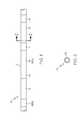
- FIG. 1is a side elevational view of the differentially expanded vascular graft of the present invention, the graft having annular portions which have been expanded longitudinally by different amounts;
- FIG. 2is a longitudinal cross-sectional view of the differentially expanded vascular graft of FIG. 1 in the plane indicated by line 3 - 3 of FIG. 1 ;
- FIG. 3is a generalized schematic view of an alternative embodiment of the differentially expanded vascular graft of FIG. 1 , the graft having annular expanded portions which have different microstructures;
- FIG. 4is a block diagram showing a method for making a differentially expanded vascular graft of the present invention, the method including longitudinally expanding the respective portions of the vascular graft by different amounts;
- FIG. 5is a block diagram showing an alternative method for making a differentially expanded vascular graft of FIG. 4 , the method including expanding the respective portions of the vascular graft and verifying the corresponding microstructures of the portions;
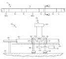
- FIG. 6is a schematic diagram showing an apparatus for making a differentially expanded vascular graft of the present invention, the apparatus including a pair of clamps for expanding an intermediate portion of the extrudate.
- vascular graft 10for implantation within a body.
- the vascular graft 10includes a PTFE tube 12 formed of homogeneous material.
- the tube 12has longitudinal first and second portions 14 , 16 in alternating relation as shown in FIG. 1 .
- the first and second portions 14 , 16have been longitudinally expanded by different amounts.
- the first portions 14have each been longitudinally expanded such that the lengths thereof increase by 200%.
- the second portions 16have each been longitudinally expanded such that the lengths thereof increase by 600%.
- the respective amounts of the expansion of the first and second portions 14 , 16result in the PTFE material of the first portions 14 having generally the same microstructures and the PTFE material of the second portions 16 having generally the same microstructure. Further, the different amounts of expansion result in the microstructures of the first portions 14 being different from the microstructures of the second portions 16 .
- the microstructures of the first and second portions 14 , 16may be locked by sintering thereof.
- the first and second portions 14 , 16 of the PTFE tube 12each have annular cross-sections such that each portion has a ring-shape, as shown in FIG. 2 .
- the respective outer and inner diameters of each of the portions 14 , 16are the same.
- the respective lengths of the portions 14 , 16are different.
- the respective longitudinal expansions which provide the lengths of the portions 14 , 16may constitute the complete longitudinal expansion of the PTFE tube 12 such that the length thereof after the respective longitudinal expansions is the target length.
- the first and second portions 14 , 16may be expanded by amounts other than the 200% and 600% of FIG. 1 .
- the PTFE tube 12may have additional longitudinal portions which are expanded by further differing amounts.
- FIG. 3A generalized schematic view of an alternative embodiment of the vascular graft 20 is shown in FIG. 3 .
- the vascular graft 20includes a PTFE tube 22 formed of homogeneous material and having longitudinal first, second, and third portions 25 , 27 , 29 which have different microstructures. While the microstructures differ, the chemical composition of the portions 25 , 27 , 29 are the same thereby making the material of the PTFE tube 22 homogeneous.
- the different microstructures of the portions 25 , 27 , 29result from respective longitudinal expansions thereof.
- the desired microstructures of the portions 25 , 27 , 29 of the PTFE tube 22may be locked by sintering thereof.
- the different microstructures of the portions 25 , 27 , 29 of the PTFE tube 22each have a fibrous state which is defined by interspaced nodes which are interconnected by elongated fibrils, referred to herein as a “node and fibril microstructure”.
- the distance between adjacent nodes which is spanned by the fibrilsis defined as the internodal distance (IND).
- the microstructures of the portions 25 , 27 , 29each have corresponding INDs which differ according to the differences in the respective microstructures.
- the INDs for the corresponding portions 25 , 27 , 29are indicated by the suffixes ( 25 ), ( 27 ), ( 29 ) in FIG. 3 .
- the node and fibril microstructureincludes spaces between the outer surfaces of the nodes and fibers which provide the microstructure with pores. Typically, these pores result in porosity which typically increases with increasing IND ( 25 ), ( 27 ), ( 29 ) because a large IND normally provides greater flexibility of fibers to increase porosity. It is possible to have a relatively larger IND ( 25 ), ( 27 ), ( 29 ) with a relatively large number or thickness of fibrils between the nodes. This would also increase the length of the fibrils which would result in greater flexibility thereof and increased porosity.
- the microstructures of the portions 25 , 27 , 29each have corresponding pore sizes which differ according to the differences in the respective microstructures.
- the pore sizesmay be indicated by across areas which are the areas of the pores included in defined areas of a plane which is perpendicular to a radius of the PTFE tube 22 .
- the respective across areas for the portions 25 , 27 , 29therefore differ from one another according to the differences in pore sizes.
- the across areas for the corresponding portions 25 , 27 , 29are indicated by the suffixes ( 25 ), ( 27 ), ( 29 ) in FIG. 3 .
- the respective node and fibril microstructuresmay differ by the size and shape of the nodes.
- a microstructure having large nodeshas fewer fibrils and a microstructure having small nodes has more fibrils.
- Expansion of the PTFE tube 22normally produces nodes which are smaller because material is transferred therefrom to the fibrils to provide increased length of the fibrils.
- the thickness of the fibrilsremains generally constant during such expansion.
- Expansion of PTFEsuch as by 200%, may produce microstructures having small or large nodes, long or short fibrils, and different numbers of fibrils and nodes, such that these characteristics of the microstructure are normally independent of the expansion percentage.
- nodes which are relatively largenormally limit the size of the pores since the relatively large nodes limit the space available in the tube wall for the pores. Conversely, relatively small nodes typically result in increased pore sizes.
- the shape of the nodesmay affect the microstructure, such as by providing an external surface which affects the connection of the fibrils to the nodes. For example, nodes having a relatively large, uniform outer surface area may facilitate connection of the fibrils thereto, including the connection of large numbers of fibrils or fibrils having a relatively large thickness. Also, the shape of the nodes may be sufficiently uniform to enable the extension of fibrils therefrom in various directions.
- Groups of the pores within the node and fibril microstructure of the PTFE tube 22are typically interconnected to provide passageways, which are typically tortuous and partially non-radial, through the respective tube walls of the portions 25 , 27 , 29 between the inner and outer surfaces thereof.
- Thisprovides the portions 25 , 27 , 29 with respective porosities and permeabilities allowing gas and liquid to flow through the respective tube walls of the portions 25 , 27 , 29 between the inner and outer surfaces thereof.
- Such flow of gas or liquidtypically occurs during test conditions when the pressure of the gas or liquid is elevated.
- fluiddoes not flow through the walls of the portions 25 , 27 , 29 .
- the porosities and permeabilitiesmay be different for the respective portions 25 , 27 , 29 depending upon the resistance to gas and liquid flow through the respective tube walls.
- the porosities and permeabilities for the corresponding portions 25 , 27 , 29are indicated by the suffixes ( 25 ), ( 27 ) ( 29 ) in FIG. 3 .
- the different permeabilities in the portions 25 , 27 , 29result in the respective portions having different permeation rates, indicated by the suffixes ( 25 ), ( 27 ), ( 29 ) in FIG. 3 .
- the permeation ratesare the respective speeds with which a gas, such as air, or liquid flows through a corresponding wall of the portions 25 , 27 , 29 .
- Using a liquid to measure the permeability of the portions 25 , 27 , 29may result in the liquid directing forces against the portions which exceed the strength thereof.
- Using a gas to measure the permeability of the portions 25 , 27 , 29normally results in the gas directing forces against the portions which are below the strength thereof.
- the different node and fibril microstructuresmay also result in the portions 25 , 27 , 29 of the PTFE tube 22 having different densities.
- the densities of corresponding portions 25 , 27 , 29are indicated by the suffixes ( 25 ), ( 27 ), ( 29 ) in FIG. 3 .
- the density of the portions 25 , 27 , 29is typically inversely related to the spaces between the nodes and fibrils. This results from spaces between the nodes and fibrils reducing the amount of PTFE material present in a specific portion of the PTFE tube 22 .
- the different node and fibril microstructuresmay also result in the portions 25 , 27 , 29 of the PTFE tube 22 having different tensile strengths, and different circumferential hoop strengths. These tensile strengths and circumferential hoop strengths for the corresponding portions 25 , 27 , 29 are indicated by the suffixes ( 25 ), ( 27 ), ( 29 ) in FIG. 3 .
- the strength of the PTFE tube 22 following longitudinal expansion thereofmay also be related to porosity since high porosity may result in low strength of the PTFE tube because the pores or spaces therein do not contain material which may provide strength to the PTFE tube. Conversely, low porosity may result in high strength of the PTFE tube 22 .
- Other aspects of the PTFE tube 22 which affect the strength thereofmay be affected by the longitudinal expansion of the PTFE tube.
- the direction of the expansion of the PTFE tube 22may produce a node and fibril microstructure in which the fibrils thereof have a specific orientation such as longitudinal, radial or inclination therebetween which may have a corresponding effect on the tensile or circumferential hoop strength of the PTFE tube.
- the ability to expand the PTFE tube 22 in a radial directionmay be limited, although such expansion may be produced in the PTFE tube 22 by supplying air having an elevated pressure to the internal region thereof.
- Biaxial expansion of the PTFE tube 22such as contemporaneous longitudinal and radial expansion thereof, is possible by supplying air having an elevated pressure to the internal region of the PTFE tube 22 during the longitudinal expansion of the PTFE tube. It is normally required to hold the expansion of the PTFE tube 22 physically, such as by clamping the ends of the expanded portions, before the sintering thereof.
- the differences in the node and fibril microstructuresmay include differences in the respective fibril thicknesses for the portion 25 , 27 , 29 of the PTFE tube 22 .
- the fibril thicknessesare the total thicknesses of all of the fibrils connected between adjacent nodes of respective microstructures.
- the fibril thicknesses for the corresponding portions 25 , 27 , 29are indicated by the suffixes ( 25 ), ( 27 ), ( 29 ) in FIG. 3 .
- These differencesmay affect various properties of the respective node and fibril microstructures, including porosity, across area, permeability, density, and strength.
- the portions 25 , 27 , 29 of the PTFE tube 22each may have annular cross-sections such that each portion has a ring-shape.
- the respective outer and inner diameters of each of the portions 25 , 27 , 29may each be the same.
- the respective lengths of the portions 25 , 27 , 29may be substantially different.
- the respective longitudinal expansions which provide the lengths of the portions 25 , 27 , 29may constitute the complete longitudinal expansion of the PTFE tube 22 such that the length thereof after the respective longitudinal expansions is the target length.
- a method 30 for making the first and second portions 14 , 16 of the vascular graft 10is represented by the block diagram of FIG. 4 .
- the method 30includes providing 31 an un-sintered PTFE green tube extrudate 12 , including the first and second portions 14 , 16 , formed of homogeneous material.
- the homogeneous material of the PTFE tube 12is provided by a material having a uniform chemical composition.
- the method 30further includes longitudinally expanding 32 the green tube extrudate 12 , including all of the first and second portions 14 , 16 , such that the lengths of each of the first and second portions increases by 200%.
- the first portions 14are each sintered 33 to lock the microstructures and prevent further expansion thereof.
- the method 32further includes longitudinally expanding 34 the green tube extrudate 12 , including all of the first and second portions 14 , 16 , such that the lengths of each of the second portions increases by 600%.
- the sintering 33 of the first portions 14prevents further expansion thereof such that the expansion 34 does not produce further significant expansion of the first portions. As a result, the expansion of the first portions 14 of 200% is not significantly changed by the expansion 34 .
- the method 32includes sintering 35 the green tube extrudate 12 , including all of the first and second portions 14 , 16 , to lock the microstructures of the second portions 16 and prevent further expansion thereof.
- sintering 35the green tube extrudate 12 , including all of the first and second portions 14 , 16 , to lock the microstructures of the second portions 16 and prevent further expansion thereof.
- Inclusion of the first portions 14 in the sintering 33is not required since the microstructures of the first portions 14 were previously locked by the sintering 33 .
- inclusion of the first portions 14 in the sintering 35simplifies the performance thereof since sintering of the second portions 16 , without sintering the first portions 14 , is not required. This enables a single sintering process to be used contemporaneously for each of the first and second portions 14 , 16 , such as by heating the entire tube 12 in an oven.
- the respective microstructures of the portions 25 , 27 , 29may be produced according to the method 36 represented by the block diagram of FIG. 5 .
- the method 36includes providing 37 a PTFE tube 22 , including the portions 25 , 27 , 29 , formed of homogeneous material.
- the homogeneous material of the PTFE tube 22is provided by a material having a uniform chemical composition.
- the provision 37 of the PTFE tube 22may include the PTFE tube being an un-sintered green tube extrudate.
- the method 36further includes performing respective longitudinal expansions 38 , 39 , 41 of the portions 25 , 27 , 29 of the PTFE tube 22 to produce corresponding microstructures therein.
- the longitudinal expansions 38 , 39 , 41produce respective microstructures in the portions 25 , 27 , 29 such that the microstructures are different.
- the differences in the microstructuresmay be produced by the longitudinal expansions 38 , 39 , 41 producing different percentage increases of the corresponding portions 25 , 27 , 29 of the PTFE tube 22 .
- the percentage increases produced by the corresponding longitudinal expansions 38 , 39 , 41are indicated by the suffixes ( 38 ), ( 39 ), ( 41 ) in FIG. 5 .
- the percentage increases ( 38 ), ( 39 ), ( 41 )are the proportional increases in length of the portions 25 , 27 , 29 produced by the associated longitudinal expansions 38 , 39 , 41 .
- the proportional increaseis relative to the length of the respective portion 25 , 27 , 29 just before the associated longitudinal expansion 38 , 39 , 41 .
- the differences in the microstructuresmay result from longitudinally expanding 38 , 39 , 41 the portions 25 , 27 , 29 according to different stretch rates.
- the stretch rates of the respective longitudinal expansions 37 , 39 , 41are indicated by the suffixes ( 38 ), ( 39 ), ( 41 ) in FIG. 5 .
- the stretch rates ( 38 ), ( 39 ), ( 41 )are the respective increases in the length of the portions 25 , 27 , 29 divided by the corresponding time periods during which the respective lengths are increased.
- the longitudinal expansions 38 , 39 , 41 at different stretch rates ( 38 ), ( 39 ), ( 41 )may result in different percentage increases ( 38 ), ( 39 ), ( 41 ) in the portions 25 , 27 , 29 , or generally the same percentage increases.
- Such percentage increases ( 38 ), ( 39 ), ( 41 )will be affected by the duration of the respective expansions 38 , 39 , 41 and the lengths of the portions 25 , 27 , 29 before the expansions.
- the differences in the microstructuresmay be produced by heating 43 , 45 , 47 the portions 25 , 27 , 29 to different temperatures shortly before the respective expansions 38 , 39 , 41 .
- This heating 43 , 45 , 47 of each of the portions 25 , 27 , 29is timed to be before the corresponding expansions 38 , 39 , 41 .
- the differences in the microstructuresmay be produced by heating 50 , 52 , 54 the portions 25 , 27 , 29 to different temperatures during the respective expansions 38 , 39 , 41 . These temperatures applied to each of the portions 25 , 27 , 29 are timed to be during the corresponding expansions 38 , 39 , 41 .
- portions 25 , 27 , 29may be heated both shortly before 43 , 45 , 47 and during 50 , 52 , 54 the respective expansions 38 , 39 , 41 to produce the different micro structures.
- the method 36further includes measuring 57 respective characteristics of the microstructures of the portions 25 , 27 , 29 which result from the respective expansions 38 , 39 , 41 .
- This measuring 57may be performed by a device which generates measurement signals 59 indicative of the respective measured characteristics.
- the devicemay provide a visual display based on the generation of the measurement signals 59 for direct viewing by a user who may determine therefrom whether the measured characteristics are the same as or sufficiently close to a reference indicative of acceptable microstructures. The user may alternatively determine, from viewing the visual display, that one or more of the measured characteristics are neither the same as nor sufficiently close to the reference to be acceptable.
- the generation of the measurement signals 59may provide electrical signals for transmission to an electronic processor, such as a microprocessor of a computer.
- an electronic processormay be programmed to compare the measurement signals to the reference 61 and generate an acceptability signal 63 for those measurement signals which are the same as or sufficiently close to the reference.
- the electronic processormay be further programmed to generate a non-acceptability signal 65 for those measurements signals which are neither the same as nor sufficiently close to the reference.
- the electronic processoris connected to a display device for receiving the acceptability or non-acceptability signals from the electronic processor and to communicate to the user whether the respective characteristics measured for the portions 25 , 27 , 29 are acceptable.
- One of the characteristics of the microstructures of the portions 25 , 27 , 29 which may be measured 57are the respective INDs of the portions 25 , 27 , 29 .
- the INDs measured in each of the portions 25 , 27 , 29are indicated by the suffixes ( 25 ), ( 27 ), ( 29 ) in FIG. 5 .
- microstructures of the portions 25 , 27 , 29which may be measured 57 are the respective permeation rates of the portions 25 , 27 , 29 .
- the permeation rates measured in each of the portions 25 , 27 , 29are indicated by the suffixes ( 25 ), ( 27 ), ( 29 ) in FIG. 5 .
- a further alternative characteristic of the microstructures of the portions 25 , 27 , 29 which may be measured 57are the respective tensile strengths of the portions 25 , 27 , 29 .
- the tensile strengths measured in each of the portions 25 , 27 , 29are indicated by the suffixes ( 25 ), ( 27 ), ( 29 ) in FIG. 5 .
- a further alternative characteristic of the microstructures of the portions 25 , 27 , 29 which may be measured 57are the respective circumferential hoop strengths of the portions 25 , 27 , 29 .
- the circumferential hoop strengths measured in each of the portions 25 , 27 , 29are indicated by the suffixes ( 25 ), ( 27 ), ( 29 ) in FIG. 5 .
- the method 36includes sintering each of the portions 25 , 27 , 29 of the PTFE tube 22 following the corresponding expansions 38 , 39 , 41 thereof to lock the respective microstructures. It may be preferred for the sintering 67 to follow the determinations that the microstructures of the respective portions 25 , 27 , 29 are acceptable, such as by following the generation of the acceptability signals 63 . This provides for the performance of further heating 43 , 45 , 47 and/or further expansions and heating 38 , 39 , 41 of one or more of the portions 25 , 27 , 29 , if necessary, to produce acceptable microstructures therein before the sintering 79 , 81 , 83 thereof, as indicated by the reference numeral 69 in FIG. 5 .
- Such further processingmay be followed by measurements of the characteristics 57 of the portions 25 , 27 , 29 on which such further processing was performed, as indicated by the reference numeral 70 in FIG. 5 .
- Such measurements 57 , and the subsequent comparisons to the reference 61indicate whether acceptable microstructures in the portions 25 , 27 , 29 have been obtained or whether more of such further processing is required. This provides for possible iterations to produce acceptable microstructures which, once obtained, are then sintered 67 for locking thereof.
- the sintering 67is preferably performed as shortly thereafter as possible to lock the acceptable microstructures and prevent any unintended changes in the microstructures which, if sufficient, could result in the microstructures becoming unacceptable.
- the microstructuresmay change after the expansions 38 , 39 , 41 and before the sintering 67 as a result of retraction of the portions 25 , 27 , 29 .
- Such retractionmay be prevented by forcibly retaining the portions 25 , 27 , 29 in their expanded dimension, such as by grasping the ends of the portions, after expansion, by clamps or retaining rings. Such grasping may, however, leave an imprint on the portions 25 , 27 , 29 which may be undesirable. The extent of such an imprint may be lessened by the sintering 67 being soon after the expansions 38 , 39 , 41 .
- the retractionis also possible for the retraction to be limited by the contact between the portions 25 , 27 , 29 and the outer surface of the mandrel on which the PTFE tube 23 may be supported during the processing thereof.
- Such limitation of the retractiontypically requires the contact between the PTFE tube 23 and the outer surface of the mandrel to prevent longitudinal translation of the PTFE tube relative thereto.
- Such prevention of longitudinal translationmay be provided, for example, by the inner surface of the PTFE tube 23 being sticky.
- the PTFE tube 23is required to be prevented from retraction by some type of restraint after expansion and before sintering 67 . Otherwise, at least some retraction and resultant redistribution of the node and fibril microstructure may be expected.
- each of the portions 25 , 27 , 29 of the PTFE tube 22can be sintered shortly after each of the corresponding expansions 38 , 39 , 41 and before the measurements 57 of the respective microstructures of the portions 25 , 27 , 29 .
- Such sinteringsare indicated by the reference numerals 71 , 73 , 75 and by broken lines to signify an alternative to the sintering 67 .
- a PTFE tube 22 in which the microstructure is not acceptable in at least one of the portions 25 , 27 , 29would likely be discarded since further alteration of such a microstructure for acceptability thereof, such as by further expansions 38 , 39 , 41 and/or heating 43 , 45 , 47 , 50 , 52 , 54 of the portions 25 , 27 , 29 , may be limited as a result of the sintering.
- Sintering before the measurements of the respective microstructures of the portions 25 , 27 , 29may be advantageous, if acceptable microstructures therein are produced after the initial expansions 38 , 39 , 41 and/or heating 43 , 45 , 47 , 50 , 52 , 54 of the portions 25 , 27 , 29 , by reducing the opportunity for undesirable alteration of the microstructures which could possibly occur before or during the measurements of the microstructures 57 and associated determinations of the acceptability thereof 61 , 63 , 65 .
- the method 36may include performing different longitudinal expansions 38 , 39 , 41 on the respective portions 25 , 27 , 29 of the PTFE tube 22 to produce different microstructures therein.
- Differences in the physical characteristics of the portions 25 , 27 , 29 before the expansions 38 , 39 , 41may be provided by different microstructures, which may be due to different INDs, or dimensions, such as the different thicknesses of the portions 25 , 27 , 29 .
- differences in the physical characteristicsmay be provided by pre-sintering sections of the portions 25 , 27 , 29 , such as in the shape of circumferential rings or elongate longitudinal sections, before the expansions 38 , 39 , 41 .
- pre-sintering sections of the portions 25 , 27 , 29such as in the shape of circumferential rings or elongate longitudinal sections, before the expansions 38 , 39 , 41 . Examples of such pre-sintering are disclosed in the U.S. Patent Application filed in the USPTO on even date herewith and titled “Sintered Ring Supported Vascular Graft”, having as the inventors Jamie Henderson and Dennis Kujawski, and the application Ser. No. 11/026,748.
- Such differences in the physical characteristics of the portions 25 , 27 , 29may be present in a PTFE tube 22 formed of homogeneous material since such a tube may have the same chemical composition while the portions 25 , 27 , 29 thereof differ in one or more of the physical characteristics.
- the apparatus 80includes a base 82 and a support fixture 84 mounted thereon.
- the support fixture 84provides support for a PTFE tube 86 , which may be a green tube extrudate.
- the support fixture 84may include a mandrel on which the PTFE tube 86 may be supported.
- the apparatus 80further includes a first clamp 88 which is mounted on the base 82 .
- the first clamp 88is able to grip the PTFE tube 86 at a longitudinal first position 90 along the length thereof such that the first clamp is longitudinally fixed to the PTFE tube.
- the first position 90is between the ends of the PTFE tube 86 .
- the apparatus 80further includes a second clamp 91 mounted on the base 82 .
- the second clamp 91is able to grip a longitudinal second position 92 along the length of the PTFE tube 86 such that the second clamp is longitudinally fixed thereto.
- the second position 92is between the ends of the PTFE tube 86 .
- the first and second clamps 88 , 91may be longitudinally displaced in opposite longitudinal directions 94 each of which is parallel to the longitudinal axis of the PTFE tube 86 when the PTFE tube is supported by the support fixture 84 . Such longitudinal displacement of the first and second clamps 88 , 91 increases the distance therebetween in the longitudinal direction 94 .
- the apparatus 80provides for such displacement of the first and second clamps 88 , 91 in the longitudinal directions 94 when the PTFE tube 86 is supported by the support fixture 84 and gripped between the first and second clamps. This results in longitudinal expansion of the portion of the PTFE tube 86 which is gripped between the first and second clamps 88 , 91 .
- the apparatus 80may have either the first or second clamp 88 , 91 fixed relative to the base 82 to prevent longitudinal displacement of the fixed one of the first and second clamps when the PTFE tube 86 is supported by the support fixture 84 and the PTFE tube is gripped by the first and second clamps.
- the other of the first or second clamps 88 , 91may be longitudinally displaced in the longitudinal direction 94 to increase the distance between the first and second clamps in the longitudinal direction. This results in the longitudinal expansion of the portion of the PTFE tube 86 which is gripped between the first and second clamps 88 , 91 .
- the apparatus 80includes a displacement controller 96 connected to the first and second clamps 88 , 91 for control of the respective longitudinal displacements thereof.
- the displacement controller 96produces specific longitudinal displacements of the first and second clamps 88 , 91 resulting in a corresponding longitudinal expansion of a specific amount in the portion of the PTFE tube 86 which is gripped between the first and second clamps.
- the displacement controller 96may be adjustable to provide for variable longitudinal displacements of the first and second clamps 88 , 91 to longitudinally expand by corresponding specific amounts the portion of the PTFE tube 86 which is gripped between the first and second clamps.
- the displacement controller 96may provide for control of the speed of the longitudinal displacement of the first and second clamps 88 , 91 such that the longitudinal displacement produces a corresponding stretch rate of longitudinal expansion of the portion of the PTFE tube 86 which is gripped between the first and second clamps.
- the stretch rateis defined as the increase in the length of the portion of the PTFE tube 86 which is gripped between the first and second clamps 88 , 91 divided by the corresponding time period during which the length is increased.
- the displacement controller 96may be adjustable to provide for variable speeds of longitudinal displacement of the first and second clamps 88 , 91 to longitudinally expand by corresponding specific stretch rates the portion of the PTFE tube 86 which is gripped between the first and second clamps.
- the displacement controller 96is connected to the other of the clamps which may be longitudinally displaced to longitudinally expand the portion of the PTFE tube 86 which is gripped between the first and second clamps.
- the displacement controller 96may thereby provide adjustable control of both the specific amount of the longitudinal expansion of the portion of the PTFE tube 86 which is gripped between the first and second clamps, and the stretch rate of the longitudinal expansion.
- the apparatus 80includes an energy source 98 mounted on the base 82 in proximity to the portion of the PTFE tube 86 which is gripped between the first and second clamps 88 , 91 when the PTFE tube is supported by the support fixture 84 .
- the energy source 98is thermally coupled to the portion of the PTFE tube 86 between the first and second clamps 88 , 91 to transfer heat to the portion of the PTFE tube.
- the energy source 98is positioned relative to the PTFE tube 86 to enable the thermal coupling and resultant transfer of heat to the PTFE tube before and/or during the expansion thereof.
- the energy source 98also provides for control of the timing of the transfer of heat to the PTFE tube 86 to provide for the transfer of heat before and/or during the expansion of the PTFE tube.
- the apparatus 80includes a temperature controller 100 connected to the energy source 98 .
- the temperature controller 100provides for control of the heat transferred from the energy source 98 to the portion of the PTFE tube 86 between the first and second clamps 88 , 91 to control the temperature of the portion of the PTFE tube before and/or during the expansion thereof.
- the temperature controller 100may be adjustable to provide for variation of the temperature of the portion of the PTFE tube 86 between the first and second clamps 88 , 91 before and/or during the expansion of the PTFE tube.
- the apparatus 80includes a detector 102 having a sensor 104 for measuring a characteristic of the microstructure in the portion of the PTFE tube 86 which is gripped between the first and second clamps 88 , 91 .
- the detector 102has an output device 106 connected to the sensor 104 .
- the output device 106generates a measurement signal which indicates the characteristic measured by the sensor 104 .
- the apparatus 80further includes a comparator 108 connected to the output device 106 .
- the comparator 108receives the measurement signal from the output device 106 and compares the measurement signal to a reference, which indicates an acceptable measurement of the characteristic.
- the comparator 108generates an acceptability signal if the measurement signal is the same as or sufficiently close to the reference.
- the comparator 108generates a non-acceptability signal if the measurement signal is neither the same as nor sufficiently close to the reference.
- the sensor 104may be of various types for measuring various characteristics of the microstructure in the portion of the PTFE tube 86 which is gripped between the first and second clamps 88 , 91 .
- the sensor 104may be able to measure the IND in the portion of the PTFE tube 86 after the longitudinal expansion thereof.
- the INDis the distance between adjacent nodes of the node and fibril microstructure which results from the longitudinal expansion of the portion of the PTFE tube 86 which is gripped between the first and second clamps 88 , 91 .
- the senor 104may be able to measure the permeation rate in the portion of the PTFE tube 86 after the longitudinal expansion thereof.
- the permeation rateis the speed with which a gas flows through a wall of the portion of the PTFE tube 86 .
- the gas flowresults from pores in the portion of the PTFE tube 86 .
- the senor 104may be able to measure the strength, such as the tensile strength or circumferential hoop strength, of the portion of the PTFE tube 86 after the longitudinal expansion thereof.
- the apparatus 80may be used to longitudinally expand additional longitudinal portions of the PTFE tube 86 by moving the first and second clamps 88 , 91 to other specific longitudinal positions along the PTFE tube and operating the apparatus as described in the foregoing.
- the apparatus 80may be operated to longitudinally expand at least two longitudinal portions of the PTFE tube 86 . Where two such longitudinal portions of the PTFE tube 86 are expanded using the apparatus 80 , one end of each such portion may be coincident with or adjacent to one of the ends of the PTFE tube 86 .
- either the first or second positions 90 , 92may be coincident with or adjacent to one of the ends of the PTFE tube 86 .
Landscapes
- Health & Medical Sciences (AREA)
- Life Sciences & Earth Sciences (AREA)
- Public Health (AREA)
- Animal Behavior & Ethology (AREA)
- Oral & Maxillofacial Surgery (AREA)
- Transplantation (AREA)
- Engineering & Computer Science (AREA)
- Chemical & Material Sciences (AREA)
- Veterinary Medicine (AREA)
- General Health & Medical Sciences (AREA)
- Dermatology (AREA)
- Vascular Medicine (AREA)
- Medicinal Chemistry (AREA)
- Epidemiology (AREA)
- Mechanical Engineering (AREA)
- Pulmonology (AREA)
- Gastroenterology & Hepatology (AREA)
- Heart & Thoracic Surgery (AREA)
- Biomedical Technology (AREA)
- Chemical Kinetics & Catalysis (AREA)
- Cardiology (AREA)
- Prostheses (AREA)
- Materials For Medical Uses (AREA)
Abstract
Description
Claims (4)
Priority Applications (6)
| Application Number | Priority Date | Filing Date | Title |
|---|---|---|---|
| US11/026,777US7857843B2 (en) | 2004-12-31 | 2004-12-31 | Differentially expanded vascular graft |
| PCT/US2005/047206WO2006073974A1 (en) | 2004-12-31 | 2005-12-28 | Differentially expanded vascular graft |
| JP2007549579AJP4818277B2 (en) | 2004-12-31 | 2005-12-28 | Vascular grafts with different degrees of expansion |
| CA002603098ACA2603098A1 (en) | 2004-12-31 | 2005-12-28 | Differentially expanded vascular graft |
| AT05857231TATE530964T1 (en) | 2004-12-31 | 2005-12-28 | DIFFERENTIALLY EXPANDED VASCULAR IMPLANT |
| EP05857231AEP1834221B1 (en) | 2004-12-31 | 2005-12-28 | Differentially expanded vascular graft |
Applications Claiming Priority (1)
| Application Number | Priority Date | Filing Date | Title |
|---|---|---|---|
| US11/026,777US7857843B2 (en) | 2004-12-31 | 2004-12-31 | Differentially expanded vascular graft |
Publications (2)
| Publication Number | Publication Date |
|---|---|
| US20060155371A1 US20060155371A1 (en) | 2006-07-13 |
| US7857843B2true US7857843B2 (en) | 2010-12-28 |
Family
ID=36168924
Family Applications (1)
| Application Number | Title | Priority Date | Filing Date |
|---|---|---|---|
| US11/026,777Expired - Fee RelatedUS7857843B2 (en) | 2004-12-31 | 2004-12-31 | Differentially expanded vascular graft |
Country Status (6)
| Country | Link |
|---|---|
| US (1) | US7857843B2 (en) |
| EP (1) | EP1834221B1 (en) |
| JP (1) | JP4818277B2 (en) |
| AT (1) | ATE530964T1 (en) |
| CA (1) | CA2603098A1 (en) |
| WO (1) | WO2006073974A1 (en) |
Cited By (9)
| Publication number | Priority date | Publication date | Assignee | Title |
|---|---|---|---|---|
| US20110125255A1 (en)* | 2005-04-13 | 2011-05-26 | Trivascular, Inc. | Ptfe layers and methods of manufacturing |
| US8728372B2 (en) | 2005-04-13 | 2014-05-20 | Trivascular, Inc. | PTFE layers and methods of manufacturing |
| US9358140B1 (en) | 2009-11-18 | 2016-06-07 | Aneuclose Llc | Stent with outer member to embolize an aneurysm |
| US9907684B2 (en) | 2013-05-08 | 2018-03-06 | Aneuclose Llc | Method of radially-asymmetric stent expansion |
| US10028747B2 (en) | 2008-05-01 | 2018-07-24 | Aneuclose Llc | Coils with a series of proximally-and-distally-connected loops for occluding a cerebral aneurysm |
| US10213287B2 (en) | 2014-05-16 | 2019-02-26 | Veosource Sa | Implantable self-cleaning blood filters |
| US10426593B2 (en) | 2015-03-11 | 2019-10-01 | Arizona Board Of Regents On Behalf Of The University Of Arizona | Expansible cardiovascular graft system |
| US10716573B2 (en) | 2008-05-01 | 2020-07-21 | Aneuclose | Janjua aneurysm net with a resilient neck-bridging portion for occluding a cerebral aneurysm |
| US11246699B2 (en) | 2017-07-18 | 2022-02-15 | Cook Medical Technologies Llc | Flexible stent with non-bonded stent cover material regions |
Families Citing this family (10)
| Publication number | Priority date | Publication date | Assignee | Title |
|---|---|---|---|---|
| US20060149363A1 (en)* | 2005-01-06 | 2006-07-06 | Scimed Life Systems, Inc. | Optimally expanded, collagen sealed ePTFE graft with improved tissue ingrowth |
| US8025693B2 (en)* | 2006-03-01 | 2011-09-27 | Boston Scientific Scimed, Inc. | Stent-graft having flexible geometries and methods of producing the same |
| US7666496B2 (en)* | 2006-05-24 | 2010-02-23 | Boston Scientific Scimed, Inc. | Micro-sintered node ePTFE structure |
| US20090048657A1 (en)* | 2007-08-15 | 2009-02-19 | Boston Scientific Scimed, Inc. | Preferentially varying-density ePTFE structure |
| US7785363B2 (en)* | 2007-08-15 | 2010-08-31 | Boston Scientific Scimed, Inc. | Skewed nodal-fibril ePTFE structure |
| US20090252926A1 (en)* | 2008-04-03 | 2009-10-08 | Boston Scientific Scimed, Inc. | Thin-walled calendered ptfe |
| US20090319034A1 (en)* | 2008-06-19 | 2009-12-24 | Boston Scientific Scimed, Inc | METHOD OF DENSIFYING ePTFE TUBE |
| US10161727B2 (en) | 2010-11-16 | 2018-12-25 | Aldila Golf Corporation | High straightness arrow and method of manufacture |
| US9448045B2 (en) | 2010-11-16 | 2016-09-20 | Aldila Golf Corp. | High straightness arrow and method of manufacture |
| WO2012074546A2 (en)* | 2010-11-16 | 2012-06-07 | Aldila Golf Corporation | High straightness arrow and method of manufacture |
Citations (103)
| Publication number | Priority date | Publication date | Assignee | Title |
|---|---|---|---|---|
| US3640984A (en) | 1963-11-04 | 1972-02-08 | Allied Chem | Polytetrafluoroethylene |
| US3664915A (en) | 1969-10-03 | 1972-05-23 | Gore & Ass | Sealing material |
| SU468796A1 (en) | 1973-04-20 | 1975-04-30 | Предприятие П/Я А-1385 | The method of obtaining filtering polytetrafluoroethylene film |
| US3953566A (en) | 1970-05-21 | 1976-04-27 | W. L. Gore & Associates, Inc. | Process for producing porous products |
| US3962153A (en) | 1970-05-21 | 1976-06-08 | W. L. Gore & Associates, Inc. | Very highly stretched polytetrafluoroethylene and process therefor |
| GB1506432A (en) | 1974-04-02 | 1978-04-05 | Gore & Ass | Prosthetic device |
| US4096227A (en) | 1973-07-03 | 1978-06-20 | W. L. Gore & Associates, Inc. | Process for producing filled porous PTFE products |
| US4101984A (en) | 1975-05-09 | 1978-07-25 | Macgregor David C | Cardiovascular prosthetic devices and implants with porous systems |
| US4208745A (en)* | 1976-01-21 | 1980-06-24 | Sumitomo Electric Industries, Ltd. | Vascular prostheses composed of polytetrafluoroethylene and process for their production |
| US4281669A (en) | 1975-05-09 | 1981-08-04 | Macgregor David C | Pacemaker electrode with porous system |
| US4304010A (en) | 1978-10-12 | 1981-12-08 | Sumitomo Electric Industries, Ltd. | Tubular polytetrafluoroethylene prosthesis with porous elastomer coating |
| US4454249A (en) | 1981-08-28 | 1984-06-12 | Junkosha Co., Ltd. | Reinforced plastics with porous resin fragments |
| US4459252A (en) | 1975-05-09 | 1984-07-10 | Macgregor David C | Method of forming a small bore flexible vascular graft involving eluting solvent-elutable particles from a polymeric tubular article |
| US4576608A (en) | 1980-11-06 | 1986-03-18 | Homsy Charles A | Porous body-implantable polytetrafluoroethylene |
| US4647416A (en) | 1983-08-03 | 1987-03-03 | Shiley Incorporated | Method of preparing a vascular graft prosthesis |
| US4713070A (en)* | 1978-11-30 | 1987-12-15 | Sumitom Electric Industries, Ltd. | Porous structure of polytetrafluoroethylene and process for production thereof |
| US4743480A (en) | 1986-11-13 | 1988-05-10 | W. L. Gore & Associates, Inc. | Apparatus and method for extruding and expanding polytetrafluoroethylene tubing and the products produced thereby |
| US4816339A (en) | 1987-04-28 | 1989-03-28 | Baxter International Inc. | Multi-layered poly(tetrafluoroethylene)/elastomer materials useful for in vivo implantation |
| US4822341A (en) | 1987-11-20 | 1989-04-18 | Impra, Inc. | Vascular access fistula |
| US4849285A (en) | 1987-06-01 | 1989-07-18 | Bio Med Sciences, Inc. | Composite macrostructure of ceramic and organic biomaterials |
| US4902423A (en) | 1989-02-02 | 1990-02-20 | W. L. Gore & Associates, Inc. | Highly air permeable expanded polytetrafluoroethylene membranes and process for making them |
| US4957669A (en) | 1989-04-06 | 1990-09-18 | Shiley, Inc. | Method for producing tubing useful as a tapered vascular graft prosthesis |
| US4973609A (en) | 1988-11-17 | 1990-11-27 | Memron, Inc. | Porous fluoropolymer alloy and process of manufacture |
| US4975669A (en) | 1989-02-27 | 1990-12-04 | David Sarnoff Research Center, Inc. | Magnetic bottle employing Meissner effect |
| US5024671A (en) | 1988-09-19 | 1991-06-18 | Baxter International Inc. | Microporous vascular graft |
| US5071609A (en) | 1986-11-26 | 1991-12-10 | Baxter International Inc. | Process of manufacturing porous multi-expanded fluoropolymers |
| US5141522A (en) | 1990-02-06 | 1992-08-25 | American Cyanamid Company | Composite material having absorbable and non-absorbable components for use with mammalian tissue |
| US5192310A (en) | 1991-09-16 | 1993-03-09 | Atrium Medical Corporation | Self-sealing implantable vascular graft |
| JPH0584292A (en)* | 1991-09-27 | 1993-04-06 | Jinkou Ketsukan Gijutsu Kenkyu Center:Kk | Artificial blood vessel and production thereof |
| US5207960A (en) | 1990-05-30 | 1993-05-04 | Compagnie Plastic Omnium | Method for the manufacture of thin tubes of fluorinated resin, particularly of polytetrafluoroethylene |
| US5433909A (en) | 1992-03-13 | 1995-07-18 | Atrium Medical Corporation | Method of making controlled porosity expanded polytetrafluoroethylene products |
| US5449373A (en) | 1994-03-17 | 1995-09-12 | Medinol Ltd. | Articulated stent |
| US5462781A (en) | 1991-06-14 | 1995-10-31 | W. L. Gore & Associates, Inc. | Surface modified porous expanded polytetrafluoroethylene and process for making |
| US5607478A (en) | 1996-03-14 | 1997-03-04 | Meadox Medicals Inc. | Yarn wrapped PTFE tubular prosthesis |
| US5609624A (en) | 1993-10-08 | 1997-03-11 | Impra, Inc. | Reinforced vascular graft and method of making same |
| US5620763A (en) | 1993-08-18 | 1997-04-15 | W. L. Gore & Associates, Inc. | Thin-wall, seamless, porous polytetrafluoroethylene tube |
| US5628786A (en) | 1995-05-12 | 1997-05-13 | Impra, Inc. | Radially expandable vascular graft with resistance to longitudinal compression and method of making same |
| US5641373A (en) | 1995-04-17 | 1997-06-24 | Baxter International Inc. | Method of manufacturing a radially-enlargeable PTFE tape-reinforced vascular graft |
| US5643309A (en) | 1993-03-25 | 1997-07-01 | Myler; Richard | Cardiovascular stent and retrieval apparatus |
| US5716660A (en) | 1994-08-12 | 1998-02-10 | Meadox Medicals, Inc. | Tubular polytetrafluoroethylene implantable prostheses |
| US5718973A (en) | 1993-08-18 | 1998-02-17 | W. L. Gore & Associates, Inc. | Tubular intraluminal graft |
| US5733303A (en) | 1994-03-17 | 1998-03-31 | Medinol Ltd. | Flexible expandable stent |
| US5735892A (en) | 1993-08-18 | 1998-04-07 | W. L. Gore & Associates, Inc. | Intraluminal stent graft |
| US5747128A (en) | 1996-01-29 | 1998-05-05 | W. L. Gore & Associates, Inc. | Radially supported polytetrafluoroethylene vascular graft |
| US5749880A (en) | 1995-03-10 | 1998-05-12 | Impra, Inc. | Endoluminal encapsulated stent and methods of manufacture and endoluminal delivery |
| US5800512A (en) | 1996-01-22 | 1998-09-01 | Meadox Medicals, Inc. | PTFE vascular graft |
| US5824042A (en) | 1996-04-05 | 1998-10-20 | Medtronic, Inc. | Endoluminal prostheses having position indicating markers |
| US5824050A (en) | 1996-12-03 | 1998-10-20 | Atrium Medical Corporation | Prosthesis with in-wall modulation |
| US5840775A (en) | 1992-06-25 | 1998-11-24 | E. I. Du Pont De Nemours And Company | Porous polytetraflouroethylene and preparation |
| US5858556A (en) | 1997-01-21 | 1999-01-12 | Uti Corporation | Multilayer composite tubular structure and method of making |
| US5897587A (en) | 1996-12-03 | 1999-04-27 | Atrium Medical Corporation | Multi-stage prosthesis |
| US5928279A (en) | 1996-07-03 | 1999-07-27 | Baxter International Inc. | Stented, radially expandable, tubular PTFE grafts |
| US5972018A (en) | 1994-03-17 | 1999-10-26 | Medinol Ltd. | Flexible expandable stent |
| US5976192A (en) | 1995-06-07 | 1999-11-02 | Baxter International Inc. | Method of forming an externally supported tape reinforced vascular graft |
| US6004348A (en) | 1995-03-10 | 1999-12-21 | Impra, Inc. | Endoluminal encapsulated stent and methods of manufacture and endoluminal delivery |
| US6010529A (en) | 1996-12-03 | 2000-01-04 | Atrium Medical Corporation | Expandable shielded vessel support |
| US6016848A (en) | 1996-07-16 | 2000-01-25 | W. L. Gore & Associates, Inc. | Fluoropolymer tubes and methods of making same |
| US6039755A (en) | 1997-02-05 | 2000-03-21 | Impra, Inc., A Division Of C.R. Bard, Inc. | Radially expandable tubular polytetrafluoroethylene grafts and method of making same |
| GB0003387D0 (en) | 2000-02-14 | 2000-04-05 | Angiomed Ag | Stent matrix |
| US6048360A (en) | 1997-03-18 | 2000-04-11 | Endotex Interventional Systems, Inc. | Methods of making and using coiled sheet graft for single and bifurcated lumens |
| US6053943A (en) | 1995-12-08 | 2000-04-25 | Impra, Inc. | Endoluminal graft with integral structural support and method for making same |
| US6132457A (en) | 1997-10-22 | 2000-10-17 | Triad Vascular Systems, Inc. | Endovascular graft having longitudinally displaceable sections |
| US6146414A (en) | 1997-12-19 | 2000-11-14 | Gelman; Martin L. | Medical graft and construction of the same |
| US6187054B1 (en) | 1999-02-04 | 2001-02-13 | Endomed Inc. | Method of making large diameter vascular prosteheses and a vascular prosthesis made by said method |
| US6203735B1 (en) | 1997-02-03 | 2001-03-20 | Impra, Inc. | Method of making expanded polytetrafluoroethylene products |
| US6214039B1 (en) | 1995-08-24 | 2001-04-10 | Impra, Inc., A Subsidiary Of C. R. Bard, Inc. | Covered endoluminal stent and method of assembly |
| US6231598B1 (en) | 1997-09-24 | 2001-05-15 | Med Institute, Inc. | Radially expandable stent |
| US6245101B1 (en) | 1999-05-03 | 2001-06-12 | William J. Drasler | Intravascular hinge stent |
| US6264684B1 (en) | 1995-03-10 | 2001-07-24 | Impra, Inc., A Subsidiary Of C.R. Bard, Inc. | Helically supported graft |
| US6283991B1 (en) | 1995-12-01 | 2001-09-04 | Medtronics Inc. | Endoluminal prostheses and therapies for highly variable body lumens |
| US20010020181A1 (en) | 1999-02-02 | 2001-09-06 | Richard Layne | Partial encapsulation of stents using strips and bands |
| US6306162B1 (en) | 1999-12-15 | 2001-10-23 | Advanced Cardiovascular Systems, Inc. | Stent delivery system utilizing novel balloon for obtaining variable post-deployment stent characteristics |
| US6319279B1 (en) | 1999-10-15 | 2001-11-20 | Edwards Lifesciences Corp. | Laminated self-sealing vascular access graft |
| US6334867B1 (en) | 1995-09-08 | 2002-01-01 | Anson Medical Ltd | Surgical graft/stent system |
| US6355063B1 (en) | 2000-01-20 | 2002-03-12 | Impra, Inc. | Expanded PTFE drug delivery graft |
| US6364900B1 (en) | 1999-07-14 | 2002-04-02 | Richard R. Heuser | Embolism prevention device |
| US20020042645A1 (en) | 1996-07-03 | 2002-04-11 | Shannon Donald T. | Drug eluting radially expandable tubular stented grafts |
| US6371981B1 (en) | 1998-05-06 | 2002-04-16 | Av Healing Llc | Vascular graft assemblies and methods for implanting same |
| US20020052649A1 (en) | 2000-10-31 | 2002-05-02 | Greenhalgh E. Skott | Graft having region for biological seal formation |
| US6402779B1 (en) | 1999-07-26 | 2002-06-11 | Endomed, Inc. | Balloon-assisted intraluminal stent graft |
| US6416537B1 (en) | 1996-12-03 | 2002-07-09 | Atrium Medical Corporation | Multi-stage prosthesis |
| US6428571B1 (en) | 1996-01-22 | 2002-08-06 | Scimed Life Systems, Inc. | Self-sealing PTFE vascular graft and manufacturing methods |
| US20020111667A1 (en) | 2000-11-02 | 2002-08-15 | Scimed Life Systems, Inc. | Non-expanded porous polytetrafluoroethylene (PTFE) products and methods of manufacture |
| US20020115986A1 (en) | 2000-09-11 | 2002-08-22 | Shadduck John H. | Endovascular medical devices and techniques for delivering therapeutic agents |
| US6451047B2 (en) | 1995-03-10 | 2002-09-17 | Impra, Inc. | Encapsulated intraluminal stent-graft and methods of making same |
| US6488701B1 (en) | 1998-03-31 | 2002-12-03 | Medtronic Ave, Inc. | Stent-graft assembly with thin-walled graft component and method of manufacture |
| US20020198588A1 (en) | 1999-01-22 | 2002-12-26 | Armstrong Joseph R. | Covered endoprosthesis and delivery system |
| US20030017775A1 (en) | 2001-06-11 | 2003-01-23 | Scimed Life Systems. Inc.. | Composite ePTFE/textile prosthesis |
| US6579314B1 (en) | 1995-03-10 | 2003-06-17 | C.R. Bard, Inc. | Covered stent with encapsulated ends |
| US6582463B1 (en) | 2000-10-11 | 2003-06-24 | Heartstent Corporation | Autoanastomosis |
| US20030135265A1 (en) | 2002-01-04 | 2003-07-17 | Stinson Jonathan S. | Prostheses implantable in enteral vessels |
| US20030135266A1 (en) | 2001-12-03 | 2003-07-17 | Xtent, Inc. | Apparatus and methods for delivery of multiple distributed stents |
| US20030211258A1 (en) | 2002-05-13 | 2003-11-13 | Srinivasan Sridharan | Method of making a catheter balloon by laser fusing wrapped material |
| US6699276B2 (en) | 1996-09-26 | 2004-03-02 | Scimed Life Systems, Inc. | Support structure/membrane composite medical device |
| US20040106975A1 (en) | 2001-03-20 | 2004-06-03 | Gmp/Cardiac Care, Inc. | Rail stent |
| US6805706B2 (en) | 2002-08-15 | 2004-10-19 | Gmp Cardiac Care, Inc. | Stent-graft with rails |
| US20050027347A1 (en) | 2001-12-20 | 2005-02-03 | Trivascular, Inc. | Endovascular graft joint and method for manufacture |
| US20050283220A1 (en)* | 2004-06-22 | 2005-12-22 | Gobran Riad H | Blood flow diverters for the treatment of intracranial aneurysms |
| US6994723B1 (en) | 2003-05-21 | 2006-02-07 | Advanced Cardiovascular Systems, Inc. | Medical device made from self-stiffening composite |
| US7011682B2 (en) | 2000-01-31 | 2006-03-14 | Edwards Lifesciences Ag | Methods and apparatus for remodeling an extravascular tissue structure |
| US20060149366A1 (en) | 2004-12-31 | 2006-07-06 | Jamie Henderson | Sintered structures for vascular graft |
| US20060149361A1 (en) | 2004-12-31 | 2006-07-06 | Jamie Henderson | Sintered ring supported vascular graft |
| US20070088368A1 (en) | 2001-12-03 | 2007-04-19 | Xtent, Inc. | Apparatus and methods for delivery of multiple distributed stents |
Family Cites Families (4)
| Publication number | Priority date | Publication date | Assignee | Title |
|---|---|---|---|---|
| JPS5962124A (en)* | 1982-09-30 | 1984-04-09 | Sekisui Jushi Co Ltd | Manufacture of stay guard |
| US4550447A (en)* | 1983-08-03 | 1985-11-05 | Shiley Incorporated | Vascular graft prosthesis |
| JP4222655B2 (en)* | 1998-04-06 | 2009-02-12 | ジャパンゴアテックス株式会社 | Medical tube |
| EP1148899B1 (en) | 1999-01-25 | 2006-04-05 | Atrium Medical Corporation | Expandable fluoropolymer device for delivery of therapeutic agents |
- 2004
- 2004-12-31USUS11/026,777patent/US7857843B2/ennot_activeExpired - Fee Related
- 2005
- 2005-12-28ATAT05857231Tpatent/ATE530964T1/ennot_activeIP Right Cessation
- 2005-12-28CACA002603098Apatent/CA2603098A1/ennot_activeAbandoned
- 2005-12-28WOPCT/US2005/047206patent/WO2006073974A1/enactiveApplication Filing
- 2005-12-28JPJP2007549579Apatent/JP4818277B2/ennot_activeExpired - Fee Related
- 2005-12-28EPEP05857231Apatent/EP1834221B1/ennot_activeNot-in-force
Patent Citations (135)
| Publication number | Priority date | Publication date | Assignee | Title |
|---|---|---|---|---|
| US3640984A (en) | 1963-11-04 | 1972-02-08 | Allied Chem | Polytetrafluoroethylene |
| US3664915A (en) | 1969-10-03 | 1972-05-23 | Gore & Ass | Sealing material |
| US4187390A (en) | 1970-05-21 | 1980-02-05 | W. L. Gore & Associates, Inc. | Porous products and process therefor |
| US3953566A (en) | 1970-05-21 | 1976-04-27 | W. L. Gore & Associates, Inc. | Process for producing porous products |
| US3962153A (en) | 1970-05-21 | 1976-06-08 | W. L. Gore & Associates, Inc. | Very highly stretched polytetrafluoroethylene and process therefor |
| SU468796A1 (en) | 1973-04-20 | 1975-04-30 | Предприятие П/Я А-1385 | The method of obtaining filtering polytetrafluoroethylene film |
| US4096227A (en) | 1973-07-03 | 1978-06-20 | W. L. Gore & Associates, Inc. | Process for producing filled porous PTFE products |
| GB1506432A (en) | 1974-04-02 | 1978-04-05 | Gore & Ass | Prosthetic device |
| US4355426A (en) | 1975-05-09 | 1982-10-26 | Macgregor David C | Porous flexible vascular graft |
| US4281669A (en) | 1975-05-09 | 1981-08-04 | Macgregor David C | Pacemaker electrode with porous system |
| US4101984A (en) | 1975-05-09 | 1978-07-25 | Macgregor David C | Cardiovascular prosthetic devices and implants with porous systems |
| US4459252A (en) | 1975-05-09 | 1984-07-10 | Macgregor David C | Method of forming a small bore flexible vascular graft involving eluting solvent-elutable particles from a polymeric tubular article |
| US4627836A (en) | 1975-05-09 | 1986-12-09 | Macgregor David C | Cardiovascular prosthetic devices and implants with porous systems |
| US4208745A (en)* | 1976-01-21 | 1980-06-24 | Sumitomo Electric Industries, Ltd. | Vascular prostheses composed of polytetrafluoroethylene and process for their production |
| US4304010A (en) | 1978-10-12 | 1981-12-08 | Sumitomo Electric Industries, Ltd. | Tubular polytetrafluoroethylene prosthesis with porous elastomer coating |
| US4713070A (en)* | 1978-11-30 | 1987-12-15 | Sumitom Electric Industries, Ltd. | Porous structure of polytetrafluoroethylene and process for production thereof |
| US4576608A (en) | 1980-11-06 | 1986-03-18 | Homsy Charles A | Porous body-implantable polytetrafluoroethylene |
| US4454249A (en) | 1981-08-28 | 1984-06-12 | Junkosha Co., Ltd. | Reinforced plastics with porous resin fragments |
| US4647416A (en) | 1983-08-03 | 1987-03-03 | Shiley Incorporated | Method of preparing a vascular graft prosthesis |
| US4743480A (en) | 1986-11-13 | 1988-05-10 | W. L. Gore & Associates, Inc. | Apparatus and method for extruding and expanding polytetrafluoroethylene tubing and the products produced thereby |
| US5071609A (en) | 1986-11-26 | 1991-12-10 | Baxter International Inc. | Process of manufacturing porous multi-expanded fluoropolymers |
| US4816339A (en) | 1987-04-28 | 1989-03-28 | Baxter International Inc. | Multi-layered poly(tetrafluoroethylene)/elastomer materials useful for in vivo implantation |
| US4849285A (en) | 1987-06-01 | 1989-07-18 | Bio Med Sciences, Inc. | Composite macrostructure of ceramic and organic biomaterials |
| US4822341A (en) | 1987-11-20 | 1989-04-18 | Impra, Inc. | Vascular access fistula |
| US5024671A (en) | 1988-09-19 | 1991-06-18 | Baxter International Inc. | Microporous vascular graft |
| US4973609A (en) | 1988-11-17 | 1990-11-27 | Memron, Inc. | Porous fluoropolymer alloy and process of manufacture |
| US4902423A (en) | 1989-02-02 | 1990-02-20 | W. L. Gore & Associates, Inc. | Highly air permeable expanded polytetrafluoroethylene membranes and process for making them |
| US4975669A (en) | 1989-02-27 | 1990-12-04 | David Sarnoff Research Center, Inc. | Magnetic bottle employing Meissner effect |
| US4957669A (en) | 1989-04-06 | 1990-09-18 | Shiley, Inc. | Method for producing tubing useful as a tapered vascular graft prosthesis |
| US5141522A (en) | 1990-02-06 | 1992-08-25 | American Cyanamid Company | Composite material having absorbable and non-absorbable components for use with mammalian tissue |
| US5326355A (en) | 1990-02-06 | 1994-07-05 | American Cyanamid Company | Composite material having absorbable and nonabsorbable components for use with mammalian tissue |
| US5207960A (en) | 1990-05-30 | 1993-05-04 | Compagnie Plastic Omnium | Method for the manufacture of thin tubes of fluorinated resin, particularly of polytetrafluoroethylene |
| US5462781A (en) | 1991-06-14 | 1995-10-31 | W. L. Gore & Associates, Inc. | Surface modified porous expanded polytetrafluoroethylene and process for making |
| US5192310A (en) | 1991-09-16 | 1993-03-09 | Atrium Medical Corporation | Self-sealing implantable vascular graft |
| JPH0584292A (en)* | 1991-09-27 | 1993-04-06 | Jinkou Ketsukan Gijutsu Kenkyu Center:Kk | Artificial blood vessel and production thereof |
| US5980799A (en) | 1992-03-13 | 1999-11-09 | Atrium Medical Corporation | Methods of making controlled porosity expanded polytetrafluoroethylene products and fabrication |
| US5433909A (en) | 1992-03-13 | 1995-07-18 | Atrium Medical Corporation | Method of making controlled porosity expanded polytetrafluoroethylene products |
| US5861033A (en) | 1992-03-13 | 1999-01-19 | Atrium Medical Corporation | Method of making controlled porosity expanded polytetrafluoroethylene products and fabrication |
| US5840775A (en) | 1992-06-25 | 1998-11-24 | E. I. Du Pont De Nemours And Company | Porous polytetraflouroethylene and preparation |
| US5643309A (en) | 1993-03-25 | 1997-07-01 | Myler; Richard | Cardiovascular stent and retrieval apparatus |
| US5810870A (en) | 1993-08-18 | 1998-09-22 | W. L. Gore & Associates, Inc. | Intraluminal stent graft |
| US5620763A (en) | 1993-08-18 | 1997-04-15 | W. L. Gore & Associates, Inc. | Thin-wall, seamless, porous polytetrafluoroethylene tube |
| US5718973A (en) | 1993-08-18 | 1998-02-17 | W. L. Gore & Associates, Inc. | Tubular intraluminal graft |
| US5735892A (en) | 1993-08-18 | 1998-04-07 | W. L. Gore & Associates, Inc. | Intraluminal stent graft |
| US5925075A (en) | 1993-08-18 | 1999-07-20 | W. L. Gore & Associates, Inc. | Intraluminal stent graft |
| US6048484A (en) | 1993-08-18 | 2000-04-11 | W. L. Gore & Associates, Inc. | Process for forming a seamless tube of expanded PTFE from a sheet of expanded PTFE |
| US5609624A (en) | 1993-10-08 | 1997-03-11 | Impra, Inc. | Reinforced vascular graft and method of making same |
| US5972018A (en) | 1994-03-17 | 1999-10-26 | Medinol Ltd. | Flexible expandable stent |
| US5733303A (en) | 1994-03-17 | 1998-03-31 | Medinol Ltd. | Flexible expandable stent |
| US5449373A (en) | 1994-03-17 | 1995-09-12 | Medinol Ltd. | Articulated stent |
| US5716660A (en) | 1994-08-12 | 1998-02-10 | Meadox Medicals, Inc. | Tubular polytetrafluoroethylene implantable prostheses |
| US6124523A (en) | 1995-03-10 | 2000-09-26 | Impra, Inc. | Encapsulated stent |
| US6383214B1 (en) | 1995-03-10 | 2002-05-07 | Impra, Inc., A Subsidiary Of C. R. Bard, Inc. | Encapsulated stent |
| US20010025131A1 (en) | 1995-03-10 | 2001-09-27 | Edwin Tarun J. | Methods for making a supported graft |
| US6004348A (en) | 1995-03-10 | 1999-12-21 | Impra, Inc. | Endoluminal encapsulated stent and methods of manufacture and endoluminal delivery |
| US20030191519A1 (en) | 1995-03-10 | 2003-10-09 | Sylvie Lombardi | Covered stent with encapsulated ends |
| US6264684B1 (en) | 1995-03-10 | 2001-07-24 | Impra, Inc., A Subsidiary Of C.R. Bard, Inc. | Helically supported graft |
| US6797217B2 (en) | 1995-03-10 | 2004-09-28 | Bard Peripheral Vascular, Inc. | Methods for making encapsulated stent-grafts |
| US20010021870A1 (en) | 1995-03-10 | 2001-09-13 | Edwin Tarun J. | Externally supported graft |
| US5749880A (en) | 1995-03-10 | 1998-05-12 | Impra, Inc. | Endoluminal encapsulated stent and methods of manufacture and endoluminal delivery |
| US6758858B2 (en) | 1995-03-10 | 2004-07-06 | Bard Peripheral Vascular, Inc. | Diametrically adaptable encapsulated stent and methods for deployment thereof |
| US6451047B2 (en) | 1995-03-10 | 2002-09-17 | Impra, Inc. | Encapsulated intraluminal stent-graft and methods of making same |
| US6579314B1 (en) | 1995-03-10 | 2003-06-17 | C.R. Bard, Inc. | Covered stent with encapsulated ends |
| US5641373A (en) | 1995-04-17 | 1997-06-24 | Baxter International Inc. | Method of manufacturing a radially-enlargeable PTFE tape-reinforced vascular graft |
| US5843173A (en) | 1995-04-17 | 1998-12-01 | Baxter International Inc. | Radially-enlargeable PTFE tape-reinforced vascular grafts and their methods of manufacture |
| US6267834B1 (en) | 1995-04-17 | 2001-07-31 | Edwards Lifesciences Corp. | Process of manufacturing a radially expandable PTFE tape-reinforced vascular graft |
| US5628786A (en) | 1995-05-12 | 1997-05-13 | Impra, Inc. | Radially expandable vascular graft with resistance to longitudinal compression and method of making same |
| US5976192A (en) | 1995-06-07 | 1999-11-02 | Baxter International Inc. | Method of forming an externally supported tape reinforced vascular graft |
| US6214039B1 (en) | 1995-08-24 | 2001-04-10 | Impra, Inc., A Subsidiary Of C. R. Bard, Inc. | Covered endoluminal stent and method of assembly |
| US6334867B1 (en) | 1995-09-08 | 2002-01-01 | Anson Medical Ltd | Surgical graft/stent system |
| US6283991B1 (en) | 1995-12-01 | 2001-09-04 | Medtronics Inc. | Endoluminal prostheses and therapies for highly variable body lumens |
| US6053943A (en) | 1995-12-08 | 2000-04-25 | Impra, Inc. | Endoluminal graft with integral structural support and method for making same |
| US5800512A (en) | 1996-01-22 | 1998-09-01 | Meadox Medicals, Inc. | PTFE vascular graft |
| US6719783B2 (en) | 1996-01-22 | 2004-04-13 | Scimed Life Systems, Inc. | PTFE vascular graft and method of manufacture |
| US6428571B1 (en) | 1996-01-22 | 2002-08-06 | Scimed Life Systems, Inc. | Self-sealing PTFE vascular graft and manufacturing methods |
| US6001125A (en) | 1996-01-22 | 1999-12-14 | Meadox Medicals, Inc. | PTFE vascular prosthesis and method of manufacture |
| US5747128A (en) | 1996-01-29 | 1998-05-05 | W. L. Gore & Associates, Inc. | Radially supported polytetrafluoroethylene vascular graft |
| US5843171A (en) | 1996-01-29 | 1998-12-01 | W. L. Gore & Associates, Inc. | Method of insitu bypass to hold open venous valves |
| US6080198A (en) | 1996-03-14 | 2000-06-27 | Meadox Medicals, Inc. | Method for forming a yarn wrapped PTFE tubular prosthesis |
| US5607478A (en) | 1996-03-14 | 1997-03-04 | Meadox Medicals Inc. | Yarn wrapped PTFE tubular prosthesis |
| US5824042A (en) | 1996-04-05 | 1998-10-20 | Medtronic, Inc. | Endoluminal prostheses having position indicating markers |
| US20020026231A1 (en) | 1996-07-03 | 2002-02-28 | Donald T. Shannon | Radially expandable stented tubular PTFE grafts |
| US6786920B2 (en) | 1996-07-03 | 2004-09-07 | Edwards Lifesciences Corporation | Radially expandable stented tubular PTFE grafts |
| US6790225B1 (en) | 1996-07-03 | 2004-09-14 | Edwards Lifesciences Corporation | Stented, radially expandable, tubular PTFE grafts |
| US20020042645A1 (en) | 1996-07-03 | 2002-04-11 | Shannon Donald T. | Drug eluting radially expandable tubular stented grafts |
| US5928279A (en) | 1996-07-03 | 1999-07-27 | Baxter International Inc. | Stented, radially expandable, tubular PTFE grafts |
| US6016848A (en) | 1996-07-16 | 2000-01-25 | W. L. Gore & Associates, Inc. | Fluoropolymer tubes and methods of making same |
| US6699276B2 (en) | 1996-09-26 | 2004-03-02 | Scimed Life Systems, Inc. | Support structure/membrane composite medical device |
| US6416537B1 (en) | 1996-12-03 | 2002-07-09 | Atrium Medical Corporation | Multi-stage prosthesis |
| US5824050A (en) | 1996-12-03 | 1998-10-20 | Atrium Medical Corporation | Prosthesis with in-wall modulation |
| US5897587A (en) | 1996-12-03 | 1999-04-27 | Atrium Medical Corporation | Multi-stage prosthesis |
| US6010529A (en) | 1996-12-03 | 2000-01-04 | Atrium Medical Corporation | Expandable shielded vessel support |
| US6287337B1 (en) | 1996-12-03 | 2001-09-11 | Atrium Medical Corporation | Multi-stage prosthesis |
| US5858556A (en) | 1997-01-21 | 1999-01-12 | Uti Corporation | Multilayer composite tubular structure and method of making |
| US6203735B1 (en) | 1997-02-03 | 2001-03-20 | Impra, Inc. | Method of making expanded polytetrafluoroethylene products |
| US6039755A (en) | 1997-02-05 | 2000-03-21 | Impra, Inc., A Division Of C.R. Bard, Inc. | Radially expandable tubular polytetrafluoroethylene grafts and method of making same |
| US6048360A (en) | 1997-03-18 | 2000-04-11 | Endotex Interventional Systems, Inc. | Methods of making and using coiled sheet graft for single and bifurcated lumens |
| US6231598B1 (en) | 1997-09-24 | 2001-05-15 | Med Institute, Inc. | Radially expandable stent |
| US6464720B2 (en) | 1997-09-24 | 2002-10-15 | Cook Incorporated | Radially expandable stent |
| US6132457A (en) | 1997-10-22 | 2000-10-17 | Triad Vascular Systems, Inc. | Endovascular graft having longitudinally displaceable sections |
| US6146414A (en) | 1997-12-19 | 2000-11-14 | Gelman; Martin L. | Medical graft and construction of the same |
| US6488701B1 (en) | 1998-03-31 | 2002-12-03 | Medtronic Ave, Inc. | Stent-graft assembly with thin-walled graft component and method of manufacture |
| US20030028240A1 (en) | 1998-03-31 | 2003-02-06 | Nolting John E. | Stent-graft assembly with thin-walled graft component and method of manufacture |
| US6371981B1 (en) | 1998-05-06 | 2002-04-16 | Av Healing Llc | Vascular graft assemblies and methods for implanting same |
| US20020198588A1 (en) | 1999-01-22 | 2002-12-26 | Armstrong Joseph R. | Covered endoprosthesis and delivery system |
| US20010020181A1 (en) | 1999-02-02 | 2001-09-06 | Richard Layne | Partial encapsulation of stents using strips and bands |
| US6605119B1 (en) | 1999-02-04 | 2003-08-12 | Endomed, Inc. | Method of making large diameter vascular prostheses and vascular prosthesis made by said method |
| US6443981B1 (en) | 1999-02-04 | 2002-09-03 | Endomed, Inc. | Expandable vascular prosthesis |
| US6187054B1 (en) | 1999-02-04 | 2001-02-13 | Endomed Inc. | Method of making large diameter vascular prosteheses and a vascular prosthesis made by said method |
| US6245101B1 (en) | 1999-05-03 | 2001-06-12 | William J. Drasler | Intravascular hinge stent |
| US6364900B1 (en) | 1999-07-14 | 2002-04-02 | Richard R. Heuser | Embolism prevention device |
| US6402779B1 (en) | 1999-07-26 | 2002-06-11 | Endomed, Inc. | Balloon-assisted intraluminal stent graft |
| US6319279B1 (en) | 1999-10-15 | 2001-11-20 | Edwards Lifesciences Corp. | Laminated self-sealing vascular access graft |
| US6306162B1 (en) | 1999-12-15 | 2001-10-23 | Advanced Cardiovascular Systems, Inc. | Stent delivery system utilizing novel balloon for obtaining variable post-deployment stent characteristics |
| US6355063B1 (en) | 2000-01-20 | 2002-03-12 | Impra, Inc. | Expanded PTFE drug delivery graft |
| US7011682B2 (en) | 2000-01-31 | 2006-03-14 | Edwards Lifesciences Ag | Methods and apparatus for remodeling an extravascular tissue structure |
| US20030144725A1 (en) | 2000-02-14 | 2003-07-31 | Sylvie Lombardi | Stent matrix |
| GB0003387D0 (en) | 2000-02-14 | 2000-04-05 | Angiomed Ag | Stent matrix |
| US20020115986A1 (en) | 2000-09-11 | 2002-08-22 | Shadduck John H. | Endovascular medical devices and techniques for delivering therapeutic agents |
| US6582463B1 (en) | 2000-10-11 | 2003-06-24 | Heartstent Corporation | Autoanastomosis |
| US20020052649A1 (en) | 2000-10-31 | 2002-05-02 | Greenhalgh E. Skott | Graft having region for biological seal formation |
| US20020111667A1 (en) | 2000-11-02 | 2002-08-15 | Scimed Life Systems, Inc. | Non-expanded porous polytetrafluoroethylene (PTFE) products and methods of manufacture |
| US20040106975A1 (en) | 2001-03-20 | 2004-06-03 | Gmp/Cardiac Care, Inc. | Rail stent |
| US20030017775A1 (en) | 2001-06-11 | 2003-01-23 | Scimed Life Systems. Inc.. | Composite ePTFE/textile prosthesis |
| US20070088368A1 (en) | 2001-12-03 | 2007-04-19 | Xtent, Inc. | Apparatus and methods for delivery of multiple distributed stents |
| US20030135266A1 (en) | 2001-12-03 | 2003-07-17 | Xtent, Inc. | Apparatus and methods for delivery of multiple distributed stents |
| US20050027347A1 (en) | 2001-12-20 | 2005-02-03 | Trivascular, Inc. | Endovascular graft joint and method for manufacture |
| US7090693B1 (en) | 2001-12-20 | 2006-08-15 | Boston Scientific Santa Rosa Corp. | Endovascular graft joint and method for manufacture |
| US20030135265A1 (en) | 2002-01-04 | 2003-07-17 | Stinson Jonathan S. | Prostheses implantable in enteral vessels |
| US20030211258A1 (en) | 2002-05-13 | 2003-11-13 | Srinivasan Sridharan | Method of making a catheter balloon by laser fusing wrapped material |
| US6805706B2 (en) | 2002-08-15 | 2004-10-19 | Gmp Cardiac Care, Inc. | Stent-graft with rails |
| US6994723B1 (en) | 2003-05-21 | 2006-02-07 | Advanced Cardiovascular Systems, Inc. | Medical device made from self-stiffening composite |
| US20050283220A1 (en)* | 2004-06-22 | 2005-12-22 | Gobran Riad H | Blood flow diverters for the treatment of intracranial aneurysms |
| US20060149366A1 (en) | 2004-12-31 | 2006-07-06 | Jamie Henderson | Sintered structures for vascular graft |
| US20060149361A1 (en) | 2004-12-31 | 2006-07-06 | Jamie Henderson | Sintered ring supported vascular graft |
Non-Patent Citations (4)
| Title |
|---|
| Machine translation of JP 5-84292 A.* |
| PCT International Search Report for International Application No. PCT/US2005/047206, May 17, 2006 (5 pages). |
| PCT Notification of Transmittal of the International Search Report and the Written Opinion of the International Searching Authority, or the Declaration for International Application No. PCT/US2005/047206, May 17, 2006 (2 pages). |
| PCT Written Opinion for International Application No. PCT/US2005/047206, May 17, 2006, 9 pages. |
Cited By (16)
| Publication number | Priority date | Publication date | Assignee | Title |
|---|---|---|---|---|
| US10864070B2 (en) | 2005-04-13 | 2020-12-15 | Trivascular, Inc. | PTFE layers and methods of manufacturing |
| US8728372B2 (en) | 2005-04-13 | 2014-05-20 | Trivascular, Inc. | PTFE layers and methods of manufacturing |
| US8840824B2 (en)* | 2005-04-13 | 2014-09-23 | Trivascular, Inc. | PTFE layers and methods of manufacturing |
| US9446553B2 (en) | 2005-04-13 | 2016-09-20 | Trivascular, Inc. | PTFE layers and methods of manufacturing |
| US9549829B2 (en) | 2005-04-13 | 2017-01-24 | Trivascular, Inc. | PTFE layers and methods of manufacturing |
| US20110125255A1 (en)* | 2005-04-13 | 2011-05-26 | Trivascular, Inc. | Ptfe layers and methods of manufacturing |
| US11510774B2 (en) | 2005-04-13 | 2022-11-29 | Trivascular, Inc. | PTFE layers and methods of manufacturing |
| US10028747B2 (en) | 2008-05-01 | 2018-07-24 | Aneuclose Llc | Coils with a series of proximally-and-distally-connected loops for occluding a cerebral aneurysm |
| US10716573B2 (en) | 2008-05-01 | 2020-07-21 | Aneuclose | Janjua aneurysm net with a resilient neck-bridging portion for occluding a cerebral aneurysm |
| US9358140B1 (en) | 2009-11-18 | 2016-06-07 | Aneuclose Llc | Stent with outer member to embolize an aneurysm |
| US9907684B2 (en) | 2013-05-08 | 2018-03-06 | Aneuclose Llc | Method of radially-asymmetric stent expansion |
| US10213287B2 (en) | 2014-05-16 | 2019-02-26 | Veosource Sa | Implantable self-cleaning blood filters |
| US10925707B2 (en) | 2014-05-16 | 2021-02-23 | Veosource Sa | Implantable self-cleaning blood filters |
| US10966811B2 (en) | 2014-05-16 | 2021-04-06 | Veosource Sa | Implantable self-cleaning blood filters |
| US10426593B2 (en) | 2015-03-11 | 2019-10-01 | Arizona Board Of Regents On Behalf Of The University Of Arizona | Expansible cardiovascular graft system |
| US11246699B2 (en) | 2017-07-18 | 2022-02-15 | Cook Medical Technologies Llc | Flexible stent with non-bonded stent cover material regions |
Also Published As
| Publication number | Publication date |
|---|---|
| EP1834221A1 (en) | 2007-09-19 |
| ATE530964T1 (en) | 2011-11-15 |
| CA2603098A1 (en) | 2006-07-13 |
| WO2006073974A1 (en) | 2006-07-13 |
| JP2008526315A (en) | 2008-07-24 |
| JP4818277B2 (en) | 2011-11-16 |
| EP1834221B1 (en) | 2011-10-26 |
| US20060155371A1 (en) | 2006-07-13 |
Similar Documents
| Publication | Publication Date | Title |
|---|---|---|
| US7857843B2 (en) | Differentially expanded vascular graft | |
| AU720074B2 (en) | Yarn wrapped PTFE tubular prosthesis | |
| EP0699424B1 (en) | A method to introduce external coil support to PTFE implantable tubular prosthesis and implantable tubular prosthesis | |
| CA2497702C (en) | Eptfe crimped graft | |
| US5641443A (en) | Method of forming dual porosity PTFE tubes by extrusion of concentric preforms | |
| EP1888318B1 (en) | Ptfe layers and methods of manufacturing | |
| CA2279974C (en) | Radially expandable tubular polytetrafluoroethylene grafts and method of making same | |
| US5628786A (en) | Radially expandable vascular graft with resistance to longitudinal compression and method of making same | |
| CA1311590C (en) | Apparatus and method for extruding and expanding polytetrafluoroethylene tubing and the products produced thereby | |
| JP6538898B2 (en) | Porous material with fibrillar microstructure and friable coating | |
| EP0879029A1 (en) | Improved ptfe vascular graft and method of manufacture | |
| US6890463B2 (en) | Method for treating expandable polymer materials | |
| WO1996007370A1 (en) | An asymmetrical porous ptfe form and method of making | |
| US20090048657A1 (en) | Preferentially varying-density ePTFE structure | |
| US7806922B2 (en) | Sintered ring supported vascular graft | |
| EP0269449A2 (en) | Porous flexible radially expanded fluoropolymers and process for producing the same | |
| GB1577327A (en) | Vascular prostheses | |
| US8226875B2 (en) | Extremely thin-walled ePTFE | |
| EP1767169B1 (en) | Tubular stent-graft composite device and method of manufacture |
Legal Events
| Date | Code | Title | Description |
|---|---|---|---|
| AS | Assignment | Owner name:BOSTON SCIENTIFIC SCIMED, INC., MINNESOTA Free format text:ASSIGNMENT OF ASSIGNORS INTEREST;ASSIGNOR:HENDERSON, JAMIE;REEL/FRAME:016799/0331 Effective date:20050628 | |
| FEPP | Fee payment procedure | Free format text:PAYOR NUMBER ASSIGNED (ORIGINAL EVENT CODE: ASPN); ENTITY STATUS OF PATENT OWNER: LARGE ENTITY | |
| AS | Assignment | Owner name:ACACIA RESEARCH GROUP LLC, TEXAS Free format text:ASSIGNMENT OF ASSIGNORS INTEREST;ASSIGNOR:BOSTON SCIENTIFIC SCIMED, INC.;REEL/FRAME:030694/0461 Effective date:20121220 | |
| AS | Assignment | Owner name:LIFESHIELD SCIENCES LLC, TEXAS Free format text:ASSIGNMENT OF ASSIGNORS INTEREST;ASSIGNOR:ACACIA RESEARCH GROUP LLC;REEL/FRAME:030740/0225 Effective date:20130515 | |
| FPAY | Fee payment | Year of fee payment:4 | |
| FEPP | Fee payment procedure | Free format text:MAINTENANCE FEE REMINDER MAILED (ORIGINAL EVENT CODE: REM.); ENTITY STATUS OF PATENT OWNER: LARGE ENTITY | |
| LAPS | Lapse for failure to pay maintenance fees | Free format text:PATENT EXPIRED FOR FAILURE TO PAY MAINTENANCE FEES (ORIGINAL EVENT CODE: EXP.); ENTITY STATUS OF PATENT OWNER: LARGE ENTITY | |
| STCH | Information on status: patent discontinuation | Free format text:PATENT EXPIRED DUE TO NONPAYMENT OF MAINTENANCE FEES UNDER 37 CFR 1.362 | |
| FP | Lapsed due to failure to pay maintenance fee | Effective date:20181228 |