US7857777B2 - Electro active compression bandage - Google Patents
Electro active compression bandageDownload PDFInfo
- Publication number
- US7857777B2 US7857777B2US11/576,936US57693605AUS7857777B2US 7857777 B2US7857777 B2US 7857777B2US 57693605 AUS57693605 AUS 57693605AUS 7857777 B2US7857777 B2US 7857777B2
- Authority
- US
- United States
- Prior art keywords
- body part
- pressure
- transition system
- segment
- actuator
- Prior art date
- Legal status (The legal status is an assumption and is not a legal conclusion. Google has not performed a legal analysis and makes no representation as to the accuracy of the status listed.)
- Active, expires
Links
Images


Classifications
- A—HUMAN NECESSITIES
- A61—MEDICAL OR VETERINARY SCIENCE; HYGIENE
- A61H—PHYSICAL THERAPY APPARATUS, e.g. DEVICES FOR LOCATING OR STIMULATING REFLEX POINTS IN THE BODY; ARTIFICIAL RESPIRATION; MASSAGE; BATHING DEVICES FOR SPECIAL THERAPEUTIC OR HYGIENIC PURPOSES OR SPECIFIC PARTS OF THE BODY
- A61H1/00—Apparatus for passive exercising; Vibrating apparatus; Chiropractic devices, e.g. body impacting devices, external devices for briefly extending or aligning unbroken bones
- A61H1/008—Apparatus for applying pressure or blows almost perpendicular to the body or limb axis, e.g. chiropractic devices for repositioning vertebrae, correcting deformation
- A—HUMAN NECESSITIES
- A61—MEDICAL OR VETERINARY SCIENCE; HYGIENE
- A61B—DIAGNOSIS; SURGERY; IDENTIFICATION
- A61B17/00—Surgical instruments, devices or methods
- A61B17/12—Surgical instruments, devices or methods for ligaturing or otherwise compressing tubular parts of the body, e.g. blood vessels or umbilical cord
- A61B17/132—Tourniquets
- A61B17/1322—Tourniquets comprising a flexible encircling member
- A61B17/1325—Tourniquets comprising a flexible encircling member with means for applying local pressure
- A—HUMAN NECESSITIES
- A61—MEDICAL OR VETERINARY SCIENCE; HYGIENE
- A61F—FILTERS IMPLANTABLE INTO BLOOD VESSELS; PROSTHESES; DEVICES PROVIDING PATENCY TO, OR PREVENTING COLLAPSING OF, TUBULAR STRUCTURES OF THE BODY, e.g. STENTS; ORTHOPAEDIC, NURSING OR CONTRACEPTIVE DEVICES; FOMENTATION; TREATMENT OR PROTECTION OF EYES OR EARS; BANDAGES, DRESSINGS OR ABSORBENT PADS; FIRST-AID KITS
- A61F13/00—Bandages or dressings; Absorbent pads
- A61F13/06—Bandages or dressings; Absorbent pads specially adapted for feet or legs; Corn-pads; Corn-rings
- A61F13/08—Elastic stockings; for contracting aneurisms
- A61F13/085—Openable readjustable
- A—HUMAN NECESSITIES
- A61—MEDICAL OR VETERINARY SCIENCE; HYGIENE
- A61H—PHYSICAL THERAPY APPARATUS, e.g. DEVICES FOR LOCATING OR STIMULATING REFLEX POINTS IN THE BODY; ARTIFICIAL RESPIRATION; MASSAGE; BATHING DEVICES FOR SPECIAL THERAPEUTIC OR HYGIENIC PURPOSES OR SPECIFIC PARTS OF THE BODY
- A61H23/00—Percussion or vibration massage, e.g. using supersonic vibration; Suction-vibration massage; Massage with moving diaphragms
- A61H23/02—Percussion or vibration massage, e.g. using supersonic vibration; Suction-vibration massage; Massage with moving diaphragms with electric or magnetic drive
- A61H23/0245—Percussion or vibration massage, e.g. using supersonic vibration; Suction-vibration massage; Massage with moving diaphragms with electric or magnetic drive with ultrasonic transducers, e.g. piezoelectric
- A—HUMAN NECESSITIES
- A61—MEDICAL OR VETERINARY SCIENCE; HYGIENE
- A61H—PHYSICAL THERAPY APPARATUS, e.g. DEVICES FOR LOCATING OR STIMULATING REFLEX POINTS IN THE BODY; ARTIFICIAL RESPIRATION; MASSAGE; BATHING DEVICES FOR SPECIAL THERAPEUTIC OR HYGIENIC PURPOSES OR SPECIFIC PARTS OF THE BODY
- A61H7/00—Devices for suction-kneading massage; Devices for massaging the skin by rubbing or brushing not otherwise provided for
- A—HUMAN NECESSITIES
- A61—MEDICAL OR VETERINARY SCIENCE; HYGIENE
- A61B—DIAGNOSIS; SURGERY; IDENTIFICATION
- A61B17/00—Surgical instruments, devices or methods
- A61B2017/00367—Details of actuation of instruments, e.g. relations between pushing buttons, or the like, and activation of the tool, working tip, or the like
- A61B2017/00398—Details of actuation of instruments, e.g. relations between pushing buttons, or the like, and activation of the tool, working tip, or the like using powered actuators, e.g. stepper motors, solenoids
- A—HUMAN NECESSITIES
- A61—MEDICAL OR VETERINARY SCIENCE; HYGIENE
- A61B—DIAGNOSIS; SURGERY; IDENTIFICATION
- A61B17/00—Surgical instruments, devices or methods
- A61B2017/00831—Material properties
- A61B2017/00867—Material properties shape memory effect
- A61B2017/00871—Material properties shape memory effect polymeric
- A—HUMAN NECESSITIES
- A61—MEDICAL OR VETERINARY SCIENCE; HYGIENE
- A61H—PHYSICAL THERAPY APPARATUS, e.g. DEVICES FOR LOCATING OR STIMULATING REFLEX POINTS IN THE BODY; ARTIFICIAL RESPIRATION; MASSAGE; BATHING DEVICES FOR SPECIAL THERAPEUTIC OR HYGIENIC PURPOSES OR SPECIFIC PARTS OF THE BODY
- A61H11/00—Belts, strips or combs for massage purposes
- A61H2011/005—Belts, strips or combs for massage purposes with belt or strap expanding and contracting around an encircled body part
- A—HUMAN NECESSITIES
- A61—MEDICAL OR VETERINARY SCIENCE; HYGIENE
- A61H—PHYSICAL THERAPY APPARATUS, e.g. DEVICES FOR LOCATING OR STIMULATING REFLEX POINTS IN THE BODY; ARTIFICIAL RESPIRATION; MASSAGE; BATHING DEVICES FOR SPECIAL THERAPEUTIC OR HYGIENIC PURPOSES OR SPECIFIC PARTS OF THE BODY
- A61H2201/00—Characteristics of apparatus not provided for in the preceding codes
- A61H2201/16—Physical interface with patient
- A61H2201/1602—Physical interface with patient kind of interface, e.g. head rest, knee support or lumbar support
- A61H2201/165—Wearable interfaces
- A—HUMAN NECESSITIES
- A61—MEDICAL OR VETERINARY SCIENCE; HYGIENE
- A61H—PHYSICAL THERAPY APPARATUS, e.g. DEVICES FOR LOCATING OR STIMULATING REFLEX POINTS IN THE BODY; ARTIFICIAL RESPIRATION; MASSAGE; BATHING DEVICES FOR SPECIAL THERAPEUTIC OR HYGIENIC PURPOSES OR SPECIFIC PARTS OF THE BODY
- A61H2201/00—Characteristics of apparatus not provided for in the preceding codes
- A61H2201/50—Control means thereof
Definitions
- the present inventionrelates generally to the application of pressure profiles to living tissues. More particularly the invention relates to a device for exerting an external pressure to a human body part according to the preamble of claim 1 and a therapeutic garment according to the preamble of claim 34 .
- External pressure profilesmay be applied to living tissues, e.g. of a person's limb, in order to attain various effects with respect to these tissues.
- living tissuese.g. of a person's limb
- G-suitworn by a pilot to restrict the blood circulation in his/her lower body parts under certain conditions, and thus reduce the risk that an insufficient amount of blood is fed to the pilot's head.
- lymphoedemais a condition where the lymphatic system of a patient has been compromised, thereby resulting in a buildup of lymphatic fluids and proteins in one or more extremities.
- various approacheshave been attempted to control the swelling of the afflicted extremities.
- the compression-based treatment of lymphoedemais primarily dealt with in three ways, which may be combined to achieve an improved result, compression bandaging, pneumatic compression pumps and massage.
- the compression bandagingmay be further divided into two general approaches: multi-layered lymphatic bandaging and elastic compression garments/bandages. Both these methods are used to statically compress the afflicted limbs, whereas pneumatic compression pumps and massage represent dynamic treatments.
- Multi-layered lymphatic bandagesare applied to a patient in order to reshape one or more of the patient's limbs.
- the bandagesconsist of absorbent layers, padding and short-stretch bandages.
- the absorbent layersmust be custom made by a technician to fit the patient.
- the underlying pressureis unknown after application, and the bandages are there to prevent the limb from further expanding and to breakup proteins with the help of patient movement. Nevertheless, these bandages are associated with numerous problems.
- the bandagesmust be adjusted many times, for example because the bandages have a static shape and the shape of the limb varies over time.
- the bandagesare also bulky and hot to wear due to the many layers applied to the limb, and therefore the bandages cannot be worn under clothing.
- the therapy for the patientis limited in that the multi-layered lymphatic bandages cannot actively pressurize the body.
- Elastic compression bandagesare used to statically pressurize an afflicted limb.
- a caregiverwraps the afflicted limb with a combination of elastic bandages and absorbent layers.
- the bandagesare arranged so as to apply a graduated pressure to the limb.
- the pressure gradient along the limbis structured such that the highest pressure is at the distal end, and the lowest pressure is located at the proximal end of the limb.
- the pressure applicationis static and a qualified person must apply the bandages to ensure that an appropriate pressure is accomplished, particularly since there is no convenient way to accurately measure the pressure applied to the limb.
- a pneumatic compression pump deviceis used to dynamically pressurize limbs of patients.
- dynamic pressurizationis employed both to pump lymphatic fluids from the limb in wave-like, or graduated, pressure profiles and to breakup proteins that collect and harden in the afflicted limb.
- a sleeve portion of the devicemust have multiple chambers. Each chamber is pressurized at the appropriate time as determined by the treatment prescription.
- the pneumatic compression pump devicesare relatively inefficient, and therefore cannot operate from batteries for any significant length of time. In fact, it is normally required that the device be connected to mains power, and as a further consequence that the patient be stationary during the treatment.
- the pneumatic compression pump deviceSince the pneumatic compression pump device is airtight, heat produced by the patient is accumulated in the device. Thus, the device can only be used for comparatively short durations before it becomes too uncomfortable for the patient. Although the device can dramatically reduce oedema during treatment, after use, static compression bandages (or equivalent) must be applied to prevent the fluids from draining back into the afflicted limb. Additionally, the device is noisy, the air-pressure measurements used to infer pressure applied to the limb can be inaccurate, and unintentionally high pressure levels may harm the patient.
- a qualified massage therapist/clinicianmay also apply various forms of massage to a patient.
- Such massage techniquesare highly technical and require significant training to perform. Thus, the outcome of the treatment depends very much on the skill of the clinician.
- U.S. Pat. No. 5,997,465describes a device for exerting an external pressure on a human body, wherein the device surrounds a body part with a comfortable fit.
- the deviceincludes memory material components, which alter their shape in response to an electric signal. Thereby, in a contracted state, these components may squeeze the body part, for example to prevent pooling of blood in the body part of a pilot when subjected to G-forces. Then, in a non-contracted state (i.e. when no electric signal is present) the memory material components resume their original shape, and the squeezing ceases.
- the electrical control proposed in this documentovercomes some of the shortcomings associated with the above-described dynamic procedures, i.e. the pneumatic compression pump devices and massage forms.
- the solutionis still inadequate for many medical applications.
- the skin of a patientis often compromised due to various medical conditions.
- the health of the patient's skinmay lack elasticity, strength and resilience. Therefore, extreme care must be given to ensure that the pressure profile applied to the patient is medically safe. For instance, if highly localized pressures are applied for long periods of time, the tissues can tear and/or pressure ulcers may be formed. Moreover, if subjected to repeated rubbing, the skin can chafe, or even rip.
- the medical treatmentsoften require that the garments be worn for prolonged periods of time during which pressure and/or repeated pressure pulsation may be applied. Such activities further increase the risk of damage being caused to the patient's skin.
- Some medical applicationsmay also require that the pressure profiles be variable over a very wide range, for example to promote fluid flow in superficial and interstitial tissues. Sometimes it is desired that the pressure profile emulate the naturally occurring function of a healthy body part.
- the document EP 1 324 403describes a motion augmentation solution, wherein an electroactive elastic actuator assists a patient to bend or unbend a joint.
- an electroactive elastic actuatorassists a patient to bend or unbend a joint.
- the documentalso briefly touches upon massage applications, there is no teaching or suggestion as how the actuators' pressure profiles may be modified, adjusted or by other means be smoothed out to meet various medical criteria.
- the object of the present inventionis therefore to alleviate the above-mentioned problems and thus accomplish improved pressure profiles in terms of a well-defined location, distribution and magnitude of the pressure that is applied to the outside a human body part.
- the objectis achieved by the initially described device, wherein the device includes a pressure transition system, which is located relative to the body part, the first and second segments and has such mechanical properties that the pressure transition system is adapted to redistribute the basic pressure profiles between the first and second segments.
- the pressure redistributionis such that a control signal in respect of the first segment causes the pressure transition system to apply a first adjusted pressure profile to at least a part of the second portion of the body part, and correspondingly, a control signal in respect of the second segment causes the pressure transition system to apply a second adjusted pressure profile to at least a part of the first portion of the body part.
- the proposed pressure transition systemalso facilitates pressure application in regions of the body not amendable to direct application from actuators, e.g. elbows and wrists.
- actuatorse.g. elbows and wrists.
- patient mobilityis facilitated during treatment.
- individual patient needsmay be handled, such as in cases where the skin is extremely vulnerable.
- the pressure profiles associated with each segmentare smoothed out, so that the patient senses relatively fuzzy pressures, the patient comfort during the treatment is generally enhanced. More important, however, the efficacy of the treatment is improved across joints and other complicated body regions where actuators cannot directly apply pressure.
- a change of the actuator morphologyis instigated by the electrical control signal.
- each actuatoris adapted to maintain a thus changed morphology on the basis of an electrical control signal which supplies charge replenishment to the actuator. Consequently, it is practically only necessary to add or remove charges when adjusting an actuator.
- the charge replenishmentrepresents very small quantities of energy that compensate for charge leakage due to minor conductive effects in the electroactive-material. Since the altered morphology remains also after that the control signal ceased, the invention according to this embodiment is very power efficient, particularly with respect to static or quasi-static pressure profiles.
- the pressure transition systemis adapted to be positioned between the first and second segments when the device is fitted on the body part. This location of the pressure transition system is advantageous, since it enables pressure bridging between the segments. At the same time, the device may have a comparatively thin cross section.
- the pressure transition systemis adapted to be positioned between a first surface defined by the first and second segments and a second surface defined by the body part.
- the pressure transition systemhere extends over the first and second portions of the body part when the device is fitted on the body part. Consequently, a pressure profile generated by the first segment may efficiently “leak over” to the second portion of the body part via the pressure transition system, and vice versa.
- the pressure transition systemalso has a low-friction surface towards the first and second segments.
- the surfaceis thereby adapted to allow a smooth tangential movement of the first and second segments relative to the pressure transition system.
- This designis advantageous because it mitigates any undesired effects on the body part, such as friction, caused by relative movements created by the segments' actuators.
- the first and second segmentsare arranged such that a portion of the first segment covers a portion of the second segment when the device is fitted on the body part.
- the pressure transition systemincludes a number of collapsible ribs, which are adapted to extend along a general central axis of the body part.
- the ribsare positioned between at least one segment and a particular portion of the body part when the device is fitted on the body part.
- An actuator in each of the at least one segmentis adapted to cause a tangential movement of the segment relative to the body part and the collapsible ribs are adapted to fold in response to this movement, such that when folded the ribs exert a radial pressure on the particular portion of the body part.
- Such a transformation between a tangential movement and a radial pressureis desirable because it allows a design with a very slim device profile.
- the pressure transition systemmay include at least one flexible chamber, which is adapted to be positioned between at least one of the segments and a particular portion of the body part when the device is fitted on the body part.
- An actuator in each of the at least one segmentis adapted to cause a tangential movement of segment relative to the body part, and the at least one chamber is adapted to transform this movement into a resulting radial pressure on the particular portion of the body part.
- the flexible chamberhas an elastic wall of an anisotropic material, and the chamber is arranged relative to the body part when the device is fitted on the body part, such that the chamber is relatively stretchable in a circumferential direction of the body part and relatively stiff in a direction along a general central axis of the body part.
- any tension forces generated by the actuatorsmay efficiently be transformed into desired pressure profiles with respect to the body part.
- the pressure transition systemincludes a number of protrusions adapted to be positioned between at least one of the segments and a particular portion of the body part when the device is fitted on the body part.
- the protrusionsare adapted to convert the basic pressure profile of the at least one segment into a non-uniform pressure profile to the particular portion of the body part.
- the protrusionsmay be cylindrical bulges.
- the protrusionsmay also include at least one rigid rib, which is adapted to extend along a general central axis of the body part when the device is fitted on the body part. Then, as the segment exerts a pressure profile, a respective peak pressure ridge is defined by a positioning of each of the at least one rib relative to the body part. Consequently, an increased pressure can be attained at one or more desired areas.
- the deviceincludes a control unit adapted to produce a respective control signal to each of segment.
- the control unitis adapted to vary the control signal over time, so that a particular treatment profile is implemented with respect to the body part.
- the treatment profileinvolves producing repeated cycles of variations between relatively high and relatively low basic pressure profiles by means of each segment.
- the devicemay perform an intermittent compression therapy and/or adjust (e.g. increase) the applied pressure gradually, and/or produce quasi-static pressure profiles.
- the pressure transition systemincludes a number of moisture passages adapted to receive exudates from the body part.
- the moisture passagese.g. in the cells of an open-celled foam
- the moisture passagesmay be adapted to transport (or milk) any received exudates from the body part to one or more liquid receptacles concomitantly with the repeating pressure cycles.
- the pressure transition systemincludes a number of air channels which are adapted to allow air to pass to the body part (e.g. via the cells of an open-celled foam).
- the air channelsare adapted to exchange air between the body part and a local environment outside the device concomitantly with the repeating pressure cycles to improve the ventilation of the patient's skin.
- the pressure transition systemincludes at least one sensor element adapted to register a physiological parameter of the body part.
- a data signal reflecting this parameteris transmitted to the control unit.
- the control unitmay survey and analyze the medical condition of the body part, and if necessary, trigger an alarm and/or alter the treatment profile.
- the pressure transition systemincludes at least one sensor element adapted to register a parameter expressing an environmental condition in proximity to the body part.
- a data signal reflecting this parameteris transmitted to the control unit.
- the control unitmay survey and analyze the environmental conditions for the body part, and if necessary, alter the treatment profile and/or trigger an alarm.
- the pressure transition systemincludes at least one pocket adapted to contain a drug substance.
- the pressure transition systemis also adapted to administer a transport of this substance to the body part.
- a pressure/massage treatmentmay be combined with a drug therapy.
- the drug substancemay also be an antibacterial agent, so that the risk of infections and other sanitation related conditions could be reduced.
- the drug substanceis a gel adapted to perform a thermotherapy on the body part (i.e. either cryotherapy or heat therapy).
- the gelmay be adapted to facilitate activation of the actuator. Namely, if the actuator is of a conducting-polymer type, a gel-based electrolyte may both facilitate actuation of the actuator and accomplish the thermotherapy.
- At least one of the actuatorsincludes an electroactive material in the form of an electroactive polymer or ceramic, which is either a field activated electroactive material adapted to operate based on Maxwell stress effects, electrostrictive or piezoelectric effects, or an ionic electroactive material, for example a conducting polymer.
- an electroactive materialin the form of an electroactive polymer or ceramic, which is either a field activated electroactive material adapted to operate based on Maxwell stress effects, electrostrictive or piezoelectric effects, or an ionic electroactive material, for example a conducting polymer.
- Videlicetdue to their intrinsic characteristics, all these materials enable very compact and slim device designs that are suitable for many purposes, particularly within the medical field.
- the objectis achieved by the initially described therapeutic garment, wherein the garment includes at least one of the proposed devices.
- the garmentincludes at least one of the proposed devices.
- a cost efficient solutionis attained for applying an external pressure to a human body part, which also is highly flexible.
- the inventionmay be optimized for various medical purposes, and for instance be used for treatment or prophylaxis of lymphoedema, deep venous thrombosis, venous leg ulcers, venous insufficiency, arterial ulcers, arterial insufficiency, diabetic foot ulcers, cardiovascular diseases, claudication, burns and sports injuries.
- the proposed solutionmay also be used in stress therapy, massage therapy enhanced external counter pulsation therapy and blood pressure monitoring.
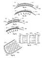
- FIGS. 1 a - cshow schematic cross-section views of devices according to embodiments of the invention
- FIGS. 1 d - eshow schematic cross-section views of devices according to the prior-art solutions
- FIG. 2shows a perspective view of a device according to a first embodiment of the invention
- FIG. 3shows a side view of a device according to a second embodiment of the invention
- FIGS. 4 a - bshow schematic cross-section views of a first embodiment of a proposed pressure transition system
- FIGS. 5 a - bshow schematic cross-section views of a second embodiment of a proposed pressure transition system
- FIGS. 6 a - cshow perspective views of further embodiments of the proposed pressure transition system
- FIG. 7shows a cross-section view of the pressure transition system according to a particular embodiment of the invention.
- FIGS. 8 a - billustrate a basic morphology of a planar field activated EAM-based actuator according to one embodiment of the invention
- FIGS. 9 a - cillustrate the morphology of a cylindrical field activated EAM-based actuator according to one embodiment of the invention
- FIGS. 10 a - billustrate the morphology of a field activated EAM-based actuator of multilayer type according to one embodiment of the invention
- FIGS. 11 a - billustrate the morphology of a field activated EAM-based actuator of C-block type according to one embodiment of the invention
- FIGS. 12 a - billustrate the morphology of a field activated EAM-based actuator of bubble type according to one embodiment of the invention
- FIG. 13shows a field activated EAM-based actuator of a first cymbal type according to one embodiment of the invention
- FIGS. 14 a - bshow a field activated EAM-based actuator of a second cymbal type having a flexible interface to link mechanical energy produced the actuator towards a body part according to one embodiment of the invention
- FIGS. 15 a - billustrate a basic morphology of an ionic EAM-based actuator according to one embodiment of the invention
- FIGS. 16 a - billustrate the morphology of a bilayer ionic EAM-based actuator according to one embodiment of the invention
- FIGS. 17 a - billustrate the morphology of a triple ionic layer EAM-based actuator according to one embodiment of the invention
- FIGS. 18 a - cshow side and top views of a conducting polymer actuator according to one embodiment of the invention
- FIGS. 19 a - bschematically illustrate the operation of a segment in a device according to one embodiment of the invention which includes actuators of the type shown in the FIGS. 18 a - c,
- FIGS. 20 a - bshow side views of a bending actuator according to one embodiment of the invention
- FIGS. 21 a - bschematically illustrate the operation of a segment in a device according to one embodiment of the invention which includes actuators of the type shown in the FIGS. 16 a - b,
- FIG. 22schematically illustrates a devices according to one embodiment of the invention.
- FIGS. 23-26illustrate examples of therapeutic garments including the proposed device.
- FIG. 1 ashows schematic cross-section view of a device according to one embodiment of the invention for exerting an external pressure to a human body part 100 .
- the deviceincludes a segment S 1 , which is adapted to at least partially enclose the body part 100 in a form-fitting manner.
- the segment S 1contains a controllable active-material based actuator A 1 (e.g. of electroactive ceramics or polymer, conducting-polymer, carbon-nanotube or electroactive-gel type) that in response to a control signal is adapted to cause the segment S 1 to apply a basic pressure profile P 1 to the body part 100 .
- a 1e.g. of electroactive ceramics or polymer, conducting-polymer, carbon-nanotube or electroactive-gel type
- a pressure transition system PTS of the deviceis adapted to redistribute this basic pressure profile P 1 into an adjusted pressure profile P 1 ad , which is different from the basic pressure profile P 1 .
- the adjusted pressure profile P 1 adjis applied to the body part 100 .
- the pressure transition system PTSis an underlayer that is located between the segment S 1 and the body part 100 .
- the pressure transition system PTSmay include an auxetic-foam composite or alternative deformable microcellular structure, and have one or more walls of a stretchy fabric, which allow the system PTS to expand in the circumferential and/or axial directions, so that the external basic pressure profile P 1 causes a deformation of the system PTS, and as a result an adjusted pressure profile P 1 adj is exerted on the body part 100 .
- the pressure transition system PTSmay also include drug containing pockets (here generally illustrated by means of white circles).
- the system PTSis also adapted to administer a transport of any drug substance in these pockets to the body part 100 , for instance in connection with an applied basic pressure profile P 1 .
- the drug substancemay contain various topical agents for slow release application to the body part 100 . Such topical agents may soften or moisturize the tissues in the body part 100 to prevent cracking and maintain or improve the overall health of the patient's skin.
- the drug substancemay contain benzopyrones, flavonoids, coumarin, terpenses etc. for slow release into the underlying body part 100 .
- the drug substancemay be an antibacterial agent, which helps in preventing infection of a wound site in the body part 100 .
- the drug substanceis a gel, which is adapted to perform a thermotherapy on the body part 100 (e.g. a cryotherapy for pain relief, or a heat therapy to promote tissue healing).
- a thermotherapye.g. a cryotherapy for pain relief, or a heat therapy to promote tissue healing.
- the actuator A 1is based on an active material that requires an electrolyte and if a thermotherapy of the body part 100 is desired, it is preferable to let a gel based electrolyte play dual rolls in both operating the actuator A 1 and accomplishing the cryotherapy.
- FIG. 1 bshows a schematic cross-section view of a device according to one embodiment of the invention where the device includes (at least) two segments S 1 and S 2 .
- a first segment S 1at least partially encloses a first portion B 1 of a body part 100 and a second segment S 2 at least partially encloses a second portion B 2 of the body part 100 .
- the pressure transition system PTSis here adapted to redistribute pressure profiles between the first and second segments S 1 and S 2 .
- the second segment S 2receives a control signal which causes this segment S 2 to generate a second basic pressure profile P 2 , the pressure transition system PTS applies a second adjusted pressure profile P 2 adj to at least a part of the first portion B 1 of the body part 100 .
- pressure profilesare applied to the body part 100 in response to control signals in respect of the segments S 1 and S 2 relatively smoothed-out, or fuzzy. This is advantageous both from a medical and a patient-comfort point-of-view.
- the pressure transition system PTSis adapted to apply a bias pressure profile to the body part, such that the body part 100 is exerted to an initial pressure profile also before any of the basic pressure profiles P 1 or P 2 are applied.
- the bias pressure profilemay be attained passively due to the pressure transition system PTS being stretchy. Then, the segments S 1 and S 2 may operate “on top of” this bias pressure profile to provide adjustments and/or dynamic therapies.
- the pressure transition system PTSnot only redistributes the basic pressure profiles P 1 or P 2 but also modifies the magnitude of the average pressure.
- the segments S 1 and S 2may apply basic pressure profiles P 1 and P 2 of 20 mmHg to the pressure transition system PTS, which already applies 20 mmHg to the body part 100 .
- a pressure in the order of 40 mmHgis applied to the body part 100 .
- the pressure transition system PTSis positioned between a first surface defined by the first and second segments S 1 and S 2 , and a second surface defined by the body part 100 . Additionally, the pressure transition system PTS extends over the first and second portions B 1 and B 2 of the body part 100 .
- FIG. 1 cshows a diagram wherein the horizontal axis indicates a position along the body part 100 and the vertical axis reflects a pressure towards the body part 100 .
- a dashed linerepresents a desired pressure P des to be applied to the body part 100 .
- the pressure transition system PTSa comparatively even pressure P approximately at the P des -level along the entire extension of the pressure transition system PTS (i.e. also between and outside the segments S 1 and S 2 ).
- FIGS. 1 d and 1 eillustrate a situation corresponding to that shown in the FIGS. 1 b and 1 c , wherein the first and second segments S 1 and S 2 are form-fitted around the body part 100 , however without any intermediate pressure transition system PTS.
- unacceptable pressure peaks above the desired pressure P desoccur at several places, particularly at the edges of the segments S 1 and S 2 .
- the FIG. 1 ealso illustrates separate pressure curves P 1 and P 2 respectively, which are caused by each individual segment S 1 and S 2 in the absence of the pressure transition system PTS.
- FIG. 2shows a perspective view of a device according to a first embodiment of the invention.
- the pressure transition system PTSis at least positioned between the first and second segments S 1 and S 2 .
- the pressure transition system PTSmay bridge over pressure profiles and tension forces from one segment to another, i.e. from S 1 to S 2 , from S 2 to S 1 , etc.
- different degrees of coupling between the segmentsmay be attained depending upon which fiber directions that are chosen for a fabric used in the pressure transition system PTS.
- each segment S 1 and S 2includes an actuator A 1 and A 2 respectively.
- the segments S 1 and S 2include a respective strap member 240 and 250 , and the actuators A 1 and A 2 are located at one end of each segment.
- the actuators A 1 and A 2are further attached to the strap members 240 and 250 , which at least partially enclose the body part 100 .
- the actuators A 1 and A 2are adapted to pull the strap members 240 and 250 , thus accomplish tension forces relative to the body part 100 .
- many different forms of actuatorsmay produce such tension forces. For example bending, spring, wrinkle, bellows, laminates, friction drives, linear stack piezoceramic (or c-block) and knitted fiber actuators may be used.
- the actuators A 1 and A 2 of FIG. 2adjust their morphology so that a tangential movement T of segments S 1 and/or S 2 occurs. As a result, a radial pressure is exerted on the body part 100 .
- the actuators A 1 and A 2be adapted to maintain their adjusted morphologies also after that the control signals have ceased, i.e. that the control signals merely instigate the morphology change.
- the pressure transition system PTSis exclusively positioned between the segments S 1 and S 2 . This design is preferable if a very slim device profile is important. However, according to a second alternative embodiment of the invention, the pressure transition system PTS also extends underneath the segments S 1 and S 2 . In this case it is further preferable if the pressure transition system PTS has a low-friction surface towards the segments S 1 and S 2 , so that smooth tangential movements of the segments' strap members are enabled.
- the pressure transition system PTSmay include sensor elements 210 and 220 , which are adapted to register relevant parameters, and transmit data signals reflecting these parameters to a control unit for analysis.
- the sensor elements 210 and 220may be adapted to register pressure, and in this case the elements can take the form of thin film force sensors (e.g. capacitive, piezoresistive, piezoelectric, varying contact or Quantum Tunneling Composite—QTC). If, on the other hand, the sensor elements 210 and 220 are intended to monitor the local circumference of the body part 100 , the sensor element 230 may instead take the form of a resistive strip, an interdigitated electrode with contacts, or similar sensor which surrounds the body part 100 .
- the sensor elements 210 and 220may also be responsible for measuring physiological parameters, such as heart rate, galvanic skin response, electromyogram—EMG, blood oxygen levels, exudates extraction rates.
- physiological parameterssuch as heart rate, galvanic skin response, electromyogram—EMG, blood oxygen levels, exudates extraction rates.
- the pressure transition system PTSincludes a sensor element 230 that is adapted to register a parameter expressing an environmental condition in proximity to the body part 100 , e.g. temperature, airflow, humidity or contamination. Namely, these types of environmental conditions may also influence what is an ideal behavior of the proposed device. Thus, based on data signals from the sensor elements 210 and 220 and/or the sensor element 230 , a treatment profile executed by the device may be adjusted.
- FIG. 3shows a perspective view of a device according to a second embodiment of the invention.
- each of a number of segments S 1 , S 2 , etc.at least partially encloses a body part 100 .
- the segmentsare arranged such that a portion of one segment S 1 covers a portion of a neighboring segment S 2 , and so on.
- relatively smoothed-out, or fuzzy, pressure profilesmay be applied to the body part 100 in response to control signals in respect of the segments S 1 and S 2 .
- a pressure transition system PTSis located between the segments and the body part 100 .
- the pressure transition system PTShas a low-friction surface towards the segments S 1 and S 2 , so that smooth tangential movements of the segments S 1 and S 2 are allowed relative to the pressure transition system PTS.
- FIGS. 4 a - bshow two cross-section views of one embodiment of the proposed pressure transition system PTS.
- the pressure transition system PTSincludes a number of collapsible ribs 410 which are positioned between at least one segment S 1 and a particular portion of the body part 100 when the device is fitted on the body part 100 .
- a cover layer 420separates the ribs 410 from the body part 100 .
- the ribs 410extend along a general central axis of the body part 100 . Hence, in these cross-section views, we only see the section profile of the ribs 410 .
- an actuator A 1 of the segment S 1is adapted to cause a tangential movement T of the segment S 1 relative to the body part 100 (see FIG. 4 b ).
- the ribs 410are adapted to fold, such that when folded the ribs 410 exert a radial pressure P on the particular portion of the body part 100 .
- FIGS. 5 a - bshow two cross-section views of another embodiment of a proposed pressure transition system PTS.
- the pressure transition system PTSis adapted to trans-form a tangential movement T into a resulting radial pressure P on a body part 100 .
- the pressure transition system PTSincludes at least one flexible chamber 510 , which is positioned between at least one segment S 1 and the body part 100 when the device is fitted on the body part 100 .
- An actuator A 1 of the segment S 1is adapted to cause the tangential movement T of the segment S 1 relative to the body part 100 in response to a control signal.
- the tangential movement Tdeforms the flexible chamber 510 , so that the chamber 530 causes a radial pressure P on the body part 100 , preferably via an underlayer 520 .
- the chamber 510has at least one attachment point 530 to the segment S 1 . When the segment S 1 slides over the body part 100 the attachment point 530 follows this movement, and the chamber 510 is compressed.
- the chamber 510may contain any flexible medium, such as a gas, a gel or a liquid. In any case, chamber 510 has elastic walls, which according to a preferred embodiment of the invention are made of an anisotropic material.
- the chamber 510may be arranged relative to the body part 100 when the device is fitted thereto, such that the chamber 510 is relatively stretchable in a circumferential direction of the body part 100 and relatively stiff in a direction along a general central axis of the body part 100 .
- the radial pressure Pmay be well distributed over the body part 100 .
- the pressure transition system PTScan be soft in the circumferential direction, so that fit and patient comfort is enhanced.
- the tension-force to pressure transduction embodiments illustrated in the FIGS. 4 a - b and 5 a - bmay provide useful designs whenever a slim, robust and energy efficient device is desired.
- FIG. 6 ashows a perspective view of another embodiment of the proposed pressure transition system PTS, which includes a number of protrusions in the form of rigid ribs 620 .
- These ribs 620are adapted to be positioned between at least one segment S 1 , S 2 and S 3 respectively and a particular portion of the body part 100 .
- the ribs 620are adapted to extend along a general central axis of the body part 100 and to convert the basic pressure profile of the segments S 1 , S 2 and S 3 into a non-uniform pressure profile to the particular portion of the body part 100 .
- a peak pressure ridge of the non-uniform pressure profileis produced for each rib, and the pressure ridges are defined by the positioning of the ribs 620 relative to the body part 100 . More important, however, by means of the ribs 620 pressure profiles applied by the segments S 1 , S 2 and S 3 are distributed across the body part 100 .
- the ribs 620may be sewn into a soft backing material, so that the entire structure can easily expand in the radial direction (e.g. to accommodate a wide range of patient limb sizes) while being stiff in the axial direction (i.e. along the body part 100 ).
- the segments S 1 , S 2 and S 3have here been separated more than what is normally preferable.
- FIG. 6 bshows a perspective view of an alternative embodiment of the proposed pressure transition system PTS, where instead the protrusions are cylindrical bulges 630 .
- the bulges 630are adapted to be positioned between at least one segment S 1 and a particular portion of the body part when the device is fitted on the body part.
- the bulges 630are adapted to convert the basic pressure profile of the segment S 1 into a non-uniform pressure profile to the particular portion of the body part.
- each bulge 630causes a circular pressure peak. Such pressure peaks are particularly suitable when treating lymphoedema.
- FIG. 6 cshows yet another perspective view of a device according to one embodiment of the invention.
- the deviceincludes a number of segments S 1 , S 2 , . . . , Sn, which are arranged linearly along a body part 100 , such as an arm or a leg.
- a body part 100such as an arm or a leg.
- the segments S 1 , S 2 and S 3have also here been separated more than what is normally preferable.
- each segment S 1 , S 2 , . . . , Snis associated with a pressure transition system PTS which encloses the body part 100 and has fiber directions according to the curved lines.
- PTSpressure transition system
- the pressure transition systems PTSoverlap partially, such that some portions of the body part 100 are covered by more than one pressure transition system PTS. For instance, a majority of the body part 100 may be covered by at least two different pressure transition systems PTS.
- This configurationresults in that an activation of a first segment S 1 causes a pressure to be applied to portions of the body part 100 which may also be pressurized via a second segment S 2 , and so on.
- smoothed-out, or fuzzy, pressure profilesmay be applied to the body part 100 in response to control signals C(i) in respect of the segments S 1 , S 2 , . . . , Sn.
- a control unit 640produces a respective control signal C(i) to each of segment S 1 , S 2 , . . . , Sn.
- these control signals C(i)are distributed via a common signal delivery system 650 .
- the control unit 640is adapted to vary the control signals C(i) over time, so that a treatment profile is implemented with respect to the body part 100 .
- the treatment profilemay involve producing repeated cycles of variations between relatively high and relatively low basic pressure profiles by means of each segment S 1 , S 2 , . . . , Sn.
- the treatment profilemay be adaptive in response to a manipulation signal that either is an external signal, or is produced by the device itself.
- a manipulation signalthat either is an external signal, or is produced by the device itself.
- one or more sensor elements in the segments S 1 , S 2 , . . . , Snmay transmit data signals R to the control unit 640 . Consequently, the manipulation signal can be based on such data signals R, so that the treatment profile depends on a current state of the body part 100 and/or the current environmental conditions.
- the data signals Rmay reflect a patient's posture. Therefore, according to the invention, it is rendered possible to adapt the treatment profile to the posture. For example, if the segments S 1 , S 2 , . . .
- Snare fitted around the patient's leg, they may be completely relaxed when the patient is lying down (e.g. apply a pressure profile in the range 0-10 mmHg), apply a relatively low graduated pressure profile (e.g. in the range 0-40 mmHg) when the patient is standing up and apply a relatively high graduated pressure profile (e.g. in the range 0-60 mmHg) when the patient is sitting.
- control signals C(i)are electrical signals
- the segments S 1 , S 2 , . . . , Snhave actuators whose morphology is electrically adjustable.
- the adjustments of the actuator morphologiesare preferably only instigated by the control signals C(i) (i.e. no control signal is necessary to maintain an adjusted morphology).
- control unit 640may be connected to any of the proposed segments and pressure transition systems, i.e. not only the elements of embodiment shown in FIG. 6 c.
- FIG. 7shows a cross-section view of the pressure transition system PTS according to one embodiment of the invention, where the pressure transition system PTS includes a number of moisture passages 710 schematically illustrated as tubes with internal flanges. Each moisture passage 710 is adapted to receive exudates from the body part 100 , and thus assist in keeping the skin relatively dry.
- the pressure transition system PTSincludes one or more liquid receptacles 715 , and the moisture passages 710 are adapted to transport any received exudates from the body part 100 this/these receptacle/s 715 concomitantly with repeating cycles of a treatment profile executed by means of segments S 1 and S 2 associated with the pressure transition system PTS.
- the moisture passages 710 and liquid receptacles 715are accomplished by means of air pockets of an open-celled foam.
- the pressure transition system PTSincludes a number of air channels 720 which are adapted to allow air to pass to the body part 100 .
- the air channels 720may also be adapted to operate concomitantly with the repeating cycles of the treatment profile executed by means of the segments S 1 and S 2 , so that air is exchanged more efficiently between the body part 100 and a local environment outside thereof.
- open-celled foam openingsmay also constitute the air channels 720 .
- FIG. 8 aillustrates the basic morphology of a planar field activated EAM-based actuator 805 .
- Two essentially plate-shaped electrodes 810 and 811are here separated by means of an EAM piece 820 .
- an electric fieldis applied over the EAM piece 820 , i.e. when one of the electrodes 810 is connected to a first polarity, say a positive voltage, and the other electrode 820 is connected to a second polarity, say a negative voltage, the EAM piece 820 undergoes a shape change, for instance by becoming thinner and longer. This situation is shown in FIG. 1 b.
- the shape change of the EAM 820arises due to a variety of physical reasons when a non-zero charge is supplied to the electrodes 810 and 811 , for example via a power supply or a control signal. In response to such a charge, the EAM 820 attempts to undergo a change in shape.
- the magnitude of the shape changedepends on the material properties of the EAM 820 , the frequency of the charge application/removal and mechanical boundary conditions of the material.
- the change in shapeis related to the amount of charge accumulated on the surrounding electrodes 810 and 811 .
- a deformationi.e. a changed morphology
- the thus separated chargeswill slowly leak through the EAM. Therefore, in practice, some replenishment/maintenance charge is necessary to top up the existing charge, and maintain a desired deformation.
- FIGS. 9 a and 9 billustrate top- and side views respectively of the morphology of a cylindrical field activated EAM-based actuator 905 , which may be used to apply pressure according to the invention.
- a first cylindrical electrode 910is enclosed by an EAM piece 920 .
- a second electrode 911encloses the EAM piece 920 .
- FIG. 9 cshows a side-view corresponding to the FIG. 9 b , however where the first electrode 910 is connected to a positive voltage and the second electrode 911 is connected to a negative voltage.
- the EAM piece 920contracts in response to the applied electric field, and the actuator's 905 diameter decreases while its length increases.
- a multilayer cylindrical actuator of the type shown in the FIGS. 9 a and 9 bmay be accomplished straightforwardly by wrapping a planar actuator around a spring, or tube-like mandrel. Thereby, a compact, multilayered (i.e. high strength) tubular actuator can be cost effectively created from a simple planar starting geometry.
- FIG. 10 ashows a schematic side-view of a field activated EAM-based actuator 1005 of multilayer (or stacked) type, which may be used according to the present invention.
- Many interconnected layers of EAM 1020are here alternately separated by a first essentially planar electrode 1010 and a second essentially planar electrode 1011 .
- FIG. 10 billustrates the case when an electric field is applied across the electrodes 1010 and 1011 . As can be seen, this again results in a contraction of the EAM 1020 .
- a material expansionmay instead result if for example a piezoceramic is used as the EAM 1020 .
- a substantial mechanical amplificationcan be achieved.
- Triple layer actuatorscan be formed by means of two EAM pieces separated by a supporting element, where opposite electric fields are applied to the EAM pieces. Thereby, the actuator can be controlled to bend in two different directions depending on which EAM piece that is activated, or the polarities applied to each of the EAM pieces.
- layers of passive materialsmay also be laminated along with the active material. These extra layers are often useful when interfacing with the surroundings, improving adhesion between adjacent active material layers, and creating favorable residual stresses in the active material during manufacturing.
- FIG. 11 ashows a schematic side view of a field activated EAM-based actuator 1105 of C-block type, which also may be used according to the invention.
- a curved-profile laminate material 1130adjoins an EAM piece 1120 , which likewise has a curved profile.
- the general curved profile of each blockamplifies the motion of the basic movement of the EAM piece 1120 .
- Two or more of these blocksmay be connected in series with one another to accomplish a further amplification effect.
- the EAM piece 1120contracts according to what is illustrated in FIG. 11 b.
- FIG. 12 aillustrates the morphology of a field activated EAM-based actuator 1205 of bubble type according to one embodiment of the invention.
- an EAP membrane 1220shaped as a truncated sphere (or similar bubble-like shape), is attached to a rigid mounting material 1230 .
- a pneumatic pressure biasis used to create the convex shape of the EAP membrane 1220 .
- An electric field across the EAP membrane 1220causes the membrane 1220 to expand from its initial (inactivated) morphology.
- FIG. 12 billustrates such an activated state.
- such actuatorscan be used to create localized pressure points on the body.
- FIG. 13shows a field activated EAM-based actuator 1305 of cymbal type according to one embodiment of the invention.
- Multilayered EAM strips 1320are here located between two flexible, cymbal-shaped interface elements 630 .
- the strips 1320contract or expand and pull/push the interface elements 1330 inwards or outwards as indicated by the arrows.
- a pressurecan be applied via first and second contact surfaces 1335 a and 1335 b respectively, which are located at the distal ends of the interface elements 1330 .
- the interface elements 1330are flexible and the EAM strips 1320 are oriented with their longest sides parallel to a symmetry axis of the interface elements 1330 , i.e. according to a layered structure as illustrated in the FIG. 13 .
- FIG. 14 ashows a perspective view of another cymbal type of field activated EAM-based actuator 1405 , which may be used in a device according to the invention.
- FIG. 14 bshows a sectional side view of this actuator 1405 .
- two interface surfaces 1435 a and 1435 bare interconnected by means of a number of flexible members 1430 , which in turn, are attached to an EAM piece 1420 located between the interface surfaces 1435 a and 1435 b .
- the interface surfaces 1435 a and 1435 bmove toward one another D E (essentially along their symmetry axes).
- FIG. 15 aillustrates a basic morphology of an ionic EAM-based actuator 1505 according to one embodiment of the invention.
- Ionic electroactive materialsare characterized in that actuator systems based on them contain ions and that migration of these ions occurs under the influence of voltage potentials applied between electrodes 1510 and 1520 within the system. The ion migration, in turn, causes swelling or shrinking of the actuator.
- actuators based on ionic EAMscan also be used as various types of sensors and energy accumulators.
- conducting polymer actuatorsgenerally have an ion reservoir, such as an electrolyte 1550 (in the form of a liquid, a gel or a solid), which separates a working electrode 1510 and a counter electrode 1520 .
- the working electrode 1510usually includes the EAM (i.e. the conducting polymer).
- the counter electrode 1520may include an EAM, however usually different from the EAM of the working electrode 1510 .
- the counter electrode 1520may thus include a naturally conducting material, such as a metal or a graphite film.
- the counter electrode 1520may be made from nanocomposites, fabricated to have both high conductivity and low mechanical stiffness.
- the working electrode 1510may likewise include a composite of active materials and passive materials.
- the passive materialsare normally included to improve the conductive properties of the working electrode 1510 while not impeding movement of the electrode during operation.
- conductive nanocompositesrepresent a viable option for lamination with the conducting polymer material.
- a reference electrode 1530is present in the electrolyte 1550 to ensure that desired voltage potentials are maintained at appropriate levels at the other electrodes 1510 and 1520 during operation of the actuator 1505 .
- the electroactive polymercan undergo oxidation or reduction reactions. Large electric fields are generated at the interfaces between the electrodes 1510 and 1520 respectively and the electrolyte 1550 . This causes ion migration across the interfaces. Ions within the EAM can initiate conformational change of the crystallographic structures of the material, or they may take up interstitial spaces in the material and cause it to swell. If ions are extracted from the EAM in the working electrode 1510 due to migration, the working electrode 1510 may shrink.
- reactions at the electrode 1520may or may not result in another usable shape change in respect of this electrode.
- the details of the entire actuator system(such as the specific EAMs, electrolyte and counter electrode properties) together dictate the final response of the system during operation.
- FIG. 15 billustrates a situation where a positive voltage has been applied to the working electrode 1510 and a negative voltage has been applied to the counter electrode 1520 .
- the working electrode 1510extends while its width decreases.
- the working electrode 1510may be designed as a composite of conductive helical supporting structure encapsulated by the EAM (not shown here).
- a possible extension of the counter electrode 1520is illustrated by means of a dashed profile.
- FIG. 16 aillustrates the morphology of a bilayer ionic EAM-based actuator 1605 according to one embodiment of the invention.
- a working electrode 1610 of a conductive polymer (EAP)adjoins a non-conducting polymer backing element 1620 , which mainly functions as a mechanical support to the actuator laminate of the working electrode 1610 .
- a counter electrode 1611is arranged physically separated from both the working electrode 1610 and the backing element 1620 .
- the working electrode 1610 and the EAP 1620are attached to an anchor member 1630 , and all the elements 1610 , 1620 and 1611 are surrounded by an electrolyte 1640 .
- 16 bshows a situation when a negative voltage has been applied to the working electrode 1610 and a positive voltage has been applied to the counter electrode 1611 , causing the conductive polymer to contract, and as a result, the entire working electrode and backing element system to bend.
- FIG. 17 aillustrates the morphology of a triple ionic layer EAM-based actuator 1705 according to one embodiment of the invention, which is similar in morphology to the actuator design of FIGS. 16 a and 16 b .
- two conductive polymer electrodes 1710 and 1711are separated by means of a non-conducting polymer element 1720 .
- All the elements 1710 , 1711 and 1720are attached to an anchor member 1730 , and may or may not be surrounded by an electrolyte.
- the non-conducting polymer element 1720may include a solid polymer electrolyte, and thus forego the need for a surrounding electrolyte.
- FIG. 17 billustrates how the actuator 1705 upon activation can be controlled to flex in different directions ⁇ 1 and ⁇ 2 depending on the polarity of a voltage applied between the electrodes 1710 and 1711 .
- the actuator 1705bends upwards ⁇ 1 in response to a negative voltage potential connected to the first electrode 1710 and a positive voltage potential connected to the second electrode 1711 .
- the actuator 1705would bend downwards ⁇ 2 in response to opposite voltage potentials.
- the actuators according to the inventionmay take the form of fibers, fabrics or strips based on the basic concept ionic EAM-based actuators.
- the basic actuator morphologiesmay be combined and be arranged in arrays to produce more advanced actuators.
- FIG. 18 ashows a side view of an inactivated conducting polymer actuator A 1 according to one embodiment of the invention.
- FIG. 18 bshows a corresponding top view.
- This actuator A 1operates according to the basic principle described above with reference to the FIGS. 15 a and 15 b .
- both a working electrode 1810 and a counter electrode 1820include a conductive polymer.
- An electrolyte 1830is enclosed by these electrodes 1810 and 1820 .
- the actuator A 1is activated by means of an applied voltage between a first electrode tab 1810 a and a second electrode tab 1810 b .
- the working electrode 1810contracts and the counter electrode 1820 expands.
- the actuator A 1both contracts in plane and expands out of the plane according to the top-view illustration of FIG. 18 c.
- FIG. 19 aillustrates a side view of a segment in a device according to one embodiment of the invention, which includes a number of actuators A 1 1 , A 1 2 , and A 1 3 of the type shown in the FIGS. 18 a - c .
- one actuatoris sufficient to exert an external pressure to a body part 100 by means of the proposed device.
- a plurality of actuatorsmay be used. If so, the actuators are mechanically connected to one another to at least partially enclose the body part 100 , such as the limb of a patient, in a form-fitting manner.
- the devicemay be capable of completely disengaging the body part 100 at the conclusion of treatment.
- a strap 1910(or equivalent) transmits actuator forces around the body part 100 and fixates the actuators A 1 1 , A 1 2 and A 1 3 to the body part 100 .
- the strap 1910may contain a variety of locking mechanisms to assist with the removal of the device from the patient after treatment, or assist with size adjustment of the device to the patient.
- a first actuator A 1 1includes a first working electrode 1810 1 and a first counter electrode 1820 1 ;
- a second actuator A 1 2includes a second working electrode 1810 2 and a second counter electrode 1820 2 ; and
- a third actuator A 1 3includes a third working electrode 1810 3 and a third counter electrode 1820 3 .
- the first actuator A 1 1is connected to the second actuator A 1 2 , which in turn, is connected to the third actuator A 1 2 according to the configuration of FIG. 19 a .
- Strap members 1910are attached to the first and third actuator A 1 1 and A 1 3 to fixate the device to the body part 100 .
- each actuator A 1 1 , A 1 2 , and A 1 3are also electrically connected to an electric power source, so that the actuators can be activated by means of electric charges being supplied to their electrodes. However, for reasons of a clear presentation, this is not shown in the FIG. 19 a.
- a pressure transition system PTSis arranged as an interface between the actuators A 1 1 , A 1 2 and A 1 3 and the body part 100 .
- the pressure transition system PTSis adapted to re-distribute a basic pressure profile of the actuators A 1 1 , A 1 2 and A 1 3 , such that when the actuators are activated, an adjusted pressure profile different from the basic pressure profile is applied to the body part 100 .
- a smoother (or more fuzzy) pressure profile Pcan be applied to the body part, which is desirable in many medical applications.
- any voids between the actuators A 1 1 , A 1 2 and A 1 3 and the pressure transition system PTSare filled with an open-celled foam (not shown). Namely, this further assists in redistributing pressure from the actuators A 1 1 , A 1 2 and A 1 3 to the body part 100 without overly affecting the breath ability of the device.
- FIG. 19 billustrates a situation when all the actuators A 1 1 , A 1 2 and A 1 3 are activated, and therefore each actuator A 1 1 , A 1 2 and A 1 3 has adapted morphology equivalent to what is shown in the FIG. 18 c .
- a pressure profile Pis applied to the body part 100 , and as a further consequence the body part 100 is normally compressed/deformed (which is here illustrated by means of a reduced cross-section diameter). If, however, the body part 100 were very stiff, and therefore would not deform under the pressure profile P applied, the actuators A 1 1 , A 1 2 and A 1 3 and the strap members 1910 would exert tensile forces F around the body part 100 without undergoing the large deformations depicted in the FIG. 19 b.
- FIGS. 20 a and 20 bshow side views of a bending actuator A 2 according to one embodiment of the invention.
- this type of actuator A 2includes a bending member 2010 of field activated EAM-type.
- the bending member 2010is adapted to operate against a local pressure transition system PTS' and an over layer 2030 , for instance in the form of an appropriate interfacing fabric.
- An elastic back plate side of the bending member 2010faces the over layer 2030 .
- FIG. 20 aillustrates an inactivated state of the actuator A 2
- FIG. 20 billustrates an activated state.
- the bending member 2010pushes the over layer 2030 away from the local pressure transition system PTS'. This leads to tensile forces F in the over layer 2030 , which according to the invention may be converted into a desired pressure profile applied to a body part.
- FIG. 21 ashows a side view of a segment in a device according to one embodiment of the invention, which includes a number of actuators A 2 1 and A 2 2 of the type shown in the FIGS. 20 a and 20 b .
- the number of actuatorsis increased to accommodate a wider range of available motion, and to more evenly distribute pressure to a curved body part 100 .
- two or more actuatorsmay be applied in parallel, i.e. be stacked, such that the actuators a layered on top of one another.
- multilayered laminates within each actuator element of an actuator arraymay be thickened. Nevertheless, for illustrative purposes only two actuators A 2 1 and A 2 2 are shown here.
- the actuators A 2 1 and A 2 2are located next to one another and have a common over layer 2110 (compare with 2030 in the FIGS. 20 a and 20 b ).
- the over layer 2110has at least one attachment point 2120 between the actuators A 2 1 and A 2 2 .
- each actuator A 2 1 and A 2 2contributes maximally to the generation of a pressure towards the body part 100 .
- a pressure transition system PTSis preferably arranged as an interface between the actuators A 1 1 and A 1 2 respectively and the body part 100 .
- Such a pressure transition system PTSis adapted to redistribute a basic pressure profile of the actuators A 1 1 and A 1 2 , so that when the actuators are activated, an adjusted pressure profile different from the basic pressure profile is applied to the body part 100 .
- a smoother (or more fuzzy) pressure profile Pcan be applied to the body part, which is desirable in many medical applications.
- FIG. 21 bshows a situation when the actuators A 1 1 and A 1 2 are activated, and a pressure profile P is applied to the body part 100 . Normally, this leads to a compression/deformation of the body part 100 (which is here illustrated by means of a reduced cross-section diameter). If, however, the body part 100 were very stiff, and therefore would not deform under the pressure profile P applied, yet the over layer 2110 would still exert tensile forces F around the body part 100 .
- the outer layer 2110should be made of a rigid and strong fabric, so that it does not stretch appreciably during activation of the actuators A 2 1 and A 2 2 . Therefore, the outer layer 2110 is preferably a knitted anisotropic material, which includes fibers (e.g. of Kevlar) that are strong in the circumferential direction (i.e. around the body part 100 ), and relatively soft in the axial direction (i.e. along the body part 100 ). Moreover, the outer layer 2110 fabric preferably has an open weave to ensure that the breath ability of the device is not compromised.
- fiberse.g. of Kevlar
- FIG. 22shows a side view of a device according to one embodiment of the invention for exerting an external pressure to a human body part 100 .
- the deviceincludes segments S 1 , S 2 and S 3 , which are adapted to at least partially enclose the body part 100 in a form-fitting manner.
- Each segment S 1 , S 2 and S 3contains a controllable active-material based actuator A (e.g. of the type illustrated in the FIGS. 21 a and 21 b ) that is adapted to cause the segment to apply a pressure profile to the body part 100 in response to a control signal C(i).
- a controllable active-material based actuator Ae.g. of the type illustrated in the FIGS. 21 a and 21 b
- the devicemay also include a pressure transition system PSS, which is adapted to re-distribute a basic pressure profile produced by the segments S 1 , S 2 and S 3 into an adjusted pressure profile which is different from the basic pressure profile.
- the pressure transition system PSSaccomplished a relatively smoothed-out, or fuzzy, pressure profile to be applied to the body part 100 . This is advantageous both from a medical and a patient-comfort point-of-view.
- the pressure transition system PSSin turn, preferably includes an auxetic-foam composite or other material having a deformable microcellular structure.
- FIGS. 23-26illustrate examples of therapeutic garments 2300 , 2400 , 2500 and 2600 including the proposed device.
- FIG. 23shows a leg garment 2300 , where a plurality of segments S 1 , S 2 , . . . , Sn are adapted to enclose both the upper and the lower part of a patients leg.
- An extensive pressure transition system PTSis adapted to redistribute basic pressure profiles generated by the segments S 1 , S 2 , . . . , Sn, so that the entire leg is exerted to adjusted pressure profiles, for example also at joint portions of the leg that are not covered by any segments.
- FIG. 24shows an arm garment 2400 , where a plurality of segments S 1 , S 2 , . . . , Sn are adapted to enclose a patient's forearm and over arm. Also here an extensive pressure transition system PTS is adapted to redistribute basic pressure profiles generated by the segments S 1 , S 2 , . . . , Sn. Thereby, for instance, an elbow portion which for flexibility reasons is not covered by segments may be exerted to pressure. Additionally, the pressure transition system PTS is adapted to extend over the patient's hand in the form of a compression glove 2410 , so as to prevent lymphatic fluids from pooling in the hand.
- FIGS. 25 and 26show garments 2500 and 2600 for exerting external pressures to a patient's foot and hand respectively.
- a plurality of segments S 1 , S 2 , . . . , Snare adapted to enclose a said extremities, and a pressure transition system PTS is adapted to redistribute basic pressure profiles generated by the segments S 1 , S 2 , . . . , Sn.
- basic pressure profilesmay be smoothed out and also portions which are not covered by segments may be pressurized.
Landscapes
- Health & Medical Sciences (AREA)
- Life Sciences & Earth Sciences (AREA)
- Veterinary Medicine (AREA)
- Animal Behavior & Ethology (AREA)
- General Health & Medical Sciences (AREA)
- Public Health (AREA)
- Epidemiology (AREA)
- Pain & Pain Management (AREA)
- Physical Education & Sports Medicine (AREA)
- Rehabilitation Therapy (AREA)
- Vascular Medicine (AREA)
- Engineering & Computer Science (AREA)
- Heart & Thoracic Surgery (AREA)
- Biomedical Technology (AREA)
- Surgery (AREA)
- Molecular Biology (AREA)
- Nuclear Medicine, Radiotherapy & Molecular Imaging (AREA)
- Medical Informatics (AREA)
- Reproductive Health (AREA)
- Dermatology (AREA)
- Percussion Or Vibration Massage (AREA)
- Prostheses (AREA)
- Orthopedics, Nursing, And Contraception (AREA)
- Electrotherapy Devices (AREA)
- Invalid Beds And Related Equipment (AREA)
- Medicines Containing Material From Animals Or Micro-Organisms (AREA)
- Materials For Medical Uses (AREA)
Abstract
Description
Claims (1)
Applications Claiming Priority (7)
| Application Number | Priority Date | Filing Date | Title |
|---|---|---|---|
| EP04445107.8 | 2004-10-11 | ||
| EP04445108.6 | 2004-10-11 | ||
| EP04445108 | 2004-10-11 | ||
| EP04445108AEP1645255A1 (en) | 2004-10-11 | 2004-10-11 | Electro active compression bandage |
| EP04445107AEP1645254A1 (en) | 2004-10-11 | 2004-10-11 | Electro active compression bandage |
| EP04445107 | 2004-10-11 | ||
| PCT/EP2005/010886WO2006040109A1 (en) | 2004-10-11 | 2005-10-10 | Electro active compression bandage |
Related Parent Applications (1)
| Application Number | Title | Priority Date | Filing Date |
|---|---|---|---|
| PCT/EP2005/010886A-371-Of-InternationalWO2006040109A1 (en) | 2004-10-11 | 2005-10-10 | Electro active compression bandage |
Related Child Applications (1)
| Application Number | Title | Priority Date | Filing Date |
|---|---|---|---|
| US12/950,310DivisionUS8517963B2 (en) | 2004-10-11 | 2010-11-19 | Electro active compression bandage |
Publications (2)
| Publication Number | Publication Date |
|---|---|
| US20080195018A1 US20080195018A1 (en) | 2008-08-14 |
| US7857777B2true US7857777B2 (en) | 2010-12-28 |
Family
ID=35708532
Family Applications (4)
| Application Number | Title | Priority Date | Filing Date |
|---|---|---|---|
| US11/576,936Active2027-12-28US7857777B2 (en) | 2004-10-11 | 2005-10-10 | Electro active compression bandage |
| US12/950,310Expired - Fee RelatedUS8517963B2 (en) | 2004-10-11 | 2010-11-19 | Electro active compression bandage |
| US13/975,732AbandonedUS20130345610A1 (en) | 2004-10-11 | 2013-08-26 | Electro active compression bandage |
| US14/340,130Expired - LifetimeUS10071012B2 (en) | 2004-10-11 | 2014-07-24 | Electro active compression bandage |
Family Applications After (3)
| Application Number | Title | Priority Date | Filing Date |
|---|---|---|---|
| US12/950,310Expired - Fee RelatedUS8517963B2 (en) | 2004-10-11 | 2010-11-19 | Electro active compression bandage |
| US13/975,732AbandonedUS20130345610A1 (en) | 2004-10-11 | 2013-08-26 | Electro active compression bandage |
| US14/340,130Expired - LifetimeUS10071012B2 (en) | 2004-10-11 | 2014-07-24 | Electro active compression bandage |
Country Status (8)
| Country | Link |
|---|---|
| US (4) | US7857777B2 (en) |
| EP (1) | EP1814500B1 (en) |
| JP (1) | JP4728338B2 (en) |
| CN (1) | CN101039641B (en) |
| AT (1) | ATE397912T1 (en) |
| BR (1) | BRPI0516847A (en) |
| DE (1) | DE602005007513D1 (en) |
| WO (1) | WO2006040109A1 (en) |
Cited By (38)
| Publication number | Priority date | Publication date | Assignee | Title |
|---|---|---|---|---|
| US20090069902A1 (en)* | 2006-01-04 | 2009-03-12 | Nanopowers S.A. | Artificial contractile tissue |
| US20090234265A1 (en)* | 2008-03-13 | 2009-09-17 | Reid Jr Lawrence G | Compression Adjustable Fabric and Garments |
| US20100297334A1 (en)* | 2006-04-25 | 2010-11-25 | Boston Scientific Scimed, Inc. | Variable Stiffness Catheter Assembly |
| US20100305484A1 (en)* | 2007-12-06 | 2010-12-02 | Jean-Francois Grollier | Uses of electroactive material actuators in cosmetics |
| US20120193568A1 (en)* | 2009-01-16 | 2012-08-02 | Hon Hai Precision Industry Co., Ltd. | Electrostrictive composite and method for making the same |
| US8517963B2 (en) | 2004-10-11 | 2013-08-27 | Swelling Solutions, Inc. | Electro active compression bandage |
| US20140081187A1 (en)* | 2012-09-14 | 2014-03-20 | Recovery Force, LLC | Compression Integument |
| US8801643B2 (en) | 2010-02-12 | 2014-08-12 | Covidien Lp | Compression garment assembly |
| US20150065930A1 (en)* | 2012-09-14 | 2015-03-05 | Recovery Force, LLC | Compression Integument |
| US20150297442A1 (en)* | 2012-10-10 | 2015-10-22 | Fun Factory Gmbh | Massage device |
| WO2015161304A1 (en)* | 2014-04-17 | 2015-10-22 | Schroeder James E | Methods and apparatus for increasing the proximal movement of blood or lymph |
| US9248074B2 (en) | 2006-01-13 | 2016-02-02 | Swelling Solutions, Inc. | Device, system and method for compression treatment of a body part |
| US20160249698A1 (en)* | 2015-02-27 | 2016-09-01 | Omsignal Inc. | Apparatus, systems and methods for optimizing and masking compression in a biosensing garment |
| US9433532B2 (en) | 2008-09-30 | 2016-09-06 | Covidien Lp | Tubeless compression device |
| US9481777B2 (en) | 2012-03-30 | 2016-11-01 | The Procter & Gamble Company | Method of dewatering in a continuous high internal phase emulsion foam forming process |
| US20170128306A1 (en)* | 2014-06-23 | 2017-05-11 | Tacticle Systems Technology, Inc. | Compression garment system with tightening apparatus |
| US9936751B1 (en) | 2013-03-14 | 2018-04-10 | Francesco Mignone | Towel/absorptive arm sleeve and means of hands free toweling |
| US10076462B2 (en) | 2016-04-27 | 2018-09-18 | Radial Medical, Inc. | Adaptive compression therapy systems and methods |
| US10131993B2 (en) | 2015-01-16 | 2018-11-20 | Nanowear, Inc. | Large scale manufacturing of hybrid nanostructured textile sensors |
| US10231623B2 (en) | 2016-02-04 | 2019-03-19 | Nanowear Inc. | Roll-to-roll printing process for manufacturing a wireless nanosensor |
| USD848625S1 (en) | 2017-09-28 | 2019-05-14 | Tactile Systems Technology, Inc. | Leg garment |
| USD849254S1 (en) | 2017-09-28 | 2019-05-21 | Tactile Systems Technology, Inc. | Combination trunk and leg garment |
| US10441491B2 (en) | 2012-09-14 | 2019-10-15 | Recovery Force, LLC | Compression device |
| USD870297S1 (en) | 2017-09-28 | 2019-12-17 | Tactile Systems Technology, Inc. | Trunk garment |
| US10932720B2 (en) | 2011-03-08 | 2021-03-02 | Nanowear Inc. | Smart materials, dry textile sensors, and electronics integration in clothing, bed sheets, and pillow cases for neurological, cardiac and/or pulmonary monitoring |
| US10959634B2 (en) | 2017-05-02 | 2021-03-30 | Nanowear Inc. | Wearable congestive heart failure management system |
| US20210153748A1 (en)* | 2015-10-07 | 2021-05-27 | Fiomet Ventures, Inc. | Advanced Compression Garments and Systems |
| US11111593B2 (en) | 2015-01-16 | 2021-09-07 | Nanowear Inc. | Large scale manufacturing of hybrid nanostructured textile sensors |
| US11166868B2 (en) | 2015-10-05 | 2021-11-09 | Tactile Systems Technology, Inc. | Head and neck compression garment |
| US20220015933A1 (en)* | 2020-07-17 | 2022-01-20 | Toyota Motor Engineering & Manufacturing North America, Inc. | Appendage pressurization devices comprising artificial muscles |
| US11406561B2 (en) | 2014-02-11 | 2022-08-09 | Koya, Inc. | Compression garment apparatus |
| US11471368B2 (en) | 2020-06-10 | 2022-10-18 | Koya Medical, Inc. | Electro-actuatable compression garments with shape memory elements |
| US11583038B2 (en) | 2020-07-23 | 2023-02-21 | Koya Medical, Inc. | Quick connect anchoring buckle |
| US11648172B2 (en) | 2017-11-06 | 2023-05-16 | Tactile Systems Technology, Inc. | Compression garment systems |
| US11672729B2 (en) | 2014-02-11 | 2023-06-13 | Koya Medical, Inc. | Compression garment |
| US11707405B2 (en) | 2017-02-16 | 2023-07-25 | Koya Medical, Inc. | Compression garment |
| US11793680B2 (en) | 2020-03-12 | 2023-10-24 | Anne J. Lumsdaine | Compound (multi-layer) waterproof bandage |
| US11865059B2 (en) | 2012-09-14 | 2024-01-09 | Recovery Force, LLC | Compression device |
Families Citing this family (136)
| Publication number | Priority date | Publication date | Assignee | Title |
|---|---|---|---|---|
| US20170181921A1 (en)* | 2005-09-23 | 2017-06-29 | New Tec Pty Ltd | Therapeutic Device |
| US10208158B2 (en) | 2006-07-10 | 2019-02-19 | Medipacs, Inc. | Super elastic epoxy hydrogel |
| US7618384B2 (en) | 2006-09-20 | 2009-11-17 | Tyco Healthcare Group Lp | Compression device, system and method of use |
| KR100889752B1 (en)* | 2006-12-05 | 2009-03-24 | 한국전자통신연구원 | Hetero-junction membrane and method of producing the same |
| US9579483B2 (en)* | 2006-12-29 | 2017-02-28 | St. Jude Medical, Atrial Fibrillation Division, Inc. | Pressure-sensitive conductive composite contact sensor and method for contact sensing |
| CA2676207A1 (en) | 2007-01-24 | 2008-07-31 | Smm Medical Ab | An elastomeric particle having an electrically conducting surface, a pressure sensor comprising said particles, a method for producing said sensor and a sensor system comprising said sensors |
| US7655004B2 (en) | 2007-02-15 | 2010-02-02 | Ethicon Endo-Surgery, Inc. | Electroporation ablation apparatus, system, and method |
| WO2008146224A2 (en) | 2007-05-25 | 2008-12-04 | Compex Medical S.A. | Wound healing electrode set |
| US8579897B2 (en) | 2007-11-21 | 2013-11-12 | Ethicon Endo-Surgery, Inc. | Bipolar forceps |
| US8568410B2 (en) | 2007-08-31 | 2013-10-29 | Ethicon Endo-Surgery, Inc. | Electrical ablation surgical instruments |
| US8262655B2 (en) | 2007-11-21 | 2012-09-11 | Ethicon Endo-Surgery, Inc. | Bipolar forceps |
| US8480657B2 (en) | 2007-10-31 | 2013-07-09 | Ethicon Endo-Surgery, Inc. | Detachable distal overtube section and methods for forming a sealable opening in the wall of an organ |
| US20090112059A1 (en) | 2007-10-31 | 2009-04-30 | Nobis Rudolph H | Apparatus and methods for closing a gastrotomy |
| WO2009062167A1 (en) | 2007-11-09 | 2009-05-14 | Personics Holdings Inc. | Electroactive polymer systems |
| JP2011505520A (en) | 2007-12-03 | 2011-02-24 | メディパックス インコーポレイテッド | Fluid metering device |
| US20110054366A1 (en)* | 2008-02-19 | 2011-03-03 | Kent Smith | Therapeutic pressure system |
| US8262680B2 (en) | 2008-03-10 | 2012-09-11 | Ethicon Endo-Surgery, Inc. | Anastomotic device |
| US8771260B2 (en) | 2008-05-30 | 2014-07-08 | Ethicon Endo-Surgery, Inc. | Actuating and articulating surgical device |
| US8679003B2 (en) | 2008-05-30 | 2014-03-25 | Ethicon Endo-Surgery, Inc. | Surgical device and endoscope including same |
| US8906035B2 (en) | 2008-06-04 | 2014-12-09 | Ethicon Endo-Surgery, Inc. | Endoscopic drop off bag |
| US8403926B2 (en) | 2008-06-05 | 2013-03-26 | Ethicon Endo-Surgery, Inc. | Manually articulating devices |
| US8361112B2 (en) | 2008-06-27 | 2013-01-29 | Ethicon Endo-Surgery, Inc. | Surgical suture arrangement |
| US8888792B2 (en) | 2008-07-14 | 2014-11-18 | Ethicon Endo-Surgery, Inc. | Tissue apposition clip application devices and methods |
| US8262563B2 (en) | 2008-07-14 | 2012-09-11 | Ethicon Endo-Surgery, Inc. | Endoscopic translumenal articulatable steerable overtube |
| US8211125B2 (en) | 2008-08-15 | 2012-07-03 | Ethicon Endo-Surgery, Inc. | Sterile appliance delivery device for endoscopic procedures |
| US8529563B2 (en) | 2008-08-25 | 2013-09-10 | Ethicon Endo-Surgery, Inc. | Electrical ablation devices |
| US8241204B2 (en) | 2008-08-29 | 2012-08-14 | Ethicon Endo-Surgery, Inc. | Articulating end cap |
| US8480689B2 (en) | 2008-09-02 | 2013-07-09 | Ethicon Endo-Surgery, Inc. | Suturing device |
| US8409200B2 (en) | 2008-09-03 | 2013-04-02 | Ethicon Endo-Surgery, Inc. | Surgical grasping device |
| US8337394B2 (en) | 2008-10-01 | 2012-12-25 | Ethicon Endo-Surgery, Inc. | Overtube with expandable tip |
| US8157834B2 (en) | 2008-11-25 | 2012-04-17 | Ethicon Endo-Surgery, Inc. | Rotational coupling device for surgical instrument with flexible actuators |
| US8361066B2 (en) | 2009-01-12 | 2013-01-29 | Ethicon Endo-Surgery, Inc. | Electrical ablation devices |
| FR2940904B1 (en) | 2009-01-13 | 2012-08-31 | Urgo Laboratoires | INTERFACE PRESSURE MEASURING SYSTEM |
| US9226772B2 (en) | 2009-01-30 | 2016-01-05 | Ethicon Endo-Surgery, Inc. | Surgical device |
| US8252057B2 (en) | 2009-01-30 | 2012-08-28 | Ethicon Endo-Surgery, Inc. | Surgical access device |
| US20110152736A1 (en)* | 2009-05-19 | 2011-06-23 | Djo, Llc | Brace having a Force Indicator |
| WO2011032011A1 (en) | 2009-09-10 | 2011-03-17 | Medipacs, Inc. | Low profile actuator and improved method of caregiver controlled administration of therapeutics |
| US20110098704A1 (en) | 2009-10-28 | 2011-04-28 | Ethicon Endo-Surgery, Inc. | Electrical ablation devices |
| US8608652B2 (en) | 2009-11-05 | 2013-12-17 | Ethicon Endo-Surgery, Inc. | Vaginal entry surgical devices, kit, system, and method |
| US8353487B2 (en) | 2009-12-17 | 2013-01-15 | Ethicon Endo-Surgery, Inc. | User interface support devices for endoscopic surgical instruments |
| US8496574B2 (en) | 2009-12-17 | 2013-07-30 | Ethicon Endo-Surgery, Inc. | Selectively positionable camera for surgical guide tube assembly |
| US8506564B2 (en) | 2009-12-18 | 2013-08-13 | Ethicon Endo-Surgery, Inc. | Surgical instrument comprising an electrode |
| US9028483B2 (en) | 2009-12-18 | 2015-05-12 | Ethicon Endo-Surgery, Inc. | Surgical instrument comprising an electrode |
| US9005198B2 (en) | 2010-01-29 | 2015-04-14 | Ethicon Endo-Surgery, Inc. | Surgical instrument comprising an electrode |
| US9500186B2 (en) | 2010-02-01 | 2016-11-22 | Medipacs, Inc. | High surface area polymer actuator with gas mitigating components |
| KR101084782B1 (en)* | 2010-05-06 | 2011-11-21 | 삼성전기주식회사 | Touch screen device |
| WO2012078724A1 (en)* | 2010-12-08 | 2012-06-14 | Convatec Technologies Inc. | Apparatus and method for applying pressure to a wound site |
| US10092291B2 (en) | 2011-01-25 | 2018-10-09 | Ethicon Endo-Surgery, Inc. | Surgical instrument with selectively rigidizable features |
| US9233241B2 (en) | 2011-02-28 | 2016-01-12 | Ethicon Endo-Surgery, Inc. | Electrical ablation devices and methods |
| US9314620B2 (en) | 2011-02-28 | 2016-04-19 | Ethicon Endo-Surgery, Inc. | Electrical ablation devices and methods |
| US9254169B2 (en) | 2011-02-28 | 2016-02-09 | Ethicon Endo-Surgery, Inc. | Electrical ablation devices and methods |
| US20120232447A1 (en)* | 2011-03-07 | 2012-09-13 | Charles Gordon | Systems and methods for deep vein thrombosis prophylaxis |
| US9049987B2 (en) | 2011-03-17 | 2015-06-09 | Ethicon Endo-Surgery, Inc. | Hand held surgical device for manipulating an internal magnet assembly within a patient |
| US8986199B2 (en) | 2012-02-17 | 2015-03-24 | Ethicon Endo-Surgery, Inc. | Apparatus and methods for cleaning the lens of an endoscope |
| CN102579237B (en)* | 2012-03-08 | 2014-03-12 | 北京龙马负图科技有限公司 | Intermittent pneumatic compression system with venous refilling detecting function |
| US10000605B2 (en) | 2012-03-14 | 2018-06-19 | Medipacs, Inc. | Smart polymer materials with excess reactive molecules |
| US9427255B2 (en) | 2012-05-14 | 2016-08-30 | Ethicon Endo-Surgery, Inc. | Apparatus for introducing a steerable camera assembly into a patient |
| US20140012174A1 (en)* | 2012-07-03 | 2014-01-09 | Mao-Tsun Wu | Adhesive Bandage |
| US9078662B2 (en) | 2012-07-03 | 2015-07-14 | Ethicon Endo-Surgery, Inc. | Endoscopic cap electrode and method for using the same |
| US9545290B2 (en) | 2012-07-30 | 2017-01-17 | Ethicon Endo-Surgery, Inc. | Needle probe guide |
| US10314649B2 (en) | 2012-08-02 | 2019-06-11 | Ethicon Endo-Surgery, Inc. | Flexible expandable electrode and method of intraluminal delivery of pulsed power |
| US9572623B2 (en) | 2012-08-02 | 2017-02-21 | Ethicon Endo-Surgery, Inc. | Reusable electrode and disposable sheath |
| US9277957B2 (en) | 2012-08-15 | 2016-03-08 | Ethicon Endo-Surgery, Inc. | Electrosurgical devices and methods |
| US10098527B2 (en) | 2013-02-27 | 2018-10-16 | Ethidcon Endo-Surgery, Inc. | System for performing a minimally invasive surgical procedure |
| US20160074234A1 (en)* | 2013-04-16 | 2016-03-17 | Drexel University | Radial compression utilizing a shape-memory alloy |
| US9615992B2 (en)* | 2013-07-30 | 2017-04-11 | Lockheed Martin Corporation | System and method for supplementing circulation in a body |
| AU2014305656B2 (en)* | 2013-08-08 | 2018-11-08 | Clarus Technologies Pty Ltd | Bionic muscle |
| WO2015038598A1 (en)* | 2013-09-11 | 2015-03-19 | Massachusetts Institute Of Technology | Controllable compression garments using shape memory alloys and associated techniques and structures |
| US20150073319A1 (en)* | 2013-09-11 | 2015-03-12 | Massachusetts Institute Of Technology | Controllable Compression Textiles Using Shape Memory Alloys and Associated Products |
| US10058647B2 (en)* | 2013-10-04 | 2018-08-28 | President And Fellows Of Harvard College | Biomimetic actuation device and system, and methods for controlling a biomimetic actuation device and system |
| CN103584998B (en)* | 2013-11-13 | 2015-06-24 | 苏州市玖华服饰手套有限公司 | Conducting massage glove with silver fibers |
| DE102013224431B4 (en)* | 2013-11-28 | 2015-06-18 | 4A Engineering Gmbh | Setting aid for setting a catheter for diabetics |
| JP6425124B2 (en) | 2014-01-31 | 2018-11-21 | パナソニックIpマネジメント株式会社 | Massage device |
| US9962313B2 (en)* | 2014-02-11 | 2018-05-08 | Ronald G. Scott, Llc | Compression garment and method of forming the same |
| GB201403692D0 (en)* | 2014-03-03 | 2014-04-16 | Univ Tartu | Mechanotherapeutic device and measurment method |
| TWI556813B (en)* | 2014-03-11 | 2016-11-11 | 緯創資通股份有限公司 | Wearable device, electronic apparatus and method for recording user actions |
| US20150257968A1 (en)* | 2014-03-11 | 2015-09-17 | Carl E. VAUSE | Soft conformal compression devices and methods |
| JP2015186568A (en)* | 2014-03-13 | 2015-10-29 | パナソニックIpマネジメント株式会社 | Massage apparatus and massage method |
| AU2015244122B2 (en)* | 2014-04-07 | 2017-08-03 | The Penn State Research Foundation | Neonatal chest splint for applying negative distending pressure |
| KR102245098B1 (en) | 2014-05-23 | 2021-04-28 | 삼성전자주식회사 | Mobile terminal and control method thereof |
| US11638676B2 (en) | 2014-08-26 | 2023-05-02 | Ventrk, Llc | Garment system including at least one sensor and at least one actuator responsive to the sensor and related methods |
| US9687404B2 (en)* | 2014-08-26 | 2017-06-27 | Elwha Llc | Garment system including at least one muscle or joint activity sensor and at least one actuator responsive to the sensor and related methods |
| US10668305B2 (en) | 2014-08-26 | 2020-06-02 | Elwha Llc | Garment system including at least one therapeutic stimulation delivery device and related methods |
| US10456604B2 (en) | 2014-08-26 | 2019-10-29 | Elwha Llc | Garment system including at least one therapeutic stimulation delivery device and related methods |
| US10232165B2 (en) | 2015-01-29 | 2019-03-19 | Elwha Llc | Garment system including at least one sensor and at least one actuator responsive to the sensor and related methods |
| US20160058657A1 (en)* | 2014-08-29 | 2016-03-03 | Cornell University | Flexible wearable devices having embedded actuators providing motion stimulations |
| US20170246073A1 (en)* | 2014-09-18 | 2017-08-31 | Dajustco Ip Holdings Inc. | Piezoelectric compression stocking |
| EP3102269B1 (en) | 2014-10-02 | 2017-07-05 | Koninklijke Philips N.V. | Cushion element for a patient interface |
| EP3212066A4 (en)* | 2014-10-30 | 2018-07-04 | Elwha LLC | Garment system including at least one sensor and at least one actuator responsive to the sensor and related methods |
| US10603191B2 (en) | 2014-11-04 | 2020-03-31 | Ras Labs, Inc. | Electroactive polymers and systems using the same |
| WO2016077150A1 (en) | 2014-11-14 | 2016-05-19 | Massachusetts Institute Of Technology | Wearable, self-locking shape memory alloy (sma) actuator cartridge |
| EP4284149A3 (en)* | 2014-12-29 | 2024-03-06 | Elastimed Ltd. | Methods and mechanisms for maintaining an electro-active polymer in a pre-stretch state and uses thereof |
| US20220241118A1 (en) | 2014-12-29 | 2022-08-04 | ElastiMed Ltd. | Methods and mechanisms for maintaining an electro-active polymer in a pre-stretch state and uses thereof |
| JP6766152B2 (en)* | 2014-12-29 | 2020-10-07 | エラスティメッド・リミテッドElastiMed Ltd. | Methods and Mechanisms for Maintaining Electroactive Polymers in Pre-Stretched State and Their Use |
| CN104605987A (en)* | 2015-03-02 | 2015-05-13 | 李秀荣 | Fracture massaging band, and use and control method thereof |
| CA3019907C (en)* | 2015-04-03 | 2023-01-17 | Pression Inc. | System and method for synchronizing external compression of a limb for increased blood flow |
| WO2016179245A1 (en) | 2015-05-04 | 2016-11-10 | The Florida State University Research Foundation, Inc. | Negative poisson ratio piezoresistive sensor and method of manufacture |
| CN104887371B (en)* | 2015-05-11 | 2017-03-01 | 上海应用技术学院 | Scoliosis orthosis support with replaceable distributed liner |
| CN104958177B (en)* | 2015-07-10 | 2017-04-05 | 京东方科技集团股份有限公司 | Muscle massage device |
| US20170056279A1 (en)* | 2015-08-25 | 2017-03-02 | Francis Jack Wright | Nerve suppression device |
| US10310481B2 (en) | 2015-10-07 | 2019-06-04 | International Business Machines Corporation | Dynamic position control for electronic components |
| US20180190142A1 (en)* | 2015-12-06 | 2018-07-05 | Jeffrey James Quail | Tourniquet Training Device |
| DK3402400T3 (en)* | 2016-01-13 | 2021-05-17 | Specialbandager Dk As | Device and method for providing a target for the circumference of a body part |
| EP3402401B1 (en) | 2016-01-13 | 2021-03-10 | Specialbandager.dk A/S | Method for determining efficiency of a compression bandaging |
| US10036674B2 (en)* | 2016-03-21 | 2018-07-31 | Honda Motor Co., Ltd. | Capacitance measuring device and capacitance measurement method for dielectric elastomer |
| TWI581838B (en)* | 2016-03-23 | 2017-05-11 | 國立清華大學 | Pad with sensor and protector thereof |
| US20170296423A1 (en)* | 2016-04-19 | 2017-10-19 | Timothy Smith | Piezoelectric pressure cuff |
| US10524976B2 (en)* | 2016-04-21 | 2020-01-07 | United States Of America As Represented By The Secretary Of The Air Force | Intelligent compression wrap |
| JP2019524394A (en)* | 2016-06-23 | 2019-09-05 | ラス・ラブズ・インコーポレイテッドRAS Labs, Inc. | Electroactive polymer that stretches, senses pressure, and reduces force and system using same |
| WO2018058234A1 (en)* | 2016-09-27 | 2018-04-05 | Bruce Murison | Devices exploiting hollow motors |
| US9889038B1 (en) | 2016-10-28 | 2018-02-13 | International Business Machines Corporation | Active adaptable compression structures |
| CA3051686A1 (en) | 2017-01-12 | 2018-07-19 | Shire Human Genetic Therapies, Inc. | Smart tourniquet |
| US20180242655A1 (en)* | 2017-02-24 | 2018-08-30 | Regents Of The University Of Minnesota | Smart fabric |
| US10481021B2 (en)* | 2017-05-25 | 2019-11-19 | TacSense, Inc. | Supercapacitive iontronic nanofabric sensing assemblies |
| US11259747B2 (en)* | 2017-06-30 | 2022-03-01 | James A. Magnasco | Adaptive compression sleeves and clothing articles |
| US11280031B2 (en) | 2017-07-14 | 2022-03-22 | Regents Of The University Of Minnesota | Active knit compression garments, devices and related methods |
| CA3071774A1 (en)* | 2017-08-01 | 2019-02-07 | ElastiMed Ltd. | Mechanisms for pre-stretching electro-active polymers by a pre-determined amount and methods of use thereof |
| EP4368156A3 (en) | 2017-11-09 | 2024-11-06 | ConvaTec Technologies Inc. | Ostomy monitoring system and method |
| EP3761940A4 (en)* | 2018-03-06 | 2021-11-24 | La Porta, Dallas | METHODS, DEVICES, AND SYSTEMS FOR APPLYING PRESSURE TO A NEWBORN |
| EP3787565B1 (en)* | 2018-05-02 | 2024-03-20 | Elastimed Ltd. | A strap having a portion of electro-active polymer, and methodsfor making and using the same |
| EP3824854B1 (en) | 2019-11-22 | 2024-08-21 | Neuraltide | Pressure application garment |
| WO2019232621A1 (en) | 2018-06-05 | 2019-12-12 | Bioastra Technologies Inc. | Stretchable solid-state electroactive polymer actuators |
| USD893514S1 (en) | 2018-11-08 | 2020-08-18 | 11 Health And Technologies Limited | Display screen or portion thereof with graphical user interface |
| CN109700102B (en)* | 2019-01-18 | 2020-08-18 | 安徽工程大学 | Adjustable pressurization clothes |
| CN109793291A (en)* | 2019-02-19 | 2019-05-24 | 京东方科技集团股份有限公司 | a garment |
| US20220416689A1 (en)* | 2019-10-21 | 2022-12-29 | ElastiMed Ltd. | Method of using a hydroelectric actuator to create a controllable pressure on a cylindrically shaped object |
| CN112315731B (en)* | 2019-11-20 | 2023-08-15 | 河南水滴智能技术有限公司 | Novel flexible exoskeleton material and control method |
| DE102020203208A1 (en)* | 2020-03-12 | 2021-09-16 | Fraunhofer-Gesellschaft zur Förderung der angewandten Forschung eingetragener Verein | Electromechanical converter and its use |
| US12115098B1 (en)* | 2020-05-14 | 2024-10-15 | Jason Fladoos | Physio tape with inductive heating system |
| US11986439B2 (en)* | 2020-05-26 | 2024-05-21 | Toyota Motor Engineering & Manufacturing North America, Inc. | Appendage massaging devices comprising artificial muscles |
| US11918539B2 (en) | 2020-06-10 | 2024-03-05 | Welch Allyn, Inc. | Wearable health management system |
| US20210393427A1 (en)* | 2020-06-19 | 2021-12-23 | Kinisi Inc | Wearable System for Evaluating Joint Performance and Function |
| US12343305B2 (en) | 2020-08-12 | 2025-07-01 | Welch Allyn, Inc. | Health management system |
| US12357494B2 (en) | 2020-10-15 | 2025-07-15 | Convatec Technologies Inc. | Ostomy systems and methods |
| CN112370107B (en)* | 2020-10-21 | 2022-07-01 | 天津大学 | An intelligent tourniquet device |
| USD1030237S1 (en) | 2022-06-10 | 2024-06-11 | Rhonda YOUNG | Garment |
Citations (19)
| Publication number | Priority date | Publication date | Assignee | Title |
|---|---|---|---|---|
| US3826249A (en) | 1973-01-30 | 1974-07-30 | A Lee | Leg constricting apparatus |
| SU1245312A1 (en) | 1984-11-11 | 1986-07-23 | Научно-Исследовательский Институт Трансплантологии И Искусственных Органов | Method of biological monitoring over development of fetus an egg |
| US5172689A (en)* | 1990-03-01 | 1992-12-22 | Wright Christopher A | Cryogenic sleeve for providing therapeutic compression |
| US5897517A (en)* | 1996-10-29 | 1999-04-27 | Alps South Corporation | Fabric reinforced elastomer materials |
| US5997465A (en) | 1994-03-17 | 1999-12-07 | Ffv Aerotech Ab | Device for exerting an external pressure on a human body |
| US6010471A (en) | 1996-04-15 | 2000-01-04 | Mego Afek Industrial Measuring Instruments | Body treatment apparatus |
| US6076013A (en)* | 1999-01-14 | 2000-06-13 | Brennan; Edward F. | Apparatus and methods for treating congestive heart failure |
| US6123681A (en) | 1998-03-31 | 2000-09-26 | Global Vascular Concepts, Inc. | Anti-embolism stocking device |
| US20020173735A1 (en) | 2000-12-08 | 2002-11-21 | Lewis Michael P. | External counterpulsation unit |
| US6506206B1 (en) | 1998-12-31 | 2003-01-14 | Depuy Orthopaedics, Inc. | Gel tourniquet cuff |
| EP1324406A2 (en) | 2001-12-26 | 2003-07-02 | Wilson Greatbatch Technologies, Inc. | SVO/CFx parallel cell design within the same casing |
| EP1324403A1 (en) | 2001-12-28 | 2003-07-02 | Matsushita Electric Works, Ltd. | Wearable human motion applicator |
| US6613350B1 (en)* | 1995-07-28 | 2003-09-02 | Zars, Inc. | Electrical apparatus for heating to a desired temperature for improved administration of pharmaceutically active compounds |
| US20030212306A1 (en) | 2002-05-10 | 2003-11-13 | Banik Michael S. | Electroactive polymer based artificial sphincters and artificial muscle patches |
| US7022093B2 (en)* | 2003-10-06 | 2006-04-04 | Thermodesigns, Inc. | Self-contained heating and cooling orthopaedic brace |
| US7044924B1 (en)* | 2000-06-02 | 2006-05-16 | Midtown Technology | Massage device |
| US7214847B1 (en)* | 1997-09-22 | 2007-05-08 | Argentum Medical, L.L.C. | Multilayer conductive appliance having wound healing and analgesic properties |
| US7491185B2 (en)* | 2003-08-21 | 2009-02-17 | Boston Scientific Scimed, Inc. | External counterpulsation device using electroactive polymer actuators |
| US20090299249A1 (en)* | 2008-05-30 | 2009-12-03 | Robert Peyton Wilkes | Reduced-pressure, compression systems and apparatuses for use on a curved body part |
Family Cites Families (177)
| Publication number | Priority date | Publication date | Assignee | Title |
|---|---|---|---|---|
| US4054540A (en) | 1973-02-26 | 1977-10-18 | Dynacon Industries, Inc. | Pressure sensitive resistance and process of making same |
| US4013069A (en) | 1975-10-28 | 1977-03-22 | The Kendall Company | Sequential intermittent compression device |
| US4030488A (en) | 1975-10-28 | 1977-06-21 | The Kendall Company | Intermittent compression device |
| US4029087A (en) | 1975-10-28 | 1977-06-14 | The Kendall Company | Extremity compression device |
| US4292261A (en) | 1976-06-30 | 1981-09-29 | Japan Synthetic Rubber Company Limited | Pressure sensitive conductor and method of manufacturing the same |
| US4091804A (en) | 1976-12-10 | 1978-05-30 | The Kendall Company | Compression sleeve |
| US4269175A (en) | 1977-06-06 | 1981-05-26 | Dillon Richard S | Promoting circulation of blood |
| US4207876A (en) | 1979-01-12 | 1980-06-17 | The Kendall Company | Compression device with ventilated sleeve |
| US4256094A (en) | 1979-06-18 | 1981-03-17 | Kapp John P | Arterial pressure control system |
| US4320746A (en) | 1979-12-07 | 1982-03-23 | The Kendall Company | Compression device with improved pressure control |
| US4396010A (en) | 1980-06-30 | 1983-08-02 | The Kendall Company | Sequential compression device |
| US4374518A (en) | 1980-10-09 | 1983-02-22 | Raul Villanueva | Electronic device for pneumomassage to reduce lymphedema |
| US4408599A (en) | 1981-08-03 | 1983-10-11 | Jobst Institute, Inc. | Apparatus for pneumatically controlling a dynamic pressure wave device |
| JPS5829462A (en)* | 1981-08-13 | 1983-02-21 | シャープ株式会社 | Massage device |
| IL63574A (en) | 1981-08-14 | 1985-07-31 | Mego Afek | Massaging sleeve for body limbs |
| US4402312A (en) | 1981-08-21 | 1983-09-06 | The Kendall Company | Compression device |
| FR2548017B1 (en) | 1983-06-16 | 1986-08-29 | Tissot Jean | IMPROVEMENTS ON PNEUMATIC MASSAGE DEVICES |
| GB8516957D0 (en) | 1985-07-04 | 1985-08-07 | Uniroyal Ltd | Pressure responsive materials |
| US5175214A (en) | 1985-11-11 | 1992-12-29 | Nitta Industries Corporation | Pressure-sensitive conductive elastomer compound |
| US5022387A (en) | 1987-09-08 | 1991-06-11 | The Kendall Company | Antiembolism stocking used in combination with an intermittent pneumatic compression device |
| US4858596A (en) | 1988-02-18 | 1989-08-22 | The Kendall Company | Portable sequential compression device |
| JPH01282802A (en) | 1988-05-09 | 1989-11-14 | Toshiba Silicone Co Ltd | Pressure-sensitive resistance element |
| DK159193C (en) | 1988-06-07 | 1991-03-25 | S O Siemssen | CONTRACTUAL AND COMPRESSION STRIPS CONSISTING OF MORE SUCH ITEMS FOR PERISTALTIC TREATMENT OF PATIENTS EXTREMITIES |
| US5108455A (en) | 1988-10-21 | 1992-04-28 | Telikicherla Madan M | Lower limb prosthesis having removable rigid amputation stump dressing |
| US5031604A (en) | 1989-04-12 | 1991-07-16 | The Kendall Company | Device for applying compressive pressures to a patient's limb |
| US5007411A (en) | 1989-04-12 | 1991-04-16 | The Kendall Company | Device for applying compressive pressures against a patient's limb |
| US5014681A (en) | 1989-05-05 | 1991-05-14 | Mego Afek Industrial Measuring Instruments | Method and apparatus for applying intermittent compression to a body part |
| US5052377A (en) | 1989-06-01 | 1991-10-01 | Jean Frajdenrajch | Apparatus for massaging the body by cyclic pressure, and constituent means |
| US5113887A (en) | 1989-07-27 | 1992-05-19 | Herman Jr Harry H | Mobility assisting devices |
| US5193549A (en) | 1990-07-11 | 1993-03-16 | Biomedical Dynamics Corporation | Inflatable cuff |
| JPH04121076A (en) | 1990-09-12 | 1992-04-22 | Canon Inc | vibration wave motor |
| US5117812A (en) | 1990-11-05 | 1992-06-02 | The Kendall Company | Segmented compression device for the limb |
| US5263473A (en) | 1990-11-05 | 1993-11-23 | The Kendall Company | Compression device for the limb |
| DE4119955C2 (en) | 1991-06-18 | 2000-05-31 | Danfoss As | Miniature actuator |
| US5186163A (en) | 1991-11-25 | 1993-02-16 | The Kendall Company | Compression device |
| US5302936A (en) | 1992-09-02 | 1994-04-12 | Interlink Electronics, Inc. | Conductive particulate force transducer |
| US5431064A (en) | 1992-09-18 | 1995-07-11 | Home Row, Inc. | Transducer array |
| US5324317A (en) | 1992-09-30 | 1994-06-28 | Medserve Group, Inc. | Interferential stimulator for applying low frequency alternating current to the body |
| SE510158C2 (en)* | 1992-10-29 | 1999-04-26 | Medevelop Ab | Anchorage elements for supporting prostheses and the use of such anchorage elements for fixing dentures |
| US5596241A (en) | 1993-01-18 | 1997-01-21 | Canon Kabushiki Kaisha | Vibration wave driven linear-motor or printer |
| US5372575A (en) | 1993-02-16 | 1994-12-13 | Safeguard Industrial Corporation | Therapeutic forearm appliance having pressure pad containing parallel chambers |
| US5443440A (en) | 1993-06-11 | 1995-08-22 | Ndm Acquisition Corp. | Medical pumping apparatus |
| IL106296A0 (en) | 1993-07-09 | 1993-12-28 | Nanomotion Ltd | Ceramic motor |
| US5453081A (en) | 1993-07-12 | 1995-09-26 | Hansen; Craig N. | Pulsator |
| US5383894A (en) | 1993-07-30 | 1995-01-24 | The Kendall Co. | Compression device having stepper motor controlled valves |
| US5795312A (en) | 1993-09-27 | 1998-08-18 | The Kendall Company | Compression sleeve |
| US5374283A (en) | 1993-12-01 | 1994-12-20 | Flick; A. Bart | Electrical therapeutic apparatus |
| US5437610A (en) | 1994-01-10 | 1995-08-01 | Spinal Cord Society | Extremity pump apparatus |
| US5370133A (en) | 1994-02-22 | 1994-12-06 | Darco International, Inc. | Lower leg, ankle and foot immobilization brace with uniform, adjustable compression |
| US5575762A (en) | 1994-04-05 | 1996-11-19 | Beiersdorf-Jobst, Inc. | Gradient sequential compression system and method for reducing the occurrence of deep vein thrombosis |
| US6786879B1 (en) | 1994-04-05 | 2004-09-07 | Kci Licensing, Inc. | Gradient sequential compression system for preventing deep vein thrombosis |
| US5591200A (en) | 1994-06-17 | 1997-01-07 | World, Inc. | Method and apparatus for applying pressure to a body limb for treating edema |
| CA2153375C (en) | 1994-07-26 | 2000-09-12 | Arnold Tobler | Attachment of hook and loop fastener to a compression sleeve |
| US5876359A (en) | 1994-11-14 | 1999-03-02 | Bock; Malcolm G. | Sequential compression device controller |
| DE69637293T2 (en) | 1995-02-17 | 2008-08-07 | Reid, Tony, Santa Cruz | DEVICE FOR TREATING OILS |
| US6656141B1 (en) | 1995-02-17 | 2003-12-02 | Tony Reid | Multiple sleeve method and apparatus for treating edema and other swelling disorders |
| US5759164A (en) | 1995-08-16 | 1998-06-02 | Pacey; John Allen | Apparatus and method for treating edema |
| US5643331A (en) | 1995-11-21 | 1997-07-01 | Katz; Amiram | Method and device for prevention of deep vein thrombosis |
| US5843007A (en) | 1996-04-29 | 1998-12-01 | Mcewen; James Allen | Apparatus and method for periodically applying a pressure waveform to a limb |
| US5906206A (en) | 1996-06-04 | 1999-05-25 | Circaio Medical Products, Inc. | Therapeutic compression garment |
| US5653244A (en) | 1996-06-04 | 1997-08-05 | Circaid Medical Products, Inc. | Therapeutic compression garment |
| US5918602A (en) | 1996-06-04 | 1999-07-06 | Circaid Medical Products, Inc. | Therapeutic compression garment |
| US5904145A (en) | 1996-11-12 | 1999-05-18 | Reid; Tony R. | Method and means for treating limb swelling disorders and the like |
| AU5674898A (en) | 1997-01-25 | 1998-08-18 | David Lussey | Polymer composition |
| US6179796B1 (en) | 1997-04-11 | 2001-01-30 | Tactile Systems, Inc. | Lymphedema treatment system |
| GB9712696D0 (en) | 1997-06-18 | 1997-08-20 | Smith & Nephew | Bandage |
| JPH119633A (en) | 1997-06-27 | 1999-01-19 | Tec Corp | Fluid massaging device |
| JPH1119145A (en) | 1997-07-01 | 1999-01-26 | Nitto Kohki Co Ltd | Compressed air distribution valve and distribution device |
| CA2210791A1 (en) | 1997-07-18 | 1999-01-18 | The University Of Manitoba | Diagnosis of edema |
| US5957867A (en) | 1997-10-28 | 1999-09-28 | Alere Incorporated | Method and device for detecting edema |
| US6494852B1 (en) | 1998-03-11 | 2002-12-17 | Medical Compression Systems (Dbn) Ltd. | Portable ambulant pneumatic compression system |
| US6041243A (en) | 1998-05-15 | 2000-03-21 | Northrop Grumman Corporation | Personal communications unit |
| US6002965A (en) | 1998-06-10 | 1999-12-14 | Katz; Amiram | Self applied device and method for prevention of deep vein thrombosis |
| US6007559A (en) | 1998-06-12 | 1999-12-28 | Aci Medical | Vascular assist methods and apparatus |
| JP4089082B2 (en) | 1998-07-28 | 2008-05-21 | 株式会社デンソー | Pressure sensitive conversion device |
| US6544202B2 (en) | 1998-08-12 | 2003-04-08 | Mcewen James Allen | Apparatus and method for applying an adaptable pressure waveform to a limb |
| US6062244A (en) | 1998-08-13 | 2000-05-16 | Aci Medical | Fluidic connector |
| US6338723B1 (en) | 1998-09-16 | 2002-01-15 | Circaid Medical Produts, Inc. | Compression device with compression measuring system |
| US6231532B1 (en) | 1998-10-05 | 2001-05-15 | Tyco International (Us) Inc. | Method to augment blood circulation in a limb |
| JP3909789B2 (en) | 1998-12-28 | 2007-04-25 | 日東工器株式会社 | Air massager |
| US6206510B1 (en) | 1999-04-22 | 2001-03-27 | Hewlett-Packard Company | Method and apparatus for adapting an ink jet printing system for receiving an alternate supply of ink |
| US6436064B1 (en) | 1999-04-30 | 2002-08-20 | Richard J. Kloecker | Compression garment for selective application for treatment of lymphedema and related illnesses manifested at various locations of the body |
| US6315745B1 (en) | 1999-04-30 | 2001-11-13 | Richard J. Kloecker | Compression garment for selective application for treatment of lymphedema and related illnesses manifested at various locations of the body |
| CN1175800C (en) | 1999-05-14 | 2004-11-17 | 松下电工株式会社 | Massager |
| US6290662B1 (en) | 1999-05-28 | 2001-09-18 | John K. Morris | Portable, self-contained apparatus for deep vein thrombosis (DVT) prophylaxis |
| US6254554B1 (en) | 1999-09-10 | 2001-07-03 | Medassist-Op, Inc. | Compression sleeve for treating lymphedema |
| DE10001845C2 (en)* | 2000-01-18 | 2002-03-07 | Norbert Egger | Fitness device in the form of an item of clothing |
| US6198204B1 (en) | 2000-01-27 | 2001-03-06 | Michael D. Pottenger | Piezoelectrically controlled active wear |
| US6690101B2 (en) | 2000-03-23 | 2004-02-10 | Elliptec Resonant Actuator Ag | Vibratory motors and methods of making and using same |
| US7001384B2 (en) | 2000-06-07 | 2006-02-21 | Aircast Llc | Method and apparatus for facilitating the healing of bone fractures |
| US6463934B1 (en) | 2000-06-12 | 2002-10-15 | Aircast, Inc. | Method for providing enhanced blood circulation |
| JP3980300B2 (en) | 2000-09-07 | 2007-09-26 | 株式会社フジクラ | Membrane pressure sensitive resistor and pressure sensor |
| US7548015B2 (en) | 2000-11-02 | 2009-06-16 | Danfoss A/S | Multilayer composite and a method of making such |
| US6846295B1 (en) | 2000-11-20 | 2005-01-25 | Mego Afek Industrial Measuring Instruments | Compression sleeve |
| US6558338B1 (en) | 2000-11-20 | 2003-05-06 | Mego Afek Industrial Measuring Instruments | System for and method of applying pressure to human body |
| AU2002215713A1 (en) | 2000-12-04 | 2002-06-18 | Bernard Hoste | Composite material for counteracting edema |
| US6437485B1 (en) | 2000-12-20 | 2002-08-20 | Piezomotor Uppsala Ab | Double bimorph electromechanical element |
| US6632188B2 (en) | 2001-01-08 | 2003-10-14 | D2Rm Corp. | Foot massaging apparatus utilizing air inflated nodes and air inflated nodes combined with a fluid |
| CA2434507A1 (en) | 2001-01-12 | 2002-07-18 | Midtown Technology Ltd. | Inflatable massage garment |
| US6833483B2 (en) | 2001-01-16 | 2004-12-21 | The Governors Of The University Of Alberta | Process for production of alcohols |
| IL141824A (en) | 2001-03-05 | 2008-11-03 | Flowmedic Ltd | Portable device for the enhancement of the circulation and for the prevention of stasis related deep vein thrombosis (dvt) |
| JP3932815B2 (en) | 2001-03-09 | 2007-06-20 | 株式会社デンソー | Anomaly detection method for sensor network |
| US6488677B1 (en) | 2001-05-10 | 2002-12-03 | Thermal Technologies, Inc. | System for quantifying edema |
| JP3899369B2 (en) | 2001-05-16 | 2007-03-28 | 株式会社フジ医療器 | Massage machine |
| DE10154526B4 (en) | 2001-06-12 | 2007-02-08 | Physik Instrumente (Pi) Gmbh & Co | Piezoelectric actuator |
| US6436448B1 (en) | 2001-06-25 | 2002-08-20 | Sky Biohealth Solutions, Inc. | Method for the treatment of lymphedema using guaifenesin |
| JP2003062023A (en) | 2001-08-22 | 2003-03-04 | Noritz Corp | Device for massaging lower limb |
| US7214203B2 (en) | 2001-09-21 | 2007-05-08 | Sung-Oh Hwang | Cardiopulmonary resuscitation apparatus |
| EP1465574B1 (en) | 2001-12-11 | 2015-07-29 | Covidien AG | Improvements in and relating to calf compression devices |
| DE60224844T2 (en) | 2001-12-21 | 2009-01-08 | Danfoss A/S | DIELECTRIC ACTUATOR OR SENSOR STRUCTURE AND MANUFACTURING METHOD |
| IL160185A0 (en) | 2004-02-02 | 2004-07-25 | Flowmedic Israel Ltd | A portable device for the enhancement of circulation of blood and lymph flow in a limb |
| US20030176825A1 (en) | 2002-03-18 | 2003-09-18 | Ortech Innovative Orthopedic Devices, Ltd. | Adjustable, elastic fixation device |
| EP1525024A1 (en) | 2002-06-12 | 2005-04-27 | JOHNSON, James P. | Compression garment with electro-stimulation |
| GB0217996D0 (en) | 2002-08-02 | 2002-09-11 | Novamedix Distrib Ltd | An inflatable device for use in impulse therapy |
| AU2002951193A0 (en) | 2002-09-04 | 2002-09-19 | Northern Sydney Area Health Service | Movement faciliatation device |
| EP1540807B1 (en) | 2002-09-20 | 2013-01-09 | Danfoss A/S | Elastomer actuator and method of making the actuator |
| US7868221B2 (en) | 2003-02-24 | 2011-01-11 | Danfoss A/S | Electro active elastic compression bandage |
| US7257051B2 (en) | 2003-03-06 | 2007-08-14 | General Electric Company | Integrated interface electronics for reconfigurable sensor array |
| GB0307097D0 (en) | 2003-03-27 | 2003-04-30 | Bristol Myers Squibb Co | Compression device for the limb |
| US7641623B2 (en) | 2003-04-11 | 2010-01-05 | Hill-Rom Services, Inc. | System for compression therapy with patient support |
| IL164286A0 (en) | 2004-09-26 | 2005-12-18 | Benny Rousso | A portable device for the enhancement of blood circulation |
| US7080562B2 (en) | 2003-10-17 | 2006-07-25 | Qortek, Inc. | High-sensitivity pressure conduction sensor for localized pressures and stresses |
| EP1533678A1 (en) | 2003-11-24 | 2005-05-25 | Sony International (Europe) GmbH | Physical feedback channel for entertaining or gaming environments |
| US7637879B2 (en) | 2003-12-29 | 2009-12-29 | Medical Compression Systems, (Dbn) Ltd. | Method and apparatus for assisting vascular flow through external compression synchronized with venous phasic flow |
| US7354410B2 (en) | 2004-02-23 | 2008-04-08 | Tyco Healthcare Group Lp | Compression treatment system |
| US7871387B2 (en) | 2004-02-23 | 2011-01-18 | Tyco Healthcare Group Lp | Compression sleeve convertible in length |
| US7329232B2 (en) | 2004-02-27 | 2008-02-12 | Circaid Medical Products, Inc. | Limb encircling therapeutic compression device |
| TWM253369U (en) | 2004-03-04 | 2004-12-21 | Chia Jei Technology Business C | Miniature self-administrative-type device for prevention of vein thrombosis |
| US8663144B2 (en) | 2004-03-22 | 2014-03-04 | Farrow Medical Innovations Holdings Llc | Modular compression device and method of assembly |
| US7942838B2 (en) | 2004-03-22 | 2011-05-17 | Farrow Medical Innovations, Inc. | Compression garment |
| US20080255494A1 (en) | 2004-06-06 | 2008-10-16 | Flowmedic Limited | Sleeves for Accommodating a Circulation Enhancement Device |
| US8079969B2 (en) | 2004-06-09 | 2011-12-20 | Benny Rousso | Portable self-contained device for enhancing circulation |
| IL164285A0 (en) | 2004-09-26 | 2005-12-18 | Benny Rousso | A portable device for the enhancent of blood |
| IL164360A0 (en) | 2004-09-29 | 2005-12-18 | Benny Rousso | A device for providing intermittent compression toa limb |
| US7857777B2 (en) | 2004-10-11 | 2010-12-28 | Convatec Technologies Inc. | Electro active compression bandage |
| EP1645254A1 (en) | 2004-10-11 | 2006-04-12 | SMM Medical AB | Electro active compression bandage |
| EP1833450B1 (en) | 2005-01-04 | 2018-02-14 | CARKNER, Steve | An automated massage therapy device for biomechanical rehabilitation massage and method for use |
| US7327637B2 (en) | 2005-02-23 | 2008-02-05 | Massachusetts Institute Of Technology | Acoustic pulse actuator |
| JP2006305293A (en) | 2005-03-31 | 2006-11-09 | Nitto Kohki Co Ltd | Pneumatic body action device |
| US8235921B2 (en) | 2005-05-01 | 2012-08-07 | Flow Medic Limited | Computerized portable device for the enhancement of circulation |
| FR2886784B1 (en) | 2005-06-01 | 2007-08-10 | Sagem Defense Securite | IMPROVEMENT TO CYLINDER MATERIALS OF ACTIVE PISTON ACTUATORS |
| US20060287672A1 (en) | 2005-06-15 | 2006-12-21 | Western Clinical Engineering Ltd. | Tourniquet cuff with improved pneumatic passageway |
| US7559358B2 (en) | 2005-08-03 | 2009-07-14 | Baker Hughes Incorporated | Downhole uses of electroactive polymers |
| US7442175B2 (en) | 2005-12-12 | 2008-10-28 | Tyco Healthcare Group Lp | Compression sleeve having air conduit |
| US8029451B2 (en) | 2005-12-12 | 2011-10-04 | Tyco Healthcare Group Lp | Compression sleeve having air conduits |
| US8083644B2 (en) | 2005-12-14 | 2011-12-27 | Peter Purdy | Resistance garments and active materials |
| CN101404968B (en) | 2006-01-13 | 2012-04-18 | 康沃特克科技公司 | Devices, systems and methods for compression treatment of body parts |
| US7618384B2 (en) | 2006-09-20 | 2009-11-17 | Tyco Healthcare Group Lp | Compression device, system and method of use |
| US7880371B2 (en) | 2006-11-03 | 2011-02-01 | Danfoss A/S | Dielectric composite and a method of manufacturing a dielectric composite |
| US7732999B2 (en) | 2006-11-03 | 2010-06-08 | Danfoss A/S | Direct acting capacitive transducer |
| GB0622415D0 (en) | 2006-11-10 | 2006-12-20 | Huntleigh Technology Plc | Compression system |
| US7976924B2 (en) | 2007-02-03 | 2011-07-12 | Raytheon Company | Active garment materials |
| US8182437B2 (en)* | 2007-05-08 | 2012-05-22 | Wright Therapy Products, Inc. | Pneumatic compression therapy system and methods of using same |
| EP2162109A4 (en) | 2007-06-20 | 2012-10-03 | Remo Moomiaie-Qajar | Portable compression device |
| PT2269540E (en) | 2007-07-04 | 2014-08-29 | Myopowers Medical Technologies Sa | Artificial contractile sphincter |
| US20090064476A1 (en) | 2007-07-27 | 2009-03-12 | The Penn State Research Foundation | Piezoelectric materials based on flexoelectric charge separation and their fabrication |
| JP2011505897A (en) | 2007-12-06 | 2011-03-03 | ロレアル | Use of electroactive material actuators in beauty |
| WO2009114676A1 (en) | 2008-03-13 | 2009-09-17 | Carolon Company | Compression adjustable fabric and garments |
| US8578939B1 (en) | 2008-04-07 | 2013-11-12 | Dreamscape Medical Llc | External pressure therapy apparatus |
| WO2010065644A2 (en) | 2008-12-02 | 2010-06-10 | Eddy Patrick E | Compression device and control system for applying pressure to a limb of a living being |
| US7992217B2 (en) | 2009-04-30 | 2011-08-09 | The Invention Science Fund I, Llc | Shape changing material |
| EP2440167B1 (en) | 2009-06-08 | 2016-05-25 | Farrow Innovations LLC | Customizable therapeutic compression garment and method |
| US8162869B2 (en) | 2009-07-10 | 2012-04-24 | Tyco Healthcare Group Lp | Hybrid compression garmet |
| WO2013033669A2 (en) | 2011-09-01 | 2013-03-07 | President And Fellows Of Harvard College | Actively controlled wearable orthotic devices and active modular elastomer sleeve for wearable orthotic devices |
| US20110040221A1 (en) | 2009-08-17 | 2011-02-17 | Kci Licensing, Inc. | System and Method to Reduce Stasis-Induced Reperfusion Injury |
| US8403870B2 (en) | 2009-09-15 | 2013-03-26 | Covidien Lp | Portable, self-contained compression device |
| US8394042B1 (en) | 2009-09-17 | 2013-03-12 | Mansoor Mirza | Portable sequential compression device |
| US8523794B2 (en) | 2009-09-17 | 2013-09-03 | Milka Llc | Method and apparatus for treating lymphedema |
| WO2011063213A1 (en) | 2009-11-20 | 2011-05-26 | Genz Ryan T | Fabric constructions with sensory transducers |
| CN102781482B (en) | 2009-11-24 | 2016-05-18 | 瑟克艾德医学产品有限公司 | Graduated Compression Device for Treatment of Circulatory Disorders |
| US20110131839A1 (en) | 2009-12-03 | 2011-06-09 | C-Boot Ltd. | Pneumatic Alternating Pressure Relief of a Foot |
| JP5733964B2 (en) | 2009-12-24 | 2015-06-10 | キヤノン株式会社 | Polymer actuator |
| US8257289B2 (en) | 2010-02-03 | 2012-09-04 | Tyco Healthcare Group Lp | Fitting of compression garment |
| US11000444B2 (en) | 2010-02-08 | 2021-05-11 | Gnotrix, Llc | Treatment devices and methods |
| DE102010021902B4 (en) | 2010-05-29 | 2014-04-17 | Faurecia Autositze Gmbh | Adjustment device for adjusting a vehicle seat element |
| WO2013025481A1 (en) | 2011-08-12 | 2013-02-21 | Avex, Llc | Foot compression and electrical stimulation system |
| NZ627780A (en) | 2012-03-12 | 2015-10-30 | Circaid Medical Products Inc | Adjustable elastic profile compression garment |
- 2005
- 2005-10-10USUS11/576,936patent/US7857777B2/enactiveActive
- 2005-10-10ATAT05802408Tpatent/ATE397912T1/ennot_activeIP Right Cessation
- 2005-10-10JPJP2007535113Apatent/JP4728338B2/ennot_activeExpired - Fee Related
- 2005-10-10EPEP05802408Apatent/EP1814500B1/ennot_activeExpired - Lifetime
- 2005-10-10CNCN2005800346691Apatent/CN101039641B/ennot_activeExpired - Fee Related
- 2005-10-10DEDE602005007513Tpatent/DE602005007513D1/ennot_activeExpired - Lifetime
- 2005-10-10BRBRPI0516847-3Apatent/BRPI0516847A/ennot_activeIP Right Cessation
- 2005-10-10WOPCT/EP2005/010886patent/WO2006040109A1/enactiveIP Right Grant
- 2010
- 2010-11-19USUS12/950,310patent/US8517963B2/ennot_activeExpired - Fee Related
- 2013
- 2013-08-26USUS13/975,732patent/US20130345610A1/ennot_activeAbandoned
- 2014
- 2014-07-24USUS14/340,130patent/US10071012B2/ennot_activeExpired - Lifetime
Patent Citations (19)
| Publication number | Priority date | Publication date | Assignee | Title |
|---|---|---|---|---|
| US3826249A (en) | 1973-01-30 | 1974-07-30 | A Lee | Leg constricting apparatus |
| SU1245312A1 (en) | 1984-11-11 | 1986-07-23 | Научно-Исследовательский Институт Трансплантологии И Искусственных Органов | Method of biological monitoring over development of fetus an egg |
| US5172689A (en)* | 1990-03-01 | 1992-12-22 | Wright Christopher A | Cryogenic sleeve for providing therapeutic compression |
| US5997465A (en) | 1994-03-17 | 1999-12-07 | Ffv Aerotech Ab | Device for exerting an external pressure on a human body |
| US6613350B1 (en)* | 1995-07-28 | 2003-09-02 | Zars, Inc. | Electrical apparatus for heating to a desired temperature for improved administration of pharmaceutically active compounds |
| US6010471A (en) | 1996-04-15 | 2000-01-04 | Mego Afek Industrial Measuring Instruments | Body treatment apparatus |
| US5897517A (en)* | 1996-10-29 | 1999-04-27 | Alps South Corporation | Fabric reinforced elastomer materials |
| US7214847B1 (en)* | 1997-09-22 | 2007-05-08 | Argentum Medical, L.L.C. | Multilayer conductive appliance having wound healing and analgesic properties |
| US6123681A (en) | 1998-03-31 | 2000-09-26 | Global Vascular Concepts, Inc. | Anti-embolism stocking device |
| US6506206B1 (en) | 1998-12-31 | 2003-01-14 | Depuy Orthopaedics, Inc. | Gel tourniquet cuff |
| US6076013A (en)* | 1999-01-14 | 2000-06-13 | Brennan; Edward F. | Apparatus and methods for treating congestive heart failure |
| US7044924B1 (en)* | 2000-06-02 | 2006-05-16 | Midtown Technology | Massage device |
| US20020173735A1 (en) | 2000-12-08 | 2002-11-21 | Lewis Michael P. | External counterpulsation unit |
| EP1324406A2 (en) | 2001-12-26 | 2003-07-02 | Wilson Greatbatch Technologies, Inc. | SVO/CFx parallel cell design within the same casing |
| EP1324403A1 (en) | 2001-12-28 | 2003-07-02 | Matsushita Electric Works, Ltd. | Wearable human motion applicator |
| US20030212306A1 (en) | 2002-05-10 | 2003-11-13 | Banik Michael S. | Electroactive polymer based artificial sphincters and artificial muscle patches |
| US7491185B2 (en)* | 2003-08-21 | 2009-02-17 | Boston Scientific Scimed, Inc. | External counterpulsation device using electroactive polymer actuators |
| US7022093B2 (en)* | 2003-10-06 | 2006-04-04 | Thermodesigns, Inc. | Self-contained heating and cooling orthopaedic brace |
| US20090299249A1 (en)* | 2008-05-30 | 2009-12-03 | Robert Peyton Wilkes | Reduced-pressure, compression systems and apparatuses for use on a curved body part |
Non-Patent Citations (3)
| Title |
|---|
| Applicant response to Written Opinion, dated May 2, 2006. |
| International Preliminary Report on Patentability for corresponding International Application No. PCT/EP2005/010886 completed Apr. 23, 2007. |
| International Search Report for PCT/EP2005/010886, completed on Feb. 7, 2006, mailed on Feb. 16, 2006. |
Cited By (64)
| Publication number | Priority date | Publication date | Assignee | Title |
|---|---|---|---|---|
| US8517963B2 (en) | 2004-10-11 | 2013-08-27 | Swelling Solutions, Inc. | Electro active compression bandage |
| US10071012B2 (en) | 2004-10-11 | 2018-09-11 | Swelling Solutions, Inc. | Electro active compression bandage |
| US20090069902A1 (en)* | 2006-01-04 | 2009-03-12 | Nanopowers S.A. | Artificial contractile tissue |
| US9248074B2 (en) | 2006-01-13 | 2016-02-02 | Swelling Solutions, Inc. | Device, system and method for compression treatment of a body part |
| US10828220B2 (en) | 2006-01-13 | 2020-11-10 | Tactile Systems Technology Inc. | Device, system and method for compression treatment of a body part |
| US20100297334A1 (en)* | 2006-04-25 | 2010-11-25 | Boston Scientific Scimed, Inc. | Variable Stiffness Catheter Assembly |
| US8920870B2 (en)* | 2006-04-25 | 2014-12-30 | Boston Scientific Scimed, Inc. | Variable stiffness catheter assembly |
| US20100305484A1 (en)* | 2007-12-06 | 2010-12-02 | Jean-Francois Grollier | Uses of electroactive material actuators in cosmetics |
| US20090234265A1 (en)* | 2008-03-13 | 2009-09-17 | Reid Jr Lawrence G | Compression Adjustable Fabric and Garments |
| US9433532B2 (en) | 2008-09-30 | 2016-09-06 | Covidien Lp | Tubeless compression device |
| US20120193568A1 (en)* | 2009-01-16 | 2012-08-02 | Hon Hai Precision Industry Co., Ltd. | Electrostrictive composite and method for making the same |
| US8253300B2 (en)* | 2009-01-16 | 2012-08-28 | Tsinghua University | Electrostrictive composite and method for making the same |
| US8801643B2 (en) | 2010-02-12 | 2014-08-12 | Covidien Lp | Compression garment assembly |
| US10932720B2 (en) | 2011-03-08 | 2021-03-02 | Nanowear Inc. | Smart materials, dry textile sensors, and electronics integration in clothing, bed sheets, and pillow cases for neurological, cardiac and/or pulmonary monitoring |
| US11399769B2 (en) | 2011-03-08 | 2022-08-02 | Nanowear Inc. | Smart materials, dry textile sensors, and electronics integration in clothing, bed sheets, and pillow cases for neurological, cardiac and/or pulmonary monitoring |
| US9481777B2 (en) | 2012-03-30 | 2016-11-01 | The Procter & Gamble Company | Method of dewatering in a continuous high internal phase emulsion foam forming process |
| US9809693B2 (en) | 2012-03-30 | 2017-11-07 | The Procter & Gamble Company | Method of dewatering in a continuous high internal phase emulsion foam forming process |
| US20150065930A1 (en)* | 2012-09-14 | 2015-03-05 | Recovery Force, LLC | Compression Integument |
| US10617593B2 (en)* | 2012-09-14 | 2020-04-14 | Recovery Force, LLC | Compression integument |
| US20140081187A1 (en)* | 2012-09-14 | 2014-03-20 | Recovery Force, LLC | Compression Integument |
| US11865059B2 (en) | 2012-09-14 | 2024-01-09 | Recovery Force, LLC | Compression device |
| US10441491B2 (en) | 2012-09-14 | 2019-10-15 | Recovery Force, LLC | Compression device |
| US9326911B2 (en)* | 2012-09-14 | 2016-05-03 | Recovery Force, LLC | Compression integument |
| US20150297442A1 (en)* | 2012-10-10 | 2015-10-22 | Fun Factory Gmbh | Massage device |
| US9936751B1 (en) | 2013-03-14 | 2018-04-10 | Francesco Mignone | Towel/absorptive arm sleeve and means of hands free toweling |
| US11903895B2 (en) | 2014-02-11 | 2024-02-20 | Koya Medical, Inc. | Compression garment apparatus |
| US11672729B2 (en) | 2014-02-11 | 2023-06-13 | Koya Medical, Inc. | Compression garment |
| US11406561B2 (en) | 2014-02-11 | 2022-08-09 | Koya, Inc. | Compression garment apparatus |
| US12383459B2 (en) | 2014-02-11 | 2025-08-12 | Koya Medical, Inc. | Compression garment apparatus |
| WO2015161304A1 (en)* | 2014-04-17 | 2015-10-22 | Schroeder James E | Methods and apparatus for increasing the proximal movement of blood or lymph |
| US20170128306A1 (en)* | 2014-06-23 | 2017-05-11 | Tacticle Systems Technology, Inc. | Compression garment system with tightening apparatus |
| US10492974B2 (en)* | 2014-06-23 | 2019-12-03 | Tactile Systems Technology, Inc. | Compression garment system with tightening apparatus |
| US11111593B2 (en) | 2015-01-16 | 2021-09-07 | Nanowear Inc. | Large scale manufacturing of hybrid nanostructured textile sensors |
| US10131993B2 (en) | 2015-01-16 | 2018-11-20 | Nanowear, Inc. | Large scale manufacturing of hybrid nanostructured textile sensors |
| US10660382B2 (en)* | 2015-02-27 | 2020-05-26 | Honeywell Safety Products Usa, Inc. | Apparatus, systems and methods for optimizing and masking compression in a biosensing garment |
| US11877614B2 (en) | 2015-02-27 | 2024-01-23 | Honeywell Safety Products Usa, Inc. | Apparatus, systems and methods for optimizing and masking compression in a biosensing garment |
| US20160249698A1 (en)* | 2015-02-27 | 2016-09-01 | Omsignal Inc. | Apparatus, systems and methods for optimizing and masking compression in a biosensing garment |
| US11376184B2 (en) | 2015-10-05 | 2022-07-05 | Tactile Systems Technology, Inc. | Static and dynamic compression therapy system |
| US11166868B2 (en) | 2015-10-05 | 2021-11-09 | Tactile Systems Technology, Inc. | Head and neck compression garment |
| US11311450B2 (en) | 2015-10-05 | 2022-04-26 | Tactile Systems Technology, Inc. | Head and neck compression therapy system |
| US20210153748A1 (en)* | 2015-10-07 | 2021-05-27 | Fiomet Ventures, Inc. | Advanced Compression Garments and Systems |
| US12036002B2 (en)* | 2015-10-07 | 2024-07-16 | Fiomet Ventures, Inc. | Advanced compression garments and systems |
| US10653316B2 (en) | 2016-02-04 | 2020-05-19 | Nanowear Inc. | Roll-to-roll manufacturing method of wireless nanosensor |
| US10231623B2 (en) | 2016-02-04 | 2019-03-19 | Nanowear Inc. | Roll-to-roll printing process for manufacturing a wireless nanosensor |
| US10076462B2 (en) | 2016-04-27 | 2018-09-18 | Radial Medical, Inc. | Adaptive compression therapy systems and methods |
| US10166164B2 (en) | 2016-04-27 | 2019-01-01 | Radial Medical, Inc. | Adaptive compression therapy systems and methods |
| US10736805B2 (en) | 2016-04-27 | 2020-08-11 | Radial Medical, Inc. | Adaptive compression therapy systems and methods |
| US11707405B2 (en) | 2017-02-16 | 2023-07-25 | Koya Medical, Inc. | Compression garment |
| US10959634B2 (en) | 2017-05-02 | 2021-03-30 | Nanowear Inc. | Wearable congestive heart failure management system |
| US12138058B2 (en) | 2017-05-02 | 2024-11-12 | Nanowear Inc. | Wearable congestive heart failure management system |
| USD870297S1 (en) | 2017-09-28 | 2019-12-17 | Tactile Systems Technology, Inc. | Trunk garment |
| USD1041014S1 (en) | 2017-09-28 | 2024-09-03 | Tactile Systems Technology, Inc. | Trunk garment |
| USD848625S1 (en) | 2017-09-28 | 2019-05-14 | Tactile Systems Technology, Inc. | Leg garment |
| USD849254S1 (en) | 2017-09-28 | 2019-05-21 | Tactile Systems Technology, Inc. | Combination trunk and leg garment |
| USD921207S1 (en) | 2017-09-28 | 2021-06-01 | Tactile Systems Technology, Inc. | Leg garment |
| US11648172B2 (en) | 2017-11-06 | 2023-05-16 | Tactile Systems Technology, Inc. | Compression garment systems |
| US12377013B2 (en) | 2017-11-06 | 2025-08-05 | Tactile Systems Technology, Inc. | Compression garment systems |
| US11793680B2 (en) | 2020-03-12 | 2023-10-24 | Anne J. Lumsdaine | Compound (multi-layer) waterproof bandage |
| US11471368B2 (en) | 2020-06-10 | 2022-10-18 | Koya Medical, Inc. | Electro-actuatable compression garments with shape memory elements |
| US11872152B2 (en)* | 2020-07-17 | 2024-01-16 | Toyota Motor Engineering & Manufacturing North America, Inc. | Appendage pressurization devices comprising artificial muscles |
| US20240099871A1 (en)* | 2020-07-17 | 2024-03-28 | Toyota Motor Engineering & Manufacturing North America, Inc. | Appendage pressurization devices comprising artificial muscles |
| US20220015933A1 (en)* | 2020-07-17 | 2022-01-20 | Toyota Motor Engineering & Manufacturing North America, Inc. | Appendage pressurization devices comprising artificial muscles |
| US11583038B2 (en) | 2020-07-23 | 2023-02-21 | Koya Medical, Inc. | Quick connect anchoring buckle |
| US12156571B2 (en) | 2020-07-23 | 2024-12-03 | Koya Medical, Inc. | Quick connect anchoring buckle |
Also Published As
| Publication number | Publication date |
|---|---|
| CN101039641B (en) | 2010-06-09 |
| BRPI0516847A (en) | 2008-09-23 |
| US20150025426A1 (en) | 2015-01-22 |
| JP4728338B2 (en) | 2011-07-20 |
| US20130345610A1 (en) | 2013-12-26 |
| US20080195018A1 (en) | 2008-08-14 |
| ATE397912T1 (en) | 2008-07-15 |
| JP2008515502A (en) | 2008-05-15 |
| CN101039641A (en) | 2007-09-19 |
| US10071012B2 (en) | 2018-09-11 |
| EP1814500B1 (en) | 2008-06-11 |
| EP1814500A1 (en) | 2007-08-08 |
| US8517963B2 (en) | 2013-08-27 |
| US20110066091A1 (en) | 2011-03-17 |
| WO2006040109A1 (en) | 2006-04-20 |
| DE602005007513D1 (en) | 2008-07-24 |
Similar Documents
| Publication | Publication Date | Title |
|---|---|---|
| US10071012B2 (en) | Electro active compression bandage | |
| US11369522B2 (en) | Pressure-sensing compression bandage | |
| US7868221B2 (en) | Electro active elastic compression bandage | |
| US12279987B2 (en) | Pad comprising a pressure element | |
| TW200950830A (en) | Reduced pressure, compression systems and apparatuses for use on joints | |
| Golgouneh et al. | A review in on-body compression using soft actuators and sensors: Applications, mechanisms, and challenges | |
| EP1645254A1 (en) | Electro active compression bandage | |
| EP1645255A1 (en) | Electro active compression bandage | |
| CN108697374B (en) | Apparatus and method for providing a measure of the circumference of a body part | |
| US20240099871A1 (en) | Appendage pressurization devices comprising artificial muscles | |
| JP5390043B1 (en) | Pneumatic articulation device | |
| Jiralerspong et al. | Soft Robotic Devices for Mechanotherapy of the Upper and Lower Extremities | |
| US20230380721A1 (en) | Pressure-Sensing Compression Bandage | |
| CN105813678B (en) | Cushion elements for patient interfaces | |
| CN218075665U (en) | eye massager | |
| CN112641612B (en) | Multistage adjustable active wearable lower limb rehabilitation device | |
| WO2022251339A1 (en) | Pressure differential therapeutic actuator | |
| US20220015932A1 (en) | Temporary cast devices comprising artificial muscles | |
| Bashkin et al. | Biomedical applications of dielectric elastomer actuators | |
| US20170296423A1 (en) | Piezoelectric pressure cuff | |
| CN215080871U (en) | Wearable lower limb rehabilitation device | |
| WO2023064291A1 (en) | Neck massaging systems and methods of using the same | |
| BR112022002159B1 (en) | CUSHION COMPRISING A PRESSURE ELEMENT AND ORTHOSIS OR BANDAGE | |
| CN117015360A (en) | Negative pressure therapy system with fixed locking tab | |
| Schreiber | Electroactive Polymers (EAPs) for Wearable Computing and Exoskeletons |
Legal Events
| Date | Code | Title | Description |
|---|---|---|---|
| AS | Assignment | Owner name:SMM MEDICAL AB, SWEDEN Free format text:ASSIGNMENT OF ASSIGNORS INTEREST;ASSIGNORS:LARSON, TOMAS;TOTH, LANDY;REEL/FRAME:019137/0993 Effective date:20070329 | |
| AS | Assignment | Owner name:CONVATEC INC., NEW JERSEY Free format text:ASSIGNMENT OF ASSIGNORS INTEREST;ASSIGNOR:SMM MEDICAL AB;REEL/FRAME:022674/0975 Effective date:20081110 Owner name:CONVATEC TECHNOLOGIES INC., NEVADA Free format text:ASSIGNMENT OF ASSIGNORS INTEREST;ASSIGNOR:CONVATEC INC.;REEL/FRAME:022674/0962 Effective date:20090205 | |
| FEPP | Fee payment procedure | Free format text:ENTITY STATUS SET TO UNDISCOUNTED (ORIGINAL EVENT CODE: BIG.); ENTITY STATUS OF PATENT OWNER: LARGE ENTITY | |
| STCF | Information on status: patent grant | Free format text:PATENTED CASE | |
| AS | Assignment | Owner name:JPMORGAN CHASE BANK, N.A., AS COLLATERAL AGENT, TEXAS Free format text:SECURITY AGREEMENT;ASSIGNOR:CONVATEC TECHNOLOGIES, INC.;REEL/FRAME:025591/0856 Effective date:20101222 Owner name:JPMORGAN CHASE BANK, N.A., AS COLLATERAL AGENT, TE Free format text:SECURITY AGREEMENT;ASSIGNOR:CONVATEC TECHNOLOGIES, INC.;REEL/FRAME:025591/0856 Effective date:20101222 | |
| AS | Assignment | Owner name:SWELLING SOLUTIONS, INC., MINNESOTA Free format text:ASSIGNMENT OF ASSIGNORS INTEREST;ASSIGNOR:CONVATEC TECHNOLOGIES, INC.;REEL/FRAME:029563/0075 Effective date:20120828 | |
| AS | Assignment | Owner name:CONVATEC TECHNOLOGIES, INC., NEVADA Free format text:PARTIAL RELEASE OF SECURITY INTEREST IN INTELLECTUAL PROPERTY PREVIOUSLY RECORDED AT REEL/FRAME (025591/0856);ASSIGNOR:JPMORGAN CHASE BANK, N.A., AS COLLATERAL AGENT;REEL/FRAME:029609/0915 Effective date:20120817 | |
| FEPP | Fee payment procedure | Free format text:PAT HOLDER CLAIMS SMALL ENTITY STATUS, ENTITY STATUS SET TO SMALL (ORIGINAL EVENT CODE: LTOS); ENTITY STATUS OF PATENT OWNER: LARGE ENTITY | |
| FPAY | Fee payment | Year of fee payment:4 | |
| AS | Assignment | Owner name:UNOMEDICAL LIMITED, UNITED KINGDOM Free format text:RELEASE BY SECURED PARTY;ASSIGNOR:JPMORGAN CHASE BANK, N.A.;REEL/FRAME:040543/0357 Effective date:20161031 Owner name:UNOMEDICAL A/S, DENMARK Free format text:RELEASE BY SECURED PARTY;ASSIGNOR:JPMORGAN CHASE BANK, N.A.;REEL/FRAME:040543/0357 Effective date:20161031 Owner name:CONVATEC LIMITED, UNITED KINGDOM Free format text:RELEASE BY SECURED PARTY;ASSIGNOR:JPMORGAN CHASE BANK, N.A.;REEL/FRAME:040543/0357 Effective date:20161031 Owner name:CONVATEC TECHNOLOGIES, INC., NEVADA Free format text:RELEASE BY SECURED PARTY;ASSIGNOR:JPMORGAN CHASE BANK, N.A.;REEL/FRAME:040543/0357 Effective date:20161031 | |
| AS | Assignment | Owner name:WELLS FARGO BANK, NATIONAL ASSOCIATION, NORTH CAROLINA Free format text:SECURITY INTEREST;ASSIGNOR:SWELLING SOLUTIONS, INC.;REEL/FRAME:046563/0111 Effective date:20180803 Owner name:WELLS FARGO BANK, NATIONAL ASSOCIATION, NORTH CARO Free format text:SECURITY INTEREST;ASSIGNOR:SWELLING SOLUTIONS, INC.;REEL/FRAME:046563/0111 Effective date:20180803 | |
| FEPP | Fee payment procedure | Free format text:MAINTENANCE FEE REMINDER MAILED (ORIGINAL EVENT CODE: REM.); ENTITY STATUS OF PATENT OWNER: SMALL ENTITY | |
| FEPP | Fee payment procedure | Free format text:7.5 YR SURCHARGE - LATE PMT W/IN 6 MO, SMALL ENTITY (ORIGINAL EVENT CODE: M2555); ENTITY STATUS OF PATENT OWNER: SMALL ENTITY | |
| MAFP | Maintenance fee payment | Free format text:PAYMENT OF MAINTENANCE FEE, 8TH YR, SMALL ENTITY (ORIGINAL EVENT CODE: M2552); ENTITY STATUS OF PATENT OWNER: SMALL ENTITY Year of fee payment:8 | |
| FEPP | Fee payment procedure | Free format text:ENTITY STATUS SET TO UNDISCOUNTED (ORIGINAL EVENT CODE: BIG.); ENTITY STATUS OF PATENT OWNER: LARGE ENTITY | |
| MAFP | Maintenance fee payment | Free format text:PAYMENT OF MAINTENANCE FEE, 12TH YEAR, LARGE ENTITY (ORIGINAL EVENT CODE: M1553); ENTITY STATUS OF PATENT OWNER: LARGE ENTITY Year of fee payment:12 |