US7857483B2 - Systems and methods for a high-intensity light emitting diode floodlight - Google Patents
Systems and methods for a high-intensity light emitting diode floodlightDownload PDFInfo
- Publication number
- US7857483B2 US7857483B2US12/120,011US12001108AUS7857483B2US 7857483 B2US7857483 B2US 7857483B2US 12001108 AUS12001108 AUS 12001108AUS 7857483 B2US7857483 B2US 7857483B2
- Authority
- US
- United States
- Prior art keywords
- light emitting
- floodlight
- emitting diode
- emitting diodes
- high intensity
- Prior art date
- Legal status (The legal status is an assumption and is not a legal conclusion. Google has not performed a legal analysis and makes no representation as to the accuracy of the status listed.)
- Active, expires
Links
- 238000000034methodMethods0.000titleabstractdescription4
- 230000003287optical effectEffects0.000claimsabstractdescription7
- 239000013598vectorSubstances0.000claims2
- 239000000243solutionSubstances0.000description9
- 229910052736halogenInorganic materials0.000description8
- 150000002367halogensChemical class0.000description8
- 238000012423maintenanceMethods0.000description2
- 239000000463materialSubstances0.000description2
- 238000003491arrayMethods0.000description1
- 238000002347injectionMethods0.000description1
- 239000007924injectionSubstances0.000description1
- 238000009434installationMethods0.000description1
Images

Classifications
- F—MECHANICAL ENGINEERING; LIGHTING; HEATING; WEAPONS; BLASTING
- F21—LIGHTING
- F21V—FUNCTIONAL FEATURES OR DETAILS OF LIGHTING DEVICES OR SYSTEMS THEREOF; STRUCTURAL COMBINATIONS OF LIGHTING DEVICES WITH OTHER ARTICLES, NOT OTHERWISE PROVIDED FOR
- F21V29/00—Protecting lighting devices from thermal damage; Cooling or heating arrangements specially adapted for lighting devices or systems
- F21V29/85—Protecting lighting devices from thermal damage; Cooling or heating arrangements specially adapted for lighting devices or systems characterised by the material
- F—MECHANICAL ENGINEERING; LIGHTING; HEATING; WEAPONS; BLASTING
- F21—LIGHTING
- F21K—NON-ELECTRIC LIGHT SOURCES USING LUMINESCENCE; LIGHT SOURCES USING ELECTROCHEMILUMINESCENCE; LIGHT SOURCES USING CHARGES OF COMBUSTIBLE MATERIAL; LIGHT SOURCES USING SEMICONDUCTOR DEVICES AS LIGHT-GENERATING ELEMENTS; LIGHT SOURCES NOT OTHERWISE PROVIDED FOR
- F21K9/00—Light sources using semiconductor devices as light-generating elements, e.g. using light-emitting diodes [LED] or lasers
- F—MECHANICAL ENGINEERING; LIGHTING; HEATING; WEAPONS; BLASTING
- F21—LIGHTING
- F21V—FUNCTIONAL FEATURES OR DETAILS OF LIGHTING DEVICES OR SYSTEMS THEREOF; STRUCTURAL COMBINATIONS OF LIGHTING DEVICES WITH OTHER ARTICLES, NOT OTHERWISE PROVIDED FOR
- F21V29/00—Protecting lighting devices from thermal damage; Cooling or heating arrangements specially adapted for lighting devices or systems
- F21V29/50—Cooling arrangements
- F21V29/70—Cooling arrangements characterised by passive heat-dissipating elements, e.g. heat-sinks
- B—PERFORMING OPERATIONS; TRANSPORTING
- B64—AIRCRAFT; AVIATION; COSMONAUTICS
- B64D—EQUIPMENT FOR FITTING IN OR TO AIRCRAFT; FLIGHT SUITS; PARACHUTES; ARRANGEMENT OR MOUNTING OF POWER PLANTS OR PROPULSION TRANSMISSIONS IN AIRCRAFT
- B64D2203/00—Aircraft or airfield lights using LEDs
- B—PERFORMING OPERATIONS; TRANSPORTING
- B64—AIRCRAFT; AVIATION; COSMONAUTICS
- B64D—EQUIPMENT FOR FITTING IN OR TO AIRCRAFT; FLIGHT SUITS; PARACHUTES; ARRANGEMENT OR MOUNTING OF POWER PLANTS OR PROPULSION TRANSMISSIONS IN AIRCRAFT
- B64D47/00—Equipment not otherwise provided for
- B64D47/02—Arrangements or adaptations of signal or lighting devices
- B64D47/04—Arrangements or adaptations of signal or lighting devices the lighting devices being primarily intended to illuminate the way ahead
- F—MECHANICAL ENGINEERING; LIGHTING; HEATING; WEAPONS; BLASTING
- F21—LIGHTING
- F21S—NON-PORTABLE LIGHTING DEVICES; SYSTEMS THEREOF; VEHICLE LIGHTING DEVICES SPECIALLY ADAPTED FOR VEHICLE EXTERIORS
- F21S2/00—Systems of lighting devices, not provided for in main groups F21S4/00 - F21S10/00 or F21S19/00, e.g. of modular construction
- F21S2/005—Systems of lighting devices, not provided for in main groups F21S4/00 - F21S10/00 or F21S19/00, e.g. of modular construction of modular construction
- F—MECHANICAL ENGINEERING; LIGHTING; HEATING; WEAPONS; BLASTING
- F21—LIGHTING
- F21W—INDEXING SCHEME ASSOCIATED WITH SUBCLASSES F21K, F21L, F21S and F21V, RELATING TO USES OR APPLICATIONS OF LIGHTING DEVICES OR SYSTEMS
- F21W2107/00—Use or application of lighting devices on or in particular types of vehicles
- F21W2107/30—Use or application of lighting devices on or in particular types of vehicles for aircraft
- F—MECHANICAL ENGINEERING; LIGHTING; HEATING; WEAPONS; BLASTING
- F21—LIGHTING
- F21Y—INDEXING SCHEME ASSOCIATED WITH SUBCLASSES F21K, F21L, F21S and F21V, RELATING TO THE FORM OR THE KIND OF THE LIGHT SOURCES OR OF THE COLOUR OF THE LIGHT EMITTED
- F21Y2105/00—Planar light sources
- F21Y2105/10—Planar light sources comprising a two-dimensional array of point-like light-generating elements
- F—MECHANICAL ENGINEERING; LIGHTING; HEATING; WEAPONS; BLASTING
- F21—LIGHTING
- F21Y—INDEXING SCHEME ASSOCIATED WITH SUBCLASSES F21K, F21L, F21S and F21V, RELATING TO THE FORM OR THE KIND OF THE LIGHT SOURCES OR OF THE COLOUR OF THE LIGHT EMITTED
- F21Y2115/00—Light-generating elements of semiconductor light sources
- F21Y2115/10—Light-emitting diodes [LED]
- Y—GENERAL TAGGING OF NEW TECHNOLOGICAL DEVELOPMENTS; GENERAL TAGGING OF CROSS-SECTIONAL TECHNOLOGIES SPANNING OVER SEVERAL SECTIONS OF THE IPC; TECHNICAL SUBJECTS COVERED BY FORMER USPC CROSS-REFERENCE ART COLLECTIONS [XRACs] AND DIGESTS
- Y10—TECHNICAL SUBJECTS COVERED BY FORMER USPC
- Y10S—TECHNICAL SUBJECTS COVERED BY FORMER USPC CROSS-REFERENCE ART COLLECTIONS [XRACs] AND DIGESTS
- Y10S362/00—Illumination
- Y10S362/80—Light emitting diode
Definitions
- a traditional lighting solutionuses a large halogen lamp with an internal parabolic reflector. These lamps are fairly inefficient and require considerable quantities of electrical power to operate at the intended levels. Most of this power is radiated as heat and creates extremely high temperatures. These lamps must be isolated from other aircraft components so the heat does not interfere with other systems or injure maintenance personnel. Most importantly, halogen lights have a relatively short operating life and must be frequently replaced. Though the lamps themselves are not excessively expensive, replacing lamps involves maintenance time, which costs aircraft owners a significant amount due to aircraft downtime and labor.
- HIDHigh-Intensity Discharge
- LEDLight emitting diode
- HID lampsLight emitting diode
- LED solutionsare more efficient than halogen solutions and typically require less electrical power. LEDs also have a variety of possible operating conditions, allowing intensity levels and flash rates that are not easily attainable with halogen and HID solutions.
- Traditional LED solutionsutilize one or more arrays of LEDs on a planar configuration. This limits the number of LEDs that can fit in a given size and complicates thermal management. These factors are both important as aircraft mounting installations are generally sized for the halogen solution, and the ability to properly manage heat at the LED directly impacts both the life and intensity of the LEDs.
- the floodlighthas a designed direction of output and includes an LED; an optical element; a blade; and a heat sink.
- the bladeis mounted on the heat sink perpendicular to the designed direction of output.
- the bladehas a free end with an LED and optic; and a fixed end coupled with the heat sink.
- the heat sinkis configured to dissipate heat away from the LED located at the blade's free end.
- the bladeis configured to activate the LED and, using the optic, redirect the light in the direction of the designed output of the floodlight.
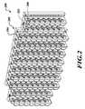
- FIG. 1shows a front view of an example high-intensity floodlight
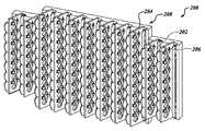
- FIG. 2shows a three dimensional view of an example high-intensity floodlight
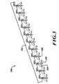
- FIG. 3shows a top view of an example high-intensity floodlight.
- the floodlightutilizes a right-angle reflector design which allows a plurality of LEDs to be mounted in a perpendicular orientation to the designed light output.
- the orientationadvantageously allows for more LEDs to be mounted than in a standard planar LED solution.
- the LEDsare mounted onto circuit cards (blades) which allow the LEDs to be activated and powered.
- the LEDsmay be mounted directly onto a heat spreader.
- the circuit cardsare mounted directly onto a heat spreader material with a high thermal conductivity, which functions as a heat sink fin.
- the heat sink finadvantageously reduces LED temperatures and therefore results in longer life and higher intensity.
- Perpendicular reflectorsare mounted onto the circuit boards.
- the perpendicular reflectorsare configured to reflect the light in the designed direction of the floodlight. For example, when activated, the LEDs shine light perpendicular to the direction of the floodlight and the reflectors reflect the light in the direction of the floodlight.
- FIG. 1shows a front view of an example high-intensity floodlight 100 .
- the high intensity floodlightincludes a plurality of blades 104 .
- the blades 104are, in one embodiment, circuit cards to power and control the LEDs 102 , but in alternate embodiments, the LEDs 102 may be mounted onto a heat spreader, or a thermal board made up of high conductive thermal materials.
- the LEDs 102are mounted on each side of the blades 104 , but may also be mounted only on one side of the blades 104 and are perpendicular to the direction of the floodlight 100 designed light output.
- a reflector 106is mounted on the blade 104 behind the LED 102 in order to reflect the light towards the floodlights 100 designed output.
- the reflector 106may be injection molded onto the blade 104 in alternate embodiments.
- FIG. 2shows a three dimensional view of an example high-intensity floodlight 200 .
- a plurality of LEDs 202 , and reflectors 206are mounted onto blades 204 .
- the blades 204are thermally coupled to a heat sink 208 .
- the heat sink 208draws heat from the blades 204 and dissipates the heat away from the LEDs 204 .
- FIG. 3shows a top view of an example high-intensity floodlight 300 .
- the flood light 300has a plurality of parallel blades 308 , with LEDs 306 and reflectors 304 . In alternate embodiments, there may be LEDs 306 and reflectors 304 on only one side of the blades 306 .
- the blades 306are thermally mounted to a heat sink 302 in order to dissipate heat away from the LED lights.
Landscapes
- Engineering & Computer Science (AREA)
- General Engineering & Computer Science (AREA)
- Physics & Mathematics (AREA)
- Microelectronics & Electronic Packaging (AREA)
- Optics & Photonics (AREA)
- Arrangement Of Elements, Cooling, Sealing, Or The Like Of Lighting Devices (AREA)
Abstract
Description
Some aerospace lighting applications require immense amounts of light to illuminate parts of the surrounding environment. A traditional lighting solution uses a large halogen lamp with an internal parabolic reflector. These lamps are fairly inefficient and require considerable quantities of electrical power to operate at the intended levels. Most of this power is radiated as heat and creates extremely high temperatures. These lamps must be isolated from other aircraft components so the heat does not interfere with other systems or injure maintenance personnel. Most importantly, halogen lights have a relatively short operating life and must be frequently replaced. Though the lamps themselves are not excessively expensive, replacing lamps involves maintenance time, which costs aircraft owners a significant amount due to aircraft downtime and labor.
A more recent solution for aerospace lighting utilizes High-Intensity Discharge (“HID”) systems. Though HID lamps have a longer operating life than their halogen counterparts, they have higher costs than a standard halogen lamp. The HID systems also require warm-up time of several minutes and the lamps cannot be easily flashed or quickly started.
Light emitting diode (LED) technology can also be used in aerospace lighting applications. LED solutions often have an operating life far greater than halogen or HID lamps. LED solutions are more efficient than halogen solutions and typically require less electrical power. LEDs also have a variety of possible operating conditions, allowing intensity levels and flash rates that are not easily attainable with halogen and HID solutions. Traditional LED solutions utilize one or more arrays of LEDs on a planar configuration. This limits the number of LEDs that can fit in a given size and complicates thermal management. These factors are both important as aircraft mounting installations are generally sized for the halogen solution, and the ability to properly manage heat at the LED directly impacts both the life and intensity of the LEDs.
Systems and methods for a high intensity light emitting diode (“LED”) floodlight are disclosed herein. The floodlight has a designed direction of output and includes an LED; an optical element; a blade; and a heat sink. The blade is mounted on the heat sink perpendicular to the designed direction of output. The blade has a free end with an LED and optic; and a fixed end coupled with the heat sink. The heat sink is configured to dissipate heat away from the LED located at the blade's free end. The blade is configured to activate the LED and, using the optic, redirect the light in the direction of the designed output of the floodlight.
The preferred and alternative embodiments of the present invention are described in detail below with reference to the following drawings:
Systems and methods for a high-intensity light emitting diode (LED) floodlight are disclosed herein. In one embodiment, the floodlight utilizes a right-angle reflector design which allows a plurality of LEDs to be mounted in a perpendicular orientation to the designed light output. The orientation advantageously allows for more LEDs to be mounted than in a standard planar LED solution. The LEDs are mounted onto circuit cards (blades) which allow the LEDs to be activated and powered. In an alternate embodiment, the LEDs may be mounted directly onto a heat spreader. The circuit cards are mounted directly onto a heat spreader material with a high thermal conductivity, which functions as a heat sink fin. The heat sink fin advantageously reduces LED temperatures and therefore results in longer life and higher intensity. Once heat enters the fin, it is conducted through the fin to the heat sink and convected through the surrounding air such that the heat is preferably dissipated to the ambient environment. Perpendicular reflectors are mounted onto the circuit boards. The perpendicular reflectors are configured to reflect the light in the designed direction of the floodlight. For example, when activated, the LEDs shine light perpendicular to the direction of the floodlight and the reflectors reflect the light in the direction of the floodlight.
While the preferred embodiment of the invention has been illustrated and described, as noted above, many changes can be made without departing from the spirit and scope of the invention. Accordingly, the scope of the invention is not limited by the disclosure of the preferred embodiment. Instead, the invention should be determined entirely by reference to the claims that follow.
Claims (7)
1. A high intensity light emitting diode floodlight, the floodlight having a designed direction of output, comprising:
a plurality of light emitting diodes;
a plurality of optical elements;
a plurality of blades comprising opposing sides having normal vectors perpendicular to the designed direction of output and the normal vectors are approximately parallel to each other, each of the blades having a free end and a fixed end; and
a heat sink thermally coupled to the fixed end of each of the blades, configured to dissipate heat away from the light emitting diodes,
wherein each of the sides receives a plurality of the light emitting diodes and optical elements,
wherein a single optical element is mounted adjacent to a single light emitting diode in order to reflect light produced by the light emitting diode in the designed direction of output.
2. The high intensity light emitting diode floodlight ofclaim 1 , wherein the blade is a circuit board.
3. The high intensity light emitting diode floodlight ofclaim 1 , wherein the blade is a thermally conductive board.
4. The high intensity light emitting diode floodlight ofclaim 1 , wherein the plurality of light emitting diodes located on a first one of the sides are arranged at a predefined distance from the free end of the respective blade.
5. The high intensity light emitting diode floodlight ofclaim 4 , wherein the plurality of light emitting diodes located on a second one of the sides are arranged at a predefined distance from the free end of the respective blade.
6. The high intensity light emitting diode floodlight ofclaim 5 , wherein the plurality of light emitting diodes located on the sides are arranged along an axis perpendicular to the designed direction of output, wherein the plurality of light emitting diodes located on the first side are not collocated along the axis as the plurality of light emitting diodes located on the second side.
7. The high intensity light emitting diode floodlight ofclaim 6 , wherein one or more of the light emitting diodes located on the first side are located on the axis at approximate midway points along the axis between two light emitting diodes located on the second side.
Priority Applications (2)
| Application Number | Priority Date | Filing Date | Title |
|---|---|---|---|
| US12/120,011US7857483B2 (en) | 2008-05-13 | 2008-05-13 | Systems and methods for a high-intensity light emitting diode floodlight |
| EP09158995.2AEP2131104B1 (en) | 2008-05-13 | 2009-04-28 | Systems and methods for high-intensity light emitting diode floodlight |
Applications Claiming Priority (1)
| Application Number | Priority Date | Filing Date | Title |
|---|---|---|---|
| US12/120,011US7857483B2 (en) | 2008-05-13 | 2008-05-13 | Systems and methods for a high-intensity light emitting diode floodlight |
Publications (2)
| Publication Number | Publication Date |
|---|---|
| US20090284976A1 US20090284976A1 (en) | 2009-11-19 |
| US7857483B2true US7857483B2 (en) | 2010-12-28 |
Family
ID=41017068
Family Applications (1)
| Application Number | Title | Priority Date | Filing Date |
|---|---|---|---|
| US12/120,011Active2029-01-20US7857483B2 (en) | 2008-05-13 | 2008-05-13 | Systems and methods for a high-intensity light emitting diode floodlight |
Country Status (2)
| Country | Link |
|---|---|
| US (1) | US7857483B2 (en) |
| EP (1) | EP2131104B1 (en) |
Cited By (7)
| Publication number | Priority date | Publication date | Assignee | Title |
|---|---|---|---|---|
| US20110205741A1 (en)* | 2010-02-24 | 2011-08-25 | Norimasa Suzuki | Lighting equipment |
| US20110205735A1 (en)* | 2010-02-24 | 2011-08-25 | Norimasa Suzuki | Light source unit and lighting equipment |
| US20120063125A1 (en)* | 2010-03-17 | 2012-03-15 | The Sloan Company, Inc. Dba Sloanled | Display case lighting |
| US8870413B2 (en) | 2012-07-30 | 2014-10-28 | Ultravision Holdings, Llc | Optical panel for LED light source |
| US8974077B2 (en) | 2012-07-30 | 2015-03-10 | Ultravision Technologies, Llc | Heat sink for LED light source |
| US9062873B2 (en) | 2012-07-30 | 2015-06-23 | Ultravision Technologies, Llc | Structure for protecting LED light source from moisture |
| US20160327232A1 (en)* | 2015-05-07 | 2016-11-10 | Focal Point, Llc | Diffuser for Luminaire |
Families Citing this family (11)
| Publication number | Priority date | Publication date | Assignee | Title |
|---|---|---|---|---|
| US9772099B2 (en) | 2009-10-05 | 2017-09-26 | Lighting Science Group Corporation | Low-profile lighting device and attachment members and kit comprising same |
| US8672518B2 (en) | 2009-10-05 | 2014-03-18 | Lighting Science Group Corporation | Low profile light and accessory kit for the same |
| US9581756B2 (en) | 2009-10-05 | 2017-02-28 | Lighting Science Group Corporation | Light guide for low profile luminaire |
| USD797980S1 (en) | 2010-05-06 | 2017-09-19 | Lighting Science Group Corporation | Low profile light |
| IT1402670B1 (en) | 2010-11-05 | 2013-09-13 | Sirio Panel Spa | LED LIGHTING DEVICE FOR AN AIRCRAFT, IN PARTICULAR FOR LANDING, TAKE-OFF, ROLLER, AND SEARCH OPERATIONS, AND AIRCRAFT INCLUDING THE LED LIGHTING DEVICE |
| US8485691B2 (en) | 2011-05-13 | 2013-07-16 | Lumenpulse Lighting, Inc. | High powered light emitting diode lighting unit |
| CZ22371U1 (en) | 2011-05-13 | 2011-06-13 | Ledwell S.R.O. | Light fitting, especially reflector light fitting with rectified light flow |
| JP2014089868A (en)* | 2012-10-30 | 2014-05-15 | Koito Mfg Co Ltd | Lighting appliance |
| KR102305233B1 (en)* | 2014-11-24 | 2021-09-27 | 쑤저우 레킨 세미컨덕터 컴퍼니 리미티드 | Light emitting module and lighting apparatus including the module |
| FR3036687B1 (en) | 2015-05-28 | 2019-01-25 | Zodiac Aero Electric | LIGHTING DEVICE FOR AN AIRCRAFT FOR THE INTEGRATION OF ADDITIONAL FUNCTIONS IN ITS CENTER |
| AU2021425715A1 (en)* | 2021-02-02 | 2023-08-24 | HELLA GmbH & Co. KGaA | Flashing light comprising a printed circuit board on which leds are arranged as light sources and reflectors for shaping the light emitted by the leds |
Citations (14)
| Publication number | Priority date | Publication date | Assignee | Title |
|---|---|---|---|---|
| US6452217B1 (en) | 2000-06-30 | 2002-09-17 | General Electric Company | High power LED lamp structure using phase change cooling enhancements for LED lighting products |
| US6525668B1 (en) | 2001-10-10 | 2003-02-25 | Twr Lighting, Inc. | LED array warning light system |
| WO2004097291A1 (en) | 2003-05-01 | 2004-11-11 | Allan Krogh Jensen | A tubular led light source |
| WO2005055328A1 (en) | 2003-12-05 | 2005-06-16 | Mitsubishi Denki Kabushiki Kaisha | Light emitting device and illumination instrument using the same |
| US7048412B2 (en)* | 2002-06-10 | 2006-05-23 | Lumileds Lighting U.S., Llc | Axial LED source |
| US7150553B2 (en)* | 2001-09-28 | 2006-12-19 | Osram Sylvania Inc. | Replaceable LED lamp capsule |
| US20070019432A1 (en)* | 2005-07-25 | 2007-01-25 | Takeshi Shimada | Led light source vehicular lamp |
| US7205719B2 (en) | 2004-12-27 | 2007-04-17 | Industrial Technology Research Institute | Light source with LED and optical protrusions |
| US7222995B1 (en)* | 2006-01-19 | 2007-05-29 | Bayco Products, Ltd. | Unitary reflector and lens combination for a light emitting device |
| US7281820B2 (en)* | 2006-01-10 | 2007-10-16 | Bayco Products, Ltd. | Lighting module assembly and method for a compact lighting device |
| US7300191B2 (en) | 2004-11-15 | 2007-11-27 | Koito Manufacturing Co., Ltd. | Vehicular lamp |
| US7331691B2 (en) | 2004-10-29 | 2008-02-19 | Goldeneye, Inc. | Light emitting diode light source with heat transfer means |
| DE102007044740A1 (en) | 2007-09-18 | 2008-05-08 | Daimler Ag | Vehicle headlight, has LEDs arranged at set of LED fields, and individually switched on and switched off and/or dimmable independently and groupwise, where optical unit is attached to each LED field |
| US7651240B2 (en)* | 2006-01-10 | 2010-01-26 | Bayco Products. Ltd. | Combination task lamp and flash light |
- 2008
- 2008-05-13USUS12/120,011patent/US7857483B2/enactiveActive
- 2009
- 2009-04-28EPEP09158995.2Apatent/EP2131104B1/enactiveActive
Patent Citations (14)
| Publication number | Priority date | Publication date | Assignee | Title |
|---|---|---|---|---|
| US6452217B1 (en) | 2000-06-30 | 2002-09-17 | General Electric Company | High power LED lamp structure using phase change cooling enhancements for LED lighting products |
| US7150553B2 (en)* | 2001-09-28 | 2006-12-19 | Osram Sylvania Inc. | Replaceable LED lamp capsule |
| US6525668B1 (en) | 2001-10-10 | 2003-02-25 | Twr Lighting, Inc. | LED array warning light system |
| US7048412B2 (en)* | 2002-06-10 | 2006-05-23 | Lumileds Lighting U.S., Llc | Axial LED source |
| WO2004097291A1 (en) | 2003-05-01 | 2004-11-11 | Allan Krogh Jensen | A tubular led light source |
| WO2005055328A1 (en) | 2003-12-05 | 2005-06-16 | Mitsubishi Denki Kabushiki Kaisha | Light emitting device and illumination instrument using the same |
| US7331691B2 (en) | 2004-10-29 | 2008-02-19 | Goldeneye, Inc. | Light emitting diode light source with heat transfer means |
| US7300191B2 (en) | 2004-11-15 | 2007-11-27 | Koito Manufacturing Co., Ltd. | Vehicular lamp |
| US7205719B2 (en) | 2004-12-27 | 2007-04-17 | Industrial Technology Research Institute | Light source with LED and optical protrusions |
| US20070019432A1 (en)* | 2005-07-25 | 2007-01-25 | Takeshi Shimada | Led light source vehicular lamp |
| US7281820B2 (en)* | 2006-01-10 | 2007-10-16 | Bayco Products, Ltd. | Lighting module assembly and method for a compact lighting device |
| US7651240B2 (en)* | 2006-01-10 | 2010-01-26 | Bayco Products. Ltd. | Combination task lamp and flash light |
| US7222995B1 (en)* | 2006-01-19 | 2007-05-29 | Bayco Products, Ltd. | Unitary reflector and lens combination for a light emitting device |
| DE102007044740A1 (en) | 2007-09-18 | 2008-05-08 | Daimler Ag | Vehicle headlight, has LEDs arranged at set of LED fields, and individually switched on and switched off and/or dimmable independently and groupwise, where optical unit is attached to each LED field |
Cited By (30)
| Publication number | Priority date | Publication date | Assignee | Title |
|---|---|---|---|---|
| US20110205741A1 (en)* | 2010-02-24 | 2011-08-25 | Norimasa Suzuki | Lighting equipment |
| US20110205735A1 (en)* | 2010-02-24 | 2011-08-25 | Norimasa Suzuki | Light source unit and lighting equipment |
| US20120063125A1 (en)* | 2010-03-17 | 2012-03-15 | The Sloan Company, Inc. Dba Sloanled | Display case lighting |
| US9524661B2 (en) | 2012-07-30 | 2016-12-20 | Ultravision Technologies, Llc | Outdoor billboard with lighting assemblies |
| US9589488B2 (en) | 2012-07-30 | 2017-03-07 | Ultravision Technologies, Llc | LED light assembly with three-part lens |
| US8974077B2 (en) | 2012-07-30 | 2015-03-10 | Ultravision Technologies, Llc | Heat sink for LED light source |
| US8985806B2 (en) | 2012-07-30 | 2015-03-24 | Ultravision Technologies, Llc | Heat sink for LED light source |
| US9062873B2 (en) | 2012-07-30 | 2015-06-23 | Ultravision Technologies, Llc | Structure for protecting LED light source from moisture |
| US9068738B2 (en) | 2012-07-30 | 2015-06-30 | Ultravision Technologies, Llc | Structure for protecting LED light source from moisture |
| US9212803B2 (en) | 2012-07-30 | 2015-12-15 | Ultravision Technologies, Llc | LED light assembly with three-part lens |
| US9234642B2 (en) | 2012-07-30 | 2016-01-12 | Ultravision Technologies, Llc | Billboard with light assembly for substantially uniform illumination |
| US9349307B1 (en) | 2012-07-30 | 2016-05-24 | Ultravision Technlologies, LLC | Forty-eight by fourteen foot outdoor billboard to be illuminated using only two lighting assemblies |
| US10891881B2 (en) | 2012-07-30 | 2021-01-12 | Ultravision Technologies, Llc | Lighting assembly with LEDs and optical elements |
| US9514663B2 (en) | 2012-07-30 | 2016-12-06 | Ultravision Technologies, Llc | Method of uniformly illuminating a billboard |
| US8870413B2 (en) | 2012-07-30 | 2014-10-28 | Ultravision Holdings, Llc | Optical panel for LED light source |
| US9542870B2 (en) | 2012-07-30 | 2017-01-10 | Ultravision Technologies, Llc | Billboard and lighting assembly with heat sink and three-part lens |
| US8870410B2 (en) | 2012-07-30 | 2014-10-28 | Ultravision Holdings, Llc | Optical panel for LED light source |
| US9659511B2 (en) | 2012-07-30 | 2017-05-23 | Ultravision Technologies, Llc | LED light assembly having three-part optical elements |
| US9685102B1 (en) | 2012-07-30 | 2017-06-20 | Ultravision Technologies, Llc | LED lighting assembly with uniform output independent of number of number of active LEDs, and method |
| US9734738B2 (en) | 2012-07-30 | 2017-08-15 | Ultravision Technologies, Llc | Apparatus with lighting units |
| US9732932B2 (en) | 2012-07-30 | 2017-08-15 | Ultravision Technologies, Llc | Lighting assembly with multiple lighting units |
| US9734737B2 (en) | 2012-07-30 | 2017-08-15 | Ultravision Technologies, Llc | Outdoor billboard with lighting assemblies |
| US9812043B2 (en) | 2012-07-30 | 2017-11-07 | Ultravision Technologies, Llc | Light assembly for providing substantially uniform illumination |
| US9947248B2 (en) | 2012-07-30 | 2018-04-17 | Ultravision Technologies, Llc | Lighting assembly with multiple lighting units |
| US10460634B2 (en) | 2012-07-30 | 2019-10-29 | Ultravision Technologies, Llc | LED light assembly with transparent substrate having array of lenses for projecting light to illuminate an area |
| US10223946B2 (en) | 2012-07-30 | 2019-03-05 | Ultravision Technologies, Llc | Lighting device with transparent substrate, heat sink and LED array for uniform illumination regardless of number of functional LEDs |
| US10339841B2 (en) | 2012-07-30 | 2019-07-02 | Ultravision Technologies, Llc | Lighting assembly with multiple lighting units |
| US10410551B2 (en) | 2012-07-30 | 2019-09-10 | Ultravision Technologies, Llc | Lighting assembly with LEDs and four-part optical elements |
| US10030830B2 (en)* | 2015-05-07 | 2018-07-24 | Focal Point, Llc | Diffuser for luminaire |
| US20160327232A1 (en)* | 2015-05-07 | 2016-11-10 | Focal Point, Llc | Diffuser for Luminaire |
Also Published As
| Publication number | Publication date |
|---|---|
| EP2131104B1 (en) | 2015-07-15 |
| US20090284976A1 (en) | 2009-11-19 |
| EP2131104A3 (en) | 2010-07-14 |
| EP2131104A2 (en) | 2009-12-09 |
Similar Documents
| Publication | Publication Date | Title |
|---|---|---|
| US7857483B2 (en) | Systems and methods for a high-intensity light emitting diode floodlight | |
| US8408737B2 (en) | Light emitting diode sign lighter | |
| US8382334B2 (en) | Lighting apparatus with heat dissipation system | |
| KR100857058B1 (en) | Cooling structure of street light using light emitting diode | |
| US7780320B2 (en) | Street lamp system | |
| US9228724B2 (en) | Modular LED lamp structure with replaceable modules | |
| US9383084B2 (en) | Mounting system for an industrial light | |
| CN203036430U (en) | Illuminating apparatus | |
| KR100908578B1 (en) | LED module for electric vehicle lighting and LED lamp for electric vehicle | |
| KR101410604B1 (en) | Solid cooling structure of LED lighting using nature air flow | |
| US10253965B2 (en) | Heated lens lighting arrangement with optic cable extending from light source to an opening in heat exchanger | |
| JP5798070B2 (en) | Aviation Obstruction Light | |
| KR101034481B1 (en) | Luminaires to prevent frost formation | |
| KR100864585B1 (en) | Lamp structure using light emitting diode | |
| KR20040081846A (en) | LED lamp for signal light | |
| KR101091577B1 (en) | LED luminaires with improved coverage and heat dissipation | |
| CN102147060B (en) | Lamp fitting | |
| TWM481848U (en) | Automobile lamp | |
| CN220506555U (en) | Automobile headlamp | |
| US10247403B2 (en) | Heat sink and lighting apparatus | |
| KR20110034744A (en) | LED lighting device | |
| KR101167044B1 (en) | Security light fixture with reflector | |
| KR101587834B1 (en) | Lamp For Outdoor | |
| KR101354475B1 (en) | Boundary led light | |
| KR200469521Y1 (en) | Heat-Dissipating Device of led lamp |
Legal Events
| Date | Code | Title | Description |
|---|---|---|---|
| AS | Assignment | Owner name:HONEYWELL INTERNATIONAL INC., NEW JERSEY Free format text:ASSIGNMENT OF ASSIGNORS INTEREST;ASSIGNORS:STORCH, DAVID ROBERT;SINGER, JEFFREY M.;BARNETT, DAVID;REEL/FRAME:020942/0900 Effective date:20080513 | |
| STCF | Information on status: patent grant | Free format text:PATENTED CASE | |
| FPAY | Fee payment | Year of fee payment:4 | |
| MAFP | Maintenance fee payment | Free format text:PAYMENT OF MAINTENANCE FEE, 8TH YEAR, LARGE ENTITY (ORIGINAL EVENT CODE: M1552) Year of fee payment:8 | |
| MAFP | Maintenance fee payment | Free format text:PAYMENT OF MAINTENANCE FEE, 12TH YEAR, LARGE ENTITY (ORIGINAL EVENT CODE: M1553); ENTITY STATUS OF PATENT OWNER: LARGE ENTITY Year of fee payment:12 |