US7857214B2 - Intelligent track system for mounting electronic equipment - Google Patents
Intelligent track system for mounting electronic equipmentDownload PDFInfo
- Publication number
- US7857214B2 US7857214B2US11/873,236US87323607AUS7857214B2US 7857214 B2US7857214 B2US 7857214B2US 87323607 AUS87323607 AUS 87323607AUS 7857214 B2US7857214 B2US 7857214B2
- Authority
- US
- United States
- Prior art keywords
- rack
- sensor
- electronic device
- shelving
- spaces
- Prior art date
- Legal status (The legal status is an assumption and is not a legal conclusion. Google has not performed a legal analysis and makes no representation as to the accuracy of the status listed.)
- Expired - Fee Related, expires
Links
Images


Classifications
- H—ELECTRICITY
- H05—ELECTRIC TECHNIQUES NOT OTHERWISE PROVIDED FOR
- H05K—PRINTED CIRCUITS; CASINGS OR CONSTRUCTIONAL DETAILS OF ELECTRIC APPARATUS; MANUFACTURE OF ASSEMBLAGES OF ELECTRICAL COMPONENTS
- H05K7/00—Constructional details common to different types of electric apparatus
- H05K7/14—Mounting supporting structure in casing or on frame or rack
- H05K7/1485—Servers; Data center rooms, e.g. 19-inch computer racks
- H05K7/1498—Resource management, Optimisation arrangements, e.g. configuration, identification, tracking, physical location
- G—PHYSICS
- G06—COMPUTING OR CALCULATING; COUNTING
- G06F—ELECTRIC DIGITAL DATA PROCESSING
- G06F1/00—Details not covered by groups G06F3/00 - G06F13/00 and G06F21/00
- G06F1/16—Constructional details or arrangements
- G06F1/18—Packaging or power distribution
- G06F1/181—Enclosures
- G—PHYSICS
- G06—COMPUTING OR CALCULATING; COUNTING
- G06F—ELECTRIC DIGITAL DATA PROCESSING
- G06F1/00—Details not covered by groups G06F3/00 - G06F13/00 and G06F21/00
- G06F1/16—Constructional details or arrangements
- G06F1/18—Packaging or power distribution
- G06F1/183—Internal mounting support structures, e.g. for printed circuit boards, internal connecting means
Definitions
- the present inventionrelates generally to electronic equipment cabinets and racks, and more particularly to racks having multiple mounting locations for the equipment.
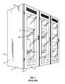
- the equipmentis coupled to racks as shown in FIG. 1 .
- the equipmentis generally organized in a cabinet 2 of standard dimensions with multiple vertical racks 4 to support columns of equipment.
- a plurality of standardized preset spaces 26(where three (3) standardized spaces are sometimes referred to as a “U” space) can be used to mount the equipment.
- the cabinet 2generally includes sides 6 , back 8 , top 10 , bottom 12 , and front 14 .
- the front 14generally includes a door to gain access to the equipment therein. Power rails, uninterruptible power supplies, and other features can be coupled to the racks or cabinet.
- ITinformation technology
- the systemdoes not provide actual and direct feedback to the software program and thus can only provide such information based on the operator input. If the data is incorrectly entered, so that equipment is actually in a different location, then the software predictive capabilities are based on error and are potentially harmful by providing misleading information. It is not uncommon for electronic equipment to be assigned to a given location in a rack, but the operator is unable to install the equipment in that location because a previous operator installed an earlier piece of electrical equipment in that location. The technician then installs the new equipment in yet a different location than intended and the data is not updated in the records, thus perpetuating the problem. Additionally, it is not uncommon for equipment to migrate from location to location or rack to rack as the IT computing environment is chaotic and ever changing. Thus, tracking these changes is difficult, labor-intensive, and time consuming.
- the present inventionprovides an intelligent track system generally mounted in a network, server, or telecom rack/enclosure rack rail that can sense the spaces, such as “U” spaces, used by electronic equipment, shelving, or blanking panels and provide such information to a remote location.
- Information technology (IT) managers and other decision-makerscan remotely view the actual available spaces and determine appropriate locations for installing additional equipment. Criteria can be based on actual available space and for some embodiments in conjunction with predictive or actual sensed temperatures proximate to the spaces, available cooling capacity, power loads, and available power capacity.
- the intelligent mounting track systemcan include a plurality of sensors mounted along the rack surfaces that collectively or individually uniquely identify which spaces are occupied. The information can be communicated to an electronic processor with software to interpret the data and indicate space utilization.
- the disclosureprovides a system for indicating the presence of electronic equipment, shelving, blanking panels, or a combination thereof, comprising: a rack having a plurality of mounting spaces adapted to mount a plurality of electronic devices, shelving, or blanking panels; a plurality of sensors coupled to a rack along a length of the rack in alignment with the spaces, at least one sensor having a characteristic uniquely identified with the sensor to differentiate the sensor from other sensors coupled to the rack, and a location of the at least one sensor is known relative to the rack; at least one communication link coupled to the at least one sensor; and an electronic processor coupled to the communication link and adapted to receive information from the at least one sensor and determine a location of at least one electronic device, shelving, or blanking panel mounted to the rack by correlation to the location of at least one sensor when the at least one electronic device, shelving, or blanking panel is mounted to the rack.
- the disclosurealso provides a method for indicating the presence of electronic equipment, shelving, a blanking panel, or combination thereof, coupled to one or more mounting spaces in a rack, the rack having a plurality of sensors coupled to the rack and corresponding to the spaces along a length of the rack, and at least one conductive element coupled to at least one sensor with a location of the at least one sensor known relative to the rack, comprising: mounting at least one electronic device, shelving, or blanking panel to at least one of the mounting spaces in the rack; causing at least one of the sensors to receive information by the mounting of the at least one electronic device, shelving, or blanking panel, the at least one sensor having a unique characteristic to differentiate the sensor from other sensors coupled to the rack and the sensor having a known location; communicating the information about the mounting of the at least one electronic device, shelving, or blanking panel to an electronic processor; and establishing a location of the at least one electronic device, shelving, or blanking panel mounted to the rack based on the location of the at least one sensor.
- FIG. 1illustrates in perspective view an existing stack of cabinets to support electronic equipment.
- FIG. 2is a schematic diagram of an exemplary system having an intelligent track system.
- FIG. 3is a schematic diagram of the cabinet and rack of the exemplary system of FIG. 2 .
- FIG. 4is a schematic diagram of details of the intelligent track system of FIGS. 2 and 3 .
- FIG. 5is a schematic flowchart of a decision process for remotely selecting the appropriate location for equipment.
- Applicantshave created an intelligent mounting track system that can sense the “U” spaces used by electrical equipment, such as on a rack in an electrical cabinet, and provide such information to a remote location.
- the informationcan be communicated to an electronic processor with software to interpret the information and indicate space utilization to assist information technology (“IT”) managers and other decision-makers in determining more accurately available locations for additional equipment from remote locations without physical inspection.
- ITinformation technology
- FIG. 2is a schematic diagram of an exemplary system having an intelligent track system.
- the system 20includes a rack with mounting spaces for mounting electronic devices, one or more sensors for sensing at least the presence of an electronic device, a communications link coupled to the sensor, and an electronic processor coupled to the communications link to receive information on the status of the sensor and the current location of at least one of the electronic devices mounted to the rack.
- Such electronic equipmentcan include servers, routers, and other devices generally associated with computer and electronic systems.
- Coupledcan include any method or device for securing, binding, bonding, fastening, attaching, joining, inserting therein, forming thereon or therein, communicating, or otherwise associating, for example, mechanically, magnetically, electrically, chemically, directly or indirectly with intermediate elements, one or more pieces of members together and can further include integrally forming one functional member with another.
- the couplingcan occur in any direction, including rotationally.
- one or more cabinets 2can include one or more racks 22 , each rack having a rack rail 24 .
- the rack railcan have mounting spaces for attaching one or more electronic devices 50 to the rack rail.
- a grouping of such mounting spacescan be generally referenced using current terminology as a “U” space that generally includes three mounting spaces, shown in more detail in FIG. 4 . It is to be understood, however, that such concepts of the present inventions are not limited to any particular number of spaces or the particular nomenclature of a “U”, and such terminology is used for ease of reference with current terminology.
- a power module 16can provide power to the electronic devices mounted to the rack rail.
- one or more wireless transceivers 46can be coupled to the rack 22 , such as on a cabinet surface.
- the term “transceiver”is used broadly herein to include a receiver, a transmitter, or a combination thereof.
- the wireless transceiver 46can transmit various data received from the rack, the cabinet, or a combination thereof. Such characteristics can include, without limitation, a thermal load, such as cabinet temperature, electrical load, humidity, electronic device data from electronic devices mounted to the rack, and other information. In some embodiments, the information can be transmitted through wired systems.
- a communication link 36can provide communications between various components of the system 20 .
- the communication linkcan include an ethernet, a local area network, wide area network, and other network configurations known to those with ordinary skill in the art.
- the communication link 36is to be construed broadly and includes wired and/or wireless systems and communications capabilities.
- the communicationcan occur through various modes and software including, without limitation, Hyper Tech Transfer Protocol (HTTP), Simple Network Management Protocol (SNMP), through email, or through BAC/IP (Back Net Over IP), and other communication protocols.
- the communication linkcan include branch communication links.
- a communication link 36 A between the power module 16 and other components of the systemcan provide information on the electrical load from the devices coupled thereto. Such information can provide data to correlate or calculate the electrical loads and compare electrical load capacities of the particular rack to which one or more electronic devices are mounted.
- the electrical loadcan be used to provide information on the thermal load as well.
- the communication link 36can provide information to an interface 18 having various modules for directing input and output, digital and analog signals, receiving wireless communications, providing internet communications, and other functions.
- the interface 18can communicate with other components of the system through a communication link 36 B.
- One such suitable interfaceis known as an IntelliRack produced by Liebert Corporation of Columbus, Ohio.
- the IntelliRack systemis designed to accept modules that can perform the various functions such as those referenced above.
- an interface module 18 Acan include a link card adapted to gather data and output information to a web network.
- An interface module 18 Bcan be an Intellislot-4 having an EIA 232 interface.
- An interface module 18 Ccan include an input/output card, such as one that is particularly adapted to receive analog and digital inputs.
- an interface module 18 Dcan also be an Intellislot input/output card designed to provide additional output to various other components of the system.
- An interface module 18 Ecan accept wireless data for communicating such data to other system components.
- the interface module 18 Ecan be coupled to a wireless transceiver 48 .
- the electronic processor 38can be used to process information provided from the rack 22 , directly or through the interface 18 .
- the electronic processor 38generally includes a processing portion 40 that can execute the programs and perform system and data integrity checks, and may be software, firmware, or hardware based.
- the electronic processor 38also generally includes a memory portion 42 .
- the memory portion 42can be integral to the electronic processor 38 or separate therefrom. Further, the memory portion 42 can be located distally from the processing portion 40 and coupled through electronic communications.
- the memory portion 42can include various types of memory, such as dynamic, random access, read-only, and other electronic data storage media and systems.
- the memory portion 42can further store the various software programs used by the processing portion 40 .
- An output 44such as a display, can provide information to the decision-maker.
- the processorcan be coupled to the communication link 36 through a communication link 36 C.
- the communication link 36can also provide the data to other processors either on site or at remote locations.
- the processorscan include network management systems through software, firmware, or hardware.
- the electronic processor 38can examine and determine space availability for electronic devices to be coupled to the rack. Further, the electronic processor can be used to provide data on the system characteristics, such as electrical and thermal loads and other characteristics.
- the electronic processorcan also be used to track the particular electronic device installed in a particular rack location, if the identity of the electronic device is provided and traced. Thus, if the electronic device is moved from location to location, the processor can provide such data to a decision-maker.
- Various softwarecan be used to display a system status of the various components, including the status of electronic devices mounted to particular rack locations, the status of the thermal and/or electrical loads, and other information.
- the datacan be displayed in what is commonly known as a “dashboard.”
- One available dashboardis known as OpenComms Nform which provides monitoring by network infrastructure.
- the softwareis available from Liebert Corporation.
- Some dashboardscan include a monitoring program, such as SiteScan Web also available from Liebert Corporation.
- FIG. 3is a schematic diagram of the cabinet and rack of the exemplary system of FIG. 2 .
- FIG. 3provides additional details of the rack.
- the system 2includes one or more racks 22 with a rack rail 24 .
- a track sensor system 28can be mounted to the rack rail 24 .
- the track sensor system 28can include a plurality of sensors 32 distributed along a track 30 .
- a power module 16can be mounted to the cabinet 2 to provide power for electronic devices mounted to the rack.
- the track sensor system 28can provide information to an electronic processor 38 and the communication link 36 .
- the power module 16can also provide information on electrical load to the processor 38 , where a transceiver 46 coupled to the electrical load can transmit data to a transceiver 48 coupled to the processor.
- the wireless transceiver 46can provide further or other information as is appropriate for the particular system to the processor 38 .
- a cabinet 2 Aillustrates a plurality of the track sensors 32 A, 32 B, 32 C, 32 D, through 32 N, collectively referenced herein as sensor or sensors 32 .
- an electronic device 50 , blanking panel 70 , or shelving 72 , or a combination thereof that are mounted in one or more of the available rack positionscan cooperate with the one or more sensors 32 , so that the system can determine the presence of an electronic device mounted to the particular location correlating to the particular sensor.
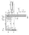
- FIG. 4is a schematic diagram of details of the intelligent track system of FIGS. 2 and 3 .
- the schematicillustrates at least one embodiment that is able to track the location of one or more particular electronic devices 50 mounted to the rack 22 at various spaces 26 .
- Such spacesare generally defined in current terminology as a “U” space that generally includes three mounting spaces 26 . It is to be understood, however, that such concepts of the present inventions are not limited to any particular number of spaces or the particular nomenclature of a “U”, and such terminology is used for ease of reference with current terminology.
- a decision-makercan determine the availability of open locations for electronic equipment.
- the track sensor system 38can include a strip of sensors electrically coupled to one or more busses or other conductive elements 35 A, 35 B, and other paths. Each sensor generally has a unique characteristic that allows the system to identify the particular sensor from other sensors in the rack and possibly from other racks. Without limitation, each sensor can be numbered to correspond to various “U” number indications on the track 30 of the track sensor system 28 .
- the track sensor system 28can include a micro-controller 34 with communication capabilities to transfer data through a communication link 36 F and then to the communication link 36 .
- the communicationcan occur directly to the communication link 36 or through the power module 16 , if the power module has such capabilities, or a combination thereof.
- the power modulecan indicate a “smart power chip” that includes sensors 54 for sensing electrical loads on the power module 16 . Such electrical loads can be sensed on an individual electrical load basis or for the overall power module.
- the power module 16can communicate such information through a communication link 36 A to the overall communication link 36 , and then to the processor 38 and/or interface 18 .
- the senor 32can include a resistance sensor that senses the conductive presence of an electronic device mounted to the location corresponding to the associated sensor. By mounting the electronic device, the sensor can be contacted, pressed, or otherwise activated to contact a conductive element, such as conductive elements 35 A, 35 B, to indicate a change in resistance in the presence of a device mounted thereto. For example, a voltage can be applied to the conductive element to establish a first resistance in a first mode. When the sensor is activated and contacts the conductive element in a second mode, a change in the conductive path and a change in resistance occurs.
- each sensorcould have a unique resistance characteristic so that a change in resistance could be mapped to the respective sensor and identify the particular location of the change.
- the changecan be registered with the processor 38 to indicate the presence of an electronic device.
- the changecan indicate the presence of a device with little to no knowledge of the particular specifics of the device, such as a model and serial number.
- the senorcan be activated to accept non-contact or non-conductive information, such as from radio frequency identification technology (“RFID”).
- RFIDradio frequency identification technology
- the sensorcan be an RFID reader that can receive signals from an RFID identifier 56 .
- the RFID identifier 56such as an RFID tag, can be mounted to the electronic device 50 .
- the sensitivity of the receiver and tagcan be adjusted, so that the receiver only receives a signal from the tag, if the electronic device is mounted in the location that corresponds to the particular receiver.
- a mounting scheme for an electronic deviceis through one or more device mounting openings 66 which can be mounted to rail 22 in a given “U” space.
- the identifier 56can include, for example, one or more sensor mounting openings 58 aligned with the one or more device mounting openings 66 to facilitate mounting the electronic device to the rack in the relevant spaces 26 with the identifier 56 .
- the sensor resistance, and RFID reader and tagare exemplary and non limiting embodiments.
- Another examplecould include a sensor having a magnetic reader to sense a change in an associated magnetic field with the mounting of the electronic device. The change can be communicated through the system.
- Other examples of tracking technologiescan be used and are contemplated.
- the corresponding sensors 32can sense the presence of the electronic device and provide information on the presence of the electronic device throughout the system 20 .
- the identifier 56can be coupled to the electronic device 50 in a variety of ways.
- the identifiercan be coupled by an adhesive, fastened through a screw, rivet, or both, or other mounting hardware.
- the identified 56will remain with the electronic device 50 . Therefore, if the device moves from one U space to another U space within a rack, or from one rack to an alternative rack, the location of the electronic device can be tracked through the system 20 .
- the identifiercan also be used at other resource areas related to the system 20 , such as at a repair station or in an inventory room.
- the identifier 56can further include other information specific to the electronic device, such as historical information on repair, usage, health, as well as identification information such as model number, serial number and application to which the electronic device is assigned.
- the datacan be communicated through communication links, such as communication link 36 G.
- the communication link 36 Gcan, for example, represent a power line between the power module 16 and the electronic device 50 using technology that communicates information over the power line at frequencies other than the line frequency.
- a blanking panel 70can fill unused vertical space in a rack to better control the air flow through the rack.
- the blanking panel 70can be associated or otherwise coupled to one or more sensors 32 to indicate its presence similar to the electronic device 50 , with the general exception that specific data regarding the unit may not be communicated via a communication link 36 G as can be done for the electronic device. For example, the relevant sensor can be pressed a predetermined number of times to indicate the presence of the blanking panel for that sensor. If the blanking panel extends over multiple sensors, then multiple sensors can be actuated. Shelving 72 can also be used in the system and its presence indicated through the associated one or more sensors 32 .
- the track sensor system 28can include one or more configuration controls 68 , such as 68 A, 68 B, through 68 N.
- each sensor 32can include a corresponding configuration control 68 .
- the configuration controlcan include, without limitation, a button that can be pressed by an operator or can be activated by some other device that can be operated either manually or automatically from a remote site.
- the control buttoncan be used to activate a corresponding sensor 32 or can be used to override the sensor and indicate that the space is occupied by a blanking panel 70 , shelving 72 , or provide some other occupied indication.
- the indicatorcan change colors depending on the particular mode in which it is used.
- a power supply 62can provide power through a power feed 64 to the power module 16 .
- the power supplycan be an AC power supply, DC power supply, or a combination thereof.
- a power usage sensor 65may also be provided in the system 20 .
- the power usage sensor 65may be adapted to sense a power usage of the rack 22 and provide power usage input to the electronic processor 38 .
- Such a power usage sensor 65may comprise a current transformer (CT) coupled at least partially around the power feed 64 to the rack 22 .
- CTcurrent transformer
- the current transformer 65may be adapted to sense a magnetic field around the power feed 64 dependent on an amount of current therethrough.
- FIG. 5is a schematic flowchart of a decision process for remotely selecting the appropriate location for equipment.
- the flow chartillustrates an exemplary decision process for locating new equipment. It is to be understood that the decision process could be modified as is known to those with ordinary skill in the art to include relocation of equipment, reinstallation of equipment that has been repaired, the need for servicing equipment based upon performance of the equipment at the installed location, and other decision processes that stem from the system described above. Thus, the illustrated flow chart is only exemplary and provided for the convenience of the reader. Further, the decisions can be made by a human operator or automatically through logic functions that can be programmed or learned by electronic processors. Thus, whether manual or automatic, the decision is made by a decision-maker.
- a block 80signifies the desire of a decision-maker to install a new server, a repaired server, a different server, or other electronic device into a data center.
- a decision block 82indicates that the decision-maker reviews information available from the processor 38 described above to obtain possible available locations for mounting the electronic device. If no location is available, then as illustrated in block 84 , the decision-maker can use an alternative site, or add or reconfigure the existing deployment and infrastructure of the electronic devices or system. If multiple locations are potentially available, then the decision-maker can choose one or more racks as shown in block 86 .
- a decision block 88shows that the decision-maker can review available power in the selected racks to see which rack or racks can support additional electrical loads.
- the decision-makerreturns to the block 84 that recommends choosing an alternative site or reconfiguring the infrastructure. If multiple racks are available and can support the electrical load, then block 90 indicates that a choice of the particular racks can be made. The system can be further queried in order to select qualified racks that have available power within allowable thermal limits for the particular rack. If all the racks are near their allowable thermal limits, then the decision is again referred to block 84 that recommends an alternative site or reconfiguration. If one rack has available power and is within its allowable thermal limit, then the decision can be made to use that rack and the particular available U space in block 94 . If multiple racks still are suitable, then the decision-maker can select the rack from the available racks and the particular available U space.
- a work order in block 96is issued.
- An identifierif appropriate, is coupled to the electronic device in block 98 and the electronic device is installed in the selected rack and U space in block 100 .
- the systemcan be configured to only monitor, for example, available space, and track different electronic devices based on the available space. Further, other embodiments can be configured to sense only the available space, and the available power or the allowable thermal limit, and make a decision based on such selected criteria. Further, a decision-maker may choose available space and power so that if only one rack was available, the decision may be made to choose that rack regardless of thermal limits. Other variations are possible.
- Coupledcan include any method or device for securing, binding, bonding, fastening, attaching, joining, inserting therein, forming thereon or therein, communicating, or otherwise associating, for example, mechanically, magnetically, electrically, chemically, directly or indirectly with intermediate elements or by wireless transmission, one or more pieces of members together and can further include without limitation integrally forming one functional member with another in a unity fashion.
- the couplingcan occur in any direction, including rotationally.
Landscapes
- Engineering & Computer Science (AREA)
- Theoretical Computer Science (AREA)
- Computer Hardware Design (AREA)
- General Engineering & Computer Science (AREA)
- Power Engineering (AREA)
- Human Computer Interaction (AREA)
- Physics & Mathematics (AREA)
- General Physics & Mathematics (AREA)
- Microelectronics & Electronic Packaging (AREA)
- Arrangements For Transmission Of Measured Signals (AREA)
- Power Sources (AREA)
Abstract
Description
Claims (18)
Priority Applications (3)
| Application Number | Priority Date | Filing Date | Title |
|---|---|---|---|
| US11/873,236US7857214B2 (en) | 2007-04-26 | 2007-10-16 | Intelligent track system for mounting electronic equipment |
| EP07863651AEP2140332B1 (en) | 2007-04-26 | 2007-10-30 | Intelligent track system for mounting electronic equipment |
| PCT/US2007/082996WO2008133712A1 (en) | 2007-04-26 | 2007-10-30 | Intelligent track system for mounting electronic equipment |
Applications Claiming Priority (2)
| Application Number | Priority Date | Filing Date | Title |
|---|---|---|---|
| US91411907P | 2007-04-26 | 2007-04-26 | |
| US11/873,236US7857214B2 (en) | 2007-04-26 | 2007-10-16 | Intelligent track system for mounting electronic equipment |
Publications (2)
| Publication Number | Publication Date |
|---|---|
| US20080265722A1 US20080265722A1 (en) | 2008-10-30 |
| US7857214B2true US7857214B2 (en) | 2010-12-28 |
Family
ID=39886088
Family Applications (1)
| Application Number | Title | Priority Date | Filing Date |
|---|---|---|---|
| US11/873,236Expired - Fee RelatedUS7857214B2 (en) | 2007-04-26 | 2007-10-16 | Intelligent track system for mounting electronic equipment |
Country Status (3)
| Country | Link |
|---|---|
| US (1) | US7857214B2 (en) |
| EP (1) | EP2140332B1 (en) |
| WO (1) | WO2008133712A1 (en) |
Cited By (45)
| Publication number | Priority date | Publication date | Assignee | Title |
|---|---|---|---|---|
| US20100328849A1 (en)* | 2009-06-25 | 2010-12-30 | Ewing Carrel W | Power distribution apparatus with input and output power sensing and method of use |
| US20110078480A1 (en)* | 2009-09-25 | 2011-03-31 | International Business Machines Corporation | Energy-efficient server location determination |
| US20110078290A1 (en)* | 2009-09-25 | 2011-03-31 | International Business Machines Corporation | Energy-efficient server location determination for configuration changes |
| US20110084839A1 (en)* | 2009-10-14 | 2011-04-14 | Noah Groth | Data center equipment location and monitoring system |
| US20110213735A1 (en)* | 2010-02-26 | 2011-09-01 | International Business Machines Corporation | Selecting An Installation Rack For A Device In A Data Center |
| US20110215946A1 (en)* | 2010-03-08 | 2011-09-08 | Jerry Aguren | Sensing environmental conditions using RFID |
| US20110304211A1 (en)* | 2010-06-09 | 2011-12-15 | Microsoft Corporation | Rack-Based Uninterruptible Power Supply |
| US20120031965A1 (en)* | 2009-02-19 | 2012-02-09 | Rittal Gmbh & Co. Ag | Switchgear cabinet or rack |
| US20120161938A1 (en)* | 2009-08-05 | 2012-06-28 | Dieter Kilian | Receiving device with rfid detection of built-in components held therein, and rfid detection method |
| US20120166693A1 (en)* | 2010-07-26 | 2012-06-28 | Raritan Americas, Inc. | Intelligent Asset Management System |
| US20120262861A1 (en)* | 2011-04-12 | 2012-10-18 | Wistron Corporation | Rack with a Power Distribution Unit |
| US8487473B2 (en) | 2010-06-24 | 2013-07-16 | Microsoft Corporation | Hierarchical power smoothing |
| US20140031971A1 (en)* | 2012-07-25 | 2014-01-30 | International Business Machines Corporation | Lift apparatus for stable placement of components into a rack |
| US8651379B2 (en) | 2009-02-19 | 2014-02-18 | Rittal Gmbh & Co. Kg | Switchgear cabinet or rack |
| US8659879B2 (en) | 2009-02-19 | 2014-02-25 | Rittal Gmbh & Co. Kg | Switchgear cabinet or rack |
| US8659878B2 (en) | 2009-02-19 | 2014-02-25 | Rittal Gmbh & Co. Kg | Switchgear cabinet or rack |
| US8782443B2 (en) | 2010-05-25 | 2014-07-15 | Microsoft Corporation | Resource-based adaptive server loading |
| US20140297855A1 (en)* | 2011-12-17 | 2014-10-02 | David A. Moore | Determining Rack Position of Device |
| US20140368311A1 (en)* | 2011-12-21 | 2014-12-18 | Rajeev Grover | Proper Installation Determination Based on RFID |
| US20150017911A1 (en)* | 2013-07-09 | 2015-01-15 | Hong Fu Jin Precision Industry (Shenzhen) Co., Ltd. | Monitoring system and monitoring method |
| US20150026621A1 (en)* | 2013-07-18 | 2015-01-22 | Netapp, Inc. | System and Method for Planning an Implementation of a Computing System |
| US8952566B2 (en) | 2010-10-26 | 2015-02-10 | Microsoft Technology Licensing, Llc | Chassis slots accepting battery modules and other module types |
| US20150109132A1 (en)* | 2013-10-18 | 2015-04-23 | Delta Electronics, Inc. | Device management module, remote management module and device management system employing same |
| US9146029B2 (en) | 2012-06-15 | 2015-09-29 | RTC Industries, Incorporated | Power supply with mechanical connections |
| US20150347259A1 (en)* | 2012-05-09 | 2015-12-03 | Pacific Industrial Co., Ltd. | Server monitoring device and server monitoring system |
| US9225131B2 (en) | 2012-06-15 | 2015-12-29 | RTC Industries, Incorporated | Low voltage power supply with magnetic connections |
| US9360196B2 (en) | 2012-06-15 | 2016-06-07 | Rtc Industries, Inc. | Low voltage power supply for a merchandise display system |
| US20160164856A1 (en)* | 2013-12-17 | 2016-06-09 | Lenovo Enterprise Solutions (Singapore) Pte. Ltd. | Dynamic activation of service indicators based upon service personnel proximity |
| US20160262283A1 (en)* | 2010-12-23 | 2016-09-08 | Amazon Technologies, Inc. | System with movable computing devices |
| US20170111451A1 (en)* | 2015-10-15 | 2017-04-20 | LiThul LLC | Methods and Apparatus For Remotely Monitoring Access To Rack Mounted Server Cabinets |
| US9772663B2 (en) | 2015-10-15 | 2017-09-26 | LiThul LLC | System and method for distributing power to rack mounted servers |
| US20180027376A1 (en)* | 2016-07-22 | 2018-01-25 | Intel Corporation | Configurable Computing Resource Physical Location Determination |
| US20180070475A1 (en)* | 2010-09-20 | 2018-03-08 | Amazon Technologies, Inc. | System with rack-mounted ac fans |
| US9952261B2 (en) | 2009-03-04 | 2018-04-24 | Server Technology, Inc. | Monitoring power-related parameters in a power distribution unit |
| TWI631473B (en)* | 2017-03-13 | 2018-08-01 | 廣達電腦股份有限公司 | Device in data center and system and method for determining location |
| US10264697B2 (en) | 2015-10-13 | 2019-04-16 | Daniel Fazenda Freire | Protective cabinet for storage and protection of equipment in general |
| US10432473B2 (en)* | 2015-10-30 | 2019-10-01 | Vapor IO Inc. | Sensing location of rack components |
| US10459741B2 (en)* | 2017-04-07 | 2019-10-29 | Facebook, Inc. | Automatic load balancing for resource allocations |
| US10631635B2 (en) | 2018-01-26 | 2020-04-28 | Rtc Industries, Inc. | Low voltage power system for a merchandise display |
| US10642299B2 (en) | 2007-12-28 | 2020-05-05 | Server Technology, Inc. | Power distribution, management, and monitoring systems and methods |
| US10952534B2 (en)* | 2018-06-22 | 2021-03-23 | Product Miniature, Inc. | Low voltage modular shelf system |
| US11439047B2 (en)* | 2019-10-30 | 2022-09-06 | International Business Machines Corporation | Server racks for hot aisle—cold aisle server rooms |
| US11457541B2 (en)* | 2018-12-12 | 2022-09-27 | New H3C Technologies Co., Ltd. | Intelligent lug |
| US20220413875A1 (en)* | 2021-06-29 | 2022-12-29 | Nvidia Corporation | Rack component detection and communication |
| US11832416B1 (en)* | 2022-09-06 | 2023-11-28 | Nvidia Corporation | Motile tracking of datacenter components |
Families Citing this family (21)
| Publication number | Priority date | Publication date | Assignee | Title |
|---|---|---|---|---|
| US7752088B1 (en)* | 2007-05-29 | 2010-07-06 | Joseph Coschera | On site physical inventory method |
| US20090108995A1 (en)* | 2007-10-30 | 2009-04-30 | Commscope, Inc. | Equipment Mounting Systems and Methods for Identifying Equipment |
| BRPI0822562A2 (en)* | 2008-04-01 | 2015-06-23 | Sharp Kk | AV Rack System |
| US20090282140A1 (en)* | 2008-05-09 | 2009-11-12 | Disney Enterprises, Inc. | Method and system for server location tracking |
| US8306935B2 (en)* | 2008-12-22 | 2012-11-06 | Panduit Corp. | Physical infrastructure management system |
| CN102334084B (en)* | 2009-02-24 | 2015-01-07 | 惠普开发有限公司 | Method and system to lower power consumption |
| US20110187503A1 (en)* | 2010-02-01 | 2011-08-04 | Mario Costa | Method and System for Data Center Rack Brackets For Automatic Location Tracking of Information Technology Components |
| US9007763B2 (en) | 2010-06-01 | 2015-04-14 | International Business Machines Corporation | Airflow control apparatus |
| FR2963680B1 (en)* | 2010-08-05 | 2015-05-22 | T & P Consulting | SYSTEM FOR LOCATING EQUIPMENT IN A COMPUTER ROOM |
| US8816857B2 (en) | 2010-10-20 | 2014-08-26 | Panduit Corp. | RFID system |
| US9418256B2 (en) | 2010-10-20 | 2016-08-16 | Panduit Corp. | RFID system |
| WO2013095352A1 (en) | 2011-12-20 | 2013-06-27 | Schneider Electric It Corporation | Intelligent rack enclosure |
| JP5874484B2 (en)* | 2012-03-23 | 2016-03-02 | 富士通株式会社 | Processing system, device management apparatus, and program |
| US9606316B1 (en)* | 2014-05-01 | 2017-03-28 | Amazon Technologies, Inc. | Data center infrastructure |
| US9913399B2 (en) | 2015-02-09 | 2018-03-06 | Dell Products, Lp | System and method for wireless rack management controller communication |
| CN104835001B (en)* | 2015-04-29 | 2018-12-25 | 深圳市共济科技股份有限公司 | A kind of cabinet U position detecting system and method |
| US9946328B2 (en)* | 2015-10-29 | 2018-04-17 | International Business Machines Corporation | Automated system for cold storage system |
| CN106064374A (en)* | 2016-08-02 | 2016-11-02 | 李丰生 | A kind of all switch cabinet methods realizing measurement instrument drawer type intelligent management |
| EP3507696A4 (en)* | 2016-08-31 | 2020-04-22 | Commscope Technologies LLC | Systems and methods for monitoring the presence of rack mounted equipment |
| CN112888828A (en)* | 2018-11-09 | 2021-06-01 | 3M创新有限公司 | Blanking panel comprising sound absorbing material |
| US20220413568A1 (en)* | 2021-06-29 | 2022-12-29 | Nvidia Corporation | Power delivery communication system |
Citations (59)
| Publication number | Priority date | Publication date | Assignee | Title |
|---|---|---|---|---|
| US4350980A (en)* | 1980-02-21 | 1982-09-21 | Energy Optics, Inc. | Electric meter consumption and demand communicator |
| WO1993010615A1 (en) | 1991-11-15 | 1993-05-27 | Server Technology, Inc. | Systeme for protecting and restarting computers and peripherals at remote sites which are accessible by telephone communication |
| US5281859A (en) | 1991-06-13 | 1994-01-25 | Molex Incorporated | Automatically switched power receptacle |
| US5424903A (en) | 1993-01-12 | 1995-06-13 | Tandy Corporation | Intelligent power switcher |
| US5682949A (en) | 1992-05-22 | 1997-11-04 | Globalmic, Inc. | Energy management system |
| US5850539A (en) | 1995-05-23 | 1998-12-15 | Compaq Computer Corporation | Automated system for facilitating creation of a rack-mountable component personal computer |
| US5862393A (en) | 1996-10-07 | 1999-01-19 | Lxe, Inc. | System for managing power of a computer with removable devices |
| US5995729A (en) | 1994-07-22 | 1999-11-30 | Hitachi, Ltd. | Method and apparatus for aiding configurating management of a computer system |
| US6134511A (en) | 1998-04-15 | 2000-10-17 | Subbarao; Krishnappa | Method and apparatus for improving building energy simulations |
| WO2000069081A1 (en) | 1999-05-11 | 2000-11-16 | Cyber Switching, Inc. | Method and apparatus for an improved remotely switchable power supply |
| US6410994B1 (en) | 1999-05-11 | 2002-06-25 | Fellowes Manufacturing Company | Modular power strip |
| US6445087B1 (en) | 2000-06-23 | 2002-09-03 | Primax Electronics Ltd. | Networking power plug device with automated power outlet control |
| US20030046339A1 (en)* | 2001-09-05 | 2003-03-06 | Ip Johnny Chong Ching | System and method for determining location and status of computer system server |
| US6574104B2 (en) | 2001-10-05 | 2003-06-03 | Hewlett-Packard Development Company L.P. | Smart cooling of data centers |
| US20030115024A1 (en) | 2001-12-17 | 2003-06-19 | Snevely Robert D. | Designing a data center |
| US20030122683A1 (en) | 2002-01-02 | 2003-07-03 | International Business Machines Corporation | Identification of mounting locations of sub-systems in mounting units |
| US20030154312A1 (en)* | 2002-02-13 | 2003-08-14 | International Business Machines Corporation | Architecture for connection and aggregation of components within a rack |
| US6608406B2 (en) | 1999-12-21 | 2003-08-19 | S+S Power Engineering | Rack mountable power distribution apparatus |
| US20030158718A1 (en) | 2002-02-19 | 2003-08-21 | Nakagawa Osamu Samuel | Designing layout for internet datacenter cooling |
| US6618772B1 (en) | 1996-11-15 | 2003-09-09 | Kim Y. Kao | Method and apparatus for selecting, monitoring, and controlling electrically powered devices |
| US6628009B1 (en)* | 2000-10-06 | 2003-09-30 | The Root Group, Inc. | Load balanced polyphase power distributing system |
| US6711613B1 (en) | 1996-07-23 | 2004-03-23 | Server Technology, Inc. | Remote power control system |
| US6714977B1 (en) | 1999-10-27 | 2004-03-30 | Netbotz, Inc. | Method and system for monitoring computer networks and equipment |
| US6718277B2 (en) | 2002-04-17 | 2004-04-06 | Hewlett-Packard Development Company, L.P. | Atmospheric control within a building |
| US6721672B2 (en) | 2002-01-02 | 2004-04-13 | American Power Conversion | Method and apparatus for preventing overloads of power distribution networks |
| US6741442B1 (en) | 2000-10-13 | 2004-05-25 | American Power Conversion Corporation | Intelligent power distribution system |
| US6744150B2 (en) | 2001-12-03 | 2004-06-01 | Neven V. Rendic | Outlet strip controlled by PC using low voltage powertap |
| US20040165358A1 (en) | 2003-02-26 | 2004-08-26 | Dell Products L.P. | System and method for detecting blank modules |
| US20040178270A1 (en) | 2003-03-10 | 2004-09-16 | Pradhan Salil V. | Tracking electronic devices |
| US6826036B2 (en) | 2002-06-28 | 2004-11-30 | Hewlett-Packard Development Company, L.P. | Modular power distribution system for use in computer equipment racks |
| US6826922B2 (en)* | 2002-08-02 | 2004-12-07 | Hewlett-Packard Development Company, L.P. | Cooling system |
| US20050023363A1 (en) | 2003-05-29 | 2005-02-03 | Sharma Ratnesh K. | CRAC unit control based on re-circulation index |
| US6862179B2 (en) | 2002-11-26 | 2005-03-01 | Hewlett-Packard Development Company, L.P. | Partition for varying the supply of cooling fluid |
| US6889345B2 (en)* | 2001-10-19 | 2005-05-03 | Hewlett-Packard Development Company, Lp. | System and method for locating a failed storage device in a data storage system |
| US6937461B1 (en) | 2001-11-28 | 2005-08-30 | Donahue, Iv William F. | Modular power distribution unit, module for the power distribution unit, and method of using the same |
| US20050203987A1 (en) | 1996-07-23 | 2005-09-15 | Server Technology, Inc. | Network power administration system |
| US6967283B2 (en) | 2001-03-20 | 2005-11-22 | American Power Conversion Corporation | Adjustable scalable rack power system and method |
| US20050259383A1 (en) | 2004-05-21 | 2005-11-24 | Carrel Ewing | Adaptable rack mountable power distribution apparatus |
| US6977587B2 (en)* | 2003-07-09 | 2005-12-20 | Hewlett-Packard Development Company, L.P. | Location aware device |
| US7031870B2 (en) | 2004-05-28 | 2006-04-18 | Hewlett-Packard Development Company, L.P. | Data center evaluation using an air re-circulation index |
| US7043543B2 (en) | 1996-07-23 | 2006-05-09 | Server Technology, Inc. | Vertical-mount electrical power distribution plugstrip |
| US20060097863A1 (en)* | 2004-10-21 | 2006-05-11 | Eric Horowitz | Tracking equipment |
| US20060112286A1 (en) | 2004-11-23 | 2006-05-25 | Whalley Ian N | Method for dynamically reprovisioning applications and other server resources in a computer center in response to power and heat dissipation requirements |
| US7051946B2 (en) | 2003-05-29 | 2006-05-30 | Hewlett-Packard Development Company, L.P. | Air re-circulation index |
| US7071825B2 (en)* | 2004-04-26 | 2006-07-04 | Microsoft Corporation | Self-monitored active rack |
| US7099934B1 (en) | 1996-07-23 | 2006-08-29 | Ewing Carrel W | Network-connecting power manager for remote appliances |
| US20070038414A1 (en) | 2005-05-02 | 2007-02-15 | American Power Conversion Corporation | Methods and systems for managing facility power and cooling |
| US20070067203A1 (en)* | 2005-09-21 | 2007-03-22 | Sukenik Gil | System for data collection from a point of sale |
| US20070078635A1 (en) | 2005-05-02 | 2007-04-05 | American Power Conversion Corporation | Methods and systems for managing facility power and cooling |
| US7233241B2 (en)* | 2004-11-19 | 2007-06-19 | Goliath Solutions, Llc | Low stock alert system |
| US20070174024A1 (en) | 2005-05-02 | 2007-07-26 | American Power Conversion Corporation | Methods and systems for managing facility power and cooling |
| US7268998B2 (en) | 2004-11-01 | 2007-09-11 | Server Technology, Inc. | Ganged outlet power distribution apparatus |
| US20080068173A1 (en)* | 2006-09-13 | 2008-03-20 | Sensormatic Electronics Corporation | Radio frequency identification (RFID) system for item level inventory |
| US7436303B2 (en)* | 2006-03-27 | 2008-10-14 | Hewlett-Packard Development Company, L.P. | Rack sensor controller for asset tracking |
| US20080272887A1 (en)* | 2007-05-01 | 2008-11-06 | International Business Machines Corporation | Rack Position Determination Using Active Acoustics |
| US7461273B2 (en)* | 2005-05-16 | 2008-12-02 | Hewlett-Packard Development Company, L.P. | Power distribution among servers |
| US7472043B1 (en) | 2005-02-18 | 2008-12-30 | Tellabs Bedford, Inc. | Mass customization configurator |
| US20090108995A1 (en)* | 2007-10-30 | 2009-04-30 | Commscope, Inc. | Equipment Mounting Systems and Methods for Identifying Equipment |
| US7610206B2 (en)* | 2002-05-15 | 2009-10-27 | International Business Machines Corporation | Provision of custom configured assemblies |
- 2007
- 2007-10-16USUS11/873,236patent/US7857214B2/ennot_activeExpired - Fee Related
- 2007-10-30WOPCT/US2007/082996patent/WO2008133712A1/enactiveApplication Filing
- 2007-10-30EPEP07863651Apatent/EP2140332B1/ennot_activeNot-in-force
Patent Citations (67)
| Publication number | Priority date | Publication date | Assignee | Title |
|---|---|---|---|---|
| US4350980A (en)* | 1980-02-21 | 1982-09-21 | Energy Optics, Inc. | Electric meter consumption and demand communicator |
| US5281859A (en) | 1991-06-13 | 1994-01-25 | Molex Incorporated | Automatically switched power receptacle |
| WO1993010615A1 (en) | 1991-11-15 | 1993-05-27 | Server Technology, Inc. | Systeme for protecting and restarting computers and peripherals at remote sites which are accessible by telephone communication |
| US5682949A (en) | 1992-05-22 | 1997-11-04 | Globalmic, Inc. | Energy management system |
| US5424903A (en) | 1993-01-12 | 1995-06-13 | Tandy Corporation | Intelligent power switcher |
| US5995729A (en) | 1994-07-22 | 1999-11-30 | Hitachi, Ltd. | Method and apparatus for aiding configurating management of a computer system |
| US5850539A (en) | 1995-05-23 | 1998-12-15 | Compaq Computer Corporation | Automated system for facilitating creation of a rack-mountable component personal computer |
| US7099934B1 (en) | 1996-07-23 | 2006-08-29 | Ewing Carrel W | Network-connecting power manager for remote appliances |
| US6711613B1 (en) | 1996-07-23 | 2004-03-23 | Server Technology, Inc. | Remote power control system |
| US7010589B2 (en) | 1996-07-23 | 2006-03-07 | Server Technology, Inc. | Remote power control system |
| US20050203987A1 (en) | 1996-07-23 | 2005-09-15 | Server Technology, Inc. | Network power administration system |
| US7043543B2 (en) | 1996-07-23 | 2006-05-09 | Server Technology, Inc. | Vertical-mount electrical power distribution plugstrip |
| US7171461B2 (en) | 1996-07-23 | 2007-01-30 | Server Technology, Inc. | Network remote power management outlet strip |
| US7162521B2 (en) | 1996-07-23 | 2007-01-09 | Server Technology, Inc. | Remote power control system |
| US5862393A (en) | 1996-10-07 | 1999-01-19 | Lxe, Inc. | System for managing power of a computer with removable devices |
| US6618772B1 (en) | 1996-11-15 | 2003-09-09 | Kim Y. Kao | Method and apparatus for selecting, monitoring, and controlling electrically powered devices |
| US6134511A (en) | 1998-04-15 | 2000-10-17 | Subbarao; Krishnappa | Method and apparatus for improving building energy simulations |
| WO2000069081A1 (en) | 1999-05-11 | 2000-11-16 | Cyber Switching, Inc. | Method and apparatus for an improved remotely switchable power supply |
| US6410994B1 (en) | 1999-05-11 | 2002-06-25 | Fellowes Manufacturing Company | Modular power strip |
| US6714977B1 (en) | 1999-10-27 | 2004-03-30 | Netbotz, Inc. | Method and system for monitoring computer networks and equipment |
| US6608406B2 (en) | 1999-12-21 | 2003-08-19 | S+S Power Engineering | Rack mountable power distribution apparatus |
| US6445087B1 (en) | 2000-06-23 | 2002-09-03 | Primax Electronics Ltd. | Networking power plug device with automated power outlet control |
| US6628009B1 (en)* | 2000-10-06 | 2003-09-30 | The Root Group, Inc. | Load balanced polyphase power distributing system |
| US7141891B2 (en) | 2000-10-13 | 2006-11-28 | American Power Conversion Corporation | Intelligent power distribution system |
| US6741442B1 (en) | 2000-10-13 | 2004-05-25 | American Power Conversion Corporation | Intelligent power distribution system |
| US6967283B2 (en) | 2001-03-20 | 2005-11-22 | American Power Conversion Corporation | Adjustable scalable rack power system and method |
| US20030046339A1 (en)* | 2001-09-05 | 2003-03-06 | Ip Johnny Chong Ching | System and method for determining location and status of computer system server |
| US6574104B2 (en) | 2001-10-05 | 2003-06-03 | Hewlett-Packard Development Company L.P. | Smart cooling of data centers |
| US6889345B2 (en)* | 2001-10-19 | 2005-05-03 | Hewlett-Packard Development Company, Lp. | System and method for locating a failed storage device in a data storage system |
| US6937461B1 (en) | 2001-11-28 | 2005-08-30 | Donahue, Iv William F. | Modular power distribution unit, module for the power distribution unit, and method of using the same |
| US6744150B2 (en) | 2001-12-03 | 2004-06-01 | Neven V. Rendic | Outlet strip controlled by PC using low voltage powertap |
| US7020586B2 (en) | 2001-12-17 | 2006-03-28 | Sun Microsystems, Inc. | Designing a data center |
| US20030115024A1 (en) | 2001-12-17 | 2003-06-19 | Snevely Robert D. | Designing a data center |
| US20030122683A1 (en) | 2002-01-02 | 2003-07-03 | International Business Machines Corporation | Identification of mounting locations of sub-systems in mounting units |
| US6721672B2 (en) | 2002-01-02 | 2004-04-13 | American Power Conversion | Method and apparatus for preventing overloads of power distribution networks |
| US20030154312A1 (en)* | 2002-02-13 | 2003-08-14 | International Business Machines Corporation | Architecture for connection and aggregation of components within a rack |
| US7313503B2 (en) | 2002-02-19 | 2007-12-25 | Hewlett-Packard Development Company, L.P. | Designing layout for internet datacenter cooling |
| US20030158718A1 (en) | 2002-02-19 | 2003-08-21 | Nakagawa Osamu Samuel | Designing layout for internet datacenter cooling |
| US6718277B2 (en) | 2002-04-17 | 2004-04-06 | Hewlett-Packard Development Company, L.P. | Atmospheric control within a building |
| US7610206B2 (en)* | 2002-05-15 | 2009-10-27 | International Business Machines Corporation | Provision of custom configured assemblies |
| US6826036B2 (en) | 2002-06-28 | 2004-11-30 | Hewlett-Packard Development Company, L.P. | Modular power distribution system for use in computer equipment racks |
| US6826922B2 (en)* | 2002-08-02 | 2004-12-07 | Hewlett-Packard Development Company, L.P. | Cooling system |
| US6862179B2 (en) | 2002-11-26 | 2005-03-01 | Hewlett-Packard Development Company, L.P. | Partition for varying the supply of cooling fluid |
| US20040165358A1 (en) | 2003-02-26 | 2004-08-26 | Dell Products L.P. | System and method for detecting blank modules |
| US20040178270A1 (en) | 2003-03-10 | 2004-09-16 | Pradhan Salil V. | Tracking electronic devices |
| US7051946B2 (en) | 2003-05-29 | 2006-05-30 | Hewlett-Packard Development Company, L.P. | Air re-circulation index |
| US20050023363A1 (en) | 2003-05-29 | 2005-02-03 | Sharma Ratnesh K. | CRAC unit control based on re-circulation index |
| US6977587B2 (en)* | 2003-07-09 | 2005-12-20 | Hewlett-Packard Development Company, L.P. | Location aware device |
| US7071825B2 (en)* | 2004-04-26 | 2006-07-04 | Microsoft Corporation | Self-monitored active rack |
| US20050259383A1 (en) | 2004-05-21 | 2005-11-24 | Carrel Ewing | Adaptable rack mountable power distribution apparatus |
| US7196900B2 (en) | 2004-05-21 | 2007-03-27 | Server Technology, Inc. | Adaptable rack mountable power distribution apparatus |
| US7031870B2 (en) | 2004-05-28 | 2006-04-18 | Hewlett-Packard Development Company, L.P. | Data center evaluation using an air re-circulation index |
| US20060097863A1 (en)* | 2004-10-21 | 2006-05-11 | Eric Horowitz | Tracking equipment |
| US7268998B2 (en) | 2004-11-01 | 2007-09-11 | Server Technology, Inc. | Ganged outlet power distribution apparatus |
| US7233241B2 (en)* | 2004-11-19 | 2007-06-19 | Goliath Solutions, Llc | Low stock alert system |
| US20060112286A1 (en) | 2004-11-23 | 2006-05-25 | Whalley Ian N | Method for dynamically reprovisioning applications and other server resources in a computer center in response to power and heat dissipation requirements |
| US7472043B1 (en) | 2005-02-18 | 2008-12-30 | Tellabs Bedford, Inc. | Mass customization configurator |
| US20070174024A1 (en) | 2005-05-02 | 2007-07-26 | American Power Conversion Corporation | Methods and systems for managing facility power and cooling |
| US20070038414A1 (en) | 2005-05-02 | 2007-02-15 | American Power Conversion Corporation | Methods and systems for managing facility power and cooling |
| US20070078635A1 (en) | 2005-05-02 | 2007-04-05 | American Power Conversion Corporation | Methods and systems for managing facility power and cooling |
| US7596476B2 (en) | 2005-05-02 | 2009-09-29 | American Power Conversion Corporation | Methods and systems for managing facility power and cooling |
| US7461273B2 (en)* | 2005-05-16 | 2008-12-02 | Hewlett-Packard Development Company, L.P. | Power distribution among servers |
| US20070067203A1 (en)* | 2005-09-21 | 2007-03-22 | Sukenik Gil | System for data collection from a point of sale |
| US7436303B2 (en)* | 2006-03-27 | 2008-10-14 | Hewlett-Packard Development Company, L.P. | Rack sensor controller for asset tracking |
| US20080068173A1 (en)* | 2006-09-13 | 2008-03-20 | Sensormatic Electronics Corporation | Radio frequency identification (RFID) system for item level inventory |
| US20080272887A1 (en)* | 2007-05-01 | 2008-11-06 | International Business Machines Corporation | Rack Position Determination Using Active Acoustics |
| US20090108995A1 (en)* | 2007-10-30 | 2009-04-30 | Commscope, Inc. | Equipment Mounting Systems and Methods for Identifying Equipment |
Non-Patent Citations (18)
| Title |
|---|
| Dunlap, K, "Cooling Audit for Identifying Potential Cooling Problems in Data Centers", White Paper #40 Revision 2, American Power Conversion, 2006, [retrieved from the Internet on Oct. 13, 2009 using ]. |
| Dunlap, K, "Cooling Audit for Identifying Potential Cooling Problems in Data Centers", White Paper #40 Revision 2, American Power Conversion, 2006, [retrieved from the Internet on Oct. 13, 2009 using <URL: http://www.apcmedia.com/salestools/VAVR-5UGVCN—R2—EN.pdf>]. |
| Florian Schneider, International Search Report for International Patent Application No. PCT/US2007/082996, European Patent Office, The Netherlands, dated Apr. 10, 2008. |
| Florian Schneider, Written Opinion for International Patent Application No. PCT/US2007/082996, European Patent Office, The Netherlands, dated Apr. 10, 2008. |
| G. Anastassiades, International Search Report for International Patent Application No. PCT/US2007/086809, European Patent Office, Germany, dated Jun. 9, 2008. |
| G. Anastassiades, Written Opinion for International Patent Application No. PCT/US2007/086809, European Patent Office, Germany, dated Jun. 9, 2008. |
| Innovative Research, Inc., Apr. 5, 2005, [retrieved from the Internet on Oct. 13, 2009 using ]. |
| Innovative Research, Inc., Apr. 5, 2005, [retrieved from the Internet on Oct. 13, 2009 using <URL: http://web.archive.org/web/20050405003224/http://www.inres.com/index.html>]. |
| Rasmussen, N., "Calculating Total Cooling Requirements for Data Centers", White Paper #25 Revision 2, American Power Conversion, 2007, [retrieved from the Internet on Oct. 13, 2009 using ]. |
| Rasmussen, N., "Calculating Total Cooling Requirements for Data Centers", White Paper #25 Revision 2, American Power Conversion, 2007, [retrieved from the Internet on Oct. 13, 2009 using <URL: http://www.apcmedia.com/salestools/NRAN-5TE6HE—R2—EN.pdf>]. |
| Rasmussen, N., "Cooling Strategies for Ultra-High Density Racks and Blade Servers", White Paper #46, American Power Conversion, 2005, [retrieved from the Internet on Oct. 13, 2009 using ]. |
| Rasmussen, N., "Cooling Strategies for Ultra-High Density Racks and Blade Servers", White Paper #46, American Power Conversion, 2005, [retrieved from the Internet on Oct. 13, 2009 using <URL: http://www.apcmedia.com/salestools/SADE-5TNRK6—R4—EN.pdf>]. |
| Rasmussen, N., "Management Strategy for Network Critical Physical Infrastructure", White Paper #100, American Power Conversion, 2003, [retrieved from the Internet on Oct. 13, 2009 using ]. |
| Rasmussen, N., "Management Strategy for Network Critical Physical Infrastructure", White Paper #100, American Power Conversion, 2003, [retrieved from the Internet on Oct. 13, 2009 using <URL: http://www.ptsdcs.com/whitepapers/69.pdf>]. |
| Rasmussen, N., "Strategies for Deploying Blade Servers in Existing Data Centers", White Paper #125, American Power Conversion, 2005, [retrieved from the Internet on Oct. 13, 2009 using ]. |
| Rasmussen, N., "Strategies for Deploying Blade Servers in Existing Data Centers", White Paper #125, American Power Conversion, 2005, [retrieved from the Internet on Oct. 13, 2009 using <URL: http://www.apcmedia.com/salestools/NRAN-69M6RX—R0—EN.pdf>]. |
| Sharma, R., Bash, C., and Patel, C., "Dimensionless Parameters for Evaluation of Thermal Design and Performance of Large-Scale Data Centers", American Institute of Aeronautics and Astronautics, 2002, [retrieved from the Internet on Oct. 13, 2009 using ]. |
| Sharma, R., Bash, C., and Patel, C., "Dimensionless Parameters for Evaluation of Thermal Design and Performance of Large-Scale Data Centers", American Institute of Aeronautics and Astronautics, 2002, [retrieved from the Internet on Oct. 13, 2009 using <URL: https://eprints.kfupm.edu.sa/35051/1/35051.pdf>]. |
Cited By (73)
| Publication number | Priority date | Publication date | Assignee | Title |
|---|---|---|---|---|
| US10642299B2 (en) | 2007-12-28 | 2020-05-05 | Server Technology, Inc. | Power distribution, management, and monitoring systems and methods |
| US8659878B2 (en) | 2009-02-19 | 2014-02-25 | Rittal Gmbh & Co. Kg | Switchgear cabinet or rack |
| US8659879B2 (en) | 2009-02-19 | 2014-02-25 | Rittal Gmbh & Co. Kg | Switchgear cabinet or rack |
| US8651379B2 (en) | 2009-02-19 | 2014-02-18 | Rittal Gmbh & Co. Kg | Switchgear cabinet or rack |
| US8464948B2 (en)* | 2009-02-19 | 2013-06-18 | Rittal Gmbh & Co. Kg | Switchgear cabinet or rack |
| US20120031965A1 (en)* | 2009-02-19 | 2012-02-09 | Rittal Gmbh & Co. Ag | Switchgear cabinet or rack |
| US9952261B2 (en) | 2009-03-04 | 2018-04-24 | Server Technology, Inc. | Monitoring power-related parameters in a power distribution unit |
| US9898026B2 (en) | 2009-06-25 | 2018-02-20 | Server Technology, Inc. | Power distribution apparatus with input and output power sensing and method of use |
| US20100328849A1 (en)* | 2009-06-25 | 2010-12-30 | Ewing Carrel W | Power distribution apparatus with input and output power sensing and method of use |
| US8305737B2 (en)* | 2009-06-25 | 2012-11-06 | Server Technology, Inc. | Power distribution apparatus with input and output power sensing and method of use |
| US9066441B2 (en)* | 2009-08-05 | 2015-06-23 | Dieter Kilian | Receiving device with RFID detection of built-in components held therein, and RFID detection method |
| US9165172B2 (en)* | 2009-08-05 | 2015-10-20 | Dieter Kilian | Receiving device with RFID detection of built-in components held therein, and RFID detection method |
| US20120161938A1 (en)* | 2009-08-05 | 2012-06-28 | Dieter Kilian | Receiving device with rfid detection of built-in components held therein, and rfid detection method |
| US8261118B2 (en)* | 2009-09-25 | 2012-09-04 | International Business Machines Corporation | Energy-efficient server location determination |
| US20110078480A1 (en)* | 2009-09-25 | 2011-03-31 | International Business Machines Corporation | Energy-efficient server location determination |
| US20110078290A1 (en)* | 2009-09-25 | 2011-03-31 | International Business Machines Corporation | Energy-efficient server location determination for configuration changes |
| US8522056B2 (en) | 2009-09-25 | 2013-08-27 | International Business Machines Corporation | Energy-efficient server location determination |
| US8140652B2 (en) | 2009-09-25 | 2012-03-20 | International Business Machines Corporation | Energy-efficient server location determination for configuration changes |
| US20110084839A1 (en)* | 2009-10-14 | 2011-04-14 | Noah Groth | Data center equipment location and monitoring system |
| US8264354B2 (en) | 2009-10-14 | 2012-09-11 | Attend Systems, Llc | Data center equipment location and monitoring system |
| US8094020B2 (en) | 2009-10-14 | 2012-01-10 | Attend Systems, Llc | Data center server location and monitoring system |
| US20110213735A1 (en)* | 2010-02-26 | 2011-09-01 | International Business Machines Corporation | Selecting An Installation Rack For A Device In A Data Center |
| US20110215946A1 (en)* | 2010-03-08 | 2011-09-08 | Jerry Aguren | Sensing environmental conditions using RFID |
| US8482429B2 (en)* | 2010-03-08 | 2013-07-09 | Hewlett-Packard Development Company, L.P. | Sensing environmental conditions using RFID |
| US8782443B2 (en) | 2010-05-25 | 2014-07-15 | Microsoft Corporation | Resource-based adaptive server loading |
| US8384244B2 (en)* | 2010-06-09 | 2013-02-26 | Microsoft Corporation | Rack-based uninterruptible power supply |
| US20110304211A1 (en)* | 2010-06-09 | 2011-12-15 | Microsoft Corporation | Rack-Based Uninterruptible Power Supply |
| US8487473B2 (en) | 2010-06-24 | 2013-07-16 | Microsoft Corporation | Hierarchical power smoothing |
| US20120166693A1 (en)* | 2010-07-26 | 2012-06-28 | Raritan Americas, Inc. | Intelligent Asset Management System |
| US10342161B2 (en) | 2010-09-20 | 2019-07-02 | Amazon Technologies, Inc. | System with rack-mounted AC fans |
| US10098262B2 (en)* | 2010-09-20 | 2018-10-09 | Amazon Technologies, Inc. | System with rack-mounted AC fans |
| US20180070475A1 (en)* | 2010-09-20 | 2018-03-08 | Amazon Technologies, Inc. | System with rack-mounted ac fans |
| US8952566B2 (en) | 2010-10-26 | 2015-02-10 | Microsoft Technology Licensing, Llc | Chassis slots accepting battery modules and other module types |
| US10237998B2 (en)* | 2010-12-23 | 2019-03-19 | Amazon Technologies, Inc. | System with movable computing devices |
| US20160262283A1 (en)* | 2010-12-23 | 2016-09-08 | Amazon Technologies, Inc. | System with movable computing devices |
| US20120262861A1 (en)* | 2011-04-12 | 2012-10-18 | Wistron Corporation | Rack with a Power Distribution Unit |
| US20140297855A1 (en)* | 2011-12-17 | 2014-10-02 | David A. Moore | Determining Rack Position of Device |
| US20140368311A1 (en)* | 2011-12-21 | 2014-12-18 | Rajeev Grover | Proper Installation Determination Based on RFID |
| US9519813B2 (en)* | 2011-12-21 | 2016-12-13 | Hewlett Packard Enterprise Development Lp | Proper installation determination based on RFID |
| US9959189B2 (en)* | 2012-05-09 | 2018-05-01 | Pacific Industrial Co., Ltd. | Server monitoring device and server monitoring system |
| US20150347259A1 (en)* | 2012-05-09 | 2015-12-03 | Pacific Industrial Co., Ltd. | Server monitoring device and server monitoring system |
| US9225131B2 (en) | 2012-06-15 | 2015-12-29 | RTC Industries, Incorporated | Low voltage power supply with magnetic connections |
| US11118770B2 (en) | 2012-06-15 | 2021-09-14 | Rtc Industries, Inc. | Low voltage power supply for a merchandise display system |
| US9360196B2 (en) | 2012-06-15 | 2016-06-07 | Rtc Industries, Inc. | Low voltage power supply for a merchandise display system |
| US10571103B2 (en) | 2012-06-15 | 2020-02-25 | Rtc Industries, Inc. | Low voltage power supply for a merchandise display system |
| US11619371B2 (en) | 2012-06-15 | 2023-04-04 | Rtc Industries, Inc. | Low voltage power supply for a merchandise display system |
| US9885467B2 (en) | 2012-06-15 | 2018-02-06 | Rtc Industries, Inc. | Low voltage power supply for a merchandise display system |
| US9146029B2 (en) | 2012-06-15 | 2015-09-29 | RTC Industries, Incorporated | Power supply with mechanical connections |
| US20140031971A1 (en)* | 2012-07-25 | 2014-01-30 | International Business Machines Corporation | Lift apparatus for stable placement of components into a rack |
| US8831772B2 (en)* | 2012-07-25 | 2014-09-09 | International Business Machines Corporation | Lift apparatus for stable placement of components into a rack |
| US20150017911A1 (en)* | 2013-07-09 | 2015-01-15 | Hong Fu Jin Precision Industry (Shenzhen) Co., Ltd. | Monitoring system and monitoring method |
| US9600604B2 (en)* | 2013-07-18 | 2017-03-21 | Netapp, Inc. | System and method for planning an upgrade of a modular computing system |
| US20150026621A1 (en)* | 2013-07-18 | 2015-01-22 | Netapp, Inc. | System and Method for Planning an Implementation of a Computing System |
| US20150109132A1 (en)* | 2013-10-18 | 2015-04-23 | Delta Electronics, Inc. | Device management module, remote management module and device management system employing same |
| US9019114B1 (en)* | 2013-10-18 | 2015-04-28 | Delta Electronics, Inc. | Device management module, remote management module and device management system employing same |
| US20160164856A1 (en)* | 2013-12-17 | 2016-06-09 | Lenovo Enterprise Solutions (Singapore) Pte. Ltd. | Dynamic activation of service indicators based upon service personnel proximity |
| US9635009B2 (en)* | 2013-12-17 | 2017-04-25 | Lenovo Enterprise Solutions (Singapore) Pte. Ltd. | Dynamic activation of service indicators based upon service personnel proximity |
| US10264697B2 (en) | 2015-10-13 | 2019-04-16 | Daniel Fazenda Freire | Protective cabinet for storage and protection of equipment in general |
| US20170111451A1 (en)* | 2015-10-15 | 2017-04-20 | LiThul LLC | Methods and Apparatus For Remotely Monitoring Access To Rack Mounted Server Cabinets |
| US9772663B2 (en) | 2015-10-15 | 2017-09-26 | LiThul LLC | System and method for distributing power to rack mounted servers |
| US10432473B2 (en)* | 2015-10-30 | 2019-10-01 | Vapor IO Inc. | Sensing location of rack components |
| US10368148B2 (en)* | 2016-07-22 | 2019-07-30 | Intel Corporation | Configurable computing resource physical location determination |
| US20180027376A1 (en)* | 2016-07-22 | 2018-01-25 | Intel Corporation | Configurable Computing Resource Physical Location Determination |
| TWI631473B (en)* | 2017-03-13 | 2018-08-01 | 廣達電腦股份有限公司 | Device in data center and system and method for determining location |
| US10447974B2 (en) | 2017-03-13 | 2019-10-15 | Quanta Computer Inc. | System for determining device location data in a data center |
| US10459741B2 (en)* | 2017-04-07 | 2019-10-29 | Facebook, Inc. | Automatic load balancing for resource allocations |
| US10631635B2 (en) | 2018-01-26 | 2020-04-28 | Rtc Industries, Inc. | Low voltage power system for a merchandise display |
| US11140980B2 (en) | 2018-01-26 | 2021-10-12 | Rtc Industries, Inc. | Low voltage power system for a merchandise display |
| US10952534B2 (en)* | 2018-06-22 | 2021-03-23 | Product Miniature, Inc. | Low voltage modular shelf system |
| US11457541B2 (en)* | 2018-12-12 | 2022-09-27 | New H3C Technologies Co., Ltd. | Intelligent lug |
| US11439047B2 (en)* | 2019-10-30 | 2022-09-06 | International Business Machines Corporation | Server racks for hot aisle—cold aisle server rooms |
| US20220413875A1 (en)* | 2021-06-29 | 2022-12-29 | Nvidia Corporation | Rack component detection and communication |
| US11832416B1 (en)* | 2022-09-06 | 2023-11-28 | Nvidia Corporation | Motile tracking of datacenter components |
Also Published As
| Publication number | Publication date |
|---|---|
| EP2140332B1 (en) | 2012-08-01 |
| US20080265722A1 (en) | 2008-10-30 |
| WO2008133712A1 (en) | 2008-11-06 |
| EP2140332A1 (en) | 2010-01-06 |
Similar Documents
| Publication | Publication Date | Title |
|---|---|---|
| US7857214B2 (en) | Intelligent track system for mounting electronic equipment | |
| US9337555B2 (en) | Physical infrastructure management system having an integrated cabinet | |
| CN102812411B (en) | For the racks of data centers support of track information technology parts | |
| US9642112B2 (en) | System and method for tracking assets incorporating wireless network | |
| US8723653B2 (en) | Asset identification and management method and system | |
| AU2011383713B2 (en) | Intelligent rack enclosure | |
| US20110248823A1 (en) | Asset identification and tracking system and method | |
| WO2014022375A1 (en) | Asset tracking system and method incorporating switchable antenna | |
| US8766779B2 (en) | Method and system for determining asset disposition using RFID | |
| CN106403188A (en) | Air conditioner maintenance method and maintenance device thereof | |
| KR101505405B1 (en) | Intelligent system for integrated operation of data center and method for operation thereof | |
| US20120319818A1 (en) | Article and Cable Management System Having Article and Cable Monitoring and Locating Capability | |
| JP2013175120A (en) | Power use situation acquisition system | |
| US20160219742A1 (en) | A building management rack system | |
| CN111178473A (en) | Article management system, method, apparatus and computer-readable storage medium | |
| KR101058001B1 (en) | Method and system for providing after-sales service for network equipment |
Legal Events
| Date | Code | Title | Description |
|---|---|---|---|
| AS | Assignment | Owner name:LIEBERT CORPORATION, OHIO Free format text:ASSIGNMENT OF ASSIGNORS INTEREST;ASSIGNOR:SALIARIS, DAVID G.;REEL/FRAME:020011/0345 Effective date:20071016 | |
| FPAY | Fee payment | Year of fee payment:4 | |
| AS | Assignment | Owner name:JPMORGAN CHASE BANK, N.A., AS COLLATERAL AGENT, NE Free format text:SECURITY AGREEMENT;ASSIGNORS:ALBER CORP.;ASCO POWER TECHNOLOGIES, L.P.;AVOCENT CORPORATION;AND OTHERS;REEL/FRAME:040783/0148 Effective date:20161130 Owner name:JPMORGAN CHASE BANK, N.A., AS COLLATERAL AGENT, NEW YORK Free format text:SECURITY AGREEMENT;ASSIGNORS:ALBER CORP.;ASCO POWER TECHNOLOGIES, L.P.;AVOCENT CORPORATION;AND OTHERS;REEL/FRAME:040783/0148 Effective date:20161130 | |
| AS | Assignment | Owner name:JPMORGAN CHASE BANK, N.A., AS COLLATERAL AGENT, NE Free format text:SECURITY AGREEMENT;ASSIGNORS:ALBER CORP.;ASCO POWER TECHNOLOGIES, L.P.;AVOCENT CORPORATION;AND OTHERS;REEL/FRAME:040797/0615 Effective date:20161130 Owner name:JPMORGAN CHASE BANK, N.A., AS COLLATERAL AGENT, NEW YORK Free format text:SECURITY AGREEMENT;ASSIGNORS:ALBER CORP.;ASCO POWER TECHNOLOGIES, L.P.;AVOCENT CORPORATION;AND OTHERS;REEL/FRAME:040797/0615 Effective date:20161130 | |
| FEPP | Fee payment procedure | Free format text:MAINTENANCE FEE REMINDER MAILED (ORIGINAL EVENT CODE: REM.); ENTITY STATUS OF PATENT OWNER: LARGE ENTITY | |
| LAPS | Lapse for failure to pay maintenance fees | Free format text:PATENT EXPIRED FOR FAILURE TO PAY MAINTENANCE FEES (ORIGINAL EVENT CODE: EXP.); ENTITY STATUS OF PATENT OWNER: LARGE ENTITY | |
| STCH | Information on status: patent discontinuation | Free format text:PATENT EXPIRED DUE TO NONPAYMENT OF MAINTENANCE FEES UNDER 37 CFR 1.362 | |
| FP | Lapsed due to failure to pay maintenance fee | Effective date:20181228 | |
| AS | Assignment | Owner name:VERTIV CORPORATION (F/K/A ALBER CORP.), OHIO Free format text:RELEASE BY SECURED PARTY;ASSIGNOR:JPMORGAN CHASE BANK, N.A.;REEL/FRAME:052065/0666 Effective date:20200302 Owner name:VERTIV IT SYSTEMS, INC. (F/K/A AVOCENT FREMONT, LLC), OHIO Free format text:RELEASE BY SECURED PARTY;ASSIGNOR:JPMORGAN CHASE BANK, N.A.;REEL/FRAME:052065/0666 Effective date:20200302 Owner name:VERTIV CORPORATION (F/K/A EMERSON NETWORK POWER, ENERGY SYSTEMS, NORTH AMERICA, INC.), OHIO Free format text:RELEASE BY SECURED PARTY;ASSIGNOR:JPMORGAN CHASE BANK, N.A.;REEL/FRAME:052065/0666 Effective date:20200302 Owner name:VERTIV IT SYSTEMS, INC. (F/K/A AVOCENT CORPORATION), OHIO Free format text:RELEASE BY SECURED PARTY;ASSIGNOR:JPMORGAN CHASE BANK, N.A.;REEL/FRAME:052065/0666 Effective date:20200302 Owner name:ELECTRICAL RELIABILITY SERVICES, INC., OHIO Free format text:RELEASE BY SECURED PARTY;ASSIGNOR:JPMORGAN CHASE BANK, N.A.;REEL/FRAME:052065/0666 Effective date:20200302 Owner name:VERTIV IT SYSTEMS, INC. (F/K/A AVOCENT HUNTSVILLE, LLC), OHIO Free format text:RELEASE BY SECURED PARTY;ASSIGNOR:JPMORGAN CHASE BANK, N.A.;REEL/FRAME:052065/0666 Effective date:20200302 Owner name:VERTIV CORPORATION (F/K/A LIEBERT CORPORATION), OHIO Free format text:RELEASE BY SECURED PARTY;ASSIGNOR:JPMORGAN CHASE BANK, N.A.;REEL/FRAME:052065/0666 Effective date:20200302 Owner name:VERTIV IT SYSTEMS, INC. (F/K/A AVOCENT REDMOND CORP.), OHIO Free format text:RELEASE BY SECURED PARTY;ASSIGNOR:JPMORGAN CHASE BANK, N.A.;REEL/FRAME:052065/0666 Effective date:20200302 |